Embed Size (px)
Citation preview

A Fast and Innovative Approach Towards an Automatic TargetRecognition System Implementation on a Reconfigurable Architecture
Luis A. Bathen1, Nader Bagherzadeh2
MorphoSys Research Group2
1School of Information and Computer Science, University of California, Irvine, CA 92697 [email protected]
2Department of Electrical Engineering and Computer Science, University of California, Irvine, CA92697 USA
Abstract
Automatic Target Recognition (ATR) is the methodologyused by computers to detect, classify and recognize anobject without human interaction. ATR is considered to beone of the most computation-intensive applications due tothe amount of images that have to be processed in real-time. For this paper, the mapping of the Second Level ofDetection (SLD) process of an ATR algorithm has beenimplemented considering that SLD is the bottleneck of anATR system. The chosen reconfigurable architecture wasthe second generation of the MorphoSys reconfigurablearchitecture (M2). By combining a multi-processingprogramming scheme and a fast SIMD reconfigurablearchitecture, this paper proposes a fast and innovativeapproach at targeting an ATR system.
Keywords: MorphoSys, reconfigurable systems, syntheticaperture radar, automatic target recognition, algorithmmapping, second level of detection.
1 Introduction
Over the past few decades, the need for highperformance computing system has increased due to thecomputational demands for today’s applications. Amongsome of the most computation-intensive applications areimage and signal processing. An example of imageprocessing is automatic target recognition, which is themain focus of this paper. Automatic Target Recognition(ATR) is the machine process of detecting and identifyingtarget objects from real time images. Due to the fact thathuman lives depend on the speed and reliability of theATR system and that there are thousands if not millions of
images being processed in real-time, to be able to producea fast and reliable system became to be known as the ATRchallenge. General Purpose Processors tend to not besuitable for image processing, which is the main reasonwhy most ATR systems have been implemented by largeASIC boards (i.e. multi-FPGA Systems). The SecondLevel Of Detection (SLD) is the process of detecting andpinpointing where exactly the target is in the image. SLDis considered to be the bottleneck of an ATR System sinceit compares an image with a library of thousands of targetstemplates. This paper proposes a fast ATR systemimplementation on a reconfigurable architecture and usingthe SLD processing model as the main algorithmimplementation. The reconfigurable architecture chosenfor this project is MorphoSys Version 2 (M2). Asmentioned before, the main purpose of this paper is toshow that M2 is more than capable of handling an ATRsystem implementation. Furthermore, this paperinvestigates M2’s multi-processing capabilities. Section 2introduces ATR, section 3 introduces the MorphoSysreconfigurable architecture, section 4 discusses thedifferent systems that target ATR including MorphoSysVersion 1 (M1) [1,2,3], section 5 discusses the mapping ofthe second level of detection processing model onto M2,section 6 discusses the results, section 7 discusses theconclusions and future work.
2 Automatic Target Recognition
2.1 Introduction
The ATR challenge is considered one of the mostcomputation-intensive applications because of the amountof frames being processed per second, considering that it isbeing done in real-time. There are many differentalgorithms and approaches to implement an ATR system.For this paper the chosen processing model was developed

at the Sandia National Laboratory (SNL) [4,5]. Thismodel was designed to detect partially obscured digitaltargets from Synthetic Aperture Radar (SAR) imagesgenerated by the SAR system. Figure 1 shows part of asoftware system targeting ATR developed by the ATRgroup at SNL.
Figure 1: ATR software tool developed by the ATRgroup at Sandia National Laboratory [6].
The SAR system produces real-time images thatcontain several million pixels. Images pass through afocus-of-attention stage that identifies regions of interest,each of which contains a potential target. These regions ofinterest, known as “chips,” must be correlated with a largenumber of target templates. Target templates are muchsmaller than chips, and are represented as binary images.The correlation results are sent to a peak detector, whichidentifies the template and relative offset at which thehighest correlation occurs. The correlation of chips withtemplates is the performance bottleneck for the system.The system described here uses chip sizes of 128-by-128pixels and template sizes of 8-by-8 pixels. The correlationof a single chip with a single template involvesconsideration of 14 641 (121X 121) offsets within thechip. This operating scenario involves evaluating manychips against a library of thousands of templates in real-time.
Figure 2: 8x8 Sample target templates
For each target there are 72 2D templates, eachrepresenting a 5 degrees rotation, which makes up a 360degrees view of the target, for each template there are twodifferent masks. Target templates occur in pairs, one isknown as the bright template and identifies locations fromwhich a strong radar return is expected, while the other isknown as the surround template and identifies locationswhere strong radar absorption is expected. Figure 2 showsa pair of masks for an 8x8 template. The ATR systemstructure is illustrated in Figure 3.
Figure 3: High Level Overview of the ATR Process
As described in [4,5,7], ATR has beenimplemented mostly by Field Programmable Gate Arrays(FPGAs). For this study, ATR will be mapped onto areconfigurable architecture. The ATR SLD processingmodel implementations will be discussed in more detail inboth section 4 and 5.
2.2 Second Level of Detection AlgorithmOverview
The SLD algorithm is composed of a series ofsteps. Assuming we have a 128x128-8bit image pixels,and 8x8-1bit templates, there will be 121x121differentoffsets for the process. Starting from the image MS(i,j),the steps are as follows:
ÿ First step is the Shape Sum calculation SM(i,j),the shape sum is used to identify the imagesurroundings.
n-1 n-1SM(i,j) = ∑∑B(u,v)MS(i+u,j+v)
u0v0
ÿ The second step is the threshold value calculationTH(i,j), which is then used by the correlationsteps in order to determine between thebackground and the image.
TH(i,j) = SM(i,j) / BC – Bias
ÿ The third step is the correlation phase which isdone by calculating the Bright Sum BS(i,j) andthe Surround Sum SS(i,j)
n-1 n-1BS(i,j) = ∑∑B(u,v)[MS(i+u,j+v) ≥ TH(i,j)]
u0v0
n-1 n-1SS(i,j) = ∑∑B(u,v)[MS(i+u,j+v) < TH(i,j)]
u0v0
ÿ Finally, the last step is to calculate the hit qualityHQ(i,j), which is used to get the best hits topinpoint the best location for the target.
HQ(i,j) = 1/2(BS(i,j)/BC + SS(i,j)/SC)
Fields:ÿ BC is the number of 1’s in the bright template,
which represent the area where strong radar returnis expected.
ÿ SC is the number if 1’s in the surround template,which represents the area where strong radarabsorption is expected.
ÿ The Bias is an image specific constant.ÿ v0, u0, are the starting offsets of the surround and
bright masks, i and j represent the (x,y) positionof the image.
ÿ n is the width/height of the image to be processed.
3 Overview of the MorphoSysReconfigurable Architecture
3.1 Introduction to ReconfigurableSystems
There are different types of computing systems;there are those that target single applications like theApplication Specific Integrated Circuits (ASICs) ormultiple applications, which is the case of general-purposeprocessors. Examples of ASICs are battery managementfor household appliances, control circuit for mobilephones, control and evaluation circuit for motion detectors,interface and signal processing electronics for sensors(light, vibration and magnetic field), etc. Examples ofgeneral-purpose processors are our personal computerprocessors, Intel’s Pentium, Motorola/IBM PowerPC,AMD, etc. Reconfigurable systems on the other hand arebetween the extremes of ASICs and general-purposeprocessors. Reconfigurable systems are computingsystems that have a reconfigurable hardware-processingunit and sometimes combine it with a software-
programmable processor. These systems allow for thereconfiguration or programming of the processing unit totarget different applications. A reconfigurable systemallows for a wider range of applications than and ASICbased system and by combining the software-programmable processor with the reconfigurable hardwareit outperforms general-purpose processors in manyapplications.
3.2 Significance of Reconfigurable Systems
Let us consider a multimedia application, asdescribed in [1], a multimedia application may include adata parallel task, a bit-level task, irregular computations,high-precision word operations and a real-time component.Fur such complex applications with the wide-rangingsubtask, the ASIC approach would lead to large die or alarge number of separate chips which is not only expensivein monetary terms but it also risks the performance of thesystem. Also, if the general-purpose approach is taken,most likely it would not satisfy the performancerequirements of the application. On the other hand, if thereconfigurable system (one that combines thereconfigurable hardware with the software-programmableprocessor) approach is taken, the system may beprogrammed to target each task, thus meeting theapplication needs. Such reconfigurable system has theperformance of an ASIC approach and the generality of ageneral-purpose processor.
3.3 Introduction to MorphoSys
MorphoSys, as described in [1,2,3], is areconfigurable system, an innovative computing systemthat combines a software-programmable RISC likeprocessor called the TinyRISC and a reconfigurablehardware unit called the Reconfigurable Cell (RC) Array.It targets computation-intensive data-parallel applications;some examples of these applications are videocompression, image processing, multimedia, and datasecurity. This paper will focus on the second generation ofMorphoSys (M2) [8,9,10]. M2 follows the basic conceptof its predecessor, the MorphoSys prototype known as M1.M2’s performance has been enhanced since it has beenredesigned in both scalar operand network and memoryhierarchy. As described in [8,9], M2 is a SIMDreconfigurable architecture running at 450MHz, its area is8*8mm2 without on-chip memory and 16*16mm2 with on-chip memory, with 4W(peak MAC) power usage and0.13µm technology. The basic structure of an 8*8mm2
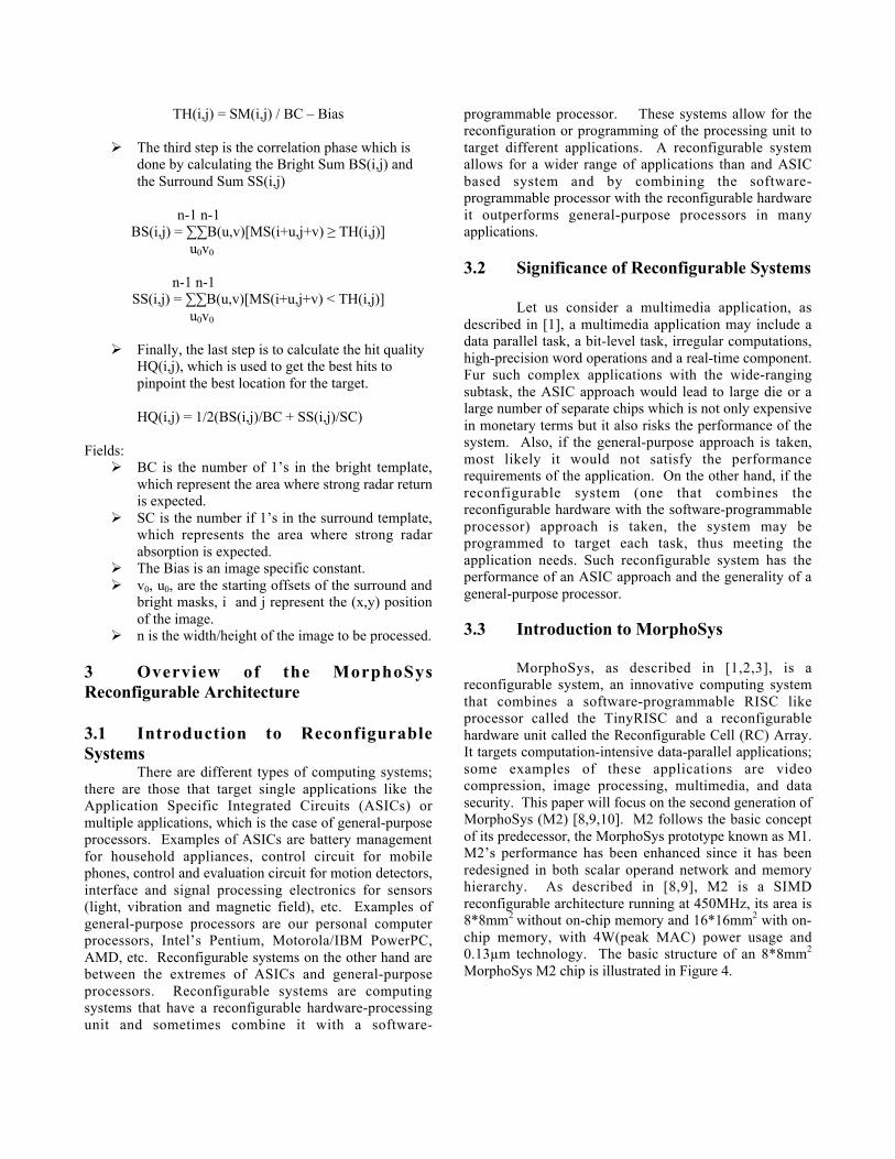
MorphoSys M2 chip is illustrated in Figure 4.
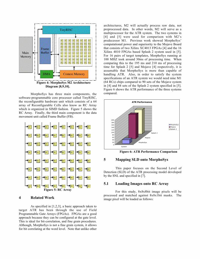
Figure 4: MorphoSys M2 ArchitectureDiagram [8,9,10].
MorphoSys has three main components, thesoftware-programmable core processor called TinyRISC,the reconfigurable hardware unit which consists of a 64array of Reconfigurable Cells also know as RC Arraywhich is organized in SIMD fashion. Figure 5 shows theRC Array. Finally, the third main component is the datamovement unit called Frame Buffer (FB).
Figure 5: RC Array
4 Related Work
As specified in [1,2,3], a basic approach taken totarget ATR has been through the use of FieldProgrammable Gate Arrays (FPGAs). FPGAs are a goodapproach because they can be configured at the gate level.This is ideal for bit-correlation, and fine grain procedures.Although, MorphoSys is not a fine grain system, it allowsfor bit correlating at the word level. Note that unlike other
architectures, M2 will actually process raw data, notpreprocessed data. In other words, M2 will serve as amultiprocessor for the ATR system. The two systems in[4] and [5] were used for comparison with M2’spredecessor M1. Previous work showed MorphoSys’computational power and superiority to the Mojave Boardthat consists of two Xilinx XC4013 FPGAs [4] and the 16Xilinx 4010 FPGAs based Splash 2 system used in [5].For 16 pairs of target templates, MorphoSys running at100 MHZ took around 30ms of processing time. Whencomparing this to the 195 ms and 210 ms of processingtime for Splash 2 [5] and Mojave [4] respectively, it isassumable that MorphoSys is more than capable ofhandling ATR. Also, in order to satisfy the systemspecifications of an ATR system we would need nine M1(64 RCs) chips compared to 90 sets of the Mojave systemin [4] and 84 sets of the Splash 2 system specified in [5].Figure 6 shows the ATR performance of the three systemscompared.
0
20
40
60
80
100
120
140
160
180
200
System
MorphoSys
Mojave
Splash 2
ATR Performance
MorphoSys
Mojave
Splash 2
Figure 6: ATR Performance Comparison
5 Mapping SLD onto MorphoSys
This paper focuses on the Second Level ofDetection (SLD) of the ATR processing model developedby the SNL and specified in [7].
5.1 Loading Images onto RC Array
For this study, 8x8x8bit image pixels will beprocessed and matched against 8x8x1bit masks. Theimage pixel will be loaded as follows:

Figure 7: 8x8x8bitImage loading into RC Array
ÿ For column i in RC Array, load row i of imageinto each RC of the current RC column as 8-8bitvalues. Where i is 0,1,…,7.
ÿ For each pixel k of the image store it into registerk of each RC. Where k is 0,1,…,7.
The next step is to load the 8x8x1bit bright andsurround templates (masks), and they will be loaded asfollows:
Figure 8: 8x8x1bit template loading into RC Array
ÿ For column i in RC Array, load row i in mask intoeach RC of the current load as an 8bit value.Where i is 0,1,…,7.
ÿ Store the 8bit value bright and surround mask inregisters 8 and 9 respectively.
5.2 Software Implementation
Before the algorithm mapping onto MorphoSys, asimulation program called SIM_ATR has been developed.SIM_ATR is a JAVA implementation that simulates theControl and RC Array processes, from data movement tothe algorithm implementation. SIM_ATR is implemented
in JAVA because of its features as an Object OrientedProgramming language.
The main feature of SIM_ATR is theRC_ARRAY class that has the ability to simulate theMorphoSys RC Array composed of 64 RCs, where eachRC runs its own processes. After each RC is done with itsprocess, SIM_ATR uses the RC_ARRAY class to performcolumn-wise operations as well as row-wise operationsjust as in the actual MorphoSys processor. Each column inRC_ARRAY runs a different process, thus, RC_ARRAYruns 8 different processes in parallel. SIM_ATR has abuilt in driver program that simulates a peak detector thatgets the offsets with the highest correlation results.
The purpose of SIM_ATR was to get familiarwith the SLD algorithm before doing the actualMorphoSys mapping and MuLate testing (MuLate is acycle accurate tool used to do the MorphoSys algorithmmapping). Note that SIM_ATR does not follow M2’sprogramming scheme. SIM_ATR simulation results willbe discussed in section 6.
5.3 MuLate Implementation
A full MuLate implementation of the ATR SLDalgorithm has been implemented. For the MuLateimplementation there are three main steps that must bedone in order to implement an algorithm in MorphoSysassembly. For more information on the programmingscheme followed by MorphoSys please refer to [10]. Theprocess is as follows:
ÿ The first step is to write RC Context. Context isthe terminology given to the programmingscheme used for MorphoSys’ Reconfigurablehardware called RC Array. Due to MorphoSys’SIMD fashion each context plane (8 instructionsgoing from 0 to 7 for each row/column) isprocessed in one cycle.
ÿ The second step is to write TinyRISC Assemblycode. TinyRISC is the software programmableunit of MorphoSys, it is used to control datamovement between Main Memory, Frame Bufferand RC Array as well as to execute row/columncontext.
ÿ Finally, all MuLate input data needs to beconverted into hexadecimal words (8 hex values,hex is a base 16 number). Context is convertedinto hex words through a Perl script tool calledmload, which was developed by the MorphoSysResearch Group. TinyRISC code is converted into
hex words through a C++ tool called trasm2002.Finally, all image data needs to be converted intohex as well, this is done through a binary/decimalJAVA converting tool called Hex_Converter.
In order to simulate the double summation required bythe SLD algorithm each RC will process the innersummation, and the outer summation will be processedperforming row-wise operations. Due to RC array’s SIMDnature, one instruction will be processed by all RCs in thesame column or row depending on how the contextspecifies it.
Figure 9: Row-wise operations for SLD algorithm
Figure 9 shows the row-wise operations needed tosimulate the outer summation of the SLD algorithm as wellas the row context for this operation. All three steps, theshape sum SM(i,j), the bright sum BS(i,j) and the surroundsum SS(i,j) require similar row-wise operations. The onlydifference is that the shape sum is a series of 8bitsummations and both surround and bright sum are 1bitsummations. Unlike other architectures, the actual SLDalgorithm was fully implemented by the RC Array, there isno preprocessed data. There are two assumptions beingmade, the first is that the FOA algorithm has given us animage containing a possible target and the second is thatthe 128x128x8bit pixel image will be divided into8x8x8bit pixel images for M2 to process them. Note thatwe can develop a system consisting of multiple M2 chipsthat will meet ATR’s specs.
6 Results and Conclusions
The SLD algorithm implementation on SIM_ATRwas able to detect both M47 tanks in a 128x128x8bit pixelreal image, taking an average time of 0.17ms for each8x8x8bit pixel image matching with the 8 pairs oftemplates mapped into the simulated RC_ARRAY.
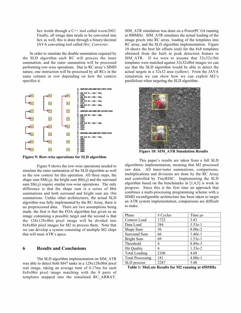
SIM_ATR simulation was done on a PowerPC G4 runningat 800MHz. SIM_ATR simulates the actual loading of theimage pixels into RC array, loading of the templates intoRC array, and the SLD algorithm implementation. Figure10 shows the best hit offsets (red) for the 8x8 templatesobtained from the built in peak detection feature inSIM_ATR. If we were to assume that 32x32x1bittemplates were matched against 32x32x8bit images we cansee that the SLD algorithm would be able to detect theactual targets in a 32x32 area (yellow). From the JAVAsimulation we can show how we can exploit M2’sparallelism when targeting the SLD algorithm.
Figure 10: SIM_ATR Simulation Results
This paper’s results are taken from a full SLDalgorithmic implementation, meaning that M2 processedraw data. All inner/outer summations, comparisons,multiplications and divisions are done by the RC Arrayand controlled by TinyRISC. Implementing the SLDalgorithm based on the benchmarks in [1,4,5] is work inprogress. Since this is the first time an approach thatcombines a multi-processing programming scheme with aSIMD reconfigurable architecture has been taken to targetan ATR system implementation, comparisons are difficultto make.
Phase # Cycles Time µsContext Load 1722 3.83Data Load 384 3.53e-1Shape Sum 36 8.00e-2Surround Sum 66 1.46e-1Bright Sum 69 1.53e-1Threshold 4 8.89e-3Hit Quality 6 1.33e-2Total Loading 2106 4.68Total Processing 181 4.00e-1SLD process 2287 5.08
Table 1: MuLate Results for M2 running at 450MHz

Table 1 shows the time in µs and number ofcycles for the SLD algorithm implementation on M2.Considering that usual chip images produced by the FOAalgorithm are 128x128x8bit pixels, if we use 8x8x1bittemplates, we would be looking at 121x121 correlationsfor 8 pairs of templates which means that 14,641 8x8chunks of the image would have to be processed.Considering that the entire processing of 8 8x8 templates is181 cycles (4.00e-1µs), we can say that for a 128x128image we would expect to take 5.89ms.
References
[1] H. Singh, Lee, Lu, Bagherzadeh, Kurdahi,“MorphoSys: An integrated Reconfigurable System forData-Parallel and Computation –Intensive Applications,”IEEE Transactions on Computers, vol. 49, No. 5, pp. 465-481, May 2000.[2] H. Sigh, M. Lee, G. Lu, F. Kurdahi, N.Bagherzadeh, T. Lang, R. Heaton, E. Filho. “An IntegratedRe-configurable Architecture.” NATO Symposium onConcepts and Integration, April 1998.[3] H. Singh, Lee, Lu, Bagherzadeh, Kurdahi,“Design and Implementation of the MorphoSysReconfigurable Computing Processor,” Journal of VLSISignal Processing Systems for Signal, Image, and VideoTechnology, vol. 24, No. 2-3, Kluwer AcademicPublishers, pp. 147-64, Mar 2000.[4] J. Villasenor, B. Schoner, K. Chia, C. Zapata, H.J. Kim, C. Jones, S. Lansing, and B. Mangione-Smith, “Configurable Computing Solutions for Automatic TargetRecognition,” Proceedings of IEEE Conference on FieldConfigurable Computing Machines, April 1996.[5] M. Rencher, B. Hutchings, " Automated TargetRecognition on SPLASH 2," Proc. of IEEE Symp. onFCCM, April 1997.[6] SANDIA National Laboratory - ATRwww.sandia.gov/atr[7] R. Sivilotti, Y. Cho, W. Su, and D. Cohen,“Scalable, Network-Connected, Reconfigurable HardwareAccelerators for an Automatic-Target RecognitionApplication,” Myricom Technical Report, May 1998.[8] Pan, Kamalizad, Koohi, Bagherzadeh, “Designand Analysis of a Programmable Single-Chip Architecturefor DVB-T Base-Band Reciever,” To Appear in DATE2003.[9] Kamalizad, Pan, Bagherzadeh, “A ReconfigurableComputation Platform and Case Study of Fast FFTImplementation,” To Appear in DATE 2003.[10] Kamalizad, “Several DBV-T Cores Mapping intoMorphoSys Architecture,” Masters Of Science Thesis2003.