Embed Size (px)
Citation preview
Jurnal Ilmiah Informatika dan Komputer Vol. 22 No. 2 Agustus 2017 111
A FAILURE MODE AND EFFECT ANALYSIS ON WATER RECIPROCATING PUMP FOR DRILLING INDUSTRY
Adam Satria
Fakultas Ilmu Komputer dan Teknologi Informasi, Universitas Gunadarma
Jl. Margonda Raya no. 100, Depok 16424, Jawa Barat [email protected]
Abstract
Pumps have been designed for a variety of purposes that operate to move liquid on high elevation and high pressure. One of them is a positive-displacement reciprocating duplex power pump. In drilling industry, it is used to circulate clean water to the supply tank, and to mix mud while simultaneously drilling. A Failure Mode and Effect Analysis (FMEA) was carried out on these pumps to analyze potential failures. In this study, the data of pump’s failures, occurrences, and detection methods were collected from PT Airtara Bekasi and interpreted on a criteria rank system to determine its Risk Priority Number (RPN). Discussions on recommended actions to decrease failure risks were conducted in brainstorming meetings. Of the whole RPN results, the highest score which was scored 224 was found in a Silicon-Controlled Rectifier. To reduce RPN score of this pump, several steps were applied, namely: installed bridge diode to reduce ripple wave on converted DC waveform, installed fuse current to prevent damage from shorting, improved the quality of drive current, and implemented proper installation circuit diagram. The FMEA was then repeated to determine the new score of revised RPN. It decreased significantly from 224 to 54 or it had about 76% reduction.
Keywords: Failure Mode and Effect Analysis, FMEA, Positive-Displacement Pump,
Power Pump, Reciprocating Pump
INTRODUCTIONS Pump is a mechanical device which
is driven by a power source that is used to move liquid (fluid) from one place to another, where the liquid flows only when there is a pressure difference. Pump can be defined as device to convert dynamic force to move the fluids into high pressured vessel. Besides being able to move the fluid, the pump also serves to increase the speed, pressure, and level of fluid [1, 2].
Pumps may be classified on the basis of the applications they serve, the materials from which they are construc-ted, the liquids they handle, and even their orientation in space [3]. Pumps
may be divided into two major cate-gories: Dynamic, and Displacement. A positive displacement pump causes a fluid to move by trapping a fixed amount on the suction side and forcing (dis-placing) that volume through the outlet. Positive displacement pumps have an expanding cavity, or area, on the suction side expands and a contracting cavity on the discharge side. Positive displacement pump produce the same flow at a given rotational speed regardless of discharge pressure [3, 4].
Positive displacement pumps divi-ded into two main groups, that is rotary pumps and reciprocating pumps. Reci-
112 Satria, A Failure Mode…
procating pumps include piston, plunger pumps, and diaphragm pumps. Recipro-cating pumps cause the fluid to move using one or more oscillating pistons, plungers, or membranes (diaphragms). Reciprocating pumps require a system of suction and discharge valves to ensure that fluid moves in one direction. Reci-procating positive displacement pump is one in which a plunger or piston displa-ces a given volume of fluid for each stroke. The basic principle of a recipro-cating pump is that a solid will displace an equal volume of liquid [3][4].
Failure Mode and Effects Analysis (FMEA) is one of the most popular methods for the systematic prevention of errors. The problem of early defect detec-tion has become so important to result in developing a method for identifying errors in the design phase of the product [5]. A failure mode and effect analysis (FMEA) is an engineering technique used to define, identity, and eliminate known and/or potential failure, problems , errors, and so on from the system, design, process, and/or service before they reach the customer [5]. A failure modes and effects analysis (FMEA) is a methodlo-gy in product development and opera-tions management for analysis of poten-tial failure modes within a system for classification by the severity and like-lihood of the failures [6].
A successful development of FM-EA is very important for product manu-facturers to deliver high quality products to their customers on time in turn the manufacturers will be able to compete in the global market [7]. FMEA helps the engineer to design reliable and safe product by mitigating the anticipated failure modes. The risk associated with each failure mode is evaluated using Risk Priority Number (RPN) which is calculated by multiplying severity (S), occurrence (O) and detection (D) ratings. Severity rating is assigned according to seriousness of an effect of a failure mode.
Occurrence rating is based on the failure probability during the product life. Similarly, detection rating is according to ability to identify a risk occurrence [8].
Rating scales usually range from 1 to 5 or from 1 to 10, with the higher number representing the higher serious-ness or risk. After the ratings have been assigned, the RPN for each issue is calcu-lated by multiplying Severity x Occurren-ce x Detection. In this study, the data of pump’s failures, occurrences, and detec-tion methods were collected from PT Airtara Bekasi and interpreted on a criteria rank system to determine its Risk Priority Number (RPN). Discussions on recommended actions to decrease failure risks were conducted in brainstorming meetings. RESEARCH METHOD
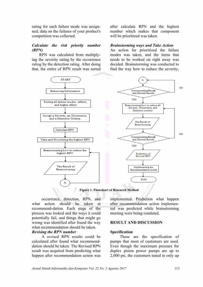
The first thing to run FMEA is to select the process to analyse. The impor-tance of the process in terms of the im-pact of potential failures is a parameter that has to be taken into account as selec-tion criteria. Research Method must be processed step by step as shown on Fi-gure 1.
Retrieving Information
An Information was gathered from personal communication with director, chief mechanic, and the entire staff of mechanic, then the process could be analysed and described in a flowchart.
Sorting Failure mode, Effect, and Higher Effect
The entire potential effects of each failure mode, the effect that caused, the higher effect for each component was listed. The potential effect of each failure was listed next to the failure.
Assign a Severity, an Occurrence, and a Detection Criteria
Severity, occurrence, and detection
Jurnal Ilmiah Informatika dan Komputer Vol. 22 No. 2 Agustus 2017 113
rating for each failure mode was assign-ned; data on the failures of your product's competition was collected.
Calculate the risk priority number (RPN)
RPN was calculated from multiply-ing the severity rating by the occurrence rating by the detection rating. After doing that, the entire of RPN result was sorted
after calculate RPN and the highest number which makes that component will be prioritized was taken.
Brainstorming ways and Take Action An action for prioritized the failure modes was taken, and the items that needs to be worked on right away was decided. Brainstorming was conducted to find the way how to reduce the severity,
Figure 1. Flowchart of Research Method
occurrence, detection, RPN, and what action should be taken at recommend-dation. Each stage of the process was looked and the ways it could potentially fail, and things that might go wrong was identified after found the way what recommendation should be taken. Revising the RPN number
A revised RPN results could be calculated after found what recommend-dation should be taken. The Revised RPN result was acquired from predicting what happen after recommendation action was
implemented. Prediction what happen after recommendation action implemen-ted was predicted while brainstorming meeting were being conduted. RESULT AND DISCUSSION Specification
These are the specification of pumps that most of customers are used. Even though the maximum pressure for duplex piston power pumps are up to 2,000 psi, the customers tuned in only up
114 Satria, A Failure Mode…
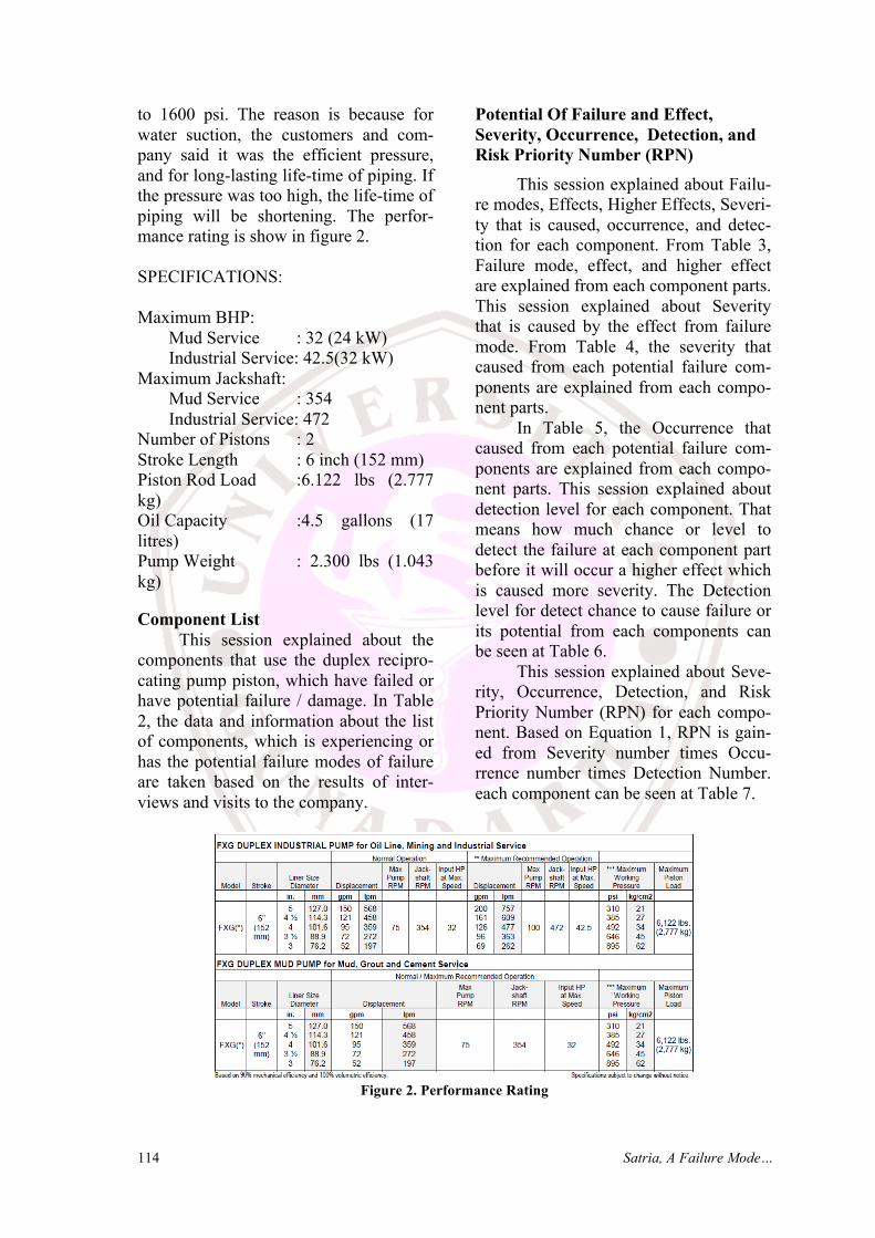
to 1600 psi. The reason is because for water suction, the customers and com-pany said it was the efficient pressure, and for long-lasting life-time of piping. If the pressure was too high, the life-time of piping will be shortening. The perfor-mance rating is show in figure 2. SPECIFICATIONS: Maximum BHP:
Mud Service : 32 (24 kW) Industrial Service: 42.5(32 kW)
Maximum Jackshaft: Mud Service : 354 Industrial Service: 472
Number of Pistons : 2 Stroke Length : 6 inch (152 mm) Piston Rod Load :6.122 lbs (2.777 kg) Oil Capacity :4.5 gallons (17 litres) Pump Weight : 2.300 lbs (1.043 kg)
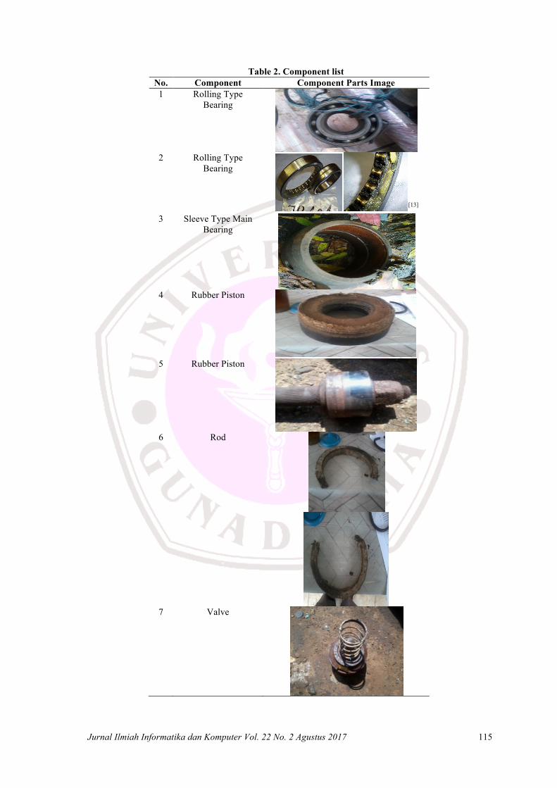
Component List This session explained about the
components that use the duplex recipro-cating pump piston, which have failed or have potential failure / damage. In Table 2, the data and information about the list of components, which is experiencing or has the potential failure modes of failure are taken based on the results of inter-views and visits to the company.
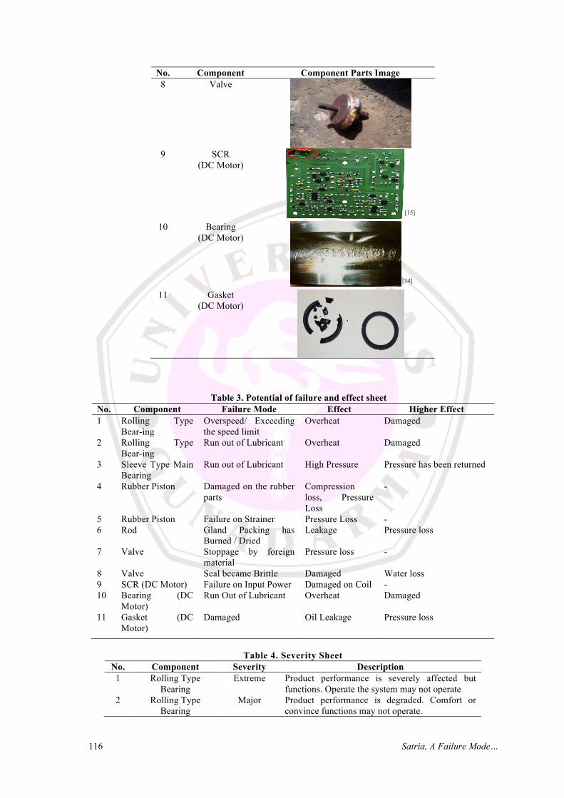
Potential Of Failure and Effect, Severity, Occurrence, Detection, and Risk Priority Number (RPN)
This session explained about Failu-re modes, Effects, Higher Effects, Severi-ty that is caused, occurrence, and detec-tion for each component. From Table 3, Failure mode, effect, and higher effect are explained from each component parts. This session explained about Severity that is caused by the effect from failure mode. From Table 4, the severity that caused from each potential failure com-ponents are explained from each compo-nent parts.
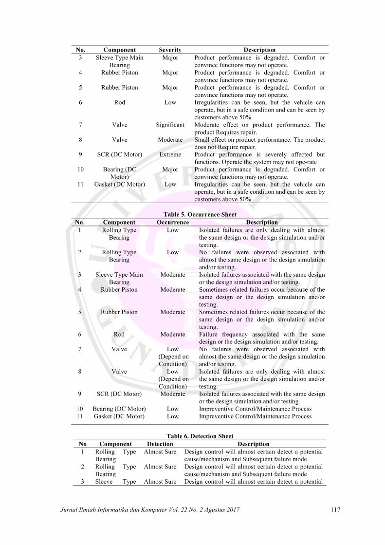
In Table 5, the Occurrence that caused from each potential failure com-ponents are explained from each compo-nent parts. This session explained about detection level for each component. That means how much chance or level to detect the failure at each component part before it will occur a higher effect which is caused more severity. The Detection level for detect chance to cause failure or its potential from each components can be seen at Table 6.
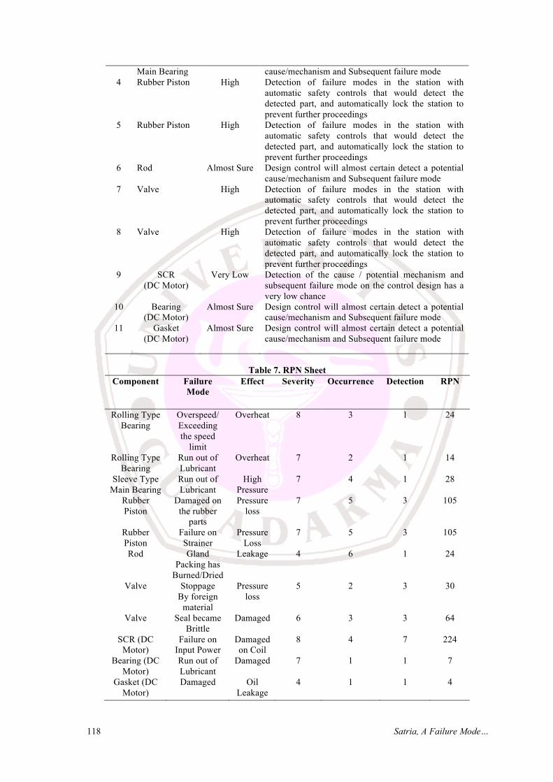
This session explained about Seve-rity, Occurrence, Detection, and Risk Priority Number (RPN) for each compo-nent. Based on Equation 1, RPN is gain-ed from Severity number times Occu-rrence number times Detection Number. each component can be seen at Table 7.
Figure 2. Performance Rating
Jurnal Ilmiah Informatika dan Komputer Vol. 22 No. 2 Agustus 2017 115
Table 2. Component list No. Component Component Parts Image 1 Rolling Type
Bearing
2 Rolling Type Bearing
[13] 3 Sleeve Type Main
Bearing
4 Rubber Piston
5 Rubber Piston
6 Rod
7 Valve
116 Satria, A Failure Mode…
No. Component Component Parts Image 8 Valve
9 SCR (DC Motor)
[15] 10 Bearing
(DC Motor)
[14] 11 Gasket
(DC Motor)
Table 3. Potential of failure and effect sheet No. Component Failure Mode Effect Higher Effect 1 Rolling Type
Bear-ing Overspeed/ Exceeding the speed limit
Overheat Damaged
2 Rolling Type Bear-ing
Run out of Lubricant Overheat Damaged
3 Sleeve Type Main Bearing
Run out of Lubricant High Pressure Pressure has been returned
4 Rubber Piston Damaged on the rubber parts
Compression loss, Pressure Loss
-
5 Rubber Piston Failure on Strainer Pressure Loss - 6 Rod Gland Packing has
Burned / Dried Leakage Pressure loss
7 Valve Stoppage by foreign material
Pressure loss -
8 Valve Seal became Brittle Damaged Water loss 9 SCR (DC Motor) Failure on Input Power Damaged on Coil - 10 Bearing (DC
Motor) Run Out of Lubricant Overheat Damaged
11 Gasket (DC Motor)
Damaged Oil Leakage Pressure loss
Table 4. Severity Sheet
No. Component Severity Description 1 Rolling Type
Bearing Extreme Product performance is severely affected but
functions. Operate the system may not operate 2 Rolling Type
Bearing Major Product performance is degraded. Comfort or
convince functions may not operate.
Jurnal Ilmiah Informatika dan Komputer Vol. 22 No. 2 Agustus 2017 117
No. Component Severity Description 3 Sleeve Type Main
Bearing Major Product performance is degraded. Comfort or
convince functions may not operate. 4 Rubber Piston Major Product performance is degraded. Comfort or
convince functions may not operate. 5 Rubber Piston Major Product performance is degraded. Comfort or
convince functions may not operate. 6 Rod Low Irregularities can be seen, but the vehicle can
operate, but in a safe condition and can be seen by customers above 50%.
7 Valve Significant Moderate effect on product performance. The product Requires repair.
8 Valve Moderate Small effect on product performance. The product does not Require repair.
9 SCR (DC Motor) Extreme Product performance is severely affected but functions. Operate the system may not ope-rate
10 Bearing (DC Motor)
Major Product performance is degraded. Comfort or convince functions may not operate.
11 Gasket (DC Motor) Low Irregularities can be seen, but the vehicle can operate, but in a safe condition and can be seen by customers above 50%.
Table 5. Occurrence Sheet
No. Component Occurrence Description 1 Rolling Type
Bearing Low Isolated failures are only dealing with almost
the same design or the design simulation and/or testing.
2 Rolling Type Bearing
Low No failures were observed associated with almost the same design or the design simulation and/or testing.
3 Sleeve Type Main Bearing
Moderate Isolated failures associated with the same design or the design simulation and/or testing.
4 Rubber Piston Moderate Sometimes related failures occur because of the same design or the design simulation and/or testing.
5 Rubber Piston Moderate Sometimes related failures occur because of the same design or the design simulation and/or testing.
6 Rod Moderate Failure frequency associated with the same design or the design simulation and/or testing.
7 Valve Low (Depend on Condition)
No failures were observed associated with almost the same design or the design simulation and/or testing.
8 Valve Low (Depend on Condition)
Isolated failures are only dealing with almost the same design or the design simulation and/or testing.
9 SCR (DC Motor) Moderate Isolated failures associated with the same design or the design simulation and/or testing.
10 Bearing (DC Motor) Low Impreventive Control/Maintenance Process 11 Gasket (DC Motor) Low Impreventive Control/Maintenance Process
Table 6. Detection Sheet
No Component Detection Description 1 Rolling Type
Bearing Almost Sure Design control will almost certain detect a potential
cause/mechanism and Subsequent failure mode 2 Rolling Type
Bearing Almost Sure Design control will almost certain detect a potential
cause/mechanism and Subsequent failure mode 3 Sleeve Type Almost Sure Design control will almost certain detect a potential
118 Satria, A Failure Mode…
Main Bearing cause/mechanism and Subsequent failure mode 4 Rubber Piston High Detection of failure modes in the station with
automatic safety controls that would detect the detected part, and automatically lock the station to prevent further proceedings
5 Rubber Piston High Detection of failure modes in the station with automatic safety controls that would detect the detected part, and automatically lock the station to prevent further proceedings
6 Rod Almost Sure Design control will almost certain detect a potential cause/mechanism and Subsequent failure mode
7 Valve High Detection of failure modes in the station with automatic safety controls that would detect the detected part, and automatically lock the station to prevent further proceedings
8 Valve High Detection of failure modes in the station with automatic safety controls that would detect the detected part, and automatically lock the station to prevent further proceedings
9 SCR (DC Motor)
Very Low Detection of the cause / potential mechanism and subsequent failure mode on the control design has a very low chance
10 Bearing (DC Motor)
Almost Sure Design control will almost certain detect a potential cause/mechanism and Subsequent failure mode
11 Gasket (DC Motor)
Almost Sure Design control will almost certain detect a potential cause/mechanism and Subsequent failure mode
Table 7. RPN Sheet
Component Failure Mode
Effect Severity Occurrence Detection RPN
Rolling Type Bearing
Overspeed/ Exceeding the speed
limit
Overheat 8 3 1 24
Rolling Type Bearing
Run out of Lubricant
Overheat 7 2 1 14
Sleeve Type Main Bearing
Run out of Lubricant
High Pressure
7 4 1 28
Rubber Piston
Damaged on the rubber
parts
Pressure loss
7 5 3 105
Rubber Piston
Failure on Strainer
Pressure Loss
7 5 3 105
Rod Gland Packing has
Burned/Dried
Leakage 4 6 1 24
Valve Stoppage By foreign
material
Pressure loss
5 2 3 30
Valve Seal became Brittle
Damaged 6 3 3 64
SCR (DC Motor)
Failure on Input Power
Damaged on Coil
8 4 7 224
Bearing (DC Motor)
Run out of Lubricant
Damaged 7 1 1 7
Gasket (DC Motor)
Damaged Oil Leakage
4 1 1 4
Jurnal Ilmiah Informatika dan Komputer Vol. 22 No. 2 Agustus 2017 119
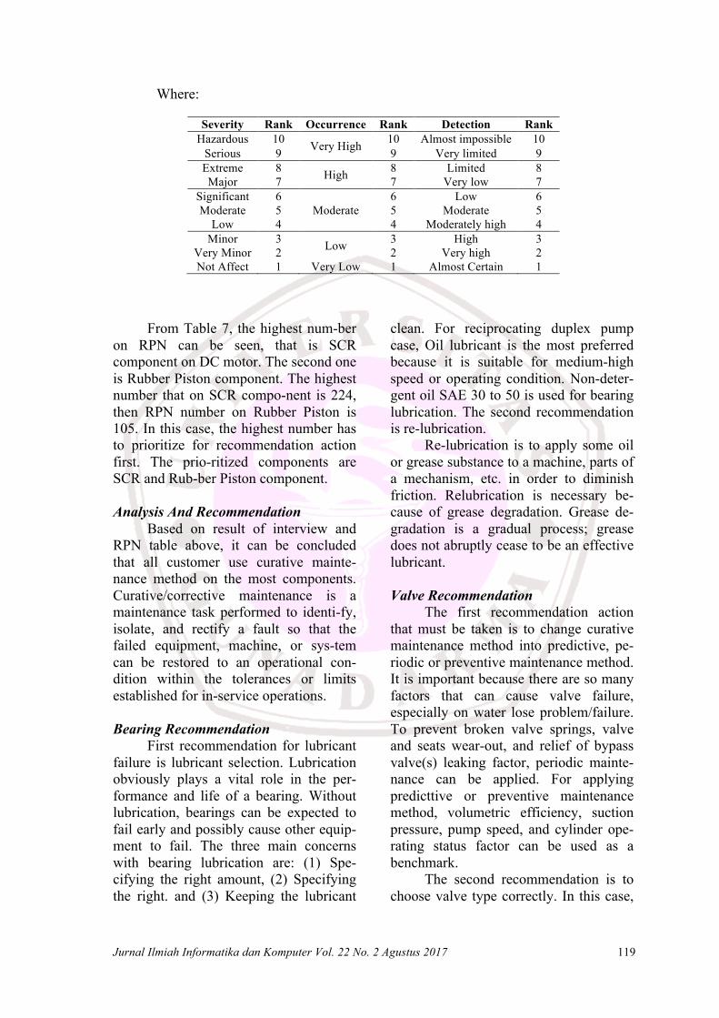
Where:
Severity Rank Occurrence Rank Detection Rank Hazardous 10 Very High 10 Almost impossible 10
Serious 9 9 Very limited 9 Extreme 8 High 8 Limited 8 Major 7 7 Very low 7
Significant 6 Moderate
6 Low 6 Moderate 5 5 Moderate 5
Low 4 4 Moderately high 4 Minor 3 Low 3 High 3
Very Minor 2 2 Very high 2 Not Affect 1 Very Low 1 Almost Certain 1
From Table 7, the highest num-ber on RPN can be seen, that is SCR component on DC motor. The second one is Rubber Piston component. The highest number that on SCR compo-nent is 224, then RPN number on Rubber Piston is 105. In this case, the highest number has to prioritize for recommendation action first. The prio-ritized components are SCR and Rub-ber Piston component. Analysis And Recommendation
Based on result of interview and RPN table above, it can be concluded that all customer use curative mainte-nance method on the most components. Curative/corrective maintenance is a maintenance task performed to identi-fy, isolate, and rectify a fault so that the failed equipment, machine, or sys-tem can be restored to an operational con-dition within the tolerances or limits established for in-service operations. Bearing Recommendation
First recommendation for lubricant failure is lubricant selection. Lubrication obviously plays a vital role in the per-formance and life of a bearing. Without lubrication, bearings can be expected to fail early and possibly cause other equip-ment to fail. The three main concerns with bearing lubrication are: (1) Spe-cifying the right amount, (2) Specifying the right. and (3) Keeping the lubricant
clean. For reciprocating duplex pump case, Oil lubricant is the most preferred because it is suitable for medium-high speed or operating condition. Non-deter-gent oil SAE 30 to 50 is used for bearing lubrication. The second recommendation is re-lubrication.
Re-lubrication is to apply some oil or grease substance to a machine, parts of a mechanism, etc. in order to diminish friction. Relubrication is necessary be-cause of grease degradation. Grease de-gradation is a gradual process; grease does not abruptly cease to be an effective lubricant.
Valve Recommendation
The first recommendation action that must be taken is to change curative maintenance method into predictive, pe-riodic or preventive maintenance method. It is important because there are so many factors that can cause valve failure, especially on water lose problem/failure. To prevent broken valve springs, valve and seats wear-out, and relief of bypass valve(s) leaking factor, periodic mainte-nance can be applied. For applying predicttive or preventive maintenance method, volumetric efficiency, suction pressure, pump speed, and cylinder ope-rating status factor can be used as a benchmark.
The second recommendation is to choose valve type correctly. In this case,
120 Satria, A Failure Mode…
plate and wing type are the best option. Depend on customers pump, for plate type, it is the best when the pressure pump is 5,000 PSI, and for wing type is 10,000 PSI. If not choose valve type correctly, it will cause excessive suction lift, low volumetric efficiency, and not enough suction pressure that cause valves and seats wear-out, and its effect is water loss failure.
Rubber Piston Recommendation Because of the close tolerances
between the pistons and the cylinder walls, reciprocating pumps cannot tole-rate contaminated liquid in their suction-supply system. If the customers do not install strainer and foot-valve (non-return type) on the pump, the first recommend-dation is install it. If the customers only install strainer, adding the foot-valve is recommended. The foot-valve allows water to flow only in the upward direc-tion in the suction pipe. It helps for the strainer to filter foreign material on the best condition.
The second recommendation is to changes curative/corrective maintenance method become periodical and preven-tive maintenance method. For cleaning filter, strainer, and valve check, it should be done in the daily checks. Then for water leaks check, it should be done in the daily checks too. For seal, strainer, and valve change, each system’s main-tenance cycle will differ. If system performance decreases, check immedia-tely. If no wear at 1,500 hours, check again at 2,000 hours and each 500 hours until wear is observed. Valve typically requires changing every other seal change. Checking and changing the time can vary according to the evaluation, and reference from each manufacturer. It is important to follow the manufacturer’s recommendations for valve, seal, and strainer maintenance and replacement.
The third recommendation is to choose strainer correctly. The strainer
should be chosen depends on customer desire, environmental, liquid type, pressure, mesh/filtration size range, filtration area, piping shape and size, and how long the customer want to use strainer (temporary or permanent). Rod (Gland Packing) Recommendation
The first recommendation is lubri-cation of packing selection. There are two type of lubricant; it is grease and oil lubricant. Under conditions of heavy use and at the recommendation of some manufacturers, packing is lubricated and cooled with grease or oil. Various types of grease cups and auto motor oiling arrangements are used. Regardless of the type of installation, care should be taken to obtain the proper type of grease or oil. The second recommendation is the customer have to learn and know how to proper packing installation. One cause of packing failure is improper packing installation.
This recommendation is to prevent it. To ensure proper installation, first measure the packing for consistent width. Don't rely on what's printed on the spool or box. Next, inspect the old rings as discussed above, and look at the stuffing box and sleeve. Don't ignore gouges or burrs, as they will gradually destroy any packing. Also, many packing rings will shrink over time, and misdirected cooling water will seep outside the rings, causing them to become hard and fail. Replacing damaged equipment now will eliminate more serious problems later on.
The third recommendation is packing selection. By selecting the pro-per packing, making sure there are no equipment problems, and installing the packing correctly, the customer will be able to rely on this packing until the next scheduled packing replacement. Normal periodic inspections are all that should be required along the way. Packing is selected for the pump operating pressure,
Jurnal Ilmiah Informatika dan Komputer Vol. 22 No. 2 Agustus 2017 121
shaft speed, pumped fluid temperature and type of fluid being pumped. SCR (DC Motor) Recommendation
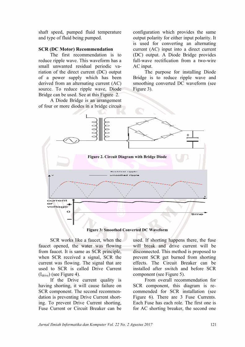
The first recommendation is to reduce ripple wave. This waveform has a small unwanted residual periodic va-riation of the direct current (DC) output of a power supply which has been derived from an alternating current (AC) source. To reduce ripple wave, Diode Bridge can be used. See at this Figure 2.
A Diode Bridge is an arrangement of four or more diodes in a bridge circuit
configuration which provides the same output polarity for either input polarity. It is used for converting an alternating current (AC) input into a direct current (DC) output. A Diode Bridge provides full-wave rectification from a two-wire AC input.
The purpose for installing Diode Bridge is to reduce ripple wave and smoothing converted DC waveform (see Figure 3).
Figure 2. Circuit Diagram with Bridge Diode
Figure 3: Smoothed Converted DC Waveform
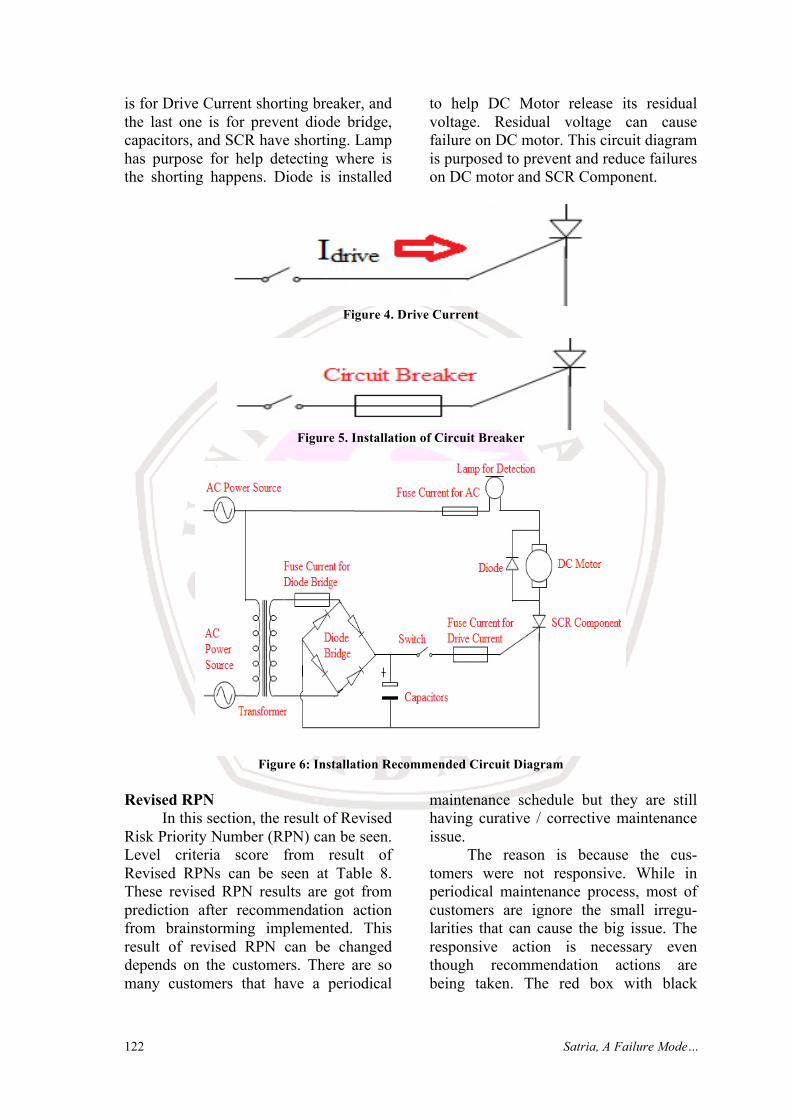
SCR works like a faucet, when the faucet opened, the water was flowing from faucet. It is same as SCR principle, when SCR received a signal, SCR the current was flowing. The signal that are used to SCR is called Drive Current (Idrive) (see Figure 4).
If the Drive current quality is having shorting, it will cause failure on SCR component. The second recommen-dation is preventing Drive Current short-ing. To prevent Drive Current shorting, Fuse Current or Circuit Breaker can be
used. If shorting happens there, the fuse will break and drive current will be disconnected. This method is proposed to prevent SCR get burned from shorting effects. The Circuit Breaker can be installed after switch and before SCR component (see Figure 5).
From overall recommendation for SCR component, this diagram is re-commended for SCR installation (see Figure 6). There are 3 Fuse Currents. Each Fuse has each role. The first one is for AC shorting breaker, the second one
122 Satria, A Failure Mode…
is for Drive Current shorting breaker, and the last one is for prevent diode bridge, capacitors, and SCR have shorting. Lamp has purpose for help detecting where is the shorting happens. Diode is installed
to help DC Motor release its residual voltage. Residual voltage can cause failure on DC motor. This circuit diagram is purposed to prevent and reduce failures on DC motor and SCR Component.
Figure 4. Drive Current
Figure 5. Installation of Circuit Breaker
Figure 6: Installation Recommended Circuit Diagram
Revised RPN
In this section, the result of Revised Risk Priority Number (RPN) can be seen. Level criteria score from result of Revised RPNs can be seen at Table 8. These revised RPN results are got from prediction after recommendation action from brainstorming implemented. This result of revised RPN can be changed depends on the customers. There are so many customers that have a periodical
maintenance schedule but they are still having curative / corrective maintenance issue.
The reason is because the cus-tomers were not responsive. While in periodical maintenance process, most of customers are ignore the small irregu-larities that can cause the big issue. The responsive action is necessary even though recommendation actions are being taken. The red box with black
Jurnal Ilmiah Informatika dan Komputer Vol. 22 No. 2 Agustus 2017 123
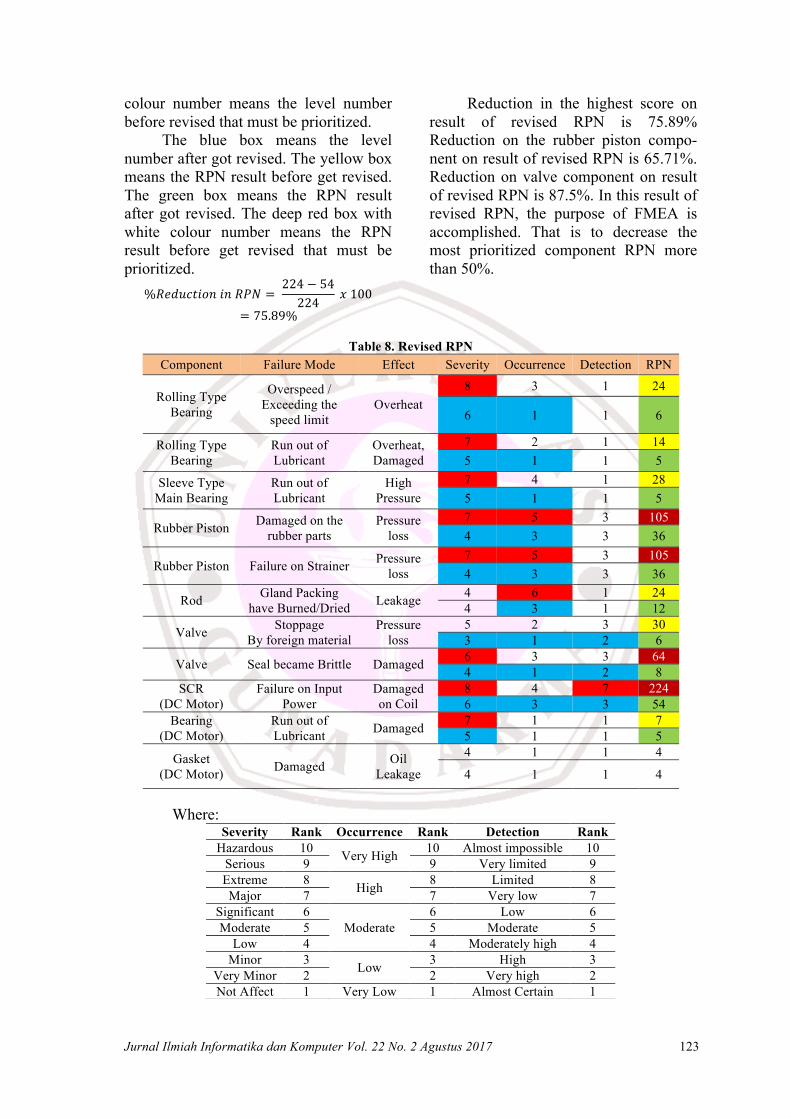
colour number means the level number before revised that must be prioritized.
The blue box means the level number after got revised. The yellow box means the RPN result before get revised. The green box means the RPN result after got revised. The deep red box with white colour number means the RPN result before get revised that must be prioritized.
%𝑅𝑒𝑑𝑢𝑐𝑡𝑖𝑜𝑛𝑖𝑛𝑅𝑃𝑁 = 224 − 54224
𝑥100= 75.89%
Reduction in the highest score on result of revised RPN is 75.89% Reduction on the rubber piston compo-nent on result of revised RPN is 65.71%. Reduction on valve component on result of revised RPN is 87.5%. In this result of revised RPN, the purpose of FMEA is accomplished. That is to decrease the most prioritized component RPN more than 50%.
Table 8. Revised RPN
Component Failure Mode Effect Severity Occurrence Detection RPN
Rolling Type Bearing
Overspeed / Exceeding the
speed limit Overheat
8 3 1 24
6 1 1 6
Rolling Type Bearing
Run out of Lubricant
Overheat, Damaged
7 2 1 14 5 1 1 5
Sleeve Type Main Bearing
Run out of Lubricant
High Pressure
7 4 1 28 5 1 1 5
Rubber Piston Damaged on the rubber parts
Pressure loss
7 5 3 105 4 3 3 36
Rubber Piston Failure on Strainer Pressure loss
7 5 3 105 4 3 3 36
Rod Gland Packing have Burned/Dried Leakage 4 6 1 24
4 3 1 12
Valve Stoppage By foreign material
Pressure loss
5 2 3 30 3 1 2 6
Valve Seal became Brittle Damaged 6 3 3 64 4 1 2 8
SCR (DC Motor)
Failure on Input Power
Damaged on Coil
8 4 7 224 6 3 3 54
Bearing (DC Motor)
Run out of Lubricant Damaged 7 1 1 7
5 1 1 5
Gasket (DC Motor) Damaged Oil
Leakage
4 1 1 4
4 1 1 4
Where: Severity Rank Occurrence Rank Detection Rank
Hazardous 10 Very High 10 Almost impossible 10 Serious 9 9 Very limited 9 Extreme 8 High 8 Limited 8 Major 7 7 Very low 7
Significant 6 Moderate
6 Low 6 Moderate 5 5 Moderate 5
Low 4 4 Moderately high 4 Minor 3 Low 3 High 3
Very Minor 2 2 Very high 2 Not Affect 1 Very Low 1 Almost Certain 1
124 Satria, A Failure Mode…
Conclusion
The highest number in severity criteria is on Rolling type Bearing and SCR component. The highest number in occurrence criteria is on rubber piston and rod component. The highest number in detection criteria is on SCR com-ponent. The highest number in RPN is on Silicon Controller-Rectifier (SCR) on DC motor component, and Rubber piston on Pump Component. Because of this, the highest number in RPN becomes the most prioritized component for re-commendation action that must be taken.
For Bearing Components, its recommendations are lubricant selection and Re-lubrication. For reciprocating duplex pump case, Oil lubricant is the most preferred because it is suitable for medium-high speed or operating con-dition. Non-detergent oil SAE 30 to 50 is used for bearing lubrication.
For Valve Components, its re-commendations are to change curative maintenance method into predictive, periodic or preventive maintenance method and to choose valve type correct-ly. Depend on customers pump, for plate type, it is the best when the pressure pump is 5,000 PSI, and for wing type is 10,000 PSI. For Rubber Piston Com-ponents, its recommendations are install-ing strainer (if the pump does not have it) and foot-valve (non-return type) on the pump, changes curative/corrective main-tenance method become periodical and preventive maintenance method, and choose strainer correctly.
For Rod (Gland Packing parts) Components, its recommendations are lubrication of packing selection, learn and know how to proper packing ins-tallation, and packing selection. For Silicon-Controlled Rectifier Component, its recommendation is to reduce ripple wave at converted DC waveform into pure DC waveform, prevent drive current shorting, installing fuse current / Circuit
breaker, and release residual voltage on DC motor.
The most prioritized component that has the highest number in RPN, has become reduced from 224 score to become 54 for SCR component, and from 105 to become 36 for Rubber Piston component. The responsive action is ne-cessary even though recommendation actions are being taken. Reduction in the highest score on prediction result of revised RPN is 75.89%. REFERENCES [1] Arif Indra Baskoro, Sediono,
Windu. 2013. Analisa Performa Efisiensi pada Sea Water Booster Pump Unit 10 PLTU Jawa Tengah Rembang. Undergraduate thesis. Universitas Diponogoro.
[2] Putra, Rudiansyah. 2012. Kemam-puan Kerja Operasi Pompa Torak (Reciprocating) Terhadap Kapasi-tas Yang Dihasilkan Di Pabrik Mini PTKI Medan. Skripsi. Univer-sitas Sumatera Utara.
[3] Igor J. Karassik, Joseph P. Messina, Paul Cooper, Charles C. Heald. 2001. Pump Handbook . Third Edition. New York: McGRAW-HILL.
[4] Neil McManus, Thomas. 2013. Management of hadardous Energi: Deactivation, De-Energization, Iso-lation, and Lockout. Boca Raton : CRC Press.
[5] Roszak, M., Spilka, M. And Kania, A. 2015. ” Environmental Failure Mode And Effects Analysis (FM-EA) A New Approach To Metho-dology”. METALURGIJA. Vol. 54, No.2, pp. 449-451.
[6] Ambekar , Swapnil B., Edlabadkar, Ajinkya and Shrouty, Vivek. 2013. “A Review: Implementation of Failure Mode and Effect Analysis”. International Journal of Engi-
Jurnal Ilmiah Informatika dan Komputer Vol. 22 No. 2 Agustus 2017 125
neering and Innovative Technology (IJEIT). Vol.2, No.8, pp. 37 – 41.
[7] Vaibhav. S. Kamble and T. Z. Quazi. 2014. “FMEA of shell moulding process and prioritizing by using AHP”. International Journal of Research in Aero-nautical and Mechanical Engi-neering. Vol. 2, No.6, pp. 161-176.
[8] Mehrzad Ebrahemzadih, G. H. Halvani, Behzad Shahmoradi and Omid Giahi. 2014. “Assessment and Risk Management of Potential Hazards by Failure Modes and Effect Analysis (FMEA) Method in Yazd Steel Complex”. Journal of Safety Science and Technology. Vol. 4, pp. 127-135.


![Heart Failure Master [Compatibility Mode]](https://img.pdfslide.us/doc/110x75/577ccf1b1a28ab9e788ee487/heart-failure-master-compatibility-mode.jpg)