Embed Size (px)
Citation preview

Dr Elie Allouis Mission and Robotics Systems Engineer [email protected]
Rick Blake Roger Ward
Peter Truss Brian Maddison
Sev Gunes-Lasnet
Tony Jorden Elie Allouis
Matthew Stuttard
A Facility for the Verification and Validation of Robotics and Autonomy for Planetary
Applications
ASTRA 2013 - 16th May ESTEC
Scope
1 - Introduction 2 - The Verification and Validation (V&V) Process 3 – System level V&V needs 4 – Review of Capabilities and Facilities 5 – Gap Analysis and Proposed ESA Facility Concept 6 – Implementation and support beyond the space sector 7 - Conclusion
2
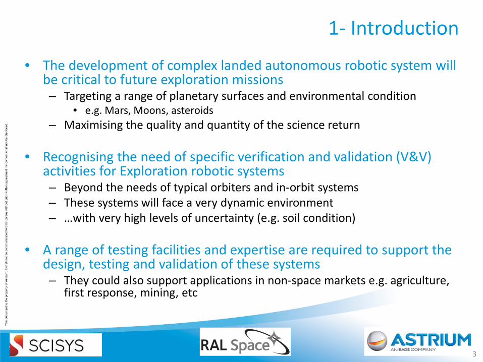
1- Introduction
• The development of complex landed autonomous robotic system will be critical to future exploration missions – Targeting a range of planetary surfaces and environmental condition
• e.g. Mars, Moons, asteroids – Maximising the quality and quantity of the science return
• Recognising the need of specific verification and validation (V&V) activities for Exploration robotic systems – Beyond the needs of typical orbiters and in-orbit systems – These systems will face a very dynamic environment – …with very high levels of uncertainty (e.g. soil condition)
• A range of testing facilities and expertise are required to support the
design, testing and validation of these systems – They could also support applications in non-space markets e.g. agriculture,
first response, mining, etc
3
1- Introduction – The HRAF Study
• This paper presents the main outcome of the Harwell Robotic and Autonomy Facility (HRAF) study
– This study was conducted by a consortium composed of RAL Space, Astrium and SCISYS on behalf of ESA.
• This initiative is at the heart of a joint effort between ESA, national agencies, research institutes and industry to support the testing and validation of robotics and autonomy for space exploration.
• The primary outcome of this study is a proposal for a Facility to be established at ESA Harwell and supported by the UK Space Agency
4
1- Introduction – Study Methodology
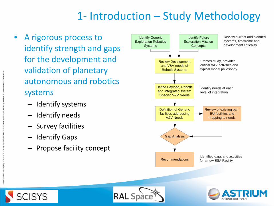
• A rigorous process to identify strength and gaps for the development and validation of planetary autonomous and robotics systems – Identify systems – Identify needs – Survey facilities – Identify Gaps – Propose facility concept
Identify Generic Exploration Robotics
Systems
Review Development and V&V needs of Robotic Systems
Frames study, provides critical V&V activities and typical model philosophy
Define Payload, Robotic and Integrated system Specific V&V Needs
Definition of Generic facilities addressing
V&V Needs
Review of existing pan-EU facilities and
mapping to needs
Recommendations
Gap Analysis
Identify Future Exploration Mission
Concepts
Identify needs at each level of integration
Review current and planned systems, timeframe and development criticality
Identified gaps and activities for a new ESA Facility
2- The Verification and Validation Process
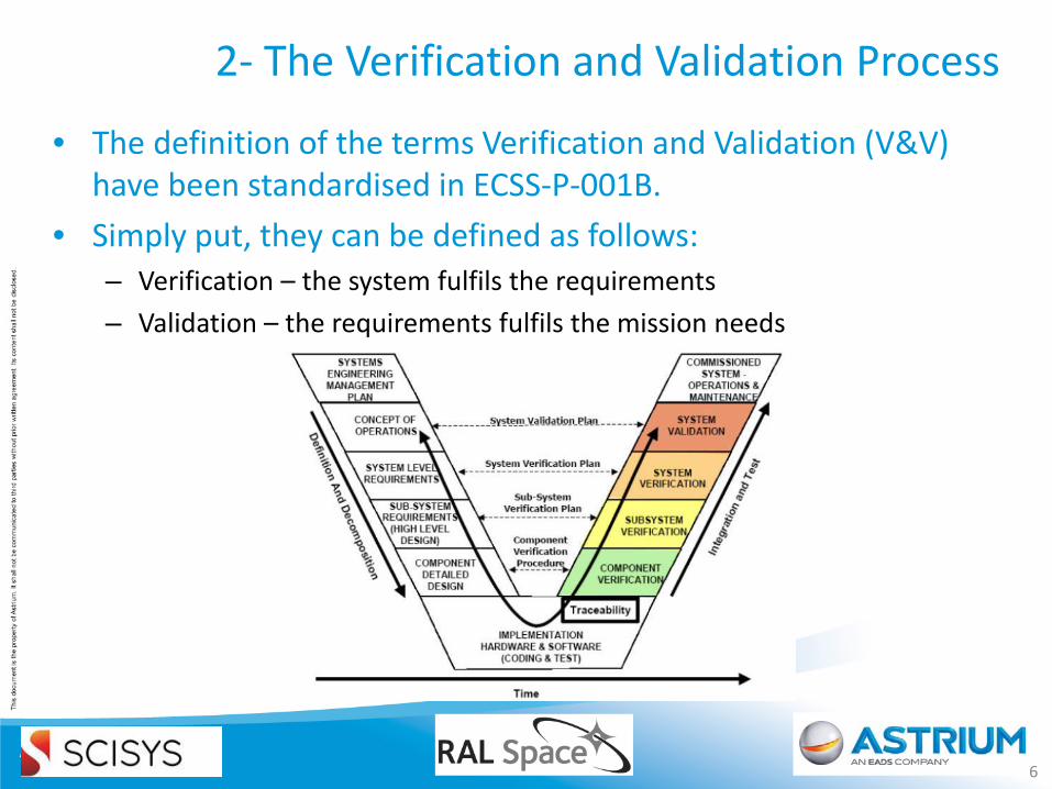
• The definition of the terms Verification and Validation (V&V) have been standardised in ECSS-P-001B.
• Simply put, they can be defined as follows: – Verification – the system fulfils the requirements – Validation – the requirements fulfils the mission needs
6
2- The Verification and Validation Process
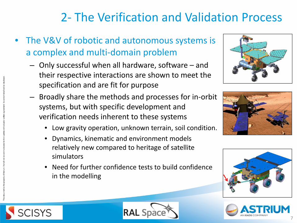
• The V&V of robotic and autonomous systems is a complex and multi-domain problem – Only successful when all hardware, software – and
their respective interactions are shown to meet the specification and are fit for purpose
– Broadly share the methods and processes for in-orbit systems, but with specific development and verification needs inherent to these systems
• Low gravity operation, unknown terrain, soil condition. • Dynamics, kinematic and environment models
relatively new compared to heritage of satellite simulators
• Need for further confidence tests to build confidence in the modelling
7
2- The Verification and Validation Process
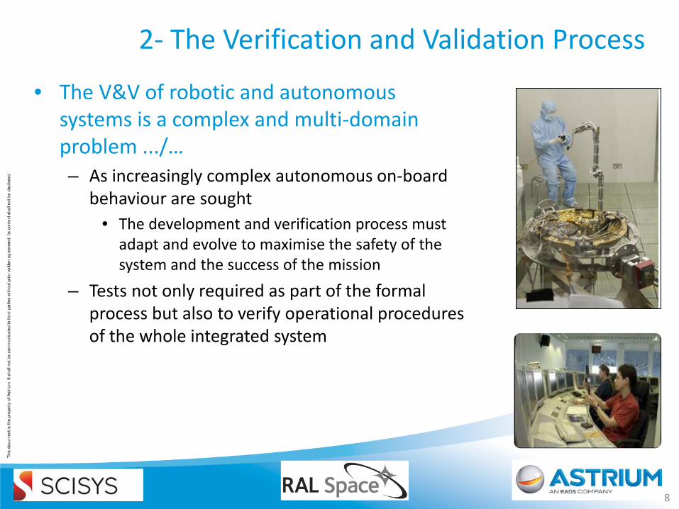
• The V&V of robotic and autonomous systems is a complex and multi-domain problem .../… – As increasingly complex autonomous on-board
behaviour are sought • The development and verification process must
adapt and evolve to maximise the safety of the system and the success of the mission
– Tests not only required as part of the formal process but also to verify operational procedures of the whole integrated system
8
2- The Verification and Validation Process
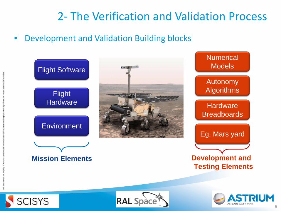
• Development and Validation Building blocks
9
Flight SoftwareFlight Software
Numerical Models
Numerical Models
Hardware Breadboards
Hardware Breadboards
Eg. Mars yardEg. Mars yard
Flight Hardware
Flight Hardware
EnvironmentEnvironment
Mission Elements Development and Testing Elements
Autonomy AlgorithmsAutonomy Algorithms
3 - System Level V&V needs
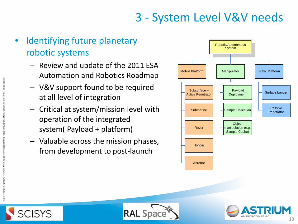
• Identifying future planetary robotic systems – Review and update of the 2011 ESA
Automation and Robotics Roadmap – V&V support found to be required
at all level of integration – Critical at system/mission level with
operation of the integrated system( Payload + platform)
– Valuable across the mission phases, from development to post-launch
10
Robotic/Autonomous System
Mobile Platform Manipulator Static Platform
Rover
Hopper
Aerobot
Subsurface – Active Penetrator
Submarine
Payload Deployment
Sample Collection
Object manipulation (e.g. Sample Cache)
Surface Lander
Passive Penetrator
3 - System Level V&V needs
• Three main aspects need to be verified at various, if not all, levels of integration: – Electrical design, function and interfaces similar to in-orbit systems – Mechanical, thermal design, function and interfaces similar to in-
orbit systems – Operation – platform and payload, validation of autonomy
• Operational aspects of landed robotic and/or autonomous system may need additional V&V activities to: – Increase robustness of the complete system (platform + payload) and its
operation, – Ensure operations can be completed successfully and safely within the
resources available – Generate the human factor of 'trust' leads to technology acceptance
and uptake.
12
3 - System Level V&V needs
• In the absence of operational mission on which to test these complex systems – Need high fidelity physical or software-base simulation – Need accurate model of the system and its environment
• The verification strategy will be highly dependent on the actual mission and system, however, in the context of exploration robotics, three main aspects of V&V can be identified: – At Payload level - verifying and validating the payload or
instrumentation against scientific requirements – At Robotic system level - to ensure performance criteria are met – At Integrated System level - where integration and operation of the
integrated system are demonstrated to meet the necessary requirements and its fitness to fulfil the mission.
13
4 - Facility Survey – Inputs
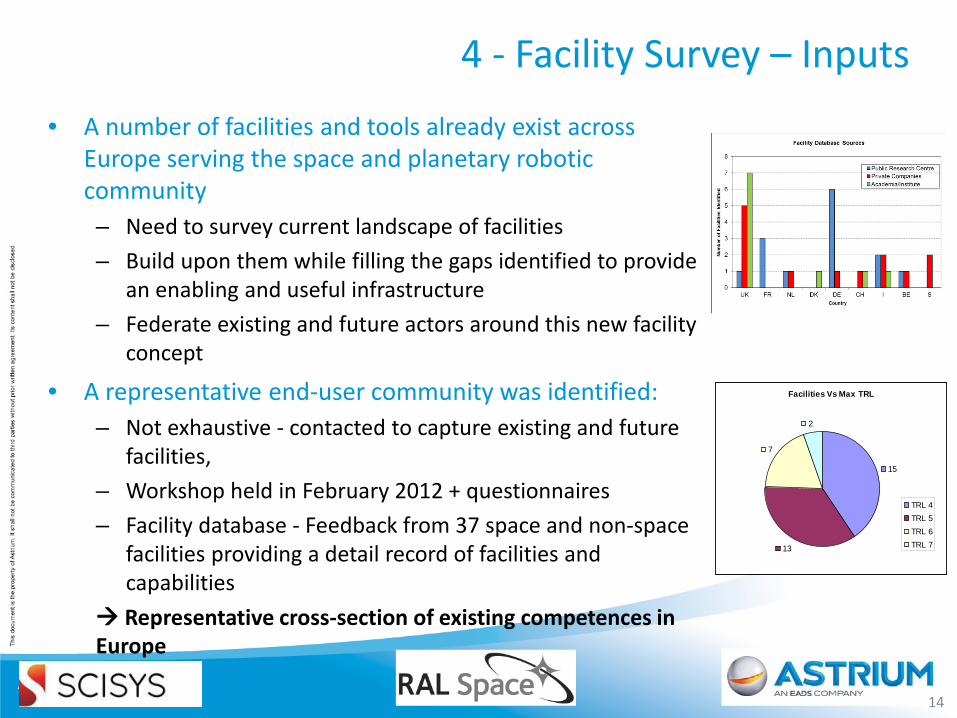
• A number of facilities and tools already exist across Europe serving the space and planetary robotic community – Need to survey current landscape of facilities – Build upon them while filling the gaps identified to provide
an enabling and useful infrastructure – Federate existing and future actors around this new facility
concept
• A representative end-user community was identified: – Not exhaustive - contacted to capture existing and future
facilities, – Workshop held in February 2012 + questionnaires – Facility database - Feedback from 37 space and non-space
facilities providing a detail record of facilities and capabilities
Representative cross-section of existing competences in Europe
14
Facilities Vs Max TRL
15
13
7
2
TRL 4TRL 5TRL 6TRL 7
4 - Facility Survey - Database
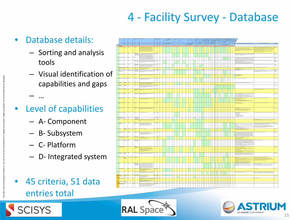
• Database details: – Sorting and analysis
tools – Visual identification of
capabilities and gaps – …
• Level of capabilities – A- Component – B- Subsystem – C- Platform – D- Integrated system
• 45 criteria, 51 data entries total
15
Name Institute Location Country Generic Type Summary description Space/Non-Space
Size of facility
Max TRL
Mec
hani
cal
Elec
trica
l / E
MC
/ ESD
Ther
mal
Vacu
um
Ligh
ting
Terra
in
Soil
and
Rock
s
Dust
Slop
es
Grav
ity (o
ffloa
d)
Haza
rdou
sPl
anet
ary
prot
ectio
n
Mec
hani
cal a
nd
Elec
trica
l Sup
port
Loca
lisat
ion
Envi
ronm
ent m
appi
ngEx
tern
al M
otio
n ca
ptur
eCo
mm
unic
atio
n an
d
Netw
ork
Virtu
al In
tegr
atio
nIn
tegr
ated
Sys
tem
Oper
atio
n Sc
hedu
ling
Inte
grat
ed S
yste
m
Oper
atio
n ex
ecut
ion
Virtu
al O
pera
tion
Rem
ote
Test
ing
Cont
rol
S/W
Rem
ote
Test
ing
Cont
rol
Cent
reIn
frast
ruct
ure
for m
obile
test
ing Fram
ewor
k In
stru
men
tatio
nCO
TS Q
ualif
icat
ion
Incr
emen
tal D
eplo
ymen
t Sa
nity
Che
ckin
g Fo
rmal
Ver
ifica
tion
Test
Dat
a Co
rrela
tion
Sub-
Syst
ems
Mod
els
Mec
hani
cal a
nd
Dyna
mic
sAp
plic
atio
nsNa
tura
l Phe
nom
ena
3D E
nviro
nmen
ts
Disc
rete
Eve
nt
Sim
ulat
ion/
Anal
ysis
Sim
ulat
ion
Mut
atio
n/Fa
ult I
njec
tion
Control And Operation Field-testingEnvironmental and Unit testing Specialist Facility Facility/Lab Infrastructure Comments. Provide details about specific facilities characteristic e.g. size Addition information/ More information from: source of information
Status
Total number of facilitiesfacilities
13 8 11 11 5 14 15 6 11 5 2 2 21 15 11 14 21 9 10 11 9 6 4 6 5 1 5 4 6 9 13 12 8 4 10 3 6
1 Astrium Mars Yard Astrium Ltd Stevenage UK Mars Yard The ASU instrumented Mars Yard was built as part of the ExoMars Rover Vehicle Project and is dedicated to the development of the Guidance Navigation & Control and Locomotion subsystems of the rover. The facility is designed to support a 300kg-class rover (approximately 1.6m long x 1.2m wide x 2m tall). It has been used to test the complete autonomous navigation system both at component level (eg. perception, trajectory control, etc) and as a complete system. It supports the use of optical sensors, IMUs and locomotion sensors, providing realistic responses in the rover. Additional facilities exist to support R&D / field trials.
Space medium 6 B B B B C C C C C C C C B D D C C C C C C C C C - Mars Yard with variety of sand types and rock sizes/shapes representative of ESA reference soils. - Various mechanical and electrical support features exist, including low voltage power supplies. - Localisation is accomplished by a ground truth system supplied by Inition Ltd. - Integrated systems (primarily Guidance Navigation & Control) are regularly operated in the area.- Field testing facilities (as used for UK and Tenerife trials with 'Bridget' prototype rover): mobile (+batteries) wireless links for basic remote control & monitoring, field trials equipmentPlanned 2012 - Lighting Q4,
To date, the facility has been primarily used (in a software sense) for the development of the autonomous navigation software for the ExoMars Rover. This has been at both component and system level. The focus has been to verify the equivalent simulator used by GNC. As a result, the main areas of use for the Mars Yard have been the dynamical response of the rover as it drives over the terrain and how this affects the autonomous navigation algorithms. In addition, it has also been used to test out the perception and navigation algorithms so the facility produces a sufficiently Mars-like landscape to confidence check the algorithms and verify the simulator. It is intended to extend this facility to a 30m x 14m sand terrain area, with representative lighting, in Q4 2012. This work will also include the build of a Control Room for EGSE equipment, functionally-representative rover elctronics models, and operators.
- Worshop- Questionnaire
2 Exploration Hall DFKI Bremen DE - Artificial Crater Landscape- Long Range Motion simulation Suystem
The crater landscape forms the lower portion of the space exploration hall (SEH). Spot lights with 6000K color temperature, high light intensity and nearly collimated incident angle. Accomodate medium-size systems.The Long range motion simulation system operates in the free space above the artificial crater. Its main parts are the cabled robotic platform ( workspace 6m x 4m x 4.50m (LxWxH), 150kg payload), the 6DOF robotic arm, the motion tracking system and the dSpace based control system.
Space & non-space
medium 4 C B C D D D D D D D D D As part of the Space Exploration Hall this facility can be combined with other systems like the Long Range Motion Simulation System as a support (e.g. VICON motion tracking, SpiderBot for gravity compensation) - The Long Range Motion Simulation System can be used as an augmentation for the artificial crater mobility testing environment.
Facility website: http://robotik.dfki-bremen.de/en/research/research-facilities/space-testbed.html - Workshop Presentation- questionnnaire
3 Virtual reality testbed DFKI Bremen DE The Virtual Reality Testbed is a projection environment with semicircular arranged display surfaces and 3D capability. 16 Render Clients and Master plus Server run VEROSIM a simulation environment with full physics simulation and robot control interface. Manipulation of viewport, environment and agents is possible through data glove and hand/headtracker or others.
5 D D D D C D Current configuration incorporates a large multi-panel projection facility, CyberTouch data gloves, InterSense head/hand tracking, 3D mouse and game pad. The simulation environment VEROSIM can provide several terrains and phsical properties (e.g. reduced gravity). It can instantiate robotic agents with physical properties. DFKI's MONSTER framework is able to control these robotic agents like a real robot. Environment, agent and the user's viewport can be manipulated by hand movement or any other HID device.
Facility website: http://robotik.dfki-bremen.de/en/research/research-facilities/virtual-reality-lab.html - Workshop Presentation- questionnnaire
4 Rover Track DFKI Bremen DE Rover test Track - Motor HIL testbench
The Rover Test Track is an outdoor obstacle course with 15 obstacle types, stretching 70m long and 6m wide. It is completed by a pond for testing of rover capabilities in wade, swim and submerged operations. Accomodate small to medium-size systems.
Space & non-space
medium 4 B B C C B D Obstacle types include: Wooden Staircase, Concrete Tube, Rock Hill, Cattle Bridge, Rock Canyon, Grass Dunes, Large Rock Field, Small Rock Field, Random Stepping Field, Gap Tester, Log Pile, Gravel Field, Railroad Tracks, Climbing Fence, PondAdditional test bench include hardware in the loop motor test bench based on two dSpace components. One is a MicroAutoBox II for hardware-in-the-loop software rapid prototyping. It can be seen as a smart PLC where robotic components can be controlled, observed or emulated. The second is a DS1006 quad core Processor Board with DS2202 HIL I/O Board.
Facility website: http://robotik.dfki-bremen.de/en/research/research-facilities/robot-testtrack.html - Workshop Presentation- questionnnaire
5 Underwater Testbed DFKI Bremen DE Lunar simulation/ Underwater/Rover test Track
DFKI's underwater testbed consists of two water tanks, 20 (opaque walls) and 40 (glass walls) cubic meter resprectively, in one building. 1 gantry crane with 150kg max. load and 1 slewing crane with 250 kg max. load allow lifting and lowering of payloads. The facility is considered for Weightless Environment Testing (WET) with less than neutral buoyancy.
Space & non-space
medium 5 C D D D D Facility website: http://robotik.dfki-bremen.de/en/research/research-facilities/underwater-testbed.html - Workshop Presentation- questionnnaire
6 European Space Tribology Laboratory
ESR Technology Ltd
Warrington UK Space tribology testing
- Tribometers for the generation of fundamental friction and wear data- Comprehensive range of dedicated test facilities- Supporting equipment, instrumentation and IT
Space Medium 6 B B B B B - Tribometers for the generation of friction and wear data - Physical vapour deposition chambers for applying solid lubricant - A range of 19 vacuum chambers from 150 mm to 1 m, with working temperatures from -150 to +150 C to test mechanisms and their components
http://www.esrtechnology.com/centres/estl/Pages/default.aspx'
7 LAMA DLR Bremen DE Planetary Surface Soil bin with gravity offloading Space Medium 5 C B B B C B B B B - Provides drop test capability- Single wheel testbed
LAMA-DLR-RY-0001
8 Planetary Exploration Laboratory - PEL
DLR Oberpfaffenhoffen, DE DE Instrumented Indoor Mars Soil bins
Instrumented soil bin - Facility for LSS testing during ExoMars phase B2X2 LSS testing, dedicated to mobility investigations, rover performance testing, control algorithm testing
space medium 5 B C C B B D D D D C B B B B http://www.dlr.de/en/desktopdefault.aspx/tabid-24/82_read-2669/Paper M.Apfelbeck- "NOVEL TERRAMECHANICS TESTBED SETUP FOR PLANETARY ROVER WHEELSOIL INTERACTION"
- Workshop- Questionnaire- Papers
9 EADS-IW Power Lab EADS-IW NewPort, UK UK Indoor Lab A HITL Enviroment for evaluating current and future power architectures. This system is also used for the development of novel power managment techniques
Non-space medium 5 D D D D D D C 10 kW of Programable power supplies3 kW of programmable loadsHITL test enviroment for power loads Fuel Cell Test Chamber
Questionnaire
10 Bristol Robotics Lab Bristol University Bristol, UK UK Indoor Lab Large robotics laboratory funded by both Universities in Bristol. Focus is on service robotics, swarm robotics, robot energy autonomy, wheeled/walking/flying and underwater robots.
Non-space medium 4 B B B B D Some remote testing capability existing at subsystem level Questionnaire
11 Off-Road Dynamics Facility
Cranfield University
Cranfield UK Indoor instrumented facility
Controlled environment off road characterisation and test facility from small scale (Mars Rover wheels) to large scale and whole vehicle test and measurement. Test services support by modelling and simulation expertise including FE and SPH solutions for a range of off road surfaces.
Non-space medium 4 D D D B B - Small soil tank also incorporates a gravity offload (counterbalance) system.- Soils laboratory also available for mechanical testing (direct shear or Triaxial) of soil materials.
Questionnaire
12 Department of Computer Science
University of Liverpool
Liverpool UK Simulation facility The academically focussed Centre for Autonomous Systems Technology, (together with the industry-facing Virtual Engineering Centre, at the Daresbury Science and Innovation Campus), provide a facility for the comprehensive design, high-fidelity simulation, validation, testing, and formal verification of autonomous systems.
Space & Non-Space
Academia 4 D D D D D D D D D D D D D D Questionnaire
13 Mobile Robotic Group University of Oxford
Oxford UK Test platform, sensor Calibration and navigation
Two labs, one in Oxford and one at Begrboke Science park, 5 functional robots (20kg to 2000kg (and autonomous car) and soon another 2 all electric autononous cars
Non-Space Academia 4 C C C C C C D D D D D I expect to expand the grou to about 30 individuals with a year or two. Videos and details can be found on our webpage www.robots.ox.ac.uk/~mobile
Questionnaire
14 Autonomous System lab
University of Surrey
Guildford UK Instrumented Lab and test platforms
The lab consists of multi-terrain yard, 3D tracking system, multiple micro-rover platforms with standarized mid-ware interfaces, soil drilling testbed, single wheel and single leg test rigs etc
Space Academia 4 B B B C C C C C C C C C D D C C C C Hardware - - Walk in thermal chamber -30 - +70 deg C, - 1 cubic Metre Vacuum chamber - 1E-7 Torr, - Platforms: 3 Pioneer 3AT mobile robots and 1 Coroware Explorer mobile robot equiped with field monocular camera and Hokoyo LIDAR Software - - standarzied mid-ware protocol for modular s/w integration and testing, autonomous s/w architecture, fully integrated s/w system withsensor/actuator interfaces Multi-rover testbed for modular autonomous software; drilling testbed, single wheel test rig and a three degree of freedom single leg test rig, Characterisation of planetary soil simulants. Additional facilties are available at the Geotechncial lab. This includes equipment for shear test, resin impregnation, pressure-sinkage test etc.
-Workshop - Questionnaire
15 SEROM - Outdoor Mars Yard
CNES Toulouse FR Mars Yard Large Outdoor mars yard and suite of software for the localisation of the moving platform and the mapping of the terrain. This facility has been used to perfrom a teleoperation test from ESTEC.
Space Large 5 B B B B D C C D D D D D C C C C C B B B C B C B D B - perception
Large Mars Yard covered with lightweigh volcanic material- Site webcam on an extendable mast.- DGPS for cm accuracy- laser Tracker for higher accuracies available- DEM of site at various resolutions (plane - 5cm and higher with laser scanner)- Process in place for operation of laser tracker, laser data management and post-processing.- From experience, 80m traverse leads to ~300MB of data
Paper, Joudrier et al - "ESTEC-CNES ROVER REMOTE EXPERIMENT" -Visit- Questionnaire
16 SEROM - indoor mars Yard
CNES Toulouse FR Mars Yard Medium size Indoor yard, no indoor localisation Space medium 5 D C C D D D D D C C C C - Indoor facility, artificial lighting- same surface material as outdoor Mars Yard
Paper, Joudrier et al - "ESTEC-CNES ROVER REMOTE EXPERIMENT" -Visit- Questionnaire
17 Stereo Calibration bench
CNES Toulouse FR Stereo Calibration Bench
Eextensive test setup to calibrate stereo benches (2 benches + 1 scene). Include suite of software to compare stereo data with laser scanner 3D data. A laser tracker is also avaialble for highly precise measurements and calibratoin.
Space 5 B B B B B B The Facility consist of :- a 5m x 5m test area with geometric and natural objects, Faro laser tracker (<1um )and laser scanner (~30um, <1mRad)- 2 benches for camera calibration (1 with collimator ) and associated software- Set of software developed to validate stereo reconstruction against laser data- Some lighting for high contrast camera testing ( component level)
-Visit- Questionnaire
18 MTS - Mars Terrain ALTEC Turin I Mars Yard Facility aimed at functional tests for rovers Space medium 4 D C D Terrain area is 18x 19 meters, improvenets in terms of slopes, rocks, Planned activities and level:- D - Gravity offloading- D - Localisatoin- D - environment mapping- D - External Motion Capture (see Note 1)- D - Integrated System Operation Scheduling- D Integrated System Operation execution- D - Virtual Operation
(1) 3D map done with the support of an external company (a 3D laser scanner available in TAS) Workshop-Visit- Questionnaire
19 Neutral Buoyancy Testing Facility - NBTF
ALTEC Turin I Underwater/low gravity testing facility
Space Medium 5 D D
20 VNTF TAS-I Turin I Aerial Platform testing environment
The test area consists of a wire cage 8.5 x 8.5 x 8.5 m. It has a set of Vicon IR cameras for localisation to ~ mm accuracy and banks of lights on one side.The base is a Martian-like terrain with small-scale features (rocks, hills)
Space Medium 4 C C C C C C - A 8.5m cubed area, approximately, in the form of a test-cage with cameras, lights. Used for testing EDL using aerial platform models.- Currently this is used for TAS' internal R&D work, but could be made available to external users.
-Visit
21 Locomotion Subsystem Test Facility
RUAG Zurich CH Instrumented Mars soil bins
Laboratory room controlled in humidity that accomodate:- ESA System Level testbed for testing rover on soils and obstacles- Highly accurate single wheel test facility (flexible and rigid wheels)- Various Martian and a Lunar soil are available- Locomotion SS 3D parametrical tool (correlated with ExoMars BB)
Space Medium 6 B B B B C B B B B B B B B B B C C - see 1
C - See 2
C - See 3 C - See 4 Notes: 1 - Quasi-static tool that simulate motor dynamic but do not handle shock comming from the terrain. CAD model cannot be directly imported but the parameters easily adjusted to fit the model or H/W. 2 - DEM can be imported and a soil map linked to a database for importing any required soil parameters.3 - Simulation at least 2x faster than reality on a standard PC. Achieved trough pre-propressing of soil-wheel interaction data.4 - Blocked wheel can be simulated. Terrain can be modified dynamically in terms of elevation and soil properties (for example multipass is considered).- Tool running on any PC under Windows XP
Test: The test facility was extensively used in the frame of various ESA projects like RCET and ExoMars locomotion S/S and will be used for HDPC. It has successfully passed the TRR. An extension of the single wheel testbed is already implemented and commissioned. The tools for soil preparation/monitoring will be extended and additional soils procured in a near future.
Simulation: the analytical tool developed for supporting the co-engineering phase of the ExoMars locomotion S/S was significantly extended and includes DEM and soil map, interface single wheel test data or wheel level simulation. It can simulate ExoMars, MER and NEXT rover locomotion S/S. 3D visualization is available using Ogre3D (same as used in 3DROV).
- ESA facilitues PDF 7/3/12 (TJ)- Questionnaire
22 PATLab Aberystwyth University
Aberystwyth UK Mars yard Planetary Analog Terrain Laboratory Space Medium 5 D C B C C C D D D D D D D D D Calibration - PanCam Radiometric and colourimetric calibration Facility- Proximity of Clarach Bay for filed trials e.g. FP7 ProvisScout- Platforms available - 1/2 exoMars chassis, IDRIS quad-based rover
-Workshop
23 Planetary Robotics Testbed
ESTEC Noordwijk NL Instrumented Mars Yard
Indoor terrain ~ 9m x 9m, Basaltic gravel + boulders and red loamVarious models of rovers (most reduced scaled) Laser scanning system (Riegl), High accuracy localization system (VICON)Used internally for engineering assessment and technical awareness. 3DROV simulator, prototypes of control stations
Space Medium 4 C C C C C C C D D D D D D D D The facility is mainly used to support the testing of relatively modest inhouse developments to assess the potential of technical solutions and for the acceptance, testing and demonstration of deliverables of externally performed R&D work, related to various aspects of the control and operations of robotics systems for planetary surface missions. The scope/level can vary from e.g. navigation/localization algorithms/sensors to functional testing of models of subsystems (e.g. locomotion), to integrated ones involving a number of platform as well as instrument/payload functions. The terrain has a limited degree of physical representativeness of a Martian surface. Computer simulation of the robotic system and its operating environment are performed by means of 3DROV.
Website: www.esa.int/TEC/Robotics/SEMUB68LURE_0.html -Workshop- Questionnaire
24 MarsLab - European environment Simulator
Aarhus University Aarhus DK Atmospheric and Dust simulation
Main simulation chamber ;- Pressure, Temperature (100K – 350K), Humidity control, Wind speed- Dust aerosol, Controlled Dust Exposure (>300 sol)- Optical (and UV) ‘solar simulator(s)’
Space, Small / Medium
6 D D D D D D D - Pressure 0.02-1000 mbar (pumping 10mbar 25mins) Gas (Air, CO2, N2, etc..)- Temperature (100K – 350K) [Humidity control]- Wind speed 1 - 25m/s (low P)- Dust aerosol ≈ 1-1000 cm-3 , Controlled Dust Exposure (>300 sol)- Optical (and UV) ‘solar simulator(s)’ - Dust analogues, laser measurement of wind speed and dust deposition/concentration
-Workshop
25 Oxford technology Ltd Oxford technology Ltd
Abindgon UK Remote handling, Dextrous robotics
Remote Handling and robotics for hostile environments. Medium 5 B D D D D D D - OTL's facilities are primarily related to the development and testing of highly dexterous robotic systems and robotic movers used for remote handling in hostile environments. This includes the development, build, testing and characterisation of actuator systems, control systems and human-machine interface (HMI) software. Many of these robotic systems are used in safety critical situations and therefore require extensive validation and testing prior to deployment in the field. - OTL has a particular focus on the execution of highly complex remote tasks. To that end we have developed and have extensive use of virtual reality simulations involving the use of robotic devices in complex ‘real-time’ environments.- OTL operate a full remote control room with video wall, external camera feeds and robotic haptic master linked to our external robot test yard (200m sq) for testing and validation of robotic devices and for development and validation of complex remote tasks.
Website - http://www.oxfordtechnologies.co.uk/ Questionnaire
26 Planetary Environment Simulation Chambers
Open Univesity Milton Keynes UK Planetary Environment Simulation Chambers
Two distinct areas of simulation: Environmental exposure, Dynamic processesState-of-the-art of planetary simulation chambers providing • Simulated martian environmental conditions, including temperature, pressure, atmospheric composition and solar UV illumination conditions. • Thermal cycling qualification of components to ECSS standards.• DHMR sterilisation as per COSPAR protocols.A range of sizes of chamber are available to enable cost-effective and precise testing of parts, components and assemblies. • Micrometeoroid impact
Space Small 6 D D D D D D - Mars environment chambers: Pressure 6-10 mbar, Temperature: 200-290 K, Illumination: UV lamp, Capable of cycling (day/night simulation)- Long Term exposure - e.g. Bepi Colombo components Qual - Item was exposed to a thermal environment of +110°C at ambient pressure for 28 days.- Icy Bodies and Space env simulation - Moon, Europa, Ganymede - Low pressure and temperature. Pressure: <10-5 mbar (1 mPa), Temperature: 120 - 420 K, Chamber size ranges from 14 to 70 cm diameter- Micrometeoroid Impact Simulation - Light Gas Gun, Fires projectiles (up to 4mm) into targets, Impact velocities of up to 5 km/s- Van de Graaff accelerator, Accelerates many ~5 μm-sized iron particles through an electric field towards a target, Velocities of many 10s km/s
- workshop- Questionnaire
27 Advanced Space Concepts Lab
Strathclyde University
Glasgow UK Autonomous control - activities in Swarm control, landing site selection, descent controller, mole- verifying the developed single/multi-robot control algorithms in a lab environment
Space Small 4 D D D D D D D - VICON T160 Motion Capture System (6 camera T160 (16 megapixel) system with overlaid video, providing real time object tracking in 6 DOF at 120 frames per second at full resolution. )- Leica Absolute Tracker AT901 B - A ruggedised and portable optical laser tracker with a 360o horizontal, ± 45o field of view, range of 0-40 m, angular resolution of 0.14 arc sec, and angular accuracy of ± 15 μm + 6 μm/m.
-Workshop- questionnaire
28 RAL Space Robotics Rutherford Appleton Laboratory
Harwell Oxford, Didcot UK Mechanical Test Facilities
Space 5 D D D C B D C C D D D D - see 3
D D - see 4
1 - Mechanical workshop. Can do precision micro-machining. Very responsive in direct support of ongoing tests/trials.2 - Small Yard which has a variety of slopes and moveable rocks.- For Startiger SEEKER a number of modules are inetgrated from different companies. The yard has proved very useful in the evaluation of visual odometry, local DEM generation and path planning software at a level below that of a field trials. - For local field trials we have built up a relationship with a local quarry operator and have used this extensively.3 - UAV with gimbled camera system and associated DEM generation software. DEM provided to Rover for path planning & evaluation of route taken wrt obstacles. DGPS system capable of supporting two rovers at a site(10mm accuarcy)
- Extensive experience in hosting and serving to the scientific community data sets. These data sets use metadata to allow extration of specific products. - The Concurrent Design Facility with its dedicated server, storage, offlne networking, video conferencing and 25 seats control room can be used to complete spacecraft, robot, instrument or software design studies. The facility can be also linked up with similar establishments around the world such as the ESA CDF at ESTEC or NASA's Jet Propulsion Laboratory.It could be used as an "operations centre" during a field trial.
29 3DROV Trasys Hoeilaart BE 3DROV - Planetary Robot Design, Generic Visualisation and Validation Tool
3DROV is an integrated simulator to help assessment and verification at system level of planetary exploration missions. Such an integrated simulator is designed to be open and flexible to match the level of fidelity needed. It includes, at adequate level of representativity, all the components intervening to the execution of mission scenarios including: the onboard rover control software, the models of the rover and the instruments, the models of the environment in which the rover operates and with which it continuously interacts, and finally the ground control software and the 3D visualization tool. 3DROV is build up on the SIMSAT ESOC simulation framework.
4 D D D D D D D D D D D D D D The 3DROV simulator may be connected with a Ground Control StationFormal specification and verification is performed using the Esterel programming language and the associated tools Discrete event simulation can be performed at Activities level but not yet at global simulation level (e.g. including models of the subsystems). This functionality is an on-going work.
3DROV has been instantiated for ExoMars. It is currently instantiated for the Lunar Rover Model (LRM) rover located at ESTEC laboratories3DROV is used as simulator in various ESA TRP activities in connection with Automatic Planners. 3DROV disposes a powerfull 3D visualisation component that is currently extended as a standalone Activity Plans specification and simulation 3D tool supporting simulated and real data analysis
-Questionnaire
30 Centre Spatial de Liége Angleur BE Test facilities CSL is one of the 4 ESA coordinated test facilities.The scope of activities and researches of CSL is divided in 3 main fields: - space testing for European Space Agency and space industry, - optical instruments development,- technological developments.
Space/Non-Space
Medium 6 D D D D B D http://www.csl.ulg.ac.be Website
31 Scisys Scisys Bristol UK Test platform Indie is a highly portable, space representative rover development platform used for technology development and demonstration in a range of in-door and out-door locations.
Space Small 5 D D D D C C C C C Indie has a mast with high resolution plus bumblebee camera systems, can carry a payload of approximately 10 Kg and has a LEON processor
Indie has been used in various Mars-yards eg RAL plus a number of quarries which are good Mars analogues. We have all required on-board and off board software (Overseer) and can rapidly integrate thrid party components (both hardware and software) as demonstrated through the SEEKER project.
32 Dutch Space Dutch Space Leiden NL mechanisms Design and testing
Design of Space Robotic manipulators Space Medium 7 D D D D
33 Drill testing Rig Selex Galileo I Drill testing - vertical test column (penetrator?)• 2m deep test column for drill testing in labconditions at Selex Galileo (I)
Space Small 5 B B - ESA facilitues PDF
34 Autonomous Systems Lab
ETH Zurich Zurich CH The ASL is a laboratory consisting of the former Center of Product Design (ZPE) from ETH Zurich and the Autonomous System Lab from the ETH Lausanne (EPFL).The Autonomous System Lab carries on research in mobile robotics and Mechatronics, namely in the design and control of systems operating in uncertain and highly dynamical environments
Space/non-Space
Medium 4 http://www.iris.ethz.ch/
35 Drill testing Rig University of Padova
I • Facility for Drill tests in Mars-like environment (Tgradients,low pressure)
Space Small 4
36 IABG DE 7 D D D D37 Space PET - Planetary
Exploration Test-BedGMV SP Area of 180m2 simulating a Martian landscape with red soil similar in
granulometry to the Martian soil, rocks and a Mars panorama. This facility provides a large test area and an outdoor environment to test different robotic applications under natural lighting conditions. The soil characteristics are matched to some regions on Mars, and the rock colors, sizes and distribution are intended to match images from Martian missions.
Space/non Space
Medium 4
Simulation & Modelling relatedHardware related facilies
Control And Operation Field-testingEnvironmental and Unit testing Specialist Facility Facility/Lab Infrastructure
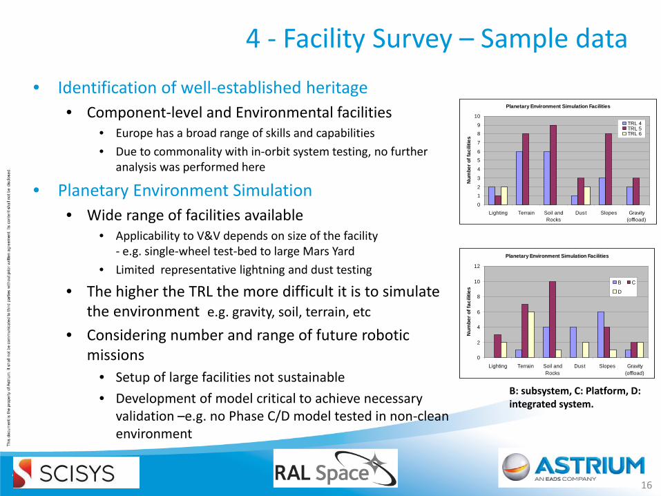
4 - Facility Survey – Sample data • Identification of well-established heritage
• Component-level and Environmental facilities • Europe has a broad range of skills and capabilities • Due to commonality with in-orbit system testing, no further
analysis was performed here
• Planetary Environment Simulation • Wide range of facilities available
• Applicability to V&V depends on size of the facility - e.g. single-wheel test-bed to large Mars Yard
• Limited representative lightning and dust testing
• The higher the TRL the more difficult it is to simulate the environment e.g. gravity, soil, terrain, etc
• Considering number and range of future robotic missions
• Setup of large facilities not sustainable • Development of model critical to achieve necessary
validation –e.g. no Phase C/D model tested in non-clean environment
16
Planetary Environment Simulation Facilities
0
1
2
3
4
5
6
7
8
9
10
Lighting Terrain Soil andRocks
Dust Slopes Gravity(offload)
Num
ber o
f fac
ilitie
s
TRL 4TRL 5TRL 6
Planetary Environment Simulation Facilities
0
2
4
6
8
10
12
Lighting Terrain Soil andRocks
Dust Slopes Gravity(offload)
Num
ber o
f fac
ilitie
s
B C
D
B: subsystem, C: Platform, D: integrated system.
4 - Facility Survey – Infrastructures
• Facilities Infrastructure to support System Level V&V – As system evolves from low to high TRL – Need for a range of software
and hardware facilities required from prototyping to validation – From survey feedback, Simulation and Modelling environment seen as
major catalyst: • To reduce development cost across development stages • …as TRL is raised, so will the accuracy of the simulation
Correlated and calibrated simulation models are required: with data generated from real hardware during tests and field trials ultimately contribute to the validation of the integrated system at flight
readiness Need an infrastructure that allows : the integration of subsystems model that exist across the community, the virtual integration of robotic and payload systems into an accurate
simulated environment
17
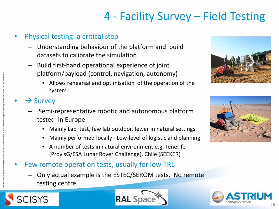
4 - Facility Survey – Field Testing • Physical testing: a critical step
– Understanding behaviour of the platform and build datasets to calibrate the simulation
– Build first-hand operational experience of joint platform/payload (control, navigation, autonomy)
• Allows rehearsal and optimisation of the operation of the system
• Survey – Semi-representative robotic and autonomous platform
tested in Europe • Mainly Lab test, few lab outdoor, fewer in natural settings • Mainly performed locally - Low-level of logistic and planning • A number of tests in natural environment e.g. Tenerife
(ProvisG/ESA Lunar Rover Challenge), Chile (SEEKER)
• Few remote operation tests, usually for low TRL – Only actual example is the ESTEC/SEROM tests, No remote
testing centre
18
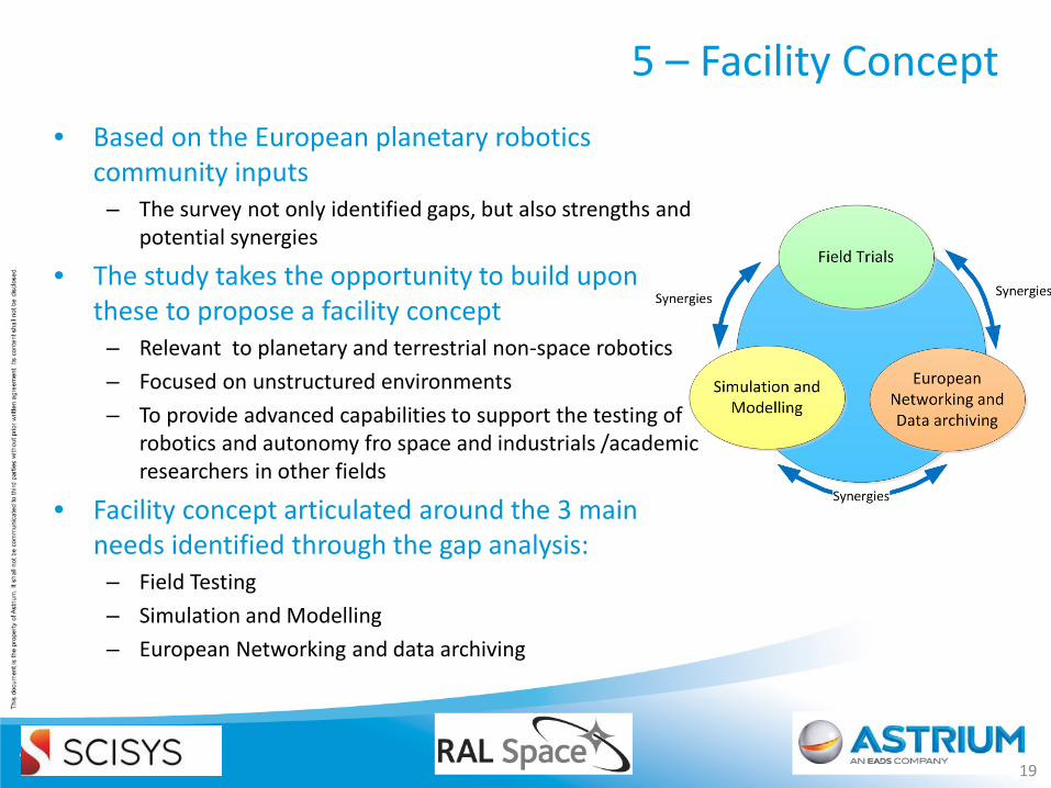
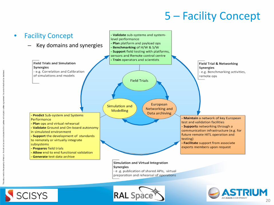
5 – Facility Concept • Based on the European planetary robotics
community inputs – The survey not only identified gaps, but also strengths and
potential synergies
• The study takes the opportunity to build upon these to propose a facility concept
– Relevant to planetary and terrestrial non-space robotics – Focused on unstructured environments – To provide advanced capabilities to support the testing of
robotics and autonomy fro space and industrials /academic researchers in other fields
• Facility concept articulated around the 3 main needs identified through the gap analysis:
– Field Testing – Simulation and Modelling – European Networking and data archiving
19
5 - Facility Concept
• Field Trial support unit – Focus on integrated hardware testing (platform + payload), autonomy
validation, and surface operations rehearsal and validation. – Answers community needs to have access to a set of reference platforms
• with published Application Programming Interface (APIs) • to benchmark and test autonomy functions easily and rapidly
– Facilitate the setup and running of field trials, technically and logistically • Provide reference and metrology instrumentation e.g. site mapping • Provide and maintain accurate test site database in Europe and beyond
Acquisition of critical data for the correlation of simulation models – A Remote Robotic Operation Centre at the facility
• to enable remote testing and the setup of realistic operation scenario • To help validate operational concepts during trials
Field Trial
5 - Facility Concept
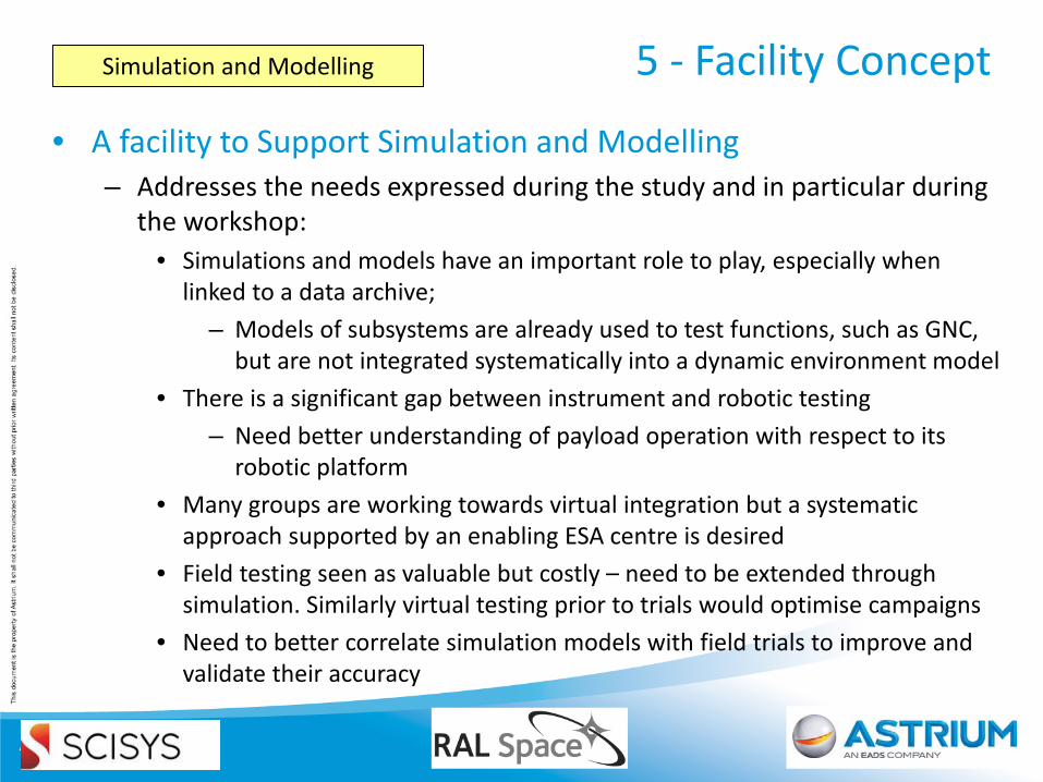
• A facility to Support Simulation and Modelling – Addresses the needs expressed during the study and in particular during
the workshop: • Simulations and models have an important role to play, especially when
linked to a data archive; – Models of subsystems are already used to test functions, such as GNC,
but are not integrated systematically into a dynamic environment model • There is a significant gap between instrument and robotic testing
– Need better understanding of payload operation with respect to its robotic platform
• Many groups are working towards virtual integration but a systematic approach supported by an enabling ESA centre is desired
• Field testing seen as valuable but costly – need to be extended through simulation. Similarly virtual testing prior to trials would optimise campaigns
• Need to better correlate simulation models with field trials to improve and validate their accuracy
Simulation and Modelling
5 - Facility Concept
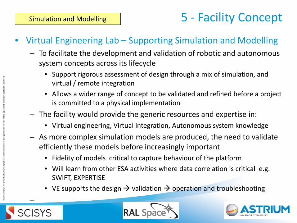
• Virtual Engineering Lab – Supporting Simulation and Modelling – To facilitate the development and validation of robotic and autonomous
system concepts across its lifecycle • Support rigorous assessment of design through a mix of simulation, and
virtual / remote integration • Allows a wider range of concept to be validated and refined before a project
is committed to a physical implementation – The facility would provide the generic resources and expertise in:
• Virtual engineering, Virtual integration, Autonomous system knowledge – As more complex simulation models are produced, the need to validate
efficiently these models before increasingly important • Fidelity of models critical to capture behaviour of the platform • Will learn from other ESA activities where data correlation is critical e.g.
SWIFT, EXPERTISE • VE supports the design validation operation and troubleshooting
–
Simulation and Modelling
5 - Facility Concept
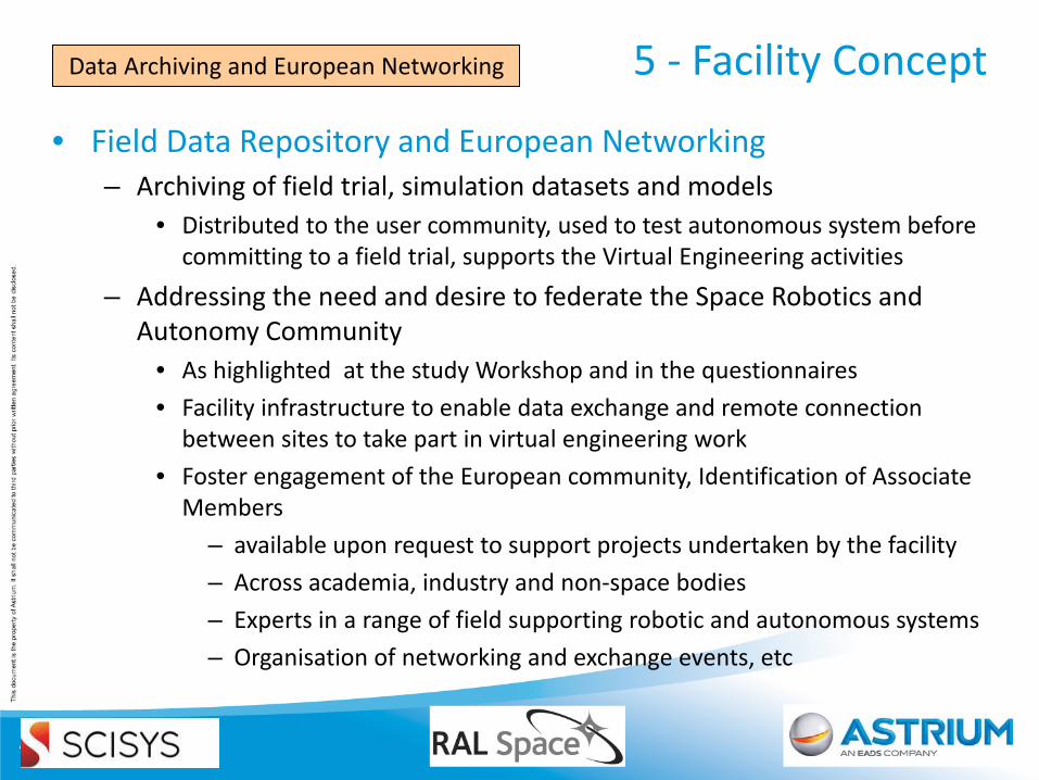
• Field Data Repository and European Networking – Archiving of field trial, simulation datasets and models
• Distributed to the user community, used to test autonomous system before committing to a field trial, supports the Virtual Engineering activities
– Addressing the need and desire to federate the Space Robotics and Autonomy Community
• As highlighted at the study Workshop and in the questionnaires • Facility infrastructure to enable data exchange and remote connection
between sites to take part in virtual engineering work • Foster engagement of the European community, Identification of Associate
Members – available upon request to support projects undertaken by the facility – Across academia, industry and non-space bodies – Experts in a range of field supporting robotic and autonomous systems – Organisation of networking and exchange events, etc
Data Archiving and European Networking
5 - Facility Concept
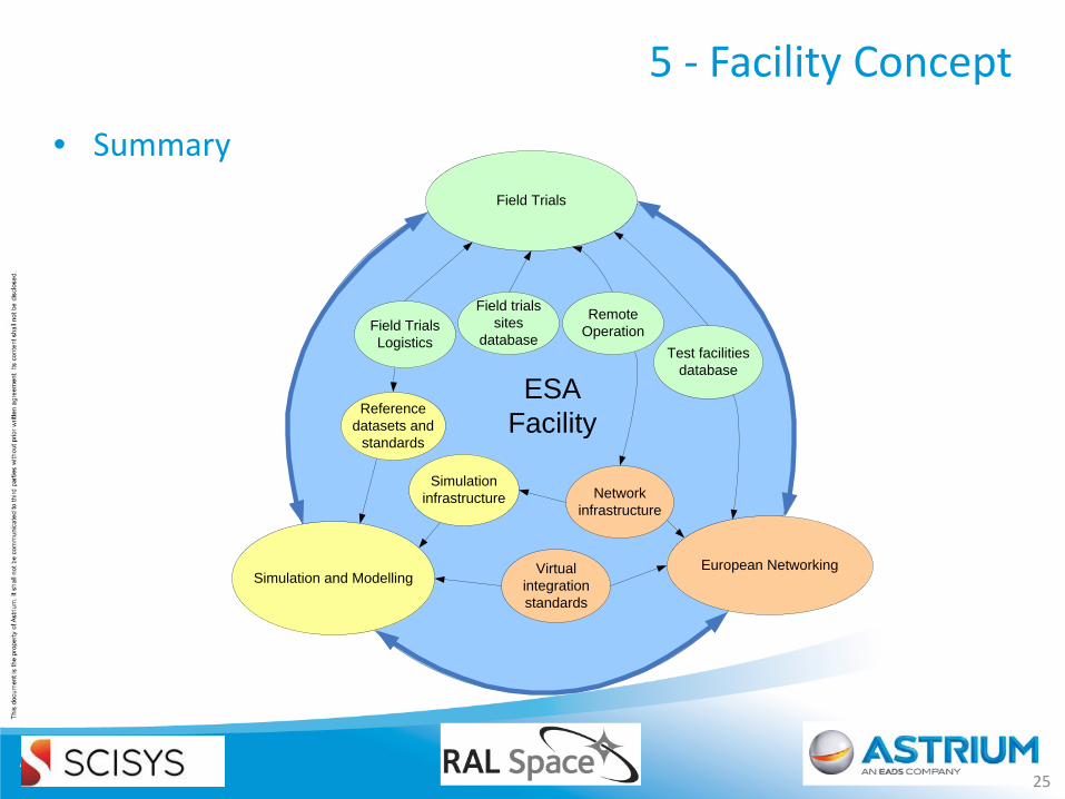
• Summary
25
Field TrialsLogistics
Simulation infrastructure
Virtual integration standards
Test facilities database
Field trials sites
database
Field Trials
Simulation and ModellingEuropean Networking
Network infrastructure
Reference datasets and
standards
ESA Facility
Remote Operation
6 - Implementation
• A phased implementation – Anticipated to be established through the setup and demonstration of its
various elements – Through a number of Pilot Projects
• Aiming at demonstrating how the engineering processes of a fully operational facility would work using existing facilities (HW/SW)
– Proposed scenarios - Still TBD • Representative of Planetary Exploration Mission derived from ESA Mission
Roadmap • Exploit hardware and autonomous software to exploit correlation of data
generated by Virtual and Physical engineering • Develop complementary capability to the current Mars Robotics Exploration
Programme (MREP)
7 – Supporting R&A systems beyond Space
• A versatile facility: – Primarily a facility supporting the need of the European space
community for planetary exploration – Also highly relevant to applications beyond the space sector
• Could generate valuable synergies with non-space markets that would ultimately benefit the space industry
• Gathering and sharing best practices, processes, tools and methods
• Specific opportunities already identified from large systems integrators to SMEs and academia, – Agriculture, Assisted Living/Health, automotive, Construction , Nuclear
Power Decommissioning • The facility could provide network of tools and experts
– To provide independent validation of R&A system – Certifications? • Shortens time to market
8 - Conclusion
• The study: – Investigated the feasibility for V&V facility focused on Robotic and
Autonomous Planetary Systems – Reviewed existing facilities and capabilities across Europe, captured
anticipated requirement from a cross-section of the user community
• Synthesis of a Facility concept – Addressing 3 key domains and capitalising on their synergies
• Field trials, Simulation and modelling, Networking – Involving local experts and the community at large – To further the methods and processes involve in developing R&A system
and making them more robust – To support and foster cross-sectorial applications in and beyond the
space market – Following this study, pilot projects currently at the planning stage
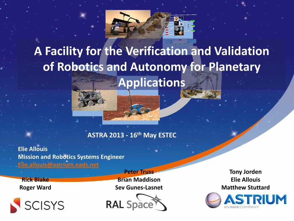
Elie Allouis Mission and Robotics Systems Engineer [email protected]
Rick Blake Roger Ward
Peter Truss Brian Maddison
Sev Gunes-Lasnet
Tony Jorden Elie Allouis
Matthew Stuttard
A Facility for the Verification and Validation of Robotics and Autonomy for Planetary
Applications
ASTRA 2013 - 16th May ESTEC


![Semi-Analytical Guidance Algorithm for Fast Retargeting ...robotics.estec.esa.int/ASTRA/Astra2013/Presentations/Lunghi_28245… · TLS [0,0,0] m (NLS) TLS [0,-1000,0] m • Landing](https://img.pdfslide.us/doc/110x75/5f77b97e2b0d7c75c35bf79e/semi-analytical-guidance-algorithm-for-fast-retargeting-tls-000-m-nls.jpg)