Embed Size (px)
Citation preview

A E R 0 5 P A C E
.. UNITED STATES AIR FORCE MARCH 1963
..
I

* DIG SAFETY REORGANIZED *
Brigadier General Bertram C. Harrison
Deputy The Inspector General, USAF
Brigadier General Henry C. Newcomer
Director of Inspection
AS OF 7 JANUARY 1963, the office of the Deputy Inspector General for Safety underwent a change in organization and designation. This is part of a general reorganization of The Inspector General's office concerning the staffs of Deputy Inspector General for Inspection and Deputy Inspector General for Safety. T'hese activities are now placed under one head, the newly established Deputy The In pector General with offices at Nvrton AFB. The DIG/ Inspection and DIG/ Safety designations no longer apply. Three Directorates have been established under the Deputy The Inspector General. These are the Directorate of Inspection, the Directorate of Nuclear Safety and the Directorate of Aerospace Safety. The Directorate of Nuclear Safety is located at Kirtland AFB, New Mexico.
Three Divi ions and three Groups are organized under the Director of Aerospace Safety. These are the Flight Safety Division, the Ground Safety Division and the Missile Safety Divi ion supported by the Education & Training Group, the Life Sciences Group and the Records & Statistic Group.
Major General Charles W . Schott was assigned as the Deputy The Inspector General on 8 January 1963 . He retired from active duty on 31 January 1963. Deputy The Inspector General i now Brigadier General Bertram C. Harrison.
The Director of Inspection is Brigadier General Henry C. Newcomer; the Director of Aerospace Safety, Brigadier General Jay T. Robbins; the Director of Nuclear Safety is Colonel Charles B. Stewart.
Under the Director of Aero pace Safety, Colonel Charles L. Wimberly heads the Flight Safety Division; Colonel Earl S. H owarth, the Ground Safety Division; and Colonel George T. Buck, the Missile Safety Division. Colonel J erome I. Steeves is Chief of the Education & Training Group; Colonel Emmert C. Lentz, Chief of the Life Sciences Group; and Mr William Russler, Chief of the Records & Statistics Group. *
Colonel Charles 'B. Stewart
Director of Nuclear Safety
Brigadier General Jay T. Robbins
Director of Aerospace Safety
Col Charles L. Wimberly Chief, Flight 'Safety Division
Colonel Paul P. Douglas, Jr Deputy Director of Aerospace Safety
Col Jerome I. Steeves Chief, Education &
Training Group
Col Earl S. Howarth Chief, Ground Safety Division
Col Emmert C. Lentz Chief, life Sciences Group
Col George T. Buck Chief, Miss ile Safety Division
Mr. William Russler Chief, Records & Statistics Group
1
•
•'
Lieutenant General W. H. Blanchard The Inspector General, USAF
Brigadier General Bertram C. Harrison Deputy The Inspector General, USAF
Brigadier General Jay T. Robbins
Director of Aerospace Safety
Colonel Charles L. Wimberly
Chief, Flight Safety Div ision
Colonel Earl S. Howarth
Chief, Ground Safety Divis ion
Colonel George T. Buck
Ch ief, Missile Safety Division
•
IN THIS ISSUE DIG Safety Reorganized .................... ..IFC
Fall out ·····------ -· -·------------------ ____ __ ___ __ ____ __ 1
Swept Wing Savvy ------- --- --- ------- -- -- ----·· 2
If You Fly At Night -- --- --- -------- --- -- ------- -- 6
The Hot Seat ····------····----- -- --------- -------- -- 7 When a Prop Runs Away ____________________ 8
Lightning Protection __________________________ __ 11
Zero Second lanyard __ _____ __ _______________ __ 14
Cross Country Notes _______ ____ __ ____ _______ ___ .16
Ride The Wild Horse {Part Two) _____ ___ 18
Missilanea ------------ ------------- ------------ ------.22 Pistols Are Not Playthings ____ ____ ______ ____ 23
Is Your Notam Showing? ___ _________ ____ ____ 24
Aerobits ···----------- --- -------- ---- -- -·------------- --26
What I Saw! ·--·---- ---- -- ----- --- ------·----- --------29
Chief, Education and Training Group
Colonel Jerome I. Steeves
Featu re Ed itor
Amelia S. Askew
FALLOUT T -Bir·d Talk
Rex Riley's Cross-Country Notes usually afford us T-33 drivers several items of unusual interest and the November issue was no except ion. However, I believe that to be of greater value, the paragraph " T-Bird Talk" might be expounded upon.
After reading the cited incident of static port icing, I checked the Dash One for information that would be a help if our pilots were faced with a similar situation. There wasn ' t much help there, nor did Rex Riley offer any advice except, "Give it some thought when you are faced with a low speed radar approach during icing conditions."
The story didn't elaborate as to w hether nig ht or daylight cond it ions p revailed, if the pilots noticed any ice on the aircraft, or what the fuel load was. It would seem tha t in icing conditions (to include runway ice). a pilot would not be wise to maintain much more than 130 knots, unless he was near stall condition s, if he expected to stop on the runway.
6o, what is the answer to t he problem? The first answer would be : don' t fi le into f reezing rain condit ions unless the mission absol utely req uires that such a fl ight be made. Secondl y, th e Dash One (page 3-33) gives an alternative: '' If rime ice is present (or presumably clear ice •also). use power rathe r than airspeed as a refere nce while flying the landing pat•tern ."
But-isn't this statement a littl e nebulous? All solutions seem to boil down to judgment and technique during a critical phase of flight such as this. Pilots of all types of aircraft must depend on experience, judgment and technique in such instances.
Maj James P. McMullen Director of Safety Boll ing AFB, 25, D. C.
Major, yon said it all in the last paragraph.
Feathe r Inboard Props After a careful sc ruti ny of the cover
pic on the October 1962 issue, th is question has occu rred to me:
"Wouldn't it have been possib le for the pilot to feather the props on the two inboard engines, rotate the en-
• Edito r
Major Thomas J . Slaybaugh
gines with the starters until the propeller blades were in the 12, 4 and B o'clock positions, then complete the landing (with the retracted nose gear) without the inboard propellers contacting the runway?"
The brief description of the accident does not list all facts that could very well have dictated that full power be available for approach and landing. But it does appear that damage to the inboard propellers and engines could have been prevented by the above technique, which was once used by a C-47 pilot who feathered and positioned both props on final approach and made a wheels-up landing without damaging props or engines (except for oil coo lers).
Maj Howard L. Rose 98 BW, Qual ity Control Div Lincoln AFB, Nebraska
According to the copilot of this RC-121, the crew did consider feathering the inboard props just prior to touchdown but did not want to commit themselves to landing on the first approach. Also by positioning the inboard props at 12, 4 and 8 positions, a scanner would have been required in the 1·ear-immediately prior to touchdown. And being there, he couldn't have been in his crash/ ditching position upon grm!nd contact.
Colo ne l Yeager Colonel Yeage r's article (December
1962 issue) is a good example of pfli losophy based on a 'lot of experience- plus a great deal of common sense. Lt Col Raybu rn D. Lancaster Hq 5AF, APO 925 San Francisco, Cal if.
Call the Shots Our Engineering and Air Safety !De
partment brought to our attention your interesting article " Call The Shots" appea ring in t he August 1962 issue of Ae rospace Safety. We th ink th is subject wou ld be of inte rest to commercia l pilots and wou ld like you r pe rmission to re print it in The Air Line Pilot magazine.
Thank you for your coope ration. David L. Ferrell , ALPA
Happy to oblige!
Managing Ed itor
Robert W. Harrison
Art Edito r CMSgt. Steven A. Hotch
SUBSCRIPTIONS- AEROSPACE SAFETY is available on subscription for $3.00 per year domestic; $4.00 foreign; 30c per copy, through the Superintendent of Documents, Government Printing Office, Washington 25, D.C. Changes in subscription mailings should be sent to the above address. No back copies of the magazine can be furnished . Use of funds for printing this publ ication has been approved by Headquarters, United States Air Force, Department of Defense, Washington , D.C. Facts, testimony and conclusions of aircraft accidents printed herein have been extracted from USAF Form series 711 , and may not be construed as incriminating under Article 31 of the Uniform Code of Military Justice. All names used in accident stories are fictitious . No payment can be made for manuscripts, submitted for publication in the Aerospace Safety Magazine. Contributions are welcome as are comments and criticism. Address all correspondence to the Editor, Aerospace Safety Magazine, Deputy The Inspector General, USAF, Norton Air Force Base, Ca lifornia . The Editor reserves the right to make any editorial changes in manuscripts, which he believes w ill improve the material w ithout altering the intended meaning . Air Force organizations may reprint articles from AEROSPACE SAFETY without further authorization . Prior to reprinting by non-Air Force organizations, it is requested that the Editor be queried, advis ing the intended use of material. Such action will insure complete accuracy of material, amended in light of most recent developments. The contents of this magazine are informational and should not be construed as regulations, technica l orders or directives unless so stated.
Volume Nineteen Number Three - USAF Recurring Publicaiton 62·1
THE SAYING, "What you don't know doesn't hurt you," may apply to certain limited
situations in life, but certainly does not apply to the safe operation of aircraft. The KC-135 is no exception. The radical change from straight wing, propeller powered airplanes to the swept wing, high performance jet powered airplanes requires a complete understanding of the new airplane characteristics involved and the new flight conditions encountered. For the most part, these are quite well understood as the safety records show. But some of the incidents, near accidents, and accidents indicate that airplane characteristics can be better understood.
This article is an attempt to present these basic swept wing jet airplane characteristics in simplified manner to refresh the memory of
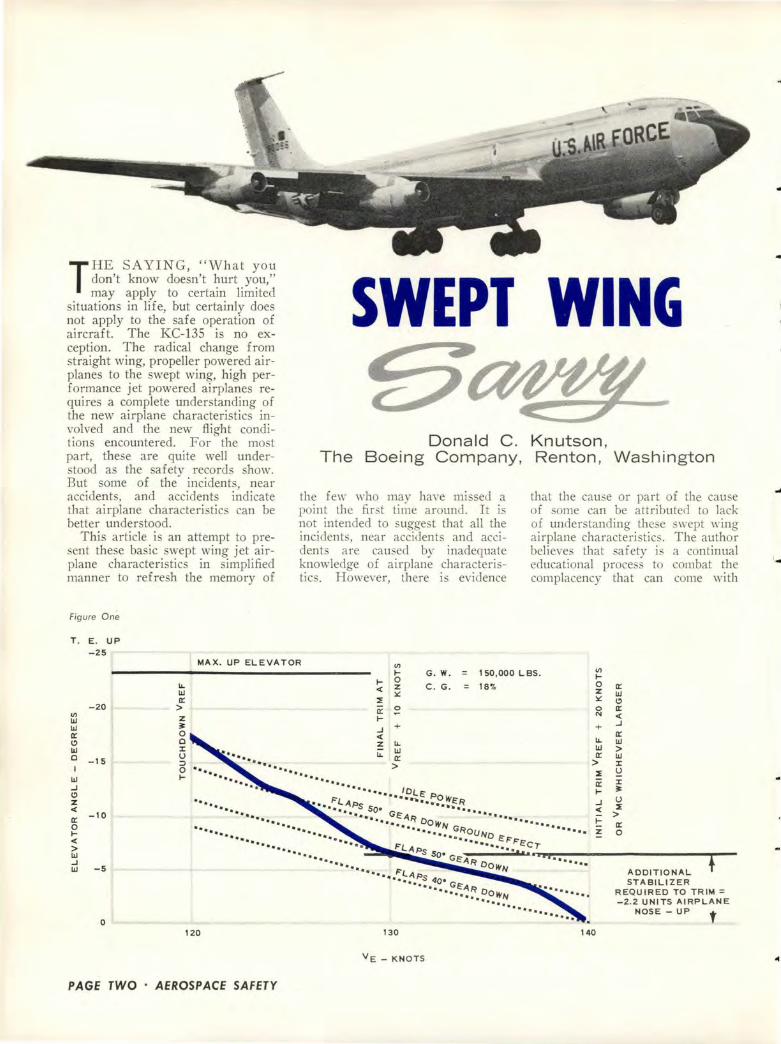
Figure One
T . E . UP
-25
SWEPT WING
Donald C . The Boeing Company,
the few who may have missed a point the first time around. It is not intended to suggest that all the incidents, near accidents and accidents are caused by inadequate knowledge of airplane cha racteristics. However, there is evidence
Knutson , Renton , Washington
that the cause or part of the cause of some can be attributed to lack of understanding these swept wing airplane characteristics. The author believes that safety is a continual educational process to combat the complacency that can come with
MAX. UP ELEVATOR V!
V! Ill Ill 0::: C)
Ill
-20
0 -15
Ill ..J C)
z <(
0::: -10 0 ~ <(
> Ill ..J Ill -5
0
ll.. Ill 0::: > z 3: 0 0 J: u :::1 0 ~
... ... ....... ... ······ ·······
~
~ 0 <( z
:.:: ~
~ 0::: ~
..J + <(
z ll..
ll.. Ill 0::: >
G. W. 150,000 L BS . V! ~
C. G. 18'1'. 0 0::: z Ill 11:: C)
0 0::: N <(
+ ..J
0::: ll.. Ill Ill > 0::: Ill
> J:
:1: ~ 0::: J:
3: • • • •• • I 0LE2 ••• F-tA •••• .._.POWER
.••• • •••••• ~Ps so• ····~~ •••• ~
..J u :1:
•••••••••••• •••••••• c:;AF=? DowN ··········· · ·~~ •••••• ••• ••••• • ••••• • •• • C:RouNo ••••• ••
........... •••••• FL•p •••••••• :~.F"cc..,. .. .•. .., s s ., ..... ~-------------•••• o• GE:A~ o ••••······· I ..... •• ,..,. OWN T
"••.. ~'"lA ADDITIONAL "•• •• Ps 40• STABILIZER
•••••• Gf!A.R "••····· DowN REQUIRED TO TRIM= "••······· -2. 2 UNITS AIRPLANE
NOSE- UP t
~ > ~ 0::: z 0
120 130 140
V E- K NO T S
PAGE TWO • AEROSPACE SAFETY
..
' ..
fa.mi.liarity with the airplane and mt swn.
How safe is the KC-135A airplane? Here is an airplane that first flew on August 31, 1956, and the fleet has acc,umulated over 800,000 hours and has achieved one of the best safety and reliability records in the Air Force. This record is the result of the Air Force's commendable training and operational effort as well as the afety and reliability designed into the airframe, systems and power plants. A gigantic step was taken by all parties involved when the move was made from the propeller type operation to the new high altitude, high speed, and high performance jet. The move was made with a minimum of incidents and accidents considering the large number of pilots involved, the large number of hour flown, the variety of weather and field conditions encountered, and the type of maximum performance missions being flown.
However, there have been some mishaps. Some can be attributed to not fully understanding one or more of the five new characteristics inherent in this type airplane which are not peculiar to the KC-135A alone, but are present in most similar swept wing, high performance, jet type aircraft. These are as follows:
1. M ova b 1 e stabilizer-elevator combination.
2. Turbo-Jet power. 3. Swept wing. 4. High speed capability. 5. The tuck or the change m
pitch stability at high Mach numbers.
These characteristics are basic with thi type of airplane design and should be as thoroughly understood by the pilots as the very ba ic characteristic that any airplane will stall if you bank too steeply while turning on final approach. Even this error is sti ll being committed !
MOVABLE STABILIZER-ELEVATOR COMBINATION
Lel' analyze these characteristic . For some pilots this may be the first time that they do not have all of the pitch control available by just moving the " tick." If a pilot has been in the habit of holding back pressure on the stick and not
z
~ ~ LL..
I Ill ;:;: ::::i (_)
MAX. T. 0. WT. 4 ENGS. T. 0. FLAPS GEAR UP
LL.. 0 u.J t<( a::
POWER POWER ON
KC-97 Vs
ON OR OFF KC-135A
~ I
Vs
! I
TRUE AIRSPEED- KNOTS
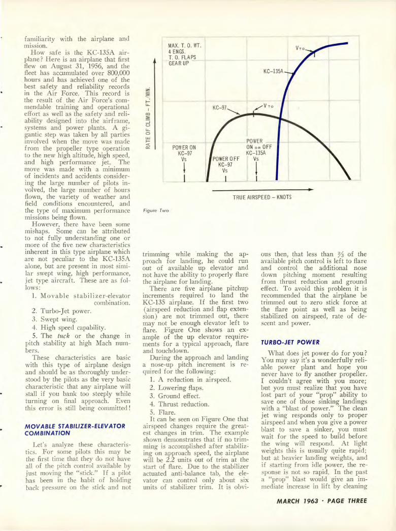
Figure Two
trimming while ·making the approach for landing, he could run out of available up elevator and not have the ability to properly flare the airplane for landing.
There are five airplane pitchup increments required to land the KC-135 airplane. If the first two (airspeed reduction and flap extension ) are not trimmed out, there may not be enough elevator left to flare. Figure One shows an example of the up elevator requirements for a typical approach, flare and touchdown.
During the approach and landing a no e-up pitch increment is required for the following:
1. A reduction in airspeed. 2. Lowering flaps. 3. Ground effect. 4. Thrust reduction. 5. Flare. It can be seen on Figure One that
airspeed changes require the greatest changes in trim. The example shown demonstrates that if no trimming is accomplished after stabilizing on approach speed, the airplane will be 2.2 units out of trim at the start of flare. Due to the stabilizer actuated anti-balance tab, the elevator can control only about six units of stabilizer trim. It is obvi-
ous then, that less than % of the available pitch control is left to flare and control the additional nose down pitching moment resulting from thrust reduction and ground effect. To avoid this problem it is recommended that the airplane be trimmed out to zero stick force at the flare point as well as being stabilized on airspeed, rate of descent and power.
TURBO-JET POWER
What doe jet power do for you? You may say it's a wonderfully reliable power plant and hope you never have to fly another propeller. I couldn't agree with you more; but yo!.! mu t realize that you have lost part of your "prop" ability to save one of those sinking landings with a "blast of power." The clean jet wing responds only to proper airspeed and when you give a power blast to save a sinker, you must wait for the speed to build before the wing will respond. At light weights thi is usually quite rapid; but at heavier landing weights, and if starting from idle power, the response i not so rapid. In the past a "prop" bla t would give an immediate increase in lift by cleaning
MARCH 1963 · PAGE THREE

RELATIVE WIND
Figure Three
up the wing with the increased airflow.
The "prop" effect also lowers the power-on stall speed. This gives you extra peed margin on takeoff where propeller takeoff speeds are calculated on power-off stall speeds to assure adequate margin of performance in the event of an engine failure. Therefore, with the "prop" you could pull the airplane off on takeoff, "hang it on the prop" and get away with it, as long as an engine didn't quit. However, the jet stall speeds are about the same, power on or off, (see Figure Two ) and the jet wing responds only to the proper airspeed on both takeoff and landing. So be sure the speed is correct for the weight on either takeoff or landing.
SWEPT WING
Now, how does a swept wing affect airplane characteri tics? First, it allow the airplane to go to a higher speed at altitude before the formation of shock waves on the wing causes the excessive increase in drag. Secondly, for equal dihedral angle any swept wing ha more roll from a given sideslip than a straight wing. Figure Three shows a comparison of a straight wing and a swept wing airplane and illu trates how the lift is affected by sideslip. Since the lift on a wing varies with the velocity vector perpendicular to the wing quarter chord line it can be seen from Figure Three, that for the same
PAGE FOUR · AEROSPACE SAFETY
* VELOCITY VECTOR PERPENDICULAR TO WING QUARTER CHORD LINE.
RELATIVE WIND
sideslip angle, the swept wing has a greater change in the total lift on each wing. The wing will roll faster for the arne sideslip angle.
It is important that asymmetric power conditions be corrected with the rudder for directional control with roll control applied only as necessary to hold the wings level. Excessive use of lateral control in place of rudder when controlling an engine failure on takeoff will give excessive spoiler drag and compromi se the three-engine take-
Figure Four
off and climbout capability. You may ask, "What is the cor
rect amount of rudder and aileron required to control an engine failure?" Proper rudder control means centering the needle and ball then holding the wings level with aileron. However, this requires ome up spoiler to counteract the rolling moment of the rudder. The easiest and recommended method i to simply use enough rudder o that the control wheel is centered. To center the wheel, use coordinated rud-
MACH NUMBER
1-...
60
50
g 40 0
w g 30 I-I-.J <(
20
10
0
. 74
420
GROSS
.78
I I I l
Joo . ~oo L a
440 460
.82 .86 .90 . 95
I I I I I I
" ' -~ ~
' ~--~
480
. ' '
500 520
T R U E A IRS P EED - KNOTS
' ' ' ' ' 540 560 sao
...

der in the direction the aileron control wheel i held. The ball will be slightly out of center and only rudder trim will be necessary. This avoids the more ensitive partial up spoile r· condition. It also provides the pilot with a simple and quick method of determining the correct control without referring to the turn and bank instrument which is not a primary reference under instrument conditions. The rudder should be applied and held steady, for a given speed and thrust, without "hunting" or "walking." No rudder should be used to turn; just bank with the control wheel.
Third, on landing approach a more nose-up body attitude is required for a sw~pt wing airplane. Previously the pilot's perspective was that of pointing the airplane's nose towards the touchdown point of the runway. Because of thi difference it is not always readily apparent that the actual flight path intersects with the ground at a point hort of where the airplane' nose is pointing. This characteristic can cause ome pilots to drop the nose and set up a dangerous rate of descent too do e to the ground. I would recommend that any time the rate of descent is as high as 1000 feet per minute during the last part of the approach, that proper consideration be given to being in trim, having adequate airspeed, and starting the flare early or to making a go-around. If the rate of descent is as high as 1200 feet per minute, go around I You can fly th is airplane more ski ll fully than that. Any pi lot who is too proud to go around when he has messed up an approach will be sorry some day.
HIGH SPEED CAPABILITY
How fast will this big heavy jet go? The answer is, too fast if you don't watch it, e pecially at low altitude. Here is a clean powerful airplane that can accelerate beyond its structural placard and limit in level flight. To exceed limits, all a pilot ha to do is to leave climb power on and level out at low altitude as directed by departure control. In the short time of about one minute ( depending on the starting speed) the airplane will quickly accelerate into the danger area even if at maximum gross weight.
In Figure Four the speed performance capability i hown at minimum and maximum gross weight with normal rated thrust on a tandard day. You can see that below about 22,500 feet altitude at maximum gro s weight the airplane can exceed the structural placard speed in level flight. Also, below about 16,000 feet altitude at any gross weight the airplane can exceed the recommended speed in level flight. Thi Figure also hows the structural clotted limit line up to which the airplane ha been successfully demonstrated during the Boeing structural integrity and fl utter flight test programs.
THE TUCK
One other characteristic of high speed fligh t with which the pilot should be familiar is the pitch down or "tuck" tendency which begins at approximately 0.86 Mach number. It is the result of a rearward shift in the center of lift on the wing, and to the reduction in downwash at the tail. This sudden shift is caused by the fo rmation of local
Figure Five
SUBSONI C
WI NG LIFT
shock waves over portions of the wing. The shift is rather rapid for a small change in Mach number and it is a little harder to maintain a trim setting when flying in this region. As can be seen from Figure Five, the shift in the center of lift is to the rear and this cau es the airplane to nose down with an increase in speed. This, of course, is the reverse effect from increasing airspeed at any lower speed where positive stabili ty exists. The airplane can be flown in the "tuck" region with elevator alone and with no trimming of the stabil izer, but it is always advisable to stay in trim at all times. The "tuck" characteristic should not be fo rgotten if turbulent air conditions are encountered at high altitude, uch as inadvertently entering the top of a thunderstorm.
In final analysis, it should be remembered that safe over<ltion of the KC-135 is really not different from that of other ai rplanes, if you know the airplane, understand its characteristics and follow normal safe piloting techn iques. *
NO RMA L DOWN WAS H
f'r~ .PRESSURE
~ ~
TRANSONIC
CENTER OF Ll FT MOVES AFT
~DISTRI BUTION STABILI ZER LI FT
WEIGHT
WING Ll FT
-I
WEIGHT
SHOCK WAVE
PRESSURE
DOWNWASH REDUCED AFT OF SHOCK WAVE
01 STRI BUTI ON --~-/ ELEVATOR
STABILIZER LIFT LI FT
MARCH 1963 · PAGE FIVE

PROBABLY THE OWLS who lived on the mountain and reputedly can see in the dark, and certainly the crew who just missed the mountain and
couldn't see very well in the dark got quite a scare out of this:
The aircraft entered the low level route during night VFR conditions. Entry was at proper altitude and airspeed. The flight continued along the route, making scheduled descents. After passing turning point number four the aircraft was established on heading and interval descents were made from 12,800 to 10,200, 9000 and 7500 feet. Suddenly, a third pilot, sitting in the IP position, noted a snowy mountain peak that covered three-fourths of the cockpit windshield directly ahead and yelled, "Pull up ! Pull up !" The pilot immediately pulled the aircraft into a steep climb, narrowly missing the peak. Post flight inspection of the radar scope film indicated that the aircraft was 20 miles north of course and was headed directly toward an 8340-foot mountain. It was also determined that the aircraft was approximately 20 miles off course on the last three legs of the route.
This is not an isolated case. "Black is Black," in the February issue, Aerospace Safety magazine, recounted three cases in which B-47s crashed during VFR, night, low level operations. Two of these were in known VFR conditions.
Here's another case, and, tragically, it has been duplicated. The pilot, while making a hooded night VFR VOR approach, mi interpreted the altimeter reading, descended below the minimum altitude and crashed hort of the runway. The safety pilot, flying in the front cockpit, allowed him elf to become distracted to the point that he failed to monitor the altimeter and allowed the aircraft to fly into the ground.
A few year ago, the crew of an Air Force transport, on a VFR night local flight, left closed traffic to avoid conflict with a jet recovery operation. Flight conditions were VFR, with a high overcast. The air-
PAGE SIX · AEROSPACE SAFETY
PHOTO: COURTESY WALT DISN EY PRODUCTIONS
craft proceeded toward uninhabited, rising, hilly terrain where there were no lights on the ground and struck trees. An emergency was declared and an immediate return to base attempted. The aircraft was damaged to the extent that power was lost on one ide. An inflight fire occurred and the aircraft crashed.
There have been many others.
* * * During taxi on an unlighted taxiway, the student,
under supervision of the in tructor, misjudged the distance to the edge of an intersecting runway and taxied into newly installed and unmarked curbing with resultant damage to the landing gear assembly.
* * * The landing was made after dark and, immediately
upon touchdown, the gear broke through crusted snow and the aircraft nosed over. Investigation disclosed that the field was closed, and so noted in the Airman's Guide.
* * * The pilot reported that he had been taxiing on an
unlighted taxi strip, using the aircraft nose wheel taxi light, when suddenly he saw the fence. He couldn't stop before hitting the fence.
* * * A night landing was attempted on a snow covered
runway that was unlighted except for threshold lights. The aircraft touched down long and on the extreme side of the runway. After a short roll the aircraft hit a snowdrift and the nose gear failed. The fact that the windshield was frosted over is considered contributory.
* * During the approach for a VFR night landing the
nose gear struck a powerline which caused the aircraft to crash.
* * * The pilot made an approach for a night landing on
a runway that was unlighted and covered by a light

snowfall. He aid the night was a bright moonlit one and he had no difficulty di tinguishing the runway until the last portion of the final approach. Difficulty at this time resul ted in touchdown on the extreme left side of the runway. The left wheel went off the edge, struck rough terrain and the aircraft no ed over.
* * * The night app roach was too low. The aircraft
st ruck treetops, a powerline and a television antenna on the roof of a hou e and crashed one-half mile hort of the field.
* * The approach was made at dusk in light snow and
rain and over a body of water, the surface of which was glassy. During a turn the aircraft descended and struck the water.
* * * During a night cross country the pilot initiated an
approach at a large municipal airport. During the right turn from downwind the aircraft struck the ground. The accident occurred during clear weather with 15 mile visibili ty. The pi lot stated later that he had erred in reading the altimeter.
RECOMMENDATIONS Since mis ion requirement a re such that niaht
fl ights be conducted , the obvious requirement is that precautions be taken to make uch flights as safe as possible.
Safety pilots in dual control ai rcraft must recognize their responsibility and take necessa ry action in suffi cient time to insure the safety of the flight.
Pilots must be repeatedly reminded of the dangers of complacencv and the feeling of well being that can occur at the end of a " routi ne" flight.
When at low level and doubt 'exists as to exact location. climb to a ,:afe alt itude.
Crew coordination must be especially emphasized during low level operations.
Dead reckoning must be a prima ry method of navi gation on short Jo,,· level flights and inflig-ht confl icts between DR and other na,·iaation method should be im mediately inve tigated .
Navigators must realize that any extended hadow behind a ridge on the radar scope indicates that the ai rcraft is below the ridge and po itive action must be taken.
The importance of out ide ob ervance during- VFR loK level flight deserve special emphasi . Cockpit lighting should be turn ed down a low as possible to aid in eeing outside the ai rcraft.
A ll crewmembers must be well aware of the afety hazards inherent in reading altimeters .
All checklist items possible hould be completed prior to entry in to a low level route to allow maximum time for attention to navigational instruments and outside scanning.
Vi ion, particularly near vision, deteriorates with age and cockpit activ ities require more time and light (or glasses) to correct this deficiency. One of the most difficult tasks is reading of fine pri nt, as on a facility chart, under red light. General health and the amount of recent rest also have considerable bearing on the abili ty to see nea1· objects.
Distant vision, if below par, a! o presents a hazard to the aircrewman. For example, an object such as an
aircraf t that can be seen at four mile with 20/ 20 vision would not be seen until two miles with 20/ 40 vision.
In flying, as in other hazard-a ociated activities, a basic safety concept i to recognize limitations, under-tand dangers of the particular ta k, then take every
precaution possible to minimize the hazards. This mode of operation is absolutely mandatory during low level, night flight. *
Robert H. Shannon, Safety Officer, Life Sciences Group
I N A R'ECENT F-1 OOD LANDING ACCIDENT, a rare but significant cond ition occurred that should be brought to the attention of all crash rescue personnel. The pilot was on
final approach when the engine failed . The aircraft landed short, skidded over the ground shedding ports and finally come to a stop in a semi-inverted position. While skidding, the left side of the fuselage was damaged and the left side o f the cockpit buckled inward displacing the left ejection seat trigger linkage sufficiently to cause the initi ator to fire . This immediately fired the seat catapult, but because of the partially inverted position of the fuselage, the ejection seat was held in an almost stowed position . The pilot's helmet and the upper left port ion of seat were dragged on the ground as the aircraft skidded in the semi -i nverted position.
Crash rescue units arr ived on the scene within 30 seconds, extinguished the fire and cut the seat and canopy initiator hoses prior to rescue attempt. When the seat initiator hose was cut, a loud repor t was heard indicating there was pressure in the hose. The significance of this was not recognized by crash personnel because both ejection handles were in the stowed position and the canopy frame was still on the a ircraft in its normal pos ition .
In order to remove the pilot, fire fighters raised the nose of the aircraft to gain access. The fact tha t every sequence necessary for ejection had already token place was unknown to the rescue personnel.
As the forward section of the fuselage was lifted and rotated, the highly compressed gas that hod been generated and retained in the catapult column when the charge fired was released. The seat and pilot were forced out of the cockpit approxi mately three feet. Two firemen were struck by the seat, one of whom sustained a bruised right knee, the other a fractured right kneecap, right shin and right forearm lacerations.
Pathological a na lysis disclosed tha t the pilot was dead prior to ejection of the seat. Because of the design of the system, once the catapult charge has fired , the high pressure gas will remain in the catap ult column unless the seat is fully launched . Cutting the initiator will not reli eve the pressure in the catapult column.
It has been recommended that AFLC initiate corrective action for this condit ion and that crash rescue personnel be mode cognizant of this hazard. *
MARCH 1963 · PAGE SEVEN

L ATE IN 1962 a C-47 crash landed and a DC-7 ditched after each had experienced a runaway prop. These are but two more occurrences in a sizeable
li st of spectacular aircraft accidents that have stemmed from this problem. They are also indicative that, although refinements such as pitch locks, mechanical low pitch stops and negative torque control devices have been developed and installed, the problem still exists. Indications are that, so long as we operate aircraft with propellers, knowledge of what action to take when a propeller malfunctions is mandatory. Admittedly, true runaways are rare. But so are inflight fires and structural failures. In such cases it is the eriousness of the emergency that makes prompt, knowledgeable action so important.
Let's break this malfunction clown, identify it in its various forms and consider action to be taken.
One of the first clues that a propeller has exceeded allowable RPM limits is sound. If an out-of-sync beat develops at maximum power on takeoff, abort! Something is wrong. Get the airplane stopped and check it out.
If airborne, or too late to abort, first attempt to bring RPM within limits by moving the prop control toward decrease RPM. (It is not uncommon for RPM to surge if power application has been rapid. Also, the governor control could be out of adjustment.) If this has no effect, partial reduction of power may. Provided airspeed is held constant or reduced to minimum safe limits, power reduction will be the most effective method of reducing RPM when prop control is ineffective. Feather the propeller as soon as terrain clearance permits afe flight without power from the engine concerned. If the propeller will not feather, fly the aircraft at minimum safe speed and use power on the engine up to maximum continuous RPM. Land on the nearest suitable runway.
In crui e, RPM fluctuations can occur from sudden power changes applied to the engine or air loads applied to the propeller. For example, should an engine stop firing because of fuel starvation and then fuel be resupplied, an overspeed and possibly a runaway will result. The same potential exists when a propeller is feathered, then unfeathered without the precaution of selecting high pitch and a low air peed. Pitch hunting can tern from poor fuel vaporization if cylinder head temperatures are allowed to drop well below normal limits, a on letdown or during flight at reduced peed through heavy rain. Pitch hunting may also occur at high altitude if boost pumps are not turned on to supply continuous
Major T. J. Slaybaugh
pressure to the ca rbu rctors. Minor RPM fluctuations from causes uch as the e po e no great threat and can be avoided or promptly corrected by the aircrew.
Overspeed can occur at altitude if large power advances are made rapidly, particularly if airloads are also changed as would be the case during stall practice. Again, RPM change from such causes can normally be either avoided or controlled by the aircrew.
There is no mistaking the true runaway when it occurs at normal cruise airspeed. There is no other sound quite like it. The high-pitched, penetrating whine will easily make itself heard throughout the best insulated flight decks. A check of the tachometers will disclose which prop is running away. If the malfunction occur suddenly, as is usually the case, the RPM will increase from cruise setting to the vicinity of 4000 RPM or more almost instantaneously. The procedure in this case has been generalized by a field service representative of one propeller manufacturer as: "Pull everything back but the feathering button-throttle, RPM, yoke, mixture on the bad engine-the works." Feather immediately. If the propeller does not feather, reduction of true airspeed is the single action that will have most effect on reducing RPM of an uncontrollable propeller. Once the aircraft has been slowed to minimum safe flight speed feathering action may be effective. It may have been that aerodynamic loads on the prop at high RPM were too great for the feathering motor to overcome.
::E a: a: w
a: w .J .J w a. 0 a: a. ...... VI 0 z ::;)
0 a. ~ (!)
< a: 0
WINDMILLING DRAG AND E . R . P . M. VS AIRSP EED
6000
5000
4000
3000
2000
1000
0
6000
5000
4000
3000
2000
1000
0
DC-68, CV-440 R2800 G. R. = . 45
AIRPLANE ENGINE PROPELLER CONDITION
43E60 6895A-8 DIAM = 13. 5' ALTITUDES . L.
30°
---BRAKED ENGINE ----COUPLED ENGINE
, 30°
I I
/ / 30"
/ /
/ ~
0 100 200 300
INDICATED AIR SPEED, M. P. H.
400
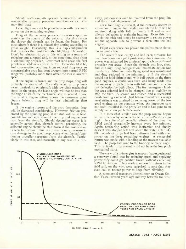
Should feathering attempts not be succe ful an uncontrollable runaway propeller condition exists. You may find that:
Level flight may not be po ible even with maximum power on the remaining engines.
Drag of the runaway propeller increases approximately as the square of the velocity. For this reason the slower the aircraft can be flown, the better. For most aircraft there is a takeoff flap setting according to gross weight. Es entially, this is a flap configuration that provides the most favorable lift/ drag relationship. Don't be reluctant to go to this setting as a means of reducing true airspeed and, at the same time, drag from a windmilling propeller. Over most land area the fuel problem is seldom a critical factor. Even should it be, fuel con ervation resulting from reduced drag once an uncontrollable prop has been brought into normal RPM range will probably more than offset the loss in aircraft speed.
If the engine is frozen and the prop stops, drag will probably be increased. ormally when a prop runs away, particularly on aircraft with low pitch mechanical stops on the props, the blade angle will not be less than the angle at which the mechanical stop is located. Since thi is at a degree setting above the crossover point ( figure below), drag will be less windmilling than frozen.
If the engine freezes and the prop decouples, drag will be decreased considerably. However, friction generated by the spinning prop shaft stub will cause heat, possible fire and separation of the prop and engine nose case from the aircraft. Should decoupling occur it i generally agreed that, aircraft control permitting, the adjacent engine hould be shut clown if the no e section is seen to discolor. This is a precautionary measure in case damage to the good prop occurs when the malfunctioning propeller separates from the aircraft. Particularly in this case, and normally in any case of a run-
ILL
C1
ISO
<J) 100
~
LL
<J a: 0
50
WINDMILLING DRAG ESTIMATE FOR R-4360 ENGINE AND 16. 5 FT . PROPELLER, A . F . 452
away, passengers should be removed from the prop line and the aircraft depre surized.
On a four engine aircraft, if the runaway occurs on an outboard engine fu ll rudder and ai leron trim will be required along with full or nearly fu ll rudder and aileron deflection to maintain heading. Even this may not do the trick and it may be necessary to reduce power on .the opposite side to prevent a turn into the bad engme.
Flight experience has proven the point made above. To recount a few:
The aircraft was empty and had been airborne for over two hours on a pilot proficiency check mission. As power was advanced for a missed approach an outboard propeller ran away. Since the aircraft was low, slow, and in a high drag configuration, immediate action was mandatory. Minimum safe flying speed wa maintained and drag reduced to the minimum. Still the aircraft would not hold alti tude and, with full power on the three good engines, a continuous turn was being made into the runaway propeller, even with full trim and full control deflection by both pilots. The first emergency landing area selected had to be changed due to inability to stop the turn. A second was chosen and a successful crash landing executed. Just before touchdown a wing level attitude was attained by reducing power of the two good engines on the opposite wing. An improper part had been installed in the propell er and it had gone to an aerodynamic low pitch blade angle.
In a somewhat similar case the prop control began to malfunction by increments on a trans-Pacific cargo flight. In spite of all remedial efforts of the crew the RPM would sporadically increa e every few minutes. Again feathering action was ineffective and finally descent was stopped 500 feet above the water after 24,-000 pounds of cargo had been jettisoned and with max power on the three remaining engines. A successful return was made with a landing at the nearest avai lable field . The prop had gone to the five-degree blade angle. This particular prop assembly did not have the low pitch mechanical stops.
The crew of a twin engine transport that experienced a runaway found that by reducing speed and applying power they could get positive thrust without exceeding RPM limitations. They made a successful return to the field and, on the way, were surprised to note that they even had to reduce power to keep from climbing.
A commercial' transport ditched near an Ocean Station Vessel several years aero midway between the west
l!)
< a: 0 -- FROZEN PROPELLER DRAG
--- /BASED ON C- 97 WIND TUNNEL --- TESTS AND CALCULATIONS __
..... _____ _ 0
~--------------------------------------------------------------------0 10 20 30 40 50 60 70 80 90
BLADE ANGLE -- o B
MARCH 1963 · PAGE NINE
coa t and Hawaii. A controlled ditching was decided upon by the pilot after he had experienced a runaway propeller.
In some cases loss of the propeller may occur, even though the crew attempt to prevent this. In one case in which this happened, control to the adjacent engine were cut and a 20-foot slice torn in the fuselage when the propeller left the aircraft. Fuselage damage included cutting of several control cables. The crew, using power and controls remaining, made a semi-controlled night ditching.
If fire occurs, or vibrations increase to the point that structural damage is feared, intentional freezing is probably the more recommended of two bad choices. In one case, wherein vibrations became extremely severe, intentional freezing was initiated by oil tarvation and when the bearings froze the prop separated and embedded itself in the fuselage. The adjacent prop had been feathered during the freezing process. After the prop came off, this engine was restarted and a successful three-engine flight made to a suitable field. A le on learned in thi case wa that severe vibrations had made the gyro stabilized compas system unreliable and the aircraft had reversed course. This the crew discovered when they broke out of clouds and noticed the moon to be on the opposite side.
WHEN A PROP RUNS AWAY
In yet another case a runaway propeller was frozen and when the prop came off it damaged the adjacent propeller to the extent that two engines were then useless. Far at sea, with fuel now a critical problem due to the high power settings required on the two remaining engines and the drag of the damaged nacelle on the opposite wing, the crew found it necessary to descend clo e to the surface and take advantage of ground affect. At approximately 100 feet it wa found that power could be reduced and airspeed maintained. With reduced fuel flows obtained as a result of thi power reduction, and near superhuman effort in controlling their out-of-trim transport, the 10-man crew flew six hour to a safe landing at Hilo.
Normally, if freezing is decided upon, the thinking is that pulling the oil shutoff valve out and leaving it out until the engine freezes is preferable to intermittent shutting off of the oil. This recommendation is based on the possibility of intermittent friction heating followed by lubrication re ulting in gradual washing away of the bearings until tolerances are o great that freezing cannot be effected. In at least one installation, reportedly due to the weight of the prop and therefore the expectation that it would separate if stopped suddenly, intermittent freezing i preferable. For specific aircraft consult the Dash One.
To recap, first attempt to bring the RPM down to the desired setting by use of the RPM control. If this is ineffective, reduce power and air peed, terrain permitting. If the high RPM limit is being exceeded at part throttle and minimum safe flight peed, try intermittent feathering a long as some power i needed from this
PAGE TEN · AEROSPACE SAFETY
Following an aircraft ditching, power requirements to offset propeller drag were computed as:
Uncoupled 275 BH P
Windmilling 1060 BHP
Frozen 1380 BHP
engine to sustain flight. Feathering, if effective, is an emergency means of increasing prop pitch in this case. A RPM drops within limits, unfeather. Repeat as necessary. As soon as adequate terrain clearance can be maintained on the remaining engines, feather.
In case of a runaway propeller that will not feather: • Slow the aircraft to minimum safe flight speed. • Fly at a low altitude where increased air density
reduces true airspeed. Don't freeze the engine unles you fear tructural
failure from vibration or fire. Chances are the drag will be increa eel and, if the propeller uecouples, sub equent separation and po sible fire and structural damage will result. If the decision is made to freeze, consider shutting clown the adjacent engine during the proce s and keep trying to feather as the RPM decreases. As the RPM decrease the feathering motor may be able to overcome the centrifugal turning moment acting on the blade .
To fly slower you may be able to: jettison fuel and cargo and extend flaps to takeoff setting.
Notice the RPM. If RPM is below max allowable at minimum safe flight speed the propeller will probably be again t the low pitch stop. If thi i the ca e, ad\'ance power to not exceed maximum continuou allowable RPM. This will result in a decrease in drag and, at low true airspeeds, a positive thrust condition will likely result.
Land at the nearest suitable field. Tf you have re-olved this emergency and have a flyable aircraft don't
expose yourself to the possibility of compounding uch a erious emergency by flight any longer than absolutely necessary.
One more point: The information presented in this article is of general nature. This it must be if the principles are to apply to all propeller driven aircraft. In orne cases procedure may differ for specific aircraft.
Should uch conflict exist, Da h One procedures mu t always be followed. It would be well to reiterate that completely uncontrollable, high speed runaways are comparatively rare. Admittedly, modifications in recent year have reduced the frequency of thi emergency, or at lea t minimized it by limiting propeller blade angle to approximate low pitch po itions in most case . Still, as noted in the opening sentence, runaway propeller induced accidents still occur. It i conceivable that the high pitched scream of a runaway, the near-uncontrollability and the fear that a prop might lice through the fuselage or tear an adjacent engine loose is conducive to panic, particularly during instrument or night conditions. Knowledge of what i happening, what can be done, and the proper sequence of corrective steps will allow the crew to most successfully cope with this, or any other emergency. *

LIGHTNING PROTECTION E. R. Roth , Missile Safety Division
Lightning, the spark to end all sparks, is more than an interesting weather phenomenon;
it is a potential hazard to contend with in the missile business. Some of our operational
missile systems including the Atlas, Titan, Jupiter and Mace have experienced lightning
damage. The brief description below might explain why and how lightning can affect missile
system circuitry and components.
THE FAMILIAR THUNDERCLOUD is nature's warning of the possibility of a lightning strike. In its formation, the storm cloud builds up a tremen
dou electric charge differential between cloud and earth ot· between cloud and cloud. The way this occurs is not clearly understood, but it is suspected that the negative charges in the lower layer of the storm cloud result from frictional reaction between air currents and rain droplets. The charge buildup imposes an increasing difference of electric potential until, eventually, the dielectric strength of the in ulating air is broken down and the static potential is discharged through the resulting lightning.
The difference of electric potential between the cloud and ground may be measured in millions of volts, and the discharging current may reach values of tens of thousands of amperes within a few millionths of a second. Accompanying the discharge current is a rapidly expanding electromagnetic field which collapses at the completion of the lightning. This changing electromagnetic field is sufficient to induce several thousands of amperes of electric current in conductors in the proximity of the lightning occurrence. Also accompanying the lightning strike are electric currents within the earth itself. Very little is known regarding the nature of these earth currents.
MARCH 1963 • PAGE ELEVEN

lightning protection
cont i nued
A single, typical lightning strike may represent 40 billion watts of electric power. This amount of po~er represents nearly one-fourth of _th~ total po~er capac1ty of all the electric generators w1thm t~e Umte~ State . More vividly, the energy released dunng the_ tunespan of a lightning occurrence can equal that ~h1ch wou~d be required to lift Hoover Dam approximately s1x inches.
The purpose of lightning protection is to safeguard personnel and system coml?onents by provi~ing a path of low resistance for the dtscharge of electncal current caused by storms.
Inadequate protection system will allow induced and direct current flows of a large magnitude to pervade missile systems circuits. This can. cause th~ failure of electronic components and result m extens1ve damage and missile down time. For example:
• At an Atlas D site two lightning strikes damaged amplifiers, fuses, diodes, power transistors and relay coils at different complexes.
• A tactical missile wing reported that lightning struck on or near one launch pad then jumped to two adjoining pads. Hydraulic and temperature control hoses separated from the missiles. Investigation revealed that explosive squibs in the hoses had detonated. Lightning protection, not installed at the time of the incident, is currently installed.
• Titan sites have experienced lightning damage on two occasions. In both cases the strike current traveled along exposed cable at ground level before it entered the complex. Action is being taken to shield, bury ~nd ground this cable to prevent recurrence. The followmg components were damaged: 200 and 400 amp fuses, mercury vapor lights , an RF test set, eight guidance panels, a 35.5 KV A transformer, TV camera and monitor.
• During te t operations at Cape Canaveral a Minuteman complex suffered some damage during a heavy
PAGE TWELVE · AEROSPACE SAFETY
thunderstorm. It was apparent that the lightning entered the launch area equipment through the AC power system. Switches, relays, current monitors, various ~anel s in the control racks, diodes, relays, filters and restston; were damaged.
A good lightning protectic;m syste~n will p~·even_t or minimize the damage from d1rect stnkes of hghtmng; it will assure that the lightning finds a safe. path to ground. Air terminals (metal rods topped w_1th_ noncorrosive metal caps) are placed on top of a b1.11ldmg or around the building. The top of the terminals should be at least one and one-half to three times as high as the building they protect. The bases of ~he mast_s should be secured in concrete and the groundmg termmal connections and girdle components welded to the bottom of each ma t. The ground terminal may be a copper plate surrounded by charcoal and buried in the ground below the water level. The connecting girdle consists of copper cable which encircles the building and insure effective grounding and uniform potential. These conductors connect the air terminals with each other and with the ground terminals. All metal or electri~al c::quipment within the building should be copper w1re mterconnected, with a single connection to the gr~unding girdle. This insures a minimum of ground loop mduced voltage (by maintaining a uniforn: potential)_ and pr~vides a very satisfactory groundmg of static electnc charges as they accumulate. Details for different configurations of lightning protection systems can be found in TO 31-10-24.
The resistance of the lightning protection system should not exceed 10 ohms. To obtain continuou and reliable protection, the system should be maintained so it will function efficiently. If any of the parts of the sy tem are corroded, broken or poorly installed, the resistance of the system could increase immeasurably. Under these conditions, the electrical current from the lightning discharge could take a more favorable path through the building or its contents causing fires, burning out components or initiating explosive devices.
During periodic in pections particular attention should be given to conductors which enter the ground, since experience shows that deterioration is most active at these locations. Testing consists of placing one lead of the test equipment, an ohmmeter, to a known ground (a ground rod sufficiently sunk into the ground to insure good contact with permanently moist earth) and a second lead to each of the air terminals in turn. The metallic urface forming each electrical contact should be

carefully scraped to remove any paint or oxide film . The provisions of AFM 32-6 and TO 31-10-24 concerning the inspection and maintenance of installed lightning protection system should be u eel as guidance.
Personnel hazards created by lightning trikes on or near a missile system could be any of the following or combinations thereof:
• E lectric shock ranging in magnitude from mild to fatal.
• I nju ries from pyrotechnic device exploded by the strike or induced currents.
• Injuries from flying objects from buildings, towers, etc., hit by the str ike.
Some suggetions for personnel behavior just pri r to a storm and during a storm are as follows:
Approach of Storm: • Suspend work involving hazardous materials such
a pyrotechnic , flammable liquid and gases. • In building where lightnino· protection is avail
able, it is unnecessary to evacuate the bui lding; however, operations hould be discontinued. A potentially explosive process, such a a propellant load ing, should not be started if a storm is pending.
During a Storm: • If outside and a choice of a metal building or a
wood building is offered, choose the metal building. • If inside a building equipped with lightning pro
tection, remain there. • If inside a building, keep away from metal ob
jects. • If it is necessary to remain outside during a thun
derstorm, stay away from isolated small helters, isolated trees, wire fences and wide open paces. Seek shelter in a cave, a depression in the ground, deep valley or canyon, the foot of a steep or overhanging cliff, within den e woods or a grove of tree , provided one does not stand directly against or beneath large trees.
E lectrical torm warning devices were in tallecl at Patrick Air Force Base to provide warning of pos ible lightning strikes for Cape activities. Thi permits the breaking off of any hazarclou operations (for example, fuel loadings ), moving of fuel supplies to afe locations, checking the grounding system and leaving the danger area. If proven effective, the lightning alert system might also be installed at missile sites throughout the country.
In addition to the personnel haza rds which accom-
MISSILE
SAFETY
DIVISION
pany a lightning strike, the missile system itself (see examples above) can suffer substantial component damage as a result of the di rect, induced or branch currents generated by the trike. As mentioned above, past damage has involved the firing of squibs, shorted diodes, blown fuses, and horted amplifiers, all of which required trouble shooting and replacement.
This type of lio-htning damage is difficult to eliminate, but it can be reduced to a minimum by providing a good grounding circuit for the various facilities and by connecting the missile components to a common ground point. All ground connection should be connected in as straight a line as possible in order to minimize the magnitude of earth currents induced by the lightning trike in metallic structures and electrical ci rcuits.
The Mi sile Safety Division of the Directorate of Aerospace Safety, U AF, evaluated the existing lightning protection sy tem for surface launched missiles. Re ul ts were published in a technical afety review No. 14-62. The review pointed out that missile damage to date was caused by induced or branch currents generated by the direct strike either during or after it contacted the surface of the earth. Several recommendation were made to improve the grounding of missile systems. The review concluded that damage to missile systems cannot be entirely eliminated, but specialized research in such areas as induction effects and earth current, protective devices, and site grounding will provide information needed to reduce lightning damage. An Air Force contract with the General Electric Company has since been negotiated by AF Systems Command to answer some of these questions. In the meantime, concerned personnel must in ure that their grounding sy tems are in o-ood condition and that all components which can be a s~uce of connection to the complex are also adequately grounded. Remember, lightning seeks a good ground. If on t~e othe~ han~, good grounds are not provided, the lightnmg. st:1ke. w1l~ find another path through or adjacent to m1 sile CircUitry, and when thi happens we can ex-pect lightning damage. '
References: AFM 32-6 - Explo ive Safety Manual Section
0616, Requirement for Lightning Protection. ' . T<? 31-10-24, f~rmerly TO 31-1-79 - Theory,
PnnCiple and Practices of Grounding Procedures and Lightning Protection for C-E Equipment Facilitie and Systems.
AFIM study o. 14-62, Lightning Protection for Surface Launched Missiles, 25 Jan 1961. *
MARCH 1963 • PAGE THIRTEEN
ZERO SECOND __ NYARD
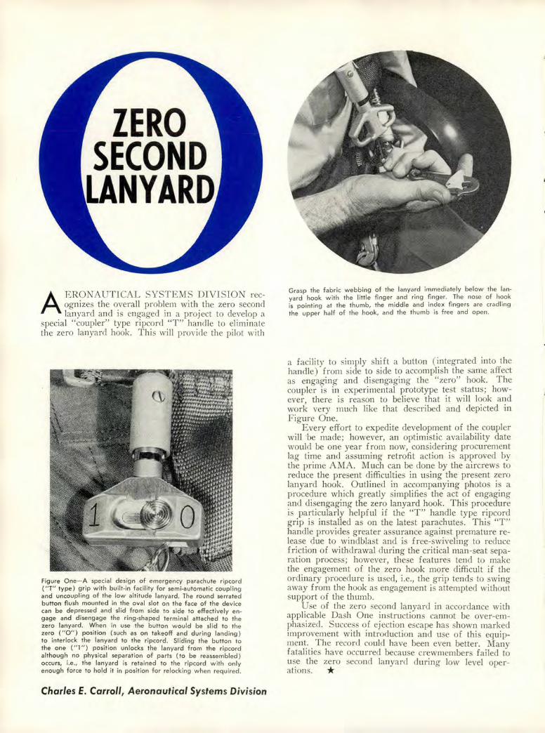
AERONAUTICAL SYSTEMS DIVISION recognizes the overall problem with the zero seconcl lanyard and is engaged in a project to develop a
special "coupler" type ripcord "T" hand le to eliminate the zero lanya rd hook. This will provide the pilot with
Fig ure One-A special desig n of emergency parachute ripcord ("T" type) grip with built-in facility for semi-automatic coupling and uncoupling of the low altitude lanyard. The round serrated button fl ush mounted in the oval slot on the face of the device can be depressed and slid from side to side to effect ive ly engage and d isengage the ring-shaped terminal attached to the ze ro la nyard . When in use the button would be slid to the zero ( " 0 ") position (such ·as on takeoff and during landing) to inte rlock t he lanyard to the ripcord . Slid ing the button to the one ("I") pos ition un locks the lanyard from the ripcord although no physical separation of parts (to be reassembled) occurs, i.e., the lanya rd is retained to the ripcord with only enough force to hold it in position for relocking when required.
Charles E. Carroll, Aeronautical Systems Division
Grasp the fabr ic webbing of the lanyard immediately below the lanyard hook with the little finge r and ring finger. The nose of hook is pointing at the thumb, the middle and inde x fingers are cradling the upper half of the hook, and the thumb is free and open.
a facility to simply shift a button (integrated into the handle) from side to side to accomplish the same affect as engaging and disengaging the "zero" hook. The coupler is in experimental prototype test status; however there is reason to believe that ·it will look and work very much like that described and depicted in Figure One.
Every effort to expedite development of the coupler will be made; however, an optimistic availability date would be one year from now, conside ring procurement lag time and assuming retrofit action is approved by the prime AMA. Much can be done by the aircrews to reduce the present difficulties in using the present zero lanyard hook. Outlined in accompanying photos is a procedure which greatly simplifies the act of engaging and disengaging the zero lanyard hook. This procedure is particularly helpful if the "T" handle type ripcord grip is installed as on the latest parachutes. This "T" handle provides greater assurance against premature release due to windblast and is free-swiveling to reduce friction of withdrawal during the critical man-seat separation process; however, these features tend to make the engagement of the zero hook more difficult if the ordinary procedure is used, i.e., the grip tends to wing away from the hook as engagement is attempted without support of the thumb.
Use of the zero second lanyard in accordance with applicable Dash One instructions cannot be over-emphasized. Success of ejection escape has shown marked improvement with introduction and use of this equipment_. . The record could have been even better. Many fatalrtJes have occurred because crewmembers fai led to use the zero second lanyard during low level operations. *
•
•
•
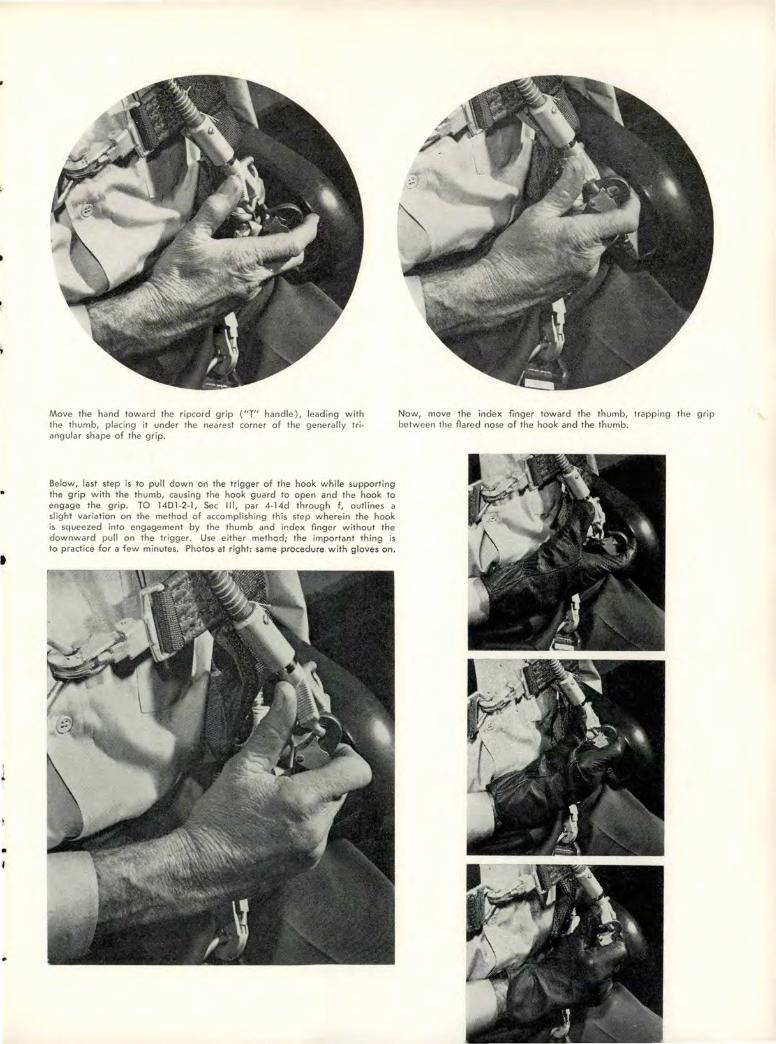
Move the hand toward the ripco rd grip ( " T" handle), leading with the thumb, placing it under the nearest corner of the generally triangular shape of the grip.
Below, last step is to pull down on the trigger of the hook while supporting the grip with the thumb, causing the hook guard to open and the hook to engage the grip. TO 1401-2-1, Sec Ill, par 4-14d through f, outlines a slight variation on the method of accomplishing this step wherein the hook is squeezed into engagement by the thumb and index finger without the downward pull on the trigger. Use either method; the important thing is to practice for a few minutes_ Photos at right: same procedure with gloves on .
Now, move the index finger toward the thumb, trapping the grip between the flared nose of the hook and the thumb.

n
••• from REX RILEY
T-BIRD TRASH- Take a look at the photo hawing llashlights, wrenches, screwdrivers, etc. All these items came from ix T-33s that were flown to an overseas TCTO facility. Is it any wonder we have foreign object damage, binding or stuck controls, etc ? This doe n't look so good for pilots or maintenance people. If you lose something in the cockpit while flying and can't find it after landing, write it up in the 781.
\_
SMART THI KING A D A CAUTIO NOTEShortly after takeoff an F-102 pilot found his cockpit full of smoke. An area under the left armrest seemed to be the source. The pilot declared an emergency and prepared to land right quick but when the gear was lowered, the nose gear showed an unsafe condition. Even afte r he used the emergency gear system, the pilot still had a nose gear unlocked indication. A chase pilot at first reported all gear appeared to be down and locked, but a few minutes later saw the nose gear retract about halfway. Under the direction of the Flyi ng Safety Officer and a Convair tech rep, the pilot recycled the gear several times using both the normal and emergency systems. Eventually all three gear retracted which told
PAGE SIXTEEN · AEROSPACE SAFETY
them that electrical power was continuou to the "gear up" solenoid . The pilot was then told to turn the master switch to "trip," then "off." When the master switch was turned off, the gear dropped down and locked . An uneventful landing was made. Good job for everybody. One slight hitch developed though: As the '102 stopped, the pilot turned the master switch "on" to advi e the tower he was in good shape. As the switch hi t "on" the nose gear retracted an I the main gear unlocked . The unit is recommending the above procedure be added to the Dash One, except they caution not to turn the rna ter switch back on .
WORRIE D-about whether or not both tiptank (T-33, that is) will jettison if you should have to punch them off? Records how that les than two per cent of tip tank j etti ons have been unsucce ful. There were at least six major accident last year involving T -33s with a heavy fuel configuration. In one accident the pilot stated he didn't punch the tips off for fear only one would go. So, if you find yourself in a bind and the tiptanks would be better off than on, have at itwith confidence!
SAY AGAIN-Instructor pilot had better speak clearly and distinctly. And, pilots and student pilots, give a look at what you're pulling, pushi ng, actuating, etc. The following is an account of a T -38A incident that occurred when a tudent pilot misconstrued wo rds from
•
•
•
•
I
' A
•
his instructor pilot in the rear seat: After 15 minutes in the local area, the aircraft re
turned to the traffic pattern, and two closed circuit were made. On the pullup for the third go-around, the ·tudent was told by the lP that the pattern would be left
engine-out, simulateJ single engine pattern . Then he was reminded to stow fully the gear alternate release T handle after actuation. As the aircraft progressed on the downwind, the instructor told him he'd better get to that lanyard. Instead, he reached over and pulled the canopy jettison T -handle. Canopy separation was clean and didn' t strike any part of the aircraft. The windscreen provided protection so the windblast in the front cockpit was mild, although some dust was blown into the student's eyes. His visor was down. The IP experienced nothing more serious than very slight airflow around the shoulders and neck. Interphone communication was ruffled because of the noise, however, the IP took the controls and landed the aircraft all right.
T-33 ABORT- "During a demonstration instrument takeoff the Instructor Pilot became confused as to his position on the runway and aborted takeoff when the aircraft was accelerating normally."
This was listed as the primary cause of a major accident. But the contributing causes and recommendations are the ones that we should read and heed. Take a look:
Contributing Cause: Pilot factor in that the pilot inadvertently extended the speed brakes when the throttle was stopcocked, thus greatly reducing the possibility of a successful barrier engagement. Second, he did not follow correct abort procedures in that he did not raise the wing flaps or open the canopy to decrease the stopping distance. Third, he used poor braking technique by locking the brakes, sliding the tires and, therefore, decreasing optimum braking effici'ency.
It is recommended that T -33 pilots be briefed on the following:
• Inherent hazards involved when the Instructor Pilot has his attention divided during ITO demonstrations.
• The possibility of extending the two-position speed brake switch when the throttle is s·topcocked in an emergency.
• The importance of following correct abort procedures to insure a successful abort and subsequent barrier engagement, should i>t become necessary.
• That maximum braking efficiency is lost when the brakes are locked during emergency braking.
A~E YOu SURE
YOU'Rto T He I. p. ?
GOOD GUY- his name is Roger W. Mead, Jr., A2C, Det 5, 35 Weather Sq, Paine Field, Washington. Airman Mead is a weather observer and was on duty at the observation sta tion at the north end ·of the field when he noticed a small civil plane ( no lights on) land on runway 16. In stead o£ just s itting on his duff like a lot of us would, he called the tower real quick. And a good thing too. A C-130 had just been cleared to take off on Run- ~ way 34. Airman Mead 1' ~' '" ·:: ~ probably saved some lives )l - -and a couple of airplanes by E~ _ • -=--noticing, thinking and do- : _ ~"S: ing. It's nice to have him -- - =--' ,_-.-- ,:~ around. /1..5-
SURPRISE- Certain statements in AFR 55-42 dated 4 Jan 1962 caught a lot of troops by surprise. Major Terry Lee, Flying Safety Officer at Norton AFB, brought it to our attention. The reg, in part, states: "All jet trainer and fighter aircraft ... will land and take off toward an available arresting system during normal operations;" also, "that the pilot assumes responsibility for requesting that the barrier is raised/ lowered," and, "that each pilot, prior to takeoff, makes his barrier position request before he changes from tower control to departure frequency."
BY GEOR.GE, I 'VE ALwAYS
WUNDERED, T ERRY ..
WHAT HAPPE'NED TO
DUAL QUALIFIED PILOTS- Flight Safety Surveys often reveal a deficiency in one particular area: unit aircrews flying ~ot~ the UE and T-33 aircraft generally demonstrated limtted knowledge about the T-Bird. The average scores obtained by these dual qualified pilots on relatively simple T-33 emergency procedure quizzes were certainly not comforting to the fly-safe officers.
I_n addi~ion to poor grades on the quizzes, these dual quahfied ptlot often gave little consideration to T -33 currency. They generally retained regulation currency but are "dangerously proficient." '
Commanders and Ops officers can hardly justify letting pilots fly both UE and T -33 aircraft when records show infrequent T -33 flights, practically no night flying, and very little instrument or hooded time-especially when the quiz grades show that these pilots are not so hotsy-totsy on their emergency procedures.
Mr. Ops Officer, you might save your commander embarrassment more than somewhat if you look into the T-Bird qualifications of your dual qualified pilots.
MARCH 1963 · PAGE SEVENTEEN
RIDE
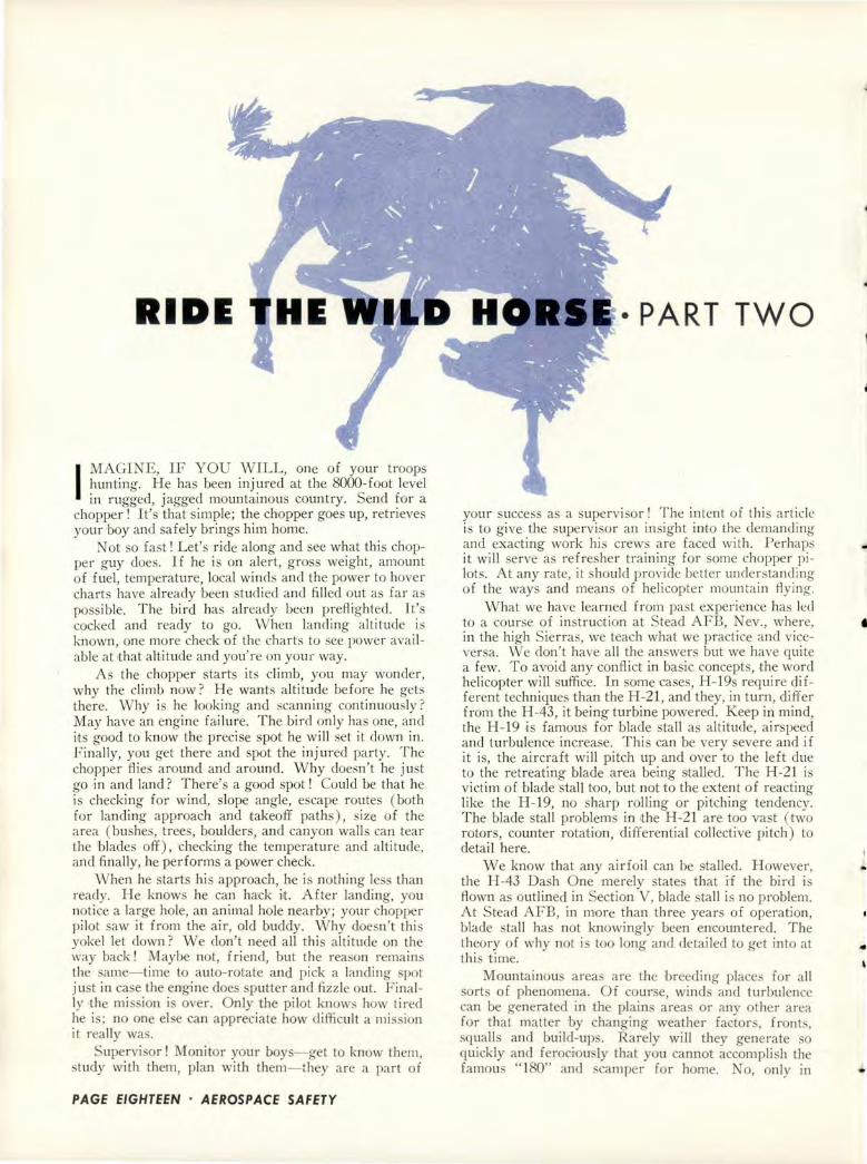
I MAGI NE, IF YOU W ILL, one of your troops hunting. H e has been injured at the 8000-foot level in rugged, jagged mountainous country. Send ~or a
chopper! I t' that imple; the chopper goes up, retn eves your boy an I safely brings him home.
Not o fas t! Let' ride along and see what thi s chopper <T UY does. If he is on alert, gross weight, amount of f uel, temperature, local win ds and the power to hover charts have already been studied and filled out as fa r as pos ible. T he bird has already been prefiighted. Jt' s cocked and ready to go. W hen landi ng altitude is known, one more check of the charts to see power avai lable at t hat altitude and you' re on your way.
As the chopper tar ts its cli mb, you may wonder, why the cli mb now ? H e wan ts alti tude before he gets there. vVhy is he looking and scann ing continuou Iy? May have an engine failure. The bird only has one, and its good to know the precise spot he will set it down in. Fi nally, you get there and spot the injured party. The chopper fli es around and around. Why doesn't he just o-o in and land ? There's a good spot ! Could be that he is checking for wind, slope angle, escape route ( both fo r landing approach and 1takeoff paths), size of the area (bushes, trees, boulders, and canyon walls can tear the 'blades off ), ·checking the temperature and altitude, and finally, he performs a power check.
When he sta rts h is approach, he is nothing less than ready. He knows he can hack i•t. After landing, you not ice a large hole, an animal hole nearby; your chopper pi lot saw it from the ai r, old buddy. W hy doesn't thi s yokel let clown? We don't need all t his altitude on the way back! Maybe not, f riend, but the reason remains the same-time to auto-rotate and p ick a landing s1 ot just in case the engine does sputter and fizz le out. Finally 'the mission is over. Only the pilot knows how tired he is; no one else can appreciate how difficul t a mission it really was.
upervisor! Monitor your boys-get to know them, study with them, plan with them-they are a part of
PAGE EIGHTEEN · AEROSPACE SAFETY
·PART TWO
your success a a supervi or! The intent of this article is to give the supervisor an insight into the demanding and exacting work his crews are faced with. Perhaps it wi ll se rve as ref resher training fo r some chopper pilots. At any rate, it should provide better understanding of the ways and means of helicopter mountain flying.
What we have learned f rom past experi ence has led to a course of instruction at Stead AFB, ev., where, in the high Sierras, we teach what we practice and viceversa. We don't have all the answers but we have quite a few. T o avoid any confl ict in basic concepts, the word helicopter will uffi ce. In some case , H -19s require different techniques than the H-21 , and they, in tu rn, differ from the H-43, it being turbine powered. Keep in mind, the H -19 .is famous for 'blade tall a altitude, ai rspeed and turbulence increase. T his can be very evere and if it is, the aircraft wi ll pitch up and over to the left due to the retreating blade area being talled. T he H-21 is victim of blade ' tall roo, bu t not to the extent of reacting like the H -19, no sharp rolling or pitching tendency. The blade stall problem in 'the H-21 are too vast (two rotors, counter rotation, differential collective pitch ) to detail here.
W e know that any airfoil can be stalled. However, the H-43 Dash One merely state that if the bird i flown as outlined in Section V, blade stall i no problem. At Stead AFB, in more than three years of operation, blade stall has not knowingly been encountered. The theory of why not is too long and detai led to get into at this time.
Mountainou areas are the breeding place for all sorts of phenomena. Of course, winds and turbulence can be generated in the plain areas or any other area for that matter by changing weather factor , fronts, squalls and build-ups. Rarely will they generate so quickly and ferociou ly that you cannot accomplish the famous " 180" and scamper for home. o, only in
•
•
..
mountainou terrain can one valley be peaceful and offer no resistance while the next one offers so much in the testing of your skills and know-how and proof of the olidity of your aircraft and how well and how sturdy
it has been built! I'm sure we are all familiar with the old expression, ''Flying is hours and hours of utter boredom, punctuated by moment of stark, raving, terror." We know that experience is a hard teacher because she general~y gives the test first, the lesson after&ards. How, then, can we prepare ourselve for these unexpected and unpredictable factors which involve the safety of our bird, our crew and ·our passengers? U nforttmately, there are no hard and fast rules to follow. The rules are as infinite as time or space. Each experience will probably never happen again in the same place, in the same sequence or to the same crew or to any other crew who comes rattling along.
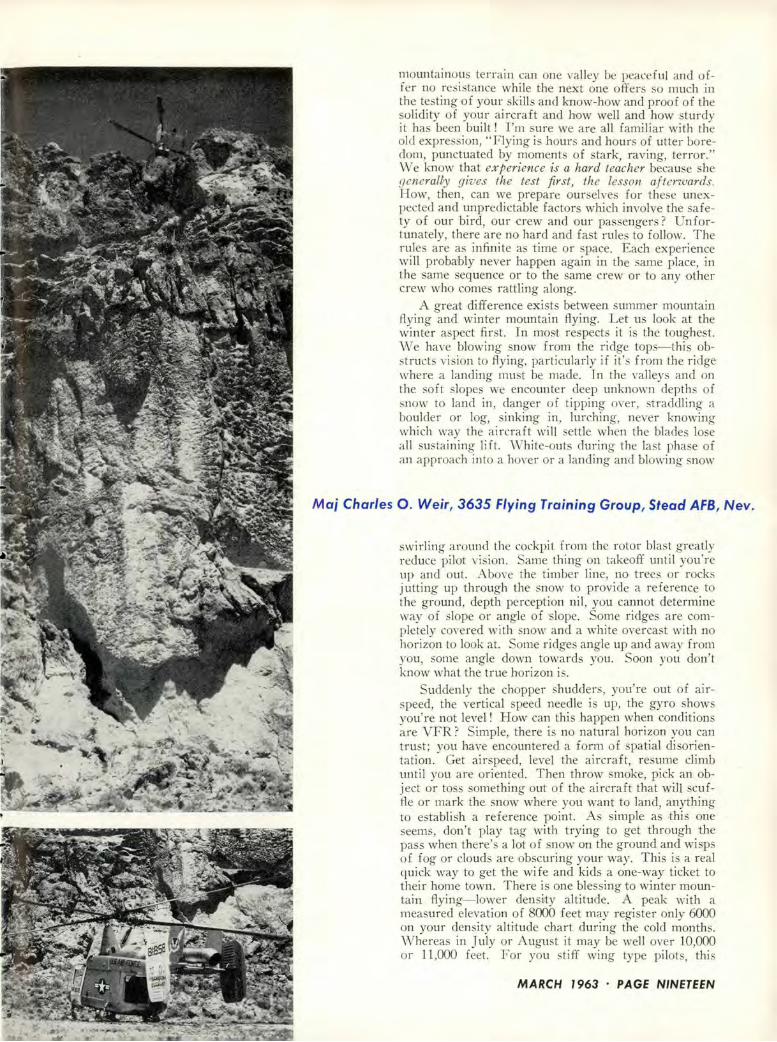
A great difference exist between summer mountain flying and winter mountain flying. Let us look at the winter a pect fir st. In most respects it is the toughest. We have blowing now from the ridge tops- thi obstructs vis ion to flying, particularly if it's from the ridge where a landing must be made. In the valleys and on the soft slopes we encounter deep unknown depths of snow to land in, danger of tipping oYer, straddling a boulder or log, sinking in, lurching, never knowing which way the ai rcraft will settle when the blades lose all sustaining li ft. ·white-outs during the last phase of an approach into a hover or a landing and blowing snow
Maj Charles 0 . Weir, 3635 Flying Training Group, Stead AFB, Nev.
swi rling around the cockpit from the rotor blast greatly reduce pilot vision. Same thing on takeoff until you're up and out. Above the timber line, no trees or rocks jutting up through the snow to provide a reference to the ground, depth percepti·on nil , you cannot determine way of slope 01· angle of ·slope. Some ridges are completely covered with snow and a white overcast with no horiz·on to look at. Some ridges angle up and away from you, some angle down towards you. Soon you don't know what the true hor·izon is.
Suddenly the chopper shudders, you' re out of airspeed, the vertical speed needle is up, the gyro shows you're not level! How can this happen when conditions a re VFR? Simple, there is no natural horizon you can trust; you have encountered a form of spatial disorientation. Get airspeed, level the aircraft, resume climb until you are oriented. Then throw smoke, pick an object or tos s·omething out of the aircraft that will scuffle or mark the snow where you want to land, anything to establish a refe rence point. As imple as rt:hi s one eems, don't play tag with trying to get through the
pass when there's a lot of snow on the ground and wisp of fog or clouds are obscuring your way. This is a real quick way to get the wife and kids a one-way ticket to their home town. There is one blessing to winter mountain flying- lower density altitude. A peak with a measured elevation of 8000 feet may register only 6000 on your density altitude chart during the cold months. \Vhereas in July or August it may be well over 10,000 or 11,000 feet. For you stiff wing type pilots, this
MARCH 1963 · PAGE NINETEEN
RIDE THE WILD
HORSE
amounts to lengthening the runways in the winter and shortening them in the summer. The lower the density altitude, the more safety factor we have. Fly your marginal missions if possible in summer or winter with lightened aircraft at or before sunrise and at or after sunset. You would be surpri ed at the increased afety factor this will provide.
Take away the snow and most of the problems mentioned disappear. In the summer time, rain squalls are to be avoided, carburetor heat monitored and caution still exercised to the utmo t. Wet grass, rock and mud can cause wheel slippage, roll the bird over, or start an avalanche! Check slope limitations in the Dash One. Anything over 20 degrees is real hairy. You may have to hover with the nose wheel on the ground, forward rotor tips inches away from obstacles, the rear wheels eight feet up-still flying. Use the hoist for your transactions; don't be stubborn and try to continue a landing. For the more difficult mi sion, land downhill a couple thousand feet. Off-load anything you can then try again. } or the impos ible mission, land downhill somewhere where there is no sweat and let your work party climb up to where the job is. Bravery and determination are admirable traits but serve as lousy excuses for avoidable accidents!
Some pilots may like to tay within handshaking distance of the ground as they climb up through the valley and slopes. The smart pilot will climb before he gets there. Cro s the ridges high. If you get caught in a sudden downdraft, there is time to peel off one way or the other to gain airspeed; power alone, in most case , is not sufficient. The only times you should be close (a minimum of 500 feet) to the ground is when you evaluate your intended landing area, power check it, approach it, land on it and depart it. At all other time , it is healthy to have altitude.
Get behind the speed curve on the approach or on the takeoff and, buddy, you had better have a patch -elected where you can lower the nose and zoom away into translational lift. Settling with power can stain your aircraft with chlorophyll from the vegetation beneath you! Beware of the irregular and jagged peak . They break up the wind flow and will hurl turbulence at you in a million pieces and from a many directions.
To develop your wind consciousne s, you not only have to know how to hunt for wind, but also where to
PAGE TWENTY • AEROSPACE SAFETY
find it. An experienced quail hunter would not think of wa ting his time and effort hunting where he knew there were no bird . The wind hunter knows that downdrafts are on the leeside of the slope. He also suspects wind currents to be down slope in the morning and up slope in the afternoon. Areas of unlight and hade can be tricky. As you fly from a sunlit area into the shadow of a mountain, you can expect a burble of turbulence. I have observed as high as ix degree temperature change in going from one to the other. Cool air settle and ;lithers its way down lope. Warm air is displaced and rises in the same manner.
The smart pilot knows that the wind rolls and curls over the ere t of ridge and creates a bubble or wirl that can snatch your aircraft and toss it up and clown. Yes, this pilot is continuously scanning for wind indication , moke, rippling gra s, bushe , tree , water ripples on a lake, birds on the takeoff-I don't know of any that takeoff downwind. A continuous watch will keep you fairly informed. You can dogleg and check your drift. For high landings, moke grenades provide the best wind indicator. Smoke will provide you with three es-ential bits of information- wind speed, amount of boil
and velocity. But it has its drawbacks. Drop it in ide the chopper and you're in real trouble. To sed into weeds or a high and dry timber area, it can start forest fires.
We have already mentioned weight but keep in mind, the higher the landing, the less your gross weight should be. Years ago, the H -5 and even the H-19A Dash Ones outlined what we referred to as a diminishing o-ro s weight factor-150 pounds for each 100 feet of altitude. For takeoff at sea level, you could fully gross the chopper, say at 7000 pound . BUT for landing at a density altitude of 6000 feet, your gross had to be 5950 pounds. From rule of thumb procedures uch as these, our performance charts have slowly gone through the proce s of evolution and are now trustworthy charts-use them !
Another thing we often overlook-straight wing pi lots are cleared to crui e and maintain 10-11-12-15 thousand feet. They are required to use oxygen, which i not news to us. BUT, how many of you chopper people have a portable bottle with you when it' necessary to
..
..
1
..
work at 10,000 or over ? With lhe coming of turbine powered choppers we can assume that helicopters will be call ed in to do jobs the piston engine choppers couldn't hack. A few years ago, I had occasion to work Mt. McKinley up to 16,SOO feet. Our daily operations were from sea level to at least 12,000 feet. Who thought of using oxygen in a chopper during rescue missions? No one ! I su pect that two fliers died on this mission clue to no oxygen. Their Cessna 180 was last seen in a turn, then a plume of smoke, and all was quiet at 18,000 feet. We think, "Me need it ? Don't be foolish, I'm climatized ." Little do we realize that our reaction time is the first victim of thi hallucination. We know who the second victim will be. I hope to see the clay when our choppers have built-in oxygen systems. There's little room in the cockpit of today's helicopters to accommodate even a walk around bottle.
Obstacles to landing approaches and takeoff routes are alway of the utmost concern to the chopper pilot. There are three items to be checked during landing si te evaluation-the height of the obstacles, the ize of the clearing and the loss of wind effect. The sharp pilot will not commit himself to landing until he has figured out whether and how a safe takeoff can be made. In most cases, the size and height of approach obstacles are closely related to the size area required to safely land and takeoff from. Too many times, pilots have landed in an area like the bottom of a barrel and, when takeoff time came, hit the fir t obstacle trying to climb, zoom or claw their way up and out. Sometimes, even a maximum performance takeoff is a feeble attempt to get airborne. Obstacles should be given all respect necessary. In ome cases, 180-clegree approaches and 90-clegree approaches are necessary to avoid obstacles to landing.
Approaches should be made as nearly into the wind as possible and over the lowest obstacles. The same applies to takeoff . Who can say whether for this particular takeoff the pilot should head into a 10-knot wind and attempt to clear a 100-foot obstacle in SO to 7S feet? Would it be better to turn 20 degrees right and utilize 100 feet of run and then pull up over a SO-foot obstacle? Only the pilot can determine which method is the safest to attempt. There i a whale of a difference in whether the load is being carried into a particular clearing or out of it. Less room is required to carry the load in, more to lift it out. When the throttle is full open, the blades have maximum angle of attack and the manifold pressure needle is as high as it will go-you're not about to lift a load up over any obstacle ! For the same reason, when carrying loads into high density altitude areas, a rate of descent of no more than 300 feet per minute is recommended. Anything higher than that can put you behind the power curve again. As you near the ground, sink rate may be so great that full power will not stop it. Settling to the ground and impacting on a ridge at 300 feet per minute can be a hairy situation. Only when you control airspeed, approach angle and rate of descent can you assure yourself that you have it made.
This is not the time to manhandle the control . Gentle stick movement are neces ary. You must be slow enough in the final stages of leaving translational lift behind you, at about 12-14 knots of airspeed, to
allow lhe ground cushion lo catch up to the aircraft and sustain it as you gently add what available power is left. At altitudes of 10,000 to 12,000 feet, a 100-foot per minute rate of descent during the approach is certainly the most de irable. The reason is simple- it doesn't take a sharp surge of horsepower to stop the rate of descent.
Even in the USAF Survival School here at tead AFB, we teach the survival students a bit about heli copter operating conditions and limitations. In case of bailout or forced landing, chances are, rescue will be effected by helicopter. Too many times survivors haYe placed themselves in locations where a helicopter cannot get close enough to land or el e a difficult hoisting job has to be accompli shed. If you anticipate rescue by chopper, then there a re three factors that you should consider. In helping the chopper pilot, you are certainly helping yourself. Consider the altitude of your location, the terrain and obstacles and the influence of the direction and velocity of the wind. These items will a ist you in the selection of a uitable landing place where the pick-up can be accomplished. You will have clone your part. The rest is up to the chopper man.
In the USAF Helicopter School, we teach the only sure method that ha yet been devised to get in and out of mountainous confined areas of operation. If you cannot use these guides and if the power check doesn't give you the tolerance we recommend, then friend, you had better seek another line of business to get into ! We stress land ing site selection, landing site evaluation, high reconnaissance, low reconnaissance, power check, approaches, hovering and landings.
Next month we'll look into the details of each. * • • •
" I must be in anothe r blind spot."
MARCH 7963 · PAGE TWENTY-ONE

• • • MISSILANEA GAR-ZA. During a practice intercept, the pilot of an F-101 attempted to clear an abort signal by going to the trigger salvo position on the armament selector panel with the trigger depres eel. Two GAR missiles jettisoned unarmed into the ocean. Probable cause was that the pilot was a former F-102 pilot and through habit used the F-102 FCS procedure for clearing an abort in the F -101. As corrective action, it has been recommended that air crew be instructed to select the FCS position on the armament selector panel when attempting simulated GAR attacks. This allows the pilot to pull the trigger and eliminates the abort "A" signal.
• • • THE LOAD CREW wa dispatc~ed to download
GAR from an F -102A. In attemptmg to open the doors the load chief was unable to get a reset light ( no snubbing pressure). He then proceeded to use the emerO'ency procedure as outlined in tep 1-26(A), TO lFlOZA-2-12 to open the doors. pon obtaining re et light and snubbing pressure, the door were actuate<i to the open position. The <ioors opened and the aft launcher free fell (without pres ure). The center missile in the aft bay caught in slots of the bay door, ripping the bottom stabilizers from the missile. The nirdomes on the missiles on rails 5 and 6 were scratched.
Probable cause: The aft launcher selector vah·e f<tilecl after the aircraft became airborne, causing the aft launchers to fall in Aight. If the aft launchers were to fall after the fon,·ard launchers and doors were close<i, this would not release snubbing pre sure from the armament sy tem that remained snubbed. \ Vhen the aft interlock cit:cui t is broken. (by launcher or launchers becoming unlatched) it is impossible to obtain reset by normal mean . Prior to loading the aircraft, launchers an<i bay doors were operated through one complete cycle. Rigging of missile launchers was checked, after the incident, with negative result . Mis ile rails 2 and 3 were in correct adjustment in accordance with 1F-102-943. Missile rails 1, 3, 4, and 6 were in correct adj ustment in accordance with IF-102-2- 12 with negative result . The armament system was also Yisually checked for moisture and dirt in the pneumatic lines with neO'ative result . The aft mi ile launcher elector ,-ah·e was removed and replaced with a new item which eliminated the malfunction . The remoYed elector nlve \\·as checked by all methods with no discrepancy noted.
uspected causes : ( 1) Aft launcher rails not rigged in accordance with tep 4-52, TO 1F-102A-2-12. This woul 1 allow the rails to become unlatched after snubbing air had been removed allowing the missile to free fall and ride on mi sile and bay doors. (The aircraft had flown just prior to download.) Rigging was checked with negative re ults. (2) J.tfalfunction of the electrical portion of the armament pneumatic ystem which might cause missile rails to unlatch and free fall. Jf this was the cau e then there would have been an un nubbecl extension; however, electrical checks were performed in accordance with TO 1F-102A-944 with negative re ults. Additionally, operational check were performed, after the elector valve was replaced, in ac-
PAGE TWENTY-TWO · AEROSPACE SAFETY
cordance with steps 3-25 and 3-30, TO 1F-102A-2-12. The system operated normally .
RECOMMENDATJ ON: Emergency Action, AFTO Form 22, Technical Order System Publication Deficiency Report, RCS: FLC-Kl14, was submi tted recommending the following be entered in TO 1F-102A-2-12 after 1-26: Caution, \\'henever missile are aboard aircraft the following procedure should be followed. (A) Disconnect the pneumatic actuator from right and left hand flipper doors by remm·inO' the four flush head bolts that hold each actuator . ( B) Inspect and in ure that the missiles are properly latched and locked. (C) In the event that mis iles are not latched, e\·ery effort should be made to latch and lock missiles, prior to implementation of emergency procedures. (D) If the abm·e step is not accomplished prior to implementation of emergency procedure, damage could be caused to mi sites and the weapons system, providing missiles \\'ere not properly latched and locked.
• • • GAR CHECKLIST AG IN. During do\\'nloading of an F-102A. the missile on rail Nr 2 slid forward. a the rail was being manually lo\\·ered, and struck the fon,·a rd bulkhead damaging the missile radome and guidance unit. Damage was extensive enough to require depot repair. Apparently a crewmember failed to make sure the missile was locked to the raiL AI o the GAR 1 and 2 loading checklists do not include a double check of missiles locked on launcher.
• • • A GAR-3A \VAS LAUNCHED during a firing
mi "Sion from an F -106 with the target below 500 feet . :Niissile preparations and launch sequences were normal. The missile launch and initial boost appeared to be normal. At approximately the termination of initial boost, the mi ' ile disintegrated with an explosion tha t \ras hea rei in both cockpits. Parts of the missile went over the launching aircraft. One piece of the mis ile, about two feet long and six to eight inches wide, pas eel within 10 feet of the canopy. The aircraft was not damaged but the aircrew members were slightly excited.
The cau e was undetermined. Both the pilot involved and the pilot of the chase aircraft are of the opinion that the missile di integration was caused by warhead detonation and not motor blow-up in flight. There was no recovery of missile parts or pieces from the water range. *
...
I ..
•

...
OUR TELEVISION S C R E E N S are littered nightly by a collection of
corpses and sorely wounded as the good guys and the bad guys shoot it out. Meanwhile, back at the Air Force base, there are other shootings. These aren't shoot-outs between the goods and bads-they are unintentional shootings of fellows like you and me who are neither goodies nor baddies but just plain guys. What's going on here?
What's going on is that carelessness with firearms is costing the lives of some Air Force personnel and the wounding of others. These are the direct results. Who knows the other potential hazards when a weapon is accidentally discharged?
Through the first eight months of 1962, there were 122 wounded and nine killed from the accidental discharge of small arms. For example:
An airman was wounded when he failed to follow accepted safety procedures. After drawing a .45 caliber pistol he failed to let the slide go forward prior to inserting the clip and placed the weapon in his holster. Later he noticed that the slide of the weapon wasn't forward and drew the pistol from his holster. Holding the weapon with his left hand partially extended in front of the barrel, he allowed the slide to go forward, then pulled the trigger. The gun fired and the bullet grazed the fleshy part of his hand.
This airman had been an air policeman for more than two years, and was qualified as sharpshooter with the .45 and expert with the .38.
* * What could have resulted in a real
disaster occurred when a guard accidentally discharged his weapon and the bullet punctured a B-47 fuel tank. The fire department was called immediately and firemen kept the ramp washed down while the tank was de-fueled.
Although the airman claimed that the weapon accidentally fired while he was clearing it, investigators concluded that he was practicing his quick draw. Other sentries reported they had observed the airman practicing the quick draw while walking his post on the day of the accident.
This airman was considered well qualified for his job and highly motivated. He admitted, however, that he became very restless during the long hours of walking his post with no one to talk to.
* * * Weapon mishaps are not confined
to duty hours. An officer accidentally shot and killed himself in his home. Apparently he was handling a .22 pistol which discharged, wounding him in the chest.
* * * A small oversight can be ex-
tremely dangerous. An airman was posted in the alert area at which time he inserted the magazine into his pistol. He recalled later removing the pistol from the holster in preparation for an inspection. He did not take the magazine out and apparently jacked a round into the chamber. A few minutes later, as he moved the holster to a more comfortable position on his hip, he touched the trigger and the weapon discharged, wounding him in the leg.
* * * This one involves two airmen, one
armed with a .45 pistol, the other a .30 carbine. The men were on adjacent posts and got into a conversation on how fast they could
draw. The man with the carbine asserted that he could get his carbine off his shoulder and jack a round into it before someone else could get a .45 clear of the holster.
When the man with the .45 went on a break, he removed the clip from his weapon and did not remember reinserting it. Later, as he walked toward the other airman, he saw him take the carbine off his shoulder and thought he was trying a fast draw. He pulled his pistol from the holster and pulled the slide back. The gun went off, wounding the other man in the leg.
Like many of our accidents, the accidental firing of weapons is totally inexcusable. Most of us receive a lifetime indoctrination in the hazards of firearms. By the time a man is old enough to carry a weapon on duty he should-unless he is a complete idiot-thoroughly understand the hazards of mishandling firearms and the proper procedures for hancUing the weapon assigned to him.
The above examples are just a few of many. They were selected because in every case the participants were thoroughly trained, had a lot of experience and were considered well qualified in the handling of fireanns.
Horseplay and fast draw are for TV cowboys and small boys with toy pistols. These are not for adults with lethal weapons. One man we know recently shot himself in the leg while quick drawing a pistol. The bone was shattered and damage to nerve tissue cannot be completely repai reel. He wears a steel brace and will never walk normally for the rest of his life. That's really learning the hard way.
The Air Force has detailed, written instructions on the handling of firearms; training is thorough; command and base SOPs cover every conceivable detail. Nevertheless, we will continue to have injuries and deaths, not to mention ' damage to equipment, as long as men fail to realize that they are men and not little boys with a fascinating plaything. *
MARCH 1963 · PAGE TWENTY-THREE

DID YOU EVER DRIVE miles out of the way becau e someone gave you the wrong directions? O r find out that the man at the gas station fo rgot to tell you about a long detour? Jf that ha happened, you must have wished there was some way to get the right information soon enough to avoid all that trouble-detours, bridges out and other obstacles. Maybe you
wished for a OT AM system for automobile traveler : a good, accurate system, one that was speedy, too. Well, that's what every pilot want : a good, accurate, speedy system that gives him the riaht information in time. For him the consequence are much more serious than for you on a vacation trip. Every time a pilot asks for flight information, he needs to be told the latest, and the most accurate information. If there's a NOT AM mi ssing, or if there's an old OT AM that should have been canceled, he can get into real trouble.
The purpose of this article is to clear up some of the misunder tan dings about the OT AM system, and invite your assistance in the new developments of the NOT AM sy tem that are de cribed in the new manual on NOTAMs (AFM 55-13, 15 Nov 62). (Since the old system was inadequate, we could only go one way with the new system. It could only be an improvement!)
Let's start with the duties of base operations person-
nel. When you're told that some of your faci liti es are on the "Fritz" you mu t decide whether to end a NOTAM. If you are not ure, look it up. It's in paragraph 1-2, Section B, of AFM 55-13. I£ a NOTAl\1 is required, prepare it in the prescribed format (se Chapte r 4) and deliver it to the base weather station who will send it to the Central OTAM Facility ( CNF), at Tinker AFB, Oklahoma.
Allow the CNF about 30 minutes to proce s the NOT AM and send it out to all stations. Then, check your incoming NOT AM to see if it has been received. Jf it hasn't arrived within one hour, find out what happened. Depending on the urgency, either send the CNF a message or get on the phone and find out what happened. If the C F is not going to process it, they will contact you. If the CNF duty officer and your Baseops people don't agree on whether the NOT AM should be published, your Baseops officer may over-ride the CNF duty officer and insist that the NOT AM be published, but he must give his name, rank and erial number.
He should remember, though, that sending nones entia! information may defeat the whole NOT AM system. There is only a limited amount of circuit time available, and if it is exceeded, other information-more vital to safety-may be neglected. Review your manual thoroughly on this point, e pecially the illustrations. Most cases are easy to decide. Only a few in the gray area may have to be explained to the C F. Remember, the
NF duty officer is wearing a blue suit too. He i a pilot as well as a qualified operations officer and he is trying to do what is best for the whole system.
When you receive a new NOTAM, don 't wait for
IS YOUR NOTAM SHOWING ? ·
PAGE TWENTY-FOUR · AEROSPACE SAFETY
other NOT AM before po ting it to your summary. We realize that there will be times when you are too busy to devote constant attention to your NOT AM display, but a little more effort from you makes a big difference in ervice to the pilot. In any event, be ure your summary is updated as often as possible, at least once an hour.
But the mo t important thing i accuracy. When you get a new ummary, check it immediately to be sure the information about your ba e i accurate . Make sure that all active NOT AMs about your base are there and that the canceled NOT AMs on your base have all been deleted. If you find an error, notify the CNF immediately. They have no means of determining this type of accuracy except to depend on you.
After you have checked the summary thoroughly, make sure it is posted on the display board correctly. That is, post Part 1A in the first column, Part 1B under the Temporary Base NOTAMs columns, and all of Part T1 (A&B) under the "FLIP CHANGES" column.
ext, de troy the old summary (the part it replaces) and all of the related individual OTAMs. (You need not po t a summary or individual NOT AMs on any overseas areas unless your base requires this information.)
T he A ir Force needs your best imagination and ..
...
L
initiative to help the pilot. You might post a checklist near the OTAM display, together with a li t of all authorized abbreviations. Base operations officers should insure that all pilots arc given an up-to-elate briefing on the NOTAM system while they arc in instrument ground school training.
Now let's look at NOT AM from the pilot' · standpoiD:t. ~fter you have determined the route of flight, destmat10n, and alternate airfields, here is the way to check the NOTAMs on your flight:
• Check Part lA for information on general areas. • C~eck Part lB for terJ?inal information on your
de tmat10n and alternate aiPfields; this covers both USAF and USN bases. If you are clearing for a civil ~irport (?r using one a an alternate), request OT AM m~ormat10n from the Baseops dispatcher who will obtam It from the neare t FAA Flight Service Station. Under the USAF/USN NOTAM System, you will get NOT AM info on terminal navigational aids, regardless of w~o operates or maintains the facility, that will affect termmal procedures at a USAF / USN installation. If you need en route NOT AMs, you obtain them from FAA Flight Service through the Baseops eli patcher.
• Check Part II, NOT AM Summary for any changes to the FLIP.
• When you are clearing from a civil airport, you can get USAF / US NOT AM information by placinoa collect telephone call to one of the six USAF Weathe~ NOT AM briefing facilities. These are all listed under Weather/NOT AM Briefing Procedure in the En Route Supplement.
• If you need NOTAM information on USAF/ US facilities while airborne, call the nearest USAF 1 US base. If you need information on civil terminal or en route facilities, call the neare t FSS.
There are two actions under way to ease you1· use of the system. Soon, the En Route Supplement will identify each location covered by the USAF / USN NOT AM System. Also, the abbreviations listed in the En Route Supplement are being expanded lightly and only those listed will be authorized for NOT AM use.
Now let's take a look in the crystal ball. You may be interested in knowing some of the chano·es that FAA is planning which will aff·ect our sy tem ~nd help simplify your work.
• The Federa~ Aviation Agency has recently installed an electromc computer and associated automatic e9~ipment which will make it possible to issue a daily ClVll NOTAM Summary, through a revised FAA NOT AM System similar to that of the Air Force and the Navy. This ummary will be in clear text and will be available in most USAF / US operations offices via
I
MEN WORKING
FAA Communications System (Service "A"). When this sununary b~comes available, the Baseops people should post It with the standard NOT AM display- at the bottom of the first column. This summary will mean that the pilot will no longer need to request civil terminal and en route NOT .A:M from the Flight Service Stations.
• Plans are also under way to dispatch the USAF/ USN NOTAMs to the FAA Flight Service Stations for advisories in flight.
The_ USAF and USN are studying the possibility of processmg another, separate, ummary for en route NO! AMS. Several ~netho_ds of publishing this information are under consideration; the most promising may be the arrangement of NOT AMs by navi o-ation chart designation. o
Soon. the USAF / USN System will be standard, world-wrde; the European-Mediterranean areas are well und_er _way with the new plan, and the Pacific area will begm Its modernization program early in 1963, so that wherever you are, the system will be standard. You'll see the same eli play at each US~F / USN airport, and know how to use It Without additional instructions or coding or decoding. '
The NOT AM System of the future may, eventuall_f, operate as a common system, integrated under a ~ mgle ag_ency, that will furnish both military and civil mformatron. Un?er thrs system, OT AM information wo~ld be stored 111 a central c?mputer system and kept theie. _Then wh~n .fOU, the pilot, are ready to submi t y~ur flight plan, It ~Ill be fed mto the computer. Then it Will be_ returned With all the information needed for your flight.
However, that known ultimate will not be with u fo: a while. Advances in the NOT AM program are bemg made step by step. We must perfect the present system before we go on to the next phase of automated NOTAMs. In the meantime we are trying to get all of the bugs out of the present ystem. To do this we must hc:ve the pertinent NOT AMs quickly, accurately, and w1 thout unnecessary information.
Finally, if it takes us as long to perfect the new syste~n as it d!d to get rid of the old one, your grandson will be gettmg a NOT AM that "the space platform between Mars and Venus has moved slightly out of positi?n ~,000,000 miles to the apogee" (You tell me the directwn 'cau e I ?on't know which way is up.) ! So, troop , let's get with the program. Isn't it time to go update that summary again? *
Maj Charles H. Metzger, Hq USAF NOT AM Action Officer

AT TAKEOFF for a routine transport mission, the gross weight of the C-124 was 180,910 pounds. Weather at takeoff was ceiling 1000 feet, visibility three miles in light snow, decreasing to one mile in snow showers in the approach zone. During the GCA monitored climbout and when the aircraft was one-half mile beyond the end of the runway, the pilot called GCA and requested a clearance to return for a landing. Immediately afterward, the GCA controller heard the pilot ay, "Pull power on Number Two," a transmission apparently intended to be on interphone.
The aircraft climbed to 1800 feet msl, and the G A controller vecto red the aircraft into the pattern for landing. The GCA pattern was flown in a normal manner until the ai rcraft reached the glidepath on final approach. Three and one-half to two and one-half miles from touchdown, the GCA controller advised the pilot, "Forty feet low, one hundred feet low, dangerously low, and go around, acknowledge."
Ground witnesses first ob erved the aircraft approximately one and one-half miles from the approach end of the runway, at an altitude of 150 to 200 feet above a beach that bordered the airfield. At thi altitude, the aircraft was SO to 100 feet below runway elevation. One mile from the end of the runway, the ai rcraft was observed in a shallow right turn with a nose high attitude. At this time additional power wa applied and the aircraft ascended briefly. It then stalled abruptly and the left wing dropped. The aircraft struck the ground left wing first and was destroyed by impact and subsequent fire . The eight crewmembers and three passengers were killed. Three passengers received major injuries and one received minor injuries. The pilot had a total of 5608 flying hours, of which 526 were flown in the C-124.
The primary cause of this accident was that the pi lot did not maintain sufficient airspeed in turbulent air during final approach, and allowed the aircraft to stall while attempting a GC with one engine inoperative. An area of extreme turbulence exists in the approach zone to the runway. The N r 2 propeller had been feathered following fail ure of the r A-2 cylinder.
DURT G A SIM LA TED TWO-E GINE PPROACH at night, the pilot and instructor pilot allowed the aircraft to sink too low on final approach. The C-124 hit the ground in a three-point attitude 879 feet
PAGE TWENTY-SIX · AEROSPACE SAFETY
short of the runway. Power wa immediately applied to all four engines and the aircraft regained flying speed. The gear would not retract and upon inflight inspection, the nosewheel strut was discovered to be broken. A fuel leak was also detected in the r 2 main tank. Most of the fuel remaining in the damaged tank was transferred and the aircraft was flown until the tank was empty. When the tank was dry, a landing was made on the main gear with the nose gear being held off the runway. After rolling several hundred feet, the ri aht main gear collapsed and the aircraft lid to a stop on the nose and right wing.
This was another pilot factor accident, in that the pilot and instructor pi lot failed to judge properly the altitude and speed necessary on the final approach to landing. The secondary cau e was their fai lure to use the proper flap setting for a two-engine landing.
Mai Gam H. Harward, Transport Br.
B-52 INFLIGHT FIRE incident reports and EURs continue to be received reporting inftight crew compartment fires in the B-52 aircraft re ulting from personal equipment being placed on or in the vicinity of a heating duct.
The offending duct enters the upper compartment at the aft edge of the ladder hatch and runs aft on the EWO compartment floor. N umerou rubber mattresses and other items of per onal equipment have heen set
...
1
-

•
...
-r
D
afire by contact with this duct. Several organizations have installed locally devised shields to eliminate this hazard. AFLC has recognized the problem and issued TO 1B-52-1507. Prompt ordering and installation of kits by u ing organizations should eliminate this serious hazard.
* * LOSS OF CONTROL - Over the years, loss of
control resulting from poor pilot technique has been a major factor in B-52 accidents. Although we have not lost a B-52 from this cause since January 1961, two recent incidents point out the ever present danger. Both of these incidents occurred during Chrome Dome missions with only one pilot in the cockpit and both came very close to disaster. In one case the loss of control was due to lack of oxygen discipline and resultant hypoxia of the pilots. Structural damage to the aircraft was incurred before the aircraft was brought under control. A contributing factor here was failure of the pilot to switch to "alternate source" for cabin pressurization when engines N r 3 and N r 4 were shut down.
The second incident occurred with the copilot flying ,,·hen clear air turbulence was encountered. The aircraft apparently stalled and lost 13,000 feet before the pilot returned to his seat, added power and regained control.
Both of these crews are lucky to be alive. The B-52 is one of the safest aircraft in the Air Force inventory, but generally does not give you a second chance when allowed to get out of control. Oxygen procedures and turbulent air penetration procedures are adequately covered by the Flight Handbook and Air Force Regulations.
Lt Col Robert P. Rothrock, Bomber Br.
FUEL FILTER DEICI G SYSTEM- A Safety of Flight Supplement, 1 T-39A-(SF) 1-29, was recently issued for T-39A and B airplanes. The purpose of this
supplement is to provide additional instructions on the use of fuel heat during flight when flight is conducted in subfreezing temperatures. These instructions are as follows:
• BEFORE TAKl.':OFF: Turn the fuel healer switch ON for one minute just prior to takeoff. The fuel heater switch must be OFF during takeoff.
• INFLIGHT: The fuel heater switch should be turned on for one minute every 30 minutes.
• DURI JG LA DI G: Turn the fuel heater switch on for one minute in the traffic pattern. The fuel heater switch must be turned off on final approach.
Since the issuance of the referenced Safety of Flight Supplement, reports indicate that some T -39 pilots are becoming unduly concerned about the requirement to turn on the fuel heater switch for one minute every 30 minutes. Actually, this requirement is not as exacting a it may appear, since only a normal degree of diligence is needed. No harm Kould occur if the fuel heat were to be left on for somewhat longer than a minute or if the interYal between applications of heat nried slightly from 30 minutes. This cycle of heat application will keep the engine fuel system free of ice. Failure to u e fuel heat could result in filter icing and illumination of the FUEL FILTER BLOCK caution light which would serve as a reminder to resume the use of fuel heat. HoweYer, on the other hand, too frequent or continuous use of the fuel heater could cause varnishing of the engine fuel system components, hastening the need for engine overhaul.
Tt is therefore preferable to restrict the use of the fuel heater to not more than a minute every half hour, although, as previously tated, this time cycle may be regarded as "approximate."
North American Aviation Operation & Service News
IN THE LAST NINE MONTHS of 1962 there "·ere nine drag chute failures on B-66 aircraft. Five of the nine were the result of chutes being improperly installed by the pilot. Damage included blown tires and bent gears. One aircraft went off the runway.
All users of the B-66 should insure that pilots are made aware of the proper method of installing drag chutes since loss of a drag chute can be the cause of a major accident.
Lt Col Earl F. McKenny, Bomber Br.
MARCH 1963 · PAGE TWENTY-SEVEN

AERO~~u~ Q :; 2: -... 2: 0 u
DURING TAKEOFF the C-131 was lifted off at 104 knots, five knots below desired takeoff speed. The right engine failed and the propeller automat_ically f_eathered at liftoff. The gear was not retracted 1mmed1ately which caused a reduction in airspeed. The climb toward power lines, 7000 feet beyond the end of the runway and 140 feet above airfield level, was probably made at about 96 to 100 kn'ots, minimizing the rate of climb. The flaps were raised before the aircraft reached the power lines, causing a further loss of climb so that a zoom was necessary to clear the wires. The zoom further reduced the airspeed which caused the ai rcraft to stall and settle to the ground. Although none of the persons aboard was injured, the aircraft was destroyed.
This accident was caused by poor technique and lack of knowledge of aircraft performance on the part of the pilot in that the ai rcraft was forced off before takeoff speed was attained, late gear retraction and premature flap retraction.
Maj Gam H. Harward, Transport Br.
AN ORR WAS RECENTLY FILED by a slightly unhappy pilot who had his T -Bird liberally peppered with rocks and dirt thrown up by blast from the engines of a KC-135 . It happened this way: A KC-135 was sitting on the runup strip next to the runway, waiting to cross.
"Behind him was our T -33 at the corner of the taxiway and at a 45-degree angle to the tai l of the ' 135. Also behind the ' 135 were two Navy SNBs making runup. When the KC-135 received clearance to cross, he throttle-busted the outboard engines to what appeared to be 100 per cent power and showered the three aircraft behind him and completely littered the ramp. The rocks blown were up to the size of golf balls and hammered the side of the T -33 and went into the props of the SNBs."
PAGE TWENTY-EIGHT · AEROSPACE SAFETY
To prevent future such incidents, tower operators should advise pilots when other aircraft are behind them. Furthermo re, smaller aircraft should not taxi too close behind la rge ai rcraft, either jet or recip.
The Dash One procedure for the KC-135 is to use the outboard engines on the KC-135 to avoid pushing up fo reign particles in the nose section. However, on a narrow hard surface, such as a taxiway, it may be better to use the inboard engines during taxiing.
ICED Q-SPRINGS - Throughout the cold season our B-47s are flying low as well as high altitude sortie with the ever-increasing chances of elevator Q springs icing up, causing loss of arti·ficial feel.
Loss of feel can create some tricky manipulations of the rudder and elevators on a pop-up or low visibility app roach for landing.
N ineteen cases of loss of feel in the B-47 were reported by the end of last October, so be prepared and don't get caught in a box. Review the procedures outlined on pages 3-87, 88 and 89 of the Dash One and prevent a possible "Undetermined" major aircraft accident.
Lt Col Da v id J. Schmidt, Bomber Br.
OFF FLAGS- Ponder the hazard implications of this one. Preliminary investigation of a minor accident isolated the failure of tl1e MM-4 attitude indicator to be an internal instrument malfunction. This failure was in the roll axi s of the indicator with no "OFF" flag presentation. It is considered possible that internal failure of the instrument could also occur and sti ll not give an "OFF" flag warning. The "OFF" flag monitors the power to the gyro and does not monitor the roll or pitch movement of the instrument.
Action is being taken to initiate a safety of flight supplement to warn that MM-4 malfunctions can exist that will not result in actuating the "OFF" flag. Further, it will advise that where dual equipment is installed, cross reference between pilots' and copilots' MM-4 attitude indicators should be effected before takeoff and during flight.
Lt Col H. D. Smithson, Tran sport Br.
...
l
-,
..

-..
,•
r Lieutenant General
William H. Blanchard
The Inspector General, USAF
ALL BASES IN THE UNITED KINGDOM except Lakenheath were closed because of fog or construction in progres . Forty-five B-47s deploying from the States were inbound at close intervals. I okayed the letdown. The main gear collapsed on the fifth aircraft to land and it was burning in the middle of the only runway. Five more aircraft were already committed and fuel reserves were inadequate to get to the open alternates.
I saw this in a dream-thank the Lord- and it was a nightmare!
The next day it wa still a nightmare. I could not get a burning B-47 off the runway in time, under these circumstances-nor had I the equipment or capability to do it in a war situation when gear failures from battle damage are frequent. You can't use a bu II dozer on a conflagration of that sort without frying the or era tor.
In mulling this problem over in my mind I remembered a scheme which I had suggested years before. It was apparently considered too simple, however, and had been summarily rejected without test. That day, with my dream still vivid in my mind we went to work to see if the scheme was feasible. We fabricated and tested a simple net of meshed cable. One Coleman tractor, making a wide circle around the simulated burning B-47, positioned the dolly mounted net. Then two tractors, one at each end of the rig, pulled the net into the wreck and, working like a team of horses, dragged the wreck clear of the runway.
Following our initial success we did further testing with British tank retrievers. We found that for a skidding pull or drag, lightweight winches, tractors or loaded trucks could handle a B-52. With the gear prefabricated and a crash crew trained, ten minutes clears the runway.
We submitted drawings together with costs estimated to be about $5,000 a set. Being very wary of our bureaucratic system, I made my own.
I saw a burning wreck on a runway the other clay and thought of the project Colonel Ray Dietzel \\'Orkecl out so thoroughly. I thought of the National Guard deployment to Europe and the ever-increasing How of air traffic through our i olatecl island bases. Those stepping stones across the Atlantic and Pacific which have no alternate for hundreds of miles- those are the slabs that must be kept open constantly. A bulldozer or tractor with cable and hook will not handle the flaming wreckage of a large aircraft. It requires special equipment of the type I have described.
Safety officers, this is your busine s. Let' check now to assure that you have the equipment and the
procedure for its use. * * * MARCH 1963 · PAGE TWENTY-NINE

• U. S. GOVERNMENT PRINTING OFFICE - 651215
-
i 1