Embed Size (px)
Citation preview
A Double-Pendulum Robotic Platform to Understand Human Balance Project Proposal
Authors: Kendall Lui, Ruoxi Peng, Stanley Tsang, Chenxiong Yi Team Name: Pivotal Moments
Date: February 10, 2017 Course Section: EME 185A - A03
Abstract The following report is a project proposal for the development of a double pendulum robot that can be used by researchers to study controllers derived from human balance studies and by the COSMOS high school program for teaching about control systems. Ranking needs established that a device meeting the requirements for research would meet and exceed those of a device for teaching; Needs for a research device became the priority. Primary needs are an accurate human model, an easy to use interface, and accurate data acquisition. Specifications with the size specification of a 2 ft tall model and minimum perturbation distance of 5 in were the governing mechanical design factors. Two cart concept ideas recurred; The first a trackless cart and the second a cart on a track. Pendulum arm concepts also had a common theme of being directly driven by the actuator or having a transmission system. A preliminary 10 week schedule was established with milestones on the completion of the simulation, mechanical design package, calculations of the mechanics, and the design report. An initial calculation set a project budget estimate of $500.
Table of Contents
Abstract 1
Introduction 3
Mission Statement: 3
Project Needs 4
Preliminary Specifications 4
Concept Generation 5
Preliminary Budget 6
Preliminary Schedule 6
Conclusion 7
Appendices 9 Appendix A: Stakeholders 9 Appendix B: Needs 9 Appendix C: Target Specifications 11 Appendix D: Internal Concepts 12 Appendix E: External Concepts Research 15 Appendix F: Internally Generated Cart Concepts Revisited 18
Trackless Design 18 Leadscrew/Ballscrew Design 18 Belt Drive Design 18
Appendix G: Internally Generated Pendulum Concepts 19 Internal Belt Drive 19 Direct Motor Mount 19 External Belt Drive 20
Appendix H: Budget 20 Appendix I: Gantt Chart 21
2
Introduction The goal of the Double Pendulum Robotic Platform is to make a versatile robot that can be used to research human balance and to teach the basics of control systems to high school students. Inverted double pendulum systems are often used to study dynamics and control systems due to their chaotic behavior. The project is to use a double pendulum model to represent a human and use controllers to stabilize the chaotic dynamics caused by perturbations. In the scope of research, the robot will give researchers the ability to test the validity of different control system controllers on a physical model to better understand how human balance can be replicated in robots. As a teaching resource, the robot can used by the COSMOS program to effectively engage students and demonstrate how control systems work. The goal is to have a fully functioning robot in addition to the appropriate documentation, programs, and interfaces to interact with the robotic system. This report is a proposal to determine the scope of the Double Pendulum Robotic Platform project. The report provides an analysis of the results obtained from generating needs, preliminary specifications and concepts. It also outlines the preliminary project budget and a target schedule for the completion of the project.
Mission Statement Product Description A double pendulum robot that can be perturbed by a specified motion
and react based on a desired control system controller.
Key Business Goals Ready for demonstration at the Senior Design Showcase
Primary Market Researcher studying controllers for human balance COSMOS High School Instructor
Secondary Market College Engineering Control Systems Instructor Robotics Researchers
Assumptions
Standalone Unit Computer Interfaced Safe to Operate
Stakeholders User Project Sponsors COSMOS Program Organizers Manufacturers
3
Project Needs Professor Kong teaches COSMOS high school students how control system work during summer sessions. The current program allows students to input parameters into a single pendulum simulation programmed in MATLAB. Professor Kong would like a more engaging way for his students to learn about control systems. The double pendulum robot will do this by showing a physical control system simulation that his students can interact with. The main goal is to give students a hands-on example of a control system. The device must be portable and easily stored because it will only be used during the summer program. Also, it should be easy to set so that the instructor can focus on helping his students rather than debugging the device. The device should have an interface that his students can use to input their result from the MatLab simulation and test it on a physical model. He would also like a way to allow students to collect data and generate plots. These are the basic needs for the COSMOS program. In addition to the needs of Professor Kong, Dr. Moore is conducting research on human balance controllers and how humans react to perturbations. He would like a robot that can represent the human body, which will have two pendulums to represent leg and torso respectively. Main joints of the robot should have actuators to mimic torques applied on human’s joints by muscles. The model needs to be physically similar to a real person, as well as changeable weight distributions with respect to different body types. This design should be able to achieve some basic controls, such as stand up and remain stable when perturbed by a platform. As a research tool, the robot should have enough sensors to ensure the accuracy of the feedback controller and to collect data during simulations. The following data points need to be recorded: hip angle, ankle angle, and position of the robot. Pivot point should be able to provide a variable output holding torque that can be controlled directly by the controller.
Preliminary Specifications A set of specifications was created by the team to help guide the development of the design. A major specification governing the mechanical design of the system is the size of the unit. A preliminary decision was made to make a 2ft tall human model. This resulted in determining that the robot fit in a 2ft x 2ft x 2ft cube. Based on this sizing calculations for acceleration, velocity, and displacement distances could be established. A basic specification is to be able to simulate a person standing on an accelerating bus to 30 mph with a perturbation distance of 5 inches. After establishing a simulation more specifications will be created to determine torques and angles required for the mechanical assembly..
4
One need is the ease of setup. Several specifications were generated including using 110 VAC to power the power supply mains. For safety reasons DC voltage will be used to power the other components. This will allow the unit to be powered by any standard US outlet. In addition, the software should be plug and play with both Windows and UNIX based OS. Necessary actuators and sensors need to be set to ensure the accuracy of the system. The experiments will be conducted under unstable environment, so a movable cart is a good choice. We can set the pendulums on the cart and achieve the basic controls and produce unstable environment by controlling the motion of the cart with respect to time. In this case, the location of the cart will be recorded, so the cart should be able to move freely without much friction. Meanwhile, the robot will also be used to educate high school students, so it should have a friendly human-machine interaction. Documentation and a guided tutorial are required to help users interact with the device. Appendix C has a list of various other specifications.
Concept Generation While existing solutions to the project were being researched, a brainstorming phase occurred simultaneously to generate many concepts to select from at a future time. This brainstorming phase began shortly after the specifications of our project were determined and is still ongoing. The goal of this phase is to come up with new ideas, to consider concepts that deviate from existing solutions, and to facilitate the discussion of possible issues. During this initial internal brainstorming phase, the project is separated into two sections – mechanical and software. While the software part is considered, the bulk of concept generation is focused on the mechanical side. Concepts were easy to generate when the mechanical portion is broken further into the cart, the pendulum, and electronics. The following will briefly describe the notable concepts while more concepts can be found in Appendix D. The only requirement for the cart is a platform that can travel along a determined motion path. Two concepts are especially notable based on simplicity and feasibility – the wheeled cart on a track and the trackless cart. A wheeled cart fitted with electric motors can easily produce a linear motion with accuracy of the motion increased by including a short track. This concept is basic, easily manufactured, and achieves the basic goal of the cart design. With a motor that will depend on the weight of the entire robot and on the magnitude of the desired forces, short, controlled perturbations can be generated. Attaching a sensor to the motor, using a servomotor, and using wheel encoders are all concepts developed to further elaborate on the wheeled cart since they all assist in recording data about the cart motion. This data can be used to fine-tune the cart motion to better achieve the desired pendulum perturbation. The track cart concept is a platform fixed two two linear sliders and a ball screw or other actuator directing driving the motion of the cart. This cart concept allows for a steady, linear motion that is also easily controlled with the same sensors as the wheeled cart for fine-tuning. Although the concept incorporates a tougher design to manufacture, it is more capable of
5
preventing perturbations from the pendulum swing. Less noteworthy ideas mentioned include the usage of magnetism, pneumatic actuators to propel the car, or using an RC car. The pendulum consists of two actuated arms representing a human body that can restore balance. Similarly to the cart, multiple ideas were brainstormed but there are two concepts that stood out. One method of actuating the pendulum arms is to simply attach servo motors at the joints. Considerations for this concept include a good wiring arrangement and placing a counterweight if the motors aren’t centered. This concept is easy to manufacture and allows the joint to be directly actuated. The other notable concept is the use of drive belts to actuate the pendulum motion. Using drive belts eases the weight distribution of the arms because the motors will be on the cart body rather than the arms. The drive belt idea has further branched into two ideas based on the placement of the belts; the drive belts can be placed inside hollow arms for a more balanced rotation or on the outside of the arms for ease of manufacturing and repair. Other concepts for the pendulum arms that have been brought up is using a linear actuator in the form of a rack and pinion, electromagnets to control the weight distribution, and pins to also control the weight distribution. The electronic system of the robot is likely the most important as it will collect the data and actuate the motion. Concepts discussed for this category involves the placement and type of sensors, method of data interpretation, control of inputs to the motors and control system, and the collection of outputs like holding torque. Sensors for the cart to determine the acceleration can be rotary encoders, accelerometers, or a laser positioning system. For the pendulum arms, accelerometers and gyroscopes can be used to track the angular acceleration. A microcontroller can control all the robot functions or a network connection can be used to control the robot remotely. A PLC is also discussed as an alternative to control the robot function. The data collected from the sensors has been discussed to be collected via an SD card or sent over Wi-Fi.
Preliminary Budget This project uses a mixture of mechanical and electrical parts. The mechanical parts include the materials used to build the cart and the pendulum arms; a ball screw or three drive belts; a set of four wheels; and a track or rail system. Electrical components include the accelerometer, rotary encoders, microcontroller, and the two actuators. There are also some other miscellaneous expenses that will be used to manufacture the robot. The sum total of a set of parts that constitute a complete robot (cart, pendulum, sensors, actuators) comes out to be about $500. Appendix H shows the complete breakdown of the estimated costs, including variations of part concepts.
Preliminary Schedule In order to meet the project requirements in the given time frame, a preliminary schedule has been created. The first three weeks of the group’s formation is spent laying the groundwork for
6
the rest of the project. This includes getting to know one another, everyone’s schedule, building the team charter, identifying the mission statement, and creating a list of needs and specifications. The next couple of weeks have a focus on concept generation. This leads to the present, or week six of the project, where more concept generation will overlap with the start concept selection. For the concept selection, there will be approximately a week to select everyone’s favorite concepts and make combinations of concepts to start conceptualizing the design. Simultaneously, selection criteria will be created, followed by calculations to rank the concepts accordingly. A third major objective during these upcoming weeks alongside concept selection is the completion of the simulation. The simulation will assist in choosing the best concepts while the concepts will guide what the simulation will model. While the criteria will be accomplished by next week, the selection and simulation will be completed at the beginning of March. This leaves the rest of the quarter to fully develop and flesh out the design chosen from the concepts. Next quarter is dedicated to the implementation of the design. The first week and a half of the quarter will be spent following up and ensuring quality CAD models and drawings so machining and construction can proceed smoothly. Half the team will begin construction of each of the subcategories (cart, pendulum, framework) immediately after the drawings are completed. The other half will fully design the control systems and programming of the control software. Around the time the control systems are ready to be implemented, the robot should be completed and the full team will be available to complete the physical portion of the project. This is followed by testing and documentation. A Gantt chart can be found in Appendix I.
Conclusion This report established the scope of the Double Pendulum Robot Platform and provided a brief outline for the implementation of the project. The needs of the project were defined and it was determined that the needs for researchers outweighed those of the teaching robot. Several preliminary specifications were created with the overall size of a 2ft scaled model of the unit governing many of the other specifications. Concepts for the mechanical design of the cart emphasized a trackless cart design and a tracked cart on sliders. The pendulum designs allow for actuation by different means either directly at the pivot points or by transmission through gearing or drive belts. The preliminary project budget is $500 but may increase based on the concept selection. The team plans to complete a CAD package and documentation by the end of this quarter and implement the project next quarter.
7
Appendices
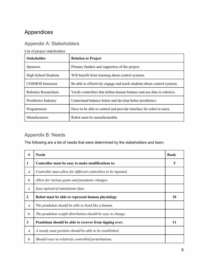
Appendix A: Stakeholders List of project stakeholders
Stakeholder Relation to Project
Sponsors Primary funders and supporters of the project.
High School Students Will benefit from learning about control systems.
COSMOS Instructor Be able to effectively engage and teach students about control systems.
Robotics Researchers Verify controllers that define human balance and use data in robotics.
Prosthetics Industry Understand balance better and develop better prosthetics.
Programmers Have to be able to control and provide interface for robot to users.
Manufacturers Robot must be manufacturable.
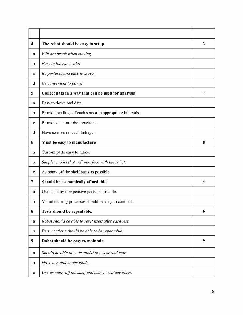
Appendix B: Needs The following are a list of needs that were determined by the stakeholders and team.
# Needs Rank
1 Controller must be easy to make modifications to. 5
a Controller must allow for different controllers to be inputted.
b Allow for various gains and parameter changes.
c Easy upload of simulations data.
2 Robot must be able to represent human physiology 10
a The pendulum should be able to bend like a human.
b The pendulum weight distribution should be easy to change.
3 Pendulum should be able to recover from tipping over. 11
a A steady state position should be able to be established.
b Should react to relatively controlled perturbations.
8
4 The robot should be easy to setup. 3
a Will not break when moving.
b Easy to interface with.
c Be portable and easy to move.
d Be convenient to power
5 Collect data in a way that can be used for analysis 7
a Easy to download data.
b Provide readings of each sensor in appropriate intervals.
c Provide data on robot reactions.
d Have sensors on each linkage.
6 Must be easy to manufacture 8
a Custom parts easy to make.
b Simpler model that will interface with the robot.
c As many off the shelf parts as possible.
7 Should be economically affordable 4
a Use as many inexpensive parts as possible.
b Manufacturing processes should be easy to conduct.
8 Tests should be repeatable. 6
a Robot should be able to reset itself after each test.
b Perturbations should be able to be repeatable.
9 Robot should be easy to maintain 9
a Should be able to withstand daily wear and tear.
b Have a maintenance guide.
c Use as many off the shelf and easy to replace parts.
9
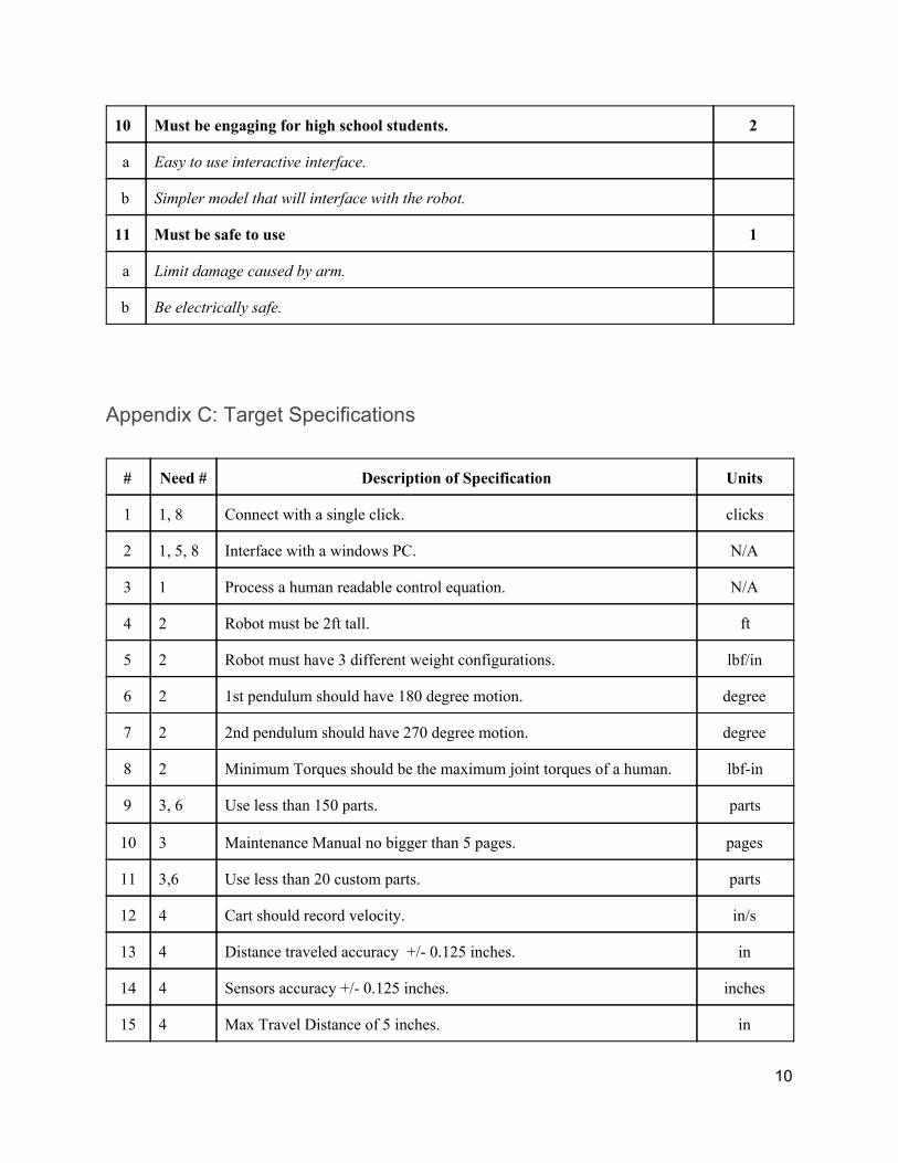
10 Must be engaging for high school students. 2
a Easy to use interactive interface.
b Simpler model that will interface with the robot.
11 Must be safe to use 1
a Limit damage caused by arm.
b Be electrically safe.
Appendix C: Target Specifications
# Need # Description of Specification Units
1 1, 8 Connect with a single click. clicks
2 1, 5, 8 Interface with a windows PC. N/A
3 1 Process a human readable control equation. N/A
4 2 Robot must be 2ft tall. ft
5 2 Robot must have 3 different weight configurations. lbf/in
6 2 1st pendulum should have 180 degree motion. degree
7 2 2nd pendulum should have 270 degree motion. degree
8 2 Minimum Torques should be the maximum joint torques of a human. lbf-in
9 3, 6 Use less than 150 parts. parts
10 3 Maintenance Manual no bigger than 5 pages. pages
11 3,6 Use less than 20 custom parts. parts
12 4 Cart should record velocity. in/s
13 4 Distance traveled accuracy +/- 0.125 inches. in
14 4 Sensors accuracy +/- 0.125 inches. inches
15 4 Max Travel Distance of 5 inches. in
10
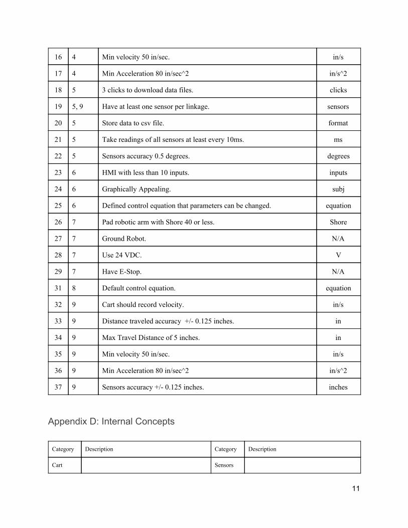
16 4 Min velocity 50 in/sec. in/s
17 4 Min Acceleration 80 in/sec^2 in/s^2
18 5 3 clicks to download data files. clicks
19 5, 9 Have at least one sensor per linkage. sensors
20 5 Store data to csv file. format
21 5 Take readings of all sensors at least every 10ms. ms
22 5 Sensors accuracy 0.5 degrees. degrees
23 6 HMI with less than 10 inputs. inputs
24 6 Graphically Appealing. subj
25 6 Defined control equation that parameters can be changed. equation
26 7 Pad robotic arm with Shore 40 or less. Shore
27 7 Ground Robot. N/A
28 7 Use 24 VDC. V
29 7 Have E-Stop. N/A
31 8 Default control equation. equation
32 9 Cart should record velocity. in/s
33 9 Distance traveled accuracy +/- 0.125 inches. in
34 9 Max Travel Distance of 5 inches. in
35 9 Min velocity 50 in/sec. in/s
36 9 Min Acceleration 80 in/sec^2 in/s^2
37 9 Sensors accuracy +/- 0.125 inches. inches
Appendix D: Internal Concepts
Category Description Category Description
Cart Sensors
11
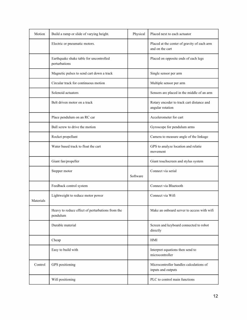
Motion Build a ramp or slide of varying height. Physical Placed next to each actuator
Electric or pneumatic motors. Placed at the center of gravity of each arm and on the cart
Earthquake shake table for uncontrolled perturbations
Placed on opposite ends of each legs
Magnetic pulses to send cart down a track Single sensor per arm
Circular track for continuous motion Multiple sensor per arm
Solenoid actuators Sensors are placed in the middle of an arm
Belt driven motor on a track Rotary encoder to track cart distance and angular rotation
Place pendulum on an RC car Accelerometer for cart
Ball screw to drive the motion Gyroscope for pendulum arms
Rocket propellant Camera to measure angle of the linkage
Water based track to float the cart GPS to analyze location and relatie movement
Giant fan/propeller Giant touchscreen and stylus system
Stepper motor Software
Connect via serial
Feedback control system Connect via Bluetooth
Materials
Lightweight to reduce motor power Connect via Wifi
Heavy to reduce effect of perturbations from the pendulum
Make an onboard server to access with wifi
Durable material Screen and keyboard connected to robot directly
Cheap HMI
Easy to build with Interpret equations then send to microcontroller
Control GPS positioning Microcontroller handles calculations of inputs and outputs
Wifi positioning PLC to control main functions
12
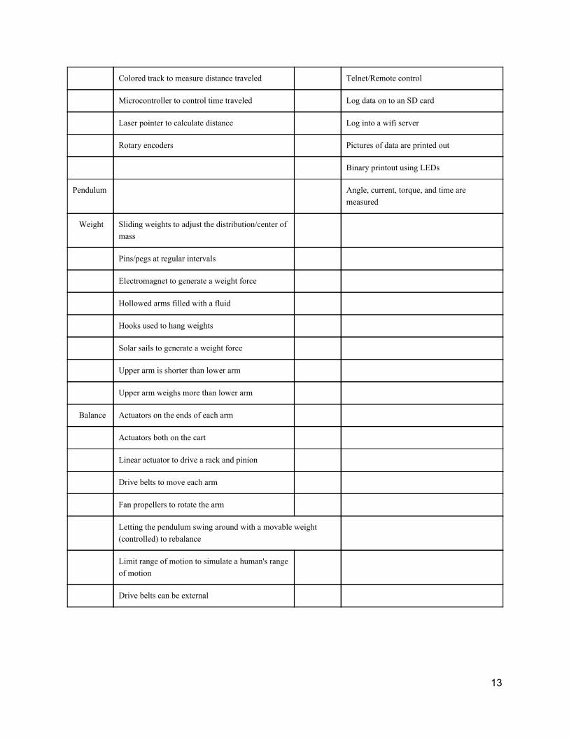
Colored track to measure distance traveled Telnet/Remote control
Microcontroller to control time traveled Log data on to an SD card
Laser pointer to calculate distance Log into a wifi server
Rotary encoders Pictures of data are printed out
Binary printout using LEDs
Pendulum Angle, current, torque, and time are measured
Weight Sliding weights to adjust the distribution/center of mass
Pins/pegs at regular intervals
Electromagnet to generate a weight force
Hollowed arms filled with a fluid
Hooks used to hang weights
Solar sails to generate a weight force
Upper arm is shorter than lower arm
Upper arm weighs more than lower arm
Balance Actuators on the ends of each arm
Actuators both on the cart
Linear actuator to drive a rack and pinion
Drive belts to move each arm
Fan propellers to rotate the arm
Letting the pendulum swing around with a movable weight (controlled) to rebalance
Limit range of motion to simulate a human's range of motion
Drive belts can be external
13
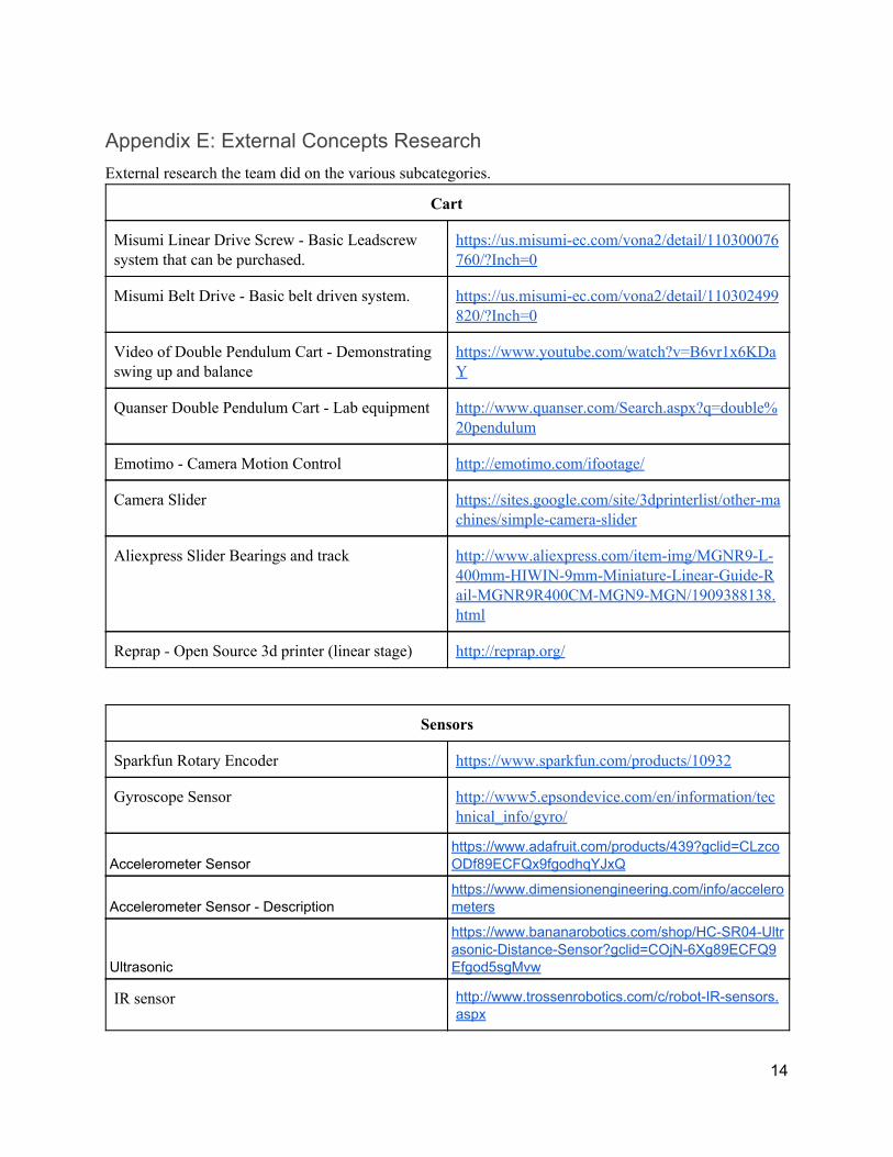
Appendix E: External Concepts Research External research the team did on the various subcategories.
Cart
Misumi Linear Drive Screw - Basic Leadscrew system that can be purchased.
https://us.misumi-ec.com/vona2/detail/110300076760/?Inch=0
Misumi Belt Drive - Basic belt driven system. https://us.misumi-ec.com/vona2/detail/110302499820/?Inch=0
Video of Double Pendulum Cart - Demonstrating swing up and balance
https://www.youtube.com/watch?v=B6vr1x6KDaY
Quanser Double Pendulum Cart - Lab equipment http://www.quanser.com/Search.aspx?q=double%20pendulum
Emotimo - Camera Motion Control http://emotimo.com/ifootage/
Camera Slider https://sites.google.com/site/3dprinterlist/other-machines/simple-camera-slider
Aliexpress Slider Bearings and track http://www.aliexpress.com/item-img/MGNR9-L-400mm-HIWIN-9mm-Miniature-Linear-Guide-Rail-MGNR9R400CM-MGN9-MGN/1909388138.html
Reprap - Open Source 3d printer (linear stage) http://reprap.org/
Sensors
Sparkfun Rotary Encoder https://www.sparkfun.com/products/10932
Gyroscope Sensor http://www5.epsondevice.com/en/information/technical_info/gyro/
Accelerometer Sensor https://www.adafruit.com/products/439?gclid=CLzcoODf89ECFQx9fgodhqYJxQ
Accelerometer Sensor - Description https://www.dimensionengineering.com/info/accelerometers
Ultrasonic
https://www.bananarobotics.com/shop/HC-SR04-Ultrasonic-Distance-Sensor?gclid=COjN-6Xg89ECFQ9Efgod5sgMvw
IR sensor http://www.trossenrobotics.com/c/robot-IR-sensors.aspx
14

Actuators
Stepper Motor https://en.wikipedia.org/wiki/Stepper_motor
Brushless DC Motor https://en.wikipedia.org/wiki/Brushless_DC_electric_motor
Hydraulic Rotary Actuator http://ph.parker.com/us/en/hydraulic-rotary-actuators
Drive Belts http://sdp-si.com/products/timing-belts/gt2.php
Pneumatic rotary actuator http://ph.parker.com/us/en/pneumatic-rotary-actuator-prn-series-vane
SMC rotary pneumatic actuator http://www.smcetech.com/CC_host/pages/custom/templates/smc_v2/prodtree_branch_group_2.cfm?cc_nvl=((CC,smc,ACT_US,Node_20136))&CFID=14844630&CFTOKEN=48021297&jsessionid=84304c83f0811ff741e62b567e16251c732c
DC Motor Stall Torque http://lancet.mit.edu/motors/motors3.html
DC Motor Torque http://fab.cba.mit.edu/classes/961.04/topics/speed_torquecurve.pdf
Pneumatic Artificial Muscles https://en.wikipedia.org/wiki/Pneumatic_artificial_muscles
Double Pendulum
Double Pendulum demonstration using single actuator
http://www.pendcon.de/double-pendulum.html
Double pendulum - Research of chaotic behavior of double pendulum.
http://www.noise.physx.u-szeged.hu/Research/DoublePendulum/
US Patent - Drive system for multiple axis robot arm
https://www.google.com/patents/US6601468
US Patent- Methods and systems for double-pendulum crane control
https://www.google.com/patents/US8235229
Double Pendulum - CAD Model https://grabcad.com/library/double-pendulum?locale=ru
15
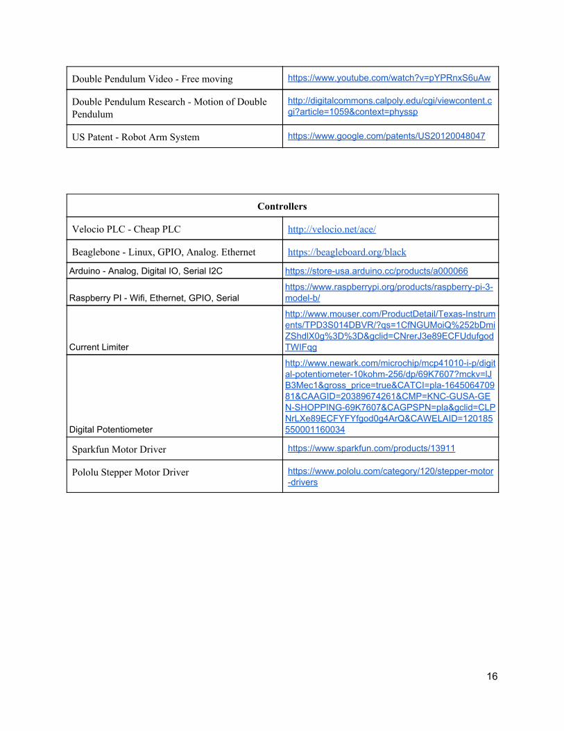
Double Pendulum Video - Free moving https://www.youtube.com/watch?v=pYPRnxS6uAw
Double Pendulum Research - Motion of Double Pendulum
http://digitalcommons.calpoly.edu/cgi/viewcontent.cgi?article=1059&context=physsp
US Patent - Robot Arm System https://www.google.com/patents/US20120048047
Controllers
Velocio PLC - Cheap PLC http://velocio.net/ace/
Beaglebone - Linux, GPIO, Analog. Ethernet https://beagleboard.org/black
Arduino - Analog, Digital IO, Serial I2C https://store-usa.arduino.cc/products/a000066
Raspberry PI - Wifi, Ethernet, GPIO, Serial https://www.raspberrypi.org/products/raspberry-pi-3-model-b/
Current Limiter
http://www.mouser.com/ProductDetail/Texas-Instruments/TPD3S014DBVR/?qs=1CfNGUMoiQ%252bDmiZShdlX0g%3D%3D&gclid=CNrerJ3e89ECFUdufgodTWIFqg
Digital Potentiometer
http://www.newark.com/microchip/mcp41010-i-p/digital-potentiometer-10kohm-256/dp/69K7607?mckv=lJB3Mec1&gross_price=true&CATCI=pla-164506470981&CAAGID=20389674261&CMP=KNC-GUSA-GEN-SHOPPING-69K7607&CAGPSPN=pla&gclid=CLPNrLXe89ECFYFYfgod0g4ArQ&CAWELAID=120185550001160034
Sparkfun Motor Driver https://www.sparkfun.com/products/13911
Pololu Stepper Motor Driver https://www.pololu.com/category/120/stepper-motor-drivers
16
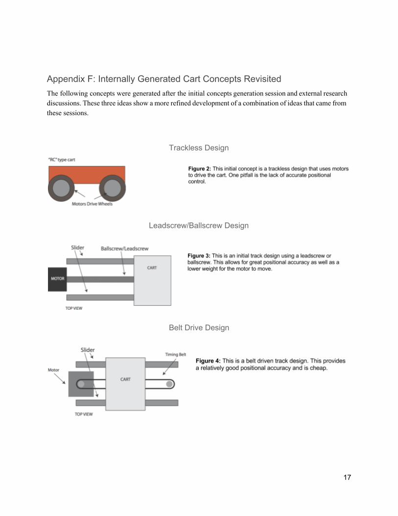
Appendix F: Internally Generated Cart Concepts Revisited The following concepts were generated after the initial concepts generation session and external research discussions. These three ideas show a more refined development of a combination of ideas that came from these sessions.
Trackless Design
Leadscrew/Ballscrew Design
Belt Drive Design
17
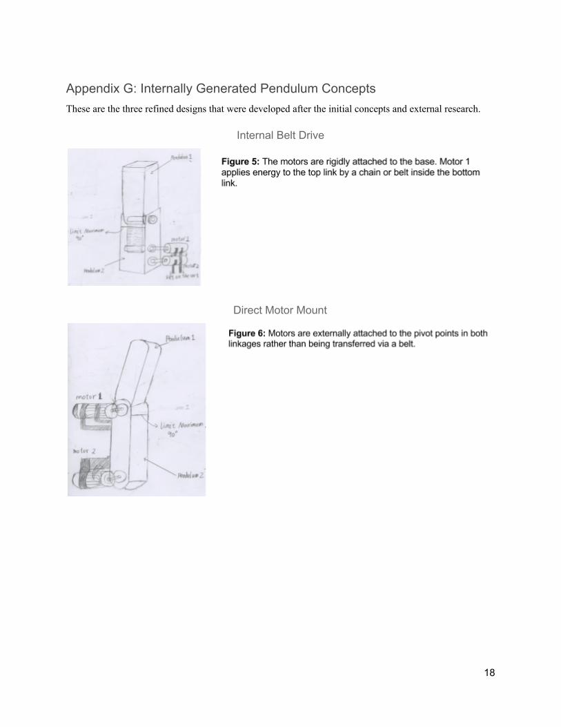
Appendix G: Internally Generated Pendulum Concepts These are the three refined designs that were developed after the initial concepts and external research.
Internal Belt Drive
Direct Motor Mount
18
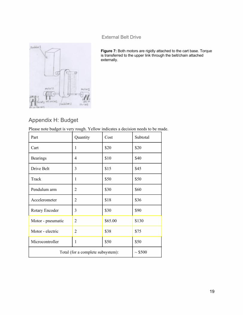
External Belt Drive
Appendix H: Budget Please note budget is very rough. Yellow indicates a decision needs to be made.
Part Quantity Cost Subtotal
Cart 1 $20 $20
Bearings 4 $10 $40
Drive Belt 3 $15 $45
Track 1 $50 $50
Pendulum arm 2 $30 $60
Accelerometer 2 $18 $36
Rotary Encoder 3 $30 $90
Motor - pneumatic 2 $65.00 $130
Motor - electric 2 $38 $75
Microcontroller 1 $50 $50
Total (for a complete subsystem): ~ $500
19

Appendix I: Gantt Chart
Figure 8. Complete Gantt chart for weeks 1 through 20. (Legend: green - completed tasks, red -
late tasks, blue - upcoming tasks)
20