Embed Size (px)
Citation preview

CONTROLSA Division of BRAY INTERNATIONAL, Inc.
TM-1056 Pneumatic Actuator - 08/13/2010
Technical Manual
Bray Pneumatic Actuators & Accessories
All statements, technical information, and recommendations in this bulletin are for general use only. Consult Bray representatives or factory for the specific requirements and material selection for your intended application. The right to change or modify product design or product without prior notice is reserved.
Bray Pneumatic Actuators & AccessoriesTechnical Manual - Table of Contents
Topic Page(s)
Actuator
Installation Notes ............................................................. 3
Mounting Codes ............................................................... 3
Pneumatic Actuator Data.................................................. 4
Series 92 Torque Data ....................................................... 5
Series 93 Torque Data (Imperial) ....................................... 6
Series 93 Torque Data (Metric) ......................................... 7
Proximity Switch
Series 52 Proximity Switch Models ................................... 8
Series 52 Proximity Switch and Display Dimensions ......... 9
Series 52 Specifications ................................................... 10
Series 50 Switch Options ................................................. 11
Positioner
Series 64 Positioner ......................................................... 12
Operators
Series 05 Declutchable Gear Operator ............................. 13

All information herein is proprietary and confidential and may not be copied or reproduced without the expressed written consent of BRAY INTERNATIONAL, Inc.The technical data herein is for general information only. Product suitability should be based solely upon customer’s detailed knowledge and experience with their application.
Pneumatic Actuator & Accessories
Installation : 3 All information herein is proprietary and confidential and may not be copied or reproduced without the expressed written consent of BRAY INTERNATIONAL, Inc.The technical data herein is for general information only. Product suitability should be based solely upon customer’s detailed knowledge and experience with their application.
Pneumatic Actuator & Accessories
Installation : 3
Actuator Installation NotesThese notes apply to the installation of Bray S92/93 pneumatic valve actuators.
• Verify that the valve and the actuator are both in the same position (both open or both closed) before mounting the actuator to the valve.
• Apply a light coating of grease to the inside of the actuator output bore before installing the actuator on the valve. This will allow the actuator to be more easily removed from the valve stem even after years of service.
• If stem adapters are required to match the actuator output bore to the valve stem, apply a light coating of grease to the inside of the stem adapter as well as the inside of the actuator output bore.
• Some stem adapters are kits consisting of multiple components. These kits may contain spacers that look like stem adapters, but are designed to keep the stem adapter in place during operation of the actuator. Verify that all stem adapters and spacers are installed in the proper position and sequence.
• If keyed stem adapters are used, the key must be held in the keyway so that it will not work loose during operation of the actuator. The key may be retained by any one of several methods: If the valve stem height matches the depth of the actuator output bore, use a key that fits the full length of the keyway. Tack weld the key to the adapter before installation in the actuator. Upset the end of the keyway after the key has been installed in the shaft by using a punch or chisel.
• If mounting studs are used instead of bolts, thread the studs completely into the actuator before placing the actuator on the valve. This assures that the full strength of the connection is achieved.
• While the mounting bolts are only finger tight, cycle the actuator fully open and fully closed to verify proper alignment on the valve.
• Tighten the mounting bolts or nuts in a diagonal pattern to evenly distribute stress in the bolts.
Actuator Mounting Codes for S92/93 - Imperial (In)
Actuator Sizes
Valve Code
Inner Bolt Circle Outer Bolt Circle Stem HoleBolt Circle (+/- .005)
No. Holes
Bolt SizeBolt Circle (+/- .005)
No. Holes
Bolt SizeBore
Diameter (+/- .004)
Across Flats
(+ .002-.0)Depth
Keyway Width (+ .002-.0)
48 AA 1.42 4 #10-32 1.97 4 1/4-20 0.4 0.32 1.3 NA63 A 1.969 4 1/4-20 2.756 4 5/16-18 0.552 0.395 1.38 NA83 C 1.969 4 1/4-20 2.756 4 5/16-18 0.749 0.513 1.46 NA93 C 1.969 4 1/4-20 2.756 4 5/16-18 0.749 0.513 1.46 NA
119 E 2.756 4 5/16-18 4.921 4 1/2-13 1.182 0.867 2.2 NA128 E 2.756 4 5/16-18 4.921 4 1/2-13 1.182 0.867 2.2 NA
160A E NA NA NA 4.921 4 1/2-13 1.182 0.867 2.2 NA160B F NA NA NA 4.921 4 1/2-13 1.38 NA 2.38 0.394210 G 4.921 4 1/2-13 6.496 4 5/8-11 1.97 NA 2.76 0.472
255A H 6.496 4 5/8-11 4.724 X 7.874 4 5/8-11 2.505 NA 4.25 0.625255B K 6.496 4 5/8-11 4.724 X 7.874 4 5/8-11 3.006 NA 4.25 0.750
Actuator Mounting Codes for S92/93 - Metric (mm)Actuator
SizesValve Code
Inner Bolt Circle Outer Bolt Circle Stem HoleBolt Circle (+/- .127)
No. Holes
Bolt SizeBolt Circle (+/- .127)
No. Holes
Bolt SizeBore Dia.(+/-.102)
Across Flats (+ .050-.0)
DepthKeyway Width
48 AA 36 4 M5 x 0.8P 50 4 M6 x 1.0P 10 8 33 NA63 A 50 4 M6 x 1.0P 70 4 M8 x 1.25P 14 10 35 NA83 C 50 4 M6 x 1.0P 70 4 M8 x 1.25P 19 13 37 NA93 C 50 4 M6 x 1.0P 70 4 M8 x 1.25P 19 13 37 NA119 E 70 4 M8 x 1.25P 125 4 M12 x 1.75P 30 22 56 NA128 E 70 4 M8 x 1.25P 125 4 M12 x 1.75P 30 22 56 NA
160A E NA NA NA 125 4 M12 x 1.75P 30 22 56 NA160B F NA NA NA 125 4 M12 x 1.75P 35 NA 60 10210 G 125 4 M12 x 1.75-6H 165 4 M16 x 2 - 6H 50 NA 70 12
255A H 165 4 M16 x 2 - 6H 120 x 200 4 M16 x 2 - 6H 64 NA 108 16255B K 165 4 M16 x 2 - 6H 120 x 200 4 M16 x 2 - 6H 76 NA 108 19

All information herein is proprietary and confidential and may not be copied or reproduced without the expressed written consent of BRAY INTERNATIONAL, Inc.The technical data herein is for general information only. Product suitability should be based solely upon customer’s detailed knowledge and experience with their application.
Pneumatic Actuator & Accessories
Data : 4 All information herein is proprietary and confidential and may not be copied or reproduced without the expressed written consent of BRAY INTERNATIONAL, Inc.The technical data herein is for general information only. Product suitability should be based solely upon customer’s detailed knowledge and experience with their application.
Pneumatic Actuator & Accessories
Data : 4
Pneumatic Actuator Data (Imperial)Actuator Speeds (Seconds)
Size 48 63 83 93 119 128 160 210 25590° Travel 1/4 1/4 1/4 1/4 1/2 1/2 1 2 2 3/4
Note: Times shown are in seconds at 80 PSIG supply pressure with 6ft. tubing having an internal diameter of approximately 1/4”. Bray S92/93 actuation times are very dependent on the flow capacity of their air supply. The use of smaller port solenoids, solenoid manifolds, smaller I.D. air supply tubing and/or extended lengths of tubing can significantly reduce the actuation time and/or initial response to the command signal.
Actuator Weights (lbs)Size 48 63 83 93 119 128 160 210 255
Double Acting 2.0 3.3 6.3 8.5 18.0 21.5 39.0 78.0 143.5
Spring Return 2.3 3.9 8.1 10.9 23.4 28.1 53.4 111.0 214.9
Weights are in lbs. Spring Return unit weights are with full set of springs on each piston.
Actuator Volumes (in3)Size 48 63 83 93 119 128 160 210 255
Counter-Clockwise 5.7 9.6 24.8 39.0 81.0 106.5 187.5 360.0 750.0
Clockwise 4.8 13.4 32.6 50.1 102.7 140.6 259.6 450.0 900.0
Counter-clockwise: Air volume in cubic inches required to push pistons apart, full travel.Clockwise: Air volume in cubic inches required to push pistons together, full travel.
Pneumatic Actuator Data (Metric)Actuator Speeds (Seconds)
Size 48 63 83 93 119 128 160 210 25590° Travel 1/4 1/4 1/4 1/4 1/2 1/2 1 2 2 3/4
Note: Times shown are in seconds at 5.5 bar supply pressure with 1.8 meter tubing having an internal diameter of approximately (6.35 mm). Bray S92/93 actuation times are very dependent on the flow capacity of their air supply. The use of smaller port solenoids, solenoid manifolds, smaller I.D. air supply tubing and/or extended lengths of tubing can significantly reduce the actuation time and/or initial response to the command signal.
Actuator Weights (kg)Size 48 63 83 93 119 128 160 210 255
Double Acting 0.9 1.5 2.9 3.9 8.2 9.8 17.7 35.4 65.1
Spring Return 1.0 1.8 3.7 4.9 10.6 12.7 24.2 50.3 115.7
Weights are in kg Spring Return unit weights are with full set of springs on each piston.
Actuator Volumes (cm3)Size 48 63 83 93 119 128 160 210 255
Counter-Clockwise 93.4 157.3 406.4 638.6 1327.5 1744.5 3072.6 5899.3 12290.3
Clockwise 78.7 219.6 534.2 820.5 1683.1 2303.3 4254.1 7374.2 14748.4
Counter-clockwise: Air volume in cubic millimeters required to push pistons apart, full travel.Clockwise: Air volume in cubic millimeters required to push pistons together, full travel.

All information herein is proprietary and confidential and may not be copied or reproduced without the expressed written consent of BRAY INTERNATIONAL, Inc.The technical data herein is for general information only. Product suitability should be based solely upon customer’s detailed knowledge and experience with their application.
Pneumatic Actuator & Accessories
Torque : 5 All information herein is proprietary and confidential and may not be copied or reproduced without the expressed written consent of BRAY INTERNATIONAL, Inc.The technical data herein is for general information only. Product suitability should be based solely upon customer’s detailed knowledge and experience with their application.
Pneumatic Actuator & Accessories
Torque : 5
ActuatorSize
Air Supply Pressure (PSIG)40 60 80 100 120
48 75 113 150 188 22563 145 221 297 373 44983 351 536 721 906 109193 493 753 1013 1272 1532119 1058 1615 2171 2728 3285128 1410 2152 2894 3636 4378160 2797 4270 5742 7214 8687210 5783 8826 11870 14914 17957255 14211 21691 29171 36650 44130
Series 92 Actuator Torque Data (Lb-in) Double Acting Pneumatic Operated, Torque Output
ActuatorSize
Air Supply Pressure (Bar)2.8 4.1 5.5 6.9 8.3
48 9 13 17 21 2563 16 25 34 42 5183 40 61 82 102 12393 56 85 115 144 173119 120 183 245 308 371128 159 243 327 411 495160 316 482 649 815 982210 653 997 1341 1685 2029255 1606 2451 3296 4141 4986
Series 92 Actuator Torque Data (N-m) Double Acting Pneumatic Operated, Torque Output
Series 92 Torque Data
All information herein is proprietary and confidential and may not be copied or reproduced without the expressed written consent of BRAY INTERNATIONAL, Inc.The technical data herein is for general information only. Product suitability should be based solely upon customer’s detailed knowledge and experience with their application.
Pneumatic Actuator & Accessories
Torque : 6 All information herein is proprietary and confidential and may not be copied or reproduced without the expressed written consent of BRAY INTERNATIONAL, Inc.The technical data herein is for general information only. Product suitability should be based solely upon customer’s detailed knowledge and experience with their application.
Pneumatic Actuator & Accessories
Torque : 6
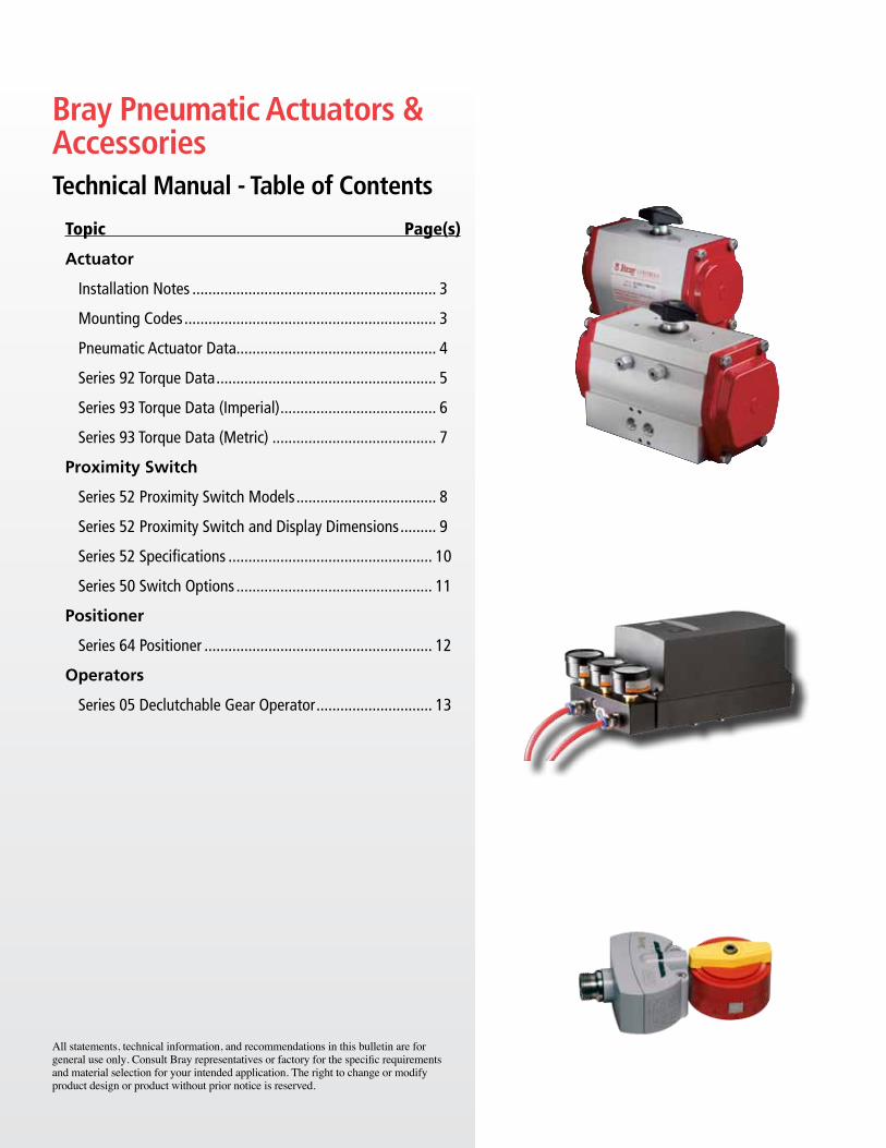
Series 93 Actuator Torque Data (Lb-In) Air Operated, With Spring Return, Torque Output
ActuatorSize
No.Springs
perPiston
Air Supply Pressure (PSIG) Spring40 60 80 100 120 Spring
StartStroke
EndStart End Start End Start End Start End Start End
48
1 51 32 89 70 126 107 164 145 201 182 43 242/1 39 10 77 48 114 85 152 123 189 160 65 362 64 27 101 64 139 102 176 139 86 49
3/2 52 5 89 42 127 80 164 117 108 613 77 21 115 59 152 96 129 73
63
2 91 65 167 141 243 217 319 293 395 369 80 543 64 27 140 103 216 179 292 255 368 331 118 814 113 65 189 141 265 217 341 293 156 1085 86 27 162 103 238 179 314 255 194 1356 135 65 211 141 287 217 232 162
83
2 210 167 395 352 580 537 765 722 950 907 184 1413 156 76 341 261 526 446 711 631 896 816 275 1954 281 176 466 361 651 546 836 731 360 2555 220 97 405 282 590 467 775 652 439 3166 369 185 554 370 739 555 536 352
93
2 310 232 570 492 830 752 1089 1011 1349 1271 261 1833 218 101 478 361 738 621 997 880 1257 1140 392 2754 386 231 646 491 905 750 1165 1010 522 3675 294 94 554 354 813 613 1073 873 659 4596 462 229 721 488 981 748 784 551
119
2 692 469 1249 1026 1805 1582 2362 2139 2919 2696 589 3663 509 174 1066 731 1622 1287 2179 1844 2736 2401 884 5494 883 437 1439 993 1996 1550 2553 2107 1178 7325 700 142 1256 698 1813 1255 2370 1812 1473 9156 1073 404 1630 961 2187 1518 1767 1098
128
2 880 465 1622 1207 2364 1949 3106 2691 3848 3433 945 5303 1357 733 2099 1475 2841 2217 3583 2959 1419 7954 1094 261 1836 1003 2578 1745 3320 2487 1891 10585 1568 529 2310 1271 3052 2013 2365 13266 1302 57 2044 799 2786 1541 2837 1592
160
2 1819 1118 3292 2591 4764 4063 6236 5535 7709 7008 1679 9783 1399 349 2872 1822 4344 3294 5816 4766 7289 6239 2448 13984 2452 1123 3924 2595 5396 4067 6869 5540 3147 18185 2030 353 3502 1825 4974 3297 6447 4770 3917 22406 3154 1196 4626 2668 6099 4141 4546 2588
210
2 3833 2508 6876 5551 9920 8595 12964 11639 16007 14682 3275 19503 2859 868 5902 3911 8946 6955 11990 9999 15033 13042 4915 29244 4930 2275 7974 5319 11018 8363 14061 11406 6551 38965 3949 638 6993 3682 10037 6726 13080 9769 8188 48776 6022 2031 9066 5075 12109 8118 9839 5848
255
2 9487 6747 16967 14227 24447 21707 31926 29186 39406 36666 7464 47243 7125 3015 14605 10495 22085 17975 29564 25454 37044 32934 11196 70864 12243 6762 19723 14242 27202 21721 34682 29201 14929 94485 9880 3030 17360 10510 24839 17989 32319 25469 18661 118116 14998 6778 22477 14257 29957 21737 22393 14173

All information herein is proprietary and confidential and may not be copied or reproduced without the expressed written consent of BRAY INTERNATIONAL, Inc.The technical data herein is for general information only. Product suitability should be based solely upon customer’s detailed knowledge and experience with their application.
Pneumatic Actuator & Accessories
Torque : 7 All information herein is proprietary and confidential and may not be copied or reproduced without the expressed written consent of BRAY INTERNATIONAL, Inc.The technical data herein is for general information only. Product suitability should be based solely upon customer’s detailed knowledge and experience with their application.
Pneumatic Actuator & Accessories
Torque : 7
Series 93 Actuator Torque Data (N-m) Air Operated, With Spring Return, Torque Output
ActuatorSize
No.Springs
perPiston
Air Supply Pressure (Bar) Spring2.8 4.1 5.5 6.9 8.3 Spring
StartStroke
EndStart End Start End Start End Start End Start End
48
1 6 4 10 8 14 12 19 16 23 21 5 32/1 4 1 9 5 13 10 17 14 21 18 7 42 7 3 11 7 16 12 20 16 10 6
3/2 6 1 10 5 14 9 19 13 12 73 9 2 13 7 17 11 15 8
63
2 10 7 19 16 28 25 36 33 45 42 9 63 7 3 16 12 24 20 33 29 42 37 13 94 13 7 21 16 30 25 39 33 18 125 10 3 18 12 27 20 36 29 22 156 15 7 24 16 32 25 26 18
83
2 24 19 45 40 66 61 86 82 107 103 21 163 18 9 39 30 59 50 80 71 101 92 31 224 32 20 53 41 74 62 95 83 41 295 25 11 46 32 67 53 88 74 50 366 42 21 63 42 84 63 61 40
93
2 35 26 64 56 94 85 123 114 152 144 30 213 25 11 54 41 83 70 113 99 142 129 44 314 44 26 73 56 102 85 132 114 59 425 33 11 63 40 92 69 121 99 75 526 52 26 82 55 111 85 89 62
119
2 78 53 141 116 204 179 267 242 330 305 67 413 58 20 120 83 183 145 246 208 309 271 100 624 100 49 163 112 226 175 289 238 133 835 79 16 142 79 205 142 268 205 166 1036 121 46 184 109 247 172 200 124
128
2 99 53 183 136 267 220 351 304 435 388 107 603 153 83 237 167 321 251 405 334 160 904 124 30 207 113 291 197 375 281 214 1205 177 60 261 144 345 227 267 1506 147 6 231 90 315 174 321 180
160
2 206 126 372 293 538 459 705 625 871 792 190 1113 158 39 325 206 491 372 657 539 824 705 277 1584 277 127 443 293 610 460 776 626 356 2055 229 40 396 206 562 373 728 539 443 2536 356 135 523 301 689 468 514 292
210
2 433 283 777 627 1121 971 1465 1315 1809 1659 370 2203 323 98 667 442 1011 786 1355 1130 1699 1474 555 3304 557 257 901 601 1245 945 1589 1289 740 4405 446 72 790 416 1134 760 1478 1104 925 5516 680 230 1024 573 1368 917 1112 661
255
2 1072 762 1917 1607 2762 2453 3607 3298 4452 4143 843 5343 805 341 1650 1186 2495 2031 3340 2876 4185 3721 1265 8014 1383 764 2228 1609 3073 2454 3919 3299 1687 10685 1116 342 1961 1188 2806 2033 3652 2878 2108 13356 1695 766 2540 1611 3385 2456 2530 1601
All information herein is proprietary and confidential and may not be copied or reproduced without the expressed written consent of BRAY INTERNATIONAL, Inc.The technical data herein is for general information only. Product suitability should be based solely upon customer’s detailed knowledge and experience with their application.
Pneumatic Actuator & Accessories
Proxsensor : 8 All information herein is proprietary and confidential and may not be copied or reproduced without the expressed written consent of BRAY INTERNATIONAL, Inc.The technical data herein is for general information only. Product suitability should be based solely upon customer’s detailed knowledge and experience with their application.
Pneumatic Actuator & Accessories
Proxsensor : 8
SolenoidCable
+–AS-i –
3
124
AS-i +SolenoidCable
+–AS-i –
AS-i +
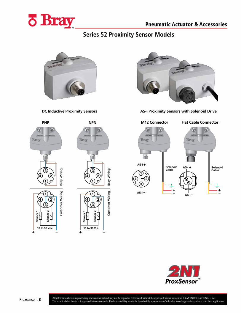
Series 52 Proximity Sensor Models
DC Inductive Proximity Sensors
M12 Connector Flat Cable Connector
1
324
3
124
Bra
y W
irin
gC
ust
om
er W
irin
g
+ –10 to 30 Vdc
NPN
Sens
or 2
Sens
or 1
1
324
3
124
Bra
y W
irin
gC
ust
om
er W
irin
g
PNP
+ –10 to 30 Vdc
Sens
or 2
Sens
or 1
AS-i Proximity Sensors with Solenoid Drive

All information herein is proprietary and confidential and may not be copied or reproduced without the expressed written consent of BRAY INTERNATIONAL, Inc.The technical data herein is for general information only. Product suitability should be based solely upon customer’s detailed knowledge and experience with their application.
Pneumatic Actuator & Accessories
Proxsensor : 9 All information herein is proprietary and confidential and may not be copied or reproduced without the expressed written consent of BRAY INTERNATIONAL, Inc.The technical data herein is for general information only. Product suitability should be based solely upon customer’s detailed knowledge and experience with their application.
Pneumatic Actuator & Accessories
Proxsensor : 9
AC Inductive Proximity Sensors DeviceNet Proximity Sensors with Solenoid Drive
PROFIBUS DP Proximity Sensors with Solenoid Drive
5
1
4
23
1
5
2
43
NC
NC
Bra
y W
irin
gC
ust
om
er W
irin
g
NeutralAC Live20 to 250 Vac
Sens
or 1
Sens
or 2
+ +
1
324
3
124
Bra
y W
irin
gC
ust
om
er W
irin
g
+ – Sens
or 2
Sens
or 1
– +
– –
NAMURIntrinsically Safe
1 52 43
V+ V- CAN-H CAN-L
SolenoidCable
+–
SolenoidIn
Terminal Strip Connections
PROFIBUS DPOut
PROFIBUS DPIn
V-
V+B
A
GND
SOL+
SOL-
NCX10
X1
Series 52 Proximity Sensor Models
All information herein is proprietary and confidential and may not be copied or reproduced without the expressed written consent of BRAY INTERNATIONAL, Inc.The technical data herein is for general information only. Product suitability should be based solely upon customer’s detailed knowledge and experience with their application.
Pneumatic Actuator & Accessories
Proxsensor : 10 All information herein is proprietary and confidential and may not be copied or reproduced without the expressed written consent of BRAY INTERNATIONAL, Inc.The technical data herein is for general information only. Product suitability should be based solely upon customer’s detailed knowledge and experience with their application.
Pneumatic Actuator & Accessories
Proxsensor : 10
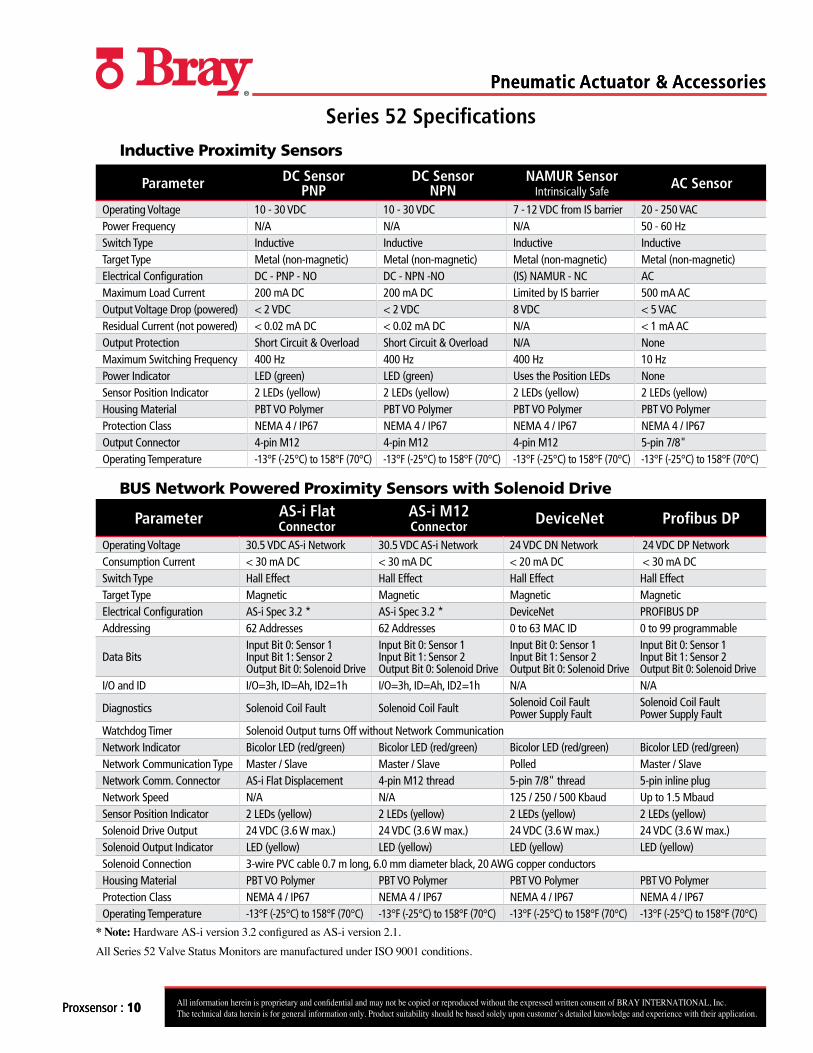
Series 52 Specifications
Inductive Proximity Sensors
Parameter DC Sensor PNP
DC Sensor NPN
NAMUR Sensor Intrinsically Safe
AC Sensor
Operating Voltage 10 - 30 VDC 10 - 30 VDC 7 - 12 VDC from IS barrier 20 - 250 VACPower Frequency N/A N/A N/A 50 - 60 HzSwitch Type Inductive Inductive Inductive InductiveTarget Type Metal (non-magnetic) Metal (non-magnetic) Metal (non-magnetic) Metal (non-magnetic)Electrical Configuration DC - PNP - NO DC - NPN -NO (IS) NAMUR - NC ACMaximum Load Current 200 mA DC 200 mA DC Limited by IS barrier 500 mA ACOutput Voltage Drop (powered) < 2 VDC < 2 VDC 8 VDC < 5 VACResidual Current (not powered) < 0.02 mA DC < 0.02 mA DC N/A < 1 mA ACOutput Protection Short Circuit & Overload Short Circuit & Overload N/A NoneMaximum Switching Frequency 400 Hz 400 Hz 400 Hz 10 HzPower Indicator LED (green) LED (green) Uses the Position LEDs NoneSensor Position Indicator 2 LEDs (yellow) 2 LEDs (yellow) 2 LEDs (yellow) 2 LEDs (yellow)Housing Material PBT VO Polymer PBT VO Polymer PBT VO Polymer PBT VO PolymerProtection Class NEMA 4 / IP67 NEMA 4 / IP67 NEMA 4 / IP67 NEMA 4 / IP67Output Connector 4-pin M12 4-pin M12 4-pin M12 5-pin 7/8"Operating Temperature -13°F (-25°C) to 158°F (70°C) -13°F (-25°C) to 158°F (70°C) -13°F (-25°C) to 158°F (70°C) -13°F (-25°C) to 158°F (70°C)
BUS Network Powered Proximity Sensors with Solenoid Drive
Parameter AS-i Flat Connector
AS-i M12 Connector DeviceNet Profibus DP
Operating Voltage 30.5 VDC AS-i Network 30.5 VDC AS-i Network 24 VDC DN Network 24 VDC DP NetworkConsumption Current < 30 mA DC < 30 mA DC < 20 mA DC < 30 mA DCSwitch Type Hall Effect Hall Effect Hall Effect Hall EffectTarget Type Magnetic Magnetic Magnetic MagneticElectrical Configuration AS-i Spec 3.2 * AS-i Spec 3.2 * DeviceNet PROFIBUS DP Addressing 62 Addresses 62 Addresses 0 to 63 MAC ID 0 to 99 programmable
Data BitsInput Bit 0: Sensor 1Input Bit 1: Sensor 2Output Bit 0: Solenoid Drive
Input Bit 0: Sensor 1Input Bit 1: Sensor 2Output Bit 0: Solenoid Drive
Input Bit 0: Sensor 1Input Bit 1: Sensor 2Output Bit 0: Solenoid Drive
Input Bit 0: Sensor 1Input Bit 1: Sensor 2Output Bit 0: Solenoid Drive
I/O and ID I/O=3h, ID=Ah, ID2=1h I/O=3h, ID=Ah, ID2=1h N/A N/A
Diagnostics Solenoid Coil Fault Solenoid Coil Fault Solenoid Coil FaultPower Supply Fault
Solenoid Coil Fault Power Supply Fault
Watchdog Timer Solenoid Output turns Off without Network CommunicationNetwork Indicator Bicolor LED (red/green) Bicolor LED (red/green) Bicolor LED (red/green) Bicolor LED (red/green) Network Communication Type Master / Slave Master / Slave Polled Master / SlaveNetwork Comm. Connector AS-i Flat Displacement 4-pin M12 thread 5-pin 7/8" thread 5-pin inline plugNetwork Speed N/A N/A 125 / 250 / 500 Kbaud Up to 1.5 MbaudSensor Position Indicator 2 LEDs (yellow) 2 LEDs (yellow) 2 LEDs (yellow) 2 LEDs (yellow)Solenoid Drive Output 24 VDC (3.6 W max.) 24 VDC (3.6 W max.) 24 VDC (3.6 W max.) 24 VDC (3.6 W max.)Solenoid Output Indicator LED (yellow) LED (yellow) LED (yellow) LED (yellow)Solenoid Connection 3-wire PVC cable 0.7 m long, 6.0 mm diameter black, 20 AWG copper conductorsHousing Material PBT VO Polymer PBT VO Polymer PBT VO Polymer PBT VO PolymerProtection Class NEMA 4 / IP67 NEMA 4 / IP67 NEMA 4 / IP67 NEMA 4 / IP67Operating Temperature -13°F (-25°C) to 158°F (70°C) -13°F (-25°C) to 158°F (70°C) -13°F (-25°C) to 158°F (70°C) -13°F (-25°C) to 158°F (70°C)
* Note: Hardware AS-i version 3.2 configured as AS-i version 2.1.
All Series 52 Valve Status Monitors are manufactured under ISO 9001 conditions.

All information herein is proprietary and confidential and may not be copied or reproduced without the expressed written consent of BRAY INTERNATIONAL, Inc.The technical data herein is for general information only. Product suitability should be based solely upon customer’s detailed knowledge and experience with their application.
Pneumatic Actuator & Accessories
Switch Options : 11
Series 50 Switch Options
MICRO SWITCHESEconomical switches with the highest
current ratings on the market.
Two V3 Type SPDT SWITCheS Contact material is fine silver.
Max. Rating: 10A-120/250VAC1/2A-125VDC
Max. Temperature: 176°F (80°C)
4 or more switches are available.
Two Type DPDT SWITCheS Contact material is fine silver.
Max. Rating: 10A-120/250VAC10A-24VDC
Max. Temperature: 158°F (70°C)
PROXIMITY SWITCHESSealed against explosive gases and liquids, these switches offer long,
trouble free life.
Two V3 Type N INDUCTIVe SWITCheS (Intrinsically Safe)
Supply Volts: 5-25VDC
Load Current: <1mA >3mA
Max. Temperature: 212°F (100°C)
Other types available, consult factory.
Two V3 Type e2 INDUCTIVe SWITCheSSupply Volts: 10-30VDC
PNP Type:Load Current: 100mA
Max Temperature: 212°F (100°C)
Other types available, consult factory.
PNEUMATIC SWITCHESFor hazardous locations. 2 switches are provided with 2 ports and vents.
Rating: 150 psi (10 bar)
Connections: 1/8” NPT (BSP)
Max. Temperature: 176°F (80°C)
POTENTIOMETER
For analog feedback of precise valve position, a potentiometer can be mounted within the Series 50–0700 housing.
The standard value is 10K ohms, and the standard power rating at 158°F(70°C) is 1 watt.REED SWITCHES
2 magnetic reed switches (hermetically sealed) are available upon request.
All information herein is proprietary and confidential and may not be copied or reproduced without the expressed written consent of BRAY INTERNATIONAL, Inc.The technical data herein is for general information only. Product suitability should be based solely upon customer’s detailed knowledge and experience with their application.
Pneumatic Actuator & Accessories
Series 64 : 12 All information herein is proprietary and confidential and may not be copied or reproduced without the expressed written consent of BRAY INTERNATIONAL, Inc.The technical data herein is for general information only. Product suitability should be based solely upon customer’s detailed knowledge and experience with their application.
Pneumatic Actuator & Accessories
Series 64 : 12
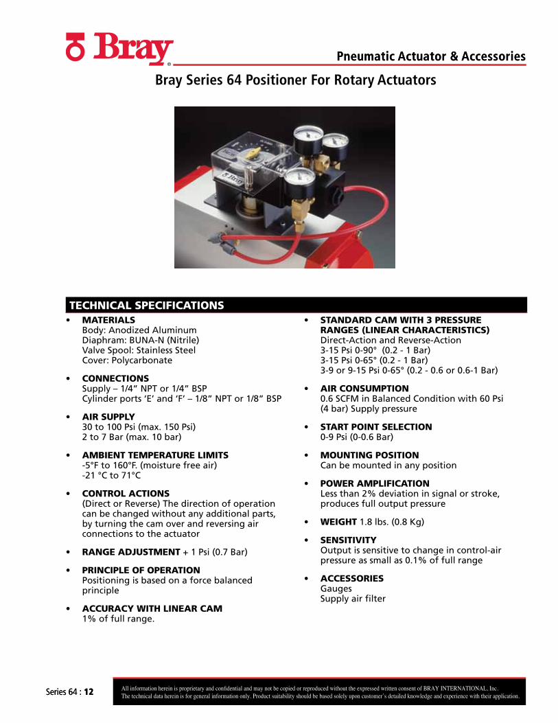
Bray Series 64 Positioner For Rotary Actuators
TECHNICAL SPECIFICATIONS• MATERIALS
Body: Anodized Aluminum Diaphram: BUNA-N (Nitrile) Valve Spool: Stainless Steel Cover: Polycarbonate
• CONNECTIONS Supply – 1/4” NPT or 1/4” BSP Cylinder ports ‘E’ and ‘F’ – 1/8” NPT or 1/8” BSP
• AIR SUPPLY 30 to 100 Psi (max. 150 Psi)2 to 7 Bar (max. 10 bar)
• AMBIENT TEMPERATURE LIMITS -5°F to 160°F. (moisture free air)-21 °C to 71°C
• CONTROL ACTIONS (Direct or Reverse) The direction of operation can be changed without any additional parts, by turning the cam over and reversing air connections to the actuator
• RANGE ADJUSTMENT + 1 Psi (0.7 Bar)
• PRINCIPLE OF OPERATION Positioning is based on a force balanced principle
• ACCURACY WITH LINEAR CAM 1% of full range.
• STANDARD CAM WITH 3 PRESSURE RANGES (LINEAR CHARACTERISTICS) Direct-Action and Reverse-Action 3-15 Psi 0-90° (0.2 - 1 Bar) 3-15 Psi 0-65° (0.2 - 1 Bar) 3-9 or 9-15 Psi 0-65° (0.2 - 0.6 or 0.6-1 Bar)
• AIR CONSUMPTION 0.6 SCFM in Balanced Condition with 60 Psi (4 bar) Supply pressure
• START POINT SELECTION 0-9 Psi (0-0.6 Bar)
• MOUNTING POSITION Can be mounted in any position
• POWER AMPLIFICATION Less than 2% deviation in signal or stroke, produces full output pressure
• WEIGHT 1.8 lbs. (0.8 Kg)
• SENSITIVITY Output is sensitive to change in control-air pressure as small as 0.1% of full range
• ACCESSORIES Gauges Supply air filter
All information herein is proprietary and confidential and may not be copied or reproduced without the expressed written consent of BRAY INTERNATIONAL, Inc.The technical data herein is for general information only. Product suitability should be based solely upon customer’s detailed knowledge and experience with their application.
Pneumatic Actuator & Accessories
Series 05 : 13
Specifications and Operation
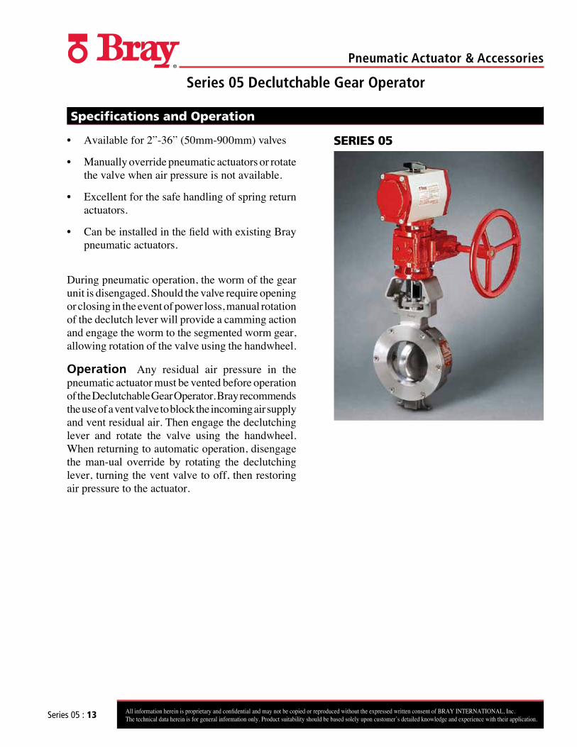
• Available for 2”-36” (50mm-900mm) valves
• Manually override pneumatic actuators or rotate the valve when air pressure is not available.
• Excellent for the safe handling of spring return actuators.
• Can be installed in the field with existing Bray pneumatic actuators.
During pneumatic operation, the worm of the gear unit is disengaged. Should the valve require opening or closing in the event of power loss, manual rotation of the declutch lever will provide a camming action and engage the worm to the segmented worm gear, allowing rotation of the valve using the handwheel.
Operation Any residual air pressure in the pneumatic actuator must be vented before operation of the Declutchable Gear Operator. Bray recommends the use of a vent valve to block the incoming air supply and vent residual air. Then engage the declutching lever and rotate the valve using the handwheel. When returning to automatic operation, disengage the man-ual override by rotating the declutching lever, turning the vent valve to off, then restoring air pressure to the actuator.
SERIES 05
Series 05 Declutchable Gear Operator