Embed Size (px)
Citation preview
A Distributed Camera System for Multi-Resolution
Surveillance
Nicola Bellotto∗, Eric Sommerlade∗, Ben Benfold∗, Charles Bibby∗, Ian Reid∗,
Daniel Roth†, Carles Fernandez‡, Luc Van Gool† and Jordi Gonzalez‡
∗Active Vision Laboratory, University of Oxford, United Kingdom
http://www.robots.ox.ac.uk/ActiveVision†Computer Vision Laboratory, ETH Zurich, Switzerland
Email: {droth,vangool}@vision.ee.ethz.ch‡Computer Vision Centre, Bellaterra, Spain
Email: {perno,poal}@cvc.uab.es
Abstract—We describe an architecture for a multi-camera,multi-resolution surveillance system. The aim is to support a setof distributed static and pan-tilt-zoom (PTZ) cameras and visualtracking algorithms, together with a central supervisor unit. Eachcamera (and possibly pan-tilt device) has a dedicated processand processor. Asynchronous interprocess communications andarchiving of data are achieved in a simple and effective way viaa central repository, implemented using an SQL database.
Visual tracking data from static views are stored dynamicallyinto tables in the database via client calls to the SQL server.A supervisor process running on the SQL server determines ifactive zoom cameras should be dispatched to observe a particulartarget, and this message is effected via writing demands intoanother database table.
We show results from a real implementation of the systemcomprising one static camera overviewing the environment underconsideration and a PTZ camera operating under closed-loopvelocity control, which uses a fast and robust level-set-basedregion tracker. Experiments demonstrate the effectiveness ofour approach and its feasibility to multi-camera systems forintelligent surveillance.
I. INTRODUCTION
We are motivated by the desire to develop cognitive visual
systems. In the context of surveillance, the theme of this paper,
by cognitive we mean a system which can not only track
targets, but identify them, and explain what is taking place,
especially taking account of any possible causal relationships.
This paper describes a system which we hope will support
work towards this goal. Here, we are primarily concerned with
the low-level data acquisition processes, how these processes
communicate, and also how any solution to these problems
could be used in the context of top-down processing. To this
end we describe an architecture for a multi-camera, multi-
resolution surveillance system. The proposed solutions and,
in particular, the use of a central SQL database provide a
reference application for the asynchronous communication
between visual processes, as well as an efficient way to store
large amounts of information for possible reasoning engines.
The system comprises a set of distributed static and PTZ
cameras and visual tracking algorithms, together with a central
supervisor unit. Each camera (and possibly pan-tilt device) has
a dedicated process and processor. Asynchronous interprocess
communications and archiving of data are achieved in a simple
and effective way via a central repository, implemented using
an SQL database. Visual tracking data from static views are
stored dynamically into tables in the database via client calls
to the SQL server. A supervisor process running on the SQL
server determines if active zoom cameras should be dispatched
to observe a particular target, and this message is effected via
writing demands into another database table.
We show initial results from a real implementation of the
system comprising a static and a PTZ camera, although the
system can be easily extended to include more devices thanks
to the modularity of our approach. The static camera runs
a figure/ground segmentation-based tracker, while the PTZ
camera operates under closed-loop velocity control using a
fast and robust level-set-based region tracker. The goal of the
system, as regulated by a supervisor process, is to keep track
of all targets in a scene using the overview camera, and to
acquire high-resolution, stabilised images of the faces of all
agents in the scene using zoom cameras in closed loop tracking
mode.
The remainder of the paper is organised as follows: in the
next section we review related work primarily considering
other systems which involve active cameras. In section III
we describe the overall system architecture, and specific
implementation details for each of the modules are considered
in section IV. We show preliminary results from an actual
implementation of the system in section V, and conclude with
a summary of our current and future research directions.
II. RELATED WORK
There has been a significant body of research published
on distributed multi-camera surveillance systems in recent
years. Since in this work we are concerned with a system that
supports active cameras – i.e. cameras which can zoom, pan
and tilt – the following review concentrates on other systems
employing similar devices.
By far the most common means to use active cameras is
in the context of a master–slave–configuration, in which a
set of dedicated, static supervisor cameras makes wide area
observations and coordinates control of the active sensing
parts [1], [2], [3]. A disadvantage of supervisor cameras is the
need for a mapping of image contents to the active camera,
which has to be obtained from restricted camera placements,
movements or temporally extended observations [4], [5], [6].
Methods exist which obtain an explicit calibration from
target movements [7], [8], or a mapping of world, or gaze
coordinates to gaze parameters of the slave. For this, [6] and
[2] use a single moving target, whereas [5] uses long term
observations. These efforts can be circumvented by restricted
camera placements [3], [4]. In contrast, systems without super-
visor cameras have to rely on heuristics to observe the scene
[9], [10].
Most of the systems above do not require the integration of
data from multiple sources into a common coordinate system.
In particular, positional data obtained by the active camera is
usually not fed back into the system, except for high resolution
image data obtained [6], [3], [1]. Similar to [2], [1], our system
is also fully calibrated, since we aim at integration of data from
all participating sensors in a single world coordinate system.
This strategy is akin to [2], but with higher degree of flexibility.
Whereas the active vision part uses a local controller strategy
close to their ”µSaccade”, the resulting data in our system is
fed back to the database. This includes higher layers for more
abstract reasoning, not only on the trajectory and visibility of
the single target under scrutiny.
For data exchange in multi camera systems, two common
aspects of system design – efficiency and modularity – need
to be balanced. The modularity aspect becomes inescapable
once the system is distributed among different machines.
Since active vision systems need shorter response times,
they often make use of less standardised methods, such as
sockets [11], or restrain themselves to multi-threaded appli-
cations on single machines [1], [4], [3]. A solution could be
XML [12] because of the human-readability and versatility of
this format. Unfortunately, the XML standard trades efficiency
for flexibility, thus it is seldom the first choice for active vision
systems. A promising alternative is modularisation based on
agents presented in [13], but the actual implementation of the
communication is unfortunately not touched.
A multi camera surveillance system that also proposes a
database for communication is presented in [14]. The authors
present a multi-camera surveillance system with over twenty
video cameras in a realistic, long-term setting. Real-time video
analysis (tracking and event detection) results are stored on-
line in a central database. The database supports parallel
inserts as well as queries to the data. However, no information
is given about the latency of the whole system.
III. SYSTEM ARCHITECTURE
Our aim is to develop a system comprising distributed
static and active cameras (with more or less overlapping fields
of view), supporting asynchronous real-time operations to
enhance the detection and tracking of targets. Our architecture
is based on a central supervising unit which communicates
with a set of semi-autonomous visual tracking processes.
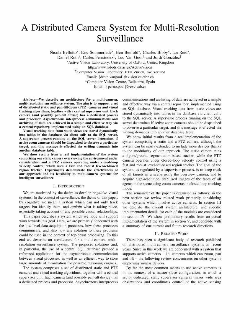
Fig. 1. System architecture.
Ultimately our objective for this supervisor process is to
assimilate tracking results from various cameras, deal with
assignments of cameras to targets, and to implement a layer
between low-level primarily data-driven processes, and higher-
level processes concerned with scene interpretation and repre-
sentation and learning of ontologies, etc.
In the present work, however, we are concerned only
with the supervisor, the data-driven, low-level processes, and
the means of communication. Interprocess communications
are mediated by the supervisor, and effected using an SQL
database. The database provides a natural means by which
messages can be passed between processes, in an architecture
independent fashion, simply by writing to and reading from
database tables/records, without the need to implement a
potentially complex asynchronous communications protocol.
It further provides an automatic means to archive data.
A schematic of the system is shown in Fig. 1. In summary,
the key components of our architecture are the following ones:
• Tracker with static camera (TSC), provided with a wide-
angle lens;
• Tracker with active camera (TAC), comprising a firewire
camera with integrated zoom lens (SONY DFW-VL500
and IMAGINGSOURCE DFK 21BF04-Z2) and a Di-
rected Perception DTU-D46 pan-tilt unit;
• Supervisor tracker module (SVT) dealing with data inte-
gration, command dispatch and high-level reasoning;
• SQL database shared by the above three components;
the present implementation comprises 4 tables: one for
observations/estimations generated by the trackers, one
for high-level commands sent by the SVT, another one
for stabilized images produced by the TAC, and finally
one to store calibration information for all the trackers.
Each tracker acts as an independent node with its own
processing unit connected to the systems via TCP/IP and
communicating by means of SQL queries. The SVT runs on
a linux-based machine with a MySQL server. All the units
are synchronized using the standard Network Time Protocol
(NTP).
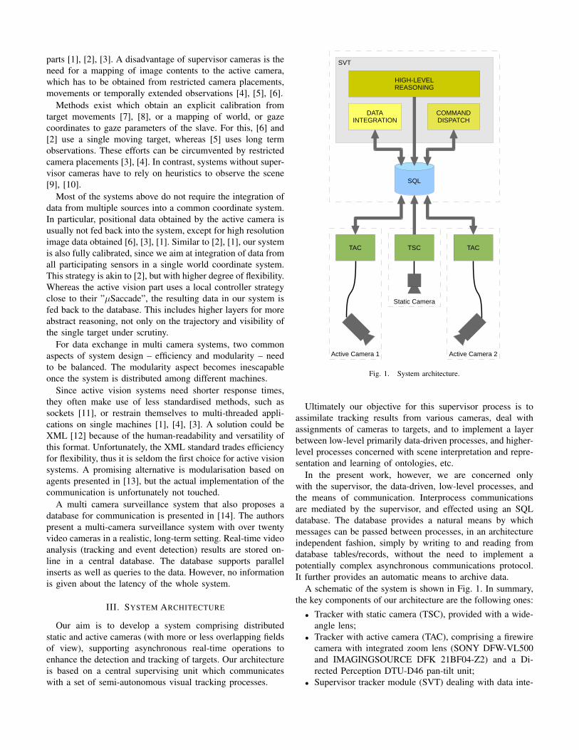
The basic scheme of communication among the trackers,
the database, and the supervisor module is illustrated in Fig. 2
and described next.
1) First, in an offline and one-off procedure, both cameras
are calibrated (section IV-B) with the calibration data
stored in the common repository.
2) The TSC starts retrieving information about the positions
of the tracked targets, in form of regions of interest
(ROI). The position of each target and its ROI is stored
for each time step into an Observation Table.
3) The supervising module continuously reads the new
information stored in the Observation Table. Using the
calibration data and an assumption that the face ap-
pears near the top of the bounding box, the module
computes an approximate set of world coordinates for
the face/head of the target. These data are then stored
together with the ID of the target in the same table.
4) The TAC tracker receives the commands from the SVT
through the Command Table and reads the relative
information being stored into the Observation Table,
thus obtaining an approximated configuration of pan, tilt,
zoom parameters, so that the initial position of the face
can be predicted to initialize the tracking. Stabilized face
images of the target, independently tracked by the TAC,
are finally stored in the Image Table.
IV. IMPLEMENTATION
A. Passive Visual Sensing
The static camera of our system is used for real-time human
detection on wide-angle image sequences. Two different solu-
tions have been implemented, one using a segmentation-based
algorithm by Roth et al. [15] for an initial prototype of the
system, and another one based on the Lehigh Omnidirectional
Tracking System (LOTS) [16], which is part instead of a fixed
installation covering a large public area. As explained next, the
use of two different solutions depends mainly on the particular
location and orientation of the static camera, but it shows also
that the system architecture can easily adapt to different kind
of cameras and tracking algorithms.
The first implementation consists in a multi-object tracker
that performs a per-pixel classification, assigning every pixel to
one of the different objects being tracked, including the static
Fig. 2. Steps of the communication protocol between the TSC and the TACto get stabilized images of the target detected by the TSC.
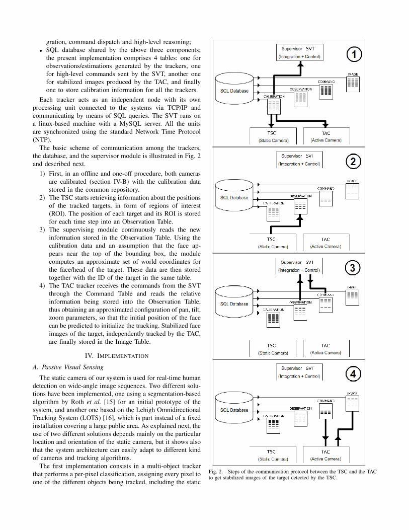
Fig. 3. People detection using LOTS background subtraction. The centroidof each red cluster, corresponding to a human target, is marked with a cross.
background. The classification is based on the probability that
a given pixel belongs to one of the objects given its specific
color and position. These object probabilities are determined
on the basis of two components. First, the observed pixel val-
ues are compared to learned appearance models of the objects,
in order to yield an indication of how similar observed colors
are to these models. The appearance models use Gaussian
mixtures in RGB color space with a single Gaussian per-pixel
for the background and multiple Gaussians for the foreground
models, and are learned and updated continuously. To handle
occlusions, the lack of image depth information is partially
compensated by assuming a horizontal and upright camera
orientation, as well as a planar floor. The reader should refer
to [15] for further information.
To detect people in the large atrium shown in Fig. 3 instead,
we use an implementation of the LOTS algorithm as described
in [17]. This is based on a background subtraction technique
that uses two gray-scale images (of the background) and two
per-pixel thresholds. The latter treat each pixel differently,
allowing the detector to be robust to localized noise in low-
size image regions, and evolve according to a pixel label
provided by a light version of the traditional connected com-
ponent analysis. Small adjacent regions detected by LOTS
are clustered together, and their centroid calculated to give
the target position. The background subtraction well suits our
current installation of the static camera because the targets,
being observed from the top, do not overlap in this case (see
Fig. 3). Details of the original LOTS algorithm can be found
in [16].
B. Calibration
To enable the supervisor to provide demands for the active
camera based on measurements from the static camera, both
were calibrated in a common world coordinate frame. The
intrinsic and extrinsic parameters of the static camera were
determined in standard fashion using multiple images of
planar checkerboard pattern, and yields among other things
the position of a world ground-plane (z = 0).
Since the active camera is used for fixated closed-loop
tracking, there is no need for accurate intrinsic calibration
(though focal-length does play a role as a closed-loop gain in
the system). The active camera is calibrated to the world frame
via a series of fixations of known 3D points. The mapping from
these points, or visual rays, to the joint-angles of the pan-tilt
unit is given succinctly by a 3D-2D projectivity, where the
assumption that the centre of rotation of the device is close to
the optical centre of the camera enables us to treat the active
camera as a “projective pointing device” [18].
At each time step the TSC tracker provides the image
coordinates and the bounding box of each detected target.
Using the assumption that the targets are in contact with the
ground-plane, and the face is a fixed distance above the ground
(in this work 1.7m), the 3D coordinates of the target face/head
are computed by the supervisor module and stored in the
Observation Table.
The accuracy of the extrinsic calibration has an effect on
the relative success of what amounts to hand over from the
static camera to the active camera. However once the active
camera is tracking under closed-loop control, it can continue
to do so independently of the static camera view.
C. Active Visual Tracking
The active tracker module periodically polls the database
to determine if there is a new demand from the supervisor.
If a new demand is present, the pan-tilt unit is immediately
commanded to the appropriate angle, and the zoom level of
the camera set to a value such that, based on the estimated
depth of the target, the face will occupy a fixed fraction of the
field of view.
A face detection module, based on the OpenCV imple-
mentation of the Viola-Jones boosted face detection algorithm
[19] locates the face in the image when the pan-tilt demand
is satisfied and is used to initialise a region-based tracker.
The latter uses a level-set to simultaneously track the image
position, rotation and scale of the target while segmenting it
from the background [20]. This tracker is fast (run-time of
20-30ms) and robust, and provides a smooth demand to a
local velocity control regime. The controller runs at the same
rate as the visual processing and employs a piece-wise linear
proportional control signal as used in [21].
Zoom control on the active camera is slow, and subject to
significant latencies. The scale of the target, as computed by
the level-set tracker, is used to control the zoom to keep the
face to a fixed size, chosen heuristically as a balance between
high-resolution and the ability of the PTZ device to keep the
target in the field of view.
D. System Supervision
The supervisor module is responsible for the data integration
, command dispatch and high-level reasoning of the system.
As anticipated in Fig. 1, this can be thought as a hierarchical
structure of semi-independent processes where the high-level
reasoning part supervises the other two using bi-directional
communication, via SQL queries, for information retrieval and
control.
The main purpose of the data integration process is to collect
sensor observations from one or more cameras and generate
proper trajectories of the current targets, which can be used for
high-level reasoning and for the active cameras. In the current
system, this is implemented as a multi-target tracker based on
Kalman filter and Nearest Neighbour data association using
a constant-velocity model [22], [23]. The multi-target tracker
reads from the Observation Table the 2D world coordinates of
the targets provided by the static camera, and then writes the
relative estimates (2D positions and velocity) into the same
table. In this way, it is possible to identify the trajectory of a
target, as a sequence of estimates with a unique ID, from the
anonymous detections provided by the static camera.
The command dispatch process is responsible for the correct
interpretation and delivery of the high-level commands. These
are sent to the destination cameras through the Command
Table, as explained in IV-E, in some cases together also with
additional arguments (e.g. the ID of a target to follow).
Finally, the high-level reasoning plays the double role of
high-level reasoning process and controller. At the moment,
this is achieved partly using a rule-based approach, and partly
with a real-time implementation of an inference engine based
on fuzzy metric-temporal logic [24]. The high-level reasoner
selects the best TAC to use for tracking a person according
to the his/her location and orientation, in order to increase the
chances of capturing high-resolution images of faces.
E. Data Exchange via SQL Tables
Each component of the system (TSC, TAC and SVT) sends
the local observation/estimation to the Observation Table. The
structure of this table has been defined thus to simplify the
communication between tracker clients and supervisor, and
includes records containing the following 23 fields:
timestamp, source id, target id (identification)
top, left, bottom, right (2D bounding box)
Σ11, Σ12, Σ22 (2D uncertainty)
x, y, z (3D coordinates)
Σxx, Σxy , Σxz , Σyy , Σyz , Σzz (3D uncertainty)
vx, vy , vz (3D velocities)
data (general purpose)
Basically, the first three fields contain the time of the current
information, the ID of the source device (camera) and that
one of the target being followed. The 2D bounding box of
the target, with respect to the current camera’s frame, is then
recorded together with the upper triangular entries of the
relative (symmetric) covariance matrix. The following fields
contain the 3D position of the target, its velocity and its
covariance matrix (upper triangular entries). This information
depends on the extrinsic parameters of the camera and, there-
fore, on the pan/tilt orientation in case of active camera. The
last field is left for the possible transmission of additional data.
Commands are sent by the supervisor module to the TAC
through the Command Table, the structure of which is defined
as follows:
timestamp, destination id, command id (identification)
data (arguments)
The destination TAC of the command is specified in the
“destination id” field. Commands are read by the TAC period-
ically polling the table. At the moment, the list of implemented
commands includes the following 8 ones (but this can be easily
extended):
1) CAPTURE_CALIBRATION_IMAGE – capture image
for calibration setup
2) RELOAD_CALIBRATION_DATA – load calibration set-
tings from database
3) GO_TO_LOCATION – point camera towards a desired
3D point
4) FOLLOW_TARGET – point camera towards a target in
the Observation Table
5) TRACK_TARGET – point camera towards a target and
instantiate a local tracker
6) STOP_TRACKING – stop current target tracking
7) STOP_MOTION – stop every activity
8) SET_DEFAULT_OBSERVATION_VOLUME – set de-
fault view while idle
Finally, the face images captured by TAC while tracking are
stored in the Image Table in records defined as follows:
timestamp, source id, target id (identification)
data, format (image)
where “data” contains the binary image and “format” specifies
the whether it is MONO, RGB, etc.
V. RESULTS
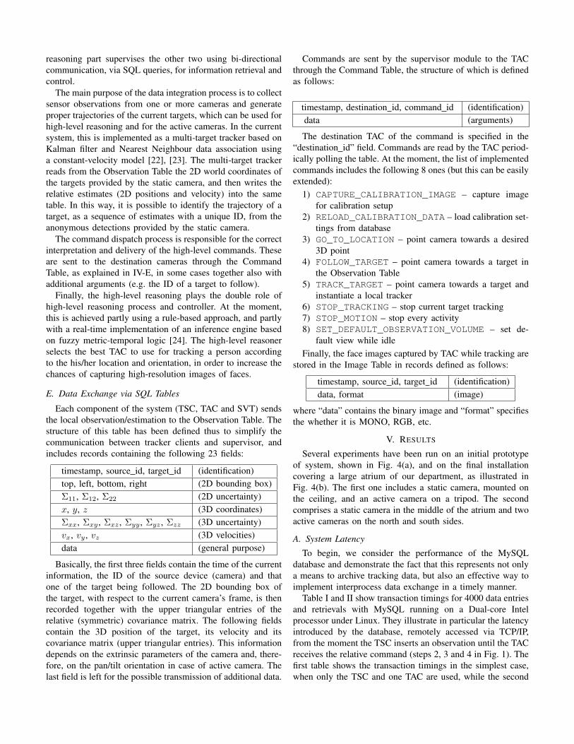
Several experiments have been run on an initial prototype
of system, shown in Fig. 4(a), and on the final installation
covering a large atrium of our department, as illustrated in
Fig. 4(b). The first one includes a static camera, mounted on
the ceiling, and an active camera on a tripod. The second
comprises a static camera in the middle of the atrium and two
active cameras on the north and south sides.
A. System Latency
To begin, we consider the performance of the MySQL
database and demonstrate the fact that this represents not only
a means to archive tracking data, but also an effective way to
implement interprocess data exchange in a timely manner.
Table I and II show transaction timings for 4000 data entries
and retrievals with MySQL running on a Dual-core Intel
processor under Linux. They illustrate in particular the latency
introduced by the database, remotely accessed via TCP/IP,
from the moment the TSC inserts an observation until the TAC
receives the relative command (steps 2, 3 and 4 in Fig. 1). The
first table shows the transaction timings in the simplest case,
when only the TSC and one TAC are used, while the second
(a) (b)
Fig. 4. (a) System setup for the initial prototype (active camera on the bottom right) and (b) for the final installation in a large atrium (static camera on thetop, active on the bottom).
One TAC Min Max Mean SD
TSC → TAC 1.7 59.9 3.7 3.2
TABLE ITIMINGS IN MS FOR 4000 DATA ENTRIES-RETRIEVALS WITH ONE TAC.
Two TACs Min Max Mean SD
TSC → TAC1 1.5 53.4 3.2 1.6
TSC → TAC2 1.8 52.1 3.6 1.5
TABLE IITIMINGS IN MS FOR 4000 DATA ENTRIES-RETRIEVALS WITH TWO TACS.
refers to the case with two TACs simultaneously accepting
commands.
These results are significant because they demonstrate that
the round-trip time for a message from the TSC to the
TAC is sufficiently small as to be negligible compared to
typical camera framerates, even when the database contains
millions of entries (in this case, more than 60 million for the
Observation Table and 18 million for the Command Table). As
shown by our experiments, indeed, the delay is in average one
order of magnitude less than the 30 Hz of a standard camera.
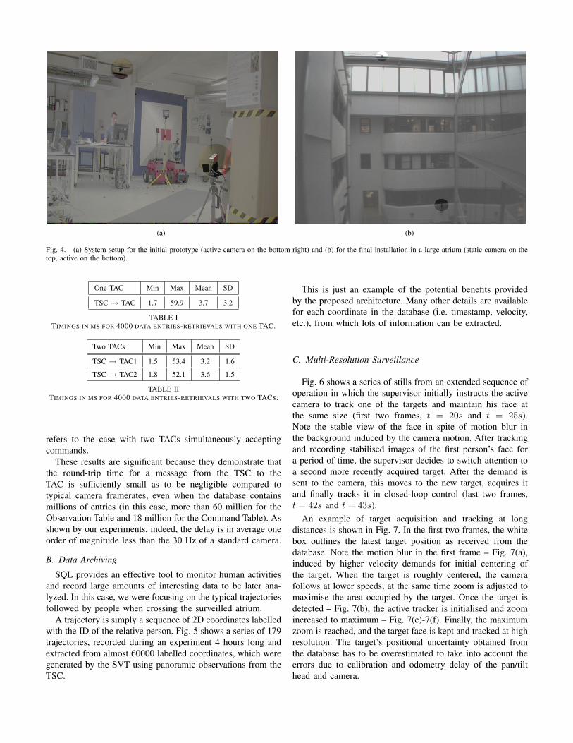
B. Data Archiving
SQL provides an effective tool to monitor human activities
and record large amounts of interesting data to be later ana-
lyzed. In this case, we were focusing on the typical trajectories
followed by people when crossing the surveilled atrium.
A trajectory is simply a sequence of 2D coordinates labelled
with the ID of the relative person. Fig. 5 shows a series of 179
trajectories, recorded during an experiment 4 hours long and
extracted from almost 60000 labelled coordinates, which were
generated by the SVT using panoramic observations from the
TSC.
This is just an example of the potential benefits provided
by the proposed architecture. Many other details are available
for each coordinate in the database (i.e. timestamp, velocity,
etc.), from which lots of information can be extracted.
C. Multi-Resolution Surveillance
Fig. 6 shows a series of stills from an extended sequence of
operation in which the supervisor initially instructs the active
camera to track one of the targets and maintain his face at
the same size (first two frames, t = 20s and t = 25s).
Note the stable view of the face in spite of motion blur in
the background induced by the camera motion. After tracking
and recording stabilised images of the first person’s face for
a period of time, the supervisor decides to switch attention to
a second more recently acquired target. After the demand is
sent to the camera, this moves to the new target, acquires it
and finally tracks it in closed-loop control (last two frames,
t = 42s and t = 43s).
An example of target acquisition and tracking at long
distances is shown in Fig. 7. In the first two frames, the white
box outlines the latest target position as received from the
database. Note the motion blur in the first frame – Fig. 7(a),
induced by higher velocity demands for initial centering of
the target. When the target is roughly centered, the camera
follows at lower speeds, at the same time zoom is adjusted to
maximise the area occupied by the target. Once the target is
detected – Fig. 7(b), the active tracker is initialised and zoom
increased to maximum – Fig. 7(c)-7(f). Finally, the maximum
zoom is reached, and the target face is kept and tracked at high
resolution. The target’s positional uncertainty obtained from
the database has to be overestimated to take into account the
errors due to calibration and odometry delay of the pan/tilt
head and camera.
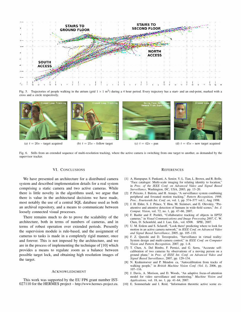
Fig. 5. Trajectories of people walking in the atrium (grid 1 × 1 m2) during a 4 hour period. Every trajectory has a start- and an end-point, marked with across and a circle respectively.
(a) t = 20s – target acquired (b) t = 25s – follow target (c) t = 42s – pan (d) t = 45s – new target acquired
Fig. 6. Stills from an extended sequence of multi-resolution tracking, where the active camera is switching from one target to another, as demanded by thesupervisor tracker.
VI. CONCLUSIONS
We have presented an architecture for a distributed camera
system and described implementation details for a real system
comprising a static camera and two active cameras. While
there is little novelty in the algorithms used, we argue that
there is value in the architectural decisions we have made,
most notably the use of a central SQL database used as both
an archival repository, and a means to communicate between
loosely connected visual processes.
There remains much to do to prove the scalability of the
architecture, both in terms of numbers of cameras, and in
terms of robust operation over extended periods. Presently
the supervision module is rule-based, and the assignment of
cameras to tasks is made in a completely rigid manner, once
and forever. This is not imposed by the architecture, and we
are in the process of implementing the technique of [10] which
provides a means to regulate zoom as a balance between
possible target lock, and obtaining high resolution images of
the target.
ACKNOWLEDGMENT
This work was supported by the EU FP6 grant number IST-027110 for the HERMES project – http://www.hermes-project.eu.
REFERENCES
[1] A. Hampapur, S. Pankanti, A. Senior, Y.-L. Tian, L. Brown, and R. Bolle,“Face cataloger: Multi-scale imaging for relating identity to location,”in Proc. of the IEEE Conf. on Advanced Video and Signal Based
Surveillance, Washington, DC, USA, 2003, pp. 13–20.
[2] P. Peixoto, J. Batista, and H. Araujo, “A surveillance system combiningperipheral and foveated motion tracking,” Pattern Recognition, 1998.
Proc.. Fourteenth Int. Conf. on, vol. 1, pp. 574–577 vol.1, Aug 1998.
[3] J. H. Elder, S. J. Prince, Y. Hou, M. Sizintsev, and E. Olevskiy, “Pre-attentive and attentive detection of humans in wide-field scenes,” Int. J.
Comput. Vision, vol. 72, no. 1, pp. 47–66, 2007.
[4] F. Bashir and F. Porikli, “Collaborative tracking of objects in EPTZcameras,” in Visual Communications and Image Processing 2007, C. W.Chen, D. Schonfeld, and J. Luo, Eds., vol. 6508. SPIE, 2007.
[5] U. M. Erdem and S. Sclaroff, “Look there! predicting where to look formotion in an active camera network,” in IEEE Conf. on Advanced Video
and Signal Based Surveillance, 2005, pp. 105–110.
[6] F. Z. Qureshi and D. Terzopoulos, “Surveillance in virtual reality:System design and multi-camera control,” in IEEE Conf. on Computer
Vision and Pattern Recognition, 2007, pp. 1–8.
[7] T. Chen, A. Del Bimbo, F. Pernici, and G. Serra, “Accurate self-calibration of two cameras by observations of a moving person on aground plane,” in Proc. of IEEE Int. Conf. on Advanced Video and
Signal Based Surveillance, 2007, pp. 129–134.
[8] N. Krahnstoever and P. Mendon ca, “Autocalibration from tracks ofwalking people,” in British Machine Vision Conf. (Vol. I), 2006, pp.107–116.
[9] J. Davis, A. Morison, and D. Woods, “An adaptive focus-of-attentionmodel for video surveillance and monitoring,” Machine Vision and
Applications, vol. 18, no. 1, pp. 41–64, 2007.
[10] E. Sommerlade and I. Reid, “Information theoretic active scene ex-
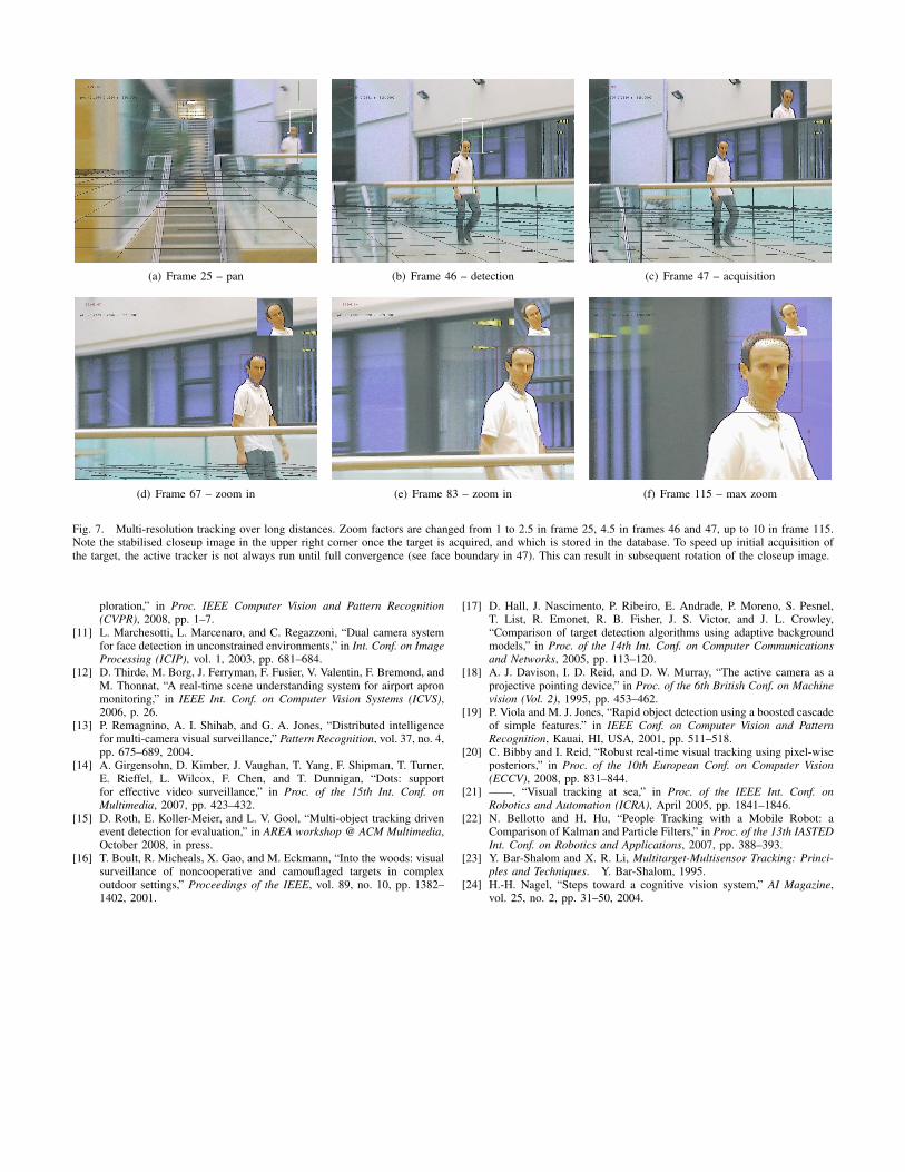
(a) Frame 25 – pan (b) Frame 46 – detection (c) Frame 47 – acquisition
(d) Frame 67 – zoom in (e) Frame 83 – zoom in (f) Frame 115 – max zoom
Fig. 7. Multi-resolution tracking over long distances. Zoom factors are changed from 1 to 2.5 in frame 25, 4.5 in frames 46 and 47, up to 10 in frame 115.Note the stabilised closeup image in the upper right corner once the target is acquired, and which is stored in the database. To speed up initial acquisition ofthe target, the active tracker is not always run until full convergence (see face boundary in 47). This can result in subsequent rotation of the closeup image.
ploration,” in Proc. IEEE Computer Vision and Pattern Recognition
(CVPR), 2008, pp. 1–7.[11] L. Marchesotti, L. Marcenaro, and C. Regazzoni, “Dual camera system
for face detection in unconstrained environments,” in Int. Conf. on Image
Processing (ICIP), vol. 1, 2003, pp. 681–684.[12] D. Thirde, M. Borg, J. Ferryman, F. Fusier, V. Valentin, F. Bremond, and
M. Thonnat, “A real-time scene understanding system for airport apronmonitoring,” in IEEE Int. Conf. on Computer Vision Systems (ICVS),2006, p. 26.
[13] P. Remagnino, A. I. Shihab, and G. A. Jones, “Distributed intelligencefor multi-camera visual surveillance,” Pattern Recognition, vol. 37, no. 4,pp. 675–689, 2004.
[14] A. Girgensohn, D. Kimber, J. Vaughan, T. Yang, F. Shipman, T. Turner,E. Rieffel, L. Wilcox, F. Chen, and T. Dunnigan, “Dots: supportfor effective video surveillance,” in Proc. of the 15th Int. Conf. on
Multimedia, 2007, pp. 423–432.[15] D. Roth, E. Koller-Meier, and L. V. Gool, “Multi-object tracking driven
event detection for evaluation,” in AREA workshop @ ACM Multimedia,October 2008, in press.
[16] T. Boult, R. Micheals, X. Gao, and M. Eckmann, “Into the woods: visualsurveillance of noncooperative and camouflaged targets in complexoutdoor settings,” Proceedings of the IEEE, vol. 89, no. 10, pp. 1382–1402, 2001.
[17] D. Hall, J. Nascimento, P. Ribeiro, E. Andrade, P. Moreno, S. Pesnel,T. List, R. Emonet, R. B. Fisher, J. S. Victor, and J. L. Crowley,“Comparison of target detection algorithms using adaptive backgroundmodels,” in Proc. of the 14th Int. Conf. on Computer Communications
and Networks, 2005, pp. 113–120.[18] A. J. Davison, I. D. Reid, and D. W. Murray, “The active camera as a
projective pointing device,” in Proc. of the 6th British Conf. on Machine
vision (Vol. 2), 1995, pp. 453–462.[19] P. Viola and M. J. Jones, “Rapid object detection using a boosted cascade
of simple features.” in IEEE Conf. on Computer Vision and Pattern
Recognition, Kauai, HI, USA, 2001, pp. 511–518.[20] C. Bibby and I. Reid, “Robust real-time visual tracking using pixel-wise
posteriors,” in Proc. of the 10th European Conf. on Computer Vision
(ECCV), 2008, pp. 831–844.[21] ——, “Visual tracking at sea,” in Proc. of the IEEE Int. Conf. on
Robotics and Automation (ICRA), April 2005, pp. 1841–1846.[22] N. Bellotto and H. Hu, “People Tracking with a Mobile Robot: a
Comparison of Kalman and Particle Filters,” in Proc. of the 13th IASTEDInt. Conf. on Robotics and Applications, 2007, pp. 388–393.
[23] Y. Bar-Shalom and X. R. Li, Multitarget-Multisensor Tracking: Princi-
ples and Techniques. Y. Bar-Shalom, 1995.[24] H.-H. Nagel, “Steps toward a cognitive vision system,” AI Magazine,
vol. 25, no. 2, pp. 31–50, 2004.


![Bellotto Educational Resource DRAFT 8 [CHB] [NEE] [MBS](https://img.pdfslide.us/doc/110x75/61cfbf0ef761990b0d21b667/bellotto-educational-resource-draft-8-chb-nee-mbs-.jpg)