Embed Size (px)
Citation preview

A DEVICE TO ESTIMATE OVERHEAD LINE FAULT LOCATION IN 2x25 kV ELECTRIC TRACTION: PROTOTYPE OVERVIEW
Umberto M Cella, :Peter F Nussey, Igor Perin, Truc V Tran
Aurizon, 192 Ann St Brisbane QLD 4000, AUSTRALIA
Corresponding Author: [email protected]
SUMMARY
Aurizon’s Blackwater and Goonyella coal rail systems use 2x25 kV electrification. The overhead line can have small electrical clearances and the railway usually runs through bushland, paddocks and uninhabited areas. These factors contribute towards a significant number of faults occurring on the overhead lines.
If the circuit does not hold after one reclosing attempt, intervention is required on site to remove the foreign object causing the short circuit. However, by relying solely on the knowledge of which circuit breaker has tripped, it is only possible to pinpoint the fault down to a whole electrical section, which is the track comprised between a feeder station and a track sectioning cabin. An electrical section can be tens of km long. In this case locating and rectifying the fault can be time-consuming and difficult.
For these reasons, QR introduced almost three decades ago fault locator devices named QRFLs, which provide the Electric Control Officer (ECO) with an estimate of the location along the track within the section where the fault occurred. Currently, the technology used in the existing devices is ageing and the componentry is becoming obsolete: therefore, a new system is being designed and deployed.
This paper firstly presents an overview of the fault location system. It then introduces the theory of fault location based on return current measurement, followed by a description of the currently installed fault locator system and of its characteristics and technical challenges. The technical challenges encountered with the system are outlined, and improvements introduced with the new design are described.
1. INTRODUCTION The QRFLs are installed at any location where Autotransformers (AT) are connected to the traction power supply: at AT sites along the track, at Feeder Stations (FS) or at Track Sectioning Cabins (TSC).
The QRFLs within an electrical section (FS to TSC) are connected to each other via a communications line, and the whole string of QRFLs is connected to the SCADA (Supervisory, Control And Data Acquisition) at the FS and at the TSC. Each string of QRFLs is part of the fault location system.
The fault location system has two main functions:
1) It provides the ECO an estimate of the position of an electrical fault occurring on the traction power system along the track. An accurate estimate of the location of the fault allows the maintenance crew to reach in a timely manner the affected item of plant.
2) In case of severe malfunctioning of an autotransformer located along the track, it trips the breakers that supply the relevant electrical section of the traction power system, thus de-energising the faulty autotransformer.
Currently, the fault location system uses mark 2 version QRFLs (QRFLmk2).
The QRFLs mk2 are becoming increasingly difficult to maintain due to obsolescence of some components, mainly residing in the QRFL-QRFL communication function.
The concurrent obsolescence of both devices requires an update of the design of the QRFL to maintain the functionality of the fault location system. For this reason, a QRFL mk3 device is required. The older infrastructure (based on VF interface units) used by the QRFL mk2 will be gradually substituted with Ethernet based infrastructure.
The QRFL mk3 will be used either as a replacement for a faulty mk2 device in a site with old telecommunication infrastructure, or in a site where the telecommunication infrastructure is already upgraded (Ethernet).
Therefore, the QRFL mk3 will:
• Preserve QRFL mk2 functionality and characteristics
• Operate within the current telecommunications system and work with mk2 devices
RBroc
SUPPORTED BY
PLATINUM PARTNER
HOST SPONSORS
RBroc
SUPPORTED BY
PLATINUM PARTNER
HOST SPONSORS
RBroc
SUPPORTED BY
PLATINUM PARTNER
HOST SPONSORS
OVERHEAD POWER
RBroc
SUPPORTED BY
PLATINUM PARTNER
HOST SPONSORS
• Operate within the upgraded tele-communications system and work with mk3 devices
2. FAULT LOCATION THEORY
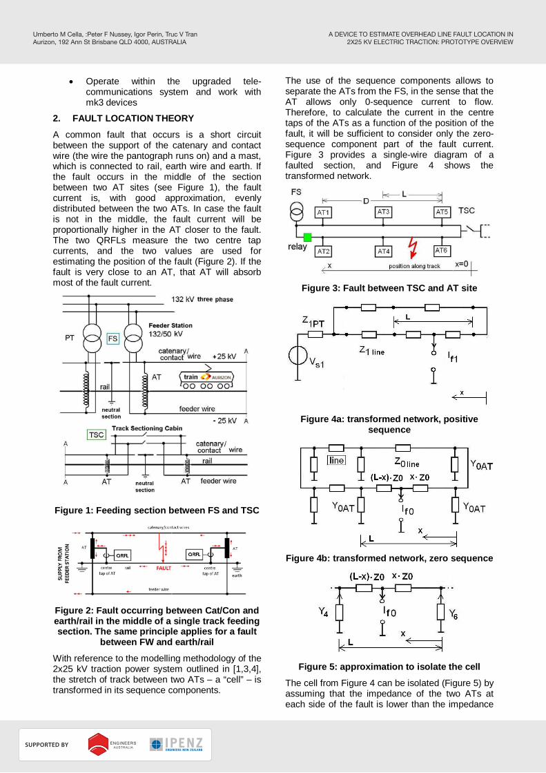
A common fault that occurs is a short circuit between the support of the catenary and contact wire (the wire the pantograph runs on) and a mast, which is connected to rail, earth wire and earth. If the fault occurs in the middle of the section between two AT sites (see Figure 1), the fault current is, with good approximation, evenly distributed between the two ATs. In case the fault is not in the middle, the fault current will be proportionally higher in the AT closer to the fault. The two QRFLs measure the two centre tap currents, and the two values are used for estimating the position of the fault (Figure 2). If the fault is very close to an AT, that AT will absorb most of the fault current.
Figure 1: Feeding section between FS and TSC
Figure 2: Fault occurring between Cat/Con and earth/rail in the middle of a single track feeding section. The same principle applies for a fault
between FW and earth/rail
With reference to the modelling methodology of the 2x25 kV traction power system outlined in [1,3,4], the stretch of track between two ATs – a “cell” – is transformed in its sequence components.
The use of the sequence components allows to separate the ATs from the FS, in the sense that the AT allows only 0-sequence current to flow. Therefore, to calculate the current in the centre taps of the ATs as a function of the position of the fault, it will be sufficient to consider only the zero-sequence component part of the fault current. Figure 3 provides a single-wire diagram of a faulted section, and Figure 4 shows the transformed network.
Figure 3: Fault between TSC and AT site
Figure 4a: transformed network, positive
sequence
Figure 4b: transformed network, zero sequence
Figure 5: approximation to isolate the cell
The cell from Figure 4 can be isolated (Figure 5) by assuming that the impedance of the two ATs at each side of the fault is lower than the impedance
A DEVICE TO ESTIMATE OVERHEAD LINE FAULT LOCATION IN 2X25 KV ELECTRIC TRACTION: PROTOTYPE OVERVIEW
Umberto M Cella, :Peter F Nussey, Igor Perin, Truc V TranAurizon, 192 Ann St Brisbane QLD 4000, AUSTRALIA
RBroc
SUPPORTED BY
PLATINUM PARTNER
HOST SPONSORS

of the line that continues from them in each direction. This is an approximation, and its purpose is mainly to focus on the linear relationship that exists between the position of the fault within the cell and the currents in the two ATs.
The equivalent impedances of the two branches can be expressed as:
( )
⋅+=
⋅−+=
line
line
ZxY
Y
ZxLY
Y
,06
6
,04
4
11'
11' (1)
Z0line is the per-km zero sequence impedance of the overhead line, and Y4 and Y6 are the zero sequence impedances of the AT sites. These can vary as the FS and the TSC have two ATs in parallel (one for each track), and the AT sites only one AT per track (in Aurizon’s network they are not parallel posts). The two AT currents I4 and I6 can be expressed as a function of the zero sequence component of the fault current If:
line
linef ZLYY
ZxYII
,046
,064 11
1⋅++
⋅+⋅= (2)
( )line
linef ZLYY
ZxLYII
,046
,046 11
1⋅++
⋅−+⋅= (3)
The two ratios of AT current to total current are introduced and calculated at each end of the faulted section:
line
line
f ZLYYZxY
IIh
,046
,064
111
⋅++
⋅+== (4)
linex ZLYY
Yqh
,046
610 11
1⋅++
===
(5)
lineLxf ZLYYYq
II
,046
42
6
111'
⋅++==
=
(6)
It can be demonstrated that the distance of the fault from AT6 is equal to:
( )112 '1
qhqq
Lx −⋅−−
= (7)
This is valid for any cell within a feeding section, provided that the origin of the coordinate and the position of the two ATs with respect to that coordinate are respected.
The position of the fault can therefore be calculated from the currents I4 and I6 alone, and from two constants q1 and q2’ that depend only on the geometry of the system. This formula is inserted in the SCADA system and the constants q1 and q2’ are tabulated for each electrical section.
It must be stressed that the drawback of this calculation of the position of the fault works only for faults that produce a zero sequence current, which are catenary-earth and feeder-earth faults. A catenary-feeder fault is symmetrical and does not use the ATs as return path. However, this kind of fault is uncommon and, if it occurs, it usually degenerates in an earth fault anyway.
3. CURRENT QRFL CHARACTERISTICS
This section illustrates the principle of operation of the fault locator system.
The existing fault locator system performs the following basic functions:
• Measures and records fault current in ATs and transmits the result via the V23-based [5] channel to the master RTU (Remote Terminal Unit) and then to SCADA
• Transmits transformer alarms via the V23-based channel to the Master RTU and then to SCADA
• Transmits transformer trip signals from AT site via the V23-based channel to all QRFLs in the section, including Master and Sub-master which trip the breakers located at the FS and TSC sites
• Operates in normal and extended feeding mode
The fault locator system consists of a series of measurement units, referred to as fault locator units or QRFL units. Each QRFL is located nearby an AT or a group thereof, either at a FS, TSC or AT site along the track.
Figure 6: QRFL general arrangement
The QRFL measures the current that flows in the return leg (Centre Tap) of the autotransformer(s).
The SCADA system determines the location of the fault by examining the simultaneous return currents from all units in a section and by performing a simple ratio calculation on the largest two currents.
A DEVICE TO ESTIMATE OVERHEAD LINE FAULT LOCATION IN 2X25 KV ELECTRIC TRACTION: PROTOTYPE OVERVIEW
Umberto M Cella, :Peter F Nussey, Igor Perin, Truc V TranAurizon, 192 Ann St Brisbane QLD 4000, AUSTRALIA
RBroc
SUPPORTED BY
PLATINUM PARTNER
HOST SPONSORS

A section of fault locators can consist of up to ten QRFL units. A fault locator unit is placed at every AT site along the feeding section, including FS and TSC. A current transformer is installed on the centre leg of each AT to allow the fault locators to monitor the current flowing in the earth return connection.
One QRFL string is installed for each electrical section, not for each track. For example, a single QRFL string serves a dual track section. A single electrical section may supply overhead power to one or more tracks.
It is the RMS (Root Mean Square) value of the current flowing in the centre tap during a fault that is used for determining the location of the fault.
QRFL units communicate with each other along a specially assigned communication channel. Each section has its own channel. Inter-unit communication is achieved by means of 1200 baud half duplex modems fitted to each QRFL unit. The Power Supervisory and Control System (PSCS) has no direct access to this communication channel at all.
Every fault locator unit within a section is installed with a unique physical unit address between 0 and 9. This unit address is used by the master QRFL unit (unit 0) or Sub-Master (unit 9) to identify other units on the line and is also used by the units 0 to 9 themselves to determine whether they are slaves (units 1 to unit 8), sub-master (unit 9) or master unit when there is a communication loss between units 0 or 9 to the RTU. The addresses are allocated via a DIP switch mounted on the circuit board.
A fault locator section is defined as the length of track between a FS and a TSC.
QRFL units communicate with the PSCS only through the RTUs of the PSCS. Only two units within a fault locator string are connected to these RTUs; these units are referred to as the Master unit and Sub-Master unit, with a corresponding address of 0 and 9 respectively. Either unit can act as the “host”, hereby referred to as the “current master”. The slave units, which are the intermediate units, can have a unit address in the range 1 through 8.
Data is passed to the RTU associated with Unit 0 or Unit 9 via an RS232 serial port. All RTU units direct the information received from their associated QRFL unit to the PSCS.
The system has been designed so that either Unit 0 or Unit 9 can be the current master at any given time as a result of a communication failure between the units or via PSCS control.
Unit 0 is by default the current master under normal circumstances, but should Unit 0 become
faulty in any way or go off-line during maintenance a “Take-over” is performed in which Unit 9, which was previously the sub-master, becomes the current master unit. This is a fail-safe feature of the system. The current master unit is the only unit that actually communicates status information to the RTU. All commands issued from to a fault locator section will be directed to the current master unit.
The current master unit (either unit 0 or unit 9) is responsible for all control within the QRFL section. This control involves the polling of all other units in the section to determine if a change in status has occurred (for example an alarm has occurred), and to determine the status of the sub-master. The majority of the communications between QRFL units are between the master and the sub-master unit. The master unit continuously polls the sub-master to determine if the sub-master has detected a START [7]. A START is generated by a trip of the breakers at FS and TSC that follows a fault within the feeding section, either on the overhead conductors of at the AT site. If a START was detected, the master will issue a global command (to all units) to take a snapshot of the current present in the centre tap of the autotransformers at the time the fault caused the trip. A START command can also be generated by the ECO o locally by maintenance staff to initiate the same process.
Within each feeding section the system as a whole is fault tolerant in the sense that it tolerates a single QRFL unit failure or a failure within an RTU unit. An individual QRFL unit may cease to respond or simply report that an internal consistency check has failed. Such a unit could be unit 0 at the FS, and under such conditions, unit 9 at the TSC will become the current master.
The system also tolerates a break in the V23-based communication channel. If this occurs it is possible that the entire track section could be split into two sections. One half of the communication section contains unit 0 and the other half contains unit 9. The slave units in between are able to communicate to only one of those two units, the exact arrangement depending on the wiring and exactly where the break occurs. In this situation a two-master status is assumed which ensures that fault signals will still be transmitted to the master unit to initiate a trip signal to the protection relays.
4. QRFL MK3 CHARACTERISTICS
In this section the characteristics and desired improvements to the system are outlined.
A summary of current issues and how they are addressed in the new design is given in Table 1.
Issues range from design flaws to new characteristics to respond to needs that became apparent in time, such as the ability of connecting
A DEVICE TO ESTIMATE OVERHEAD LINE FAULT LOCATION IN 2X25 KV ELECTRIC TRACTION: PROTOTYPE OVERVIEW
Umberto M Cella, :Peter F Nussey, Igor Perin, Truc V TranAurizon, 192 Ann St Brisbane QLD 4000, AUSTRALIA
RBroc
SUPPORTED BY
PLATINUM PARTNER
HOST SPONSORS

remotely to the QRFL or downloading a log of the alarms and communication events.
Other issues are the obsolescence of components and systems, or mere design flaws that were
recognisable only with a prolonged usage of the devices and that went unnoticed during acceptance tests of the MK2 devices.
Table 1: issues with current QRFL and solution in MK3 design
Issue Solution Section
ECO receives alarm flagging communications errors
The protocol is streamlined and self-tests, which were once required for older RAM chips are eliminated
4.9
Noise generated on the QRFL board Improve earthing on the board and avoid earthing loops in the wiring
4.5
MK2 QRFL has V.23 line voltage levels that are not adjustable over a wide range
Standardize to -6 dBm to comply with VF card interface
4.9
Only 4 current transformer inputs are available: in situations where more than 4 ATs are installed on site, a summing CT is required
provide more inputs to cater for various feeding arrangements
4.3
Obsolete V23 modem chip Find a future proof design for V23 interface 4.9
No data logging Provide memory for data logging and facility for download
4.7
Site inspection is required for upgrades and resets
Remote diagnostic facility 4.10
V.23 interface (voice line) equipment will be obsolete
Ethernet connectivity 4.9
Finding the fault waveforms within the recording on the circular buffer is based on a fixed time delay used to shift the measurement point back in time: this can fail if line latency varies
The waveform in the circular buffer is timestamped and the time stamp transmitted with the START command
4.1
4.1 Recording of fault current
The fault locator continuously samples the current in the centre tap of the AT and stores the samples in an internal circular buffer memory, which holds 2.56 s of samples at 1.6 kHz. Upon fault detection by the protection relays at the outgoing circuit breakers, a START signal is sent by the protection relay to the Master or Sub-Master unit, which in turn send a “Take Snapshot” message to all the fault locators in the loop, to take a snapshot of the fault current in the ATs and calculate the RMS value of the fault current. The calculated fault current is sent to the Master unit at the next polling cycle.
A timing example of a recording sequence with trigger points and time delays is shown in Figure 7.
The retrieval of the recorded fault current will be initiated through the following actions:
1. The master polls the group units after a trip from a Feeder Station or a Track Sectioning Cabin “Take Snapshot” event.
2. The fault data result from each fault locator in the same feeding section will be processed and an RMS value calculated. RMS fault currents from each fault locator in the section will be sent to the PSCS system.
Figure 7: Sample of fault waveform with
indicative timing of signals and events [7]
The operator of the SCADA control panel will be able to retrieve any recorded fault current for any particular fault locator in the system.
The maximum fault current through the centre tap of the AT can be up to 12 kA RMS with an X/R of
A DEVICE TO ESTIMATE OVERHEAD LINE FAULT LOCATION IN 2X25 KV ELECTRIC TRACTION: PROTOTYPE OVERVIEW
Umberto M Cella, :Peter F Nussey, Igor Perin, Truc V TranAurizon, 192 Ann St Brisbane QLD 4000, AUSTRALIA
RBroc
SUPPORTED BY
PLATINUM PARTNER
HOST SPONSORS

10. This corresponds to a peak of 29.4 kA (for maximum asymmetry = worst fault time).
Number of inputs to be provided (see also Section 3.4.2):
• Seven separate signal conditioning and A/D conversion channels
• Each one of them will be connected to the primary of a separate QRFL CT (current transformer).
• Each CT will have one primary and one secondary
The characteristics of the A/D converter used in the QRFL mk3 are equal or better to those of QRFL mk2.
The samples will be time-stamped in memory so that the QRFL mk3 can calculate the fault current at the correct time. Also, time-stamping will enable the user to retrieve fault history data stored by the various units in the sections and compare them.
Each time a fault occurs (START condition detected, see [7] Section 3.4), the whole buffer will be saved, as a time-stamped series, in local memory for retrieval by the user at a later stage. The waveform saved will not be “wrapped around”, that is the starting point will be at the beginning of the saved recording, and the end point at the end of the saved recording.
This faults record will be downloadable by the user onto a USB key on site, or remotely via web-based interface.
The measurement chain comprised between each and every one of the current inputs and the computed RMS value of the 50 Hz component will be capable of:
• Adding the samples of the seven inputs
• Extracting the 50 Hz component of resulting fault current waveform
• Excluding the DC transient component and the harmonic components
• Calculating the RMS value of the 50 Hz component at any point along the waveform, especially when the decaying DC component is significant
• Maximum measurement error:+/- 5%
• Calibration via user menu with offset and slope factors
As an example, refer to the sample waveform in Figure 8.
The QRFL calculates the RMS value of the fault current when requested by the Master (see [7] Section 3.4). There is a delay between the time the
fault begins and time the QRFL receives the TS (see 4.4.1 in [7]) command. This delay varies according to:
• Whether the START (see [7], Section 3.4) was detected by the Master or Sub-master
• Whether the fault was detected by the protection relay or by the QRFL at the AT site
• The latency of the telecommunication system
• The time taken for the protection relay to send trip signal to breaker and QRFL
Figure 8: Sample fault current waveform; duration = four periods
4.1.1 Time delay issues
The QRFL mk2 currently relies on a fixed time value to look "backwards" into the fault current recording in order to find the correct starting point in the waveform to calculate the RMS value (TIME variable in NOVRAM (non-volatile RAM), see TS in [7] in Section 4.4.1 and in Section 3.4). The value of this time difference is dictated by the master and compensates for the time delays occurring from the issue of the START signal and the receipt of the TS command by the slave. This principle is currently implemented with the V23-based protocol for QRFL-QRFL communication. Figure 9 provides a sample timing sequence.
With the introduction of the Ethernet-based communication between QRFLs, the latency of the network can be both longer and more variable than with V23-based communication.
When using Ethernet-based communications between QRFLs, even if the communication delay is longer and more variable, the QRFLs will still be able to calculate the RMS current at the correct time location within the “fault” part of the recorded waveform (i.e. not before the fault started or after the fault was cleared).
Absolute time-synchronisation of each QRFL can be a suitable option to preserve correct individuation of the fault by each QRFL in its
A DEVICE TO ESTIMATE OVERHEAD LINE FAULT LOCATION IN 2X25 KV ELECTRIC TRACTION: PROTOTYPE OVERVIEW
Umberto M Cella, :Peter F Nussey, Igor Perin, Truc V TranAurizon, 192 Ann St Brisbane QLD 4000, AUSTRALIA
RBroc
SUPPORTED BY
PLATINUM PARTNER
HOST SPONSORS

waveform recording. A solution is that the Master QRFL, when operating via Ethernet, will transmit a TS command that contains, rather than the delay, the time that the master or Sub-Master QRFL sensed the trip signal from the protection relay. Some solutions for time synchronisation that will be tested are:
• Real Time Clock (RTC) on each QRFL adjusted by GPS time at the site
• Time synchronisation via Ethernet
Figure 9: Sequence for fault detection and QRFL signals. The times showed are for
illustration purposes only. 4.2 AT protection function
This is a description of the sequence of operations which occurs when the QRFL unit at an AT site receives a trip signal. This protection functionality is safety critical and will be maintained in the mk3 QRFL.
1. An auto-transformer short-circuits (trip X or Y input goes high).This condition is immediately sensed by the QRFL Unit.
2. The unit then transmits a TRIP command [7] to all other fault locator units in the same section.
3. The TRIP message is received by all units which in turn respond by closing their respective TRIP relays (if fitted). The TRIP outputs are closed for one second. This causes a circuit breaker trip in both the Feeder Station and the TSC, resulting in
power being removed from the faulted track section.
4. The tripping of the circuit breakers also causes a START signal to be generated in both the Feeder Station and the TSC (Unit 0 and Unit 9 respectively).
5. The master unit processes the START signal and transmits a “Take Snapshot” command. This causes all units to take a snapshot and commence RMS computations upon that snapshot.
6. The master unit polls the other units for these RMS values.
4.3 Extended feeding mode
Extended feeding is a switching arrangement in the traction power system where a FS supplies power past a TSC whose bus section breaker is closed, thereby reaching all the way to the next FS, which is out of service.
The extended feeding function is triggered in the QRFL by a signal from the Bus Section circuit breaker at the FS or TSC when it is placed into extended feeding mode by the ECO. This signal energises relay RL1 on the interface board effectively connecting all the centre tap CTs of all the ATs on site in parallel via the CT of the QRFL to add their currents. The Master / Submaster arrangement at the relevant site is not affected by extended feeding. The CTs need to be connected in parallel because the fault current returning to the FS, TSC or AT site will be shared equally among all the ATs that share the same Cat/Con and FW connection. If, due to an extended feeding arrangement, the two buses are connected in parallel, the fault current will return via and be shared among all the ATs connected to those two buses.
Depending on operational or maintenance requirements, it is possible at the FS or at the TSC to connect one or more 50 kV buses together via the bus section breakers. This operation connects the ATs of each bus in parallel. Therefore, the fault current, which returns to the Cat/Con-FW circuit via the centre taps of the ATs will distribute in all the centre taps of the ATs that are connected in parallel.
To achieve a correct measurement of the total fault current returning to the site, all the currents of the ATs that are connected in parallel will be added. Therefore, the QRFL mk3 will be able to add different channels according to different feeding arrangements.
There are FSs in Aurizon’s system where there are more than 4 ATs. However, the QRFL mk2 has only four inputs, thus requiring an external summation CT. To avoid this, QRFL mk3 will be
A DEVICE TO ESTIMATE OVERHEAD LINE FAULT LOCATION IN 2X25 KV ELECTRIC TRACTION: PROTOTYPE OVERVIEW
Umberto M Cella, :Peter F Nussey, Igor Perin, Truc V TranAurizon, 192 Ann St Brisbane QLD 4000, AUSTRALIA
RBroc
SUPPORTED BY
PLATINUM PARTNER
HOST SPONSORS

fitted with seven inputs whose currents are added in software.
4.4 Conditions of installation
The QRFL mk3 will operate under the following ambient conditions:
Site altitude: up to 300m above sea level
Air Quality: polluted with coal dust and occasional dust storms
Maximum air temperature: 60°C for 10 h
Minimum Air temperature: -5°C
Relative Humidity: Up to 100%
Average annual rainfall: Up to 1900mm
4.5 Power supply
48V DC power supply is available at all sites. DC supply limits are 48V ±15%. This equates to a voltage range of 40.8V to 55.2V.
Figure 10: noise introduced by circuit board on V.23 receive line input. The combination of ringing at the end of the V.23 waveform and of the noise added onto the input of the modem causes a glitch in
the data byte (demodulated signal)
Power supply inputs must not create Earth loops when connected to existing wiring on site. Also, noise produced by switch mode power supplies on board will be kept to a minimum, as it currently appears to affect the modem inputs of the V.23 interface. This is sometimes causing glitches and errors in the communication, as displayed in Figure 10.
4.6 Binary and analogue inputs
The QRFL mk2 has the following alarm inputs: • ALARMV
• ALARMW
And the following trip inputs:
• TRIPX
• TRIPY
A START input is provided as well. The START input is connected to the feeder protection relays and is energised when a trip signal is sent to the breaker.
For the QRFL mk3, 12 further optoisolated inputs are required. Excluding START this is a total of 16 inputs of which:
• 12 are to be binary
• 4 are to be 4-20mA analogue, accuracy ± 5%, averaged every ten seconds
More inputs are required to monitor additional variables in the future, such as temperatures of the ATs on the analog inputs, and other alarms on the digital inputs.
4.7 Logging of events
Data logging will be provided in QRFL mk3. This functionality is very important for accessing historical fault data, alarm and trip and analog input level data, and for generic diagnostic purposes
The log will not be deleted upon reset of the unit. Once the log reaches the maximum memory size available, oldest entries will be eliminated. The log will not wrap, i.e. first entry will be the oldest, last entry the newest.
A DEVICE TO ESTIMATE OVERHEAD LINE FAULT LOCATION IN 2X25 KV ELECTRIC TRACTION: PROTOTYPE OVERVIEW
Umberto M Cella, :Peter F Nussey, Igor Perin, Truc V TranAurizon, 192 Ann St Brisbane QLD 4000, AUSTRALIA
RBroc
SUPPORTED BY
PLATINUM PARTNER
HOST SPONSORS

The log will be easy to chart in an excel spreadsheet (i.e. select the column and create chart without manipulations), and the log memory will be non-volatile.
The QRFL mk3 will have a USB port where a USB memory stick can be inserted to download the event log and the waveform log on site. The local download will be initiated via the user menu. The download operation will not clear the events memory or the waveform memory. Remote downloading via Ethernet connection will be available as well via a web-based user interface.
Figure 11: Typical installation of QRFL
mk2 4.8 Compliance with standards
The QRFL mk3 will comply with the following standards [2]:
• AS/NZS 61000.6.4:2012 Electromagnetic compatibility (EMC) - Part 6.4: Generic standards - Emission standard for industrial environments.
• AS/NZS 61000.4.2 (Electrostatic discharge immunity tests): level 3, 6 kV, rise time 0.8 ns
• AS/NZS 61000.4.3 (radiated, radio frequency, electromagnetic field immunity test): level 3, 80-1000 MHz, 10 V/m, AM 80% @ 1 kHz sine wave (to be performed with the lid of the enclosure open)
• AS/NZS 61000.4.4 (electrical fast transient/burst immunity tests): level 4, 4 kV peak on power ports and 2 kV peak on signal ports, 5 kHz repetition
• AS/NZS 61000.4.5 (surge immunity test): level 4, open circuit V = 4 kV, rise/half value time = 1.2/50 us
• IEC 61000.4.17 (ripple on d.c. input power port immunity tests): 5% of Vnom, 0.1 to 500 kHz (see AS/NZS 61000.2.5)
• IEC 61000.4.29 (voltage dips, interruptions and voltage variations on d.c. input power ports, immunity test): fluctuation <3%, dip 10%-99% < 0.8 s, interruption < 0.6 s
4.9 Communication
QRFL-QRFL communication will occur either via:
• V.23 voice channel
• UDP over Ethernet
Not all AT sites are connected to Aurizon’s fibre network. Therefore, QRFL mk3 will maintain both the old V.23 interface which uses a voice frequency modem, and will have an Ethernet port as well.
The modem chip used in Mk2 QRFL is now obsolete. A replacement device was found and will be tested and implemented.
Better regulation of the output and input levels is required. QRFL mk1 had a variable attenuator that was trimmed to suit the attenuation of the copper party line. Now most of the QRFLs mk2 have only a short run of cable to connect to a VF card. The standard value is -6 dBm. An I2C-controlled attenuator will be provided to change the input/output levels to suit the requirements of the VF card. Some sites still have a copper run to reach the closest telecom infrastructure: in these cases, the transmit and receive levels will be adjusted so that the line attenuation is considered.
The communication protocol will be the same for both V.23 and UDP, but with UDP the current 1-byte commands [7] will be encapsulated in a suitable packet.
QRFL mk2 has vestigial issues in terms of poor handling and reporting of communication errors. Better error checking and redundancy will be implemented to minimise the number of communications failure alarms received by ECO. Also, the improved noise level on the board will minimise detection of spurious bytes by the v.23 modem UART.
4.10 User Interface
The local user interface will be in the form of an LCD screen whose content can be navigated via a keypad.
The remote user interface will be a web page hosted by an embedded server (Mentorel embedded system module, running a Linux
A DEVICE TO ESTIMATE OVERHEAD LINE FAULT LOCATION IN 2X25 KV ELECTRIC TRACTION: PROTOTYPE OVERVIEW
Umberto M Cella, :Peter F Nussey, Igor Perin, Truc V TranAurizon, 192 Ann St Brisbane QLD 4000, AUSTRALIA
RBroc
SUPPORTED BY
PLATINUM PARTNER
HOST SPONSORS

operating system). The web page will allow the same functionality of the local user interface.
The user interface will have four states:
1. Idle mode, which is the normal state; it will show information useful for a first visual inspection on site (see Section 3.12.1 of this specification)
2. Settings mode, which is entered when any key (apart from the backlight key) is pressed; it will allow the user to change the settings of the QRFL mk3 and to check the states of the inputs and outputs (see Section 3.12.2 of this specification)
3. Fault mode, which is entered automatically when sensing a START condition or receiving a TS command (see Section 3.12.3 of this specification)
4. Debug mode, which is selected via menu and exited when any key (apart from backlight key) is pressed (see Section 3.12.4 of this specification)
No external devices will be used for commissioning, setting, calibration, monitoring. If any operation is done remotely, only a PC with a web browser will be sufficient.
The user screen and settings facility via user menu will be replicated on a web page accessible via the remote monitoring Ethernet port of the QRFL mk3.
The web-based interface will allow the user to:
• download remotely the events and waveform logs stored in memory
• download remotely a file, in text format, containing all the settings of the QRFL mk3
• use the saved settings file to set another QRFL mk3 by uploading it remotely to the device
5. CONCLUSION
The principle of fault location in the 2x25 kV system was described. This is believed to be a very elegant solution, which however presents a few challenges.
The main challenge is the network latency that may undermine the calculation of the RMS value of the centre tap current at the time of the fault. This will be solved by time-synchronising the QRFL units.
The current QRFL mk2 units were described and the defects that the QRFL mk3 design is intended to eliminate were explained.
It is concluded that the new design will overcome present issues and improve the safety and reliability of the electrified coal rail.
The new QRFL mk3 is also expected to decrease the site attendance as it will be able to provide additional remote monitoring functionality in a compact, single-device solution.
6. REFERENCES
1. Cella, U.M., Modelling methodology for autotransformer rail traction power system based on symmetrical components, Asia Modelling Symposium 2013, Kuala Lumpur, Malaysia
2. AS/NZS 61000.1.1 Electromagnetic Compatibility (EMC) – General – Application and interpretation of fundamental definition and terms
3. Cella, U.M., Tran, T., Nussey, P., Perin, I., Optimal placement of trackside autotransformers for 50 kV system in relation to track profile, in proceedings of Conference on Railway Excellence CORE2014, Adelaide, 5-7 May 2014.
4. Cella, U.M., Tran, T., Nussey, P., Matair, S., Modelling of traction power system for evaluation of harmonic distortion in relation to route capacity, in proceedings of Conference on Railway Excellence CORE2014, Adelaide, 5-7 May 2014.
5. ITU Recommendation V23, Data communication over the telephone network, 1988
6. ECO’s manual / Queensland Rail Fault Locator System, 02/1994
7. Comperex Pty Ltd, Return current fault locator system – functional specification, ver. 1.1, 02/1989
A DEVICE TO ESTIMATE OVERHEAD LINE FAULT LOCATION IN 2X25 KV ELECTRIC TRACTION: PROTOTYPE OVERVIEW
Umberto M Cella, :Peter F Nussey, Igor Perin, Truc V TranAurizon, 192 Ann St Brisbane QLD 4000, AUSTRALIA
RBroc
SUPPORTED BY
PLATINUM PARTNER
HOST SPONSORS