Embed Size (px)
Citation preview
Draf
t Ken
ya S
tand
ard
for B
allot
ing —
Not
to b
e Ci
ted
as K
enya
Sta
ndar
d
KENYA STANDARD KS 1878-3:2010 ICS 29.240.20
© KEBS 2010 First Edition 2010
Electrical power transmission and distribution — Guidelines for the provision of electrical distribution networks in residential areas — Part 3: Overhead distribution in very low, low and moderate consumption areas, including rural areas and informal settlements
BALLOT DRAFT, MAY 2010
Draf
t Ken
ya S
tand
ard
for B
allot
ing —
Not
to b
e Ci
ted
as K
enya
Sta
ndar
d
KS 1878-3:2010
ii © KEBS 2010 — All rights reserved
TECHNICAL COMMITTEE REPRESENTATION The following organizations were represented on the Technical Committee: Nairobi City Council, City Engineer’s Department. Jomo Kenyatta University of Agriculture and Technology Kenya Polytechnic Kenya Power & Lighting Company Fluid & Power Systems Ltd Ministry of Public Works and Housing Ministry of Energy Kenafric Industries Ltd Power Technics Ltd Rural Electrification Authority The Energy Regulatory Commission Consumer Information Network Kenya Association of Manufacturers Institute of Engineers of Kenya Kenya Electricity Generating Company Ltd ABB LTD Switchgear & Controls Ltd Power Controls Ltd Communications Communication of Kenya Instrument Ltd Kenya Pipeline Company Ltd Telkom Kenya Ltd Meteorological Department Kenya Bureau of Standards — Secretariat
REVISION OF KENYA STANDARDS In order to keep abreast of progress in industry, Kenya standards shall be regularly reviewed. Suggestions for improvement to published standards, addressed to the Managing Director, Kenya Bureau of Standards, are welcome.
© Kenya Bureau of Standards, 2010 Copyright. Users are reminded that by virtue of Section 25 of the Copyright Act, Cap. 12 of 2001 of the Laws of Kenya, copyright subsists in all Kenya Standards and except as provided under Section 26 of this Act, no Kenya Standard produced by Kenya Bureau of Standards may be reproduced, stored in a retrieval system in any form or transmitted by any means without prior permission in writing from the Managing Director.
Draf
t Ken
ya S
tand
ard
for B
allot
ing —
Not
to b
e Ci
ted
as K
enya
Sta
ndar
d
KENYA STANDARD KS 1878-3:2010 ICS 29.240.20
© KEBS 2010 — All rights reserved iii
Electrical power transmission and distribution — Guidelines for the provision of electrical distribution networks in residential areas — Part 3: Overhead distribution in very low, low and moderate consumption areas, including rural areas and informal settlements
KENYA BUREAU OF STANDARDS (KEBS)
Head Office: P.O. Box 54974, Nairobi-00200, Tel.: (+254 020) 605490, 69028000, 602350, Mobile: 0722202137/8, 0734600471/2;
Fax: (+254 020) 604031 E-Mail: [email protected], Web:http://www.kebs.org
KEBS Coast Region P.O. Box 99376, Mombasa 80100 Tel: (+254 041) 229563, 230939/40 Fax: (+254 041) 229448 E-mail: [email protected]
KEBS Lake Region P.O. Box 2949, Kisumu 40100 Tel: (+254 057) 23549,22396 Fax: (+254 057) 21814 E-mail: [email protected]
KEBS North Rift Region P.O. Box 2138, Nakuru 20100 Tel: (+254 051) 210553, 210555

Draf
t Ken
ya S
tand
ard
for B
allot
ing —
Not
to b
e Ci
ted
as K
enya
Sta
ndar
d
KS 1878-3:2010
iv © KEBS 2010 — All rights reserved
F O R E W O R D
This Kenya standard was prepared by the Switchgear and Distribution Equipment in accordance with the procedures of the Bureau and is in compliance with Annex 3 of the WTO/TB Agreement. This part of KS 1878 provides guidance on the selection of preferred materials and equipment for use in residential areas where an overhead distribution scheme has been selected, and where the consumption is classed as very low, low or moderate. It is assumed that the distribution planning, including life-cycle costing will have been done and alternatives evaluated. It is recommended that planners develop alternatives based on the application of KS 1878-1, Electricity distribution Guidelines for the provision of electrical distribution networks in residential areas — Part 1: Planning and design of distribution systems. Wherever practical, electricity distribution schemes should be of a modular design, such that future reinforcing of systems can be achieved through systematic additions to the initial installation. Planners are encouraged to select the most appropriate method of distribution for a specific development, considering (among other aspects) the relative weighting of: a) estimated initial capital costs; b) expected maintenance and operational costs, including the cost of losses; c) the initial and future levels of service required; and d) the costs of reinforcing and upgrading. In the development of this standard, SANS NRS 034-3:1999, Guidelines for the provision of electrical distribution networks in residential areas — Part 3: Overhead distribution in very low, low and moderate consumption areas, including rural areas and informal settlements, was extensively consulted. Assistance derived from this source is hereby acknowledged. Normative and informative annexes A 'normative' annex is an integral part of a standard, whereas an 'informative' annex is only for information and guidance. Summary of development
This Kenya Standard, having been prepared by the Communication Equipment Technical Committee was first approved by the National Standards Council in June 2010
Amendments issued since publication
Amd. No. Date Text affected
Draf
t Ken
ya S
tand
ard
for B
allot
ing —
Not
to b
e Ci
ted
as K
enya
Sta
ndar
d
KS 1878-3:2010
© KEBS 2010 — All rights reserved v
Contents
1 Scope .................................................................................................................................................... 1
2 Normative references ........................................................................................................................... 1
3 Definitions and abbreviations ............................................................................................................... 2
4 Design considerations .......................................................................................................................... 2
4.1 Assumptions ......................................................................................................................................... 2
4.2 Application of design evaluation indicators .......................................................................................... 2
5 Preferred methods, equipment and materials ...................................................................................... 3
5.1 Earthing ................................................................................................................................................ 3
5.2 Surge arresters ..................................................................................................................................... 3
5.3 Fault and overload protection of the transformer and LV system ........................................................ 3
5.4 Tests, inspections and records ............................................................................................................. 3
5.5 Warning notices and designations ........................................................................................................ 3
5.6 Preferred types and sizes of poles, and planting depth and spacing ................................................... 3
5.7 Stays and associated components ....................................................................................................... 4
5.8 Medium-voltage system ........................................................................................................................ 4
5.9 Low-voltage system .............................................................................................................................. 5
5.10 Customer's wiring ................................................................................................................................. 7
Annex A (informative) Inspections and tests record sheet ............................................................................... 8
Annex B (informative) Design span tables ..................................................................................................... 11
Annex C (informative) Use of design evaluation indicators ............................................................................ 16

Draf
t Ken
ya S
tand
ard
for B
allot
ing —
Not
to b
e Ci
ted
as K
enya
Sta
ndar
d

Draf
t Ken
ya S
tand
ard
for B
allot
ing —
Not
to b
e Ci
ted
as K
enya
Sta
ndar
d
KENYA STANDARD KS 1878-3:2010
© KEBS 2010 — All rights reserved 1
Electrical power transmission and distribution — Gu idelines for the provision of electrical distribution networks in re sidential areas — Part 3: Overhead distribution in very low, low and moder ate consumption areas, including rural areas and informal settlemen ts 1 Scope This part of KS 1878 covers the provision of electrical distribution in urban informal, semi-formal and formal residential areas, where housing already exists or is to be built either concurrently with or subsequent to electrification. It describes the preferred methods, materials and equipment to be used to provide an economical system that is safe and reliable and that requires minimal maintenance. The recommended practices in this document relate specifically to residential areas of very low, low and moderate consumption, where the characteristic after diversity maximum demand (ADMD) is less than 3 kVA. However, the preferred methods, equipment and material could have wider application. NOTE The planning and design of electrical distribution systems are covered in KS 1878-1, where the ADMD for the consumption classes very low, low and moderate are given as s 0.5 kVA, 0.5-1.5 kVA, and 1.5-3.0 kVA respectively. 2 Normative references The following referenced documents are indispensable for the application of this Kenya Standard. For dated references, only the edition cited applies. For undated references, the latest edition of the referenced document (including any amendments) applies.
IEC 60076-1, Power transformers — Part 1: General
IEC 60099-1, Surge arresters — Part 1: Non-linear resistor type gapped surge arresters for a.c. systems
IEC 60099-4, Surge arresters — Part 4: Metal-oxide surge arresters without gaps for a.c. systems IEC 60099-5, Surge arresters — Part 5: Selection and application recommendations IEC 60099-6, Surge arresters — Part 6: Surge arresters containing both series and parallel gapped structures — Rated 52 kV and less IEC 60439-3, Low-voltage switchgear and controlgear assemblies — Part 3: Particular requirements for low-voltage switchgear and controlgear assemblies intended to be installed in places where unskilled persons have access for their use — Distribution boards IEC 60439-5, Low-voltage switchgear and controlgear assemblies — Part 5: Particular requirements for assemblies for power distribution in public networks IEC 61036:1996, Alternating-current static watt-hour meters for active energy (classes 1 and 2) IEC 61089, Round wire concentric lay overhead electrical stranded conductors IEC 62053-11, Electricity metering equipment (a.c.) — Particular requirements — Part 11: Electromechanical meters for active energy (classes 0.5, 1 and 2) IEC 62275, Cable management systems — Cable ties for electrical installations KS 189-1, Conductors for overhead electrical transmission lines — Specification — Part 1: Copper wires and stranded copper conductors KS 189-2, Conductors for overhead electrical transmission lines — Specification — Part 2: Stranded aluminium conductors

Draf
t Ken
ya S
tand
ard
for B
allot
ing —
Not
to b
e Ci
ted
as K
enya
Sta
ndar
d
KS 1878-3:2010
2 © KEBS 2010 — All rights reserved
KS 190-1, Conductors for overhead electrical transmission lines — Specification — Part 1: Zinc-coated steel wires for conductors and stays KS 190-2-2009, Conductors for overhead electrical transmission lines — Specification — Part 2: Aluminium conductors, steel reinforced EAS 489, Concrete poles for telephone, power and lighting purposes KS 516, Specification for wood poles for power and telecommunication KS 503-2, Code of practice for the protection of structures against lightning — Part 2: Code of practice for earthing KS 744-1, Specification for earth rods and their connection — Part 1: Copper-clad earth rods KS 1452, Code of practice for road lighting (all parts) KS 1877, Electricity distribution — Guidelines for the application design, planning and construction of medium voltage overhead power lines up to and including 22 kV, using wooden pole structures and bare conductors KS 1878-0, Electricity distribution — Guidelines for the provision of electrical distribution networks in residential areas — Part 0: Definitions KS 1878-1:1997, Electricity distribution — Guidelines for the provision of electrical distribution networks in residential areas — Part 1: Planning and design of distribution systems KS 1878-2-3, Electricity distribution — Guidelines for the provision of electrical distribution networks in residential areas — Part 2: Preferred methods and materials — Section 3: Overhead lines 3 Definitions and abbreviations For the purposes of this part of KS 1878, the definitions in KS 1878-0 apply 4 Design considerations 4.1 Assumptions It is assumed that distribution systems based on this part of KS 1878 will use the following preferred materials and equipment (this does not preclude the use of other materials, such as conventional distribution transformers and metering, and bare LV conductors): a) bare MV conductors or MV aerial bundled conductors (ABC) (see 5.8.2 and 5.8.3). b) LV aerial bundled conductors (see 5.9.1); c) either concrete or wooden poles (see 5.6); d) pole-mounted transformers with overload capacity (see 5.8.5); e) concentric or split-concentric copper service cables (see 5.9.3); and f) electricity sales systems that use electricity dispensers for customer metering (see 5.9.4). Allowances
for area lighting should be made in accordance with the type of lighting required. 4.2 Application of design evaluation indicators With large numbers of concurrent electrification projects, it is often impossible to check the designs in detail. The checking of the design detail is often very time consuming and in certain cases checking can take as long as did doing the design from scratch.

Draf
t Ken
ya S
tand
ard
for B
allot
ing —
Not
to b
e Ci
ted
as K
enya
Sta
ndar
d
KS 1878-1:2010
© KEBS 2010 — All rights reserved 3
Indicators are therefore used for a quick evaluation of the design from a technical point of view. It might be possible to have an acceptable design that should have resulted in a lower cost per connection. Likewise, if the cost per connection is excessive, it might be due not to the design but to the layout, terrain or technology used. A suggested methodology for applying design evaluation indicators is given in Annex C. 5 Preferred methods, equipment and materials 5.1 Earthing Earthing of the system should be carried out in accordance with KS 503-2. 5.2 Surge arresters A guide on the application of MV surge arresters is given in IEC 60099-5. Where LV surge arresters are considered justified, they should comply with the requirements of IEC 60099. 5.3 Fault and overload protection of the transforme r and LV system Guidelines for the protection of a distribution system are given in KS 1878-1. 5.4 Tests, inspections and records The system has to be inspected for compliance with the requirements of the Occupational Health and Safety Act, 2007, and its Regulations. CAUTION! To ensure the safe and reliable operation of an electrical distribution network, the visual inspections and the electrical tests have to be don e before and after energizing. Results have to be recorded on appropriate record sheets (see Annex A) . 5.5 Warning notices and designations For ease of operation and for safety, all transformer and switching installations should be designated by a method that uniquely identifies each location, for example, by using warning notices. Each individual pole should be uniquely identified. All labels should be permanent and indelible, and of a size that can be read from ground level. For example, the lettering on a label for equipment mounted at 9 m should be of height at least 40 mm. 5.6 Preferred types and sizes of poles, and plantin g depth and spacing 5.6.1 Reinforced concrete poles should comply with EAS 489. The preferred pole lengths are 4 m, 7 m, 9 m, 10 m and 11 m. The use of pre-stressed, self-supporting poles is recommended, wherever practicable, to obviate the use of stays or struts. 5.6.2 Wooden poles should comply with KS 516, as applicable. The preferred pole lengths are 4.5 m, 7 m, 9 m, 10 m, and 11 m. 5.6.3 The pole planting depth should be at least 600 mm plus 10 % of the pole length, or as calculated by the design engineer. 5.6.4 The joint use of poles for power and telecommunication lines can often lead to cost savings, and should be considered. 5.6.5 Pole spacing depends on factors such as plot sizes, wind loading, sag, requirements for street lighting and Telkom's requirements where poles are shared. In selecting the spacing, the designer has to take the applicable factors into account. These factors could result in deviations from the spacing recommended for street lighting in KS 1452, which should also be used for guidance, where applicable.

Draf
t Ken
ya S
tand
ard
for B
allot
ing —
Not
to b
e Ci
ted
as K
enya
Sta
ndar
d
KS 1878-3:2010
4 © KEBS 2010 — All rights reserved
5.6.6 Poles should be installed in accordance with the guidelines in KS 1878-2-3. 5.7 Stays and associated components Stays and associated components should comply with KS 190-1, and should be installed in accordance with the guidelines in KS 1878-2-3. Stay insulators should be used in all cases where there is any possibility that the stay could be connected to a phase conductor (for example owing to incorrect installation practice). Where LV ABC with a bare neutral is used, it is acceptable for stay insulators not to be installed, as the possibility of incorrect connection of the stay to a phase connection is unlikely. 5.8 Medium-voltage system 5.8.1 General Guidelines for the application, design, planning and construction of MV overhead lines are given in KS 1877. NOTE In general, it is anticipated that KS 1877 will provide adequate guidance for the construction of MV distribution systems within the scope of this part of KS 1878. For more comprehensive information, see KS 1876-1. 5.8.2 Bare MV conductors The advantages of a bare conductor system are a low initial cost and ease of installation. The disadvantages are its exposure to vandalism, and to faults caused by trees, birds and windblown objects. Bare conductors should comply with KS 190-2. The preferred conductor sizes are Fox (ACSR 6/1/2.79), Mink (ACSR 6/1/3.66) and Hare (ACSR 6/1/4.72). Where necessary, in order to avoid corrosion, aluminium alloy conductors that comply with the applicable requirements of IEC 61089 should be used. The preferred sizes are Fir (AAAC 7/2.95), Pine (AAAC 7/3.61) and Oak (AAAC 7/4.65). 5.8.3 MV aerial bundled conductor (ABC) MV ABC should comply with IEC 60502. It can be used on particular sections of an MV overhead system if it is estimated that the additional capital cost, as compared to that of bare conductor, is offset by lower operational and maintenance costs. For example, this could be the case where clearances to buildings, structures and trees are very limited. Care needs to be exercised in the installation of MV ABC to avoid damage. Tests to verify the insulation, the integrity of joints and correct installation of the conductors are recommended as set out in Annex A. 5.8.4 Preferred structures and components using woo den poles The preferred structures and components for MV lines constructed with wooden poles are set out in KS 1877. 5.8.5 Transformers 5.8.5.1 CSP type
Three-phase, dual-phase or single-phase transformers that comply with IEV 60076, and have the preferred nominal ratings of 100 kVA and 200 kVA, can be used. Selection is based on stand density and design loading.
Where smaller CSP transformers are needed, nominal ratings of 25 kVA and 50 kVA are preferred. The requirements of IEC 60076 should be applied as far as practicable, consistent with the design of transformer windings and overload rating for the smaller sizes.
For long LV lengths intermediate fuses need to be installed. 5.8.5.2 Non-CSP type
Non-CSP transformers should comply with IEC 60076. External protection will be required, in accordance with the guidelines given in KS 1878-1.

Draf
t Ken
ya S
tand
ard
for B
allot
ing —
Not
to b
e Ci
ted
as K
enya
Sta
ndar
d
KS 1878-1:2010
© KEBS 2010 — All rights reserved 5
5.8.6 Check metering Metering of the input to a main distribution system or subsystem provides a check on the system losses and on the energy consumed by the customers. Check metering can be used to compare the energy supplied with the sales of electricity to the customers on that system. Check metering, together with load modelling, will also indicate when and where a system requires upgrading. 5.9 Low-voltage system 5.9.1 Low-voltage aerial bundled conductor (LV ABC) An LV ABC should comply with IEC 60502. The preferred conductors are 35 mm2 aluminium and 70 mm2 aluminium. If larger conductors are required, the preferred sizes are 50 mm2 aluminium and 95 mm2 aluminium. Generally, no more than two sizes of conductor should be used. A catenary neutral type of ABC is preferred. Where supplementary earthing or auxiliary supplies to streetlights, traffic signals and other outlets are required, an ABC with additional cores should be provided. Design span tables for three-phase, two-phase and single-phase LV ABC are given in Annex B. 5.9.2 Insulation piercing connectors Insulation piercing connectors should comply with approved specifications. 5.9.3 Service connections 5.9.3.1 Choice of service connection cable type Depending on the earthing system adopted, either concentric cable or split-concentric cable should be used. Overhead split-concentric copper cable should comply with IEC 61089. For voltage drop consideration, the consumption classification of the consumers and the lengths of service connections should be taken into account at the selection of the size of the service connection cable. Table 1 can be used as a guide.
Table 1 — Guide for the selection of service connec tion cable size
1 2 Consumption class Service connection cable size
mm 2 Very low (≤ 0.5 kVA ADMD)
4
Low (0.5 kVA > ADMD ≤ 1.5 kVA)
4, 6 or 10 (note 1)
Moderate (1.5 kVA > ADMD ≤ 3.0 kVA)
10 (note 2)
NOTE 1 In general, a mix of sizes will be required. Good practice would be to rationalize within a geographic area or supply authority on not more than two sizes of service cable, either 4 mm2 and 10 mm2, or 6 mm2 and 10 mm2. This is with a view to maximizing the cost benefit of rationalization. NOTE 2 Exceptionally, to prevent excessive voltage drop on long service connections, 16 mm2 should be used.
5.9.3.2 Connection of service cables All overhead service connections have to comply with the requirements of KS 1587, and shall only be connected to the mains at a pole by means of insulated cable. The use of concentric cable is recommended. Where multiple service connections are made on a pole, the preferred method is to use pole-mounted service distribution boxes that comply with IEC 60439-5. Alternatively, multitap connectors should be specified.
Draf
t Ken
ya S
tand
ard
for B
allot
ing —
Not
to b
e Ci
ted
as K
enya
Sta
ndar
d
KS 1878-3:2010
6 © KEBS 2010 — All rights reserved
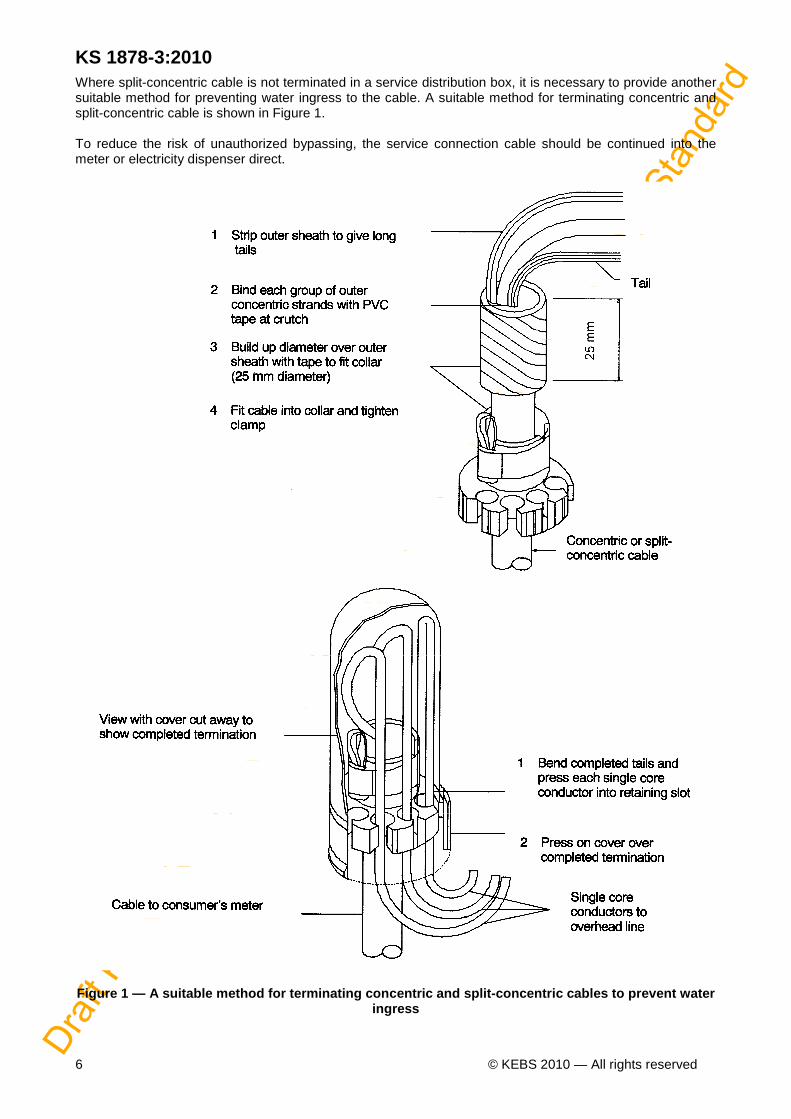
Where split-concentric cable is not terminated in a service distribution box, it is necessary to provide another suitable method for preventing water ingress to the cable. A suitable method for terminating concentric and split-concentric cable is shown in Figure 1. To reduce the risk of unauthorized bypassing, the service connection cable should be continued into the meter or electricity dispenser direct.
Figure 1 — A suitable method for terminating concen tric and split-concentric cables to prevent water ingress

Draf
t Ken
ya S
tand
ard
for B
allot
ing —
Not
to b
e Ci
ted
as K
enya
Sta
ndar
d
KS 1878-1:2010
© KEBS 2010 — All rights reserved 7
Depending on the operational and maintenance requirements, circuit-breakers, fuses or isolators should be provided at the pole top. Using such devices for the connection of individual service connections provides greater flexibility during operation and maintenance, although groups of up to four service connections may be connected through one device (suitably rated) to reduce the capital cost. Services should be so connected that the loads are, as far as is practicable, balanced across phases at all points along the line. 5.9.3.3 Span lengths for service connections Concentric and split-concentric cables are considered to be fully insulated cables and consequently the minimum clearances required are to prevent physical damage to the cable. These minimum clearances are given in Table 2.
Table 2 — Minimum ground clearance for service conn ections
1
2 Classification of area to be crossed
Minimum cl earance
m Main roads
5.1
Across roads in townships
4.7 Along other roads
3.0
Over private property
2.5
5.9.4 Customer metering A preferred method of metering is the use of electricity dispensers (EDs) that comply with IEC 62055-31. An alternative method is to use "conventional" credit meters that comply with IEC 62053-11 (electromechanical type) or with IEC 61036 (electronic type). Other methods that may be considered for application in very low and low consumption areas are: a) the use of electricity control units (ECUs), that combine the functions of a prepayment meter and a
ready board into one, which may be current limited at different levels; or b) current-limited circuit breakers associated with a tariff that is dependent on the rating of the circuit-
breaker. Protection of the service connection should be provided in accordance with the guidelines given in KS 1878-1. 5.10 Customer's wiring Where a customer's dwelling does not have fixed wiring, a small power distribution unit that complies with IEC 60439-3 should be installed.

Draf
t Ken
ya S
tand
ard
for B
allot
ing —
Not
to b
e Ci
ted
as K
enya
Sta
ndar
d
KS 1878-3:2010
8 © KEBS 2010 — All rights reserved
Annex A
(informative)
Inspections and tests record sheet A record sheet for each installation should be prepared as set out in the model record sheet below, where the results of inspections and tests can be recorded. Where a supply authority does not have its own record sheet, the model record sheet in this annex may be used. For an installation to pass inspection, the answer to each applicable question on the record sheet must be "Yes". Model inspections and tests record sheet
PROJECT NAME : ________________________ DISTRICT : __________________________________
PROJECT DESCRIPTION : _____________________________________________________________
CONTRACTOR : ______________________ REPRESENTATIVE : _____________________________ Company Name Name (print)
CONSULTANT : ______________________ REPRESENTATIVE : ______________________________ Company Name Name (print)
Item no.
Inspection or test description Yes No Not applicable
1 Visual inspection
1.1 Do the installation and the layout drawing correspond with each other?
1.2 In the case of MV ABC, is the radius of curvature of the bundled ABC not less than specified by the manufacturer?
aerial
2 Transformers
2.1 Is each transformer installation labelled in accordance with 5.5?
2.2 Are MV surge arresters fitted to all transformers? (see 5.2)
2.3 Are LV surge arresters fitted? (see 5.2)
2.4 Are the MV and LV surge arresters earthed?
2.5 Is each transformer tank earthed?
3 LV feeders
3.1 Are stays insulated as necessary? (see 5.7)
3.2 Is there bonding on all conductive poles in accordance with the earthing system adopted? (see KS 503-2)
3.3 Are the services balanced across phases as indicated on the layout drawing?
3.4 Are the clearances to ground and to shared services in accordance with the IEC 61865?
3.5 Have the shear heads of all insulation piercing connectors been removed?
3.6 Are end caps fitted on ABC phase cores at termination points?
3.7 Are bundles strapped with cable ties at attachment points, to avoid unravelling of the bundle?
3.8 Is the neutral earthed in accordance with the LV earthing practice adopted? (see KS 503-2)

Draf
t Ken
ya S
tand
ard
for B
allot
ing —
Not
to b
e Ci
ted
as K
enya
Sta
ndar
d
KS 1878-1:2010
© KEBS 2010 — All rights reserved 9
Item no. Inspection or test description
Yes No Not applicable
4 Service connections
4.1 Do the service cables continue into the back of the electricity dispensers?
4.2 Do all customers have an approved small distribution board, or else a certificate of compliance for their installation?
4.3 Are the customers satisfied with the positioning of the ready boards?
4.4 Is the installation in the customer’s dwelling neat and tidy?
5 Electrical tests
5.1 Insulation resistance tests
5.1.1 Disconnect the LV feeders at the transformer. With all pole-top box circuit-breakers switched off or fuses removed, use a 1 kV insulation tester to test between each phase and earth and also between phases. Take care to discharge the ABC before disconnection of megger leads. Record the readings on the record sheet. Are the results at least 1 MW between phases and at least 1 MW between phases and neutral?
5.1.2 Where applicable, have insulation tests been performed on each MV ABC feeder and the insulation resistance of each feeder recorded?
5.2 Earth resistance tests
5.2.1 Have the tests in accordance with KS 503-2 been carried out and the results recorded on the record sheet?
5.2.2 Has the physical and electrical integrity of each earthing joint and weld been verified?
5.3 Voltage and polarity tests
5.3.1 Have the phase-to-phase and phase-to-neutral voltages at the terminal poles been measured and recorded? (NB With feeder energized and pole-top circuit-breakers switched off or fuses removed.)
5.3.2 Check the polarity at the pole-top boxes by measuring the voltage: a) are voltages between phase bar(s) and earth bar approximately 230 V, not 400 V? b) are voltages between phase bar(s) and neutral bar approximately 230 V, not 400 V? c) is the voltage between neutral bar and earth bar at, or about, zero? d) is the voltage between earth bar and pole earth at, or about, zero?
NOTE After the tests, the individual pole-top box circuit-breakers can be switched on or fuses replaced and the polarity of all the installations supplied from each pole tested. The voltage level in each dwelling can also be determined. On the electrical test record sheet, confirm whether the voltage in each dwelling is within statutory limits.
INSPECTION DONE BY: ____________________________________ __________________________________ Name (print)
____________________________________ ___________________________________ Signature Date
CONTRACTOR: ____________________________________ __________________________________ Name (print)
____________________________________ ___________________________________ Signature Date
CONSULTANT: ____________________________________ ___________________________________ Name (print)
____________________________________ ____________________________________ Signature Date
Draf
t Ken
ya S
tand
ard
for B
allot
ing —
Not
to b
e Ci
ted
as K
enya
Sta
ndar
d
KS 1878-3:2010
10 © KEBS 2010 — All rights reserved
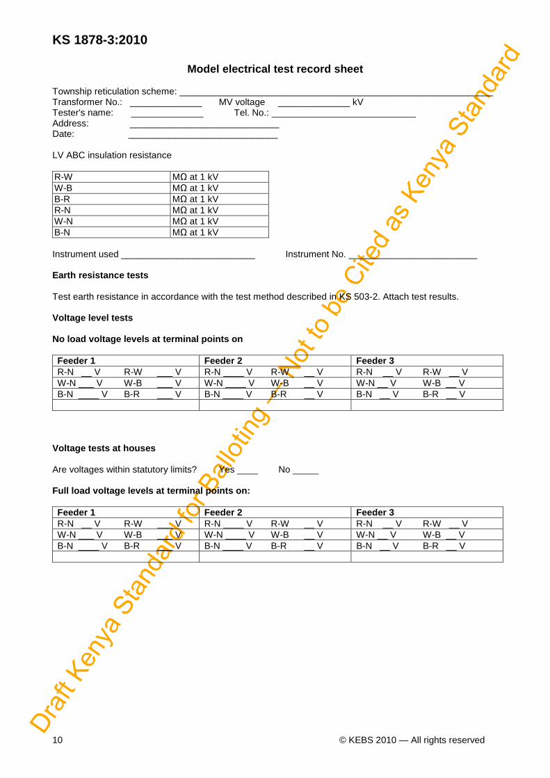
Model electrical test record sheet
Township reticulation scheme: _____________________________________________________________ Transformer No.: ______________ MV voltage ______________ kV Tester's name: ______________ Tel. No.: ____________________________ Address: _____________________________ Date: _____________________________ LV ABC insulation resistance R-W MΩ at 1 kV W-B MΩ at 1 kV B-R MΩ at 1 kV R-N MΩ at 1 kV W-N MΩ at 1 kV B-N MΩ at 1 kV Instrument used __________________________ Instrument No. _________________________ Earth resistance tests Test earth resistance in accordance with the test method described in KS 503-2. Attach test results. Voltage level tests No load voltage levels at terminal points on Feeder 1 Feeder 2 Feeder 3 R-N __ V R-W ___ V R-N ____ V R-W __ V R-N __ V R-W __ V W-N ___ V W-B ___ V W-N ____ V W-B __ V W-N __ V W-B __ V B-N ____ V B-R ___ V B-N ____ V B-R __ V B-N __ V B-R __ V
Voltage tests at houses Are voltages within statutory limits? Yes ____ No _____ Full load voltage levels at terminal points on: Feeder 1 Feeder 2 Feeder 3 R-N __ V R-W ___ V R-N ____ V R-W __ V R-N __ V R-W __ V W-N ___ V W-B ___ V W-N ____ V W-B __ V W-N __ V W-B __ V B-N ____ V B-R ___ V B-N ____ V B-R __ V B-N __ V B-R __ V

Draf
t Ken
ya S
tand
ard
for B
allot
ing —
Not
to b
e Ci
ted
as K
enya
Sta
ndar
d
KS 1878-1:2010
© KEBS 2010 — All rights reserved 11
Annex B
(informative)
Design span tables A selection of design span tables are given to assist with the design of LV feeders using one, two and three phase LV ABC. Table B.1 gives the design spans for LV ABC with three 70 mm2 phase conductor cores. Table B.2 gives the design spans for LV ABC with three 35 mm2 phase conductor cores. Table B.3 gives the design spans for LV ABC with two 35 mm2 phase conductor cores. Table B.4 gives the design spans for LV ABC with one 35 mm2 phase conductor core.

Draf
t Ken
ya S
tand
ard
for B
allot
ing —
Not
to b
e Ci
ted
as K
enya
Sta
ndar
d
KS 1878-3:2010
© KEBS 2010 — All rights reserved 12
Table B.1 — Design spans for LV ABC with three 70 m m2 phase conductor cores
1 2 3 4 5 6 7 8 9 10 11 12 Pole length m
Pole top diameter mm
Nominal span m
Weight span m
Wood pole suspension structures
Wood pole strain structures
Maximum span length
Maximum span length
Maximum span length one x three-phase m
Maximum span length two x three-phase m
One x three-phase m
Two x three-phase m
Deviation 30°
Deviation 60°
Deviation 90°
Deviation 30° Deviation 60° Deviation 90°
7 0.12 85 120 63 32 120 120 120 120 115 45 7 0.14 85 120 95 48 120 120 120 120 120 120 7 0.16 85 120 136 68 120 120 120 120 120 120 7 0.18 85 120 187 94 120 120 120 120 120 120 9 0.12 100 120 58 29 120 120 120 150 60 N/A 9 0.14 100 120 87 44 120 120 120 120 120 120 9 0.16 100 120 124 62 120 120 120 120 120 120 9 0.18 100 120 171 85 120 120 120 120 120 120 10 0.12 110 120 54 27 120 120 120 115 25 N/A 10 0.14 110 120 81 41 120 120 120 120 120 105 10 0.16 110 120 116 58 120 120 120 120 120 120 10 0.18 110 120 159 79 120 120 120 120 120 120 10 0.20 110 120 211 105 120 120 120 120 120 120 11 0.12 120 120 50 25 120 120 120 85 N/A N/A 11 0.14 120 120 76 38 120 120 120 120 120 50 11 0.16 120 120 108 54 120 120 120 120 120 120 11 0.18 120 120 148 74 120 120 120 120 120 120 11 0.20 120 120 196 98 120 120 120 120 120 120

Draf
t Ken
ya S
tand
ard
for B
allot
ing —
Not
to b
e Ci
ted
as K
enya
Sta
ndar
d
KS 1878-1:2010
© KEBS 2010 — All rights reserved 13
Table B.2 — Design spans for LV ABC with three 35 m m2 phase conductor cores
1 2 3 4 5 6 7 8 9 10 11 12 Pole length m
Pole top diameter mm
Nominal span m
Weight span m
Wood pole suspension structures
Wood pole strain structures
Maximum span length
Maximum span length
Maximum span length one x three-phase m
Maximum span length two x three-phase m
One x three-phase m
Two x three-phase m
Deviation 30° Deviation 60° Deviation 90°
Deviation 30°
Deviation 60° Deviation 90°
7 0.12 90 210 78 39 210 210 210 210 140 55 7 0.14 90 210 118 59 210 210 210 210 210 210 7 0.16 90 210 168 84 210 210 210 210 210 210 7 0.18 90 210 231 116 210 210 210 210 210 210 9 0.12 100 210 71 36 210 210 210 185 75 N/A 9 0.14 100 210 108 54 210 210 210 210 210 205 9 0.16 100 210 154 77 210 210 210 210 210 210 9 0.18 100 210 211 105 210 210 210 210 210 210 10 0.12 110 210 67 33 210 210 200 140 35 N/A 10 0.14 110 210 100 50 210 210 210 210 210 130 10 0.16 110 210 143 72 210 210 210 210 210 210 10 0.18 110 210 196 98 210 210 210 210 210 210 10 0.20 110 210 261 130 210 210 210 210 210 210 11 0.12 120 210 62 31 210 215 125 105 N/A N/A 11 0.14 120 210 94 47 210 210 210 210 155 65 11 0.16 120 210 134 67 210 210 210 210 210 210 11 0.18 120 210 183 92 210 210 210 210 210 210 11 0.20 120 210 242 121 210 210 210 210 210 210

Draf
t Ken
ya S
tand
ard
for B
allot
ing —
Not
to b
e Ci
ted
as K
enya
Sta
ndar
d
KS 1878-3:2010
14 © KEBS 2010 — All rights reserved
Table B.3 — Design spans for LV ABC with two 35 mm 2 phase conductor cores
1 2 3 4 5 6 7 8 9 10 11 12 Pole length m
Pole top diameter mm
Nominal span m
Weight span m
Wood pole suspension structures
Wood pole strain structures
Maximum span length
Maximum span length
Maximum span length one x dual-phase m
Maximum span length two x dual-phase m
One x dual-phase m
Two x dual-phase m
Deviation 30°
Deviation 60°
Deviation 90° Deviation 30° Deviation 60° Deviation 90°
7 0.12 110 280 103 51 280 280 280 280 190 70 7 0.14 110 280 155 78 280 280 280 280 280 280 7 0.16 110 280 222 111 280 280 280 280 280 280 7 0.18 110 280 305 153 280 280 280 280 280 280 9 0.12 125 280 94 47 280 280 280 240 100 N/A 9 0.14 125 280 142 71 280 280 280 280 280 270 9 0.16 125 280 203 102 280 280 280 280 280 280 9 0.18 125 280 279 139 280 280 280 280 280 280 10 0.12 140 280 88 44 280 280 260 185 45 N/A 10 0.14 140 280 133 66 280 280 280 280 280 170 10 0.16 140 280 189 95 280 280 280 280 280 280 10 0.18 140 280 259 130 280 280 280 280 280 280 10 0.20 140 280 344 172 280 280 280 280 280 280 11 0.12 150 280 82 41 280 280 165 135 N/A N/A 11 0.14 150 280 124 62 280 280 280 280 205 85 11 0.16 150 280 177 88 280 280 280 280 280 280 11 0.18 150 280 242 121 280 280 280 280 280 280 11 0.20 150 280 320 160 280 280 280 280 280 280
Draf
t Ken
ya S
tand
ard
for B
allot
ing —
Not
to b
e Ci
ted
as K
enya
Sta
ndar
d
KS 1878-1:2010
© KEBS 2010 — All rights reserved 15
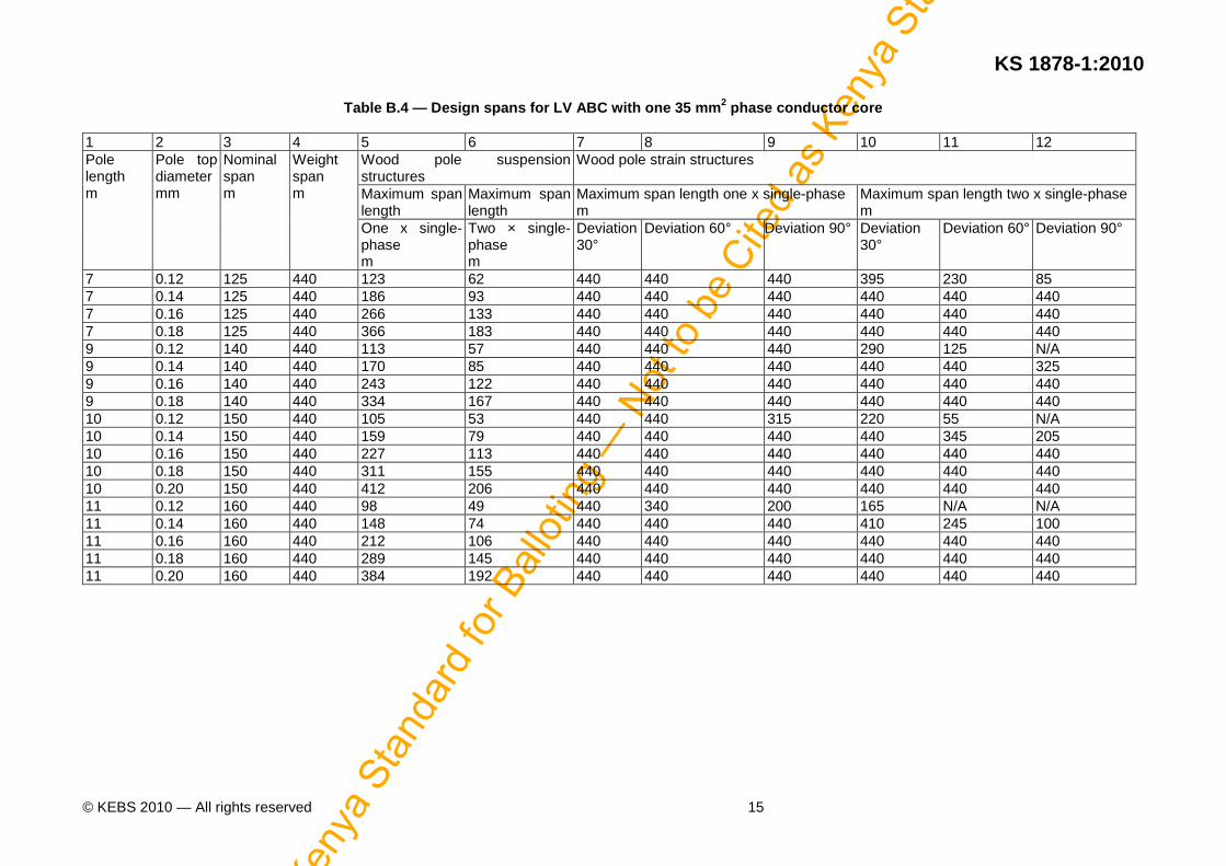
Table B.4 — Design spans for LV ABC with one 35 mm 2 phase conductor core
1 2 3 4 5 6 7 8 9 10 11 12 Pole length m
Pole top diameter mm
Nominal span m
Weight span m
Wood pole suspension structures
Wood pole strain structures
Maximum span length
Maximum span length
Maximum span length one x single-phase m
Maximum span length two x single-phase m
One x single-phase m
Two × single-phase m
Deviation 30°
Deviation 60° Deviation 90°
Deviation 30°
Deviation 60°
Deviation 90°
7 0.12 125 440 123 62 440 440 440 395 230 85 7 0.14 125 440 186 93 440 440 440 440 440 440 7 0.16 125 440 266 133 440 440 440 440 440 440 7 0.18 125 440 366 183 440 440 440 440 440 440 9 0.12 140 440 113 57 440 440 440 290 125 N/A 9 0.14 140 440 170 85 440 440 440 440 440 325 9 0.16 140 440 243 122 440 440 440 440 440 440 9 0.18 140 440 334 167 440 440 440 440 440 440 10 0.12 150 440 105 53 440 440 315 220 55 N/A 10 0.14 150 440 159 79 440 440 440 440 345 205 10 0.16 150 440 227 113 440 440 440 440 440 440 10 0.18 150 440 311 155 440 440 440 440 440 440 10 0.20 150 440 412 206 440 440 440 440 440 440 11 0.12 160 440 98 49 440 340 200 165 N/A N/A 11 0.14 160 440 148 74 440 440 440 410 245 100 11 0.16 160 440 212 106 440 440 440 440 440 440 11 0.18 160 440 289 145 440 440 440 440 440 440 11 0.20 160 440 384 192 440 440 440 440 440 440

Draf
t Ken
ya S
tand
ard
for B
allot
ing —
Not
to b
e Ci
ted
as K
enya
Sta
ndar
d
KS 1878-3:2010
© KEBS 2010 — All rights reserved 16
Annex C
(informative)
Use of design evaluation indicators C.1 Introduction
With large numbers of concurrent electrification projects, it is often impossible to check the designs in detail. The checking of the design detail is often very time consuming and in certain cases checking can take as long as did doing the design from scratch.
Indicators are therefore used for a quick evaluation of the design from a technical point of view. It might be possible to have an acceptable design that should have resulted in a lower cost per connection. Likewise, if the cost per connection is excessive, it might be due not to the design but to the layout, terrain or technology used. C.2 Types of indicators Indicators can be divided into two broad categories, namely financial and technical. Financial indicators include the cost per connection and cost of materials. Technical indicators generally detail the utilization of material. This annex deals with technical indicators. C.3 Nature of LV designs in rural areas Designs in rural areas generally use overhead MV and LV lines. These are therefore power lines and the line design methodology can be applied. The layout and density of the area to be supplied will also play a part in the value of the indicators. This means that indicators should be used in conjunction with one another rather than in isolation. It is important to note that indicators such as design indicators can never be rigidly applied and target values assigned to indicators can only serve as guidance. Each design project is unique and as such the optimum value of the indicator will be unique. The targets set are thus levels for which, if they are not reached, an explanation should be given to the person reviewing the design. C.4 Indicators to use Many indicators can be used. They are generally broken down into the different sections described in C.7. C.5 Description of project The project description will include the terrain, location, and type of dwelling to be connected as well as the material used in construction of the dwellings, for example, mud, corrugated iron or wood. The density can be measured in terms of connections per kilometre of MV and LV line used in the design, or the number of connections per square kilometre. C.6 Use of material The indicators for material show how efficiently the material has been used. They include indicators such as span length, conductor type, length of service connection per stand, number of poles used next to the dwelling to support the service cable, number of poles of 11 m, 9 m, 7 m or 4.5 m used as well as the number of transformers and the size of transformers. The transformer rating and number of connections can give an idea of the ADMD used in the design of the area to be supplied. The utilization of the transformers can also be determined, by considering the number of connections supplied from each transformer. C.7 Analysis of indicators
Knowledge of design of the area to be supplied as well as knowledge of lines are required for the effective analysis of indicators. An example for the values and targets for indicators applicable to a particular project follows:
Draf
t Ken
ya S
tand
ard
for B
allot
ing —
Not
to b
e Ci
ted
as K
enya
Sta
ndar
d
KS 1878-1:2010
© KEBS 2010 — All rights reserved 17
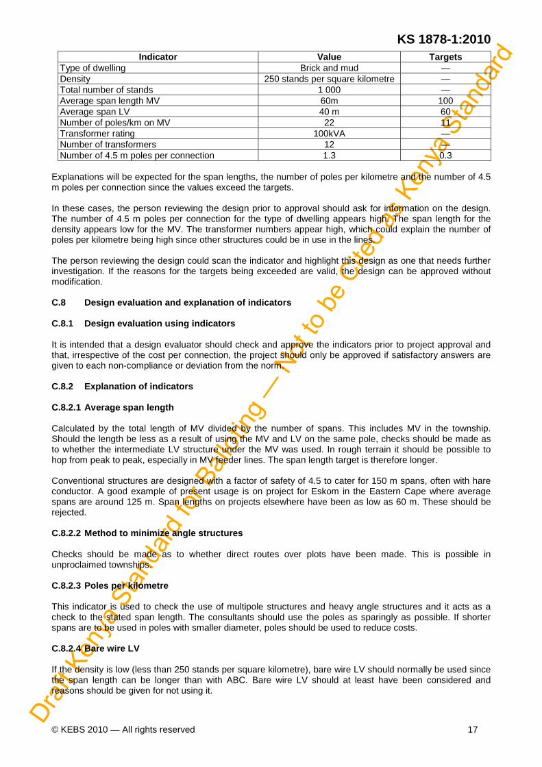
Indicator Value Targets Type of dwelling Brick and mud — Density 250 stands per square kilometre — Total number of stands 1 000 — Average span length MV 60m 100 Average span LV 40 m 60 Number of poles/km on MV 22 11 Transformer rating 100kVA — Number of transformers 12 — Number of 4.5 m poles per connection 1.3 0.3
Explanations will be expected for the span lengths, the number of poles per kilometre and the number of 4.5 m poles per connection since the values exceed the targets. In these cases, the person reviewing the design prior to approval should ask for information on the design. The number of 4.5 m poles per connection for the type of dwelling appears high. The span length for the density appears low for the MV. The transformer numbers appear high, which could explain the number of poles per kilometre being high since other structures could be in use in the lines. The person reviewing the design could scan the indicator and highlight this design as one that needs further investigation. If the reasons for the targets being exceeded are valid, the design can be approved without modification. C.8 Design evaluation and explanation of indicators C.8.1 Design evaluation using indicators It is intended that a design evaluator should check and approve the indicators prior to project approval and that, irrespective of the cost per connection, the project should only be approved if satisfactory answers are given to each non-compliance or deviation from the norm. C.8.2 Explanation of indicators C.8.2.1 Average span length Calculated by the total length of MV divided by the number of spans. This includes MV in the township. Should the length be less as a result of using the MV and LV on the same pole, checks should be made as to whether the intermediate LV structure under the MV was used. In rough terrain it should be possible to hop from peak to peak, especially in MV feeder lines. The span length target is therefore longer. Conventional structures are designed with a factor of safety of 4.5 to cater for 150 m spans, often with hare conductor. A good example of present usage is on project for Eskom in the Eastern Cape where average spans are around 125 m. Span lengths on projects elsewhere have been as low as 60 m. These should be rejected. C.8.2.2 Method to minimize angle structures Checks should be made as to whether direct routes over plots have been made. This is possible in unproclaimed townships. C.8.2.3 Poles per kilometre This indicator is used to check the use of multipole structures and heavy angle structures and it acts as a check to the stated span length. The consultants should use the poles as sparingly as possible. If shorter spans are to be used in poles with smaller diameter, poles should be used to reduce costs. C.8.2.4 Bare wire LV If the density is low (less than 250 stands per square kilometre), bare wire LV should normally be used since the span length can be longer than with ABC. Bare wire LV should at least have been considered and reasons should be given for not using it.
Draf
t Ken
ya S
tand
ard
for B
allot
ing —
Not
to b
e Ci
ted
as K
enya
Sta
ndar
d
KS 1878-3:2010
18 © KEBS 2010 — All rights reserved
C.8.2.5 Average span length ABC The average span length should be at least 60 m. At present it is apparent that certain designs are done on CAD machines with poles being spaced at stand boundaries. This has resulted in the past in spans of around 30 m. Mid span tap-offs, with stubby pole supports if necessary, can be used. C.8.2.6 Average utilization of angle structures The 150 m span length capability of angle structures is rarely, if ever, utilized. This means that angle structures, which cost around R4 000 each, are in general, under-utilized. The aim of this indicator is to ensure the angle structure is selected on the basis of its actual capability rather than the angle of deviation it can take at 150 m spans. If the angle is 45° and th e span lengths on either side are 75 m, an angle structure capable of around 22.5° at 150 m spans can be used. Obviously the closest standard angle is to be used. With this approach it is expected that the utilization will increase from around 20 % or 30 % to around 60 %. All calculations should be submitted on request. C.8.2.7 Total transformer capacity/number of connec tions ratio The total transformer capacity per number of connections ratio is used to check whether the transformer capacity suits the stated design ADMD. The design ADMD should be around 0.6 kVA for LV and should not exceed 1 kVA for MV. C.8.2.8 Material cost as portion of total The material cost should be around 60 % of the total cost. If this indicator is below this figure the cost per connection will increase drastically and will not be contained by reduction in material due to good design and layout methods. C.8.2.9 Kicker poles (4 m concrete or 4.5 m wood) p er stand The number of "kicker" poles should be low in high-density areas where the houses are generally of sounder construction than in rural areas. If the length of service connection cable is also small the need for these poles should reduce. Every pole used represents an increase of R200 per connection. A ratio of 0.3 kicker poles per stand should not be exceeded. C.8.2.10 LV poles per stand This indicator is used to eliminate the positioning of poles at every stand boundary. In very low density areas it might be possible that the number of LV poles per stand increases to around 0.6. C.8.2.11 Poles used The number of poles used is a breakdown to establish the use of intermediate LV poles (7 m or 9 m), the use of kicker poles (4 m concrete or 4,5 m wood) and the use of large poles for increased span length (above 9 m). This indicator should be used as an overall check of the preceding indicators. C.8.2.12 Average length of service connection cable In high-density areas the average length of service connection cables should be as high as possible to reduce pole top boxes. In low-density areas longer lengths with few connections per pole top might be acceptable. This indicator should be read in conjunction with the density and the number of connections per pole top. C.8.2.13 Number of connections per pole top In high-density areas the number of connection per pole top should be around 6 to 8, in lower density areas a figure of 4 or 2 could be acceptable. C.8.2.14 Single-phase as a ratio to three-phase This indicator is more important in the lower density areas. Single-phase should be considered as a first option and reasons given if it is rejected.

Draf
t Ken
ya S
tand
ard
for B
allot
ing —
Not
to b
e Ci
ted
as K
enya
Sta
ndar
d
KS 1878-1:2010
© KEBS 2010 — All rights reserved 19
Model form for design evaluation indicators
Stand size: __________________ Connections per square kilometre: ________________________ Total number of stands: __________ Type of dwelling: __________________________________ Item
Value/ method
Reasons for non -compliance (where applicable) Attach separate sheet if necessary
Average MV span length (m) (100 m min, 120 m on rough terrain)
Methods to minimize angle structures (e.g. use of direct routes)
Poles per km of MV line (max 10) (total MV poles/total km MV line)
Bare wire LV as percentage of total LV
Average span length ABC (min 60 m)
Average utilization of angle structures (50 % min, average 60 %). This is the ratio of mechanical loading to which the structure is subjected, to the mechanical capacity of the structure
Total transformer capacity/number of connections installed (target 0.6)
ADMD designed for (initial - up to 5 years) LV – 0.6 kVA # MV – 1.0 kVA
Material cost as a portion of total (labour, transport, materials, overhead and interest during construction) cost (min 60 %)
4 m or 4.5 m poles per stand (max 0.2)
LV poles per stand (max 0.33)
Number of 4 m or 4.5 m poles Number of 7 m poles Number of poles 9 m and longer
Average length of service connection cable per stand (min 30 m)
Connections per pole (min 6). If not possible owing to remote areas, provide details in last column
Ratio of single-phase km/three-phase km (min MV 0.5 LV 0.5)
#These indicators are based on experience with newly electrified areas that do not have ready access to running water and that economically are unable to sustain a higher demand. They therefore fall into the 'Very low" consumption category. For further guidance on selection of design ADMD see KS 1878-1.


![Vaticanism Unmasked [1878]](https://img.pdfslide.us/doc/110x75/577cd0ed1a28ab9e7893488a/vaticanism-unmasked-1878.jpg)