Embed Size (px)
Citation preview
A Decentralised, Autonomous, and Congestion-aware Thermal Monitoring Infrastructure
for Photonic Network-on-Chip
Wolfgang BUter, Yanqiu Huang, Daniel Gregorek, Alberto Garcia-Ortiz Institute of Electrodynamics and Microelectronics (lTEM.ids), University of Bremen
{bueter, huang, gregorek, agarcia} @ids.uni-bremen.de
Abstract-Optical network-on-chips (oNoCs) are a promising candidate to replace electrical NoCs in many-core systems. Nanophotonic components provide high bandwidth and short transmission delay but they are very sensitive to the temperature. Temperature gradients are typically found on many-core systems. The precise reconstruction of the core's temperature and the prediction of its evolution are an inevitable requirement for an effective thermal management in oNoCs. In this work we present the first distributed and autonomous thermal monitoring infrastructure for oNoCs. It copes with the intrinsic temperature sensor's noise, provides accurate thermal predictions, and requires low communication overhead. Our approach combines Kalman filters, linear predictors, local data and global transmission to achieve an efficient implementation. The work reports a thorough analysis at the gate-level of the area overhead incurred by the communication and computation sub-modules. It shows the practicability of the approach. Further, experimental results for a 16-core SoC demonstrate that our prediction model is able to reduce by more than 92 % the communication requirements of the monitoring infrastructure.
Keywords-NoC, reconfigurable NoC, Kalman Filter, thermal management, oNoC, SoC
I. INTRODUCTION
A major challenge for the system architects is the demanding on-chip bandwidth requirements of modern manycore architectures. A promising solution to face this problem is on-chip optical conununication using silicon-compatible nanophotonic interconnects. Among the different technological possibilities, micro-ring resonators (MRR) made of silicon oxide [1], [2] appear as a promising approach: they are compatible with CMOS process technology, have a reduced footprint, and allow to control the on-chip optical signals very efficiently.
The potential of the nano-photonic is pushing the research on electrical many-core systems enhanced with an optical infrastructure. Numerous nano-photonic on-chip topologies have been already reported using either static communication topologies (mainly a ring or a crossbar), or dynamic communication topologies like optical Network-on-Chip (oNoC). They outperform the electrical-only architectures on performance, energy consumption, and scalability by several orders of magnitude. For example, the torus optical interconnects presented in [3] provides a low-delay data transfer and an extreme high end-to-end bandwidth.
However, nano-photonic NoCs bring new challenges like thermal sensitivity, which is a major concern [4], [5], [6], [7]. 978-1-4673-7942-7/15/$31.00 ©2015 IEEE
Temperature fluctuation causes a shift in the resonance frequency of the MRR leading the resonator to respond in a different frequency; then, data can be corrupted during the transmission. Thermal compensation is possible, but increases the energy consumption: the optical modulator with the best thermal stability currently reported in [4] can compensate a thermal drift of 7.5°C temperature but increases its energy consumption by 25%. Further on, thermal gradients worsen drastically the reliability and performance of photonic NoCs [8]. Thermal aware techniques for oNoCs are unavoidable.
Several static [5] and dynamic [6], [7] thermal-aware design techniques for nano-photonic systems have been already proposed. For example, a many-core system is designed by placing its internal components in an appropriate position according to the expected temperatures to minimise hot-spots [5]. This temperature-aware floorplanning methodology requires precise intra-chip temperature information, as provided by thermal simulators like HotSpot [6]. This approach is static (i.e., performed at design time) and doesn't take the multiple operation conditions of a typical many-core system into account. This rigidity can be reduced by a task allocation algorithm that minimises the temperature gradients of the MRR among the many-core chip [9]. Alternatively, a thermal aware routing algorithm, as the multi-level approach described in [7], can be used to minimise the temperature gradients between the MRR involved in the optical communication. Although the thermal-aware design techniques differ in accuracy, performance-loss, and applicability for many-core NoCs, they have a COlmnon key feature: a precise knowledge of the temperature in the chip is needed at run-time.
Indirect temperature estimation using execution-statistics is possible. For example, the performance counters of an Intel processor can produce estimates of the overall chip temperature with a typical accuracy of 5% at 70°C [lO]. Nevertheless, direct temperature sensors are preferred; they provide higher spacial resolution, robustness and accuracy. On-chip temperature-sensors using electrical transistors are commonly used in many-core systems nowadays. Its number should be carefully limited since they are relatively large and energy inefficient [11], [12]. Alternatively, in nano-photonic applications a MRR can be used as a temperature-sensor [13]. This approach allows to integrate multiple sensors on-chip close to the nano-photonic switches. Both classical and MRRbased sensors have relatively low sensitivity and high noise that need to be compensated with data processing. The problem is specially challenging for nano-photonic applications, which
require a high spatial resolution (approx. router-to router distance) and high accuracy (less than one degree).
Temperature de-noising and estimation at run-time for purely electrical many-core system is being intensively investigated [11], [12]. A filter based on an ARX-like model and distributed algorithm can clean the output noise of the sensors in a purely electrical many-core system [11]. Kalman jilters [14] are another interesting commonly used alternative for temperature de-noising and prediction [12]. However, the accuracy and scalability of those solutions is insufficient in context of oNoC.
Therefore, there is an urgent need for a thermal monitoring infrastructure with the accuracy and scalability demanded by photonic networks-on-chip. We address this problem here. Specifically, to solve the scalability requirements, we employ a decentralised and autonomous net of dedicated managers, similar to the one proposed in [15] to address the configurationmanagement in configurable optical networks. To solve the accuracy requirements, to reduce the volume of transmitted temperature data, and hence to improve scalability, we adapt the PKF technique [16] which is initially developed for Wireless-Sensor-Networks with Kalman jilter, to on-chip applications.
The rest of the paper is organised as follows: First we introduce the required background material regarding the decentralised control of oNocs (Sec. II) and temperature estimation with Kalman jilter (Sec. III). Afterwards we describe the core of our work, the thermal monitoring infrastructure. Finally we validate our approach; firstly the algorithm (Sec. V) and then the hardware (Sec. VI).
II. BACKGROUND: DECENTR ALlSED CONTROL OF oNoCs
The complexity of path management in optical interconnect architectures scales-up with the network size; manycore systems interconnected with a nano-photonic network can have more than 256 cores. To address this problem, a decentralised solution can be used [15]. The key idea is to distribute dedicated modules, called Distributed Channel Manager (DCMs), that perform the management of the circuitswitched channels autonomously. The strategy allows to extend a general electrical NoC with the infrastructure required to manage optical interconnect architectures.
The scalability issues of thermal monitoring and path management are similar. We exploit this similarity by adapting the DCM approach to create a decentralised and autonomous thermal monitoring system. To be self-contained, we summarise the relevant aspects of DCM in the next paragraphs.
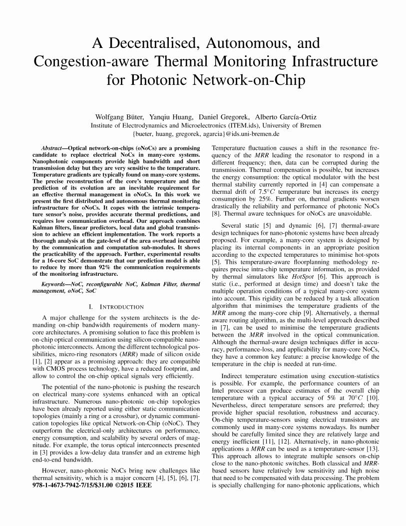
The structure of the extended network with the DCMs is illustrated in Fig. 1. Each DCM is inserted between a Processing Element (PE) and the local port of a packet-based router (pkt router) so that the communication to and from the PE is undisturbed. With this design strategy the control infrastructure can be added without needing drastic changes in the electric NoC router. The DCMs manage the optical switches in the photonic layer, the so called photonic switching elements (PSE). These PSEs build the parallel circuit-switched network which is configured autonomously by the DCM. Furthermore, there is no need to connect a complete DCM
to every router; the topologies of the basic and the optical networks can be selected independently. This feature allows an increasing flexibility, which is essential for oNoCs.
Figure l. Generic packet-based network extended with a Distributed Channel Manager (DCM) infrastructure (left) and Temperature Mapper (TM) infrastructure (right).
The operation of the DCM layer is simple. When the application running at the PE requires a new (circuit-switching) path, it sends a configuration message to a DCM. The exact path-topology can be decided by the PE at run-time using the latest network-information available. The DCM that receives the request handles the configuration of all the switches involved by sending parallel messages to the subsequently needed DCMs. Every addressed DCM confirms or denies the request autonomously. Finally, the responses are combined into a single message (i.e., ACKINACK) which is sent to the PE. As an additional feature, the switches can be deconfigured automatically if the path cannot be acknowledged. Every PE can create a new path independently and simultaneously; the DCM structure ensures the consistency of the paths.
The internal architecture of the DCM module is divided into two sub-modules, the DCMC and the DCMD, which can be implemented independently. The DCMD is responsible for the data transfer as well as the (potential) synchronisation of different clock domains between circuit-switched and packetswitched NoCs. The DCMC is responsible for detection, extraction and processing of the configuration messages. It operates as a kind of bypass which captures the configuration messages; therefore, the router does not need to be modified. Parts of the configuration messages are stored in the DCMC to control the switches. Moreover, the results of the configurationrequest evaluation are generated in the answer-generator. The DCMC is authorised to interrupt a PE's data transfer and replace the current transfer with its own data. A combinational function verifies if the received configuration is compatible to the current configuration. if it is, a new control signal for the switch is generated. Additionally, the information to configure the switch is stored and a response is generated. To send the reply, a potentially active transfer of the PE is interrupted or stopped during the transmission time of the message. With this internal structure and functionality, the DCM architecture manages the photonic switches decentralised and autonomously.
III. BACKGROUND: TEMPERATURE ESTIMATION AND
COMPRESSION USING KALMAN FILTERS
The internal temperature of a chip can be modelled as a linear dynamic system with hidden states [11], [12]; further

on, those internal states can be estimated by a series of observations which are usually corrupted by noise. Noise filtering and optimal estimation are the goals of the Kalman Filter (KF) [14].
A key observation of this paper is that some of the ideas and approaches initially proposed for data compression in wireless sensor networks can be adapted for distributed on-chip thermal monitoring. Among the Kalman-based techniques, PKF [16] is preferred since it reduces not only the communication volume (i.e., the payload), but also the number of required messages. To be self-contained, we summaries the relevant aspects of Kalman filter and PKF in the next subsections following [16].
A. Kalman Filter and the Related errors
In order to obtain an accurate estimation of the system state, a KF combines the estimate from the previous time-step with the current noisy measurement to produce an improved estimate of the current state. KF is a recursive algorithm that guaranties the minimum mean square error of the estimation for a system with Gaussian noise.
In the framework of KF, the true state Xk of the system at time k is assumed to evolve from the state at time (k - 1).
Xk = A . Xk-l + B . Uk + Wk (1)
where A is the transition matrix; B is the control-input matrix; Uk is the control input vector; Wk rv N(O, Q) accounts for the inexactitudes of the model and has covariance Q. The observation Zk of the true state at time k is mapped from Xk by the observation matrix H and corrupted with a zero mean white Gaussian noise Vk.
Zk = H· Xk + Vk
where Vk rv N(O, R) has the covariance R.
(2)
The process of the KF can be separated into two steps: predict and update. In the predict phase, the state estimate of the previous time step Xk-l is used to generate an a priori estimate of the current state x I: .
xl: = A· Xk-l + B . Uk (3)
Let el: = xl: - Xk denote the error between this a priori estimate and the true state. The uncertainty of this prediction is measured by the covariance of the error. It is calculated by:
Pk=E{el:.eI:T}=A.Pk_l·AT+Q (4)
where Pk-1 is the a posteriori covariance of the last time step. It will be discussed in more detail later in this section
In the update phase, the current measurement Zk is incorporated into the a priori prediction to produce an improved a posteriori state estimate Xk. For convenience, we call it optimal value in the following. The basic idea behind this phase is to use a weighted average, with more weight K k being given to the a priori estimate with higher certainty. The weight, also known as Kalman gain, satisfies:
The updated estimate of the system lies between the predicted and measured state, and is given by:
(6)
Let ek = Xk - Xk denote the error of this optimal estimate. Its covariance indicates the uncertainty of the final estimate, which is:
Typically, after several steps the KF enters a steady state, where the Kalman gain and the covariance converge to constant values: Kk---7oo = K, Pk---700 = P-, Pk---700 = P. Then only (3) and (6) are needed to predict the future state.
B. Data prediction combined with Kalman filter (P KF)
The data prediction combined with Kalman Filter (PKF) approach applies to a cluster-based WSN where a leaf node has to transmit some physical magnitudes to a cluster head. Its main idea is to skip the communication between a leaf node and its cluster head at a time step if the cluster head is able to predict the current data of the leaf node with a tolerable error using the previous received data. PKF assumes that the Kalman model parameters of the physical magnitude are known by both the leaf node and the cluster head. Our thermal monitoring infrastructure applies the PKF concept for temperature data but it uses distributed on-chip blocks instead of sensor motes. Below, the terms Master and Slave are introduced in this proposed on-chip system, instead of leaf node and cluster head.
Since the observations of the Slave are usually corrupted by noise, each node is required to firstly execute a KF to filter out noise and produce optimal values. In order to reduce the communication energy cost and guarantee the data quality, Huang et. al [16] proposed to establish a KF-based predictor for both the Slave and the Master. The Master uses it to predict the optimal value of the Slave. The Slave follows the prediction of the Master with this predictor and compares the forecast with its optimal value. Only if the prediction error exceeds the threshold, the current optimal value is transmitted to the Master. The Master runs an individual predictor for each Slave. This requires the predictor to be as simple as possible. The precise algorithm (see algo. 1 and algo. 2) is as follows.
The Slave firstly performs a KF to obtain the optimal values using (3)-(7). The simple predictor implemented in the Master is consistent with the a priori estimate model (3) of the KF. It is given by:
(8)
The prediction error is denoted as Ck = H . (Xk - Xk). It is the difference between the predicted observation, H . Xk, and the a posteriori estimated observation, H . Xk. By synchronously executing the same predictor, the nodes calculates the error Ck. When it exceeds a given threshold T, the Kalman optimal value is transmitted. Thus, the final reconstructed value of the Master is Zk = H . Xk, where
(9)
The threshold T depends on the accuracy requirement of a specific application. Observe that this scheme guarantees a maximum error bound.
Algorithm 1 PKF algorithm for the Slave
1: Initialize Xl, �A and Xl 2: for each Zk do 3: Calculate X-,;;, Pi; using (3) and (4) 4: Calculate Xb Kb Pk using (6)-(7) 5: Xk +- A . Xk-l + B . Uk 6: Ek +- H . (Xk - Xk) 7: if Ek > T then 8: Send Xk 9: Xk +- Xk
10: end if 11: end for
Algorithm 2 PKF algorithm for the Master
1: Initialize Xl 2: for each prediction time do 3: if update Xk is available then 4: Xk +- Xk 5: else 6: Xk +- A· Xk-l + B . Uk 7: end if 8: Zk = H . Xk 9: end for
IV. THERMAL MONITORING INFR ASTRUCTURE
A high temperature difference between the source and sink of an optical link may prohibit a successful communication. The functionality of the proposed thermal monitoring infrastructure for photonic network-on-chip is double. Firstly, it allows the accurate reconstruction and prediction of the real temperature of a local sensor using an accurate Kalman-based estimation. Secondly, it allows a replication in a given Master node of the temperature of another possibly far-located node. This temperature-replication is required by some thermalaware approaches, e.g. by thermal-depended routing [7].
This section describes our proposed architecture to achieve this double functionality. Firstly, we describe the overall topology and the communication strategy between a Master and a Slave node to replicate the temperature efficiently; afterwards, we describe the internal structure of temperature management nodes, the so called Temperature Mapper (TM) nodes.
A. Communication between TMs
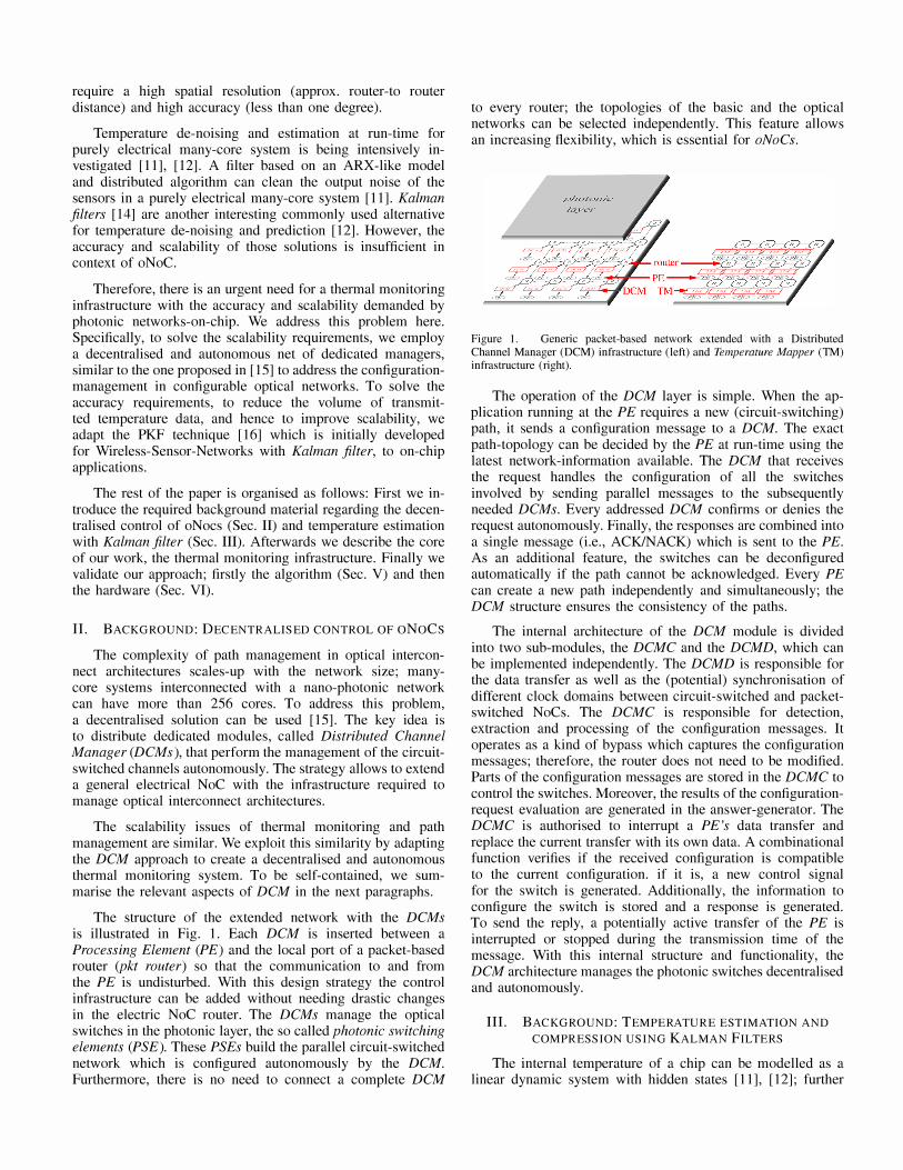
A net of dedicated TMs is implemented in a packedbased, mesh topology NoC, as described in Fig. 1. Each TM sends his own reconstructed temperature to its neighbour TM automatically when the accuracy of the locale predictor exceeds its allowed deviation. This data is named ttrace_n. The structure of the communication is depicted in Fig. 2. The Local TM (L) has access to three data streams: The power profile of the core ptrace is send from the core to the TM, the own noisy temperature own_trace is available as an extra
input signal and the above described ttrace_n is sent from the neighbours TMs. The data ptrace and ttrace_n are elements of the control input Uk as shown in the algorithm 1 and algorithm 2 of Sec. III.
Figure 2. System topology of the Temperature Mapper (TM) infrastructure illustrating the communication between TM nodes
A Master module located anywhere in the SoC can make a request to a TM for its actual temperature and it's derivation. After this request, the Slave TM sends automatically the temperature data to the Master TM when the error of the predictor exceeds its maximum allowed deviation, the threshold value. The Master TM also has a prediction of the temperature. Therefore, the implemented net of TMs constitute the Slave modules whereas any predictor (as a PE or TM) can work as a Master.
The message transfer between Master and Slave described above decreases by the implemented PKF algorithm; the control input Uk has an impact on the quality of temperature reconstruction, and the transfer rate of the messages. This is discussed in more detail in Sec. V.
B. The Thermal-Map module
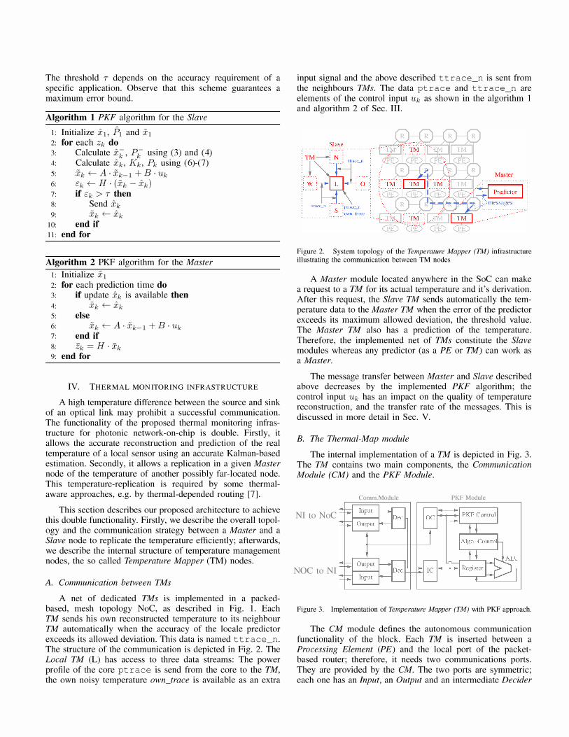
The internal implementation of a TM is depicted in Fig. 3. The TM contains two main components, the Communication Module (CM) and the PKF Module.
Comm.Module PKF Module
NI to NoC
NOC to NI
Figure 3. Implementation of Temperature Mapper (TM) with PKF approach.
The CM module defines the autonomous conununication functionality of the block. Each TM is inserted between a Processing Element (PE) and the local port of the packetbased router; therefore, it needs two communications ports. They are provided by the CM. The two ports are synunetric; each one has an Input, an Output and an intermediate Decider
module. The Input module contains a buffer for two virtual channels and a controller, and it conununicates with the Output module via a handshake protocol. The Output contains a Pipeline stage, a Credit Management and a Controller. The credit management unit ensures that the inserted TM does not alter the consistency of the credit-based flow control used in the packed-based NoC. Every data needs two clock cycles to move through the CM. The Decider filters the data messages for the TM. There are two main data streams in the data messages: the power of the closest core (the ptrace), and the temperature and it's derivation from the the neighbouring TM (the ttrace_n). The CM captures and redirects these messages to the PKF Module.
The PKF Module contains an Input Controller (IC), an Output Controller (OC), Registers for data, an ALU, the Algorithm Control and the PKF Control. The IC receives the data messages from the Decider, and extracts the payload information of the packet. This fresh data updates the data in Registers and allows the described KF iteration.
The KF algorithm is intricate. Our design strategy is to minimise area. For this purpose the ALU includes only a compact Multiply-Accumulate unit (MAC) and an area efficient Reciprocal Unit as a PE inside TM. The unit has been implemented using multi-cycle paths with the target frequency of 1 GHz. These multi-cycle values are technology dependent. For example, in a 65nm technology, it requires four clock cycles for multiplication and/or addition and 15 clock cycles for calculating the reciprocal value.
The functionality of the a posteriori estimate of KF is implemented in the Algorithm Control. Every necessary data from the PKF algorithm are saved in the registers. The Algorithm Control performs one operation at a time and even if the execution of the implemented algorithm needs 124 up to 156 clock cycles, it is still in the nanosecond range, and thus for thermal balancing processes is sufficiently fast. The different numbers of clock cycles is caused by the control input Uk, either it is implemented or not in Algorithm Control.
The unit P KF Control decides when to send data. This is the case when the temperature data is requested from a different module or when the error of the local prediction exceeds the adjusted threshold. This request travels via the OC to corresponding Output of CM. The implementation of fixed point operations in PKF Module, has an impact on the accuracy of the P KF algorithm. This is discussed in more detail in Sec. VI.
V. EXPERIMENTAL VALIDATION: ALGORITHM ANALYSIS
This section analyses empirically the validity of the PKF algorithm for predicting on-chip thermal data in many-core nano-photonic applications. PKF is initially developed for WSN, and we need to probe its validity for our scenario. Further on, this section quantifies the impact of PKF on reducing the message volume between Slave and Master. Here we assume a precise floating point realisation. The final fixed point implementation, as well as the trade-off between accuracy and hardware complexity are discussed in the next section.
First, we create some realistic temperature traces for a many-core systems using the thermal simulator, HotSpot [6].
The tool provides realistic temperature maps of a die considering the internal floorplan and power consumption of the cores. We select the floorplan of a 16-core multiprocessor system as an illustrative example. The power traces, the ptraces, for every core reflect a complex thermal scenario with 60000 data points. We allow each core up to 40 watts peak power to accelerate the thermal balancing. Further on, we introduce random periodical low-activity refrigeration phases to provide realistic temperatures within the typical ranges found in standard systems. The model for the package is the default one in HotSpot. A batch of HotSpot thermal simulation provides the temperature profiles of each core at equidistant time intervals, the ttraces. This realistic traces are further corrupted by Gaussian random noise with variance 0.25°C2 to simulate the physical noise of the temperature sensors. The corrupted temperature values of a randomly selected central core and its four neighbours provide the experimental data for the further experiments.
The power traces, ptraces, and temperature traces, ttraces, are realistic and complex. They are depicted in Fig. 4 as a reference (only the first 3000 data points out of 60000 are shown for clarity). The temporal trend is difficult to predict and account for numerous effects. For example, let us consider the temperature in the core 5. Initially the core does not consume any power, however its temperature rises from 30°C to 34.54°C due to the effect of the neighbour cores. At the data sample 656, the power of core 5 increases abruptly to 40 Watts, which rises immediately the temperature of the neighbours.
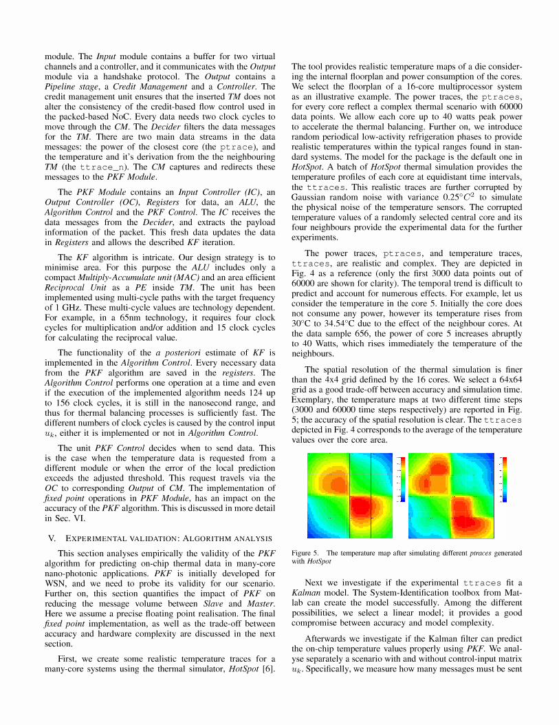
The spatial resolution of the thermal simulation is finer than the 4x4 grid defined by the 16 cores. We select a 64x64 grid as a good trade-off between accuracy and simulation time. Exemplary, the temperature maps at two different time steps (3000 and 60000 time steps respectively) are reported in Fig. 5; the accuracy of the spatial resolution is clear. The ttraces depicted in Fig. 4 corresponds to the average of the temperature values over the core area.
Figure 5. The temperature map after simulating different ptraces generated with HotSpot
Next we investigate if the experimental ttraces fit a Kalman model. The System-Identification toolbox from Matlab can create the model successfully. Among the different possibilities, we select a linear model; it provides a good compromise between accuracy and model complexity.
Afterwards we investigate if the Kalman filter can predict the on-chip temperature values properly using PKF. We analyse separately a scenario with and without control-input matrix Uk. Specifically, we measure how many messages must be sent
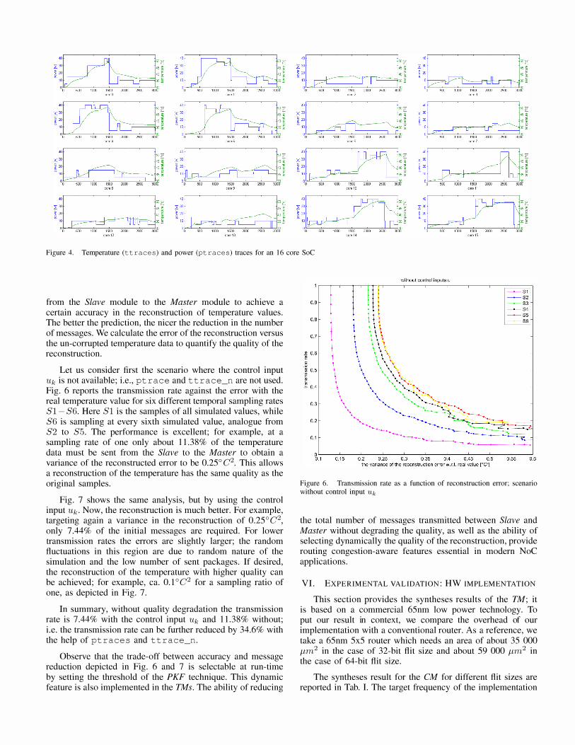
Figure 4. Temperature (ttraces) and power (ptraces) traces for an 16 core SoC
from the Slave module to the Master module to achieve a certain accuracy in the reconstruction of temperature values. The better the prediction, the nicer the reduction in the number of messages. We calculate the error of the reconstruction versus the un-corrupted temperature data to quantify the quality of the reconstruction.
Let us consider first the scenario where the control input Uk is not available; i.e., pt race and t t race_n are not used. Fig. 6 reports the transmission rate against the error with the real temperature value for six different temporal sampling rates Sl- S6. Here Sl is the samples of all simulated values, while S6 is sampling at every sixth simulated value, analogue from S2 to S5. The performance is excellent; for example, at a sampling rate of one only about 11.38% of the temperature data must be sent from the Slave to the Master to obtain a variance of the reconstructed error to be 0.25° C2. This allows a reconstruction of the temperature has the same quality as the original samples.
Fig. 7 shows the same analysis, but by using the control input Uk. Now, the reconstruction is much better. For example, targeting again a variance in the reconstruction of 0.25°C2, only 7.44% of the initial messages are required. For lower transmission rates the errors are slightly larger; the random fluctuations in this region are due to random nature of the simulation and the low number of sent packages. If desired, the reconstruction of the temperature with higher quality can be achieved; for example, ca. 0.1 ° C2 for a sampling ratio of one, as depicted in Fig. 7.
In summary, without quality degradation the transmission rate is 7.44% with the control input Uk and 1l.38% without; i.e. the transmission rate can be further reduced by 34.6% with the help of ptraces and ttrace_n.
Observe that the trade-off between accuracy and message reduction depicted in Fig. 6 and 7 is selectable at run-time by setting the threshold of the PKF technique. This dynamic feature is also implemented in the TMs. The ability of reducing
Figure 6. Transmission rate as a function of reconstruction error; scenario without control input Uk
the total number of messages transmitted between Slave and Master without degrading the quality, as well as the ability of selecting dynamically the quality of the reconstruction, provide routing congestion-aware features essential in modern NoC applications.
VI. EXPERIMENTAL VALIDATION: HW IMPLEMENTATION
This section provides the syntheses results of the TM; it is based on a commercial 65nm low power technology. To put our result in context, we compare the overhead of our implementation with a conventional router. As a reference, we take a 65nm 5x5 router which needs an area of about 35 000 J.Lm2 in the case of 32-bit flit size and about 59 000 J.Lm2 in the case of 64-bit flit size.
The syntheses result for the eM for different flit sizes are reported in Tab. I. The target frequency of the implementation

Figure 7. Transmission rate as a function of reconstruction error; scenario with control input Uk
is 1.1 Ghz. The area of two units are added together, since the CM is symmetrical. The input needs a large part of the area of the CM, from 74% up to 80% of the total area depending on configuration. This is because the implemented buffer have 2 virtual channels with a depth of 4 flits. Compared to a conventional packet-based 5x5 router, the CM requires approximately 40% of the area. Although the area overhead is not negligible, it is compensated by the powerful functionality of the module. Further on, the CM module can be shared with the Temperature Mapper (TM), and Distributed Channel Manager (DCM) infrastructures.
Table I. SYNTHESIS RESULTS: COMMUNICATION MODULE
flit freg. area] total power
[Bit] [MHz] [llm2] [mW/GHz]
:; 32 1136 8 849 6.345
Co 64 1124 16 794 11.661 c: 128 1075 30 240 22.257
flit freg. area] total power
[Bit] [MHz] [llm2] [mW/GHz]
§. 32 1136 2 040 1.382
64 1124 3 454 2.131 g
128 1075 5 079 3.567
flit freg. area] total power
[Bit] [MHz] [llm2] [mW/GHz] :u 32 1136 I 123 0.088
-0 64 .� 1124 1 433 0.110
-0 128 1075 2 561 0.147
The syntheses result for computational core of the TM, the PKF Alga, are summarized in Tab. II and III. The first table corresponds to the PKF Alga with control input Uk for a target frequency of 1 GHz and three different bit-widths, 8,10, and 12 bits for the decimal positions. In all implementation the number of bits before decimal point is 7. The variable var (xm - xv ) is the variance of the deviation between the simulated reconstructed temperature values, in the fixed point implementation and the floating point implementation. The transmission rate can be increased to compensate the additional
error in the signal reconstruction caused by the implementation. As the bit-width increases, the accuracy of the fixed point implementation improves but the area worsen. For the accurate requirements of the nano-photonic scenario, 10 bits are a good solution requiring around 11 000 J.Lm 2. For this accuracy the ALU takes 57% up to 65% of the total PKF module area while the reciprocal unit needs about 61 % of the area of the ALU.
Table II. SYNTHESIS RESULTS: PKF ALGO WITH CONTROL INPUT Uk
accuracy freg. area var(x=-xv)
[Bit] [MHz] [llm2] float vs . . fix 8 1000 9 996 0.089
10 1000 II 421 0.052
12 1000 13 041 0.051
The second table corresponds to the PKF Alga without control input Uk. The hardware implementation is smaller, between 12% and 9%, but the Kalman prediction accuracy decreases as described in section V. In any case, the area overhead, around one-quarter to one-third of the router, is reasonable considering the complexity of the Kalman filter.
Table III. SYNTHESIS RESULTS: PKF ALGO WITHOUT CONTROL INPUT Uk
accuracy freg. area area saving
[Bit] [MHz] [llm2] ['Yo] 8 1000 8 776 12.20
10 1000 10 201 10.68
12 1000 II 821 9.35
VII. CONCLUSION
In this paper, we have demonstrated the suitability of a layer of dedicated hardware modules, the Temperature Mapper, for monitoring the temperature of photonic systems. The solution can be easily employed in modern many-core systems, since it can be seamlessly integrated into an existing NoC; it scales very well since it is distributed, autonomous, and requires low-communication overhead. It is possible to reuse the same communication infrastructure for other modules, without additional area overhead.
We have evaluated the additional error caused by the implemented fixed point operation; We achieve a variance between fixed point implementation and floating point implementation of 0.0510 C2. The area overhead is not negligible, around onequarter to one-third of the conventional packed-based router, but it is compensated by the powerful functionality of the implementation.
The presented autonomous thermal monitoring infrastructure provides the temperature estimations. This is required by the run-time thermal-aware and run-time temperature-gradient avoidance techniques for nano-photonic NoCs. This scalable approach reduces about 92% of the transferred temperature data while achieving the same quality as the noisy temperature.
The advances in thermal control, as the one here described, represent an important step forward for the wide use of nanophotonic technologies in many-core systems.

Besides, we have presented a first example of the fruitful possibilities provided by the WSN research to solve problems of the nano-photonic world. As the number of cores in a chip scales, we believe this influence will increase.
REFERENCES
[1] Q. Xu, B. Schmidt, S. Pradhan, and M. Lipson, "Micrometre-scale silicon electro·optic modulator," Nature, vol. 435, pp. S. 325-327, 2005. [Online]. Available: http://dx.doi.org/lO.l038/nature03569
[2] Y. Almeida, C. Barrios, R. Panepucci, and M. Lipson, "All-optical control of light on a silicon chip," Nature, vol. 431, pp. S. 1081-1084, 2004. [Online]. Available: http://dx.doi.org/lO.l038/nature02921
[3] A. Shacham, K. Bergman, and L. P. Carloni, "On the design of a photonic network·on-chip," Minimax Robust MIMO Radar Waveform Design, 2007. [Online]. Available: http://dx.doi.org/IO.l109/NOCS. 2007.35
[4] E. Timurdogan, C. M. Sorace-Agaskar, J. Sun, E. Shah Hosseini, A. Biberman, and M. R. Watts, "An ultralow power athermal silicon modulator," Nature Commun., vol. 5. [Online]. Available: http://dx.doi.org/l0.l038/ncomms5008
[5] K. Skadron, M. Stan, W. Huang, S. Velusamy, K. Sankaranarayanan, and D. Tarjan, "Temperature-aware microarchitecture," in Computer Architecture, 2003. Proceedings. 30th Annual International Symposium on, June 2003, pp. 2-13.
[6] w. Huang, S. Ghosh, S. Velusamy, K. Sankaranarayanan, K. Skadron, and M. Stan, "Hotspot: a compact thermal modeling methodology for early-stage vlsi design," Very Large Scale Integration (VLSI) Systems, IEEE Transactions on, vol. 14, no. 5, pp. 501-513, May 2006.
[7] Z. Li, A. Qouneh, M. Joshi, W. Zhang, X. Fu, and T. Li, "Aurora: A cross· layer solution for thermally resilient photonic network·on-chip," vol. PP, no. 99, 2014, pp. 1-1.
[8] M. S. Nawrocka, T. Liu, X. Wang, and R. R. Panepucci, "Tunable silicon microring resonator with wide free spectral range," Applied
Physics Letters, vol. 89, no. 7, pp. -, 2006. [Online]. Available: http://scitation.aip.org/contentiaip/journal/ap1l8917 110.1063/1.2337162
[9] T. Zhang, J. L. Abelian, A. Joshi, and A. K. Coskun, "Thermal management of manycore systems with silicon-photonic networks," in Design, Automation and Test in Europe Conference and Exhibition (DATE), 2014, March 2014, pp. 1-6. [Online]. Available: http: 1 /ieeex p lore. ieee. org/stamp/stamp.j sp ?tp=&arn umber=68005 21
[10] A. Kumar, L. Shang, L.-S. Peh, and N. Jha, "System-level dynamic thermal management for high-performance microprocessors," ComputerAided Design of Integrated Circuits and Systems, IEEE Transactions
on, vol. 27, no. I, pp. 96-108, Jan 2008.
[l1] R. Diversi, A. Bartolini, A. Tilli, F. Beneventi, and L. Benini, "Scc thermal model identification via advanced bias-compensated leastsquares," in Design, Automation Test in Europe Conference Exhibition (DATE), 2013, March 2013, pp. 230-235.
[l2] A. Sarma and N. Dutt, "Minimal sparse observability of complex networks: Application to MPSoC sensor placement and run-time thermal estimation and tracking," in Design, Automation and Test in Europe Conference and Exhibition (DATE), 2014, March 2014, pp. 1-6.
[13] M. A. Hopcroft, B. Kim, S. Chandorkar, R. Melamud, M. Agarwal, C. M. Jha, G. BahJ, 1. Salvia, H. Mehta, H. K. Lee, R. N. Candler, and T. W. Kenny, "Using the temperature dependence of resonator quality factor as a thermometer," Applied Physics Letters, vol. 91, no. 1, pp. -, 2007. [Online]. Available: http: 1 Iscitation.aip.org/contentiaip/journallap1l911111 0.1 063/1.27 537 58
[14] R. E. Kalman, "A new approach to linear filtering and prediction problems," ASME Journal of Basic Engineering, 1960.
[IS] W. Bliter, C. Osewold, D. Gregorek, and A. Garcia-Ortiz, "DCM: An ip for the autonomous control of optical and electrical reconfigurable NoCs," in Design, Automation and Test in Europe Conference and
Exhibition (DATE), March 2014, pp. 1-4.
[l6] Y. Huang, W. Yu, and A. Garcia-Ortiz, "PKF: A communication cost reduction schema based on kalman filter and data prediction for wireless sensor networks," in SOC Conference (SOCC), 2013 IEEE 26th International, Sept 2013, pp. 73-78.