Embed Size (px)
Citation preview
A CONCEPTUAL DESIGN OF SEAWATER PIPELINES
FOR THE
DEEP WATER DESAL PROJECT
Prepared For
DEEP WATER DESAL, LLC
7532 Sandholdt Rd. Suite 6
Moss Landing, CA 96309
Prepared By
MAKAI OCEAN ENGINEERING, INC.
PO Box 1206, Kailua, Hawaii 96734
May 29, 2014
Signature of Reviewer and Date:
Printed Name: Dale Jensen Title: Sr. Ocean Engineer
Signature: Date: 29 May 2014
Makai Ocean Engineering, Inc. Page i
Offshore Intake Pipeline Feasibility Study
TABLE OF CONTENTS
TABLE OF CONTENTS ........................................................................................................ I
LIST OF FIGURES ................................................................................................................II
1. INTRODUCTION ....................................................................................................... 1
2. CONCEPTUAL DESIGN ........................................................................................... 2
2.1. PIPELINE ALIGNMENT ......................................................................................... 2
2.1.1. Preferred Intake Route ................................................................................... 2
2.1.2. Alternate Intake Route ................................................................................... 2
2.1.3. Discharge Route ............................................................................................. 2
2.2. PIPELINE DESIGN .................................................................................................. 5
2.3. HDPE PIPE MATERIAL .......................................................................................... 5
2.4. SITE CONDITIONS AND PIPE ANCHORING ...................................................... 6
2.4.1. Additional Anchoring .................................................................................... 7
3. CONSTRUCTION METHODS AND IMPACTS .................................................. 10
3.1. SHORE CROSSING METHODS ........................................................................... 10
3.2. HORIZONTAL DIRECTIONALLY DRILLED SHORE CROSSING ................. 11
3.3. HDD ENVIRONMENTAL CONCERNS ............................................................... 13
3.4. BOTTOM-ANCHORED PIPE ................................................................................ 13
4. CONCLUSIONS ........................................................................................................ 15
Makai Ocean Engineering, Inc. Page ii
Offshore Intake Pipeline Feasibility Study
LIST OF FIGURES
Figure 2-1. Plan view of the location of the preferred and alternate intake and discharge
pipeline alignments for Deep Water Desal in Moss Landing. ................................. 4
Figure 2-2 Gravity Concrete Anchors for an HDPE pipe at Keahole Pt., Hawaii. ................... 6
Figure 2-3 Virtual WIS buoy locations and wave rose data. ..................................................... 7
Figure 2-4 Hollow-bar or Rock-bolt anchors attached to concrete gravity anchors. ................ 8
Figure 2-5 Manta-ray sand embedment anchors attached to concrete gravity anchors. ............ 9
Figure 2-6 Pile-driven anchors attached to concrete gravity anchors ....................................... 9
Figure 3-1. HDD drill rig (left) and reaming head (right). ....................................................... 12
Figure 3-2. Aerial view of HDD in progress. ........................................................................... 12
Makai Ocean Engineering, Inc. Page 1
Offshore Intake Pipeline Feasibility Study
1. INTRODUCTION
This report summarizes work carried out by Makai Ocean Engineering, Inc. (“Makai”) on an
engineering and conceptual design analysis of a seawater supply system for a desalination system
at Moss Landing, California. The seawater supply and discharge system planned by DWD is
intended to supply seawater to a new desalination plant to be located in the vicinity of Moss
Landing on Monterey Bay, California. A secondary use of this water is to supply continuous
cooling water to data center also located near the desalination plant. This work was conducted
under contract to DeepWater Desal, LLC (“DWD”).
The purpose of this report is to provide a summary of the construction methods and impacts
associated with the DWD conceptual pipeline. The report includes:
Purpose and description of the pipeline alignment with potential wet well locations.
Planned flow rates and the basis of design for two intake pipes and a single discharge
pipeline.
Description of HDPE for the pipe material for all offshore conduits.
Description of the wave environment and anchoring needs for installation of
intake/discharge pipes in deeper water.
Description of Horizontal Directional Drilling and why this is the best construction method
for the selected alignment.
Description of the constructability of the proposed pipeline.
Conceptual-level description of the anticipated construction activities for the pipeline
fabrication and installation including estimates based on information provided by
experienced marine and HDD contractors, including:
o Type and duration of various construction phases
o Number of vessels required
o Area required for pipe fabrication
o Potential impacts of marine construction (i.e., drilling mud, installing anchors, etc.)
Makai Ocean Engineering, Inc. Page 2
Offshore Intake Pipeline Feasibility Study
2. CONCEPTUAL DESIGN
This chapter describes the pipeline alignment and wet-well locations, planned flow rates, and
environmental wave loading and anchoring methods.
2.1. PIPELINE ALIGNMENT
The seawater supply and discharge system planned by DWD is shown below in Figure 2-1. The
drawing shows locations of the planned intake and discharge seawater pipelines, the wet-well in
which seawater pumps are located, and the DWD desalination facility.
2.1.1. Preferred Intake Route
The preferred intake route is described by two 42” OD HDPE pipes with DR13.5 wall thickness.
The conceptual design shows the pipelines tunneled under the harbor from the preferred wet well
to water depth of 45 meters offshore of Moss Landing Harbor. The pipe is shown in the drawing as
the solid green line labeled “Intake - Preferred”. Tunneling from the wet well to the intake location
is proposed using HDD (Horizontal Directional Drilling) technology. HDD and tunneling methods
are described in more detail in Section 3.2.
An intake screen structure and any section of pipe beyond the HDD breakout will be anchored to
the seafloor. Details on wave loading and anchoring methods for exposed pipe sections are
described further in Section 2.4.
The wet well location will house pumps required for the suction intake pipes. From the wet well
location another (pressurized) intake pipe will supply the seawater to the desalination plant.
The total distance of the intake alignment from the preferred wet well location to the 45m deep
intake is 1.67 km.
2.1.2. Alternate Intake Route
The alternate intake route is described by two 42” OD HDPE pipes with DR13.5 wall thickness.
The pipes will be tunneled under the harbor from the alternate wet well location to the 45m deep
intake. The pipe route is shown in the drawing as the solid green line labeled “Intake - Alternate”.
Similar to the preferred intake route, an intake screen structure will be anchored to the seafloor
beyond the HDD breakout. Similar to the preferred intake route, any length of pipe and intake
structure offshore of the HDD breakout will be anchored to the seafloor.
The wet well location will house pumps required for the suction intake pipes. From the wet well
location another (pressurized) intake pipe will supply the seawater to the desalination plant.
The total distance of the intake alignment from the preferred wet well location to the 45m deep
intake is 1.23 km.
2.1.3. Discharge Route
A single discharge pipe is proposed which extends from the desalination plant, along the existing
pipeline easement, and out to two possible discharge locations. The pipe will be buried under the
harbor using HDD, tie into the existing pipeline structure on the shoreline north of the harbor
Makai Ocean Engineering, Inc. Page 3
Offshore Intake Pipeline Feasibility Study
entrance, and discharge in 35m water depth . The discharge route is shown in Figure 2-1 as a black
line with dashed sections where the pipeline will be tunneled with HDD and solid sections where
the concept will utilize the existing pipeline and easement.
A length of HDPE with diffusers will be anchored on the seafloor beyond the HDD tunnel
breakout. More details on anchoring methods for this segment of pipe are included in Section 2.4.
The total distance of the discharge alignment from the preferred wet well location to the 35m deep
discharge is 3.34km; with 761m of pipe tunneled under the harbor. The total distance of the
discharge alignment from the alternate wet well location is 3.00km; with 413m of pipe tunneled
under the harbor.
Makai Ocean Engineering, Inc. Page 4
Offshore Intake Pipeline Feasibility Study
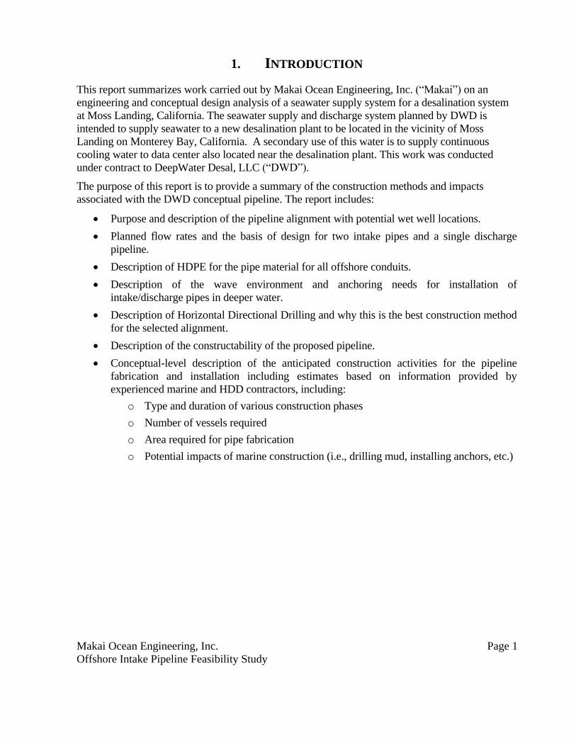
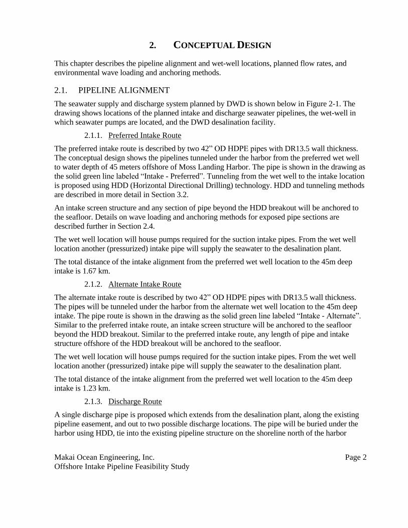
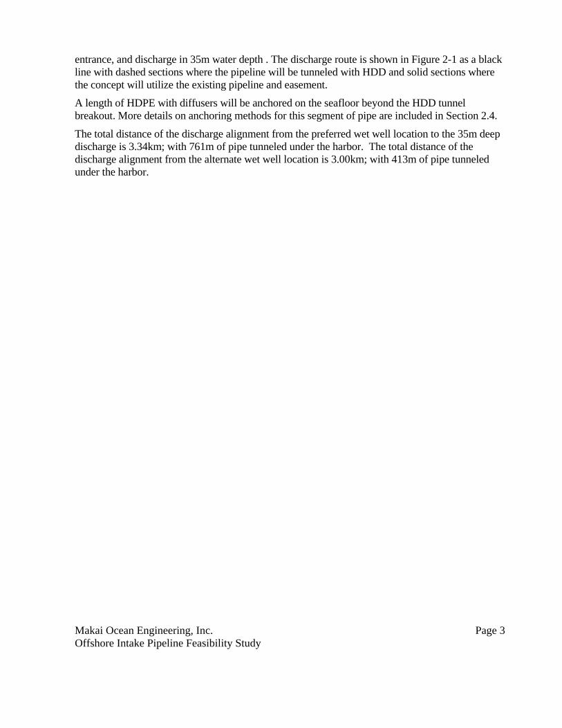
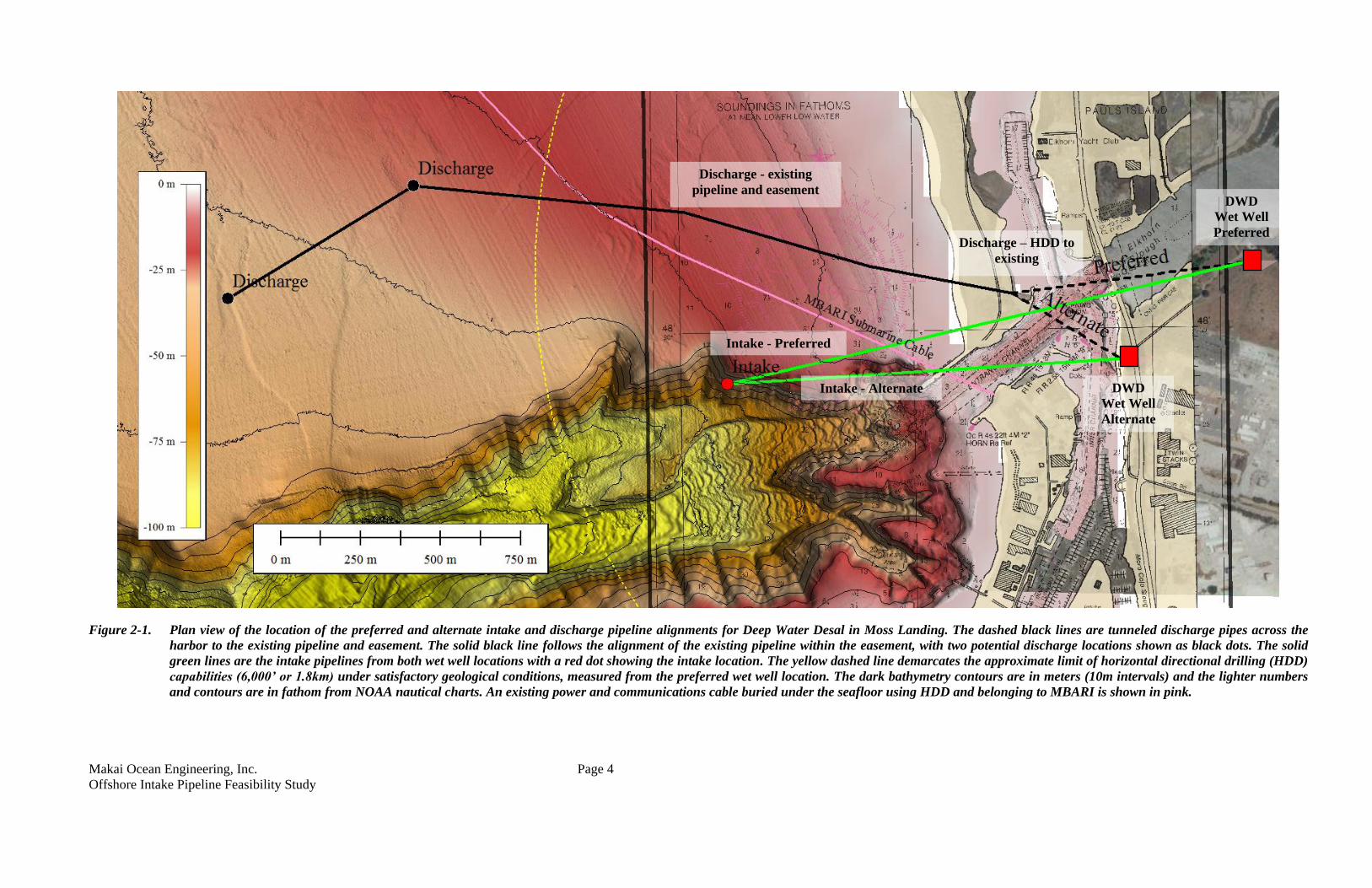
Figure 2-1. Plan view of the location of the preferred and alternate intake and discharge pipeline alignments for Deep Water Desal in Moss Landing. The dashed black lines are tunneled discharge pipes across the
harbor to the existing pipeline and easement. The solid black line follows the alignment of the existing pipeline within the easement, with two potential discharge locations shown as black dots. The solid
green lines are the intake pipelines from both wet well locations with a red dot showing the intake location. The yellow dashed line demarcates the approximate limit of horizontal directional drilling (HDD)
capabilities (6,000’ or 1.8km) under satisfactory geological conditions, measured from the preferred wet well location. The dark bathymetry contours are in meters (10m intervals) and the lighter numbers
and contours are in fathom from NOAA nautical charts. An existing power and communications cable buried under the seafloor using HDD and belonging to MBARI is shown in pink.
DWD
Wet Well
Preferred
DWD
Wet Well
Alternate
Intake - Preferred
Intake - Alternate
Discharge - existing
pipeline and easement
Discharge – HDD to
existing
Makai Ocean Engineering, Inc. Page 5
Offshore Intake Pipeline Feasibility Study
2.2. PIPELINE DESIGN
This Basis of Design (BOD) for the conceptual design of intake and discharge pipelines is as
shown:
Table 1. Intake and Discharge Pipeline Parameters
Parameter Input Data
Intake Flow 34,000 gpm @ 10C
Intake Pipes Dimensions Two intake pipelines at 42‐inch diameter each
Intake Depth ~45m
Discharge Flow 18,200 gpm @ 10C‐11C
Discharge Pipe Dimensions Single 36‐inch diameter line (maintain velocity <6 fps.)
Discharge Depth ~25-35m
Intake Pump Station
Location
Wet-well location Identified in Figure 2-1
2.3. HDPE PIPE MATERIAL
High Density Polyethylene (HDPE) has been selected for the primary pipe material. HDPE has
several advantages over FRP and concrete pipes for this marine pipeline:
Readily Available Commercial Product
High Flexibility/Strain Capability
High Strength/Rugged
Strong Fusion Joints
Corrosion/UV/Biofouling Resistant
Excellent Hydraulic Characteristics
Low Cost
HDPE’s unique characteristics of high flexibility, high strength, high strain capability, strong
fusion joints, no corrosion, and buoyancy provide for fast and low-cost deployment using the
controlled submergence deployment method. HDPE pipe is also a favorite for HDD installation, as
its strength and flexibility make it highly suitable for installation in tunnel borings.
Makai Ocean Engineering, Inc. Page 6
Offshore Intake Pipeline Feasibility Study
2.4. SITE CONDITIONS AND PIPE ANCHORING
Intake structures and lengths of the discharge pipe beyond the HDD breakout locations will need to
be anchored to the seafloor. Most HDPE pipelines installed on the seafloor are ballasted with
concrete gravity anchors. The anchors are typically installed on long segments of the pipe at a
staging site, the segments flanged together, and the entire length of pipe towed into position and
sunk precisely along the alignment in one continuous process called controlled submergence. In
deeper water gravity weights retain the advantage of not requiring diver assistance for installation,
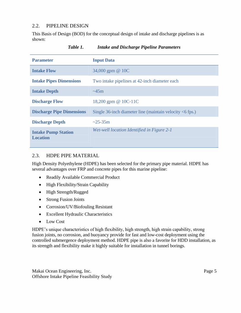
so deep water does not greatly increase installation difficulty. A typical design of the concrete
gravity anchors is shown below in Figure 2-2. The holding power of a gravity anchor is a function
of the friction force between the anchor and the seabed.
Figure 2-2 Gravity Concrete Anchors for an HDPE pipe at Keahole Pt., Hawaii.
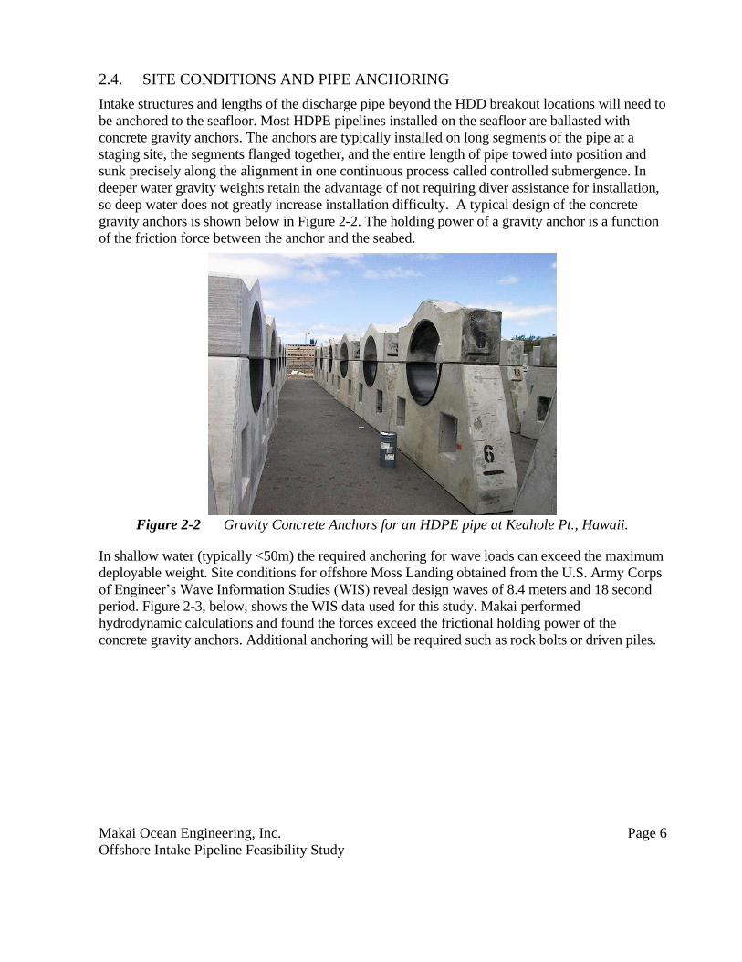
In shallow water (typically <50m) the required anchoring for wave loads can exceed the maximum
deployable weight. Site conditions for offshore Moss Landing obtained from the U.S. Army Corps
of Engineer’s Wave Information Studies (WIS) reveal design waves of 8.4 meters and 18 second
period. Figure 2-3, below, shows the WIS data used for this study. Makai performed
hydrodynamic calculations and found the forces exceed the frictional holding power of the
concrete gravity anchors. Additional anchoring will be required such as rock bolts or driven piles.
Makai Ocean Engineering, Inc. Page 7
Offshore Intake Pipeline Feasibility Study
Figure 2-3. Virtual WIS buoy locations and wave rose data used for offshore climatological
wave conditions.
2.4.1. Additional Anchoring
In diver depths, in which the proposed DWD intake and discharge pipes are installed, the options
and methods for installation of post-deployment anchors include hollow bar or rock-bolt anchors,
manta-ray embedment anchors, or pile anchors. The type of anchor selected will depend on exact
bottom conditions at the anchoring site.
Makai Ocean Engineering, Inc. Page 8
Offshore Intake Pipeline Feasibility Study
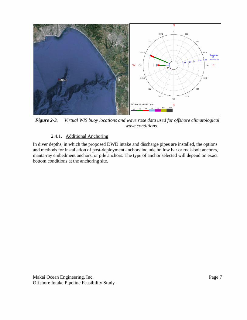
Figure 2-4 Hollow-bar or Rock-bolt anchors attached to concrete gravity anchors.
Both hollow bar and rock bolt anchors are installed by drilling an oversized hole into the seabed,
inserting a threaded steel bar anchor of prescribed length and then filling the annular hole with
grout to form a corrosion resistant and structurally strong connection to the seafloor. An illustration
showing the use of hollow bar anchors is shown in Figure 2-4. These anchors obtain the greatest
holding power in hard bottoms made up or rock or limestone.
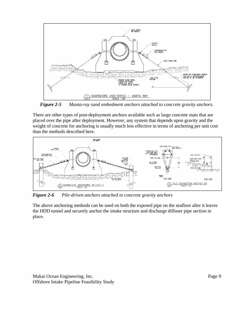
Manta Ray anchors are one type of sand embedment anchor. They are installed by driving the
anchor into the seabed using a jack hammer, removing the driving rod and then pulling up on the
attached anchor rod to rotate and set the anchor deep in the seafloor. Often Manta Rays are
installed by first pre-drilling a hole to reduce the anchor installation loads. A hydraulic loading unit
is used to pull up on and set the anchor. The anchor is set when it has rotated into a horizontal
orientation. Manta Ray anchors are shown in Figure 2-5.
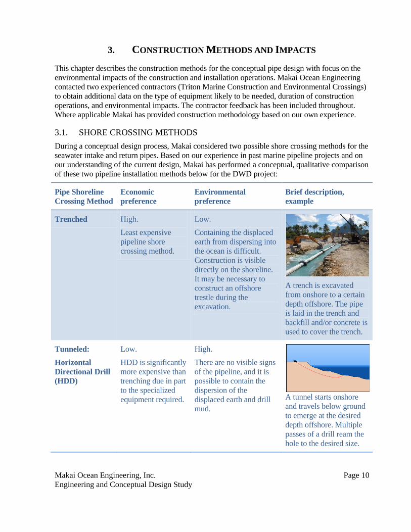
A last anchoring method considered was the use of driven steel pipe piles to hold the pipeline in
place in the shallow zone. One way of attaching piles to the pipe weights to obtain additional
anchoring is shown in Figure 2-6. Driven piles are installed on either side of the weight and
connected with chain and turnbuckles to pipe. The piles are heavy steel pipes of at least 20’ length
that are driven into the seafloor from a moored or jack-up barge. Once mobilized at the site, pile
anchors can be quickly installed if no adverse sub-bottom condition (rock) is encountered. Pile
anchor installation is limited to diver depths as all connections between the piles and the pipe are
made up by divers.
Makai Ocean Engineering, Inc. Page 9
Offshore Intake Pipeline Feasibility Study
Figure 2-5 Manta-ray sand embedment anchors attached to concrete gravity anchors.
There are other types of post-deployment anchors available such as large concrete mats that are
placed over the pipe after deployment. However, any system that depends upon gravity and the
weight of concrete for anchoring is usually much less effective in terms of anchoring per unit cost
than the methods described here.
Figure 2-6 Pile-driven anchors attached to concrete gravity anchors
The above anchoring methods can be used on both the exposed pipe on the seafloor after it leaves
the HDD tunnel and securely anchor the intake structure and discharge diffuser pipe section in
place.
Makai Ocean Engineering, Inc. Page 10
Engineering and Conceptual Design Study
3. CONSTRUCTION METHODS AND IMPACTS
This chapter describes the construction methods for the conceptual pipe design with focus on the
environmental impacts of the construction and installation operations. Makai Ocean Engineering
contacted two experienced contractors (Triton Marine Construction and Environmental Crossings)
to obtain additional data on the type of equipment likely to be needed, duration of construction
operations, and environmental impacts. The contractor feedback has been included throughout.
Where applicable Makai has provided construction methodology based on our own experience.
3.1. SHORE CROSSING METHODS
During a conceptual design process, Makai considered two possible shore crossing methods for the
seawater intake and return pipes. Based on our experience in past marine pipeline projects and on
our understanding of the current design, Makai has performed a conceptual, qualitative comparison
of these two pipeline installation methods below for the DWD project:
Pipe Shoreline
Crossing Method
Economic
preference
Environmental
preference
Brief description,
example
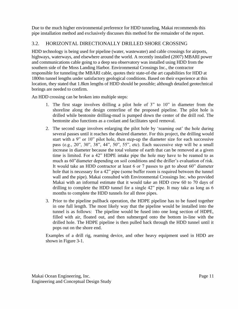
Trenched High.
Least expensive
pipeline shore
crossing method.
Low.
Containing the displaced
earth from dispersing into
the ocean is difficult.
Construction is visible
directly on the shoreline.
It may be necessary to
construct an offshore
trestle during the
excavation.
A trench is excavated
from onshore to a certain
depth offshore. The pipe
is laid in the trench and
backfill and/or concrete is
used to cover the trench.
Tunneled:
Horizontal
Directional Drill
(HDD)
Low.
HDD is significantly
more expensive than
trenching due in part
to the specialized
equipment required.
High.
There are no visible signs
of the pipeline, and it is
possible to contain the
dispersion of the
displaced earth and drill
mud.
A tunnel starts onshore
and travels below ground
to emerge at the desired
depth offshore. Multiple
passes of a drill ream the
hole to the desired size.
Makai Ocean Engineering, Inc. Page 11
Engineering and Conceptual Design Study
Due to the much higher environmental preference for HDD tunneling, Makai recommends this
pipe installation method and exclusively discusses this method for the remainder of the report.
3.2. HORIZONTAL DIRECTIONALLY DRILLED SHORE CROSSING
HDD technology is being used for pipeline (water, wastewater) and cable crossings for airports,
highways, waterways, and elsewhere around the world. A recently installed (2007) MBARI power
and communications cable going to a deep sea observatory was installed using HDD from the
southern side of the Moss Landing Harbor. Environmental Crossings Inc., the contractor
responsible for tunneling the MBARI cable, quotes their state-of-the art capabilities for HDD at
1800m tunnel lengths under satisfactory geological conditions. Based on their experience at this
location, they stated that 1.8km lengths of HDD should be possible; although detailed geotechnical
borings are needed to confirm.
An HDD crossing can be broken into multiple steps:
1. The first stage involves drilling a pilot hole of 3” to 10” in diameter from the
shoreline along the design centerline of the proposed pipeline. The pilot hole is
drilled while bentonite drilling-mud is pumped down the center of the drill rod. The
bentonite also functions as a coolant and facilitates spoil removal.
2. The second stage involves enlarging the pilot hole by ‘reaming out’ the hole during
several passes until it reaches the desired diameter. For this project, the drilling would
start with a 9” or 10” pilot hole, then step-up the diameter size for each successive
pass (e.g., 20”, 30”, 38”, 44”, 50”, 55”, etc). Each successive step will be a small
increase in diameter because the total volume of earth that can be removed at a given
time is limited. For a 42” HDPE intake pipe the hole may have to be reamed to as
much as 60”diameter depending on soil conditions and the driller’s evaluation of risk.
It would take an HDD contractor at least 6 or 7 passes to get to about 60” diameter
hole that is necessary for a 42” pipe (some buffer room is required between the tunnel
wall and the pipe). Makai consulted with Environmental Crossings Inc. who provided
Makai with an informal estimate that it would take an HDD crew 60 to 70 days of
drilling to complete the HDD tunnel for a single 42” pipe. It may take as long as 6
months to complete the HDD tunnels for all three pipes.
3. Prior to the pipeline pullback operation, the HDPE pipeline has to be fused together
in one full length. The most likely way that the pipeline would be installed into the
tunnel is as follows: The pipeline would be fused into one long section of HDPE,
filled with air, floated out, and then submerged onto the bottom in-line with the
drilled hole. The HDPE pipeline is then pulled back through the HDD tunnel until it
pops out on the shore end.
Examples of a drill rig, reaming device, and other heavy equipment used in HDD are
shown in Figure 3-1.

Makai Ocean Engineering, Inc. Page 12
Engineering and Conceptual Design Study
Figure 3-1. HDD drill rig (left) and reaming head (right).
Use of HDD technology will require an onshore area of at least 150’ by 100’ and a source of
freshwater for mixing the drill mud. In addition to the drilling rig, this space is used to house a
drilling fluid cleaning and recirculation unit, drill pipe trailer, water truck, hoses, pumps, driller’s
van, excavator and vacuum pump truck. An aerial view of a site performing HDD, illustrating the
space requirements, is shown in Figure 3-2.
Figure 3-2. Aerial view of HDD in progress.
Ideally, the tunnel would breakout as deep as is possible – as close to the required intake and
discharge depths as possible. The breakout depth for tunneling will be deeper than for a trenched
pipeline as there is only a small additional cost to extend the tunnel to a deeper depth, and the
added depth will provide the advantages of smaller hydrodynamic loads and thus reduced
anchoring requirements.
Makai Ocean Engineering, Inc. Page 13
Engineering and Conceptual Design Study
3.3. HDD ENVIRONMENTAL CONCERNS
Drilling fluid (bentonite) handling and disposal are important considerations in an HDD operation.
1. When the pilot hole is drilled, bentonite will be pumped to the drill head until the drill
head is about 30’ or more away from breaking out on the seabed. Then the contractor
will suck out all the bentonite from the tunnel and fill the hole with fresh water so that
no drill mud escapes into the ocean after the drill breaks out on the seabed.
2. There have been documented cases of the pressurized bentonite leaking out of the
drilled bore through cracks and fissures in the ground while the bore is in progress.
This very fine clay is known to be harmful to some marine organisms. A method that
HDD contractors use to mitigate this risk is to drill the tunnel deeper than the breakout
depth, and then angle the tunnel upwards when they approach the breakout. This
reduces the risk of bentonite escaping through cracks in the seafloor. Some form of
special plug has to be fitted over the end of the bored hole at the offshore end of the
tunnel to avoid bentonite escaping into the ocean.
3. An HDD contractor has suggested to Makai that a reasonable method for containing the
bentonite is to dig a large pit (for example 30’ x 20’ x 6’ deep) on the seafloor just
down the slope from the offshore end of the tunnel mouth. The bentonite is denser than
seawater, and it wants to sink, so when bentonite exits the hole, it will want to flow
down the slope and collect in the excavated pit. Divers will use a suction hose to suck
the bentonite into tanks on the barge for disposal. An alternative to a simple excavated
pit is to construct a steel walled cofferdam in the same location to collect the bentonite.
4. To perform HDD, a land area of roughly 100’ x 150’ is needed during construction.
5. An HDD contractor has suggested that during HDD operations an offshore barge
would be required to provide tension for the HDD tunnel reaming process. This barge
will be moored using a 4 point anchor spread.
3.4. BOTTOM-ANCHORED PIPE
The bottom-mounted segments of pipe located offshore from the breakout location of the tunneled
pipe will be installed using a controlled submergence method. This involves ballasting a section of
air-filled pipeline with concrete anchors clamped around the pipe at set intervals (see Section 2.4).
For longer sections of pipe, the pipe is towed into position, anchored on the shoreward end, and is
slowly flooded with water as it is tensioned in the offshore direction. The proposed alignments for
the DWD concept routes are mostly tunneled pipes with limited exposure to the seafloor. The
limited lengths of pipe that will be installed on the seafloor will use a simpler submergence
process, such that the entire pipe sections would be sunk into place at the same rate with no
anchoring or large offshore pulls required.
As described in Section 2.4, the wave loading for this location exceeds the friction capacity of the
concrete gravity anchors that can be mounted on the pipe. The pipe design will require installation
of post-deployment anchoring as described in Section 2.4.1.
During a controlled submergence deployment, mitered HDPE bends cannot be used; a fabricated
mitered bend cannot take the deployment loads. The offshore bend in the discharge pipe segment
Makai Ocean Engineering, Inc. Page 14
Engineering and Conceptual Design Study
would need to be a gradual bend in the pipe itself, and it would be installed with the help of
restraint bridles. A set of bridles will be designed to hold the pipe in a safe bend radius and
distribute the loads associated with bending over a long section of pipe. Bridles extend back to a
common point which is attached to a preset anchor line offset from the pipe. This preset anchor is
designed to hold the deployment loads without slipping. The anchor and bridles can be removed
after the pipe is in place on the seafloor. The deployment process is likely to require two tug boats,
and two to three tenders. A dive team of at least four commercial divers operating form a devoted
dive vessel will be required to install the post-deployment anchoring. Once staged and towed on-
site, the controlled submergence deployment process could occur within 12 to 24 hours. The length
of time required to install the additional post-deployment anchoring would require several days to
weeks, depending on the dive crew mobilized to complete the work.
A calm water staging area would have to be available to the marine contractor. This is where the
intake pipe and discharge pipe would be fully assembled each into one continuous length. Each
pipe would be fused into one long segment. This site would be used for both the pipes that pulled
into the HDD bored tunnels and for the exposed pipes on the seafloor. For the latter, concrete
gravity anchors would be installed on the air filled floating pipes. Makai has seen harbors, lagoons
and rivers used as quiet water staging sites.
Makai Ocean Engineering, Inc. Page 15
Engineering and Conceptual Design Study
4. CONCLUSIONS
Makai has conducted a preliminary feasibility study of two routes for the seawater intake and
discharge pipelines for planned Deepwater Desalination system development at Moss Landing,
Monterey Bay, California. The investigation included a summary of the general methods for
shoreline crossing and offshore installation of HDPE pipe, collection of detailed environmental site
data, and preliminary assessment of the constructability of the two route concepts. This is a
summary report on our analysis.
Makai's major findings include the following:
It is proposed that all pipes be installed across the shoreline interface to the maximum
depth possible by HDD tunneling to provide a very direct and practical installation method
that minimizes contractor exposure to offshore sea conditions.
The recommendation to use HDD tunneling as an installation method is based on the
following:
o Laying exposed pipe on the seafloor of the harbor is not feasible. The harbor is too
shallow for the height of the HDPE pipe in concrete collar weights.
o Trenching in the surf zone is technically feasible, but will be difficult to accomplish
given the known sea state conditions at the site. Environmental permits for a
trenched shore crossing will be more difficult to obtain than for an HDD tunneled
crossing.
o HDD is likely to be more cost effective than micro-tunneling. HDD does not
require multiple vertical shafts to acts as drive shafts and receiving pits.
For an exposed HDPE pipe on the seafloor, based on the dimension, thickness, rigidity, and
positioning of the pipe with respect to wave currents, the wave loading could exceed the
holding power of the maximum deployable ballast weights. For the pipe dimensions and
type modeled, this is most likely to occur. Smaller diameter pipes of varying material, if
laid on the seafloor, may lessen this risk. However, in virtually all situations and in
particular along this area of the bay, additional post-deployment anchors would be needed
to stabilize the pipe against expected large, long period swell events Wave loading on the
pipe and anchoring requirements are sensitive to the pipe alignment, and the final
anchoring requirements will need to be analyzed in detail once a final path is selected. The
primary effect of additional anchoring is not technical risk but additional installation costs
and long term maintenance costs.