Embed Size (px)
Citation preview
Review
A Comprehensive Study of Key Electric Vehicle (EV) Components, Technologies, Challenges, Impacts, and Future Direction of Development Fuad Un-Noor 1, Sanjeevikumar Padmanaban 2,*, Lucian Mihet-Popa 3, Mohammad Nurunnabi Mollah 1 and Eklas Hossain 4
1 Khulna University of Engineering and Technology, Department of Electrical and Electronic Engineering, Khulna 9203, Bangladesh; [email protected] (F.U); [email protected] (M.N.M)
2 Department of Electrical and Electronics Engineering, University of Johannesburg, Auckland Park, South Africa ; [email protected]
3 Faculty of Engineering, Østfold University College, Kobberslagerstredet 5, 1671 Kråkeroy; Building: S 316, Norway ; [email protected]
4 Oregon Tech, Department of Electrical Engineering & Renewable Energy, OR-97601, USA; [email protected]
* Correspondence: [email protected]; Tel.: +27-79-219-9845
Abstract: Electric vehicles (EV) are getting more commonplace in the transportation sector in recent times. As the present trend suggests, this mode of transport is likely to replace the internal combustion engine (ICE) vehicles in near future. Each of the main EV components has a number of technologies that are currently in use or can become prominent in the future. EVs can cause significant impacts on the environment, power system, and other related sectors. The present power system can face huge instabilities with enough EV penetration; but with proper management and coordination, EVs can be turned into a major contributor to the successful implementation of smart grid. There are possibilities of immense environmental benefits as well, as the EVs can extensively reduce the greenhouse gas emission from the transportation sector. However, there are some major obstacles for EVs to overcome before replacing the ICE vehicles totally. This paper is focused on reviewing all the useful data available on EV configurations, energy sources, motors, charging techniques, optimization techniques, impacts, trends, and possible directions of future developments. Its objective is to provide an overall picture of the current EV technology and ways of future development to assist in future researches in this sector.
Keywords: Electric Vehicle; internal combustion engine; greenhouse gas; optimization techniques; Battery Electric Vehicle (BEV); Hybrid Electric Vehicle (HEV); Plug-in Hybrid Electric Vehicle (PHEV); Fuel Cell Electric Vehicle (FCEV).
1. Introduction
In recent times, electric vehicles (EV) are gaining popularity, and the reasons behind it are many. The most eminent one is its contribution in reducing greenhouse gas (GHG) emission. In 2009, the transportation sector emitted 25% of the GHG produced from energy related sectors [1]. EVs, with enough penetration in the transportation sector, are expected to reduce that. But this is not the only reason that is bringing this century old and once dead concept back to life, and in a commercially viable and available product as well. As a vehicle, an EV is quiet, easy to operate, and does not require fuel costs associated with conventional vehicles. As an urban transport, it is highly useful. It does not use any stored energy or cause any emission while idling, capable of frequent start-stop, provides the total torque from the startup, and does not require any trip to the gas station. It does not cause any smog that is making the city air highly polluted either. The instant torque makes it highly preferable for motorsport. The quietness and low infrared signature makes it useful in military use as well. The power sector is going through a changing phase where renewable
Preprints (www.preprints.org) | NOT PEER-REVIEWED | Posted: 10 May 2017 doi:10.20944/preprints201705.0090.v1
© 2017 by the author(s). Distributed under a Creative Commons CC BY license.
Peer-reviewed version available at Energies 2017, 10, 1217; doi:10.3390/en10081217

2 of 71
sources are gaining momentum. The next generation power grid, called ‘smart grid’ is also being developed. EVs are being considered a major contributor to this new power system comprised of renewable generating facilities and advanced grid system. All these have led to a renewed interest and development in this mode of transport.
The idea to employ electric motors to drive a vehicle surfaced after the innovation of the motor itself. From 1897 to 1900, the EVs became 28% of the total vehicles and were preferred over the internal combustion engine (ICE) ones [1]. But the ICE types gained momentum afterwards, and with oil prices very low, they soon conquered the market, became much more mature and advanced, and EVs got lost into oblivion. A chance of resurrection appeared in the form of the EV1 from general motors, which was launched in 1996, and quickly became very popular. Other leading carmakers, including Ford, Toyota, and Honda brought out their own EVs as well. Toyota’s highly successful Prius, the first commercial hybrid electric vehicle (HEV), was launched in Japan in 1997, with 18,000 units sold in the first year of production [1]. Today, almost none of those twentieth century EVs exist; an exception can be Toyota Prius, still going strong in a better and evolved form. Now the market is dominated by Nissan Leaf, Chevrolet Volt, and Tesla Model S; whereas the Chinese market is in the grip of BYD Auto Co., Ltd.
EVs can be considered as a combination of different subsystems. Each of these systems interact with each other to make the EV work, and there are multiple technologies that can be employed to operate the subsystems. In fig. 1, key parts of these subsystems and their contribution to the total system is demonstrated. Some of these parts have to work extensively with some of the others, whereas some have to interact very less. Whatever the case may be, it is the combined work of all these systems that make an EV operate.
Figure 1: Major EV subsystems and their interactions [2].
There are quite a few configurations and options to build an EV with. EVs can be solely driven with stored electrical power, some can generate this energy from an ICE, and there are also some vehicles that employ both the ICE and the electrical motors together. The general classification is discussed in section II whereas different configurations are described in section III. EVs use different types of energy storages to keep their power stored. Though batteries are the most used ones, ultracapacitors, flywheels and fuel cells are also coming up as potential energy storage systems (ESS). Section IV is dedicated to these energy sources. The types of motors that have been used in EVs and can be used in future are discussed in section V. Different charging voltages and charger configurations can be used in charging the vehicles. Wireless charging is also being examined and experimented with to increase convenience. These charger standards, configurations and power
Preprints (www.preprints.org) | NOT PEER-REVIEWED | Posted: 10 May 2017 doi:10.20944/preprints201705.0090.v1
Peer-reviewed version available at Energies 2017, 10, 1217; doi:10.3390/en10081217
3 of 71
conversion systems are demonstrated in sections VI and VII. Section VIII discusses the effects EVs create in different sectors. Being a developing technology, EVs still have many limitations that have to be overcome to enable them to penetrate deeper into the market. These limitations are pointed out in section IX along with probable solutions. Section X summed up some strategies used in EVs to enable proper use of the available power, followed by section XII containing the trends and sectors that may get developed in the future. The topics covered in this paper have been discussed different literatures. Over the years, a number of publications have been made discussing different aspects of EV technology. This paper is created as an effort to sum up all these works to demonstrate the state-of-the art of the system and to position different technologies side by side to find out their merits and demerits, and in some cases, which one of them can make its way to the future EVs.
2. EV types
EVs can run solely on electric propulsion or they can have an ICE working alongside it. Having only batteries as energy source makes the basic kind of EVs, but there are kinds that can employ other modes of energy source. These can be called as hybrid EVs (HEV). The International Electrotechnical Commission’s Technical Committee 69 (Electric Road Vehicles) proposed that vehicles using two or more types of energy source, storage or converters can be called as an HEV as long as at least one of those provide electrical energy [2]. This definition makes a lot of combination possible for HEVs like ICE and battery, battery and flywheel, battery and capacitor, battery and fuel cell etc. Therefore, common population and specialists both started calling vehicles with an ICE and electric motor combination HEVs, battery and capacitor ones ultra-capacitor assisted EV and the ones with battery and fuel cell as FCEVs [2]. These terminologies has become widely accepted and according to this norm, EVs can be categorized as following: 1. Battery Electric Vehicle (BEV) 2. Hybrid Electric Vehicle (HEV) 3. Plug-in Hybrid Electric Vehicle (PHEV) 4. Fuel Cell Electric Vehicle (FCEV)
2.1. Battery Electric Vehicle (BEV)
EVs with only batteries to provide power to the drivetrain are known as BEVs. BEVs have to rely solely on the energy stored in their battery packs, therefore the range of such vehicles depends directly on the battery capacity. Typically they can cover 100-250 km on one charge [3], whereas the top-tier models can go a lot further, from 300 to 500 km [3]. These ranges depend on driving condition and style, vehicle configurations, road conditions, climate, battery type and age. Once depleted, charging the battery pack takes quite a lot of time compared to refueling a conventional ICE vehicle. It can take as long as 36 hours completely replenish the batteries [4][ 5], there are far less time consuming ones as well, but none is comparable to the little time required to refill a fuel tank. Charging time depends on the charger configuration, its infrastructure and operating power level. Advantages of BEVs are their simple construction, operation and convenience. These do not produce any greenhouse gas (GHG), do not create any noise and therefore beneficial to the environment. Electric propulsion provides instant and high torques, even at low speeds. These advantages, coupled with their limitation of range, makes them the perfect vehicle to use in urban areas. Nissan Leaf and Teslas are some high-selling BEVs these days, along with some Chinese vehicles.
Figure 2: BEV configuration [3].
Preprints (www.preprints.org) | NOT PEER-REVIEWED | Posted: 10 May 2017 doi:10.20944/preprints201705.0090.v1
Peer-reviewed version available at Energies 2017, 10, 1217; doi:10.3390/en10081217
4 of 71
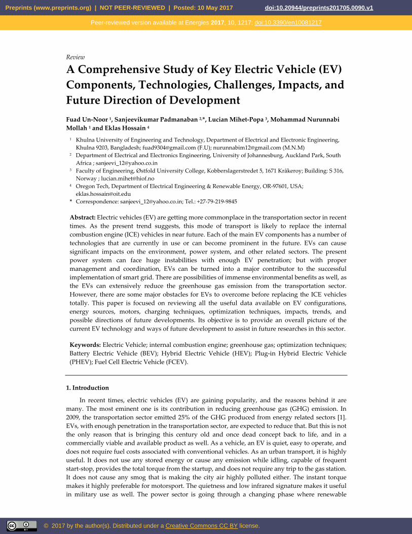
Figure 3: Federal Urban Driving Schedule torque-speed requirements [2].
2.2. Hybrid Electric Vehicle (HEV)
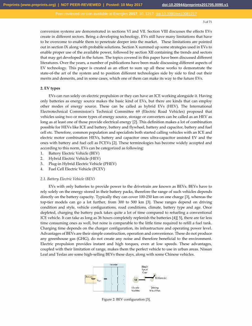
HEVs employ both an ICE and an electrical powertrain to power the vehicle. The combination of these two can come in different forms which are discussed later. An HEV uses the electric propulsion system when the power demand is low. It is a great advantage in low speed conditions like urban areas, it also reduces the fuel consumption as the engine stays totally off during idling periods, for example, traffic jams. This feature also reduces the GHG emission. When higher speed is needed, the HEV switches to the ICE. The two drivetrains can also work together to improve the performance. Hybrid power systems are used extensively to reduce or to completely remove turbo lag in turbocharged cars, like the Acura NSX. It enhances performance also by filling the gaps between gear shifts and providing speed boosts when required. The ICE can charge up the batteries, HEVs can also retrieve energy by means of regenerative braking.
Therefore, HEVs are primarily ICE driven cars that use an electrical drivetrain to improve mileage or for performance enhancement. To attain these features. HEV configurations are being widely adopted by car manufacturers.
Figure 4: HEV basic operating principle [6].
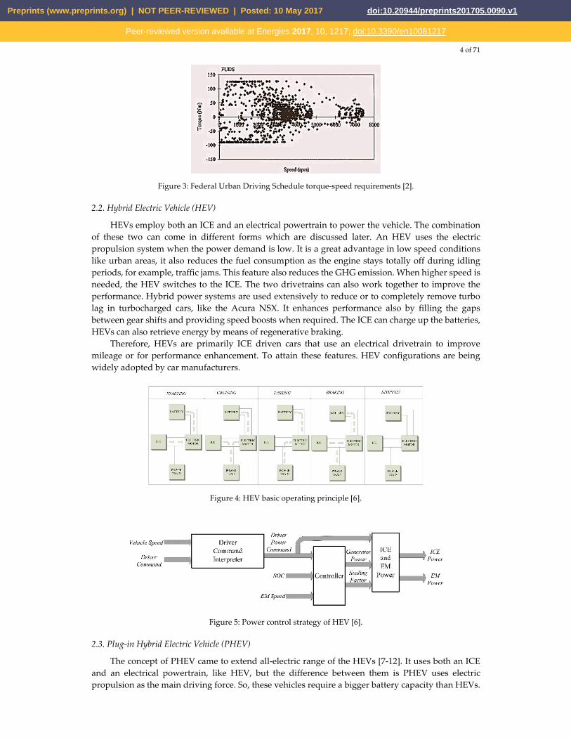
Figure 5: Power control strategy of HEV [6].
2.3. Plug-in Hybrid Electric Vehicle (PHEV)
The concept of PHEV came to extend all-electric range of the HEVs [7-12]. It uses both an ICE and an electrical powertrain, like HEV, but the difference between them is PHEV uses electric propulsion as the main driving force. So, these vehicles require a bigger battery capacity than HEVs.
Preprints (www.preprints.org) | NOT PEER-REVIEWED | Posted: 10 May 2017 doi:10.20944/preprints201705.0090.v1
Peer-reviewed version available at Energies 2017, 10, 1217; doi:10.3390/en10081217
5 of 71
PHEVs start in ‘all electric’ mode, runs on electricity and when the batteries are low in charge, it calls in the ICE to provide a boost or to charge up the battery pack. The ICE is used here to extend the range. PHEVs can charge their batteries directly from the grid (which HEVs cannot), they also have the facility to utilize regenerative braking. PHEVs’ ability to run solely on electricity for most of the time makes its carbon footprint smaller than the HEVs. They consume less fuel as well and thus reduces the associated cost. The vehicle market is now quite populated with these, Chevrolet Volt and Toyota Prius sales show their popularity as well.
2.4. Fuel cell electric vehicle (FCEV)
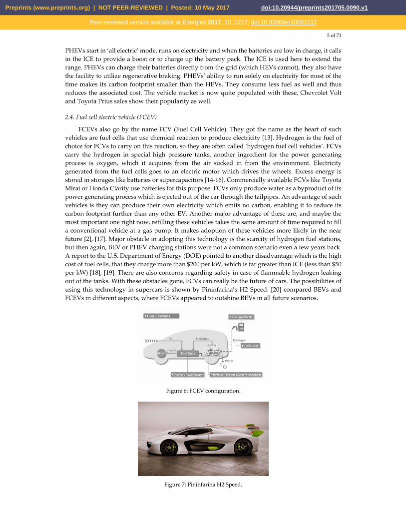
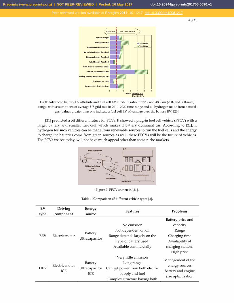
FCEVs also go by the name FCV (Fuel Cell Vehicle). They got the name as the heart of such vehicles are fuel cells that use chemical reaction to produce electricity [13]. Hydrogen is the fuel of choice for FCVs to carry on this reaction, so they are often called ‘hydrogen fuel cell vehicles’. FCVs carry the hydrogen in special high pressure tanks, another ingredient for the power generating process is oxygen, which it acquires from the air sucked in from the environment. Electricity generated from the fuel cells goes to an electric motor which drives the wheels. Excess energy is stored in storages like batteries or supercapacitors [14-16]. Commercially available FCVs like Toyota Mirai or Honda Clarity use batteries for this purpose. FCVs only produce water as a byproduct of its power generating process which is ejected out of the car through the tailpipes. An advantage of such vehicles is they can produce their own electricity which emits no carbon, enabling it to reduce its carbon footprint further than any other EV. Another major advantage of these are, and maybe the most important one right now, refilling these vehicles takes the same amount of time required to fill a conventional vehicle at a gas pump. It makes adoption of these vehicles more likely in the near future [2], [17]. Major obstacle in adopting this technology is the scarcity of hydrogen fuel stations, but then again, BEV or PHEV charging stations were not a common scenario even a few years back. A report to the U.S. Department of Energy (DOE) pointed to another disadvantage which is the high cost of fuel cells, that they charge more than $200 per kW, which is far greater than ICE (less than $50 per kW) [18], [19]. There are also concerns regarding safety in case of flammable hydrogen leaking out of the tanks. With these obstacles gone, FCVs can really be the future of cars. The possibilities of using this technology in supercars is shown by Pininfarina’s H2 Speed. [20] compared BEVs and FCEVs in different aspects, where FCEVs appeared to outshine BEVs in all future scenarios.
Figure 6: FCEV configuration.
Figure 7: Pininfarina H2 Speed.
Preprints (www.preprints.org) | NOT PEER-REVIEWED | Posted: 10 May 2017 doi:10.20944/preprints201705.0090.v1
Peer-reviewed version available at Energies 2017, 10, 1217; doi:10.3390/en10081217
6 of 71
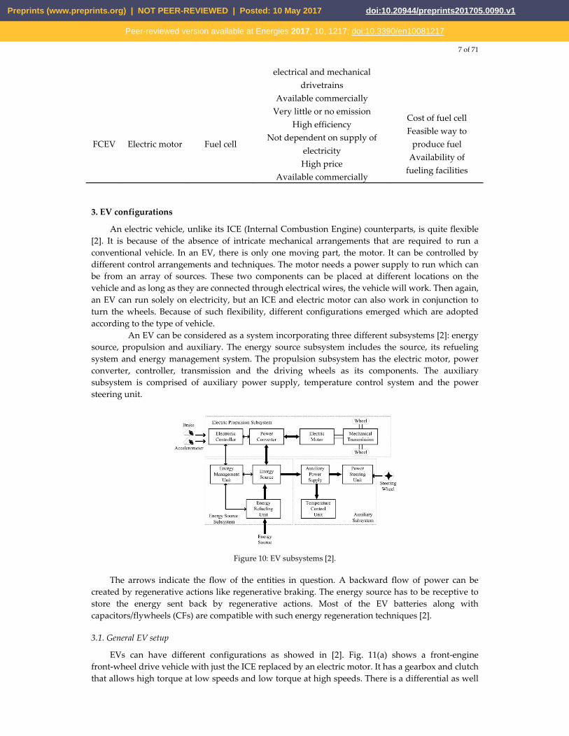
Fig 8: Advanced battery EV attribute and fuel cell EV attribute ratio for 320- and 480-km (200- and 300-mile)
range, with assumptions of average US grid mix in 2010–2020 time-range and all hydrogen made from natural gas (values greater than one indicate a fuel cell EV advantage over the battery EV) [20].
[21] predicted a bit different future for FCVs. It showed a plug-in fuel cell vehicle (PFCV) with a larger battery and smaller fuel cell, which makes it battery dominant car. According to [21], if hydrogen for such vehicles can be made from renewable sources to run the fuel cells and the energy to charge the batteries come from green sources as well, these PFCVs will be the future of vehicles. The FCVs we see today, will not have much appeal other than some niche markets.
Figure 9: PFCV shown in [21].
Table 1: Comparison of different vehicle types [2].
EV type
Driving component
Energy source
Features Problems
BEV Electric motor Battery
Ultracapacitor
No emission Not dependent on oil
Range depends largely on the type of battery used
Available commercially
Battery price and capacity Range
Charging time Availability of
charging stations High price
HEV Electric motor
ICE
Battery Ultracapacitor
ICE
Very little emission Long range
Can get power from both electric supply and fuel
Complex structure having both
Management of the energy sources
Battery and engine size optimization
Preprints (www.preprints.org) | NOT PEER-REVIEWED | Posted: 10 May 2017 doi:10.20944/preprints201705.0090.v1
Peer-reviewed version available at Energies 2017, 10, 1217; doi:10.3390/en10081217
7 of 71
electrical and mechanical drivetrains
Available commercially
FCEV Electric motor Fuel cell
Very little or no emission High efficiency
Not dependent on supply of electricity High price
Available commercially
Cost of fuel cell Feasible way to
produce fuel Availability of
fueling facilities
3. EV configurations
An electric vehicle, unlike its ICE (Internal Combustion Engine) counterparts, is quite flexible [2]. It is because of the absence of intricate mechanical arrangements that are required to run a conventional vehicle. In an EV, there is only one moving part, the motor. It can be controlled by different control arrangements and techniques. The motor needs a power supply to run which can be from an array of sources. These two components can be placed at different locations on the vehicle and as long as they are connected through electrical wires, the vehicle will work. Then again, an EV can run solely on electricity, but an ICE and electric motor can also work in conjunction to turn the wheels. Because of such flexibility, different configurations emerged which are adopted according to the type of vehicle.
An EV can be considered as a system incorporating three different subsystems [2]: energy source, propulsion and auxiliary. The energy source subsystem includes the source, its refueling system and energy management system. The propulsion subsystem has the electric motor, power converter, controller, transmission and the driving wheels as its components. The auxiliary subsystem is comprised of auxiliary power supply, temperature control system and the power steering unit.
Figure 10: EV subsystems [2].
The arrows indicate the flow of the entities in question. A backward flow of power can be created by regenerative actions like regenerative braking. The energy source has to be receptive to store the energy sent back by regenerative actions. Most of the EV batteries along with capacitors/flywheels (CFs) are compatible with such energy regeneration techniques [2].
3.1. General EV setup
EVs can have different configurations as showed in [2]. Fig. 11(a) shows a front-engine front-wheel drive vehicle with just the ICE replaced by an electric motor. It has a gearbox and clutch that allows high torque at low speeds and low torque at high speeds. There is a differential as well
Preprints (www.preprints.org) | NOT PEER-REVIEWED | Posted: 10 May 2017 doi:10.20944/preprints201705.0090.v1
Peer-reviewed version available at Energies 2017, 10, 1217; doi:10.3390/en10081217
8 of 71
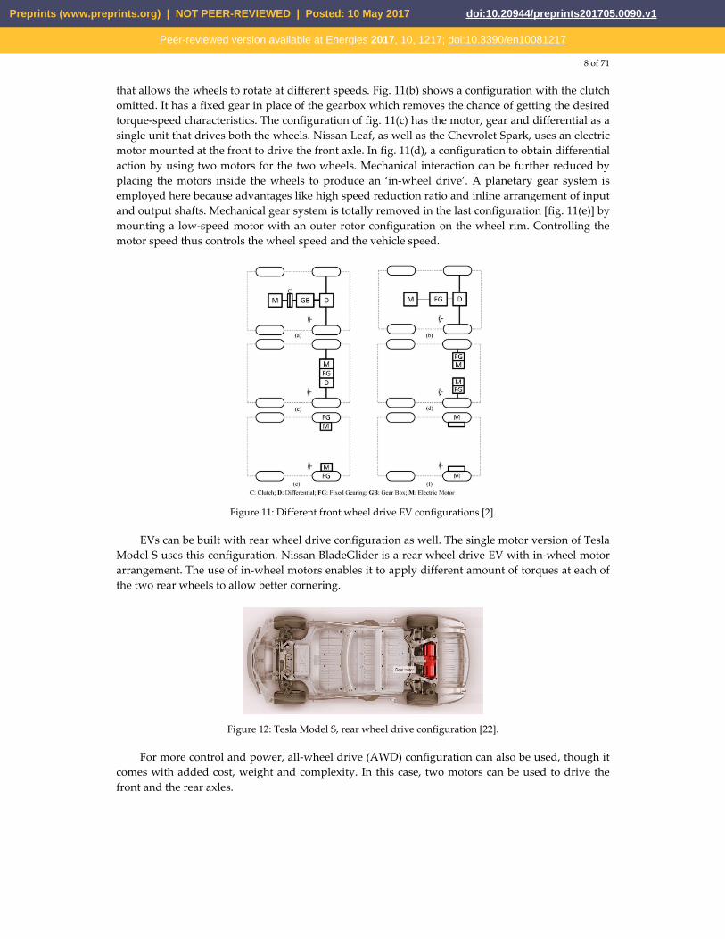
that allows the wheels to rotate at different speeds. Fig. 11(b) shows a configuration with the clutch omitted. It has a fixed gear in place of the gearbox which removes the chance of getting the desired torque-speed characteristics. The configuration of fig. 11(c) has the motor, gear and differential as a single unit that drives both the wheels. Nissan Leaf, as well as the Chevrolet Spark, uses an electric motor mounted at the front to drive the front axle. In fig. 11(d), a configuration to obtain differential action by using two motors for the two wheels. Mechanical interaction can be further reduced by placing the motors inside the wheels to produce an ‘in-wheel drive’. A planetary gear system is employed here because advantages like high speed reduction ratio and inline arrangement of input and output shafts. Mechanical gear system is totally removed in the last configuration [fig. 11(e)] by mounting a low-speed motor with an outer rotor configuration on the wheel rim. Controlling the motor speed thus controls the wheel speed and the vehicle speed.
Figure 11: Different front wheel drive EV configurations [2].
EVs can be built with rear wheel drive configuration as well. The single motor version of Tesla Model S uses this configuration. Nissan BladeGlider is a rear wheel drive EV with in-wheel motor arrangement. The use of in-wheel motors enables it to apply different amount of torques at each of the two rear wheels to allow better cornering.
Figure 12: Tesla Model S, rear wheel drive configuration [22].
For more control and power, all-wheel drive (AWD) configuration can also be used, though it comes with added cost, weight and complexity. In this case, two motors can be used to drive the front and the rear axles.
Preprints (www.preprints.org) | NOT PEER-REVIEWED | Posted: 10 May 2017 doi:10.20944/preprints201705.0090.v1
Peer-reviewed version available at Energies 2017, 10, 1217; doi:10.3390/en10081217
9 of 71
Figure 13: Tesla Model S, all-wheel drive configuration [22].
AWD configurations are useful to provide better traction in slippery conditions, they can also use torque vectoring for better cornering performance and handling.
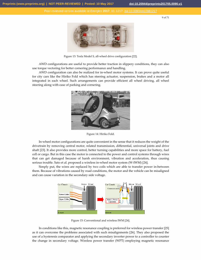
AWD configuration can also be realized for in-wheel motor systems. It can prove quite useful for city cars like the Hiriko Fold which has steering actuator, suspension, brakes and a motor all integrated in each wheel. Such arrangements can provide efficient all wheel driving, all wheel steering along with ease of parking and cornering.
Figure 14: Hiriko Fold.
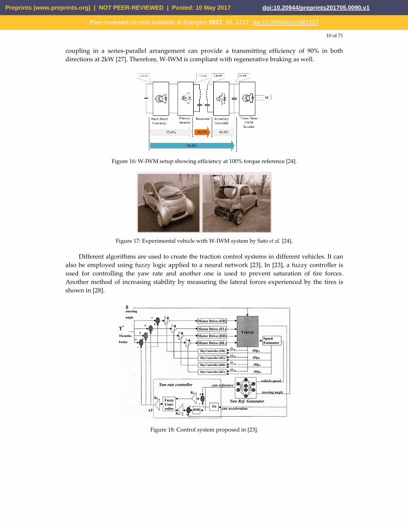
In-wheel motor configurations are quite convenient in the sense that it reduces the weight of the drivetrain by removing central motor, related transmission, differential, universal joints and drive shaft [23]. It also provides more control, better turning capabilities and more space for battery, fuel cell or cargo. But in this case the motor is connected to the power and control systems through wires that can get damaged because of harsh environment, vibration and acceleration, thus causing serious trouble. Sato et al. proposed a wireless in-wheel motor system (W-IWM) [24].
Simply put, the wires are replaced by two coils which are able to transfer power in-between them. Because of vibrations caused by road conditions, the motor and the vehicle can be misaligned and can cause variation in the secondary side voltage.
Figure 15: Conventional and wireless IWM [24].
In conditions like this, magnetic resonance coupling is preferred for wireless power transfer [25] as it can overcome the problems associated with such misalignments [26]. They also proposed the use of a hysteresis comparator and applying the secondary inverter power to a controller to counter the change in secondary voltage. Wireless power transfer (WPT) employing magnetic resonance
Preprints (www.preprints.org) | NOT PEER-REVIEWED | Posted: 10 May 2017 doi:10.20944/preprints201705.0090.v1
Peer-reviewed version available at Energies 2017, 10, 1217; doi:10.3390/en10081217
10 of 71
coupling in a series-parallel arrangement can provide a transmitting efficiency of 90% in both directions at 2kW [27]. Therefore, W-IWM is compliant with regenerative braking as well.
Figure 16: W-IWM setup showing efficiency at 100% torque reference [24].
Figure 17: Experimental vehicle with W-IWM system by Sato et al. [24].
Different algorithms are used to create the traction control systems in different vehicles. It can also be employed using fuzzy logic applied to a neural network [23]. In [23], a fuzzy controller is used for controlling the yaw rate and another one is used to prevent saturation of tire forces. Another method of increasing stability by measuring the lateral forces experienced by the tires is shown in [28].
Figure 18: Control system proposed in [23].
Preprints (www.preprints.org) | NOT PEER-REVIEWED | Posted: 10 May 2017 doi:10.20944/preprints201705.0090.v1
Peer-reviewed version available at Energies 2017, 10, 1217; doi:10.3390/en10081217

11 of 71
Figure 19: Different forces acting on a vehicle [23].
FCEVs have the same driving principle as the BEVs, they does not require an ICE, therefore these configurations apply for FCEVs as well.
3.2. HEV setup
HEVs use both an electrical propulsion system and an ICE. Various ways in which these two can be set up to spin the wheels creates different configurations that can be summed up in four categories [1]: 1. Series hybrid 2. Parallel hybrid 3. Series-parallel hybrid 4. Complex hybrid
3.2.1. Series hybrid
This configuration is the simplest one to make an HEV. Only the motor is connected to the wheels here, the engine is used to run a generator which provides the electrical power. It can be put as an EV that is assisted by an ICE generator [2].
Figure 20: Drivetrain of series hybrid system [29].
Table 2: Properties of series configuration [30].
Advantages
Efficient and optimized power-plant Possibilities for modular power-plant
Optimized drive line Possibility of swift ‘black box’ service exchange
Preprints (www.preprints.org) | NOT PEER-REVIEWED | Posted: 10 May 2017 doi:10.20944/preprints201705.0090.v1
Peer-reviewed version available at Energies 2017, 10, 1217; doi:10.3390/en10081217
12 of 71
Long lifetime Mature technology
Fast response Capable of attaining zero emission
Limitations Large traction drive system
Requirement of proper algorithms Multiple energy conversion steps
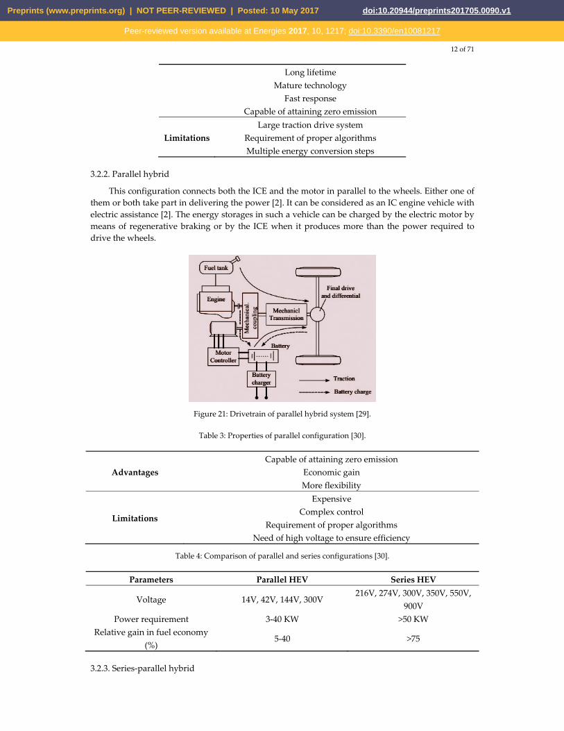
3.2.2. Parallel hybrid
This configuration connects both the ICE and the motor in parallel to the wheels. Either one of them or both take part in delivering the power [2]. It can be considered as an IC engine vehicle with electric assistance [2]. The energy storages in such a vehicle can be charged by the electric motor by means of regenerative braking or by the ICE when it produces more than the power required to drive the wheels.
Figure 21: Drivetrain of parallel hybrid system [29].
Table 3: Properties of parallel configuration [30].
Advantages Capable of attaining zero emission
Economic gain More flexibility
Limitations
Expensive Complex control
Requirement of proper algorithms Need of high voltage to ensure efficiency
Table 4: Comparison of parallel and series configurations [30].
Parameters Parallel HEV Series HEV
Voltage 14V, 42V, 144V, 300V 216V, 274V, 300V, 350V, 550V,
900V Power requirement 3-40 KW >50 KW
Relative gain in fuel economy (%)
5-40 >75
3.2.3. Series-parallel hybrid
Preprints (www.preprints.org) | NOT PEER-REVIEWED | Posted: 10 May 2017 doi:10.20944/preprints201705.0090.v1
Peer-reviewed version available at Energies 2017, 10, 1217; doi:10.3390/en10081217
13 of 71
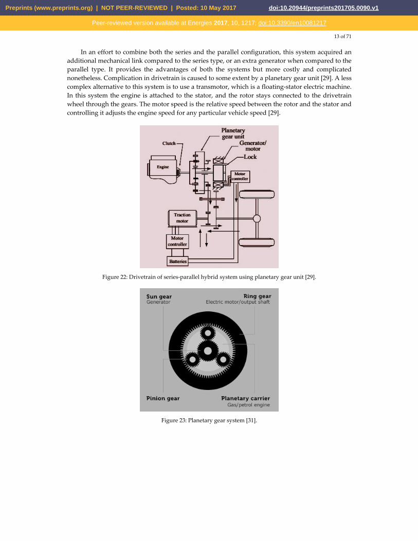
In an effort to combine both the series and the parallel configuration, this system acquired an additional mechanical link compared to the series type, or an extra generator when compared to the parallel type. It provides the advantages of both the systems but more costly and complicated nonetheless. Complication in drivetrain is caused to some extent by a planetary gear unit [29]. A less complex alternative to this system is to use a transmotor, which is a floating-stator electric machine. In this system the engine is attached to the stator, and the rotor stays connected to the drivetrain wheel through the gears. The motor speed is the relative speed between the rotor and the stator and controlling it adjusts the engine speed for any particular vehicle speed [29].
Figure 22: Drivetrain of series-parallel hybrid system using planetary gear unit [29].
Figure 23: Planetary gear system [31].
Preprints (www.preprints.org) | NOT PEER-REVIEWED | Posted: 10 May 2017 doi:10.20944/preprints201705.0090.v1
Peer-reviewed version available at Energies 2017, 10, 1217; doi:10.3390/en10081217

14 of 71
Figure 24: Drivetrain of series-parallel hybrid system using transmotor [29].
3.2.4. Complex hybrid
This system has one major difference with the series-parallel system, that is, it allows bidirectional flow of power whereas the series-parallel can provide only unidirectional power flow. But by current market terminologies, this configuration too is denoted as series-parallel system. High complexity and cost is a drawback of this system too but it is adopted by some vehicles to use dual-axle propulsion [2].
Constantly variable transmission (CVT) can be used for power splitting in a complex hybrid system or choosing between the power sources to drive the wheels. Electric arrangements can be used for such processes and is dubbed as e-CVT. It is developed and introduced by Toyota Motor Co. CVTs can be implemented hydraulically, mechanically, hydro-mechanically or electromechanically [32]. Two methods of power splitting - input splitting and complex splitting are shown in [32]. Input splitting got the name as it has a power split device placed at the transmission input. This system is used by certain Toyota and Ford models [32]. [32] also showed different modes of these two splitting mechanisms and provided descriptions of e-CVT systems adopted by different manufacturers.
Figure 25: Input split e-CVT system [32].
Preprints (www.preprints.org) | NOT PEER-REVIEWED | Posted: 10 May 2017 doi:10.20944/preprints201705.0090.v1
Peer-reviewed version available at Energies 2017, 10, 1217; doi:10.3390/en10081217
15 of 71
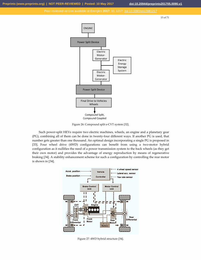
Figure 26: Compound split e-CVT system [32].
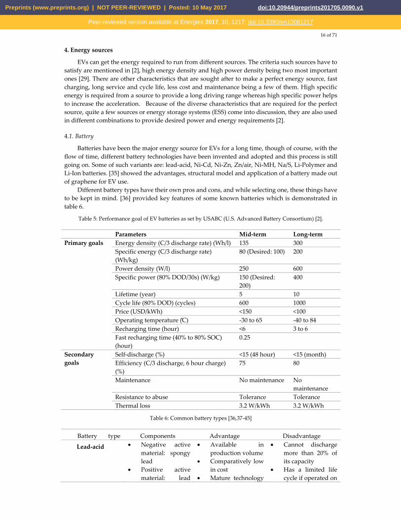
Such power-split HEVs require two electric machines, wheels, an engine and a planetary gear (PG), combining all of them can be done in twenty-four different ways. If another PG is used, that number gets greater than one thousand. An optimal design incorporating a single PG is proposed in [33]. Four wheel drive (4WD) configurations can benefit from using a two-motor hybrid configuration as it nullifies the need of a power transmission system to the back wheels (as they get their own motor) and provides the advantage of energy reproduction by means of regenerative braking [34]. A stability enhancement scheme for such a configuration by controlling the rear motor is shown in [34].
Figure 27: 4WD hybrid structure [34].
Preprints (www.preprints.org) | NOT PEER-REVIEWED | Posted: 10 May 2017 doi:10.20944/preprints201705.0090.v1
Peer-reviewed version available at Energies 2017, 10, 1217; doi:10.3390/en10081217
16 of 71
4. Energy sources
EVs can get the energy required to run from different sources. The criteria such sources have to satisfy are mentioned in [2], high energy density and high power density being two most important ones [29]. There are other characteristics that are sought after to make a perfect energy source, fast charging, long service and cycle life, less cost and maintenance being a few of them. High specific energy is required from a source to provide a long driving range whereas high specific power helps to increase the acceleration. Because of the diverse characteristics that are required for the perfect source, quite a few sources or energy storage systems (ESS) come into discussion, they are also used in different combinations to provide desired power and energy requirements [2].
4.1. Battery
Batteries have been the major energy source for EVs for a long time, though of course, with the flow of time, different battery technologies have been invented and adopted and this process is still going on. Some of such variants are: lead-acid, Ni-Cd, Ni-Zn, Zn/air, Ni-MH, Na/S, Li-Polymer and Li-Ion batteries. [35] showed the advantages, structural model and application of a battery made out of graphene for EV use.
Different battery types have their own pros and cons, and while selecting one, these things have to be kept in mind. [36] provided key features of some known batteries which is demonstrated in table 6.
Table 5: Performance goal of EV batteries as set by USABC (U.S. Advanced Battery Consortium) [2].
Parameters Mid-term Long-termPrimary goals Energy density (C/3 discharge rate) (Wh/l) 135 300
Specific energy (C/3 discharge rate) (Wh/kg)
80 (Desired: 100) 200
Power density (W/l) 250 600 Specific power (80% DOD/30s) (W/kg) 150 (Desired:
200) 400
Lifetime (year) 5 10 Cycle life (80% DOD) (cycles) 600 1000 Price (USD/kWh) <150 <100 Operating temperature ( C) -30 to 65 -40 to 84 Recharging time (hour) <6 3 to 6 Fast recharging time (40% to 80% SOC) (hour)
0.25
Secondary goals
Self-discharge (%) <15 (48 hour) <15 (month) Efficiency (C/3 discharge, 6 hour charge) (%)
75 80
Maintenance No maintenance No maintenance
Resistance to abuse Tolerance Tolerance Thermal loss 3.2 W/kWh 3.2 W/kWh
Table 6: Common battery types [36,37-45]
Battery type Components Advantage Disadvantage
Lead-acid • Negative active material: spongy lead
• Positive active material: lead
• Available in production volume
• Comparatively low in cost
• Mature technology
• Cannot discharge more than 20% of its capacity
• Has a limited life cycle if operated on
Preprints (www.preprints.org) | NOT PEER-REVIEWED | Posted: 10 May 2017 doi:10.20944/preprints201705.0090.v1
Peer-reviewed version available at Energies 2017, 10, 1217; doi:10.3390/en10081217

17 of 71
oxide • Electrolyte:
diluted sulfuric acid
as used for over fifty years
a deep rate of SOC (state of charge)
• Low energy and power density
• Heavier • May need
maintenance
NiMH
(Nickel–Metal
Hydride)
• Electrolyte: alkaline solution
• Positive electrode: nickel hydroxide
• Negative electrode: alloy of nickel, titanium, vanadium and other metals.
• Double energy density compared to lead-acid
• Harmless to the environment
• Recyclable • Safe operation at
high voltage • Can store
volumetric power and energy
• Cycle life is longer • Operating
temperature range is long
• Resistant to over-charge and discharge
• Reduced lifetime of around 200-300 cycles if discharged rapidly on high load currents
• Reduced usable power because of memory effect
Li-Ion
(Lithium-Ion)
• Positive electrode: oxidized cobalt material
• Negative electrode: carbon material
• Electrolyte: lithium salt solution in an organic solvent
• High energy density, twice of NiMH
• Good performance at high temperature
• Recyclable • Low memory effect• High specific
power • High specific
energy • Long battery life,
around 1000 cycles
• High cost • Recharging still
takes quite a long time, though better than most batteries
Ni-Zn
(Nickel-Zinc)
• Positive electrode: nickel oxyhydroxide
• Negative electrode: zinc
• High energy density
• High power density
• Uses low cost material
• Capable of deep cycle
• Friendly to environment
• Usable in a wide temperature range from -10°C to 50°C
• Fast growth of dendrite, preventing use in vehicles
Preprints (www.preprints.org) | NOT PEER-REVIEWED | Posted: 10 May 2017 doi:10.20944/preprints201705.0090.v1
Peer-reviewed version available at Energies 2017, 10, 1217; doi:10.3390/en10081217

18 of 71
Ni-Cd
(Nickel-Cadmium)
• Positive electrode: nickel hydroxide
• Negative electrode: cadmium
• Long lifetime • Can discharge fully
without being damaged
• Recyclable
• Cadmium can cause pollution in case of not being properly disposed of
• Costly for vehicular application
Table 7: Comparison of different battery types [46]
Advantages
over
Lead-acid Ni-Cd
(Nickel-Cadmiu
m)
NiMH
(Nickel–Meta
l Hydride)
Li-Ion (Lithium-Ion)
Convention
al
Polymer
Lead-acid • Volumetric energy density
• Gravimetric energy density
• Range of operating temperature
• Rate of self-discharge
• reliability
• Volumetric energy density
• Gravimetric energy density
• Rate of self-discharge
• Volumetric energy density
• Gravimetric energy density
• Rate of self-discharge
• Volumetric energy density
• Gravimetric energy density
• Rate of self-discharge
• Design characteristics
Ni-Cd
(Nickel-Cadmiu
m)
• Output voltage
• Cost • Higher
cyclability
• Volumetric energy density
• Gravimetric energy density
• Volumetric energy density
• Gravimetric energy density
• Rate of self-discharge
• Output voltage
• Volumetric energy density
• Gravimetric energy density
• Rate of self-discharge
• Design characteristics
NiMH
(Nickel–Metal
Hydride)
• Output voltage
• Cost • Higher
cyclability
• Range of operating temperature
• Cost • Higher
cyclability • Rate of
self-discharge
• Volumetric energy density
• Gravimetric energy density
• Range of operating temperature
• Volumetric energy density
• Gravimetric energy density
• Range of operating temperature
• Rate of self-discharge
Preprints (www.preprints.org) | NOT PEER-REVIEWED | Posted: 10 May 2017 doi:10.20944/preprints201705.0090.v1
Peer-reviewed version available at Energies 2017, 10, 1217; doi:10.3390/en10081217

19 of 71
• Design characteristics
Li-Ion
(conventional)
• Cost • Safety • Higher
cyclability • Recyclabili
ty
• Range of operating temperature
• Cost • Safety • Higher
cyclability • Recyclability
• Cost • Safety • Rate of
discharge • Recyclabili
ty
• Volumetric energy density
• Gravimetric energy density (potential)
• Cost • Design
characteristics
• Safety
Li-Ion
(polymer)
• Cost • Higher
cyclability
• Range of operating temperature
• Higher cyclability
• Cost
• Volumetric energy density
• Cost • Higher
cyclability
• Range of operating temperature
• Higher cyclability
Absolute
advantages
• Cost • Higher
cyclability
• Cost • Range of
operating temperature
• Volumetric energy density
• Volumetric energy density
• Gravimetric energy density
• Range of operating temperature
• Rate of self-discharge
• Output voltage
• Volumetric energy density
• Gravimetric energy density
• Range of operating temperature
• Rate of self-discharge
• Output voltage
• Design characteristics
The battery packs used in EVs are made of numerous battery cells. The Tesla Model S, for
example, has 7,104 Li-Ion cells in the 85 kWh pack. All these cells are desired to have the same SOC at all times to have the same degradation rate and same capacity over the lifetime, preventing premature end of life (EOL) [47]. A power electronic control device, called a cell voltage equalizer, can achieve this feat by taking active measures to equalize the SOC and voltage of each cell.
Preprints (www.preprints.org) | NOT PEER-REVIEWED | Posted: 10 May 2017 doi:10.20944/preprints201705.0090.v1
Peer-reviewed version available at Energies 2017, 10, 1217; doi:10.3390/en10081217

20 of 71
Figure. 28: Battery cell arrangement in a battery pack.
Table 8: Equalizer characteristics [47,48-53]
Equalizer type Schematic
Working
principle
Advantage Disadvantag
e
Resistive • Burns up the extra power in cells that have higher voltage
• Cheapest, widely utilized for laptop batteries
• Inherent heating problem
• Low equalizing current (300-500) mA
• Only usable in the last stages of charging and flotation
• Efficiency is almost 0%
• All equalizing current transforms into heat for EV application, therefore not recommended
Capacitive • Uses switched capacitors
• Switche
• Better current capabilities than resistive equalizers
• Unable to control inrush current
• Potentially harmful
Preprints (www.preprints.org) | NOT PEER-REVIEWED | Posted: 10 May 2017 doi:10.20944/preprints201705.0090.v1
Peer-reviewed version available at Energies 2017, 10, 1217; doi:10.3390/en10081217
21 of 71
s capacitors from cell to cell to transfer energy from higher energy cell to lower energy ones
• No control issue
• Simple implementation
current ripples can flow for big cell voltage differences
• Cannot provide any required voltage difference which is essential for SOC equalization
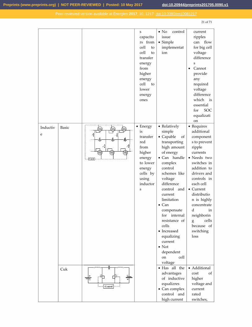
Inductiv
e
Basic • Energy is transferred from higher energy to lower energy cells by using inductors
• Relatively simple
• Capable of transporting high amount of energy
• Can handle complex control schemes like voltage difference control and current limitation
• Can compensate for internal resistance of cells
• Increased equalizing current
• Not dependent on cell voltage
• Requires additional components to prevent ripple currents
• Needs two switches in addition to drivers and controls in each cell
• Current distribution is highly concentrated in neighboring cells because of switching loss
Cuk • Has all the advantages of inductive equalizres
• Can complex control and high current
• Additional cost of higher voltage and current rated switches,
Preprints (www.preprints.org) | NOT PEER-REVIEWED | Posted: 10 May 2017 doi:10.20944/preprints201705.0090.v1
Peer-reviewed version available at Energies 2017, 10, 1217; doi:10.3390/en10081217
22 of 71
power capacitors
• Subjected to loss caused by series capacitor
• A little less efficient than typical inductive equalizers
• Faces problems during distributing equalizing currents all over the cell string
• May need additional processing power
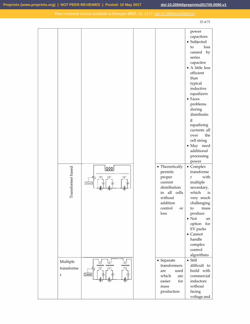
Tran
sfor
mer
bas
ed • Theoretically
permits proper current distribution in all cells without addition control or loss
• Complex transformer with multiple secondary, which is very much challenging to mass produce
• Not an option for EV packs
• Cannot handle complex control algorithms
Multiple
transforme
r
• Separate transformers are used which are easier for mass production
• Still difficult to build with commercial inductors without facing voltage and
Preprints (www.preprints.org) | NOT PEER-REVIEWED | Posted: 10 May 2017 doi:10.20944/preprints201705.0090.v1
Peer-reviewed version available at Energies 2017, 10, 1217; doi:10.3390/en10081217
23 of 71
current imbalance
Table 9: Equalizers compared; a + sign indicate an advantage whereas the – signs indicate drawbacks [47].
Lithium-Ion batteries are being used everywhere these days. It has replaced its lead-acid
counterpart and became a mature technology itself. Its popularity can be justified by the fact that best-selling EVs, for example, Nissan Leaf and Tesla Model S – all use this battery [54, 55]. Better battery technologies are discovered already, but they are not being pursued because of the exorbitant cost associated with their research and development, lithium batteries also have lots of scopes to improve [56]. So it can be said that, lithium batteries will dominate the EV scene for quite some time to come.
Table 10: Battery parameters of some current EVs [3].
Model Total energy (kWh) Usable energy
(kWh)Usable energy (%)
i3 22 18.8 85 C30 24 22.7 95
B-Class 36 28 78 e6 61.4 57 93
RAV4 41.8 35 84
4.2. Ultracapacitor (UC)
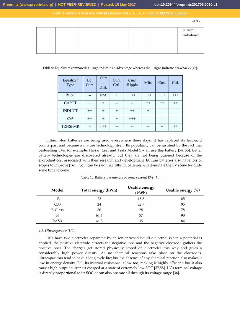
UCs have two electrodes separated by an ion-enriched liquid dielectric. When a potential is applied, the positive electrode attracts the negative ions and the negative electrode gathers the positive ones. The charges get stored physically stored on electrodes this way and gives a considerably high power density. As no chemical reactions take place on the electrodes, ultracapacitors tend to have a long cycle life; but the absence of any chemical reaction also makes it low in energy density [36]. Its internal resistance is low too, making it highly efficient, but it also causes high output current if charged at a state of extremely low SOC [57,58]. UCs terminal voltage is directly proportional to its SOC, it can also operate all through its voltage range [36].
Preprints (www.preprints.org) | NOT PEER-REVIEWED | Posted: 10 May 2017 doi:10.20944/preprints201705.0090.v1
Peer-reviewed version available at Energies 2017, 10, 1217; doi:10.3390/en10081217
24 of 71
Figure. 29: An UC cell [59].
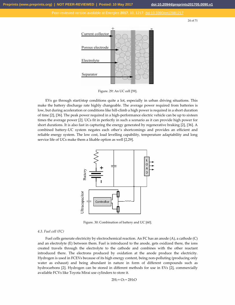
EVs go through start/stop conditions quite a lot, especially in urban driving situations. This make the battery discharge rate highly changeable. The average power required from batteries is low, but during acceleration or conditions like hill-climb a high power is required in a short duration of time [2], [36]. The peak power required in a high-performance electric vehicle can be up to sixteen times the average power [2]. UCs fit in perfectly in such a scenario as it can provide high power for short durations. It is also fast in capturing the energy generated by regenerative braking [2], [36]. A combined battery-UC system negates each other’s shortcomings and provides an efficient and reliable energy system. The low cost, load levelling capability, temperature adaptability and long service life of UCs make them a likable option as well [2,29].
Figure. 30: Combination of battery and UC [60].
4.3. Fuel cell (FC)
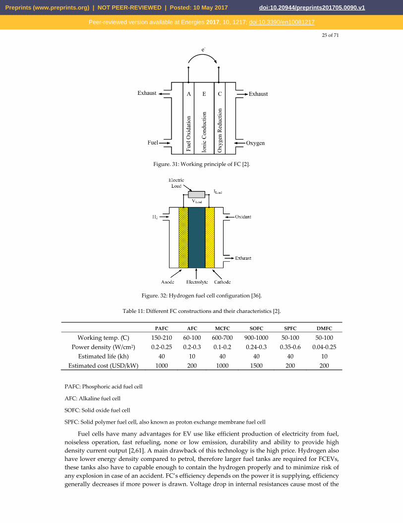
Fuel cells generate electricity by electrochemical reaction. An FC has an anode (A), a cathode (C) and an electrolyte (E) between them. Fuel is introduced to the anode, gets oxidized there, the ions created travels through the electrolyte to the cathode and combines with the other reactant introduced there. The electrons produced by oxidation at the anode produce the electricity. Hydrogen is used in FCEVs because of its high energy content, being non-polluting (producing only water as exhaust) and being abundant in nature in form of different compounds such as hydrocarbons [2]. Hydrogen can be stored in different methods for use in EVs [2], commercially available FCVs like Toyota Mirai use cylinders to store it.
2H2 + O2 = 2H2O
Preprints (www.preprints.org) | NOT PEER-REVIEWED | Posted: 10 May 2017 doi:10.20944/preprints201705.0090.v1
Peer-reviewed version available at Energies 2017, 10, 1217; doi:10.3390/en10081217
25 of 71
Figure. 31: Working principle of FC [2].
Figure. 32: Hydrogen fuel cell configuration [36].
Table 11: Different FC constructions and their characteristics [2].
PAFC AFC MCFC SOFC SPFC DMFC
Working temp. (C) 150-210 60-100 600-700 900-1000 50-100 50-100 Power density (W/cm2) 0.2-0.25 0.2-0.3 0.1-0.2 0.24-0.3 0.35-0.6 0.04-0.25
Estimated life (kh) 40 10 40 40 40 10 Estimated cost (USD/kW) 1000 200 1000 1500 200 200
PAFC: Phosphoric acid fuel cell
AFC: Alkaline fuel cell
SOFC: Solid oxide fuel cell
SPFC: Solid polymer fuel cell, also known as proton exchange membrane fuel cell
Fuel cells have many advantages for EV use like efficient production of electricity from fuel, noiseless operation, fast refueling, none or low emission, durability and ability to provide high density current output [2,61]. A main drawback of this technology is the high price. Hydrogen also have lower energy density compared to petrol, therefore larger fuel tanks are required for FCEVs, these tanks also have to capable enough to contain the hydrogen properly and to minimize risk of any explosion in case of an accident. FC’s efficiency depends on the power it is supplying, efficiency generally decreases if more power is drawn. Voltage drop in internal resistances cause most of the
Preprints (www.preprints.org) | NOT PEER-REVIEWED | Posted: 10 May 2017 doi:10.20944/preprints201705.0090.v1
Peer-reviewed version available at Energies 2017, 10, 1217; doi:10.3390/en10081217
26 of 71
losses. Response time of FCs is comparatively higher to UCs or batteries [36]. Because of these reasons, another storage is used alongside FC, like battery or UC. Toyota Mirai uses batteries to power its motor, the FC is used to charge the batteries. The batteries receive the power reproduced by regenerative braking as well. This combination provides more flexibility as the batteries do not need to be charged, only the fuel for the FC has to be replenished and it takes far less time than recharging the batteries.
4.4. Flywheel:
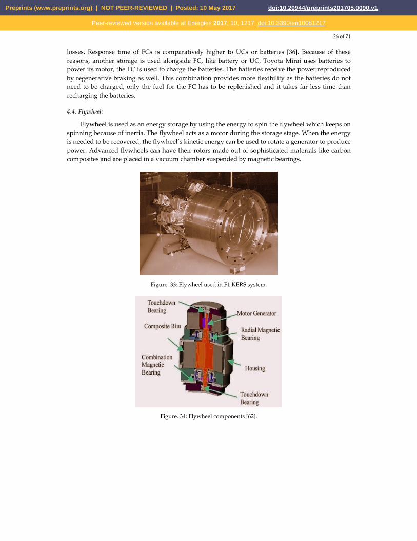
Flywheel is used as an energy storage by using the energy to spin the flywheel which keeps on spinning because of inertia. The flywheel acts as a motor during the storage stage. When the energy is needed to be recovered, the flywheel’s kinetic energy can be used to rotate a generator to produce power. Advanced flywheels can have their rotors made out of sophisticated materials like carbon composites and are placed in a vacuum chamber suspended by magnetic bearings.
Figure. 33: Flywheel used in F1 KERS system.
Figure. 34: Flywheel components [62].
Preprints (www.preprints.org) | NOT PEER-REVIEWED | Posted: 10 May 2017 doi:10.20944/preprints201705.0090.v1
Peer-reviewed version available at Energies 2017, 10, 1217; doi:10.3390/en10081217
27 of 71
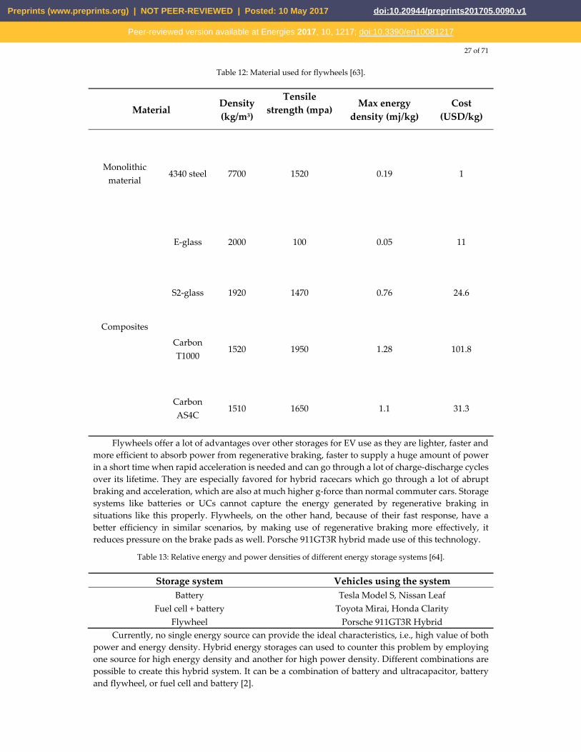
Table 12: Material used for flywheels [63].
Material Density(kg/m3)
Tensile strength (mpa)
Max energy density (mj/kg)
Cost (USD/kg)
Monolithic material
4340 steel 7700 1520 0.19 1
Composites
E-glass 2000 100 0.05 11
S2-glass 1920 1470 0.76 24.6
Carbon T1000
1520 1950 1.28 101.8
Carbon AS4C
1510 1650 1.1 31.3
Flywheels offer a lot of advantages over other storages for EV use as they are lighter, faster and more efficient to absorb power from regenerative braking, faster to supply a huge amount of power in a short time when rapid acceleration is needed and can go through a lot of charge-discharge cycles over its lifetime. They are especially favored for hybrid racecars which go through a lot of abrupt braking and acceleration, which are also at much higher g-force than normal commuter cars. Storage systems like batteries or UCs cannot capture the energy generated by regenerative braking in situations like this properly. Flywheels, on the other hand, because of their fast response, have a better efficiency in similar scenarios, by making use of regenerative braking more effectively, it reduces pressure on the brake pads as well. Porsche 911GT3R hybrid made use of this technology.
Table 13: Relative energy and power densities of different energy storage systems [64].
Storage system Vehicles using the system Battery Tesla Model S, Nissan Leaf
Fuel cell + battery Toyota Mirai, Honda Clarity Flywheel Porsche 911GT3R Hybrid
Currently, no single energy source can provide the ideal characteristics, i.e., high value of both power and energy density. Hybrid energy storages can used to counter this problem by employing one source for high energy density and another for high power density. Different combinations are possible to create this hybrid system. It can be a combination of battery and ultracapacitor, battery and flywheel, or fuel cell and battery [2].
Preprints (www.preprints.org) | NOT PEER-REVIEWED | Posted: 10 May 2017 doi:10.20944/preprints201705.0090.v1
Peer-reviewed version available at Energies 2017, 10, 1217; doi:10.3390/en10081217
28 of 71
5. Motors used
The propulsion system is the heart of an EV [65-70], and the electric motor sits right in the core of the system. The motor converts electrical energy that it gets from the battery into mechanical energy which enable the vehicle to move. It also acts as a generator during regenerative action which sends energy back to the energy source. Based on their requirement, EVs can have different numbers of motors. Toyota Prius has one, Acura NSX has three – the choice depends on the type of the vehicle and the functions it is supposed to provide. [2] and [21] listed the requirements for a motor for EV use which includes high power, high torque, wide speed range, high efficiency, reliability, robustness, reasonable cost, low noise and small size. DC motor drives demonstrate some required properties needed for EV application, but their lack in efficiency, bulky structure, lack in reliability because of the commutator or brushes present in them and associated maintenance requirement made them less attractive [2], [29]. With the advance of power electronics and control systems, different motor types emerged to meet the needs of the automotive sector, induction and permanent magnet (PM) types being the most favored ones [29,21,71].
5.1. Brushed DC Motor
These motors have permanent magnets (PM) to make the stator, rotors have brushes to provide supply to the stator. Advantages of these motors can be the ability to provide maximum torque in low speed. The disadvantages, on the other hand, are its bulky structure, low efficiency, heat generated because of the brushes and associated drop in efficiency. The heat is also difficult to remove as it is generated in the center of the rotor. Because of these reasons, brushed DC motors are not used in EVs any more [71].
5.2. Permanent Magnet Brushless DC Motor (BLDC)
The rotor of this motor is made of PM (most commonly NdFeB [2]), the stator is provided an AC supply from a DC source through an inverter. As there are no windings in the rotor, rotor copper loss is absent which makes it more efficient than induction motors. This motor is also lighter, smaller, better at dissipating heat (as it is generated in the stator), more reliable, has more torque density and specific power [2].But because of its restrained field-weakening ability, the constant power range is quite short. The torque also decreases with increased speed because of back EMF generated in the stator windings. The use of PM increases the cost as well [29,71]. However, enhancement of speed range and better overall efficiency is possible with additional field windings [2,72]. Such arrangements are often dubbed as PM hybrid motors because of the presence of both PM and field windings. But such arrangements too are restrained by complexity of structure, the speed ratio is not enough to meet the needs of EV use, off roaders specifically [29]. PM hybrid motor can also be constructed using a combination of reluctance motor and PM motor. Controlling the conduction angle of the power converter can improve the efficiency of PM BLDCs as well as speed range, reaching as high as four times the base speed, though the efficiency may decrease at very high speed resulting from demagnetization of PM [2].
Other than the PM hybrid configurations, PM BLDCs can be buried magnet mounted – which can provide more air gap flux density, or surface magnet mounted – which require less amount of magnet. BLDCs are useful for use in small cars requiring power of maximum 60kW [73].
Preprints (www.preprints.org) | NOT PEER-REVIEWED | Posted: 10 May 2017 doi:10.20944/preprints201705.0090.v1
Peer-reviewed version available at Energies 2017, 10, 1217; doi:10.3390/en10081217
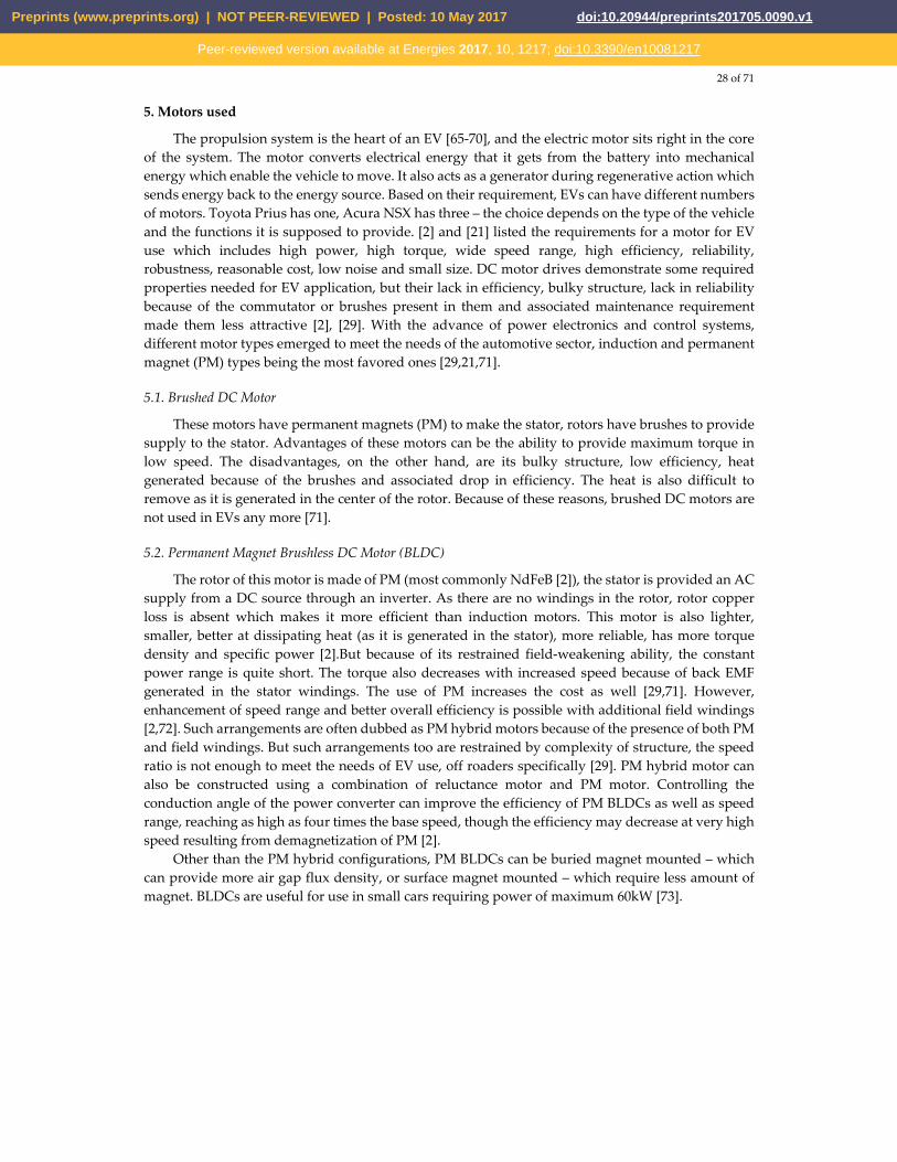
29 of 71
Figure. 35: Characteristics of Permanent Magnet Brushless DC Motor.
5.3. Permanent Magnet Synchronous Motor (PMSM)
These machines are one of the most advanced ones, capable of being operated at a range of speeds without the need of any gear system. This feature makes these motors more efficient and compact. This configuration is also very suitable for in-wheel applications, as it is capable of providing high torque, even at very low speeds. PMSMs with an outer rotor is also possible to construct without the need of bearings for the rotor. But these machines’ only notable disadvantage also comes in during in-wheel operations where a huge iron loss is faced at high speeds, making the system unstable [74]. NdFeB PMs are used for PMSMs for high energy density. The flux linkages in the air-gap are sinusoidal in nature, therefore, these motors are controllable by sinusoidal voltage supplies and vector control [71]. PMSM is the most used motor in the BEVs available currently, at least 26 vehicle models use this motor technology [3].
5.4. Induction Motor (IM)
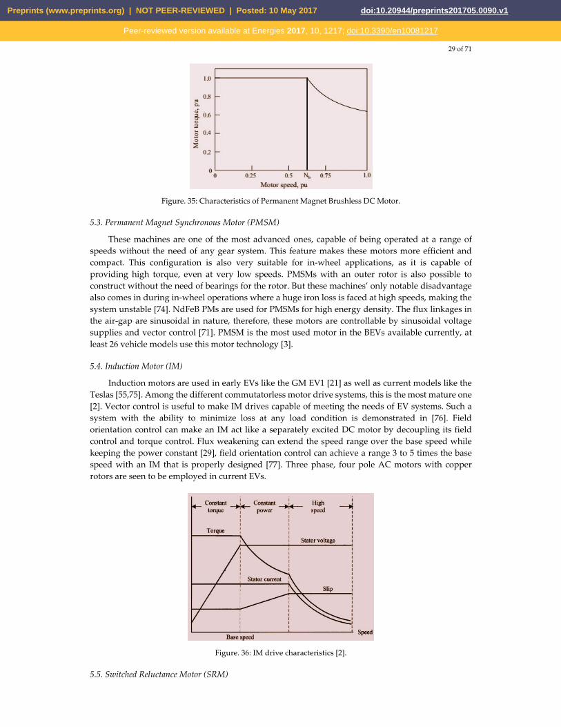
Induction motors are used in early EVs like the GM EV1 [21] as well as current models like the Teslas [55,75]. Among the different commutatorless motor drive systems, this is the most mature one [2]. Vector control is useful to make IM drives capable of meeting the needs of EV systems. Such a system with the ability to minimize loss at any load condition is demonstrated in [76]. Field orientation control can make an IM act like a separately excited DC motor by decoupling its field control and torque control. Flux weakening can extend the speed range over the base speed while keeping the power constant [29], field orientation control can achieve a range 3 to 5 times the base speed with an IM that is properly designed [77]. Three phase, four pole AC motors with copper rotors are seen to be employed in current EVs.
Figure. 36: IM drive characteristics [2].
5.5. Switched Reluctance Motor (SRM)
Preprints (www.preprints.org) | NOT PEER-REVIEWED | Posted: 10 May 2017 doi:10.20944/preprints201705.0090.v1
Peer-reviewed version available at Energies 2017, 10, 1217; doi:10.3390/en10081217
30 of 71
SRMs, also known as doubly salient motor (because of having salient poles both in the stator and the rotor) are synchronous motors driven by unipolar inverter-generated current. They demonstrate simple and robust mechanical construction, low cost, high-speed, less chance of hazard, inherent long constant power range and high power density useful for EV application. PM is not required for such motors and that facilitates enhanced reliability along with fault tolerance. On the downside, they are very noisy because of the variable torque nature, have low efficiency, larger in size and weight when compared to PM machines. Though such machines have a simple construction, their design and control are not easy resulting from fringe effect of slots and poles and high saturation of the pole-tips [2,21,29,71]. Because of such drawbacks, these machines did not advance as much as the PM or induction machines. However, because of the high cost rare-rare earth materials needed in PM machines, interest in SRMs are increasing. Advanced SRMs like the one demonstrated by Nidec in 2012 had almost interior permanent machine (IPM)-like performance, with a low cost. Reducing the noise and torque ripple are the main concerns in researches associated with SRMs [21]. One of the configurations that came out of these researches uses a dual stator system, which provides low inertia and noise, superior torque density and increased speed-range compared to conventional SRMs [78], [79]. Design by finite element analysis can be employed to reduce the total loss [80], control by fuzzy sliding mode can also be employed to reduce control chattering and motor nonlinearity management [81].
5.6. Synchronous Reluctance Motor (SynRM)
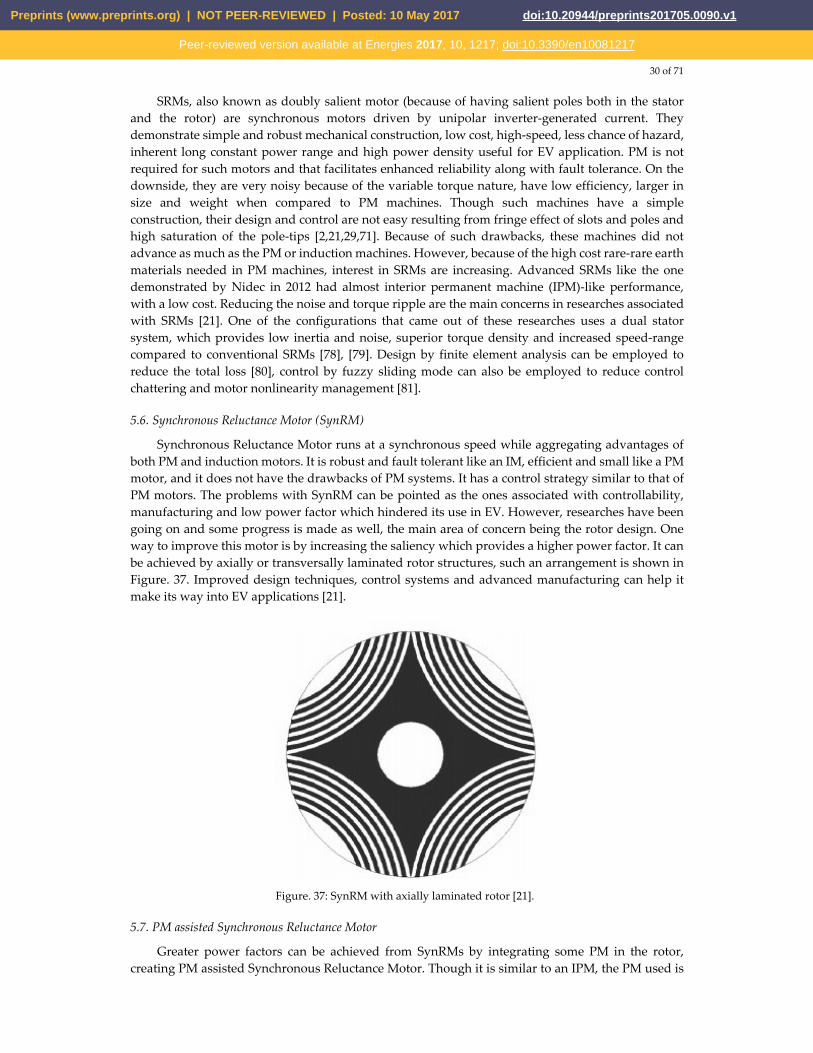
Synchronous Reluctance Motor runs at a synchronous speed while aggregating advantages of both PM and induction motors. It is robust and fault tolerant like an IM, efficient and small like a PM motor, and it does not have the drawbacks of PM systems. It has a control strategy similar to that of PM motors. The problems with SynRM can be pointed as the ones associated with controllability, manufacturing and low power factor which hindered its use in EV. However, researches have been going on and some progress is made as well, the main area of concern being the rotor design. One way to improve this motor is by increasing the saliency which provides a higher power factor. It can be achieved by axially or transversally laminated rotor structures, such an arrangement is shown in Figure. 37. Improved design techniques, control systems and advanced manufacturing can help it make its way into EV applications [21].
Figure. 37: SynRM with axially laminated rotor [21].
5.7. PM assisted Synchronous Reluctance Motor
Greater power factors can be achieved from SynRMs by integrating some PM in the rotor, creating PM assisted Synchronous Reluctance Motor. Though it is similar to an IPM, the PM used is
Preprints (www.preprints.org) | NOT PEER-REVIEWED | Posted: 10 May 2017 doi:10.20944/preprints201705.0090.v1
Peer-reviewed version available at Energies 2017, 10, 1217; doi:10.3390/en10081217
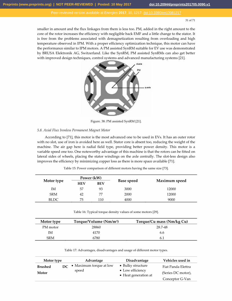
31 of 71
smaller in amount and the flux linkages from them is less too. PM, added in the right amount to the core of the rotor increases the efficiency with negligible back EMF and a little change to the stator. It is free from the problems associated with demagnetization resulting from overloading and high temperature observed in IPM. With a proper efficiency optimization technique, this motor can have the performance similar to IPM motors. A PM assisted SynRM suitable for EV use was demonstrated by BRUSA Elektronik AG, Switzerland. Like the SynRM, PM assisted SynRMs can also get better with improved design techniques, control systems and advanced manufacturing systems [21].
Figure. 38: PM assisted SynRM [21].
5.8. Axial Flux Ironless Permanent Magnet Motor
According to [71], this motor is the most advanced one to be used in EVs. It has an outer rotor with no slot, use of iron is avoided here as well. Stator core is absent too, reducing the weight of the machine. The air gap here is radial field type, providing better power density. This motor is a variable speed one too. One noteworthy advantage of this machine is that the rotors can be fitted on lateral sides of wheels, placing the stator windings on the axle centrally. The slot-less design also improves the efficiency by minimizing copper loss as there is more space available [71].
Table 15: Power comparison of different motors having the same size [73].
Motor type Power (kW)
Base speed Maximum speed HEV BEV
IM 57 93 3000 12000 SRM 42 77 2000 12000
BLDC 75 110 4000 9000
Table 16: Typical torque density values of some motors [29].
Motor type Torque/Volume (Nm/m3) Torque/Cu mass (Nm/kg Cu)PM motor 28860 28.7-48
IM 4170 6.6 SRM 6780 6.1
Table 17: Advantages, disadvantages and usage of different motor types.
Motor type Advantage Disadvantage Vehicles used in
Brushed DC
Motor
• Maximum torque at low speed
• Bulky structure • Low efficiency • Heat generation at
Fiat Panda Elettra
(Series DC motor),
Conceptor G-Van
Preprints (www.preprints.org) | NOT PEER-REVIEWED | Posted: 10 May 2017 doi:10.20944/preprints201705.0090.v1
Peer-reviewed version available at Energies 2017, 10, 1217; doi:10.3390/en10081217

32 of 71
brushes (Separately excited DC
motor)
Permanent
Magnet Brushless
DC Motor (BLDC)
• No rotor copper loss • More efficiency than
induction motors • Lighter • Smaller • Better heat dissipation • More reliability • More torque density • More specific power
• Short constant power range
• Decreased torque with increase in speed
• High cost because of PM
Toyota Prius (2005)
Permanent
Magnet
Synchronous
Motor (PMSM)
• Operable in different speed ranges without using gear systems
• Efficient • Compact • Suitable for in-wheel
application • High torque even at very
low speeds
• Huge iron loss at high speeds during in-wheel operation
Toyota Prius, Nissan
Leaf, Soul EV
Induction Motor
(IM)
• The most mature commutatorless motor drive system
• Can be operated like a separately excited DC motor by employing field orientation control
Tesla Model S, Tesla
Model X, Toyota
RAV4, GM EV1
Switched
Reluctance Motor
(SRM)
• Simple and robust construction
• Low cost • High speed • Less chance of hazard • Long constant power
range • High power density
• Very noisy • Low efficiency • Larger and heavier
than PM machines • Complex design
and control
Chloride Lucas
Synchronous
Reluctance Motor
(SynRM)
• Robust • Fault tolerant • Efficient • Small
• Problems in controllability and manufacturing
• Low power factor
PM assisted
Synchronous
Reluctance Motor
• Greater power factor than SynRMs
• Free from demagnetizing problems observed in IPM
BMW i3
Axial Flux Ironless
Permanent
Magnet Motor
• No iron used in outer rotor
• No stator core • Lightweight • Better power density • Minimized copper loss • Better efficiency • Variable speed machine
Renovo Coupe
Preprints (www.preprints.org) | NOT PEER-REVIEWED | Posted: 10 May 2017 doi:10.20944/preprints201705.0090.v1
Peer-reviewed version available at Energies 2017, 10, 1217; doi:10.3390/en10081217
33 of 71
• Rotor is capable of being fitted to the lateral side of the wheel
6. Charging systems
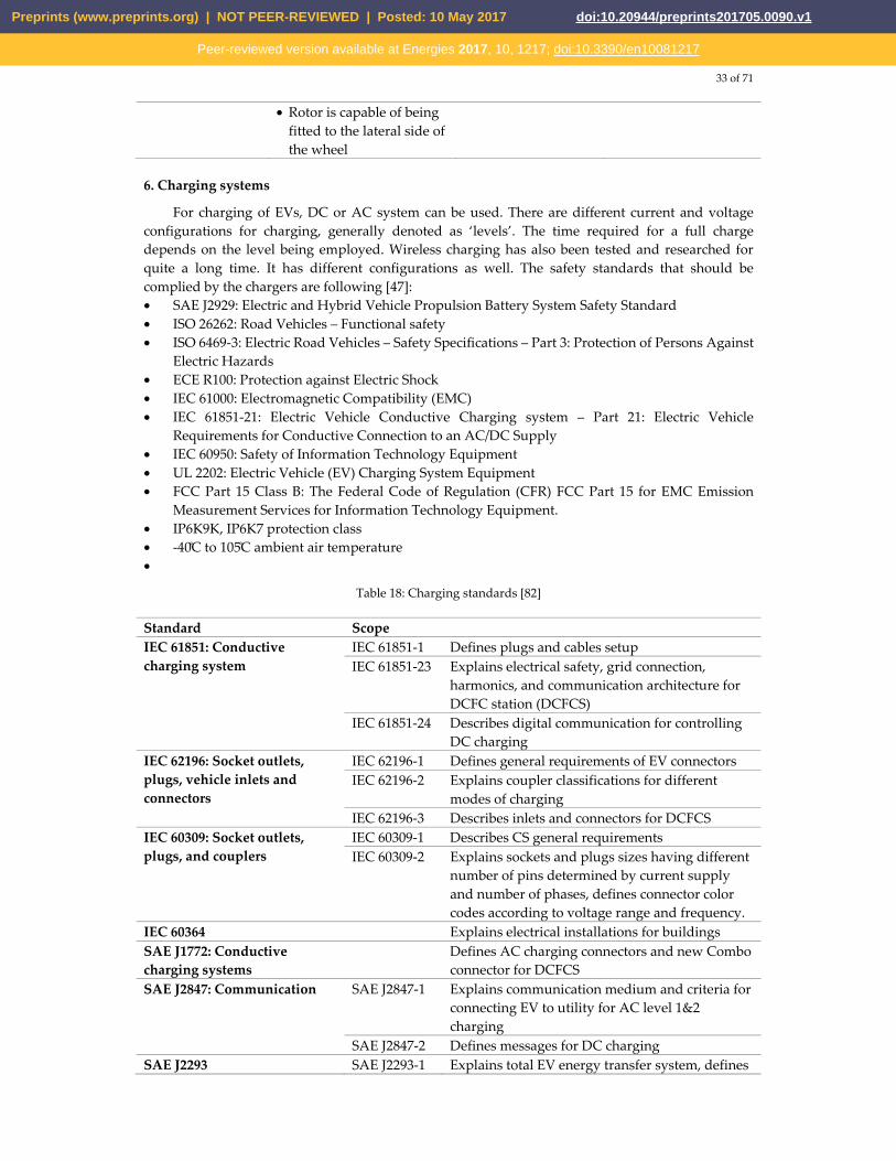
For charging of EVs, DC or AC system can be used. There are different current and voltage configurations for charging, generally denoted as ‘levels’. The time required for a full charge depends on the level being employed. Wireless charging has also been tested and researched for quite a long time. It has different configurations as well. The safety standards that should be complied by the chargers are following [47]: • SAE J2929: Electric and Hybrid Vehicle Propulsion Battery System Safety Standard • ISO 26262: Road Vehicles – Functional safety • ISO 6469-3: Electric Road Vehicles – Safety Specifications – Part 3: Protection of Persons Against
Electric Hazards • ECE R100: Protection against Electric Shock • IEC 61000: Electromagnetic Compatibility (EMC) • IEC 61851-21: Electric Vehicle Conductive Charging system – Part 21: Electric Vehicle
Requirements for Conductive Connection to an AC/DC Supply • IEC 60950: Safety of Information Technology Equipment • UL 2202: Electric Vehicle (EV) Charging System Equipment • FCC Part 15 Class B: The Federal Code of Regulation (CFR) FCC Part 15 for EMC Emission
Measurement Services for Information Technology Equipment. • IP6K9K, IP6K7 protection class • -40C to 105C ambient air temperature •
Table 18: Charging standards [82]
Standard ScopeIEC 61851: Conductive charging system
IEC 61851-1 Defines plugs and cables setup IEC 61851-23 Explains electrical safety, grid connection,
harmonics, and communication architecture for DCFC station (DCFCS)
IEC 61851-24 Describes digital communication for controlling DC charging
IEC 62196: Socket outlets, plugs, vehicle inlets and connectors
IEC 62196-1 Defines general requirements of EV connectors IEC 62196-2 Explains coupler classifications for different
modes of charging IEC 62196-3 Describes inlets and connectors for DCFCS
IEC 60309: Socket outlets, plugs, and couplers
IEC 60309-1 Describes CS general requirements IEC 60309-2 Explains sockets and plugs sizes having different
number of pins determined by current supply and number of phases, defines connector color codes according to voltage range and frequency.
IEC 60364 Explains electrical installations for buildings SAE J1772: Conductive charging systems
Defines AC charging connectors and new Combo connector for DCFCS
SAE J2847: Communication SAE J2847-1 Explains communication medium and criteria for connecting EV to utility for AC level 1&2 charging
SAE J2847-2 Defines messages for DC charging SAE J2293 SAE J2293-1 Explains total EV energy transfer system, defines
Preprints (www.preprints.org) | NOT PEER-REVIEWED | Posted: 10 May 2017 doi:10.20944/preprints201705.0090.v1
Peer-reviewed version available at Energies 2017, 10, 1217; doi:10.3390/en10081217
34 of 71
requirements for EVSE for different system architectures
SAE J2344 Defines EV safety guidelines SAE J2954: Inductive charging Being developed
The charging systems can be described as following:
6.1. AC charging
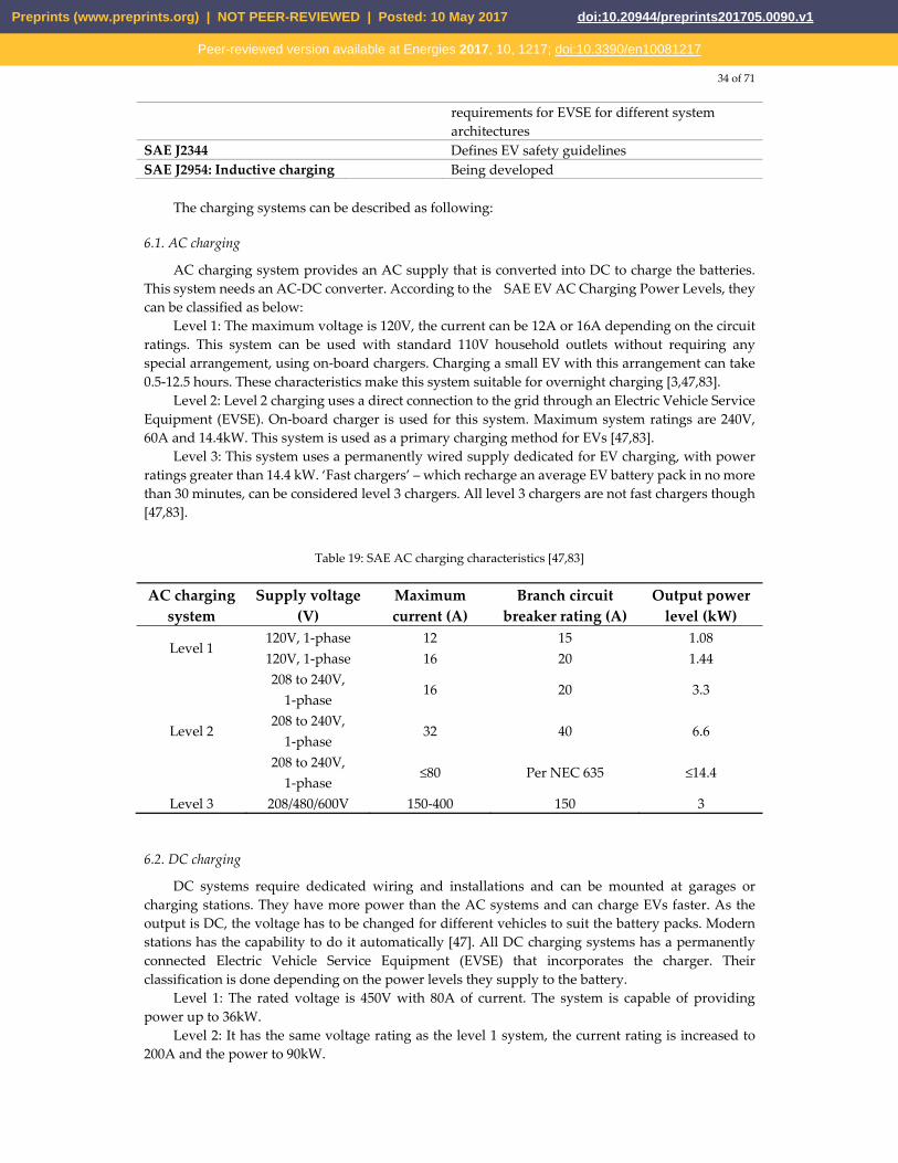
AC charging system provides an AC supply that is converted into DC to charge the batteries. This system needs an AC-DC converter. According to the SAE EV AC Charging Power Levels, they can be classified as below:
Level 1: The maximum voltage is 120V, the current can be 12A or 16A depending on the circuit ratings. This system can be used with standard 110V household outlets without requiring any special arrangement, using on-board chargers. Charging a small EV with this arrangement can take 0.5-12.5 hours. These characteristics make this system suitable for overnight charging [3,47,83].
Level 2: Level 2 charging uses a direct connection to the grid through an Electric Vehicle Service Equipment (EVSE). On-board charger is used for this system. Maximum system ratings are 240V, 60A and 14.4kW. This system is used as a primary charging method for EVs [47,83].
Level 3: This system uses a permanently wired supply dedicated for EV charging, with power ratings greater than 14.4 kW. ‘Fast chargers’ – which recharge an average EV battery pack in no more than 30 minutes, can be considered level 3 chargers. All level 3 chargers are not fast chargers though [47,83].
Table 19: SAE AC charging characteristics [47,83]
AC charging system
Supply voltage (V)
Maximum current (A)
Branch circuit breaker rating (A)
Output power level (kW)
Level 1 120V, 1-phase 12 15 1.08 120V, 1-phase 16 20 1.44
Level 2
208 to 240V, 1-phase
16 20 3.3
208 to 240V, 1-phase
32 40 6.6
208 to 240V, 1-phase
≤80 Per NEC 635 ≤14.4
Level 3 208/480/600V 150-400 150 3
6.2. DC charging
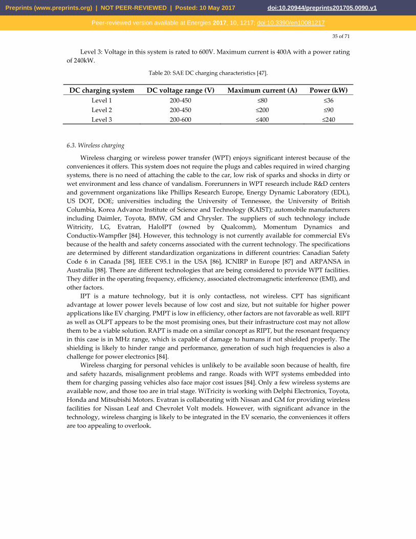
DC systems require dedicated wiring and installations and can be mounted at garages or charging stations. They have more power than the AC systems and can charge EVs faster. As the output is DC, the voltage has to be changed for different vehicles to suit the battery packs. Modern stations has the capability to do it automatically [47]. All DC charging systems has a permanently connected Electric Vehicle Service Equipment (EVSE) that incorporates the charger. Their classification is done depending on the power levels they supply to the battery.
Level 1: The rated voltage is 450V with 80A of current. The system is capable of providing power up to 36kW.
Level 2: It has the same voltage rating as the level 1 system, the current rating is increased to 200A and the power to 90kW.
Preprints (www.preprints.org) | NOT PEER-REVIEWED | Posted: 10 May 2017 doi:10.20944/preprints201705.0090.v1
Peer-reviewed version available at Energies 2017, 10, 1217; doi:10.3390/en10081217
35 of 71
Level 3: Voltage in this system is rated to 600V. Maximum current is 400A with a power rating of 240kW.
Table 20: SAE DC charging characteristics [47].
DC charging system DC voltage range (V) Maximum current (A) Power (kW)Level 1 200-450 ≤80 ≤36 Level 2 200-450 ≤200 ≤90 Level 3 200-600 ≤400 ≤240
6.3. Wireless charging
Wireless charging or wireless power transfer (WPT) enjoys significant interest because of the conveniences it offers. This system does not require the plugs and cables required in wired charging systems, there is no need of attaching the cable to the car, low risk of sparks and shocks in dirty or wet environment and less chance of vandalism. Forerunners in WPT research include R&D centers and government organizations like Phillips Research Europe, Energy Dynamic Laboratory (EDL), US DOT, DOE; universities including the University of Tennessee, the University of British Columbia, Korea Advance Institute of Science and Technology (KAIST); automobile manufacturers including Daimler, Toyota, BMW, GM and Chrysler. The suppliers of such technology include Witricity, LG, Evatran, HaloIPT (owned by Qualcomm), Momentum Dynamics and Conductix-Wampfler [84]. However, this technology is not currently available for commercial EVs because of the health and safety concerns associated with the current technology. The specifications are determined by different standardization organizations in different countries: Canadian Safety Code 6 in Canada [58], IEEE C95.1 in the USA [86], ICNIRP in Europe [87] and ARPANSA in Australia [88]. There are different technologies that are being considered to provide WPT facilities. They differ in the operating frequency, efficiency, associated electromagnetic interference (EMI), and other factors.
IPT is a mature technology, but it is only contactless, not wireless. CPT has significant advantage at lower power levels because of low cost and size, but not suitable for higher power applications like EV charging. PMPT is low in efficiency, other factors are not favorable as well. RIPT as well as OLPT appears to be the most promising ones, but their infrastructure cost may not allow them to be a viable solution. RAPT is made on a similar concept as RIPT, but the resonant frequency in this case is in MHz range, which is capable of damage to humans if not shielded properly. The shielding is likely to hinder range and performance, generation of such high frequencies is also a challenge for power electronics [84].
Wireless charging for personal vehicles is unlikely to be available soon because of health, fire and safety hazards, misalignment problems and range. Roads with WPT systems embedded into them for charging passing vehicles also face major cost issues [84]. Only a few wireless systems are available now, and those too are in trial stage. WiTricity is working with Delphi Electronics, Toyota, Honda and Mitsubishi Motors. Evatran is collaborating with Nissan and GM for providing wireless facilities for Nissan Leaf and Chevrolet Volt models. However, with significant advance in the technology, wireless charging is likely to be integrated in the EV scenario, the conveniences it offers are too appealing to overlook.
Preprints (www.preprints.org) | NOT PEER-REVIEWED | Posted: 10 May 2017 doi:10.20944/preprints201705.0090.v1
Peer-reviewed version available at Energies 2017, 10, 1217; doi:10.3390/en10081217
36 of 71
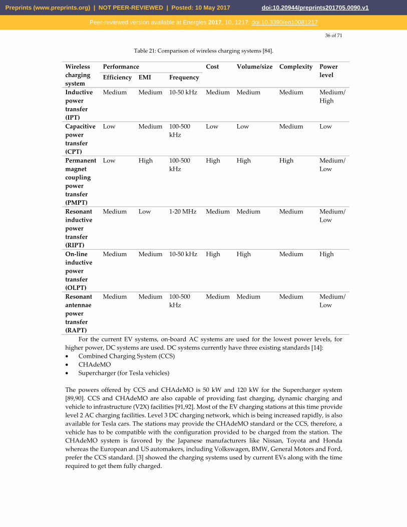
Table 21: Comparison of wireless charging systems [84].
Wireless charging system
Performance Cost Volume/size Complexity Power level Efficiency EMI Frequency
Inductive power transfer (IPT)
Medium Medium 10-50 kHz Medium Medium Medium Medium/High
Capacitive power transfer (CPT)
Low Medium 100-500 kHz
Low Low Medium Low
Permanent magnet coupling power transfer (PMPT)
Low High 100-500 kHz
High High High Medium/Low
Resonant inductive power transfer (RIPT)
Medium Low 1-20 MHz Medium Medium Medium Medium/Low
On-line inductive power transfer (OLPT)
Medium Medium 10-50 kHz High High Medium High
Resonant antennae power transfer (RAPT)
Medium Medium 100-500 kHz
Medium Medium Medium Medium/Low
For the current EV systems, on-board AC systems are used for the lowest power levels, for higher power, DC systems are used. DC systems currently have three existing standards [14]: • Combined Charging System (CCS) • CHAdeMO • Supercharger (for Tesla vehicles) The powers offered by CCS and CHAdeMO is 50 kW and 120 kW for the Supercharger system [89,90]. CCS and CHAdeMO are also capable of providing fast charging, dynamic charging and vehicle to infrastructure (V2X) facilities [91,92]. Most of the EV charging stations at this time provide level 2 AC charging facilities. Level 3 DC charging network, which is being increased rapidly, is also available for Tesla cars. The stations may provide the CHAdeMO standard or the CCS, therefore, a vehicle has to be compatible with the configuration provided to be charged from the station. The CHAdeMO system is favored by the Japanese manufacturers like Nissan, Toyota and Honda whereas the European and US automakers, including Volkswagen, BMW, General Motors and Ford, prefer the CCS standard. [3] showed the charging systems used by current EVs along with the time required to get them fully charged.
Preprints (www.preprints.org) | NOT PEER-REVIEWED | Posted: 10 May 2017 doi:10.20944/preprints201705.0090.v1
Peer-reviewed version available at Energies 2017, 10, 1217; doi:10.3390/en10081217
37 of 71
7. Power conversion techniques
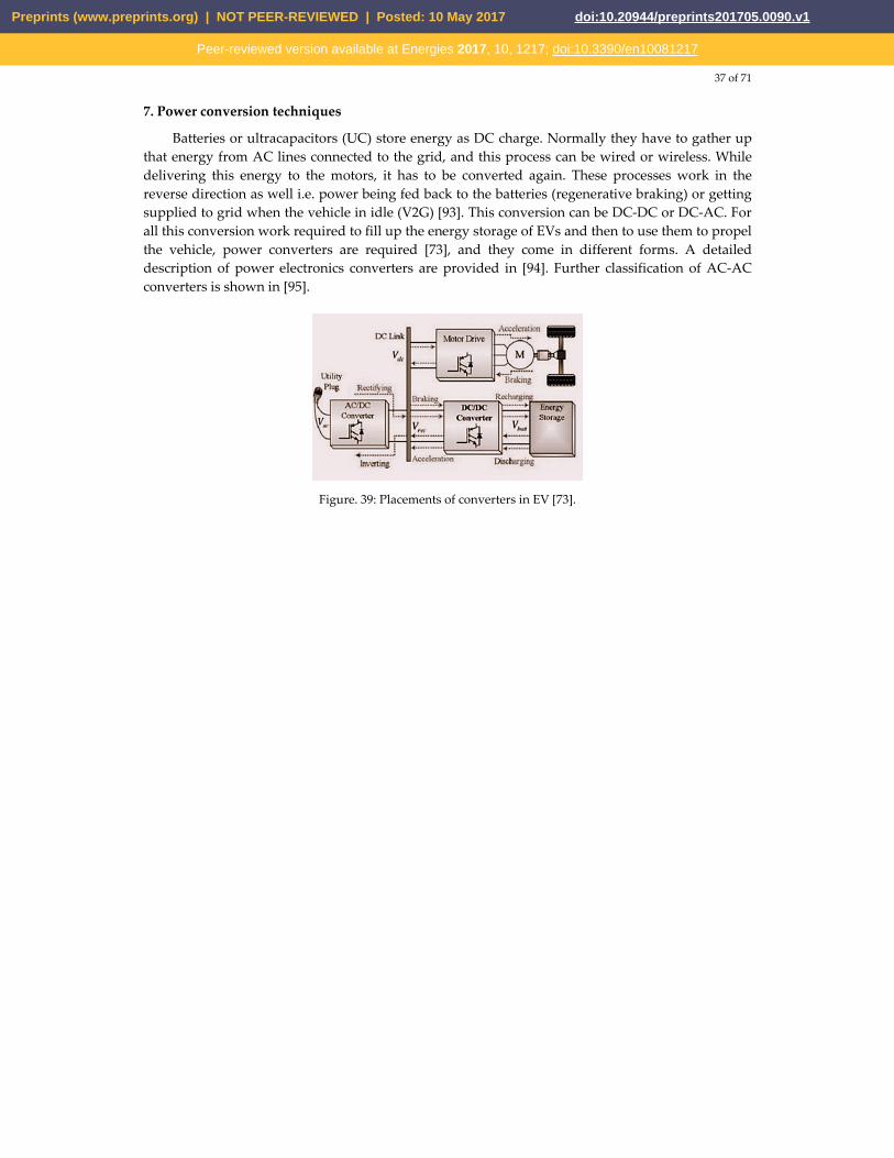
Batteries or ultracapacitors (UC) store energy as DC charge. Normally they have to gather up that energy from AC lines connected to the grid, and this process can be wired or wireless. While delivering this energy to the motors, it has to be converted again. These processes work in the reverse direction as well i.e. power being fed back to the batteries (regenerative braking) or getting supplied to grid when the vehicle in idle (V2G) [93]. This conversion can be DC-DC or DC-AC. For all this conversion work required to fill up the energy storage of EVs and then to use them to propel the vehicle, power converters are required [73], and they come in different forms. A detailed description of power electronics converters are provided in [94]. Further classification of AC-AC converters is shown in [95].
Figure. 39: Placements of converters in EV [73].
Preprints (www.preprints.org) | NOT PEER-REVIEWED | Posted: 10 May 2017 doi:10.20944/preprints201705.0090.v1
Peer-reviewed version available at Energies 2017, 10, 1217; doi:10.3390/en10081217
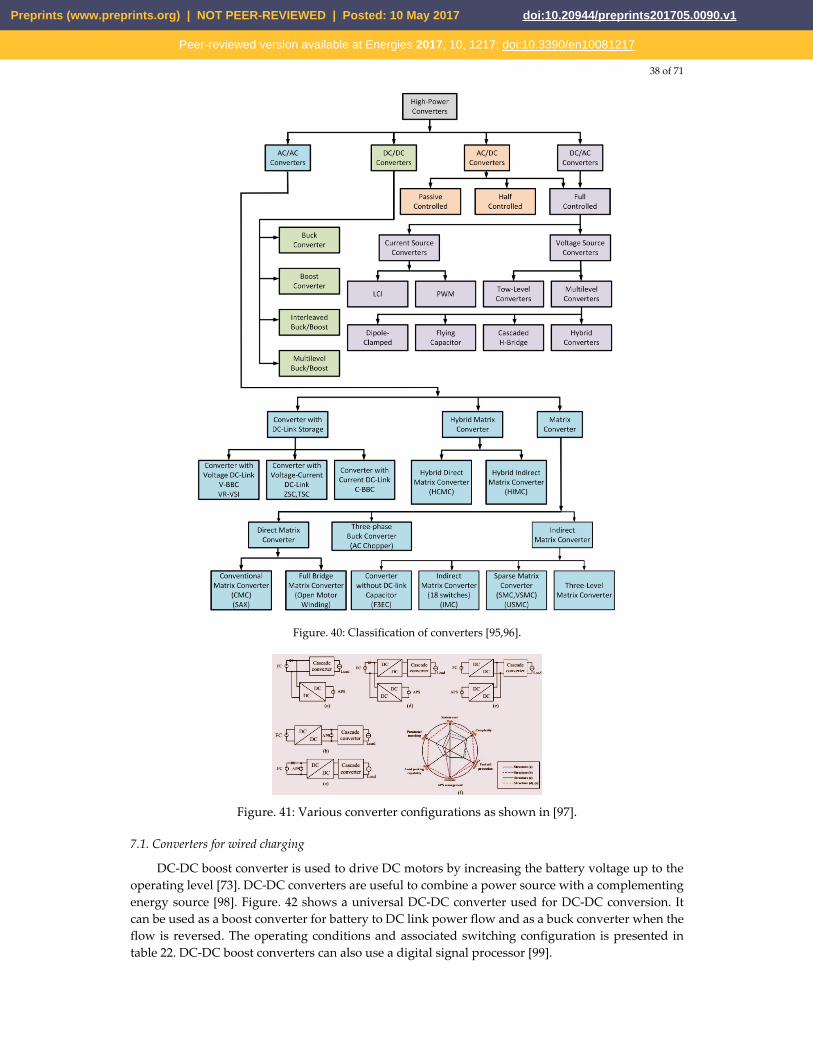
38 of 71
Figure. 40: Classification of converters [95,96].
Figure. 41: Various converter configurations as shown in [97].
7.1. Converters for wired charging
DC-DC boost converter is used to drive DC motors by increasing the battery voltage up to the operating level [73]. DC-DC converters are useful to combine a power source with a complementing energy source [98]. Figure. 42 shows a universal DC-DC converter used for DC-DC conversion. It can be used as a boost converter for battery to DC link power flow and as a buck converter when the flow is reversed. The operating conditions and associated switching configuration is presented in table 22. DC-DC boost converters can also use a digital signal processor [99].
Preprints (www.preprints.org) | NOT PEER-REVIEWED | Posted: 10 May 2017 doi:10.20944/preprints201705.0090.v1
Peer-reviewed version available at Energies 2017, 10, 1217; doi:10.3390/en10081217
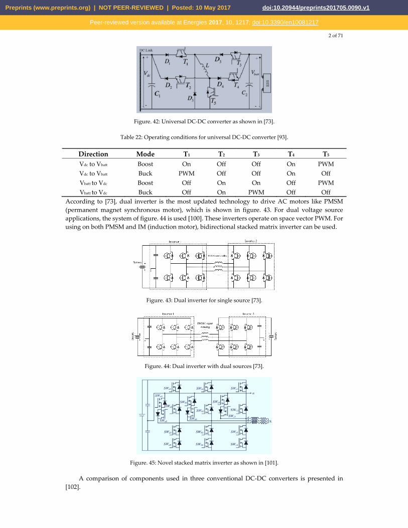
2 of 71
Figure. 42: Universal DC-DC converter as shown in [73].
Table 22: Operating conditions for universal DC-DC converter [93].
Direction Mode T1 T2 T3 T4 T5
Vdc to Vbatt Boost On Off Off On PWM Vdc to Vbatt Buck PWM Off Off On Off Vbatt to Vdc Boost Off On On Off PWM Vbatt to Vdc Buck Off On PWM Off Off
According to [73], dual inverter is the most updated technology to drive AC motors like PMSM (permanent magnet synchronous motor), which is shown in figure. 43. For dual voltage source applications, the system of figure. 44 is used [100]. These inverters operate on space vector PWM. For using on both PMSM and IM (induction motor), bidirectional stacked matrix inverter can be used.
Figure. 43: Dual inverter for single source [73].
Figure. 44: Dual inverter with dual sources [73].
Figure. 45: Novel stacked matrix inverter as shown in [101].
A comparison of components used in three conventional DC-DC converters is presented in [102].
Preprints (www.preprints.org) | NOT PEER-REVIEWED | Posted: 10 May 2017 doi:10.20944/preprints201705.0090.v1
Peer-reviewed version available at Energies 2017, 10, 1217; doi:10.3390/en10081217
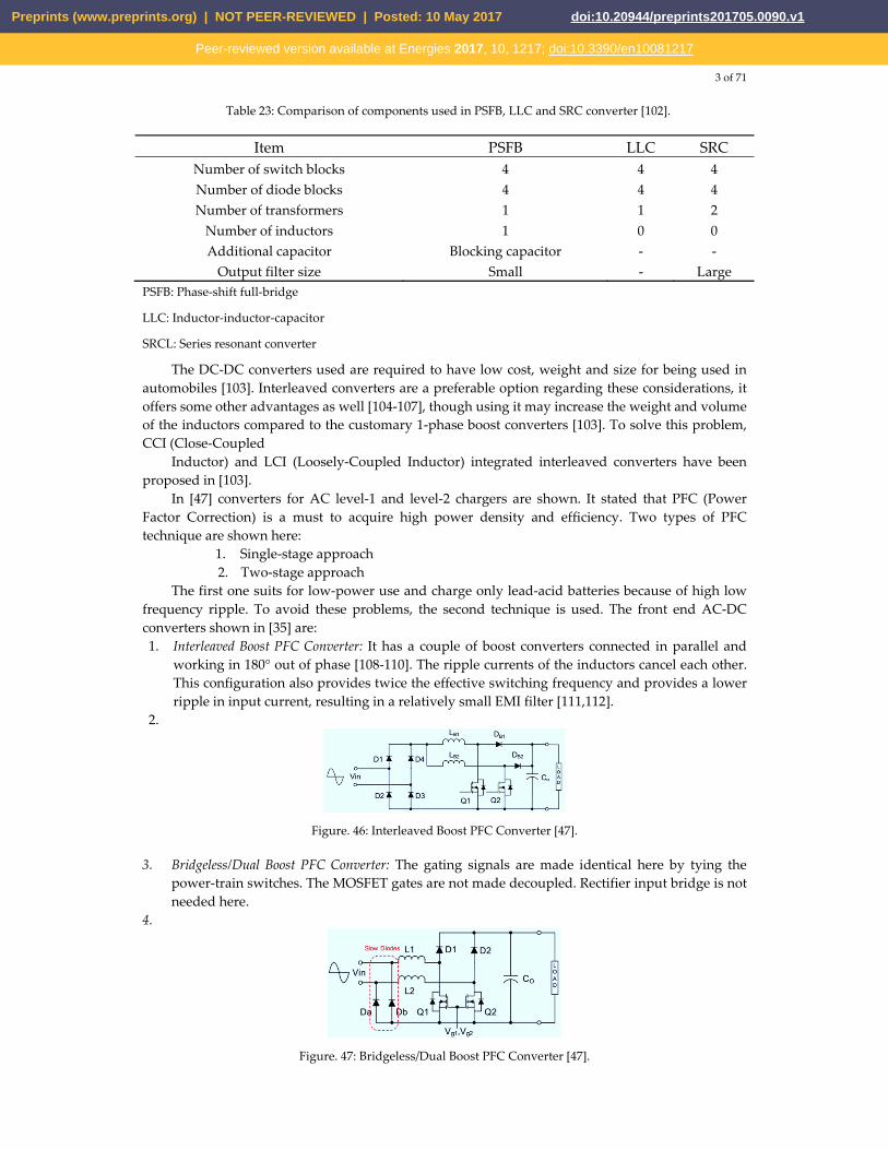
3 of 71
Table 23: Comparison of components used in PSFB, LLC and SRC converter [102].
Item PSFB LLC SRCNumber of switch blocks 4 4 4 Number of diode blocks 4 4 4 Number of transformers 1 1 2
Number of inductors 1 0 0 Additional capacitor Blocking capacitor - -
Output filter size Small - Large PSFB: Phase-shift full-bridge
LLC: Inductor-inductor-capacitor
SRCL: Series resonant converter
The DC-DC converters used are required to have low cost, weight and size for being used in automobiles [103]. Interleaved converters are a preferable option regarding these considerations, it offers some other advantages as well [104-107], though using it may increase the weight and volume of the inductors compared to the customary 1-phase boost converters [103]. To solve this problem, CCI (Close-Coupled
Inductor) and LCI (Loosely-Coupled Inductor) integrated interleaved converters have been proposed in [103].
In [47] converters for AC level-1 and level-2 chargers are shown. It stated that PFC (Power Factor Correction) is a must to acquire high power density and efficiency. Two types of PFC technique are shown here:
1. Single-stage approach 2. Two-stage approach
The first one suits for low-power use and charge only lead-acid batteries because of high low frequency ripple. To avoid these problems, the second technique is used. The front end AC-DC converters shown in [35] are: 1. Interleaved Boost PFC Converter: It has a couple of boost converters connected in parallel and
working in 180° out of phase [108-110]. The ripple currents of the inductors cancel each other. This configuration also provides twice the effective switching frequency and provides a lower ripple in input current, resulting in a relatively small EMI filter [111,112].
2.
Figure. 46: Interleaved Boost PFC Converter [47].
3. Bridgeless/Dual Boost PFC Converter: The gating signals are made identical here by tying the power-train switches. The MOSFET gates are not made decoupled. Rectifier input bridge is not needed here.
4.
Figure. 47: Bridgeless/Dual Boost PFC Converter [47].
Preprints (www.preprints.org) | NOT PEER-REVIEWED | Posted: 10 May 2017 doi:10.20944/preprints201705.0090.v1
Peer-reviewed version available at Energies 2017, 10, 1217; doi:10.3390/en10081217
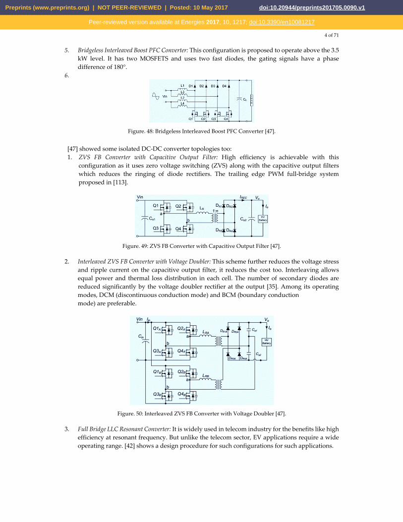
4 of 71
5. Bridgeless Interleaved Boost PFC Converter: This configuration is proposed to operate above the 3.5 kW level. It has two MOSFETS and uses two fast diodes, the gating signals have a phase difference of 180°.
6.
Figure. 48: Bridgeless Interleaved Boost PFC Converter [47].
[47] showed some isolated DC-DC converter topologies too: 1. ZVS FB Converter with Capacitive Output Filter: High efficiency is achievable with this
configuration as it uses zero voltage switching (ZVS) along with the capacitive output filters which reduces the ringing of diode rectifiers. The trailing edge PWM full-bridge system proposed in [113].
Figure. 49: ZVS FB Converter with Capacitive Output Filter [47].
2. Interleaved ZVS FB Converter with Voltage Doubler: This scheme further reduces the voltage stress and ripple current on the capacitive output filter, it reduces the cost too. Interleaving allows equal power and thermal loss distribution in each cell. The number of secondary diodes are reduced significantly by the voltage doubler rectifier at the output [35]. Among its operating modes, DCM (discontinuous conduction mode) and BCM (boundary conduction mode) are preferable.
Figure. 50: Interleaved ZVS FB Converter with Voltage Doubler [47].
3. Full Bridge LLC Resonant Converter: It is widely used in telecom industry for the benefits like high efficiency at resonant frequency. But unlike the telecom sector, EV applications require a wide operating range. [42] shows a design procedure for such configurations for such applications.
Preprints (www.preprints.org) | NOT PEER-REVIEWED | Posted: 10 May 2017 doi:10.20944/preprints201705.0090.v1
Peer-reviewed version available at Energies 2017, 10, 1217; doi:10.3390/en10081217

5 of 71
Figure. 51: Full Bridge LLC Resonant Converter [47].
[43] gathered some converter configurations used in different types of EVs.
Figure. 52: Converter placement in a pure EV [36].
Figure. 53: Cascaded converter to use in PHEV [36].
Figure. 54: PHEV using integrated converter [36].
Preprints (www.preprints.org) | NOT PEER-REVIEWED | Posted: 10 May 2017 doi:10.20944/preprints201705.0090.v1
Peer-reviewed version available at Energies 2017, 10, 1217; doi:10.3390/en10081217
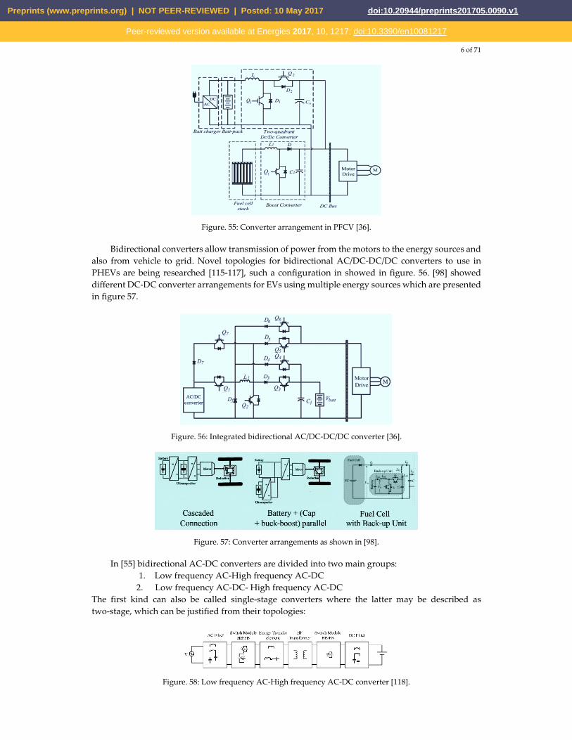
6 of 71
Figure. 55: Converter arrangement in PFCV [36].
Bidirectional converters allow transmission of power from the motors to the energy sources and also from vehicle to grid. Novel topologies for bidirectional AC/DC-DC/DC converters to use in PHEVs are being researched [115-117], such a configuration in showed in figure. 56. [98] showed different DC-DC converter arrangements for EVs using multiple energy sources which are presented in figure 57.
Figure. 56: Integrated bidirectional AC/DC-DC/DC converter [36].
Figure. 57: Converter arrangements as shown in [98].
In [55] bidirectional AC-DC converters are divided into two main groups: 1. Low frequency AC-High frequency AC-DC
2. Low frequency AC-DC- High frequency AC-DC The first kind can also be called single-stage converters where the latter may be described as two-stage, which can be justified from their topologies:
Figure. 58: Low frequency AC-High frequency AC-DC converter [118].
Preprints (www.preprints.org) | NOT PEER-REVIEWED | Posted: 10 May 2017 doi:10.20944/preprints201705.0090.v1
Peer-reviewed version available at Energies 2017, 10, 1217; doi:10.3390/en10081217
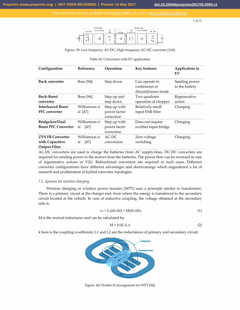
7 of 71
Figure. 59: Low frequency AC-DC- High frequency AC-DC converter [118].
Table 24: Converters with EV application.
Configuration Reference Operation Key features Application in EV
Buck converter Bose [94] Step down Can operate in continuous or discontinuous mode
Sending power to the battery
Buck-Boost converter
Bose [94] Step up and step down
Two quadrant operation of chopper
Regenerative action
Interleaved Boost PFC converter
Williamson et al. [47]
Step up with power factor correction
Relatively small input EMI filter
Charging
Bridgeless/Dual Boost PFC Converter
Williamson et al. [47]
Step up with power factor correction
Does not require rectifier input bridge
Charging
ZVS FB Converter with Capacitive Output Filter
Williamson et al. [47]
AC-DC conversion
Zero voltage switching
Charging
AC-DC converters are used to charge the batteries from AC supply-lines, DC-DC converters are required for sending power to the motors from the batteries. The power flow can be reversed in case of regenerative actions or V2G. Bidirectional converters are required in such cases. Different converter configurations have different advantages and shortcomings which engendered a lot of research and proliferation of hybrid converter topologies.
7.2. Systems for wireless charging
Wireless charging or wireless power transfer (WPT) uses a principle similar to transformer. There is a primary circuit at the charger end, from where the energy is transferred to the secondary circuit located at the vehicle. In case of inductive coupling, the voltage obtained at the secondary side is:
v2 = L2(di2/dt) + M(di1/dt), (1)
M is the mutual inductance and can be calculated by:
M = k√(L1L2) (2)
k here is the coupling co-efficient, L1 and L2 are the inductances of primary and secondary circuit.
Figure. 60: Double D arrangement for WPT [84].
Preprints (www.preprints.org) | NOT PEER-REVIEWED | Posted: 10 May 2017 doi:10.20944/preprints201705.0090.v1
Peer-reviewed version available at Energies 2017, 10, 1217; doi:10.3390/en10081217
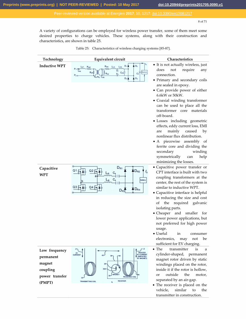
8 of 71
A variety of configurations can be employed for wireless power transfer, some of them meet some desired properties to charge vehicles. These systems, along with their construction and characteristics, are shown in table 25.
Table 25: Characteristics of wireless charging systems [85-87].
Technology Equivalent circuit Characteristics
Inductive WPT
• It is not actually wireless, just does not require any connection.
• Primary and secondary coils are sealed in epoxy.
• Can provide power of either 6.6kW or 50kW.
• Coaxial winding transformer can be used to place all the transformer core materials off-board.
• Losses including geometric effects, eddy current loss, EMI are mainly caused by nonlinear flux distribution.
• A piecewise assembly of ferrite core and dividing the secondary winding symmetrically can help minimizing the losses.
Capacitive
WPT
• Capacitive power transfer or CPT interface is built with two coupling transformers at the center, the rest of the system is similar to inductive WPT.
• Capacitive interface is helpful in reducing the size and cost of the required galvanic isolating parts.
• Cheaper and smaller for lower power applications, but not preferred for high power usage.
• Useful in consumer electronics, may not be sufficient for EV charging.
Low frequency
permanent
magnet
coupling
power transfer
(PMPT)
• The transmitter is a cylinder-shaped, permanent magnet rotor driven by static windings placed on the rotor, inside it if the rotor is hollow, or outside the motor, separated by an air-gap.
• The receiver is placed on the vehicle, similar to the transmitter in construction.
Preprints (www.preprints.org) | NOT PEER-REVIEWED | Posted: 10 May 2017 doi:10.20944/preprints201705.0090.v1
Peer-reviewed version available at Energies 2017, 10, 1217; doi:10.3390/en10081217
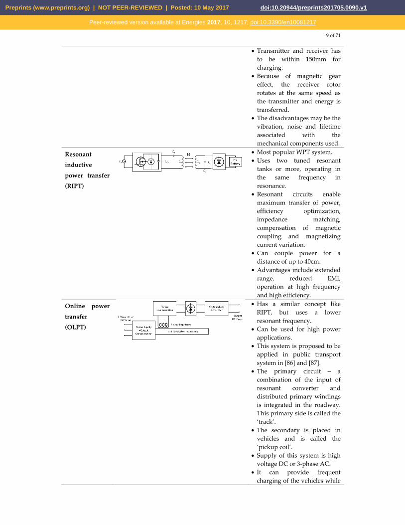
9 of 71
• Transmitter and receiver has to be within 150mm for charging.
• Because of magnetic gear effect, the receiver rotor rotates at the same speed as the transmitter and energy is transferred.
• The disadvantages may be the vibration, noise and lifetime associated with the mechanical components used.
Resonant
inductive
power transfer
(RIPT)
• Most popular WPT system. • Uses two tuned resonant
tanks or more, operating in the same frequency in resonance.
• Resonant circuits enable maximum transfer of power, efficiency optimization, impedance matching, compensation of magnetic coupling and magnetizing current variation.
• Can couple power for a distance of up to 40cm.
• Advantages include extended range, reduced EMI, operation at high frequency and high efficiency.
Online power
transfer
(OLPT)
• Has a similar concept like RIPT, but uses a lower resonant frequency.
• Can be used for high power applications.
• This system is proposed to be applied in public transport system in [86] and [87].
• The primary circuit – a combination of the input of resonant converter and distributed primary windings is integrated in the roadway. This primary side is called the ‘track’.
• The secondary is placed in vehicles and is called the ‘pickup coil’.
• Supply of this system is high voltage DC or 3-phase AC.
• It can provide frequent charging of the vehicles while
Preprints (www.preprints.org) | NOT PEER-REVIEWED | Posted: 10 May 2017 doi:10.20944/preprints201705.0090.v1
Peer-reviewed version available at Energies 2017, 10, 1217; doi:10.3390/en10081217
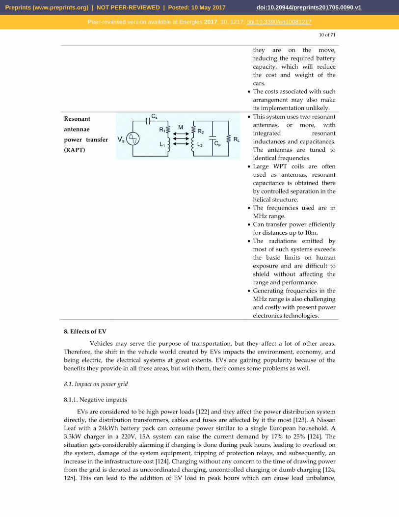
10 of 71
they are on the move, reducing the required battery capacity, which will reduce the cost and weight of the cars.
• The costs associated with such arrangement may also make its implementation unlikely.
Resonant
antennae
power transfer
(RAPT)
• This system uses two resonant antennas, or more, with integrated resonant inductances and capacitances. The antennas are tuned to identical frequencies.
• Large WPT coils are often used as antennas, resonant capacitance is obtained there by controlled separation in the helical structure.
• The frequencies used are in MHz range.
• Can transfer power efficiently for distances up to 10m.
• The radiations emitted by most of such systems exceeds the basic limits on human exposure and are difficult to shield without affecting the range and performance.
• Generating frequencies in the MHz range is also challenging and costly with present power electronics technologies.
8. Effects of EV
Vehicles may serve the purpose of transportation, but they affect a lot of other areas. Therefore, the shift in the vehicle world created by EVs impacts the environment, economy, and being electric, the electrical systems at great extents. EVs are gaining popularity because of the benefits they provide in all these areas, but with them, there comes some problems as well.
8.1. Impact on power grid
8.1.1. Negative impacts
EVs are considered to be high power loads [122] and they affect the power distribution system directly, the distribution transformers, cables and fuses are affected by it the most [123]. A Nissan Leaf with a 24kWh battery pack can consume power similar to a single European household. A 3.3kW charger in a 220V, 15A system can raise the current demand by 17% to 25% [124]. The situation gets considerably alarming if charging is done during peak hours, leading to overload on the system, damage of the system equipment, tripping of protection relays, and subsequently, an increase in the infrastructure cost [124]. Charging without any concern to the time of drawing power from the grid is denoted as uncoordinated charging, uncontrolled charging or dumb charging [124, 125]. This can lead to the addition of EV load in peak hours which can cause load unbalance,
Preprints (www.preprints.org) | NOT PEER-REVIEWED | Posted: 10 May 2017 doi:10.20944/preprints201705.0090.v1
Peer-reviewed version available at Energies 2017, 10, 1217; doi:10.3390/en10081217
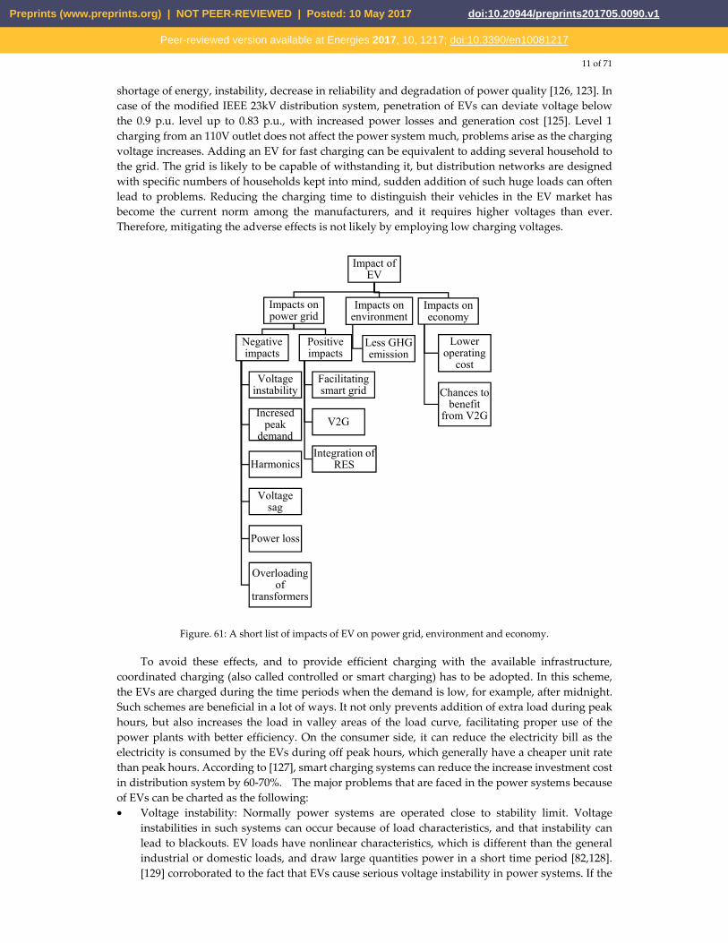
11 of 71
shortage of energy, instability, decrease in reliability and degradation of power quality [126, 123]. In case of the modified IEEE 23kV distribution system, penetration of EVs can deviate voltage below the 0.9 p.u. level up to 0.83 p.u., with increased power losses and generation cost [125]. Level 1 charging from an 110V outlet does not affect the power system much, problems arise as the charging voltage increases. Adding an EV for fast charging can be equivalent to adding several household to the grid. The grid is likely to be capable of withstanding it, but distribution networks are designed with specific numbers of households kept into mind, sudden addition of such huge loads can often lead to problems. Reducing the charging time to distinguish their vehicles in the EV market has become the current norm among the manufacturers, and it requires higher voltages than ever. Therefore, mitigating the adverse effects is not likely by employing low charging voltages.
Figure. 61: A short list of impacts of EV on power grid, environment and economy.
To avoid these effects, and to provide efficient charging with the available infrastructure, coordinated charging (also called controlled or smart charging) has to be adopted. In this scheme, the EVs are charged during the time periods when the demand is low, for example, after midnight. Such schemes are beneficial in a lot of ways. It not only prevents addition of extra load during peak hours, but also increases the load in valley areas of the load curve, facilitating proper use of the power plants with better efficiency. On the consumer side, it can reduce the electricity bill as the electricity is consumed by the EVs during off peak hours, which generally have a cheaper unit rate than peak hours. According to [127], smart charging systems can reduce the increase investment cost in distribution system by 60-70%. The major problems that are faced in the power systems because of EVs can be charted as the following: • Voltage instability: Normally power systems are operated close to stability limit. Voltage
instabilities in such systems can occur because of load characteristics, and that instability can lead to blackouts. EV loads have nonlinear characteristics, which is different than the general industrial or domestic loads, and draw large quantities power in a short time period [82,128]. [129] corroborated to the fact that EVs cause serious voltage instability in power systems. If the
Impact of EV
Impacts on power grid
Negative impacts
Voltage instability
Incresed peak
demand
Harmonics
Voltage sag
Power loss
Overloading of
transformers
Positive impacts
Facilitating smart grid
V2G
Integration of RES
Impacts on environment
Less GHG emission
Impacts on economy
Lower operating
cost
Chances to benefit
from V2G
Preprints (www.preprints.org) | NOT PEER-REVIEWED | Posted: 10 May 2017 doi:10.20944/preprints201705.0090.v1
Peer-reviewed version available at Energies 2017, 10, 1217; doi:10.3390/en10081217
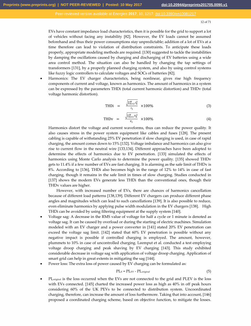
12 of 71
EVs have constant impedance load characteristics, then it is possible for the grid to support a lot of vehicles without facing any instability [82]. However, the EV loads cannot be assumed beforehand and thus their power consumptions stay unpredictable; addition of a lot of EVs at a time therefore can lead to violation of distribution constraints. To anticipate these loads properly, appropriate modeling methods are required. [130] suggested to tackle the instabilities by damping the oscillations caused by charging and discharging of EV batteries using a wide area control method. The situation can also be handled by changing the tap settings of transformers [131], by a properly planned charging system, and also by using control systems like fuzzy logic controllers to calculate voltages and SOCs of batteries [82].
• Harmonics: The EV charger characteristics, being nonlinear, gives rise high frequency components of current and voltage, known as harmonics. The amount of harmonics in a system can be expressed by the parameters THDi (total current harmonic distortion) and THDv (total voltage harmonic distortion).
THDi = ∑ ×100% (3)
THDv = ∑ ×100% (4)
Harmonics distort the voltage and current waveforms, thus can reduce the power quality. It also causes stress in the power system equipment like cables and fuses [128]. The present cabling is capable of withstanding 25% EV penetration if slow charging is used, in case of rapid charging, the amount comes down to 15% [132]. Voltage imbalance and harmonics can also give rise to current flow in the neutral wire [133,134]. Different approaches have been adopted to determine the effects of harmonics due to EV penetration. [133] simulated the effects of harmonics using Monte Carlo analysis to determine the power quality. [135] showed THDv gets to 11.4% if a few number of EVs are fast charging. It is alarming as the safe limit of THDv is 8%. According to [136], THDi also becomes high in the range of 12% to 14% in case of fast charging, though it remains in the safe limit in times of slow charging. Studies conducted in [137] shows the modern EVs generate less THDi than the conventional ones, though their THDv values are higher.
However, with increased number of EVs, there are chances of harmonics cancellation because of different load patterns [138,139]. Different EV chargers can produce different phase angles and magnitudes which can lead to such cancellations [139]. It is also possible to reduce, even eliminate harmonics by applying pulse width modulation in the EV chargers [138]. High THDi can be avoided by using filtering equipment at the supply system [140].
• Voltage sag: A decrease in the RMS value of voltage for half a cycle or 1 minute is denoted as voltage sag. It can be caused by overload or during the starting of electric machines. Simulation modeled with an EV charger and a power converter in [141] stated 20% EV penetration can exceed the voltage sag limit. [142] stated that 60% EV penetration is possible without any negative impact is possible if controlled charging is employed. The amount, however, plummets to 10% in case of uncontrolled charging. Leemput et al. conducted a test employing voltage droop charging and peak shaving by EV charging [143]. This study exhibited considerable decrease in voltage sag with application of voltage droop charging. Application of smart grid can help in great extents in mitigating the sag [144].
• Power loss: The extra loss of power caused by EV charging can be formulated as:
PLE = PLEV - PLoriginal (5)
• PLoriginal is the loss occurred when the EVs are not connected to the grid and PLEV is the loss with EVs connected. [145] charted the increased power loss as high as 40% in off peak hours considering 60% of the UK PEVs to be connected to distribution system. Uncoordinated charging, therefore, can increase the amount of loss furthermore. Taking that into account, [146] proposed a coordinated charging scheme, based on objective function, to mitigate the losses.
Preprints (www.preprints.org) | NOT PEER-REVIEWED | Posted: 10 May 2017 doi:10.20944/preprints201705.0090.v1
Peer-reviewed version available at Energies 2017, 10, 1217; doi:10.3390/en10081217
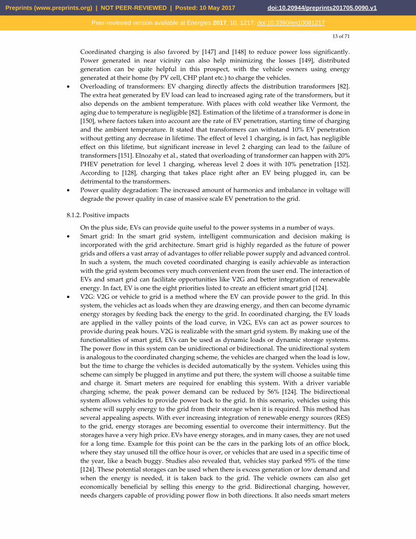
13 of 71
Coordinated charging is also favored by [147] and [148] to reduce power loss significantly. Power generated in near vicinity can also help minimizing the losses [149], distributed generation can be quite helpful in this prospect, with the vehicle owners using energy generated at their home (by PV cell, CHP plant etc.) to charge the vehicles.
• Overloading of transformers: EV charging directly affects the distribution transformers [82]. The extra heat generated by EV load can lead to increased aging rate of the transformers, but it also depends on the ambient temperature. With places with cold weather like Vermont, the aging due to temperature is negligible [82]. Estimation of the lifetime of a transformer is done in [150], where factors taken into account are the rate of EV penetration, starting time of charging and the ambient temperature. It stated that transformers can withstand 10% EV penetration without getting any decrease in lifetime. The effect of level 1 charging, is in fact, has negligible effect on this lifetime, but significant increase in level 2 charging can lead to the failure of transformers [151]. Elnozahy et al., stated that overloading of transformer can happen with 20% PHEV penetration for level 1 charging, whereas level 2 does it with 10% penetration [152]. According to [128], charging that takes place right after an EV being plugged in, can be detrimental to the transformers.
• Power quality degradation: The increased amount of harmonics and imbalance in voltage will degrade the power quality in case of massive scale EV penetration to the grid.
8.1.2. Positive impacts
On the plus side, EVs can provide quite useful to the power systems in a number of ways. • Smart grid: In the smart grid system, intelligent communication and decision making is
incorporated with the grid architecture. Smart grid is highly regarded as the future of power grids and offers a vast array of advantages to offer reliable power supply and advanced control. In such a system, the much coveted coordinated charging is easily achievable as interaction with the grid system becomes very much convenient even from the user end. The interaction of EVs and smart grid can facilitate opportunities like V2G and better integration of renewable energy. In fact, EV is one the eight priorities listed to create an efficient smart grid [124].
• V2G: V2G or vehicle to grid is a method where the EV can provide power to the grid. In this system, the vehicles act as loads when they are drawing energy, and then can become dynamic energy storages by feeding back the energy to the grid. In coordinated charging, the EV loads are applied in the valley points of the load curve, in V2G, EVs can act as power sources to provide during peak hours. V2G is realizable with the smart grid system. By making use of the functionalities of smart grid, EVs can be used as dynamic loads or dynamic storage systems. The power flow in this system can be unidirectional or bidirectional. The unidirectional system is analogous to the coordinated charging scheme, the vehicles are charged when the load is low, but the time to charge the vehicles is decided automatically by the system. Vehicles using this scheme can simply be plugged in anytime and put there, the system will choose a suitable time and charge it. Smart meters are required for enabling this system. With a driver variable charging scheme, the peak power demand can be reduced by 56% [124]. The bidirectional system allows vehicles to provide power back to the grid. In this scenario, vehicles using this scheme will supply energy to the grid from their storage when it is required. This method has several appealing aspects. With ever increasing integration of renewable energy sources (RES) to the grid, energy storages are becoming essential to overcome their intermittency. But the storages have a very high price. EVs have energy storages, and in many cases, they are not used for a long time. Example for this point can be the cars in the parking lots of an office block, where they stay unused till the office hour is over, or vehicles that are used in a specific time of the year, like a beach buggy. Studies also revealed that, vehicles stay parked 95% of the time [124]. These potential storages can be used when there is excess generation or low demand and when the energy is needed, it is taken back to the grid. The vehicle owners can also get economically beneficial by selling this energy to the grid. Bidirectional charging, however, needs chargers capable of providing power flow in both directions. It also needs smart meters
Preprints (www.preprints.org) | NOT PEER-REVIEWED | Posted: 10 May 2017 doi:10.20944/preprints201705.0090.v1
Peer-reviewed version available at Energies 2017, 10, 1217; doi:10.3390/en10081217
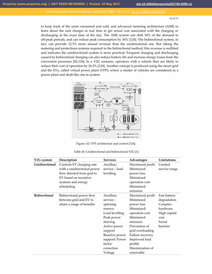
14 of 71
to keep track of the units consumed and sold, and advanced metering architecture (AMI) to learn about the unit charges in real time to get actual cost associated with the charging or discharging at the exact time of the day. The AMI system can shift 54% of the demand to off-peak periods, and can reduce peak consumption by 36% [124]. The bidirectional system, in fact, can provide 12.3% more annual revenue than the unidirectional one. But taking the metering and protections systems required in the bidirectional method, this revenue is nullified and indicates the unidirectional system is more practical. Frequent charging and discharging caused by bidirectional charging can also reduce battery life and increase energy losses from the conversion processes [82,124]. In a V2G scenario, operators with a vehicle fleet are likely to reduce their cost of operation by 26.5% [124]. Another concept is produced using the smart grid and the EVs, called virtual power plant (VPP), where a cluster of vehicles are considered as a power plant and dealt like one in system.
Figure. 62: VPP architecture and control [124].
Table 26: Unidirectional and bidirectional V2G [1]
V2G system Description Services Advantages LimitationsUnidirectional Controls EV charging rate
with a unidirectional power flow directed from grid to EV based on incentive systems and energy scheduling
Ancillary service – load levelling
Maximized profit Minimized power loss Minimized operation cost Minimized emission
Limited service range
Bidirectional Bidirectional power flow between grid and EV to attain a range of benefits
Ancillary service – spinning reserve Load levelling Peak power shaving Active power support Reactive power support/ Power factor correction Voltage
Maximized profit Minimized power loss Minimized operation cost Minimized emission Prevention of grid overloading Failure recovery Improved load profile Maximization of renewable
Fast battery degradation Complex hardware High capital cost Social barriers
Preprints (www.preprints.org) | NOT PEER-REVIEWED | Posted: 10 May 2017 doi:10.20944/preprints201705.0090.v1
Peer-reviewed version available at Energies 2017, 10, 1217; doi:10.3390/en10081217
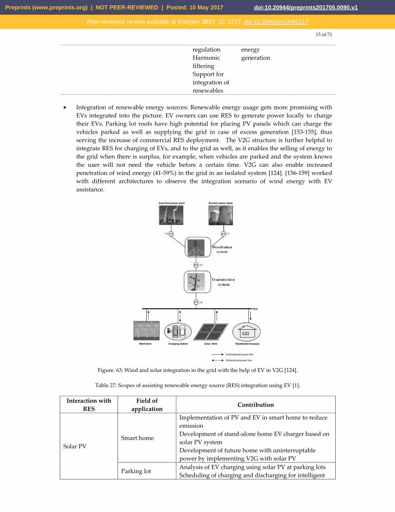
15 of 71
regulation Harmonic filtering Support for integration of renewables
energy generation
• Integration of renewable energy sources: Renewable energy usage gets more promising with
EVs integrated into the picture. EV owners can use RES to generate power locally to charge their EVs. Parking lot roofs have high potential for placing PV panels which can charge the vehicles parked as well as supplying the grid in case of excess generation [153-155], thus serving the increase of commercial RES deployment. The V2G structure is further helpful to integrate RES for charging of EVs, and to the grid as well, as it enables the selling of energy to the grid when there is surplus, for example, when vehicles are parked and the system knows the user will not need the vehicle before a certain time. V2G can also enable increased penetration of wind energy (41-59%) in the grid in an isolated system [124]. [156-159] worked with different architectures to observe the integration scenario of wind energy with EV assistance.
Figure. 63: Wind and solar integration in the grid with the help of EV in V2G [124].
Table 27: Scopes of assisting renewable energy source (RES) integration using EV [1].
Interaction with RES
Field of application
Contribution
Solar PV Smart home
Implementation of PV and EV in smart home to reduce emission Development of stand-alone home EV charger based on solar PV system Development of future home with uninterruptable power by implementing V2G with solar PV
Parking lot Analysis of EV charging using solar PV at parking lots Scheduling of charging and discharging for intelligent
Preprints (www.preprints.org) | NOT PEER-REVIEWED | Posted: 10 May 2017 doi:10.20944/preprints201705.0090.v1
Peer-reviewed version available at Energies 2017, 10, 1217; doi:10.3390/en10081217
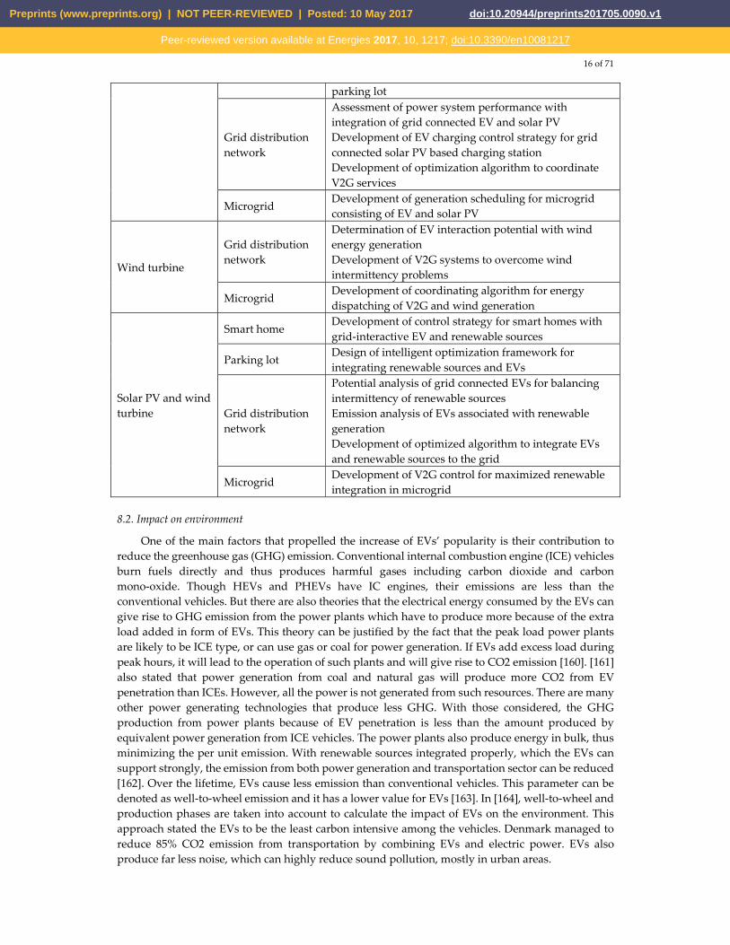
16 of 71
parking lot
Grid distribution network
Assessment of power system performance with integration of grid connected EV and solar PV Development of EV charging control strategy for grid connected solar PV based charging station Development of optimization algorithm to coordinate V2G services
Microgrid Development of generation scheduling for microgrid consisting of EV and solar PV
Wind turbine
Grid distribution network
Determination of EV interaction potential with wind energy generation Development of V2G systems to overcome wind intermittency problems
Microgrid Development of coordinating algorithm for energy dispatching of V2G and wind generation
Solar PV and wind turbine
Smart home Development of control strategy for smart homes with grid-interactive EV and renewable sources
Parking lot Design of intelligent optimization framework for integrating renewable sources and EVs
Grid distribution network
Potential analysis of grid connected EVs for balancing intermittency of renewable sources Emission analysis of EVs associated with renewable generation Development of optimized algorithm to integrate EVs and renewable sources to the grid
Microgrid Development of V2G control for maximized renewable integration in microgrid
8.2. Impact on environment
One of the main factors that propelled the increase of EVs’ popularity is their contribution to reduce the greenhouse gas (GHG) emission. Conventional internal combustion engine (ICE) vehicles burn fuels directly and thus produces harmful gases including carbon dioxide and carbon mono-oxide. Though HEVs and PHEVs have IC engines, their emissions are less than the conventional vehicles. But there are also theories that the electrical energy consumed by the EVs can give rise to GHG emission from the power plants which have to produce more because of the extra load added in form of EVs. This theory can be justified by the fact that the peak load power plants are likely to be ICE type, or can use gas or coal for power generation. If EVs add excess load during peak hours, it will lead to the operation of such plants and will give rise to CO2 emission [160]. [161] also stated that power generation from coal and natural gas will produce more CO2 from EV penetration than ICEs. However, all the power is not generated from such resources. There are many other power generating technologies that produce less GHG. With those considered, the GHG production from power plants because of EV penetration is less than the amount produced by equivalent power generation from ICE vehicles. The power plants also produce energy in bulk, thus minimizing the per unit emission. With renewable sources integrated properly, which the EVs can support strongly, the emission from both power generation and transportation sector can be reduced [162]. Over the lifetime, EVs cause less emission than conventional vehicles. This parameter can be denoted as well-to-wheel emission and it has a lower value for EVs [163]. In [164], well-to-wheel and production phases are taken into account to calculate the impact of EVs on the environment. This approach stated the EVs to be the least carbon intensive among the vehicles. Denmark managed to reduce 85% CO2 emission from transportation by combining EVs and electric power. EVs also produce far less noise, which can highly reduce sound pollution, mostly in urban areas.
Preprints (www.preprints.org) | NOT PEER-REVIEWED | Posted: 10 May 2017 doi:10.20944/preprints201705.0090.v1
Peer-reviewed version available at Energies 2017, 10, 1217; doi:10.3390/en10081217
17 of 71
The recycling of the batteries raise serious concerns though, as there are few organizations capable of recycling the lithium-ion batteries fully. However, like the previous nickel-metal and lead-acid ones, lithium-ion cells are not made of caustic chemicals, and their reuse can reduce ‘peak lithium’ or ‘peak oil’ demands [82].
8.3. Impact on economy
From the perspective of the EV owners, EVs provide less operating cost because of their superior efficiency [165], it can be up to 70% where ICE vehicles have efficiencies in the range of 60% to 70% [166]. The current high cost of EVs are likely to come down from mass production and better energy policies [167] which will further increase the economic gains of the owners. V2G also allows the owners to get financially benefitted from their vehicles by providing service to the grid [168]. The power service providers get benefitted from EV integration mainly by implementing of coordinated charging and V2G. It allows them to adopt better peak shaving strategies as well as integration of renewable sources. EV fleets can lead to $200 to $300 savings in cost per vehicle per year [169,170].
8.4. Impacts on motorsport
Hybrid technologies are not used extensively in motorsport to enhance the performance of the vehicles. Electric vehicles now have their own formula racing series named ‘Formula E’ [171] which started in Beijing on September 2014. Autonomous EVs are also being planned to take part in a segment of this series called ‘Roborace’.
9. Barriers to EV adoption
Although electric vehicles offer a lot of promises, they are still not widely adopted, and the reasons behind that are quite serious as well.
9.1. Technological problems
The main obstacles that frustrated EVs’ domination are the drawbacks of the related technology. Batteries are the main area of concern as their contribution to the weight of the car is significant. Range and charging period also depend on the battery. These factors, along with a few others, are demonstrated below:
9.1.1. Limited range
EVs are held back by the capacity of their batteries [2]. They have a certain amount of energy stored there, and can travel a distance that the stored energy allows. The range also depends on the speed of the vehicle, driving style, cargo the vehicle is carrying, the terrain it is being driven on, and the energy consuming services running in the car, for example air conditioning. This causes ‘range anxiety’ among the users [82], which indicates the concern about finding a charging station before the battery drains out. People are found to be willing to spend up to $75 extra for an extra range of one mile [172]. Though even the current BEVs are capable of traversing equivalent or more distance than a conventional vehicle can travel with a full tank (Tesla Model S 100D has a range of almost 564 kilometers on 19´´ wheels when the temperature is 70 C and the air conditioning is off [22], the Chevrolet Bolt’s range is 238 miles or 383 kilometers [173]), range anxiety remains a major obstacle for EVs to overcome. This does not affect the use of EVs for urban areas though, as in most cases this range is enough for daily commutation inside city limits. Range extenders, which produce electricity from fuel, is also available with models like BMW i3 as an option. Vehicles with such facilities are currently being called as Extended Range Electric Vehicles (EREV).
9.1.2. Long charging period
Another major downside of EVs are the long time they need to get charged. Depending on the type of charger and battery pack, charging can take from a few minutes to hours; this truly makes
Preprints (www.preprints.org) | NOT PEER-REVIEWED | Posted: 10 May 2017 doi:10.20944/preprints201705.0090.v1
Peer-reviewed version available at Energies 2017, 10, 1217; doi:10.3390/en10081217
18 of 71
EVs incompetent against the ICE vehicles which only takes a few minutes to get refueled. M. K. Hidrue et al. found out that, to have an hour decreased from the charging time, people are willing to pay $425-$3250 [172]. A way to make the charging time faster is to increase the voltage level and employment of better chargers. Some fast charging facilities are available at present, and more are being studied. There are also the fuel cell vehicles that do not require charging like other EVs. Filling up the hydrogen tank is all that has to be done in case of these vehicles, which is as convenient as filling up a fuel tank. But FCVs need sufficient hydrogen refueling stations and a feasible way to produce the hydrogen in order to thrive.
9.1.3. Safety concerns
The concern about safety is rising mainly about the FCVs now. There are speculations that, if hydrogen escapes the tanks it is kept into, can cause serious harm, as it is highly flammable. It has no color either, making a leak hard to notice. There is also the chance of the tanks to explode in case of a collision. To counter these problems, the automakers have taken measures to ensure the integrity of the tanks, they are wrapped with carbon fibers in case of Toyota Mirai. In this car, the hydrogen handling parts are placed outside the cabin, allowing the gas to disperse easily in case of any leak, there are also arrangements to seal the tank outlet in case of high-speed collision [174].
9.2. Social problems
9.2.1. Social acceptance
The acceptance of a new and immature technology, along with its consequences, takes some time in the society as it means change of certain habits [175]. Using an EV instead of a conventional vehicle means change of driving patters, refueling habits, preparedness to use an alternative transport in case of low battery, and these are not easy to adopt.
9.2.2. Insufficient charging stations
Though public charging stations have increased a lot in number, still they are not enough. Coupled with the lengthy charging time, it acts as a major deterrent against EV penetration. All the public charging stations are not compatible with every car as well, therefore it also becomes a challenge to find a proper charging point when it is required to replete the battery. There is also the risk of getting a fully occupied charging station with no room for another car. But, the manufacturers are working on to mitigate this problem. Tesla and Nissan have been expanding their own charging networks, as it, in turn means they can sell more of their EVs. Hydrogen refueling stations are not abundant yet as well. It is necessary as well to increase the adoption of FCVs. In [176], placement strategy of hydrogen refueling stations in California is discussed. It stated that a total of sixty-eight such stations will be sufficient to provide service to FCVs in the area. To get the better out of the remaining stations, there are different trip planning applications, both web based and manufacturer provided, which helps to obtain a route so that there are enough charging facilities to reach the destination.
Preprints (www.preprints.org) | NOT PEER-REVIEWED | Posted: 10 May 2017 doi:10.20944/preprints201705.0090.v1
Peer-reviewed version available at Energies 2017, 10, 1217; doi:10.3390/en10081217
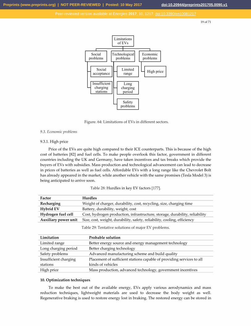
19 of 71
Figure. 64: Limitations of EVs in different sectors.
9.3. Economic problems
9.3.1. High price
Price of the EVs are quite high compared to their ICE counterparts. This is because of the high cost of batteries [82] and fuel cells. To make people overlook this factor, government in different countries including the UK and Germany, have taken incentives and tax breaks which provide the buyers of EVs with subsidies. Mass production and technological advancement can lead to decrease in prices of batteries as well as fuel cells. Affordable EVs with a long range like the Chevrolet Bolt has already appeared in the market, while another vehicle with the same promises (Tesla Model 3) is being anticipated to arrive soon.
Table 28: Hurdles in key EV factors [177].
Factor Hurdles Recharging Weight of charger, durability, cost, recycling, size, charging time Hybrid EV Battery, durability, weight, cost Hydrogen fuel cell Cost, hydrogen production, infrastructure, storage, durability, reliability Auxiliary power unit Size, cost, weight, durability, safety, reliability, cooling, efficiency
Table 29: Tentative solutions of major EV problems.
Limitation Probable solutionLimited range Better energy source and energy management technology Long charging period Better charging technology Safety problems Advanced manufacturing scheme and build quality Insufficient charging stations
Placement of sufficient stations capable of providing services to all kinds of vehicles
High price Mass production, advanced technology, government incentives
10. Optimization techniques
To make the best out of the available energy, EVs apply various aerodynamics and mass reduction techniques, lightweight materials are used to decrease the body weight as well. Regenerative braking is used to restore energy lost in braking. The restored energy can be stored in
Limitations of EVs
Social problems
Social acceptance
Insufficient charging stations
Technological problems
Limited range
Long charging period
Safety problems
Economic problems
High price
Preprints (www.preprints.org) | NOT PEER-REVIEWED | Posted: 10 May 2017 doi:10.20944/preprints201705.0090.v1
Peer-reviewed version available at Energies 2017, 10, 1217; doi:10.3390/en10081217
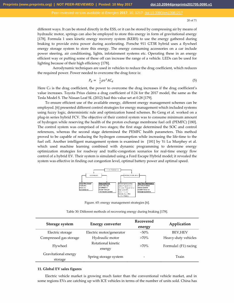
20 of 71
different ways. It can be stored directly in the ESS, or it can be stored by compressing air by means of hydraulic motor, springs can also be employed to store this energy in form of gravitational energy [178]. Formula 1 uses kinetic energy recovery system (KERS) to use the energy gathered during braking to provide extra power during accelerating. Porsche 911 GT3R hybrid uses a flywheel energy storage system to store this energy. The energy consuming accessories on a car include power steering, air conditioning, lights, infotainment systems etc. Operating these in an energy efficient way or putting some of these off can increase the range of a vehicle. LEDs can be used for lighting because of their high efficiency [178].
Aerodynamic techniques are used in vehicles to reduce the drag coefficient, which reduces the required power. Power needed to overcome the drag force is: = (5)
Here Cd is the drag coefficient, the power to overcome the drag increases if the drag coefficient’s value increases. Toyota Prius claims a drag coefficient of 0.24 for the 2017 model, the same as the Tesla Model S. The Nissan Leaf SL (2012) had this value set at 0.28 [179].
To ensure efficient use of the available energy, different energy management schemes can be employed. [6] presented different control strategies for energy management which included systems using fuzzy logic, deterministic rule and optimization based schemes. Bo Geng et al. worked on a plug-in series hybrid FCV. The objective of their control system was to consume minimum amount of hydrogen while reserving the health of the proton exchange membrane fuel cell (PEMFC) [180]. The control system was comprised of two stages; the first stage determined the SOC and control references, whereas the second stage determined the PEMFC health parameters. This method proved to be capable of reducing the hydrogen consumption while increasing the life-time to the fuel cell. Another intelligent management system is examined in [181] by Yi Lu Murphey et al. which used machine learning combined with dynamic programming to determine energy optimization strategies for roadway and traffic-congestion scenarios for real-time energy flow control of a hybrid EV. Their system is simulated using a Ford Escape Hybrid model; it revealed the system was effective in finding out congestion level, optimal battery power and optimal speed.
Figure. 65: energy management strategies [6].
Table 30: Different methods of recovering energy during braking [178].
Storage system Energy converter Recovered
energyApplication
Electric storage Electric motor/generator ~50% BEV,HEV Compressed gas storage Hydraulic motor >70% Heavy-duty vehicles
Flywheel Rotational kinetic
energy >70% Formula1 (F1) racing
Gravitational energy storage
Spring storage system - Train
11. Global EV sales figures
Electric vehicle market is growing much faster than the conventional vehicle market, and in some regions EVs are catching up with ICE vehicles in terms of the number of units sold. China has
Preprints (www.preprints.org) | NOT PEER-REVIEWED | Posted: 10 May 2017 doi:10.20944/preprints201705.0090.v1
Peer-reviewed version available at Energies 2017, 10, 1217; doi:10.3390/en10081217
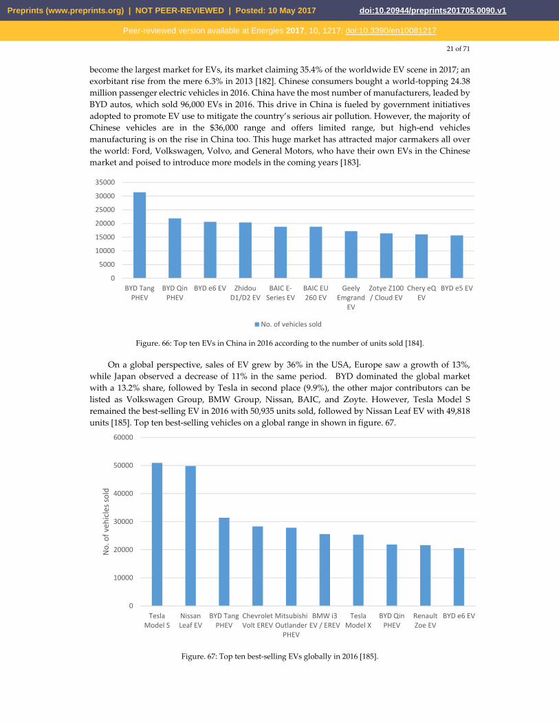
21 of 71
become the largest market for EVs, its market claiming 35.4% of the worldwide EV scene in 2017; an exorbitant rise from the mere 6.3% in 2013 [182]. Chinese consumers bought a world-topping 24.38 million passenger electric vehicles in 2016. China have the most number of manufacturers, leaded by BYD autos, which sold 96,000 EVs in 2016. This drive in China is fueled by government initiatives adopted to promote EV use to mitigate the country’s serious air pollution. However, the majority of Chinese vehicles are in the $36,000 range and offers limited range, but high-end vehicles manufacturing is on the rise in China too. This huge market has attracted major carmakers all over the world: Ford, Volkswagen, Volvo, and General Motors, who have their own EVs in the Chinese market and poised to introduce more models in the coming years [183].
Figure. 66: Top ten EVs in China in 2016 according to the number of units sold [184].
On a global perspective, sales of EV grew by 36% in the USA, Europe saw a growth of 13%, while Japan observed a decrease of 11% in the same period. BYD dominated the global market with a 13.2% share, followed by Tesla in second place (9.9%), the other major contributors can be listed as Volkswagen Group, BMW Group, Nissan, BAIC, and Zoyte. However, Tesla Model S remained the best-selling EV in 2016 with 50,935 units sold, followed by Nissan Leaf EV with 49,818 units [185]. Top ten best-selling vehicles on a global range in shown in figure. 67.
Figure. 67: Top ten best-selling EVs globally in 2016 [185].
0
5000
10000
15000
20000
25000
30000
35000
BYD TangPHEV
BYD QinPHEV
BYD e6 EV ZhidouD1/D2 EV
BAIC E-Series EV
BAIC EU260 EV
GeelyEmgrand
EV
Zotye Z100/ Cloud EV
Chery eQEV
BYD e5 EV
No. of vehicles sold
0
10000
20000
30000
40000
50000
60000
TeslaModel S
NissanLeaf EV
BYD TangPHEV
ChevroletVolt EREV
MitsubishiOutlander
PHEV
BMW i3EV / EREV
TeslaModel X
BYD QinPHEV
RenaultZoe EV
BYD e6 EV
No.
of v
ehic
les s
old
Preprints (www.preprints.org) | NOT PEER-REVIEWED | Posted: 10 May 2017 doi:10.20944/preprints201705.0090.v1
Peer-reviewed version available at Energies 2017, 10, 1217; doi:10.3390/en10081217
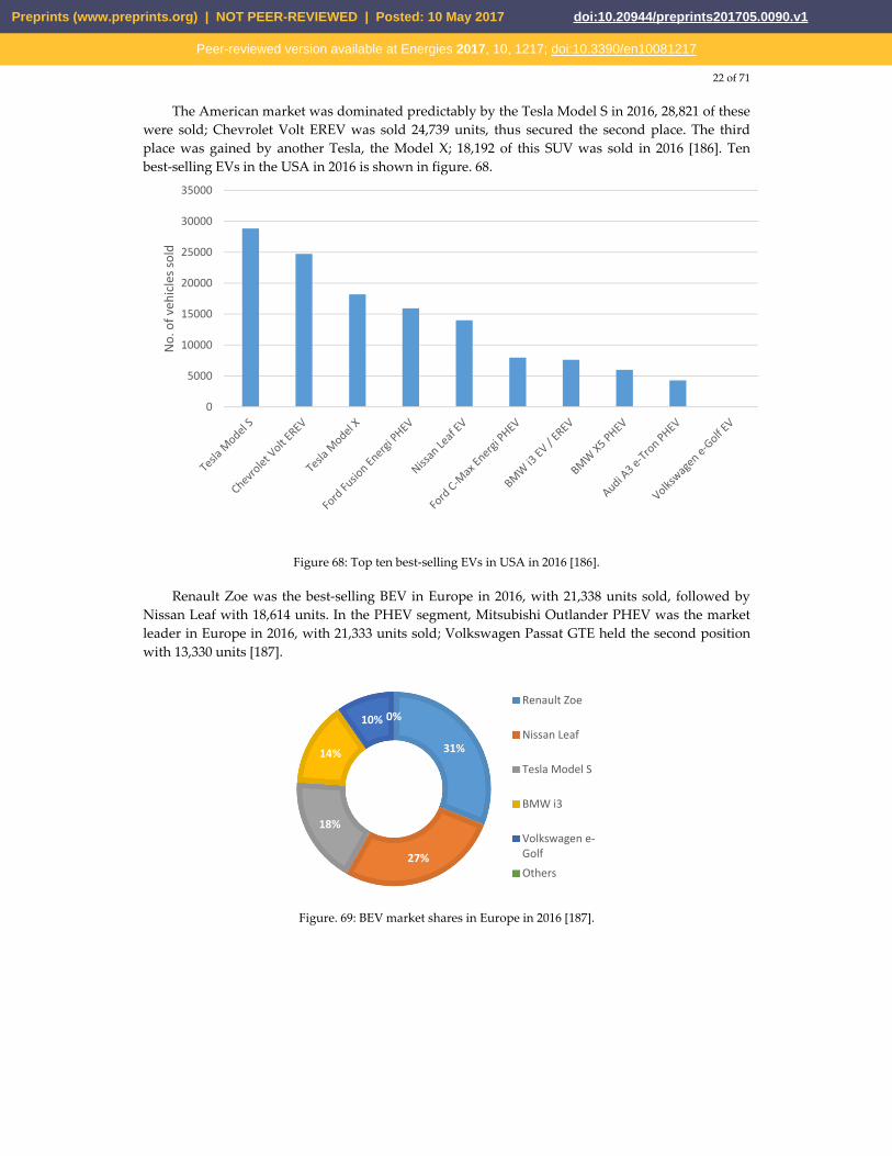
22 of 71
The American market was dominated predictably by the Tesla Model S in 2016, 28,821 of these were sold; Chevrolet Volt EREV was sold 24,739 units, thus secured the second place. The third place was gained by another Tesla, the Model X; 18,192 of this SUV was sold in 2016 [186]. Ten best-selling EVs in the USA in 2016 is shown in figure. 68.
Figure 68: Top ten best-selling EVs in USA in 2016 [186].
Renault Zoe was the best-selling BEV in Europe in 2016, with 21,338 units sold, followed by Nissan Leaf with 18,614 units. In the PHEV segment, Mitsubishi Outlander PHEV was the market leader in Europe in 2016, with 21,333 units sold; Volkswagen Passat GTE held the second position with 13,330 units [187].
Figure. 69: BEV market shares in Europe in 2016 [187].
0
5000
10000
15000
20000
25000
30000
35000
No.
of v
ehic
les s
old
31%
27%
18%
14%
10% 0%Renault Zoe
Nissan Leaf
Tesla Model S
BMW i3
Volkswagen e-GolfOthers
Preprints (www.preprints.org) | NOT PEER-REVIEWED | Posted: 10 May 2017 doi:10.20944/preprints201705.0090.v1
Peer-reviewed version available at Energies 2017, 10, 1217; doi:10.3390/en10081217

23 of 71
Figure. 70: PHEV market shares in Europe in 2016 [187].
12. Trends and future developments
The adoption of EVs has opened doors for new possibilities and ways to improve both the vehicles and the systems associated with it, the power system, for example. EVs are being considered as the future of vehicles, whereas the smart grid appears to be the grid of the future. V2G is the link between these two technologies and both get benefitted from it. With V2G comes other essential systems required for a sustainable EV scenario – charge scheduling, VPP, smart metering etc. The existing charging technologies has to improve a lot to make EVs widely accepted. The charging time has to be decreased extensively for making EVs more flexible. At the same time, chargers and EVSEs have to able to communicate with the grid for facilitating V2G, smart metering, and if needed, bidirectional charging [21]. Better batteries are a must to take the EV technology further. There is need of batteries that uses non-toxic materials and have higher power density, less cost and weight, more capacity, and needs less time to get recharged. Though are technologies better than the Li-ion is discovered already, they are not being pursued industrially because of the huge cost associated with creating a working version. And besides, Li-ion technology has potential to be improved a lot more. Li-air battery can be a good option to increase the range of EVs [21]. EVs are likely to move away from using permanent magnet motors which use rare-earth materials. The motors of choice can be induction motor, synchronous reluctance motor, and switched reluctance motor [21]. Tesla is using induction motor in its models at present. Motors with internal permanent magnet may stay in use [21]. Wireless power transfer systems are likely to replace the current cabled charging system. Concepts revealed by major automakers adopted this feature to highlight their usefulness and convenience. The Rolls-Royce 103EX and the Vision Mercedes-Maybach 6 can be taken as example for that. Electric roads for wireless charging of vehicles may appear as well. Though it is not still viable, the future may contradict. Recent works in this sector includes the work of Electrode, an Israeli startup, which claims to be able to achieve this feat in an economic way. Vehicles that follow a designated route along the highway, like trucks, can get their power from overhead lines like trains or trams. It will allow them to gather energy as long as their route resides with the power lines, then carry on with energy from on-board sources. Such a system has been tested by Siemens using diesel-hybrid trucks from Scania on a highway in Sweden [188]. New ways of recovering energy from the vehicle may appear. Goodyear has demonstrated a tire that can harvest energy from the heat generated there using thermo-piezoelectric material. There are also chances of solar-powered vehicles. Until now, these have not appeared useful as installed solar cells managed to convert up to 20% of the input power only [71].
32%
20%17%
16%
15% 0%
Mitsubishi Outlander PHEVVolkswagen Passat GTEVolkswagen Golf GTEMercedes C350eVolvo XC90 PHEVOthers
Preprints (www.preprints.org) | NOT PEER-REVIEWED | Posted: 10 May 2017 doi:10.20944/preprints201705.0090.v1
Peer-reviewed version available at Energies 2017, 10, 1217; doi:10.3390/en10081217
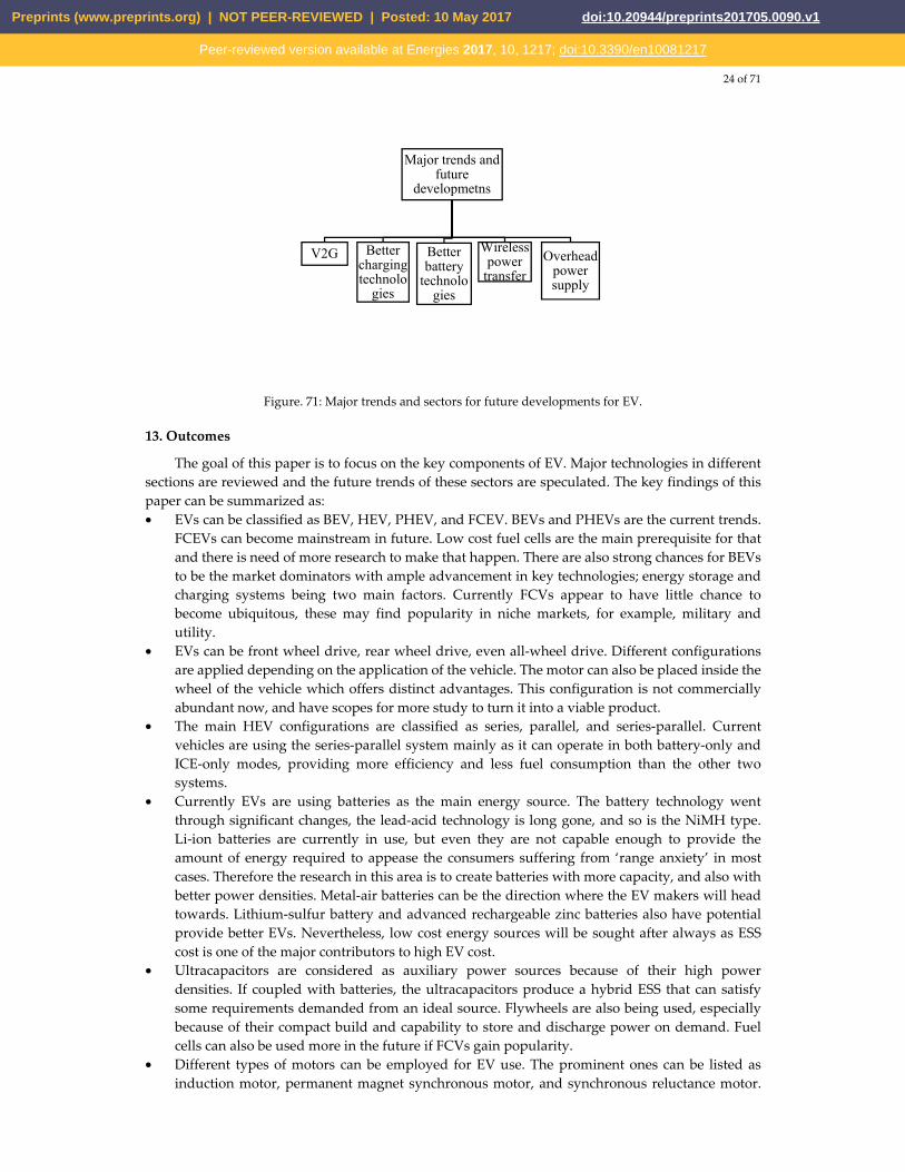
24 of 71
Figure. 71: Major trends and sectors for future developments for EV.
13. Outcomes
The goal of this paper is to focus on the key components of EV. Major technologies in different sections are reviewed and the future trends of these sectors are speculated. The key findings of this paper can be summarized as: • EVs can be classified as BEV, HEV, PHEV, and FCEV. BEVs and PHEVs are the current trends.
FCEVs can become mainstream in future. Low cost fuel cells are the main prerequisite for that and there is need of more research to make that happen. There are also strong chances for BEVs to be the market dominators with ample advancement in key technologies; energy storage and charging systems being two main factors. Currently FCVs appear to have little chance to become ubiquitous, these may find popularity in niche markets, for example, military and utility.
• EVs can be front wheel drive, rear wheel drive, even all-wheel drive. Different configurations are applied depending on the application of the vehicle. The motor can also be placed inside the wheel of the vehicle which offers distinct advantages. This configuration is not commercially abundant now, and have scopes for more study to turn it into a viable product.
• The main HEV configurations are classified as series, parallel, and series-parallel. Current vehicles are using the series-parallel system mainly as it can operate in both battery-only and ICE-only modes, providing more efficiency and less fuel consumption than the other two systems.
• Currently EVs are using batteries as the main energy source. The battery technology went through significant changes, the lead-acid technology is long gone, and so is the NiMH type. Li-ion batteries are currently in use, but even they are not capable enough to provide the amount of energy required to appease the consumers suffering from ‘range anxiety’ in most cases. Therefore the research in this area is to create batteries with more capacity, and also with better power densities. Metal-air batteries can be the direction where the EV makers will head towards. Lithium-sulfur battery and advanced rechargeable zinc batteries also have potential provide better EVs. Nevertheless, low cost energy sources will be sought after always as ESS cost is one of the major contributors to high EV cost.
• Ultracapacitors are considered as auxiliary power sources because of their high power densities. If coupled with batteries, the ultracapacitors produce a hybrid ESS that can satisfy some requirements demanded from an ideal source. Flywheels are also being used, especially because of their compact build and capability to store and discharge power on demand. Fuel cells can also be used more in the future if FCVs gain popularity.
• Different types of motors can be employed for EV use. The prominent ones can be listed as induction motor, permanent magnet synchronous motor, and synchronous reluctance motor.
Major trends and future
developmetns
V2G Better charging technolo
gies
Better battery
technologies
Wireless power
transfer
Overhead power supply
Preprints (www.preprints.org) | NOT PEER-REVIEWED | Posted: 10 May 2017 doi:10.20944/preprints201705.0090.v1
Peer-reviewed version available at Energies 2017, 10, 1217; doi:10.3390/en10081217
25 of 71
Induction motors are being extensively these days, they can also dominate in future because of their independence on rare-earth material permanent magnets.
• EVs can be charged with AC or DC supply. There are different voltage levels and they are designated accordingly. Higher voltage levels provide faster charging. DC supplies negate the need of rectification from AC, which reduces delay and loss. However, with increased voltage level, the pressure on the grid increases and can give rise to harmonics as well as voltage imbalance in an unsupervised system. Therefore, there is ample chances of research in the field of mitigating the problems associated with high-voltage charging.
• Two charger configurations are mainly available now: CCS and CHAdeMO. These two systems are not compatible with each other and each has a number of automakers supporting them. Tesla also brought their own ‘supercharger’ system, which provides a faster charging facility. It is not possible to determine now which one of these will prevail, or if both will co-exist, technical study is needed to find out the most useful one of these configurations or ways to make them compatible with each other.
• Whatever the charging system is, the charging time is still very long. It is a major disadvantage that is thwarting the growth of the EV market. Extensive research is needed in this sector to provide better technologies that can provide much faster charging and can be compatible with the small time required to refill an ICE vehicle. Wireless charging is also something in need of research. With all the conveniences it promises, it is still not in a viable form to commercialize.
• EV impacts the environment, power system, and economy alongside the transportation sector. It shows promises to reduce the GHG emission as well as efficient and economical transport solutions. At the same time, it can cause serious problems in the power system including voltage instability, harmonics, and voltage sag. But these shortcomings may be short-lived by the employment smart grid technologies. There is prospects of research in the areas of V2G, smart metering, integration of RES, and system stability associated with EV penetration.
• EVs employ different techniques to reduce energy loss and increase efficiency. Reducing the drag coefficient, weight reduction, regenerative braking, and intelligent energy management being some of these optimization techniques. Further research directions can be better aerodynamic body designs, new materials with less weight and desired strength, ways to generate and restore the energy lost.
14. Conclusion
EVs have great potential of becoming the future of transport while saving this planet from imminent calamities caused by global warming. They are a viable alternative to the conventional vehicles depending directly on the diminishing fossil fuel reserves. EV types, configurations, energy sources, motors, power conversion and charging technologies for EVs have been discussed in detail in this paper. The key technologies of each section have been reviewed and their characteristics have been presented. The impacts the EVs cause in different sectors have been discussed as well, along with the huge possibilities they hold to promote a better and greener energy system by collaborating with smart grid and facilitating the integration of renewable sources. Limitations of current EVs have been listed along with probable solutions to overcome the shortcomings. The current optimization techniques have also been included. Finally, trends and ways of future developments have been assessed followed by the outcomes of this paper to summarize the whole text, providing a clear picture of this sector and the areas in need of further research. Acknowledgments: No funding sources for the proposed investigation research and its results decimation. Author Contributions: All authors involved and contributed for framing the manuscript for its current decimation format. All authors significant contributed includes insight survey on the literatures and state of art in literature survey for writing the complete scenario of the review paper. Conflicts of Interest: Declare conflicts of interest or state “The authors declare no conflict of interest."
Preprints (www.preprints.org) | NOT PEER-REVIEWED | Posted: 10 May 2017 doi:10.20944/preprints201705.0090.v1
Peer-reviewed version available at Energies 2017, 10, 1217; doi:10.3390/en10081217

26 of 71
References
1. Yong, Jia Ying, et al. "A review on the state-of-the-art technologies of electric vehicle, its impacts and prospects." Renewable and Sustainable Energy Reviews 49 (2015): 365-385.
2. C. C. Chan, "The state of the art of electric and hybrid vehicles," in Proceedings of the IEEE, vol. 90, no. 2, pp. 247-275, Feb 2002.
3. Grunditz, Emma Arfa, and Torbjörn Thiringer. "Performance Analysis of Current BEVs Based on a Comprehensive Review of Specifications." IEEE Transactions on Transportation Electrification 2.3 (2016): 270-289.
4. SAE Electric Vehicle and Plug-in Hybrid Electric Vehicle Conductive Charge Coupler, SAE Standard J1772, Jan. 2010.
5. Yilmaz, Murat, and Philip T. Krein. "Review of battery charger topologies, charging power levels, and infrastructure for plug-in electric and hybrid vehicles." IEEE Transactions on Power Electronics 28.5 (2013): 2151-2169.
6. Bayindir, Kamil Çağatay, Mehmet Ali Gözüküçük, and Ahmet Teke. "A comprehensive overview of hybrid electric vehicle: Powertrain configurations, powertrain control techniques and electronic control units." Energy Conversion and Management 52.2 (2011): 1305-1313.
7. M. Marchesoni and C. Vacca, “New DC–DC converter for energy storage system interfacing in fuel cell hybrid electric vehicles,” IEEE Trans. Power Electron., vol. 22, no. 1, pp. 301–308, Jan. 2007.
8. E. Schaltz, A. Khaligh, and P. O. Resmussen, “Influence of battery/ultracapacitor energy-storage sizing on battery lifetime in a fuel cell hybrid electric vehicle,” IEEE Trans. Veh. Technol., vol. 58, no. 8, pp. 3882–3891, Oct. 2009.
9. B. Kramer, S. Chakraborty, and B. Kroposki, “A review of plug-in vehicles and vehicle-to-grid capability,” in Proc. 34th IEEE Ind. Electron. Annu. Conf., Nov. 2008, pp. 2278–2283.
10. S. S. Williamson, “Electric drive train efficiency analysis based on varied energy storage system usage for plug-in hybrid electric vehicle applications,” in Proc. IEEE Power Electron. Spec. Conf., Jun. 2007, pp. 1515–1520.
11. S. G. Wirasingha, N. Schofield, and A. Emadi, “Plug-in hybrid electric vehicle developments in the US: trends, barriers, and economic feasibility,” in Proc. IEEE Vehicle Power Propulsion Conf., Sep. 2008, pp. 1–8.
12. Y. Gao and M. Ehsani, “Design and control methodology of plug-in hybrid electric vehicles,” in Proc. IEEE Vehicle Power Propulsion Conf., Sep. 2008, pp. 1–6.
13. The Fuel Cell Handbook, U.S. Dept. Energy, Morgantown, WV, 2002. 14. J. F. Miller, C. E. Webster, A. F. Tummillo, and W. H. DeLuca, “Testing and evaluation of batteries for a
fuel cell powered hybrid bus,” in Proc. Energy Convers. Eng. Conf., Jul./Aug. 1997, vol. 2, pp. 894–898. 15. P. Rodatz, O. Garcia, L. Guzzella, F. Büchi, M. Bärtschi, A. Tsukada,and P. Dietrich, “Performance and
operational characteristics of a hybrid vehicle powered by fuel cells and supercapacitors,” in Proc. SAE 2003 World Cong. Exhib., Mar. 2003, vol. 112, pp. 692–703, Doc. no. 2003-01-0418.
16. P. Thounthong, S. Rael, and B. Davat, “Utilizing fuel cell and supercapacitors for automotive hybrid electrical system,” in Proc. Appl. Power Electron. Conf. Expo., 2005, vol. 1, pp. 90–96.
17. Why the Automotive Future Will Be Dominated by Fuel Cells - IEEE Spectrum. Available online: http://spectrum.ieee.org/green-tech/fuel-cells/why-the-automotive-future-will-be-dominated-by-fuel-cells (accessed on 8 May 2017).
18. R. Rose, Questions and Answers About Hydrogen and Fuel Cells (Report style), 2005, Washington, DC: U.S. Dept. Energy.
19. U.S. Climate Technology Program: Technology Options for the Near and Long Term (Report style), Aug. 2005, Washington, DC: U.S. Climate Change Technol. Program.
20. Thomas, C. E. "Fuel cell and battery electric vehicles compared."international journal of hydrogen energy 34.15 (2009): 6005-6020.
21. Rajashekara, Kaushik. "Present status and future trends in electric vehicle propulsion technologies." IEEE Journal of Emerging and Selected Topics in Power Electronics 1.1 (2013): 3-10.
22. Model S | Tesla. Available online: https://www.tesla.com/models (accessed on 8 May 2017). 23. F. Tahami, R. Kazemi and S. Farhanghi, "A novel driver assist stability system for
all-wheel-drive electric vehicles," in IEEE Transactions on Vehicular Technology, vol. 52, no. 3, pp. 683-692, May 2003.
Preprints (www.preprints.org) | NOT PEER-REVIEWED | Posted: 10 May 2017 doi:10.20944/preprints201705.0090.v1
Peer-reviewed version available at Energies 2017, 10, 1217; doi:10.3390/en10081217
27 of 71
24. M. Sato, G. Yamamoto, D. Gunji, T. Imura and H. Fujimoto, "Development of Wireless In-Wheel Motor Using Magnetic Resonance Coupling," in IEEE Transactions on Power Electronics, vol. 31, no. 7, pp. 5270-5278, July 2016.
25. Kurs A, Karalis A, Moffatt R, Joannopoulos JD, Fisher P, Soljacic M (2007) Wireless power transfer via strongly coupled magnetic resonances. Science 317(5834):83–86.
26. Imura, Takehiro, Toshiyuki Uchida, and Yoichi Hori. "Flexibility of contactless power transfer using magnetic resonance coupling to air gap and misalignment for EV." World Electric Vehicle Journal 3.1 (2009): 24-34.
27. S. Nakadachi, S. Mochizuki, S. Sakaino, Y. Kaneko, S. Abe and T. Yasuda, "Bidirectional contactless power transfer system expandable from unidirectional system," 2013 IEEE Energy Conversion Congress and Exposition, Denver, CO, 2013, pp. 3651-3657.
28. Nam, Kanghyun, Hiroshi Fujimoto, and Yoichi Hori. "Lateral stability control of in-wheel-motor-driven electric vehicles based on sideslip angle estimation using lateral tire force sensors." IEEE Transactions on Vehicular Technology61.5 (2012): 1972-1985.
29. Yimin Gao, M. Ehsani and J. M. Miller, "Hybrid Electric Vehicle: Overview and State of the Art," Proceedings of the IEEE International Symposium on Industrial Electronics, 2005. ISIE 2005., Dubrovnik, Croatia, 2005, pp. 307-316.
30. HILTech Developments Limited (application notes) vehicle hybrid powertrain architectures; 2006.
31. H. Kim and D. Kum, "Comprehensive Design Methodology of Input- and Output-Split Hybrid Electric Vehicles: In Search of Optimal Configuration," in IEEE/ASME Transactions on Mechatronics, vol. 21, no. 6, pp. 2912-2923, Dec. 2016.
32. Miller, John M. "Hybrid electric vehicle propulsion system architectures of the e-CVT type." IEEE Transactions on Power Electronics 21.3 (2006): 756-767.
33. H. Kim and D. Kum, "Comprehensive Design Methodology of Input- and Output-Split Hybrid Electric Vehicles: In Search of Optimal Configuration," in IEEE/ASME Transactions on Mechatronics, vol. 21, no. 6, pp. 2912-2923, Dec. 2016.
34. D. Kim, S. Hwang and H. Kim, "Vehicle Stability Enhancement of Four-Wheel-Drive Hybrid Electric Vehicle Using Rear Motor Control," in IEEE Transactions on Vehicular Technology, vol. 57, no. 2, pp. 727-735, March 2008.
35. Li, Yong, Jie Yang, and Jian Song. "Nano energy system model and nanoscale effect of graphene battery in renewable energy electric vehicle."Renewable and Sustainable Energy Reviews 69 (2017): 652-663.
36. Khaligh, Alireza, and Zhihao Li. "Battery, ultracapacitor, fuel cell, and hybrid energy storage systems for electric, hybrid electric, fuel cell, and plug-in hybrid electric vehicles: State of the art." IEEE transactions on Vehicular Technology 59.6 (2010): 2806-2814.
37. J. B. Olson and E. D. Sexton, “Operation of lead–acid batteries for HEV applications,” in Proc. 15th Battery Conf. Appl. Adv., Jan. 2000, pp. 205–210.
38. D. B. Edwards and C. Kinney, “Advanced lead acid battery designs for hybrid electric vehicles,” in Proc. 16th Battery Conf. Appl. Adv., Jan. 2001, pp. 207–212.
39. A. Cooper and P. Moseley, “Progress in the development of lead–acid batteries for hybrid electric vehicles,” in Proc. IEEE Vehicle Power Propulsion Conf., Sep. 2006, pp. 1–6.
40. Fetcenko, M. A., et al. "Recent advances in NiMH battery technology."Journal of Power Sources 165.2 (2007): 544-551.
41. H. Li, C. Liao, and L. Wang, “Research on state-of-charge estimation of battery pack used on hybrid electric vehicle,” in Proc. Asia-Pacific Power Energy Eng. Conf., Mar. 2009, pp. 1–4.
42. S. G. Chalk and J. F. Miller, “Key challenges and recent progress in batteries, fuel cells, and hydrogen storage for clean energy systems,” J. Power Sources, vol. 159, no. 1, pp. 73–80, Sep. 2006.
43. R. C. Balch, A. Burke, and A. A. Frank, “The affect of battery pack technology and size choices on hybrid electric vehicle performance and fuel economy,” in Proc. 16th IEEE Annu. Battery Conf. Appl. Adv., Jan. 2001, pp. 31–36.
Preprints (www.preprints.org) | NOT PEER-REVIEWED | Posted: 10 May 2017 doi:10.20944/preprints201705.0090.v1
Peer-reviewed version available at Energies 2017, 10, 1217; doi:10.3390/en10081217
28 of 71
44. J. C. Viera, M. Gonzalez, J. C. Anton, J. C. Campo, F. J. Ferrero, and M. Valledor, “NiMH vs NiCd batteries under high charging rates,” in Proc. 28th Annu. Telecommun. Energy Conf., Sep. 2006, pp. 1–6.
45. Y. Gao and M. Ehsani, “Investigation of battery technologies for the army’s hybrid vehicle application,” in Proc. 56th IEEE Veh. Technol. Conf., Sep. 2002, pp. 1505–1509.
46. C Pilot, “The worldwide rechargeable battery market 2003-2004,” in Proc. Sixth Int. Battery Fair, Beijing, China, Apr. 2004.
47. Williamson, Sheldon S., Akshay K. Rathore, and Fariborz Musavi. "Industrial electronics for electric transportation: Current state-of-the-art and future challenges." IEEE Transactions on Industrial Electronics 62.5 (2015): 3021-3032.
48. P. A. Cassani and S. S. Williamson, “Feasibility analysis of a novel cell equalizer topology for plug-in hybrid electric vehicle energy-storage systems,” IEEE Trans. on Vehicular Technology, vol. 58, no. 8, pp. 3938-3946, Oct. 2009.
49. A. C. Baughman and M. Ferdowsi, “Double-tiered switched-capacitor battery charge equalization technique,” IEEE Trans. on Ind. Electron., vol. 55, no. 6, pp. 2277-2285, June 2008.
50. K. Nishijima, H. Sakamoto, and K. Harada, “A PWM controlled simple and high performance battery balancing system,” in Proc. IEEE Power Electronics Specialists Conf., June 2000, Galway, Ireland, vol. 1, pp. 517-520.
51. P. A. Cassani and S. S. Williamson, "Design, testing, and validation of a simplified control scheme for a novel plug-in hybrid electric vehicle battery cell equalizer," IEEE Trans. on Ind. Electron., vol. 57, no. 12, pp. 3956-3962, Dec. 2010.
52. Y. S. Lee and M. W. Cheng, “Intelligent control battery equalization for series connected lithium-ion battery strings,” IEEE Trans. on Ind. Electron., vol. 52, no. 5, pp. 1297-1307, Oct. 2005.
53. Y. S. Lee, M. W. Cheng, S. C. Yang, and C. L. Hsu, “Individual cell equalization for series connected lithium-ion batteries,” IEICE Trans. on Communication, vol. E89-B, no. 9, pp. 2596-2607, Sept. 2006.
54. 2017 Nissan LEAF® Electric Car Specs. Available online: https://www.nissanusa.com/electric-cars/leaf/versions-specs/ (accessed on 8 May 2017).
55. Model S Specifications | Tesla. Available online: https://www.tesla.com/support/model-s-specifications (accessed on 8 May 2017).
56. Why We Still Don’t Have Better Batteries - MIT Technology Review. Available online: https://www.technologyreview.com/s/602245/why-we-still-dont-have-better-batteries/ (accessed on 8 May 2017).
57. P. F. Ribeiro, B. K. Johnson, M. L. Crow, A. Arsoy, and Y. Liu, “Energy storage systems for advanced power applications,” in Proc. IEEE, Dec. 2001, vol. 89, no. 12, pp. 1744–1756.
58. T. Bartley, “Ultracapacitors and batteries for energy storage in heavy-duty hybrid-electric vehicles,” presented at the 22nd Int. Battery Seminar Exh., Mar. 2005.
59. Gigaom | How ultracapacitors work (and why they fall short). Available online: https://gigaom.com/2011/07/12/how-ultracapacitors-work-and-why-they-fall-short/ (accessed on 8 May 2017).
60. Singh, Anupama, and P. B. Karandikar. "A broad review on desulfation of lead-acid battery for electric hybrid vehicle." Microsystem Technologies(2016): 1-11.
61. Chiu, Huang-Jen, and Li-Wei Lin. "A bidirectional DC-DC converter for fuel cell electric vehicle driving system." IEEE Trans. Power Electron 21.4 (2006): 950-958.
62. Mahlia, T. M. I., et al. "A review of available methods and development on energy storage; technology update." Renewable and Sustainable Energy Reviews 33 (2014): 532-545.
63. Bolund B, Bernhoff H, Leijon M. Flywheel energy and power storage systems. Renew Sustain Energy Rev 2007;11:235–58.
64. Luo, X., Wang, J., Dooner, M. and Clarke, J., 2015. Overview of current development in electrical energy storage technologies and the application potential in power system operation. Applied Energy, 137, pp.511-536.
65. C. C. Chan and K. T. Chau, “An overview of power electronics in electric vehicles,” IEEE Trans. Ind. Electron., vol. 44, pp. 3–13, Feb. 1997.
Preprints (www.preprints.org) | NOT PEER-REVIEWED | Posted: 10 May 2017 doi:10.20944/preprints201705.0090.v1
Peer-reviewed version available at Energies 2017, 10, 1217; doi:10.3390/en10081217
29 of 71
66. C. C. Chan, K. T. Chau, J. Z. Jiang, W. Xia, M. Zhu, and R. Zhang, “Novel permanent magnet motor drives for electric vehicles,” IEEE Trans. Ind. Electron., vol. 43, pp. 331–339, Apr. 1996.
67. C. C. Chan, K. T. Chau, and J. M. Yao, “Soft-switching vector control for resonant snubber based inverters,” in Proc. IEEE Int. Conf. Industrial Electronics, Nov. 1997, pp. 605–610.
68. C. C. Chan, J. Z. Jiang, G. H. Chen, and K. T. Chau, “Computer simulation and analysis of a new polyphase multipole motor drive,” IEEE Trans. Ind. Electron., vol. 40, pp. 570–576, Dec. 1993.
69. C. C. Chan, J. Z. Jiang, G. H. Chen, X. Y. Wang, and K. T. Chau, “A novel polyphase multipole square-wave permanent magnet motor drive for electric vehicles,” IEEE Trans. Ind. Applicat., vol. 30, pp. 1258–1266, Sept. 1994.
70. C. C. Chan, J. Z. Jiang, W. Xia, and K. T. Chau, “Novel wide range speed control of permanent magnet brushless motor drives,” IEEE Trans. Power Electron., vol. 10, pp. 539–546, Sept. 1995.
71. Jose, C. Parag, and S. Meikandasivam. "A Review on the Trends and Developments in Hybrid Electric Vehicles." Innovative Design and Development Practices in Aerospace and Automotive Engineering. Springer Singapore, 2017. 211-229.
72. C. C. Chen and K.T.Chau, Morden Elcetric Vehicle Technology, Published by the US by Oxford University Press, Inc., New york, 2001, page, 122- 133.
73. Lulhe, Anurag M., and Tanuja N. Date. "A technology review paper for drives used in electrical vehicle (EV) & hybrid electrical vehicles (HEV)." Control, Instrumentation, Communication and Computational Technologies (ICCICCT), 2015 International Conference on. IEEE, 2015.
74. F. Magnussen, “On design and analysis of synchronous permanent magnet for field –weakening operation,” Ph.D. dissertation, Royal Institute of Tech., Sweden, 2004.
75. Model X Specifications | Tesla. Available online: https://www.tesla.com/support/model-x-specifications (accessed on 8 May 2017).
76. K. Yamada, K. Watanabe, T. Kodama, I. Matsuda, and T. Kobayashi, “An efficiency maximizing induction motor drive system for transmissionless electric vehicle,” in Proc. 13th Int. Electric Vehicle Symp., vol. II, Oct. 1996, pp. 529–536.
77. Boglietti, Aldo, et al. "A new design criteria for spindles induction motors controlled by field oriented technique." Electric Machines & Power Systems21.2 (1993): 171-182.
78. M. Abbasian, M. Moallem, and B. Fahimi, “Double-stator switched reluctance machines (DSSRM): Fundamentals and magnetic force analysis,” IEEE Trans. Energy Convers., vol. 25, no. 3, pp. 589–597, Sep. 2010.
79. Cameron, D. E., Lang, J. H., & Umans, S. D. (1992). The origin and reduction of acoustic noise in doubly salient variable-reluctance motors. IEEE Transactions on Industry Applications, 28(6), 1250-1255.
80. C. C. Chan, Q. Jiang, Y. J. Zhan, and K. T. Chau, “A high-performance switched reluctance drive for P-star EV project,” in Proc. 13th Int. Electric Vehicle Symp., vol. II, Oct. 1996, pp. 78–83.
81. Y. J. Zhan, C. C. Chan, and K. T. Chau, “A novel sliding-mode observer for indirect position sensing of switched reluctance motor drives,” IEEE Trans. Ind. Electron., vol. 46, pp. 390–397, Apr. 1999.
82. Shareef, Hussain, Md Mainul Islam, and Azah Mohamed. "A review of the stage-of-the-art charging technologies, placement methodologies, and impacts of electric vehicles." Renewable and Sustainable Energy Reviews 64 (2016): 403-420.
83. Yu, Xiang Eric, et al. "Microgrid and transportation electrification: A review."Transportation Electrification Conference and Expo (ITEC), 2012 IEEE. IEEE, 2012.
84. Musavi, Fariborz, and Wilson Eberle. "Overview of wireless power transfer technologies for electric vehicle battery charging." IET Power Electronics 7.1 (2014): 60-66.
85. Kurs, A., Karalis, A., Moffatt, R., Joannopoulos, J.D., Fisher, P., Soljacic, M.: ‘Wireless power transfer via strongly coupled magnetic resonances’, Int. Sci. J., American Association for the Advancement of Science (AAAS), 2007, 317, pp. 83–86.
86. Wu, H.H., Boys, J.T., Covic, G.A.: ‘An AC processing pickup for IPT systems’, IEEE Trans. Power Electron., 2010, 25, pp. 1275–1284.
87. Wang, C.S., Stielau, O.H., Covic, G.A.: ‘Design considerations for a contactless electric vehicle battery charger’, IEEE Trans. Ind. Electron., 2005, 52, pp. 1308–1314.
Preprints (www.preprints.org) | NOT PEER-REVIEWED | Posted: 10 May 2017 doi:10.20944/preprints201705.0090.v1
Peer-reviewed version available at Energies 2017, 10, 1217; doi:10.3390/en10081217
30 of 71
88. ‘Limits of human exposure to radiofrequency electromagnetic energy in the frequency range from 3 kHz to 300 GHz’, Health Canada, Safety Code 6 (2009).
89. ‘IEEE standard for safety levels with respect to human exposure to radio frequency electromagnetic fields, 3 kHz to 300 GHz’, IEEE Std C95.1, 1999 Edition.
90. ‘Icnirp guidelines: for limiting exposure to time-varying electric, magnetic and electromagnetic fields (up to 300 GHz)’, ICNIRP Publication – Health Phys., 1998, 74, (4), pp. 494–522.
91. ‘Radiation protection standard: maximum exposure levels to radiofrequency fields – 3 kHz to 300 GHz’, Australian Radiation Protection And Nuclear Safety Agency (ARPANSA), Radiation Protection Series Publication No. 3.
92. Chademo-ceritifed chrager list. Available online: www.chademo.com (accessed on 6 July 2015). 93. Supercharger. Available online: www.teslamotors.com (accessed on 7 July 2015). 94. SAE Standard J1772, “SAE Electric Vehicle and Plug-in Hybrid Electric Vehicle Conductive Charge
Coupler,” 2010. 95. “Standard IEC 62196 - Plugs, socket-outlets, vehicle connectors and vehicle inlets - Conductive
charging of electric vehicles,” 2014. 96. Omar C. Onar, Jonathan Kobayashi, Alireza Khaligh "A Fully Directional Universal Power
Electronic Interface for EV, HEV, and PHEV Applications" IEEE TRANSACTIONS ON POWER ELECTRONICS, VOL. 28, NO. 12, DECEMBER 2013 pp.5489-5498.
97. Bose, Bimal K. "Power electronics-a technology review." Proceedings of the IEEE 80.8 (1992): 1303-1334.
98. Kolar, Johann W., et al. "Review of three-phase PWM AC–AC converter topologies." IEEE Transactions on Industrial Electronics 58.11 (2011): 4988-5006.
99. Yaramasu, Venkata, et al. "High-power wind energy conversion systems: State-of-the-art and emerging technologies." Proceedings of the IEEE 103.5 (2015): 740-788.
100. Zhang, Zhe, et al. "A review and design of power electronics converters for fuel cell hybrid system applications." Energy Procedia 20 (2012): 301-310.
101. Kok, Dirk, Adrian Morris, and Michael Knowles. "Novel EV drive train topology—A review of the current topologies and proposal for a model for improved drivability." Power Electronics and Applications (EPE), 2013 15th European Conference on. IEEE, 2013.
102. Hegazy, Omar, Joeri Van Mierlo, and Philippe Lataire. "Analysis, control and comparison of DC/DC boost converter topologies for fuel cell hybrid electric vehicle applications." Power Electronics and Applications (EPE 2011), Proceedings of the 2011-14th European Conference on. IEEE, 2011.
103. Jinseok Hong, Heekwang Lee, Kwanghee Nam "Charging Method for the Secondary Battery in Dual-Inverter Drive Systems for Electric Vehicles" IEEE TRANSACTIONS ON POWER ELECTRONICS, VOL. 30, NO. 2, FEBRUARY 2015 pp. 909-921.
104. Sangdehi, S. Mahdi Mousavi, Saeedeh Hamidifar, and Narayan C. Kar. "A novel bidirectional DC/AC stacked matrix converter design for electrified vehicle applications." IEEE Transactions on Vehicular Technology 63.7 (2014): 3038-3050.
105. Kim, Yoon-Jae, and Jun-Young Lee. "Full-Bridge+ SRT Hybrid DC/DC Converter for a 6.6-kW EV On-Board Charger." IEEE Transactions on Vehicular Technology 65.6 (2016): 4419-4428.
106. Kimura, Shota, et al. "Downsizing Effects of Integrated Magnetic Components in High Power Density DC–DC Converters for EV and HEV Applications."IEEE Transactions on Industry Applications 52.4 (2016): 3294-3305.
107. J. C. Schroeder and F. W. Fuchs, “Detailed Characterization of Coupled Inductors in Interleaved Converters Regarding the Demand for Additional Filtering”, Proc. IEEE Energy Conver. Cong. And Expo. (ECCE), pp.759-766, 2012.
108. Imaoka, Jun, et al. "Analysis of output capacitor voltage ripple in multi-phase transformer-linked boost chopper circuit." IEEJ Journal of Industry Applications 2.5 (2013): 252-260.
109. J. Zhu, A. Pratt, “Capacitor Ripple Current in an interleaved PFC Converter”, IEEE Trans. Power Electron., vol. 24, no. 6, pp. 1506-1514, 2009.
Preprints (www.preprints.org) | NOT PEER-REVIEWED | Posted: 10 May 2017 doi:10.20944/preprints201705.0090.v1
Peer-reviewed version available at Energies 2017, 10, 1217; doi:10.3390/en10081217
31 of 71
110. C. Wang, M. Xu, F. C. Lee and B. Lu, “EMI Study for the Interleaved Multi-Channel PFC”, Proc. IEEE Power Electron. Specialists Conf. (PESC), pp. 1336-1342, 2007.
111. Michael O’Loughlin. An Interleaved PFC Preregulator for High-Power Converters [Online]. 112. L. Balogh and R. Redl, "Power-factor correction with interleaved boost converters in
continuous-inductor-current mode," in Proc. IEEE Applied Power Electronics Conf. and Expo., San Diego, CA, March 1993, pp. 168-174.
113. Y. Jang and M. M. Jovanovic, "Interleaved boost converter with intrinsic voltage-doubler characteristic for universal-line PFC front end," IEEE Trans. on Power Electronics, vol. 22, pp. 1394-1401, July 2007.
114. P. Kong, S. Wang, F. C. Lee, and C. Wang, "Common-mode EMI study and reduction technique for the interleaved multichannel pfc converter,"IEEE Trans. on Power Electronics, vol. 23, pp. 2576 - 2584, 2008.
115. C. Wang, X. Ming, F. C. Lee, and B. Lu, "EMI Study for the Interleaved Multi-Channel PFC," in Proc. IEEE Power Electronics Specialists Conf., 2007.
116. D. Gautam, F. Musavi, M. Edington, W. Eberle, and W. G. Dunford, "A zero voltage switching full-bridge dc-dc converter with capacitive output filter for a plug-in-hybrid electric vehicle battery charger," in Proc. IEEE Applied Power Electronics Conf. and Expo., 2012, pp. 1381-1386.
117. F. Musavi, M. Craciun, D. S. Gautam, W. Eberle, and W. G. Dunford, "An LLC resonant dc-dc Converter for wide output voltage range battery charging applications," IEEE Trans. on Power Electronics, vol.28, pp. 5437-5445, 2013.
118. Y. Gurkaynak, Z. Li, and A. Khaligh, “A novel grid-tied, solar powered residential home with plug-in hybrid electric vehicle (PHEV) loads,” in Proc. 5th Annu. IEEE Vehicle Power Propuls. Conf., Dearborn, MI, Sep. 2009, pp. 813–816.
119. O. Onar, Bi-Directional Rectifier/Inverter and Bi-Directional DC/DC Converters Integration for Plug-in Hybrid Electric Vehicles With Hybrid Battery/Ultra-capacitors Energy Storage Systems. Chicago, IL: Illinois Inst. Technol., Oct. 2009.
120. Rashid, M. H. (2010). Power electronics handbook: devices, circuits and applications. Academic press. 121. Koushki, Behnam, et al. "Review and comparison of bi-directional AC-DC converters with V2G
capability for on-board EV and HEV." Transportation Electrification Conference and Expo (ITEC), 2014 IEEE. IEEE, 2014.
122. Yao, Leehter, Wei Hong Lim, and Teng Shih Tsai. "A Real-Time Charging Scheme for Demand Response in Electric Vehicle Parking Station." IEEE Transactions on Smart Grid 8.1 (2017): 52-62.
123. Kütt, Lauri, et al. "A review of the harmonic and unbalance effects in electrical distribution networks due to EV charging." Environment and Electrical Engineering (EEEIC), 2013 12th International Conference on. IEEE, 2013.
124. Mwasilu, Francis, et al. "Electric vehicles and smart grid interaction: A review on vehicle to grid and renewable energy sources integration." Renewable and Sustainable Energy Reviews 34 (2014): 501-516.
125. Green, Robert C., Lingfeng Wang, and Mansoor Alam. "The impact of plug-in hybrid electric vehicles on distribution networks: A review and outlook."Renewable and sustainable energy reviews 15.1 (2011): 544-553.
126. K. Qian, C. Zhou, M. Allan, and Y. Yuan, "Modeling of load demand due to EV battery charging in distribution systems," IEEE Trans. Power Syst., vol. 26, no. 2, pp. 802 - 810, Aug. 2011.
127. Fernandez LP, Roman TGS, Cossent R, Domingo CM, Frias P. Assessment of the impact of plug-in electric vehicles on distribution networks. IEEE Trans Power Syst 2011;26(1):206–13.
128. Gomez JC, Morcos MM. Impact of EV battery chargers on the power quality of distribution systems. IEEE Trans Power Deliv 2003;18(3):975–81.
129. Dharmakeerthi CH, Mithulananthan N, Saha TK. Impact of electric vehicle fast charging on power system voltage stability. Int J Electr Power Energy Syst 2014;57:241–9.
130. Mitra P, Venayagamoorthy GK. Wide area control for improving stability of a power system with plug-in electric vehicles. IET Gener Transm Distrib 2010;4(10):1151–63.
Preprints (www.preprints.org) | NOT PEER-REVIEWED | Posted: 10 May 2017 doi:10.20944/preprints201705.0090.v1
Peer-reviewed version available at Energies 2017, 10, 1217; doi:10.3390/en10081217
32 of 71
131. Rajakaruna S, Shahnia F, Ghosh A. Plug in electric vehicles in smart grids. 1st ed.Springer Science and Business Media Singapore Pte Ltd; 2015.
132. Akhavan-Rezai E, Shaaban MF, El-Saadany EF, Zidan A. Uncoordinated charging impacts of electric vehicles on electric distribution grids: normal and fast charging comparison. In: Proceedings of the IEEE Power and Energy Society General Meeting; 2012. p. 1–7.
133. Jiang C, Torquato R, Salles D, Xu W. Method to assess the power-quality impact of plug-in electric vehicles. IEEE Trans Power Deliv 2014;29:958–65.
134. Desmet JJM, Sweertvaegher I, Vanalme G, Stockman K, Belmans RJM. Analysis of the neutral conductor current in a three- phase supplied network with nonlinear single-phase loads. IEEE Trans Ind Appl 2003;39(3):587–93.
135. Nguyen VL, Tuan TQ, Bacha S. Harmonic distortion mitigation for electric vehicle fast charging systems. Proc IEEE Powertech 2013:1–6.
136. Melo N, Mira F, De Almeida A, Delgado J. Integration of PEV in Portuguese distribution grid: Analysis of harmonic current emissions in charging points. In: Proceeding of the International Conference on Electrical Power Quality and Utilization; 2011. p. 791–6.
137. Zamri M, Wanik C, Siam MF, Ayob A, Mohamed A, Hanifahazit A, et al. Harmonic measurement and analysis during electric vehicle charging. Engineering 2013;5:215–20.
138. Bentley EC, Suwanapingkarl P, Weerasinghe S, Jiang T, Putrus GA, Johnston D.The interactive effects of multiple EV chargers within a distribution network. Lille: IEEE Vehicle Power and Propulsion Conference (VPPC); 2010. p. 1–6.
139. Staats PT, Grady WM, Arapostathis A, Thallam RS. A statistical analysis of the effect of electric vehicle battery charging on distribution system harmonic voltages. IEEE Trans Power Deliv 1998;13(2):640–6.
140. Balcells J, García J. Impact of plug-in electric vehicles on the supply grid.Lille: IEEE Vehicle Power and Propulsion Conference (VPPC); 2010. p. 1–4.
141. Lee SJ, Kim JH, Kim DU, Go HS, Kim CH, Kim ES, et al. Evaluation of voltage sag and unbalance due to the system connection of electric vehicles on distribution system. J Electr Eng Technol 2014;9:452 60.
142. Tie CH, Gan CK, Ibrahim KA. The impact of electric vehicle charging on a residential low voltage distribution network in Malaysia.Kuala Lumpur: IEEE Innovative Smart Grid Technologies; 2014. p. 272–7.
143. Leemput N, Geth F, Van Roy J, Delnooz A, Buscher J, Driesen J. Impact of electric vehicle on board single-phase charging strategies on a Flemish residential grid. IEEE Trans Smart Grid 2014;5:1815 22.
144. Masoum MAS, Moses PS, Deilami S. Load management in smart grids considering harmonic distortion and transformer derating.Gaithersburg, MD: IEEE Innovative Smart Grid Technologies Europe (ISGT Europe); 2010. p. 1–7.
145. Pieltain FL, Roman TGS, Cossent R, Domingo CM, Frias P. Assessment of the impact of plug-in electric vehicles on distribution networks. IEEE Trans Power Syst 2011;26(1):206–13.
146. Nyns KC, Haesen E, Driesen J. The impact of charging plug-in hybrid electric vehicles on a residential distribution grid. IEEE Trans Power Syst 2010;25 (1):371–80.
147. Deilami S, Masoum AS, Moses PS, Masoum MAS. Masoum. Realtime coordination of plug-in electric vehicle charging in smart grids to minimize power losses and improve voltage profile. IEEE Trans Smart Grid 2011;2 (3):456–67.
148. Sortomme E, Hindi EMM, MacPherson SDJ, Venkata SS. Coordinated charging of plug-in hybrid electric vehicles to minimize distribution system losses. IEEE Trans Smart Grid 2011;2(1):198–205.
149. Sadeghi-Barzani P, Rajabi-Ghahnavieh A, Kazemi-Karegar H. Optimal fast charging station placing and sizing. Appl Energy 2014;125:289–99.
Preprints (www.preprints.org) | NOT PEER-REVIEWED | Posted: 10 May 2017 doi:10.20944/preprints201705.0090.v1
Peer-reviewed version available at Energies 2017, 10, 1217; doi:10.3390/en10081217

33 of 71
150. Qian K, Zhou C, Yuan Y. Impacts of high penetration level of fully electric vehicles charging loads on the thermal ageing of power transformers. Int J Electr Power Energy Syst 2015;65:102–12.
151. Razeghi G, Zhang L, Brown T, Samuelsen S. Impacts of plug-in hybrid electric vehicles on a residential transformer using stochastic and empirical analysis. J PowerSources 2014;252:277–85.
152. Elnozahy MS, Salama MM. A comprehensive study of the impacts of PHEVs on residential distribution networks. IEEE Trans Sustain Energy 2014;5:332–42.
153. Tulpule P, Marano V, Yurkovich S, Rizzoni G. Economic and environmental impacts of a PV powered workplace parking garage charging station. Appl -Energy 2013;108:323–32.
154. Birnnie III DP. Solar-to-vehicle (S2V) systems for powering commuters of the future. J Power Sources 2009;186:539–42.
155. Derakhshandeh SY, et al. Coordination of generation scheduling with PEVs charging in industrial microgrids. IEEE Trans Power Syst 2013;28(3):3451–61.
156. Pillai RJ, Heussen K, Østergaard PA. Comparative analysis of hourly and dynamic power balancing models for validating future energy scenarios. Energy 2011;36:3233–43.
157. Borba BSM, Szklo A, Schaeffer R. Plug-in hybrid electric vehicles as a way to maximize the integration of variable renewable energy in power systems: the case of wind generation in northeastern Brazil. Energy 2012;37:469–81.
158. Wu T, Yang Q, Bao Z, Yan W. Coordinated energy dispatching in microgrid with wind power generation and plug-in electric vehicles. IEEE Trans Smart Grid 2013;4(3):1453–63.
159. Liu C, Wang J, Botterud A, Zhou Y, Vyas A. Assessment of impacts of PHEV charging patterns on wind-thermal scheduling by stochastic unit commitment. IEEE Trans Smart Grid 2012;3(2):675–83.
160. Ma H, Balthser F, Tait N, Riera-Palou X, Harrison A. A new comparison between the life cycle greenhouse gas emissions of battery electric vehicles and internal combustion vehicles. Energy Policy 2012;44:160–73.
161. Sioshansi R, Miller J. Plug-in hybrid electric vehicles can be clean and economical in dirty power systems. Energy Policy 2011;39(10):6151–61.
162. Mwasilu F, Justo JJ, Kim EK, Do TD, Jung JW. Electric vehicles and smart grid interaction: a review on vehicle to grid and renewable energy sources integration. Renew Sustain Energy Rev 2014;34:501 16.
163. Donateo T, Ingrosso F, Licci F, Laforgia D. A method to estimate the environmental impact of an electric city car during six months of testing in an Italian city. J Power Sources 2014;270:487–98.
164. Onat NC, Kucukvar M, Tatari O. Conventional, hybrid, plug-in hybrid or electric vehicles? State-based comparative carbon and energy footprint analysis in the United States Appl Energy 2015;150:36–49.
165. Thomas C. Fuel cell and battery electric vehicles compared. Int J Hydrog Energy 2009;34:6005–20.
166. Jorgensen K. Technologies for electric, hybrid and hydrogen vehicles: electricity from renewable energy sources in transport. Utilities Policy 2008;16:72–9.
167. Yong JY, Ramachandaramurthy VK, Tan KM, Mithulananthan N. A review on the state-of-the-art technologies of electric vehicle, its impacts and prospects. Renew Sustain Energy Rev 2015;49:365 85.
168. Kempton W, Letendre S. Electric vehicles as a new power source for electric utilities. Transp Res D 1997;2:157–75.
169. Peterson S, Whitacre J, Apt J. The economics of using plug-in hybrid electric vehicles battery packs for grid storage. J Power Sources 2010;195(8):2377–84.
170. Sioshansi R, Denholm P. The value of plug-in hybrid electric vehicles as grid resources. Energy J 2010;31:1–16.
171. Formula E. Available online: http://www.fiaformulae.com/en (accessed on 8 May 2017). 172. M. K. Hidrue, G. R. Parsons, W. Kempton, and M. P. Gardner, “Willingness to pay for electric
vehicles and their attributes,” Resour. Energy Econ., vol. 33, no. 3, pp. 686–705, Sep. 2011. 173. 2017 Bolt EV: All-Electric Vehicle | Chevrolet. Available online:
http://www.chevrolet.com/bolt-ev-electric-vehicle.html (accessed on 8 May 2017).
Preprints (www.preprints.org) | NOT PEER-REVIEWED | Posted: 10 May 2017 doi:10.20944/preprints201705.0090.v1
Peer-reviewed version available at Energies 2017, 10, 1217; doi:10.3390/en10081217

34 of 71
174. Hydrogen Fuel Cell Car | Toyota Mirai. Available online: https://ssl.toyota.com/mirai/fcv.html (accessed on 8 May 2017).
175. M. Wolsink, “The research agenda on social acceptance of distributed generation in smart grids: Renewable as common pool resources,” Renew. Sustain. Energy Rev., vol. 16, no. 1, pp. 822–835, Jan. 2012.
176. Kang, Jee Eun, et al. "Refueling hydrogen fuel cell vehicles with 68 proposed refueling stations in California: measuring deviations from daily travel patterns." International Journal of Hydrogen Energy 39.7 (2014): 3444-3449.
177. Chan, C. C., and Y. S. Wong. "Electric vehicles charge forward." IEEE Power and Energy Magazine 2.6 (2004): 24-33.
178. Tie, Siang Fui, and Chee Wei Tan. "A review of energy sources and energy management system in electric vehicles." Renewable and Sustainable Energy Reviews 20 (2013): 82-102.
179. the-slipperiest-car-on-the-road.pdf. Available online: https://www.tesla.com/sites/default/files/blog_attachments/the-slipperiest-car-on-the-road.pdf (accessed on 8 May 2017).
180. Geng, Bo, James K. Mills, and Dong Sun. "Two-stage energy management control of fuel cell plug-in hybrid electric vehicles considering fuel cell longevity." IEEE Transactions on vehicular technology 61.2 (2012): 498-508.
181. Murphey, Yi Lu, et al. "Intelligent hybrid vehicle power control—Part I: Machine learning of optimal vehicle power." IEEE Transactions on Vehicular Technology 61.8 (2012): 3519-3530.
182. Worldwide EV Sales Are On The Move. Available online: http://evercharge.net/blog/infographic-worldwide-ev-sales-are-on-the-move/ (accessed on 8 May 2017).
183. China's quota threat charges up electric car market | The Daily Star. Available online: http://www.thedailystar.net/business/chinas-quota-threat-charges-electric-car-market-1396066 (accessed on 8 May 2017).
184. EV-Volumes - The Electric Vehicle World Sales Database. Available online: http://www.ev-volumes.com/news/china-plug-in-sales-2016-q4-and-full-year/ (accessed on 8 May 2017).
185. EV-Volumes - The Electric Vehicle World Sales Database. Available online: http://www.ev-volumes.com/country/total-world-plug-in-vehicle-volumes/ (accessed on 8 May 2017).
186. EV-Volumes - The Electric Vehicle World Sales Database. Available online: http://www.ev-volumes.com/country/usa/ (accessed on 8 May 2017).
187. EAFO. Available online: http://www.eafo.eu/vehicle-statistics/m1 (accessed on 8 May 2017). 188. eHighway - Siemens Global Website. Available online:
https://www.siemens.com/press/en/feature/2015/mobility/2015-06-eHighway.php?content[]=MO (accessed on 8 May 2017).
Preprints (www.preprints.org) | NOT PEER-REVIEWED | Posted: 10 May 2017 doi:10.20944/preprints201705.0090.v1
Peer-reviewed version available at Energies 2017, 10, 1217; doi:10.3390/en10081217