Embed Size (px)
Citation preview
1
International Global Navigation Satellite Systems Society IGNSS Symposium 2009
Holiday Inn Surfers Paradise, Qld, Australia
1 – 3 December, 2009
A comparison of the VRS and MAC principles for network RTK
Volker Janssen NSW Land and Property Management Authority, Bathurst NSW 2795, Australia
Tel: +61-2-63328426, Fax: +61-2-63328479, Email: [email protected]
ABSTRACT
The Network Real-Time Kinematic (NRTK) GPS and GNSS technology is increasingly being utilised for a wide range of surveying and mapping applications, providing users with instant and highly accurate position information over distances of several tens of kilometres. This paper reviews the principles behind the two prevalent NRTK methodologies currently available, the Virtual Reference Station (VRS) approach and the Master-Auxiliary Concept (MAC). The inherent differences are outlined, and the two concepts are compared from both the user’s and the network operator’s perspective. While both methods are supported by the major GNSS equipment manufacturers and deliver positioning results at the same accuracy-level, there are significant differences in regards to the distribution of processing load, correction data transparency, legal traceability and required bandwidth. Several CORSnet-NSW sites are used to empirically determine the average bandwidth required for NRTK operation under typical conditions based on differently sized networks ranging from 3 to 9 reference stations. While the bandwidth required for MAC is significantly larger than for VRS, particularly for large cells, results show that it can be readily supported by common radios. KEYWORDS: Network RTK, VRS, MAC, GNSS, CORS.
1. INTRODUCTION The concept of Network Real-Time Kinematic (NRTK) GPS and GNSS originated in the mid-1990s (Rizos, 2002) and has been progressively developed into the commercially viable systems available today. Conventional single-base RTK has long been limited to distances of 10-20 km from the base station until long-range RTK made it possible to observe baselines of up to 50 km. With NRTK, highly accurate positioning is achievable over distances of several tens of kilometres (reference station spacing should generally not exceed 70-100 km). Several competing techniques exist on the market including the Virtual Reference Station (VRS) and Pseudo-Reference Station (PRS) methodologies, the use of area correction parameters (in German Flächenkorrekturparameter, FKP), as well as the Master-Auxiliary Concept (MAC)
2
and its master-auxiliary corrections (MAX) and individualised master-auxiliary corrections (i-MAX) (Takac and Zelzer, 2008). A summary of some of these methods with specific attention to the correction generation and dissemination process was presented by Fotopoulos and Cannon (2001). In this paper the two most prevalent NRTK methodologies currently available, i.e. VRS (Landau et al., 2002) and MAC (Brown and Keenan, 2005), are compared under consideration of both the user’s and the continuously operating reference station (CORS) network operator’s perspective. Both methods are supported by the leading GNSS equipment manufacturers. NRTK provides GNSS positioning results with homogeneous and high accuracy (in the required datum), reliability (i.e. repeatability and precision) and availability (of corrections) through the measurement of GNSS signals, modelling of the distance-dependent systematic error sources (i.e. primarily the ionospheric and tropospheric delays and orbit errors) and representation of these errors as real-time corrections for roving GNSS user receivers. These corrections are typically transmitted in the standard Radio Technical Commission for Maritime Services (RTCM) format via radio, mobile phone or wireless internet. It should be noted that the ionospheric delay is a dispersive error source (i.e. it is frequency-dependent) and therefore affects different carrier frequencies in different ways. This characteristic is routinely used to estimate or eliminate the ionospheric delay by combining observations on two frequencies (e.g. by forming the L3 linear combination of the L1 and L2 GPS frequencies). In contrast, the tropospheric delay and orbit errors are non-dispersive (i.e. independent of the carrier frequency) and therefore affect signals on each frequency in the same way. 2. VIRTUAL REFERENCE STATION (VRS) CONCEPT The proven and widely utilised Virtual Reference Station (VRS) concept is a technique of creating GNSS reference station data for an invisible, unoccupied station in order to improve the positioning results achievable with conventional single-base RTK by providing RTK corrections that are based on a network (e.g. Vollath et al., 2000a; 2000b; 2002; Retscher, 2002; Talbot et al., 2002). The network of reference stations is continuously linked to a control centre which creates a database of regional area corrections across the network. These are then used to create a VRS, situated only a few metres from where the rover is initially located, together with GNSS data which would have come from it. The rover interprets and uses the data just as if it had come from a single, real reference station (Landau et al., 2002). The implementation of the VRS technique requires at least three reference stations which are connected to a network server, and the rover must be capable of two-way communications. The user starts by connecting to the VRS network service via a mobile phone capable of data transfer or mobile internet. After it has been successfully authenticated, the rover sends a navigation solution of its current position to the computing centre in National Marine Electronics Association (NMEA) format. The control centre accepts this position as the location of a new virtual reference station, calculates corrections relating to the VRS, and transmits these to the rover in RTCM or proprietary format. This effectively reduces the RTK baseline length to be processed and incorporates the error information obtained from the surrounding network stations. On the rover side, standard single-base RTK algorithms are employed to obtain a position fix. The VRS concept is illustrated in Figure 1.
3
RTCM
NMEA
VRSRTCM
NMEA
VRS
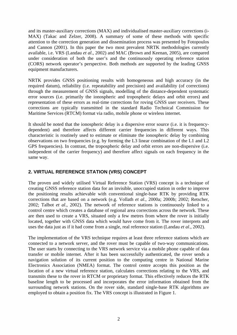
Figure 1. The VRS principle (Landau et al., 2002) The VRS network operator has to perform the following steps (Vollath et al., 2000a): 1) Determine atmospheric and orbit errors with cm-accuracy by fixing the ambiguities of the
baselines within the network, 2) Simulate the position of the VRS by geometrically displacing the data of the reference
station closest to the rover, 3) Interpolate the network errors at the VRS location using linear or more sophisticated
models, and 4) Transmit the corrections to the rover in real-time. 3. MASTER-AUXILIARY CONCEPT (MAC) The relatively new Master-Auxiliary Concept (MAC) was introduced by Euler et al. (2001) and has been shown to deliver high-quality results (e.g. Euler et al., 2002; 2003). It is designed to transmit all relevant correction data from a CORS network to the rover in a highly compact form by representing ambiguity-levelled observation data as correction differences of dispersive and non-dispersive data for each satellite-receiver pair. Two reference stations are said to be on a common ambiguity level if the integer ambiguities for each phase range (satellite-receiver pair) have been removed (or adjusted) so that the integer ambiguities cancel when double-differences (involving two receivers and two satellites) are formed during processing (Brown et al., 2005). The determination of integer ambiguities between the reference stations is the fundamental functionality of network processing software. Reducing the original raw reference station observations onto the same ambiguity level leaves the general properties of the carrier phase observations (ionospheric and tropospheric effects, antenna phase centre variations, etc.) untouched, since only integer numbers have been introduced (RTCM, 2007). An application accessing ambiguity-levelled observations of a single reference station will not see any difference since the modelling requirements within the application are identical. However, when an application uses the observations of more than one reference station, it will no longer have to account for integer ambiguities between the reference stations on the same ambiguity level. This means that a rover receiving and utilising ambiguity-levelled observations of more than one reference station may switch from one reference station to another without re-initialisation of its filter. In order to reduce the volume of data to be transmitted for a network, full correction and coordinate information is sent only for a single reference station (the master station). For all other stations in the network or sub-network (the auxiliary stations), correction differences
4
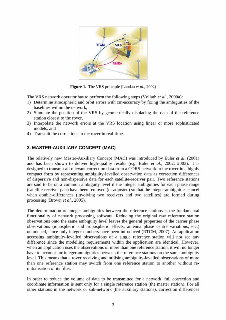
and coordinate differences are transmitted. Splitting the corrections into dispersive and non-dispersive components further reduces the bandwidth required since tropospheric and orbit errors are known to only change slowly over time, so the data rate does not need to be as high as for the dispersive error. Since the master station is used simply for data transmission purposes and plays no special role in the computation of corrections, it does not need to be the closest reference station to the rover (Brown and Keenan, 2005). The user can utilise these NRTK messages either in broadcast mode (one-way communications) or in automatic mode (two-way communications). In broadcast mode the master station is predetermined by the network operator, while it will be the station closest to the rover in automatic mode. 3.1 Networks, Clusters and Cells For practical reasons, network processing and correction dissemination is based on a tiered system of networks, clusters and cells (Figure 2). A cluster is a sub-network of stations that are processed together to achieve a common ambiguity level. Individual sites within the network may be in more than one cluster, allowing overlap between clusters. It should be noted that different clusters may have different ambiguity levels. A cell is a selection of at least three sites from a single cluster consisting of one master station and a number of auxiliary stations. The cell is used to generate the so-called mater-auxiliary corrections for the user (Brown and Keenan, 2005).
Network i
Cluster 2
Cluster 1
Cluster 3
Network i
Cluster 2
Cluster 1
Cluster 3
Network i
Cluster 2
Cluster 1
Cluster 3
Cluster n
Cell 1Cell 2
Cell 3
Cluster n
Cell 1Cell 2
Cell 3
Cluster n
Cell 1Cell 2
Cell 3
Figure 2. (a) A network consisting of several clusters, and (b) a cluster providing master-auxiliary corrections to several rovers, with each rover using an appropriate cell based on its location (Brown et
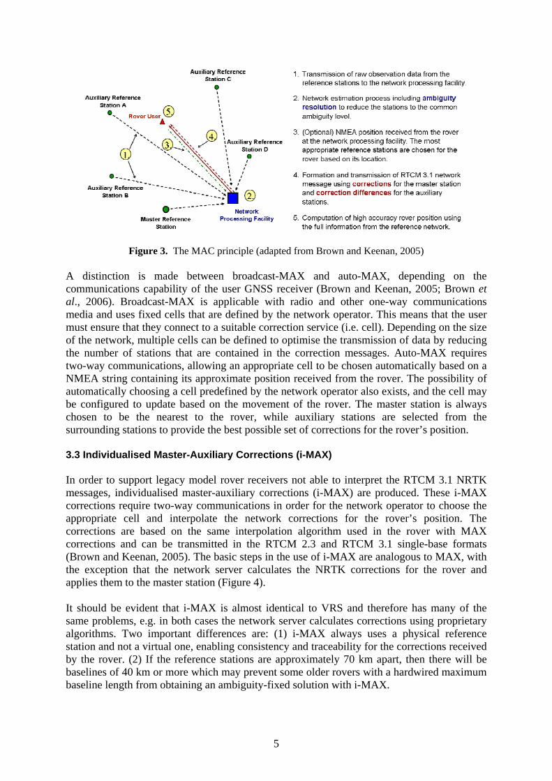
al., 2006) 3.2 Master-Auxiliary Corrections (MAX) The master-auxiliary corrections (MAX) contain the network corrections as specified by the MAC philosophy. The interpolation of the network corrections is performed by the rover using the full information of the network but is only available for rovers that support RTCM 3.1 network messages. MAX corrections are available in both one-way and two-way communications mode. The generation of MAX corrections is explained in Figure 3. It is important to note that if network corrections are not available (e.g. because not enough satellite-receiver pairs are ambiguity-fixed) then no corrections will be sent, and the user must consciously decide to switch to a single-base solution.
(a) (b)
5
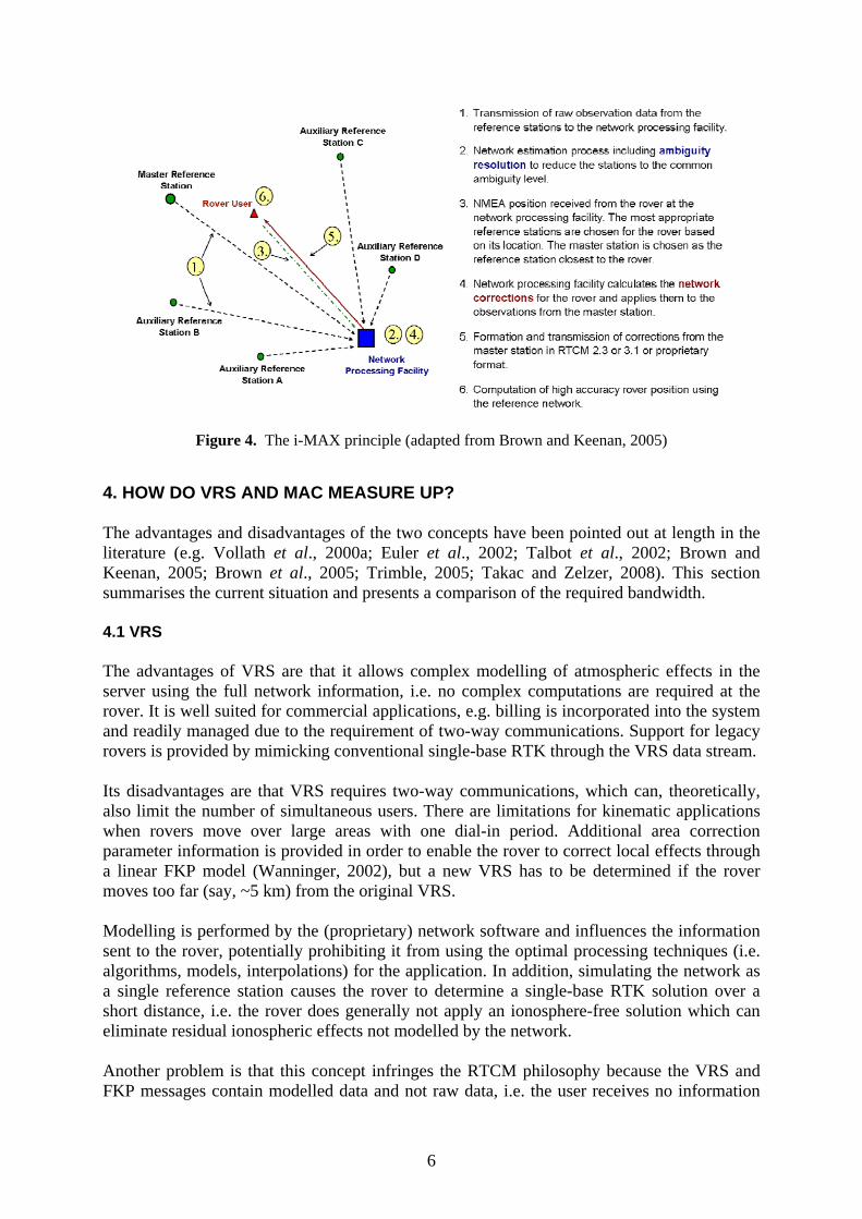
Figure 3. The MAC principle (adapted from Brown and Keenan, 2005) A distinction is made between broadcast-MAX and auto-MAX, depending on the communications capability of the user GNSS receiver (Brown and Keenan, 2005; Brown et al., 2006). Broadcast-MAX is applicable with radio and other one-way communications media and uses fixed cells that are defined by the network operator. This means that the user must ensure that they connect to a suitable correction service (i.e. cell). Depending on the size of the network, multiple cells can be defined to optimise the transmission of data by reducing the number of stations that are contained in the correction messages. Auto-MAX requires two-way communications, allowing an appropriate cell to be chosen automatically based on a NMEA string containing its approximate position received from the rover. The possibility of automatically choosing a cell predefined by the network operator also exists, and the cell may be configured to update based on the movement of the rover. The master station is always chosen to be the nearest to the rover, while auxiliary stations are selected from the surrounding stations to provide the best possible set of corrections for the rover’s position. 3.3 Individualised Master-Auxiliary Corrections (i-MAX) In order to support legacy model rover receivers not able to interpret the RTCM 3.1 NRTK messages, individualised master-auxiliary corrections (i-MAX) are produced. These i-MAX corrections require two-way communications in order for the network operator to choose the appropriate cell and interpolate the network corrections for the rover’s position. The corrections are based on the same interpolation algorithm used in the rover with MAX corrections and can be transmitted in the RTCM 2.3 and RTCM 3.1 single-base formats (Brown and Keenan, 2005). The basic steps in the use of i-MAX are analogous to MAX, with the exception that the network server calculates the NRTK corrections for the rover and applies them to the master station (Figure 4). It should be evident that i-MAX is almost identical to VRS and therefore has many of the same problems, e.g. in both cases the network server calculates corrections using proprietary algorithms. Two important differences are: (1) i-MAX always uses a physical reference station and not a virtual one, enabling consistency and traceability for the corrections received by the rover. (2) If the reference stations are approximately 70 km apart, then there will be baselines of 40 km or more which may prevent some older rovers with a hardwired maximum baseline length from obtaining an ambiguity-fixed solution with i-MAX.
6
Figure 4. The i-MAX principle (adapted from Brown and Keenan, 2005) 4. HOW DO VRS AND MAC MEASURE UP? The advantages and disadvantages of the two concepts have been pointed out at length in the literature (e.g. Vollath et al., 2000a; Euler et al., 2002; Talbot et al., 2002; Brown and Keenan, 2005; Brown et al., 2005; Trimble, 2005; Takac and Zelzer, 2008). This section summarises the current situation and presents a comparison of the required bandwidth. 4.1 VRS The advantages of VRS are that it allows complex modelling of atmospheric effects in the server using the full network information, i.e. no complex computations are required at the rover. It is well suited for commercial applications, e.g. billing is incorporated into the system and readily managed due to the requirement of two-way communications. Support for legacy rovers is provided by mimicking conventional single-base RTK through the VRS data stream. Its disadvantages are that VRS requires two-way communications, which can, theoretically, also limit the number of simultaneous users. There are limitations for kinematic applications when rovers move over large areas with one dial-in period. Additional area correction parameter information is provided in order to enable the rover to correct local effects through a linear FKP model (Wanninger, 2002), but a new VRS has to be determined if the rover moves too far (say, ~5 km) from the original VRS. Modelling is performed by the (proprietary) network software and influences the information sent to the rover, potentially prohibiting it from using the optimal processing techniques (i.e. algorithms, models, interpolations) for the application. In addition, simulating the network as a single reference station causes the rover to determine a single-base RTK solution over a short distance, i.e. the rover does generally not apply an ionosphere-free solution which can eliminate residual ionospheric effects not modelled by the network. Another problem is that this concept infringes the RTCM philosophy because the VRS and FKP messages contain modelled data and not raw data, i.e. the user receives no information
7
about the size of the errors or corrections. Finally, there are possible legal issues in regards to traceability since the GNSS correction data are not directly linked to a real, physical reference station. However, it should be noted that RTCM message 1032 (see section 4.4) can be used to address this issue by providing the position of the closest physical reference station. 4.2 MAC The advantages of MAC are that it allows both one-way and two-way communications and provides support for legacy rover receivers through i-MAX. Complete information on the prevailing error sources is made available to the rover through RTCM network messages, thereby facilitating the use of more intelligent positioning algorithms in the determination of the rover’s position. MAC conforms to RTCM philosophy by transmitting unmodelled (albeit ambiguity-levelled) reference station data to the rover. The exception is i-MAX, which uses proprietary software to determine the corrections. MAC also has advantages for kinematic applications when the rover moves large distances. In auto-MAX mode, a different cell is formed instantly when the rover moves. This is possible since the entire cluster is on the same ambiguity level. Finally, it offers clear legal traceability since the GNSS correction data are directly linked to a real reference station. It is also noteworthy that VRS as well as FKP, MAX and i-MAX can all be inferred from MAC data (Takac and Zelzer, 2008). The disadvantages of MAC are that billing is more complex for commercial users in broadcast mode. The rover is required to perform more of the processing, which may influence the expected trend towards “dumb” rovers for mass-market, non-survey applications in the future. In broadcast mode, the user needs to consciously select a certain cell which is predefined by the network operator and may not be ideal. 4.3 Performance In a direct comparison to VRS and FKP, MAC demonstrated increased performance in terms of time-to-fix, reliability of ambiguity resolution and accuracy for the rover, even though a lower update rate of 5 seconds was used for the network corrections (Brown et al., 2006). Very recently, the performance of Trimble’s VRS Now and Leica Geosystems’ SmartNet was compared extensively across the United Kingdom in order to quantify the achievable accuracy with VRS and MAC, and to provide a basis for NRTK best practice guidelines (Edwards et al., 2008). It was found that both commercial NRTK systems provided similar levels of overall accuracy, i.e. 10-20 mm in the horizontal component and 15-35 mm in the vertical component at the one-sigma level (67%). However, users were urged to pay close attention to coordinate quality (CQ) indicators provided by the rover equipment and be aware that overly optimistic CQ values can be obtained under severely limited satellite visibility and multipath conditions. The adoption of the mean of two 3-minute averaged observation windows separated by 20-45 minutes was shown to reduce errors by about 5 mm, particularly in the vertical component. The use of windowing techniques was also recommended if the height difference between the user and the nearest reference station(s) exceeds 250 m.
8
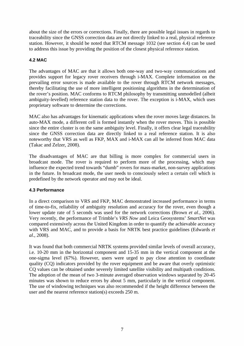
4.4 Bandwidth The data volume to be transmitted between the reference station network and the rover is generally expressed in bits per second (bps). Several theoretical comparisons of the bandwidth necessary to support the VRS and MAC principles for NRTK have been published (e.g. Trimble, 2005; Brown et al., 2006). However, generally it is unclear how the presented values were actually computed. This section compares theoretically derived bandwidths with values that were empirically determined during a field test utilising several CORSnet-NSW stations. CORSnet-NSW (LPMA, 2009; White et al., 2009) was formerly known as SydNET and is currently being expanded by the Land and Property Management Authority (formerly the Department of Lands) to provide state-wide coverage across NSW. Table 1 lists the main RTCM 3.1 messages required for GPS-only NRTK and their theoretical bandwidths. Note that ns refers to the number of satellites, in this case chosen to be 12. A transport layer of 48 bits containing information such as the preamble, message length and check sum, is included in the resulting bandwidth.
Table 1. Theoretical bandwidth of the main RTCM 3.1 messages for 12 satellites and including a transport layer of 48 bits
Message Description No. of Data Bytes Bandwidth (bps)
1004 Extended L1&L2 GPS RTK Observables 8 + 15.625*ns 196 1616 1006 Stationary RTK Ref. Stn. ARP with Ant. Hgt. 21 21 216 1008 Antenna Descriptor & Serial Number 6-68 6 96 1014 Network Auxiliary Station Data 14.625 15 168
1017 GPS Combined Geometric and Ionospheric Correction Differences 9 + 6.625*ns 89 760
1030 GPS Network RTK Residual Message 7 + 6.125*ns 81 696 1032 Physical Reference Station Position Message 19.5 20 208
The following theoretical comparison considers only the messages listed in Table 1 since any additional information does not need to be transmitted at a high data rate and the size of any proprietary messages is unknown. Hence, it only gives an indication of the relative volume of data to be transmitted for VRS and MAC operation. The theoretical bandwidths (BW) are determined by combining the relevant messages and specifying their update rates:
1032103210301030100810081006100610041004 rRTCMrRTCMrRTCMrRTCMrRTCMBWVRS ⋅+⋅+⋅+⋅+⋅= (1)
10321032100810081006100610041004 rRTCMrRTCMrRTCMrRTCMBW MAXi ⋅+⋅+⋅+⋅=− (2)
aux1017101710141014
100810081006100610041004
nrRTCMrRTCMrRTCMrRTCMrRTCMBWMAC
⋅⋅+⋅+⋅+⋅+⋅= (3)
Where RTCMi and ri represent the RTCM message type and its update rate, respectively, and naux is the number of auxiliary stations used. It should be noted that the naux term is not applied to message 1014 in equation (3), although this message contains data for only one auxiliary station. However, it is not required to update message 1014 at a high rate, therefore a rate of 1 second would refer to one auxiliary station per second. This effectively reduces the bandwidth but can, on the other hand, increase the time-to-fix, particularly for larger cells.
9
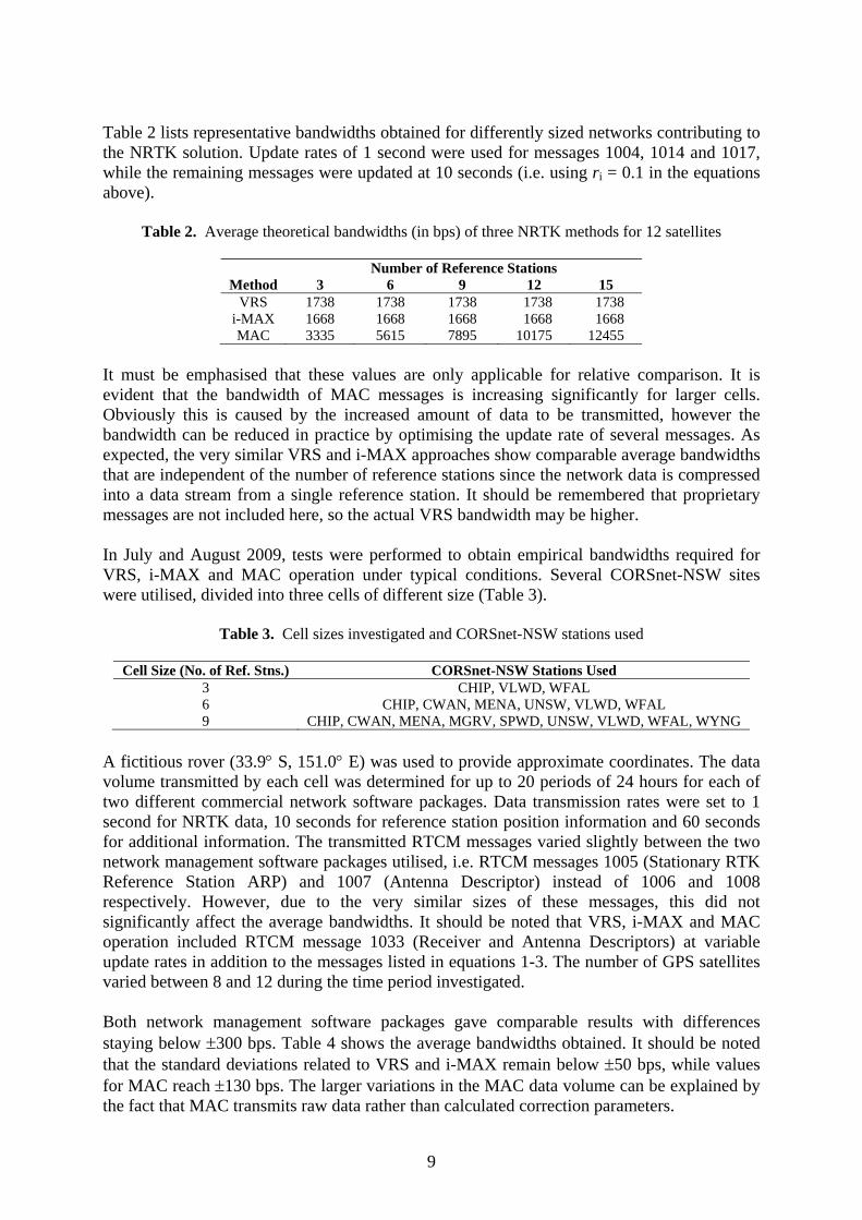
Table 2 lists representative bandwidths obtained for differently sized networks contributing to the NRTK solution. Update rates of 1 second were used for messages 1004, 1014 and 1017, while the remaining messages were updated at 10 seconds (i.e. using ri = 0.1 in the equations above).
Table 2. Average theoretical bandwidths (in bps) of three NRTK methods for 12 satellites
Number of Reference Stations Method 3 6 9 12 15
VRS 1738 1738 1738 1738 1738 i-MAX 1668 1668 1668 1668 1668 MAC 3335 5615 7895 10175 12455
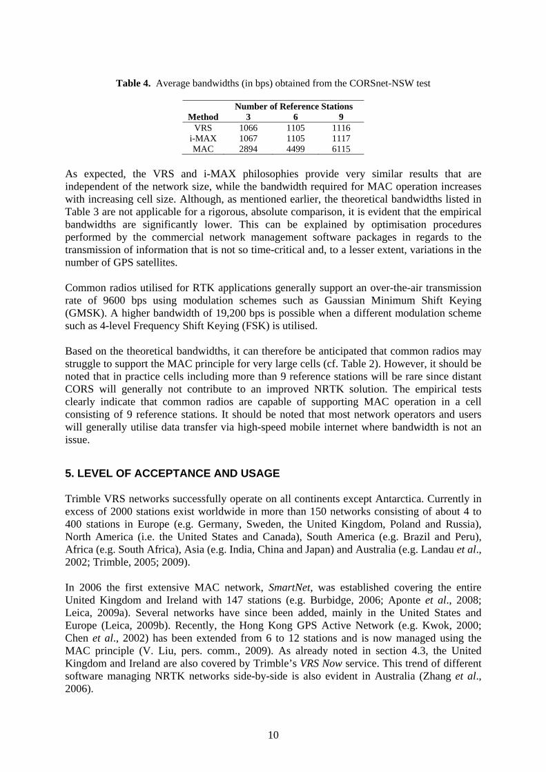
It must be emphasised that these values are only applicable for relative comparison. It is evident that the bandwidth of MAC messages is increasing significantly for larger cells. Obviously this is caused by the increased amount of data to be transmitted, however the bandwidth can be reduced in practice by optimising the update rate of several messages. As expected, the very similar VRS and i-MAX approaches show comparable average bandwidths that are independent of the number of reference stations since the network data is compressed into a data stream from a single reference station. It should be remembered that proprietary messages are not included here, so the actual VRS bandwidth may be higher. In July and August 2009, tests were performed to obtain empirical bandwidths required for VRS, i-MAX and MAC operation under typical conditions. Several CORSnet-NSW sites were utilised, divided into three cells of different size (Table 3).
Table 3. Cell sizes investigated and CORSnet-NSW stations used
Cell Size (No. of Ref. Stns.) CORSnet-NSW Stations Used 3 CHIP, VLWD, WFAL 6 CHIP, CWAN, MENA, UNSW, VLWD, WFAL 9 CHIP, CWAN, MENA, MGRV, SPWD, UNSW, VLWD, WFAL, WYNG
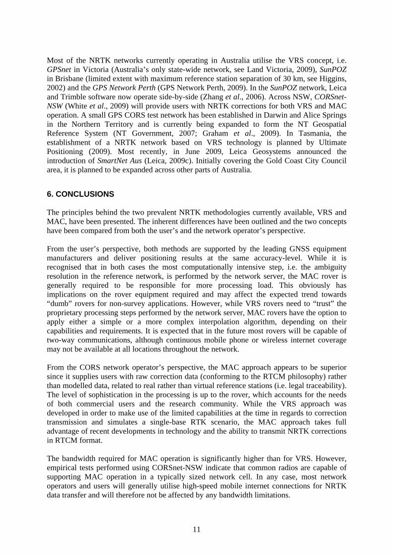
A fictitious rover (33.9° S, 151.0° E) was used to provide approximate coordinates. The data volume transmitted by each cell was determined for up to 20 periods of 24 hours for each of two different commercial network software packages. Data transmission rates were set to 1 second for NRTK data, 10 seconds for reference station position information and 60 seconds for additional information. The transmitted RTCM messages varied slightly between the two network management software packages utilised, i.e. RTCM messages 1005 (Stationary RTK Reference Station ARP) and 1007 (Antenna Descriptor) instead of 1006 and 1008 respectively. However, due to the very similar sizes of these messages, this did not significantly affect the average bandwidths. It should be noted that VRS, i-MAX and MAC operation included RTCM message 1033 (Receiver and Antenna Descriptors) at variable update rates in addition to the messages listed in equations 1-3. The number of GPS satellites varied between 8 and 12 during the time period investigated. Both network management software packages gave comparable results with differences staying below ±300 bps. Table 4 shows the average bandwidths obtained. It should be noted that the standard deviations related to VRS and i-MAX remain below ±50 bps, while values for MAC reach ±130 bps. The larger variations in the MAC data volume can be explained by the fact that MAC transmits raw data rather than calculated correction parameters.
10
Table 4. Average bandwidths (in bps) obtained from the CORSnet-NSW test
Number of Reference Stations
Method 3 6 9 VRS 1066 1105 1116
i-MAX 1067 1105 1117 MAC 2894 4499 6115
As expected, the VRS and i-MAX philosophies provide very similar results that are independent of the network size, while the bandwidth required for MAC operation increases with increasing cell size. Although, as mentioned earlier, the theoretical bandwidths listed in Table 3 are not applicable for a rigorous, absolute comparison, it is evident that the empirical bandwidths are significantly lower. This can be explained by optimisation procedures performed by the commercial network management software packages in regards to the transmission of information that is not so time-critical and, to a lesser extent, variations in the number of GPS satellites. Common radios utilised for RTK applications generally support an over-the-air transmission rate of 9600 bps using modulation schemes such as Gaussian Minimum Shift Keying (GMSK). A higher bandwidth of 19,200 bps is possible when a different modulation scheme such as 4-level Frequency Shift Keying (FSK) is utilised. Based on the theoretical bandwidths, it can therefore be anticipated that common radios may struggle to support the MAC principle for very large cells (cf. Table 2). However, it should be noted that in practice cells including more than 9 reference stations will be rare since distant CORS will generally not contribute to an improved NRTK solution. The empirical tests clearly indicate that common radios are capable of supporting MAC operation in a cell consisting of 9 reference stations. It should be noted that most network operators and users will generally utilise data transfer via high-speed mobile internet where bandwidth is not an issue. 5. LEVEL OF ACCEPTANCE AND USAGE Trimble VRS networks successfully operate on all continents except Antarctica. Currently in excess of 2000 stations exist worldwide in more than 150 networks consisting of about 4 to 400 stations in Europe (e.g. Germany, Sweden, the United Kingdom, Poland and Russia), North America (i.e. the United States and Canada), South America (e.g. Brazil and Peru), Africa (e.g. South Africa), Asia (e.g. India, China and Japan) and Australia (e.g. Landau et al., 2002; Trimble, 2005; 2009). In 2006 the first extensive MAC network, SmartNet, was established covering the entire United Kingdom and Ireland with 147 stations (e.g. Burbidge, 2006; Aponte et al., 2008; Leica, 2009a). Several networks have since been added, mainly in the United States and Europe (Leica, 2009b). Recently, the Hong Kong GPS Active Network (e.g. Kwok, 2000; Chen et al., 2002) has been extended from 6 to 12 stations and is now managed using the MAC principle (V. Liu, pers. comm., 2009). As already noted in section 4.3, the United Kingdom and Ireland are also covered by Trimble’s VRS Now service. This trend of different software managing NRTK networks side-by-side is also evident in Australia (Zhang et al., 2006).
11
Most of the NRTK networks currently operating in Australia utilise the VRS concept, i.e. GPSnet in Victoria (Australia’s only state-wide network, see Land Victoria, 2009), SunPOZ in Brisbane (limited extent with maximum reference station separation of 30 km, see Higgins, 2002) and the GPS Network Perth (GPS Network Perth, 2009). In the SunPOZ network, Leica and Trimble software now operate side-by-side (Zhang et al., 2006). Across NSW, CORSnet-NSW (White et al., 2009) will provide users with NRTK corrections for both VRS and MAC operation. A small GPS CORS test network has been established in Darwin and Alice Springs in the Northern Territory and is currently being expanded to form the NT Geospatial Reference System (NT Government, 2007; Graham et al., 2009). In Tasmania, the establishment of a NRTK network based on VRS technology is planned by Ultimate Positioning (2009). Most recently, in June 2009, Leica Geosystems announced the introduction of SmartNet Aus (Leica, 2009c). Initially covering the Gold Coast City Council area, it is planned to be expanded across other parts of Australia. 6. CONCLUSIONS The principles behind the two prevalent NRTK methodologies currently available, VRS and MAC, have been presented. The inherent differences have been outlined and the two concepts have been compared from both the user’s and the network operator’s perspective. From the user’s perspective, both methods are supported by the leading GNSS equipment manufacturers and deliver positioning results at the same accuracy-level. While it is recognised that in both cases the most computationally intensive step, i.e. the ambiguity resolution in the reference network, is performed by the network server, the MAC rover is generally required to be responsible for more processing load. This obviously has implications on the rover equipment required and may affect the expected trend towards “dumb” rovers for non-survey applications. However, while VRS rovers need to “trust” the proprietary processing steps performed by the network server, MAC rovers have the option to apply either a simple or a more complex interpolation algorithm, depending on their capabilities and requirements. It is expected that in the future most rovers will be capable of two-way communications, although continuous mobile phone or wireless internet coverage may not be available at all locations throughout the network. From the CORS network operator’s perspective, the MAC approach appears to be superior since it supplies users with raw correction data (conforming to the RTCM philosophy) rather than modelled data, related to real rather than virtual reference stations (i.e. legal traceability). The level of sophistication in the processing is up to the rover, which accounts for the needs of both commercial users and the research community. While the VRS approach was developed in order to make use of the limited capabilities at the time in regards to correction transmission and simulates a single-base RTK scenario, the MAC approach takes full advantage of recent developments in technology and the ability to transmit NRTK corrections in RTCM format. The bandwidth required for MAC operation is significantly higher than for VRS. However, empirical tests performed using CORSnet-NSW indicate that common radios are capable of supporting MAC operation in a typically sized network cell. In any case, most network operators and users will generally utilise high-speed mobile internet connections for NRTK data transfer and will therefore not be affected by any bandwidth limitations.
12
While most existing NRTK networks currently operate using the VRS methodology, a further increase in the use of MAC is expected as the spatial community recognises the advantages of this new approach for use with sophisticated rovers. An increase in the number of NRTK networks providing corrections to the user based on both philosophies is envisaged in the intermediate future. It should be emphasised that both concepts are supported by the major equipment manufacturers and this paper does not intend to support any manufacturer in particular. ACKNOWLEDGEMENTS Mr Thomas Yan from the NSW Land and Property Management Authority is gratefully acknowledged for performing the empirical bandwidth tests. Thanks to Dr Nick Talbot from Trimble Navigation and Dr Neil Brown from Leica Geosystems for providing valuable feedback and clarification. REFERENCES Aponte J, Meng X, Moore T, Hill C, Burbidge M (2008) Investigating the impact of the commercial
GSM/GPRS communications on the availability of the network based RTK GNSS service, Proceedings of ION GNSS 2008, Savannah, GA, 406-411
Brown N, Geisler I, Troyer L (2006) RTK rover performance using the Master-Auxiliary Concept, Journal of Global Positioning Systems 5(1-2): 135-144
Brown N, Keenan R (2005) Take it to the max! – An introduction to the philosophy behind Leica Geosystems’ SpiderNET revolutionary network RTK software and algorithms, White paper, http://www.leicaadvantage.com/support/ReferenceStations1200/ReferenceStationTechnicalPapers.cfm (accessed Sep 2009)
Brown N, Keenan R, Richter B, Troyer L (2005) Advances in ambiguity resolution for RTK applications using the new RTCM V3.0 master-auxiliary messages, Proceedings of ION GNSS 2005, Long Beach, CA, 73-80
Burbidge M (2006) Introducing SmartNet-UK, the first Leica Geosystems commercial network RTK correction service, Proceedings of XXIII International FIG Congress, Munich, Germany, http://www.fig.net/pub/fig2006/techprog.htm (accessed Sep 2009)
Chen W, Hu C, Ding X, Chen Y, Kwok S (2002) Critical issues on GPS RTK operation using Hong Kong GPS Active Network, Journal of Geospatial Engineering 4(1): 31-40
Edwards S, Clarke P, Goebell S, Penna N (2008) An examination of commercial network RTK GPS services in Great Britain, TSA report, http://www.trimble.com/pdf/TSA_Report.pdf (accessed Sep 2009)
Euler H-J, Keenan CR, Zebhauser BE, Wübbena G (2001) Study of a simplified approach in utilizing information from permanent reference station arrays, Proceedings of ION GPS 2001, Salt Lake City, UT, 379-391
Euler H-J, Zebhauser BE, Townsend BR, Wübbena G (2002) Comparison of different proposals for reference station network information distribution formats, Proceedings of ION GPS 2002, Portland, OR, 2349-2358
Euler H-J, Zelzer O, Takac F, Zebhauser BE (2003) Applicability of standardized network RTK message for surveying rovers, Proceedings of ION GPS/GNSS 2003, Portland, OR, 1361-1369
Fotopoulos G, Cannon ME (2001) An overview of multi-reference station methods for cm-level positioning, GPS Solutions 4(3): 1-10
GPS Network Perth (2009) http://www.gpsnetworkperth.com.au/ (accessed Sep 2009)
13
Graham K, Mann E, Peterson A, Sarib R (2009) Status of the NT geospatial reference system, Proceedings of SSC2009, Adelaide, Australia, 133-153
Higgins M (2002) Australia’s changing surveying infrastructure from marks in the ground to virtual reference stations, Proceedings of FIG XXII International Congress, Washington, DC, paper TS5.6
Kwok SC (2000) The Hong Kong GPS network and reference stations, Journal of Geospatial Engineering 2(2): 57-65
Landau H, Vollath U, Chen X (2002) Virtual reference station systems, Journal of Global Positioning Systems 1(2): 137-143
Land Victoria (2009) GPSnet, http://www.land.vic.gov.au/gpsnet (accessed Sep 2009) Leica (2009a) SmartNet, http://smartnet.leica-geosystems.co.uk/ (accessed Sep 2009) Leica (2009b) SmartNet Europe, http://smartnet.leica-geosystems.eu/ (accessed Sep 2009) Leica (2009c) SmartNet Aus, http://smartnetaus.com/ (accessed Sep 2009) LPMA (2009) CORSnet-NSW, http://corsnet.lpma.nsw.gov.au (accessed Sep 2009) NT Government (2007) Land Information Newsletter, http://www.nt.gov.au/lands/lis/newsletter/2007/
october.shtml (accessed Sep 2009) Retscher G (2002) Accuracy performance of virtual reference station (VRS) networks, Journal of
Global Positioning Systems 1(1): 40-47 Rizos C (2002) Network RTK research and implementation – A geodetic perspective, Journal of
Global Positioning Systems 1(2): 144-150 RTCM (2007) RTCM Standard 10403.1: Differential GNSS (Global Navigation Satellite Systems)
services – version 3, including Amendments 1 and 2. Takac F, Zelzer O (2008) The relationship between network RTK solutions MAC, VRS, PRS, FKP
and i-MAX, Proceedings of ION GNSS 2008, Savannah, GA, 348-355 Talbot N, Lu G, Allison T, Vollath U (2002) Broadcast network RTK – Transmission standards and
results, Proceedings of ION GPS 2002, Portland, OR, 2379-2387 Trimble (2005) Support of network formats by Trimble GPSNet network RTK solution, White paper,
http://www.trimble.com/survey_wp_scalable.asp?Nav=Collection-33413 (accessed Sep 2009) Trimble (2009) VRS installations, http://www.trimble.com/infrastructure/vrs-installations.aspx
(accessed Sep 2009) Ultimate Positioning (2009) TASpos – Tasmania’s Trimble GNSS Network from Ultimate
Positioning, http://www.ultimatepositioning.com/pages/TASpos.htm (accessed Sep 2009) Vollath U, Buecherl A, Landau H, Pagels C, Wagner B (2000a) Multi-base RTK positioning using
virtual reference stations, Proceedings of ION GPS 2000, Salt Lake City, UT, 123-131 Vollath U, Buecherl A, Landau H, Pagels C, Wagner B (2000b) Long-range RTK positioning using
virtual reference stations, Proceedings of ION GPS 2000, Salt Lake City, UT, 1143-1147 Vollath U, Landau H, Chen X, Doucet K, Pagels C (2002) Network RTK versus single base RTK –
Understanding the error characteristics, Proceedings of ION GPS 2002, Portland, OR, 2774-2781
Wanninger L (2002) Virtual reference stations for centimetre-level kinematic positioning, Proceedings of ION GPS 2002, Portland, OR, 1400-1407
White A, Yan T, Janssen V, Yates K (2009) CORSnet-NSW: Delivering a state-of-the-art CORS network for New South Wales, Proceedings of IGNSS 2009, Surfers Paradise, Australia
Zhang K, Wu F, Wu S, Rizos C, Roberts C, Ge L, Yan T, Gordini C, Kealy A, Hale M, Ramm P, Asmussen H, Kinlyside D, Harcombe P (2006) Sparse or dense: Challenges of Australian network RTK, Proceedings of IGNSS 2006, Surfers Paradise, Australia