Embed Size (px)
Citation preview
SEEE DIGIBOOK ON ENGINEERING & TECHNOLOGY, VOL. 01, MAY 2018 ALTERNATE ENERGY TECHNOLOGIES
978-81-933187-0-6 © 2018 SEEEPEDIA.ORG Society for Engineering Education Enrichment
Navin Raj.K, [email protected] Dr.V.Geetha, [email protected]
A Comparative study on
various MPPT Techniques used in Solar PV System
K.Navin Raj, Dr. V.Geetha Government College of Technology, Coimbatore, India
[email protected], [email protected]
Abstract— This work presents the performance analysis of MPPT based control of DC-converter for Solar PV system. MPPT techniques like Perturb and Observe (P&O), Incremental conductance (I&C) and Fuzzy Logic Controller (FLC) Algorithms are employed to track the maximum power from the solar panel. The proposed FLC algorithm with DC-DC converter helps in improving the output voltage while considering varying Weather Parameters (VWP) by using Curve Fitting Technique. The P&O, I&C and FLC algorithms used in this project are simulated in the MATLAB environment. The result of the performance parameters at varying weather parameters are compared and analyzed for P&O, I&C and FLC algorithms. From the simulation results it is evident that the proposed algorithm shows better result compared with other algorithms.
Index Terms—Perturb and Observe, Incremental conductance, Fuzzy Logic Controller.
I. INTRODUCTION Among all natural energy sources, PV array systems plays an important role to full fill the requirement of energy demand. Since it is a renewable energy source and no need any maintenance. The electrical energy is converted from solar energy by means of Photovoltaic (PV) modules. Generally, PV modules are employed by the arrangement of series and parallel combination of solar cells. Pure silicon material is used to make solar cells. MPPT technique is implemented in order to get maximum power from solar cell. It controls and correlates the output voltage with battery voltage. But the conversion efficiency is low for MPPT. Because the output gain of MPPT is mainly depends on solar irradiation and temperature. The maximum amount of power can be obtained from current voltage characteristics of the solar array only at one point which corresponds to the knee of curve called as the maximum power point. Control algorithm is necessary to operate the switches in the converter at this instant by load resistance to match that of the PV output. There are different techniques for MPPT such as Perturb and Observe (hill climbing method), Incremental conductance, Fractional Short Circuit Current, Fractional Open Circuit Voltage, Fuzzy Control, Neural Network Control etc. In this paper the characteristic behavior of PV panel is analyzed considering the different operating conditions of irradiance level and different circuit loads with different MPPT techniques for maximum power tracking
II.MATHEMATIC MODELING OF THE PHOTOVOLTAIC SYSTEM
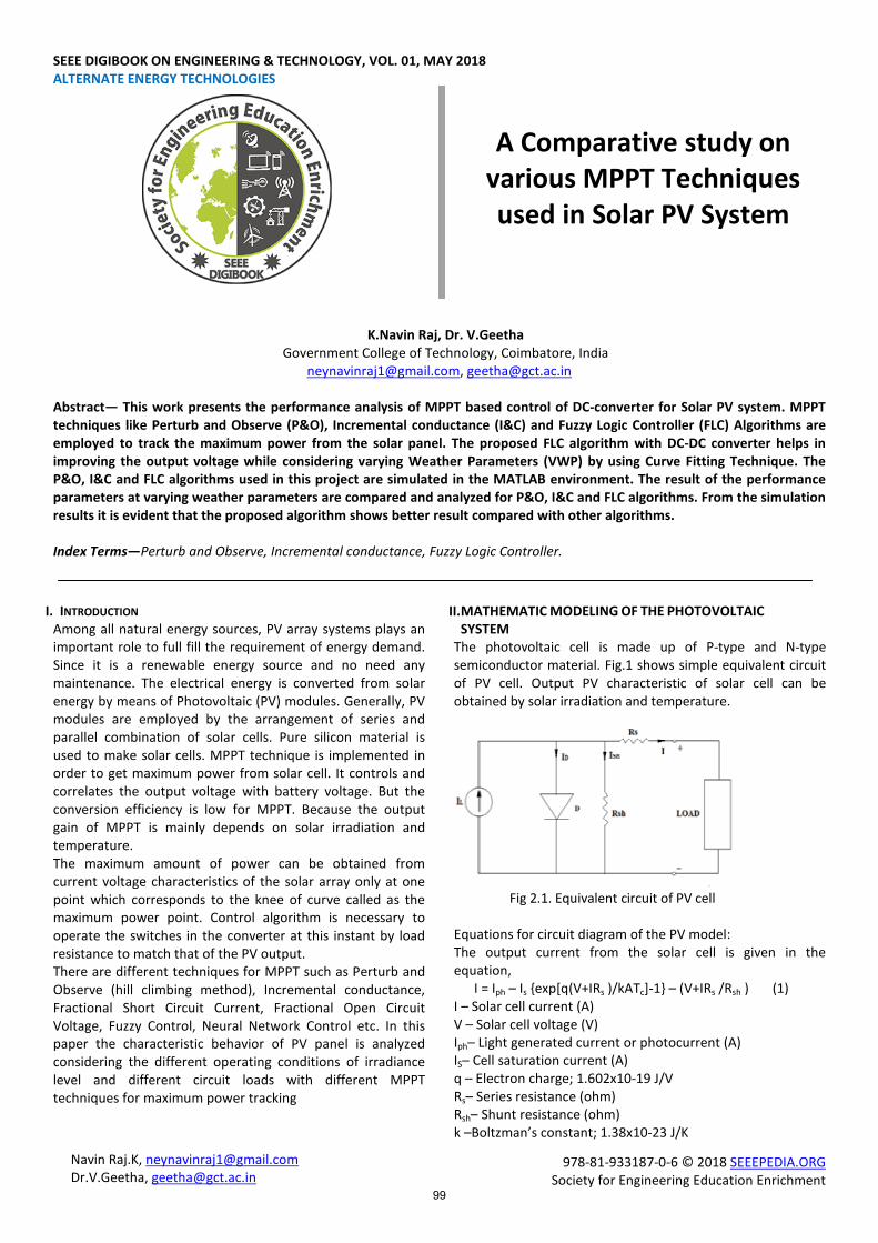
The photovoltaic cell is made up of P-type and N-type semiconductor material. Fig.1 shows simple equivalent circuit of PV cell. Output PV characteristic of solar cell can be obtained by solar irradiation and temperature.
Fig 2.1. Equivalent circuit of PV cell Equations for circuit diagram of the PV model: The output current from the solar cell is given in the equation, I = Iph – Is {exp[q(V+IRs )/kATc]-1} – (V+IRs /Rsh ) (1) I – Solar cell current (A) V – Solar cell voltage (V) Iph– Light generated current or photocurrent (A) IS– Cell saturation current (A) q – Electron charge; 1.602x10⁻¹⁹ J/V Rs– Series resistance (ohm) Rsh– Shunt resistance (ohm) k –Boltzman’s constant; 1.38x10⁻²³ J/K
99
SEEE DIGIBOOK ON ENGINEERING & TECHNOLOGY, VOL. 01, MAY 2018
9978-81-933187-0-6 © 2018 SEEEPEDIA.ORG Society for Engineering Education Enrichment
A – Diode ideality factor Tc– Cell temperature (K) G – Insolation (W/m²) Iph = [Isc + K1 (Tc – Tref )]G (2) ISC–Cell’s short-circuit current at 298 K and 1 kW/m2 Tref–Reference temperature of the cell; 298 K K1– Short circuit temperature coefficient; 0.0017 (A/ºC) IS = IRS (Tc/Tref)
3exp [qEg(Tc – Tref) / TrefTckA] (3) IRS–Cell’s reverse saturation current at a reference temperature and solar radiation Eg– Band-gap energy
III. MAXIMUM POWER POINT TRACKING ALGORITHM MPPT is an electronic DC to DC converter circuit which is connected between solar panel and load. The term maximum power defines that the power at knee point. MPPT only tracks the maximum power even though the input of solar panel is get varied. Then the power is stored into the battery or give it to the load depends on the application.
IV. MATHEMATIC MODELING OF PERTURB AND OBSERVE METHOD The most popular method of MPPT technique is perturb and observe algorithm. It reaches the maximum power by. intentionally perturbing the duty cycle of converter and observing the changes in power. The converter duty cycle is maintained as it is when the converter is operating at the MPP, otherwise duty cycle is periodically adjusted in order to increase the voltage and current of the converter. The algorithm increments or decrements continuously the reference voltage or current based on the previous value of power until reaches the MPP.
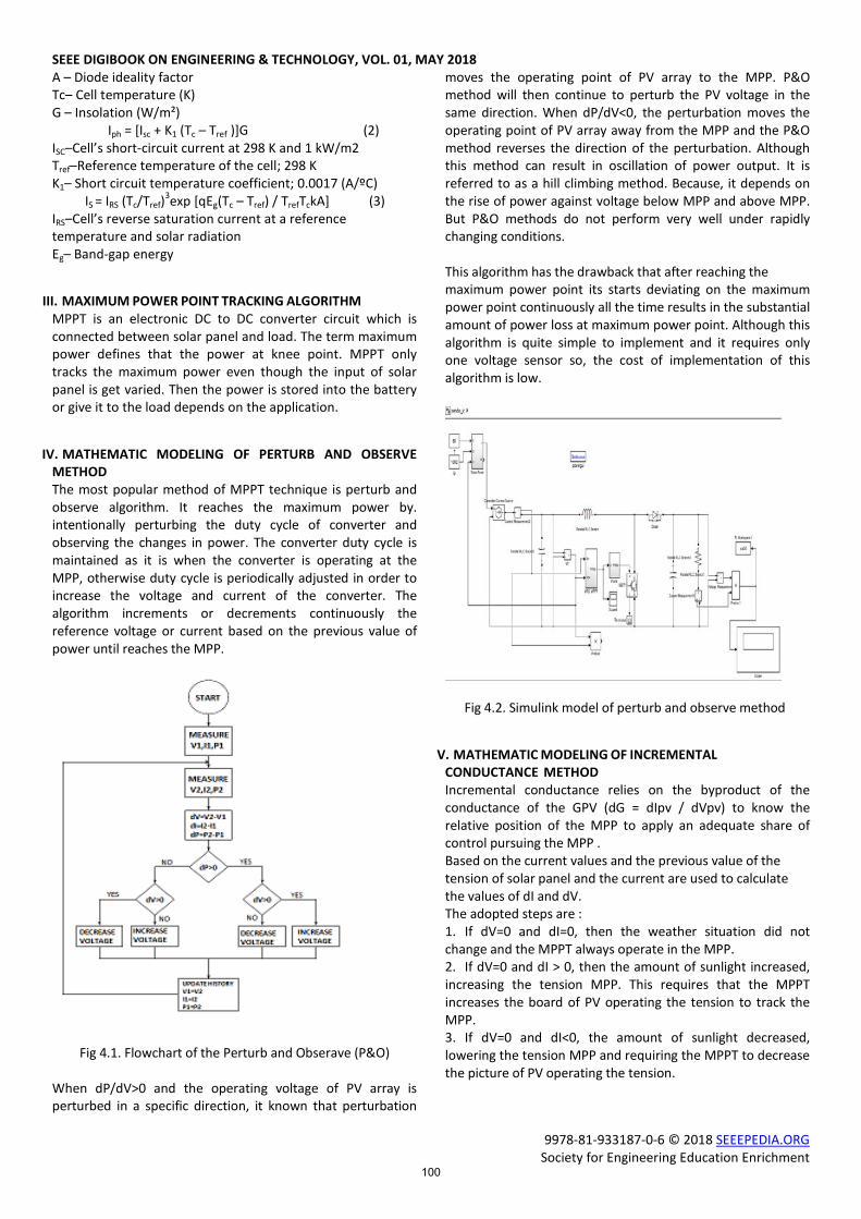
Fig 4.1. Flowchart of the Perturb and Obserave (P&O) When dP/dV>0 and the operating voltage of PV array is perturbed in a specific direction, it known that perturbation
moves the operating point of PV array to the MPP. P&O method will then continue to perturb the PV voltage in the same direction. When dP/dV<0, the perturbation moves the operating point of PV array away from the MPP and the P&O method reverses the direction of the perturbation. Although this method can result in oscillation of power output. It is referred to as a hill climbing method. Because, it depends on the rise of power against voltage below MPP and above MPP. But P&O methods do not perform very well under rapidly changing conditions. This algorithm has the drawback that after reaching the maximum power point its starts deviating on the maximum power point continuously all the time results in the substantial amount of power loss at maximum power point. Although this algorithm is quite simple to implement and it requires only one voltage sensor so, the cost of implementation of this algorithm is low.
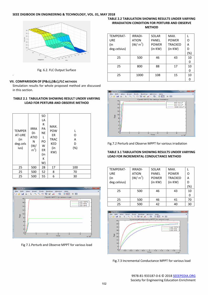
Fig 4.2. Simulink model of perturb and observe method
V. MATHEMATIC MODELING OF INCREMENTAL CONDUCTANCE METHOD Incremental conductance relies on the byproduct of the conductance of the GPV (dG = dIpv / dVpv) to know the relative position of the MPP to apply an adequate share of control pursuing the MPP . Based on the current values and the previous value of the tension of solar panel and the current are used to calculate the values of dI and dV. The adopted steps are : 1. If dV=0 and dI=0, then the weather situation did not change and the MPPT always operate in the MPP. 2. If dV=0 and dI > 0, then the amount of sunlight increased, increasing the tension MPP. This requires that the MPPT increases the board of PV operating the tension to track the MPP. 3. If dV=0 and dI<0, the amount of sunlight decreased, lowering the tension MPP and requiring the MPPT to decrease the picture of PV operating the tension.
100

SEEE DIGIBOOK ON ENGINEERING & TECHNOLOGY, VOL. 01, MAY 2018
9978-81-933187-0-6 © 2018 SEEEPEDIA.ORG Society for Engineering Education Enrichment
Fig .5.1. Flowchart of the Incremental conductance (I&C) method 4. If the changes of the tension and the current are not the zero, the relations in the equation (dI/dV > -I/V,dP/dV>0) and (dI/dV < -I/V, dP/dV<0) can be used to determine the direction in which the tension must be changed to affect the MPP. 5. If (dI/dV > -I/V, dP/dV>0) and the functioning of board of PV The point is to the left of the MPP on the curve of P-V. So, the PV the tension of board must be increased to affect the MPP. 6. If (dI/dV < -I/V, dP/dV < 0) and the PV The board running the point is lying to the right of the MPP on curved, significant P-V La that the tension must be reduced to extend the MPP.
Fig. 5.2 Simulink model of Incremental Conductance method
VI. MATHEMATIC MODELING OF FUZZY LOGIC CONTROL METHOD Fuzzy logic controllers have been introduced in the tracking of the MPP in PV systems. They have the advantage to be robust and relatively simple to design as they do not require the knowledge of the exact model. The proposed FLC method is designed to force VPV to follow the reference voltage (Vmpp). In this paper, Mamdani type Fuzzy Logic Controller of two inputs and one output is used. There are the error E(k), change in error ΔE(k) and its change in the duty cycle ΔD(k),respectively at sampling instant k. The input equation is, (4)
(5) Output equation to FLC can be expressed as: (6) The sign of E(k) indicates the PV module’s MPP either on the left or right of the operating point .
Fig. 6.1.Simulink model of Fuzzy Logic Controller model Basically FLC consists of three basic components: fuzzification, fuzzy inference engine and defuzzification. During fuzzification process, the input variables are normalized and converted to linguistic fuzzy sets by using the triangular membership functions. Due its ease in implementation triangular membership function is used. In this proposed FLC method, “IF- THEN” rules with “AND” logical operator are used. This can e tabulated in Table I. for the defuzzification process ,the linguistic fuzzy sets are converted again into crisp value ΔD as expressed by:
(7)
The result is denormalized to produce the actual duty cycle control signal.
Table I FUZZY RULE- BASED MATRIX
ΔD
ΔE
NB NS Z PS PB
E
NB Z Z PB PB PB
NS Z Z PS PS PS
Z PS Z Z Z NS
PS NS NS NS Z Z
PB NB NB NB Z Z The relationship between the inputs (E, ΔE) and output (ΔD) can be represented in output surface using Matlab/Simulink simulation in fig.7.
101
SEEE DIGIBOOK ON ENGINEERING & TECHNOLOGY, VOL. 01, MAY 2018
9978-81-933187-0-6 © 2018 SEEEPEDIA.ORG Society for Engineering Education Enrichment
Fig. 6.2. FLC Output Surface .
VII. COMPARISION OF (P&O),(I&C),FLC METHODS Simulation results for whole proposed method are discussed in this section. TABLE 2.1 TABULATION SHOWING RESULT UNDER VARYING
LOAD FOR PERTURB AND OBSERVE METHOD
TEMPERAT-URE
(in deg.cels
ius)
IRRADI-
ATION
(W/ m2)
SOLAR
PANEL
POWER (in K
W)
MAX. POW
ER TRACKED (in
KW)
L O A D
(%)
25 500 28 17 100 25 500 52 8 70 25 500 55 6 30
Fig 7.1.Perturb and Observe MPPT for various load
TABLE 2.2 TABULATION SHOWING RESULTS UNDER VARYING IRRADIATION CONDITION FOR PERTURB AND OBSERVE
METHOD
TEMPERAT-URE (in deg.celsius)
IRRADI-ATION (W/ m2)
SOLAR PANEL POWER (in KW)
MAX. POWER TRACKED (in KW)
L O A D (%)
25 500 46 43 100
25 800 88 17 100
25 1000 108 15 100
Fig.7.2 Perturb and Observe MPPT for various irradiation TABLE 3.1 TABULATION SHOWING RESULTS UNDER VARYING LOAD FOR INCREMENTAL CONDUCTANCE METHOD
TEMPERAT-URE (in deg.celsius)
IRRADI-ATION (W/ m2)
SOLAR PANEL POWER (in KW)
MAX. POWER TRACKED (in KW)
L O A D (%)
25 500 46 43 100
25 500 46 41 70 25 500 42 40 30
Fig.7.3 Incremental Conductance MPPT for various load
102
SEEE DIGIBOOK ON ENGINEERING & TECHNOLOGY, VOL. 01, MAY 2018
9978-81-933187-0-6 © 2018 SEEEPEDIA.ORG Society for Engineering Education Enrichment
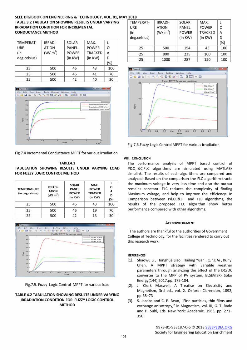
TABLE 3.2 TABULATION SHOWING RESULTS UNDER VARYING IRRADIATION CONDITION FOR INCREMENTAL CONDUCTANCE METHOD
TEMPERAT-URE (in deg.celsius)
IRRADI-ATION (W/ m2)
SOLAR PANEL POWER (in KW)
MAX. POWER TRACKED (in KW)
L O A D (%)
25 500 46 43 100 25 500 46 41 70 25 500 42 40 30
Fig.7.4 Incremental Conductance MPPT for various irradiation
TABLE4.1 TABULATION SHOWING RESULTS UNDER VARYING LOAD FOR FUZZY LOGIC CONTROL METHOD
TEMPERAT-URE (in deg.celsius)
IRRADI-ATION
(W/ m2)
SOLAR PANEL POWER (in KW)
MAX. POWER
TRACKED (in KW)
L O A D
(%) 25 500 46 43 100 25 500 46 19 70 25 500 42 13 30
Fig.7.5. Fuzzy Logic Control MPPT for various load
TABLE 4.2 TABULATION SHOWING RESULTS UNDER VARYING IRRADIATION CONDITION FOR FUZZY LOGIC CONTROL
METHOD
TEMPERAT-URE (in deg.celsius)
IRRADI-ATION (W/ m2)
SOLAR PANEL POWER (in KW)
MAX. POWER TRACKED (in KW)
L O A D (%)
25 500 154 45 100 25 800 235 100 100 25 1000 287 150 100
Fig.7.6.Fuzzy Logic Control MPPT for various irradiation
VIII. CONCLUSION The performance analysis of MPPT based control of P&O,I&C,FLC algorithms are simulated using MATLAB/ simulink. The results of each algorithms are compared and analyzed. Based on the comparison the FLC algorithm tracks the maximum voltage in very less time and also the output remains constant. FLC reduces the complexity of finding Maximum voltage, and help to improve the efficiency. In Comparison between P&O,I&C and FLC algorithms, the results of the proposed FLC algorithm show better performance compared with other algorithms.
ACKNOWLEDGMENT
The authors are thankful to the authorities of Government College of Technology, for the facilities rendered to carry out this research work.
REFERENCES [1]. Shaowu Li , Honghua Liao , Hailing Yuan , Qing Ai , Kunyi
Chen, A MPPT strategy with variable weather parameters through analyzing the effect of the DC/DC converter to the MPP of PV system, ELSEVIER- Solar Energy(144),2017,pp. 175-184.
[2]. J. Clerk Maxwell, A Treatise on Electricity and Magnetism, 3rd ed., vol. 2. Oxford: Clarendon, 1892, pp.68–73
[3]. S. Jacobs and C. P. Bean, “Fine particles, thin films and exchange anisotropy,” in Magnetism, vol. III, G. T. Rado and H. Suhl, Eds. New York: Academic, 1963, pp. 271–350.
103

SEEE DIGIBOOK ON ENGINEERING & TECHNOLOGY, VOL. 01, MAY 2018
9978-81-933187-0-6 © 2018 SEEEPEDIA.ORG Society for Engineering Education Enrichment
[4]. R. Nicole, “Title of paper with only first word capitalized,” J. Name Stand. Abbrev., in press.
[5]. Y. Yorozu, M. Hirano, K. Oka, and Y. Tagawa, “Electron spectroscopy studies on magneto-optical media and plastic substrate interface,” IEEE Transl. J. Magn. Japan, vol. 2, pp. 740–741, August 1987 [Digests 9th Annual Conf. Magnetics Japan, p. 301, 1982].
[6]. M. Young, The Technical Writer's Handbook. Mill Valley, CA: University Science, 1989.
[7]. D. Hohm and M. Ropp, “Comparative study of MPPT algorithms using an experimental, programmable, MPPT test bed,” in Proc. 28th IEEE conf. Rec. Photovolt. Spec. Conf., 2000, pp. 1699-1702.
[8]. T. Esram and P. Chapman, “Comparison of photovoltaic array maximum power point tracking techniques,”IEEE Trans. Energy Convers., vol. 22, no. 2, pp. 439–449, Jun. 2007.
[9]. Fan Zhang, Kary Thanapalan, Andrew Procter, Stephen Carr,and Jon Maddy, “Adaptive Hybrid Maximum Power Point Tracking Method for a Photovoltaic System” IEEE Trans. Energy Convers.(DOI,-10.1109/TEC.), pp. 1-7,March 2013.
104