Embed Size (px)
Citation preview
MS Thesis Defense
A Combined Discrete-dislocation/Scale-dependent Crystal Plasticity Analysis of
Deformation and Fracture in Nanomaterials
A Combined Discrete-dislocation/Scale-dependent Crystal Plasticity Analysis of
Deformation and Fracture in Nanomaterials
Presented by:Derek Columbus
Advisor: Dr. Mica GrujicicDepartment of Mechanical Engineering
Clemson University
Objective
Compare the results of analyses in which two material models, that take different approaches to model plasticity, are used to simulate deformation and fracture in single crystal solids of the mesoscale size range (fraction of micrometer to approximately 100µm) where the geometric length scale is of the same order as relevant material length scales.
Overview of PresentationBrief Description of ModelsI.
Discrete Dislocation Model (Van der Giessen, Needleman 1995)
Crystal Plasticity Model
Results and ComparisonII.
Micro-beam Bending
Mode I Crack
ConclusionsIII.
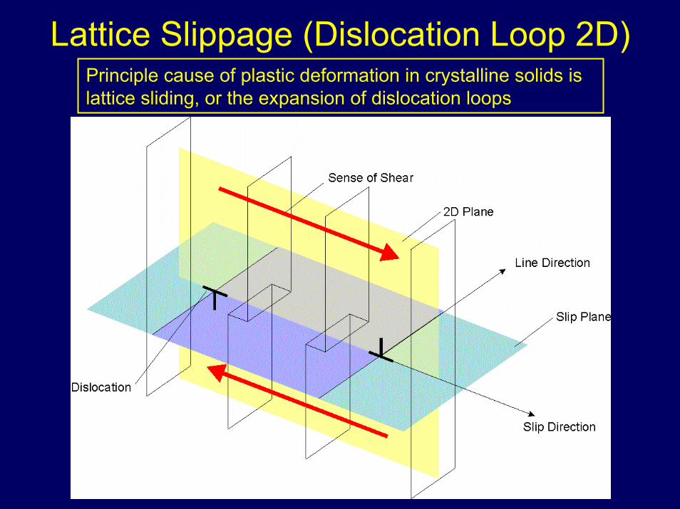
Lattice Slippage (Dislocation Loop 2D)Principle cause of plastic deformation in crystalline solids is lattice sliding, or the expansion of dislocation loops
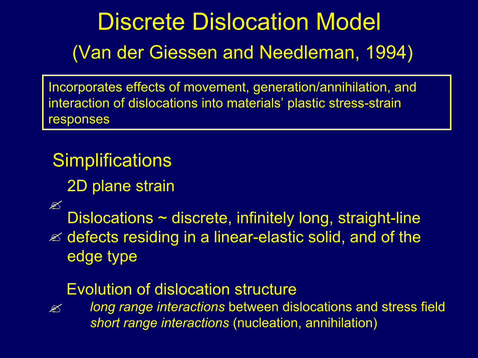
Discrete Dislocation Model(Van der Giessen and Needleman, 1994)
Incorporates effects of movement, generation/annihilation, and interaction of dislocations into materials’ plastic stress-strain responses
Simplifications2D plane strain
Dislocations ~ discrete, infinitely long, straight-line defects residing in a linear-elastic solid, and of the edge type
Evolution of dislocation structurelong range interactions between dislocations and stress fieldshort range interactions (nucleation, annihilation)
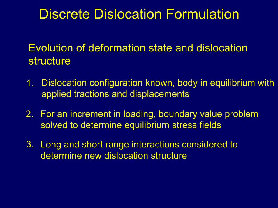
Discrete Dislocation Formulation
Evolution of deformation state and dislocation structure
Dislocation configuration known, body in equilibrium with applied tractions and displacements
1.
2. For an increment in loading, boundary value problem solved to determine equilibrium stress fields
3. Long and short range interactions considered to determine new dislocation structure
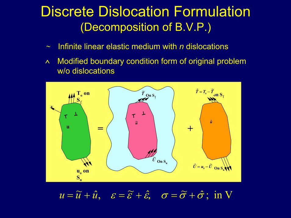
Discrete Dislocation Formulation(Decomposition of B.V.P.)
∼ Infinite linear elastic medium with n dislocations
Modified boundary condition form of original problem w/o dislocations
^
= +
On Su
On Sƒ
u~
T~
U~
on Sƒ
On Su
u
TTT ~ˆ0 −=
UuU ~ˆ0 −=
To on Sƒ
uo on Su
v
u
Vin ˆ~ˆ~,ˆ~ ;+=+=+= σσσ,εεεuuu
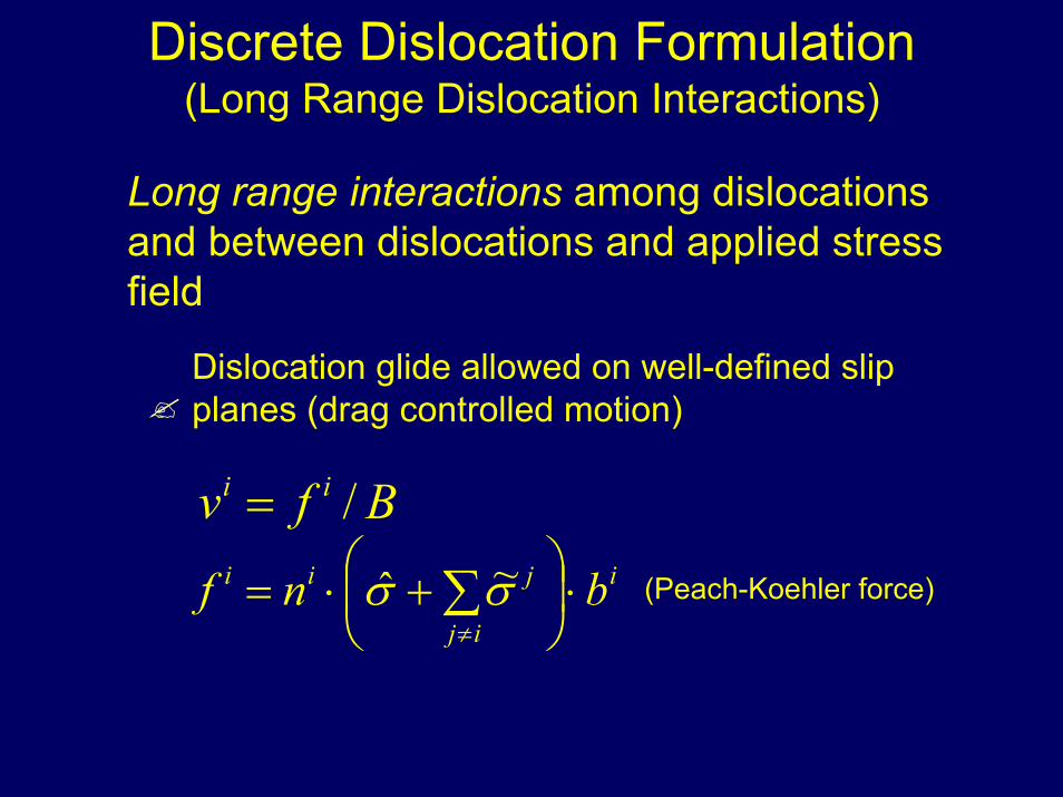
Discrete Dislocation Formulation(Long Range Dislocation Interactions)
Long range interactions among dislocations and between dislocations and applied stress field
Dislocation glide allowed on well-defined slip planes (drag controlled motion)
i
ij
jii bnf ⋅
+⋅= ∑
≠σσ ~ˆ
Bfv ii /=
(Peach-Koehler force)
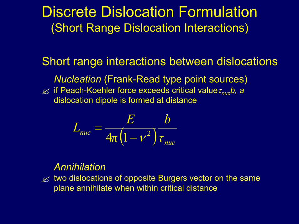
Discrete Dislocation Formulation(Short Range Dislocation Interactions)
Short range interactions between dislocationsNucleation (Frank-Read type point sources)if Peach-Koehler force exceeds critical valueτnucb, a dislocation dipole is formed at distance
( ) nucnuc
bELτν 21π4 −
=
Annihilationtwo dislocations of opposite Burgers vector on the same plane annihilate when within critical distance
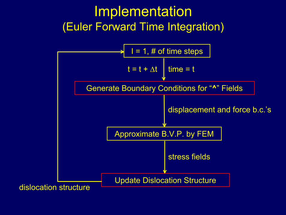
Implementation(Euler Forward Time Integration)
I = 1, # of time steps
Approximate B.V.P. by FEM
Generate Boundary Conditions for “^” Fields
Update Dislocation Structure
stress fields
displacement and force b.c.’s
dislocation structure
t = t + ∆t time = t
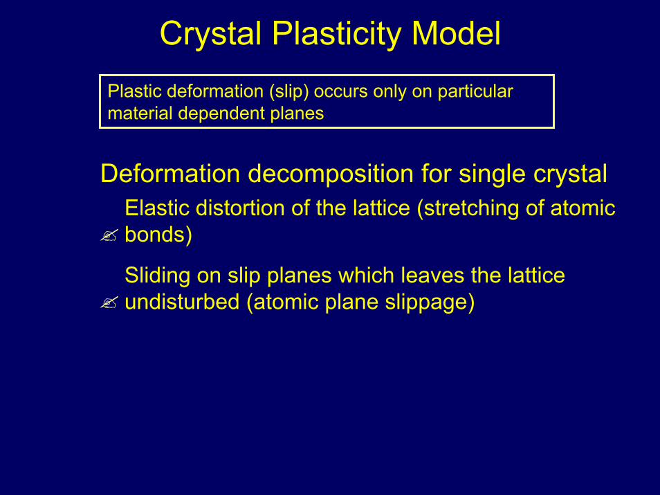
Crystal Plasticity ModelPlastic deformation (slip) occurs only on particular material dependent planes
Deformation decomposition for single crystalElastic distortion of the lattice (stretching of atomic bonds)
Sliding on slip planes which leaves the lattice undisturbed (atomic plane slippage)
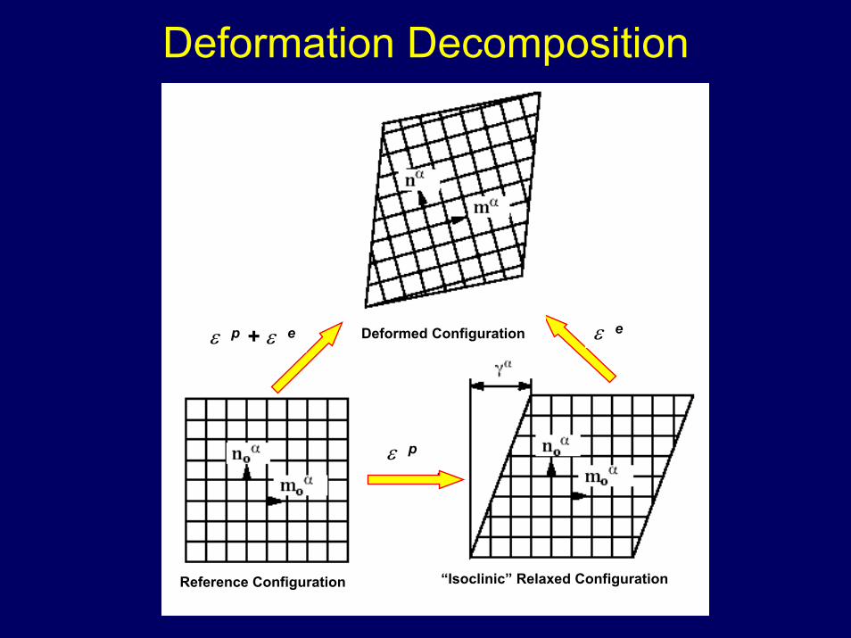
Deformation Decomposition
Reference Configuration “Isoclinic” Relaxed Configuration
ε p
ε eε p + ε e Deformed Configuration
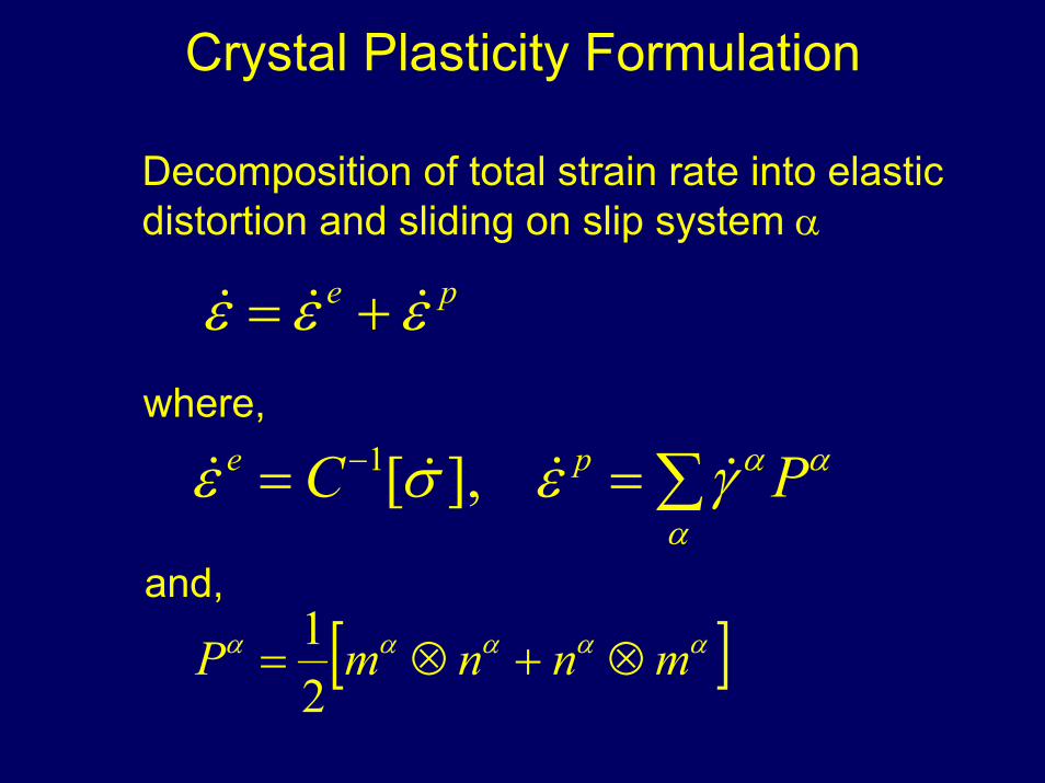
Crystal Plasticity Formulation
Decomposition of total strain rate into elastic distortion and sliding on slip system α
pe εεε &&& +=where,
∑== −
α
ααγεσε PC pe &&&& ],[1
and,
[ ]ααααα mnnmP ⊗+⊗=21
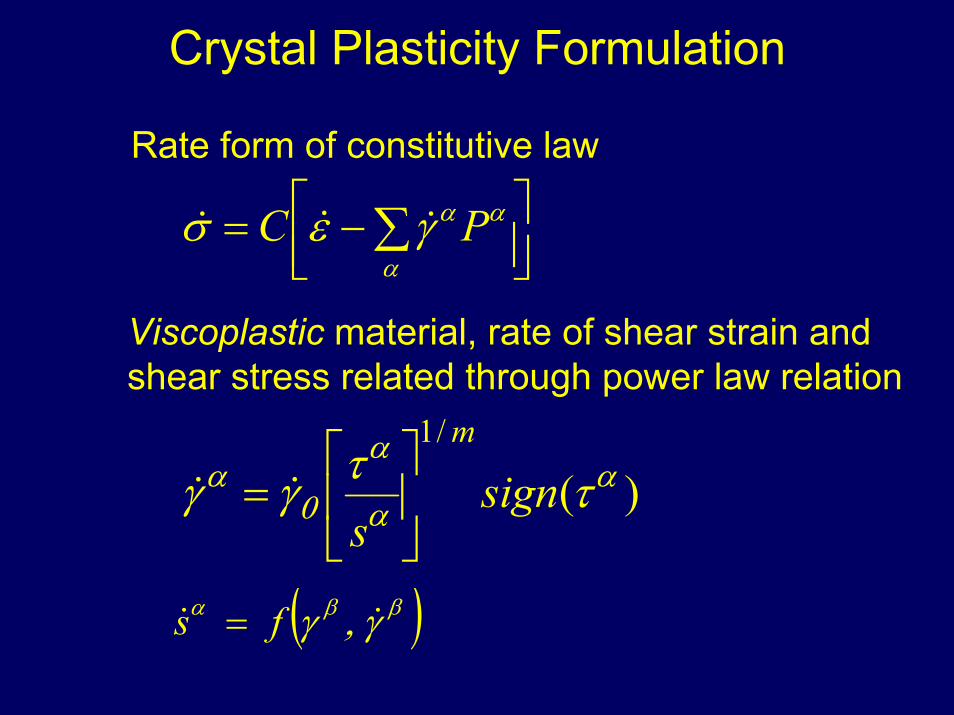
Crystal Plasticity Formulation
Rate form of constitutive law
−= ∑
α
ααγεσ PC &&&
Viscoplastic material, rate of shear strain and shear stress related through power law relation
)(/1
αα
α
0α ττγγ sign
s
m
= &&
( )ββα γ,γ && fs =
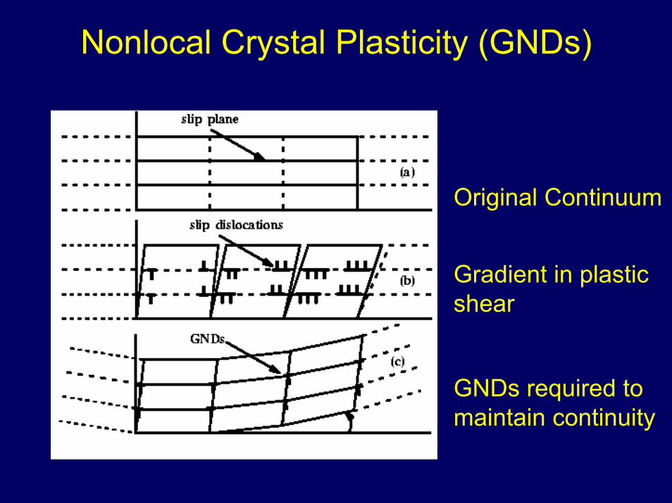
Nonlocal Crystal Plasticity (GNDs)
Original Continuum
Gradient in plastic shear
GNDs required to maintain continuity
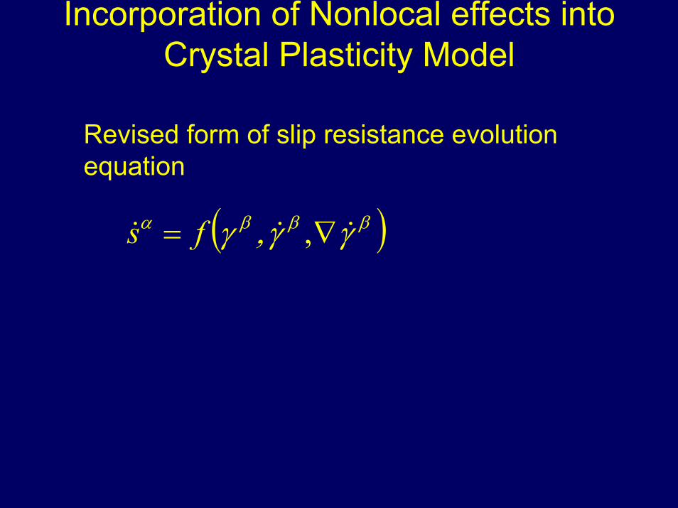
Incorporation of Nonlocal effects into Crystal Plasticity Model
Revised form of slip resistance evolution equation
( )βββα γγ,γ &&& ∇= ,fs
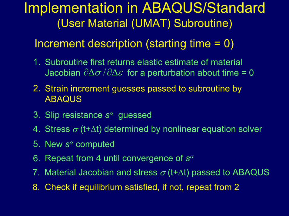
Implementation in ABAQUS/Standard(User Material (UMAT) Subroutine)
Increment description (starting time = 0)1. Subroutine first returns elastic estimate of material
Jacobian for a perturbation about time = 0εσ ∆∂∆∂ /2. Strain increment guesses passed to subroutine by
ABAQUS
3. Slip resistance sα guessedStress σ (t+∆t) determined by nonlinear equation solver4.
5. New sα computedRepeat from 4 until convergence of sα6.Material Jacobian and stress σ (t+∆t) passed to ABAQUS7.
8. Check if equilibrium satisfied, if not, repeat from 2
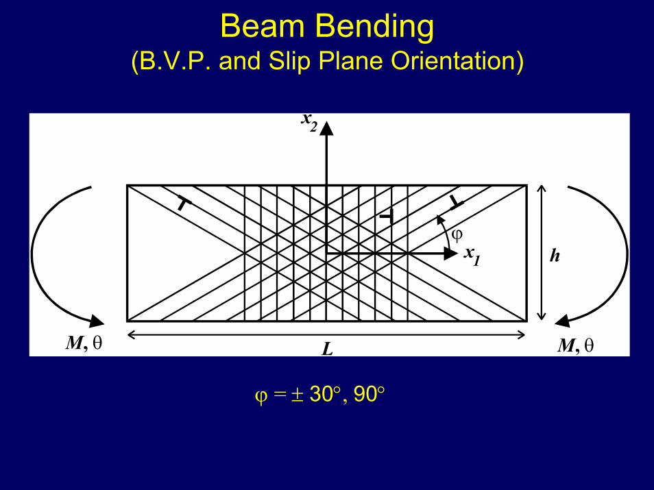
Beam Bending(B.V.P. and Slip Plane Orientation)
M, θ M, θL
x2
x1ϕ
h
ϕ = ± 30°, 90°
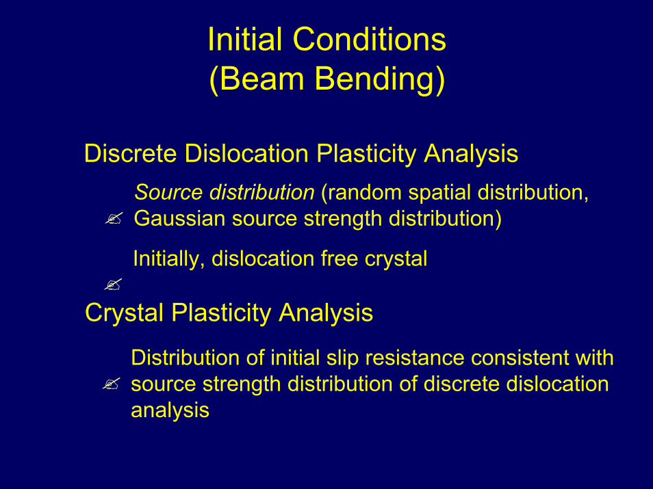
Initial Conditions(Beam Bending)
Discrete Dislocation Plasticity AnalysisSource distribution (random spatial distribution, Gaussian source strength distribution)
Initially, dislocation free crystal
Crystal Plasticity Analysis
Distribution of initial slip resistance consistent with source strength distribution of discrete dislocation analysis
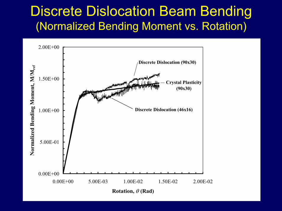
Discrete Dislocation Beam Bending(Normalized Bending Moment vs. Rotation)
0.00E+00
5.00E-01
1.00E+00
1.50E+00
2.00E+00
0.00E+00 5.00E-03 1.00E-02 1.50E-02 2.00E-02
Rotation, θ (Rad)
Nor
mal
ized
Ben
ding
Mom
ent,
M/M
ref
Discrete Dislocation (46x16)
Discrete Dislocation (90x30)
Crystal Plasticity(90x30)
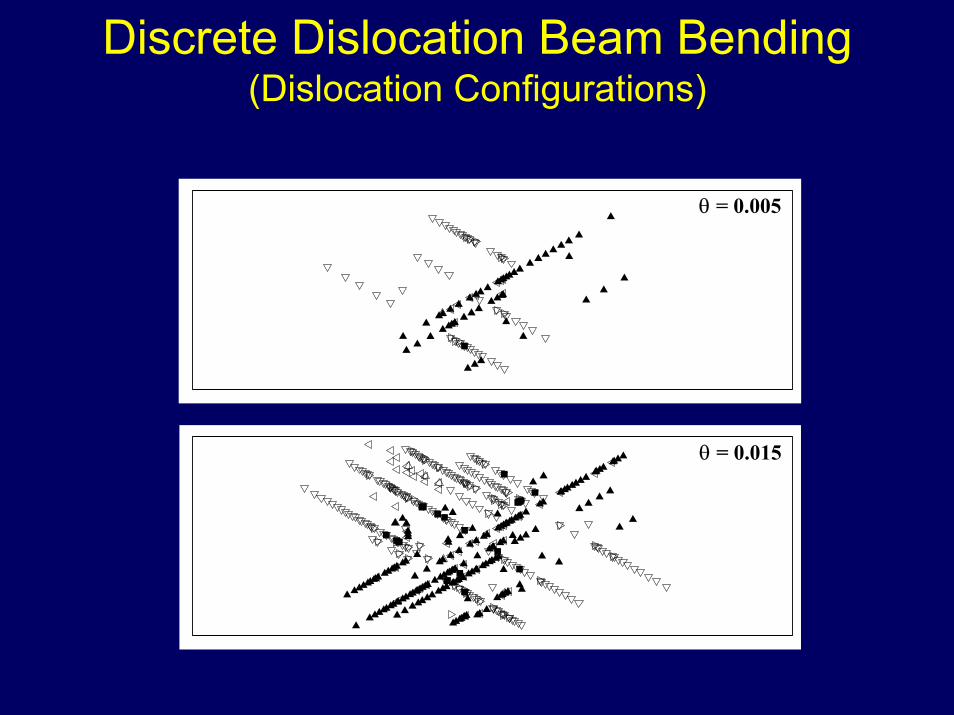
Discrete Dislocation Beam Bending(Dislocation Configurations)
θ = 0.005
θ = 0.015
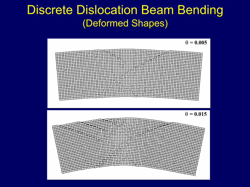
Discrete Dislocation Beam Bending(Deformed Shapes)
θ = 0.005
θ = 0.015
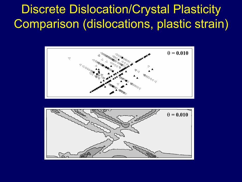
Discrete Dislocation/Crystal Plasticity Comparison (dislocations, plastic strain)
θ = 0.010
θ = 0.010
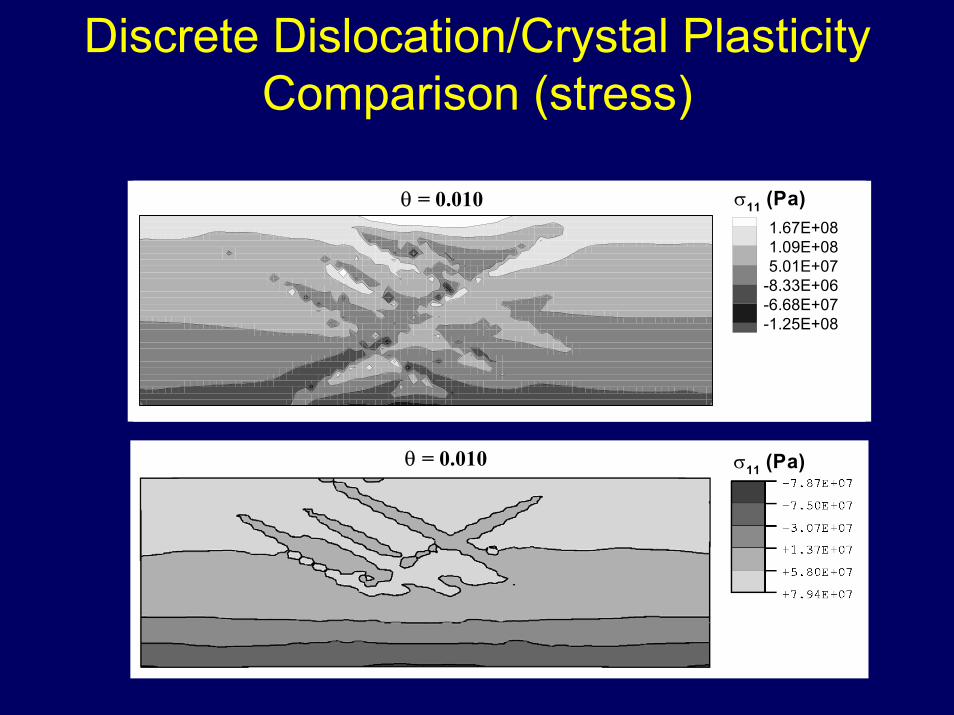
Discrete Dislocation/Crystal Plasticity Comparison (stress)
1.67E+081.09E+085.01E+07
-8.33E+06-6.68E+07-1.25E+08
σ11 (Pa)θ = 0.0101.67E+081.09E+085.01E+07
-8.33E+06-6.68E+07-1.25E+08
σ11 (Pa)θ = 0.010
σ11 (Pa)θ = 0.010
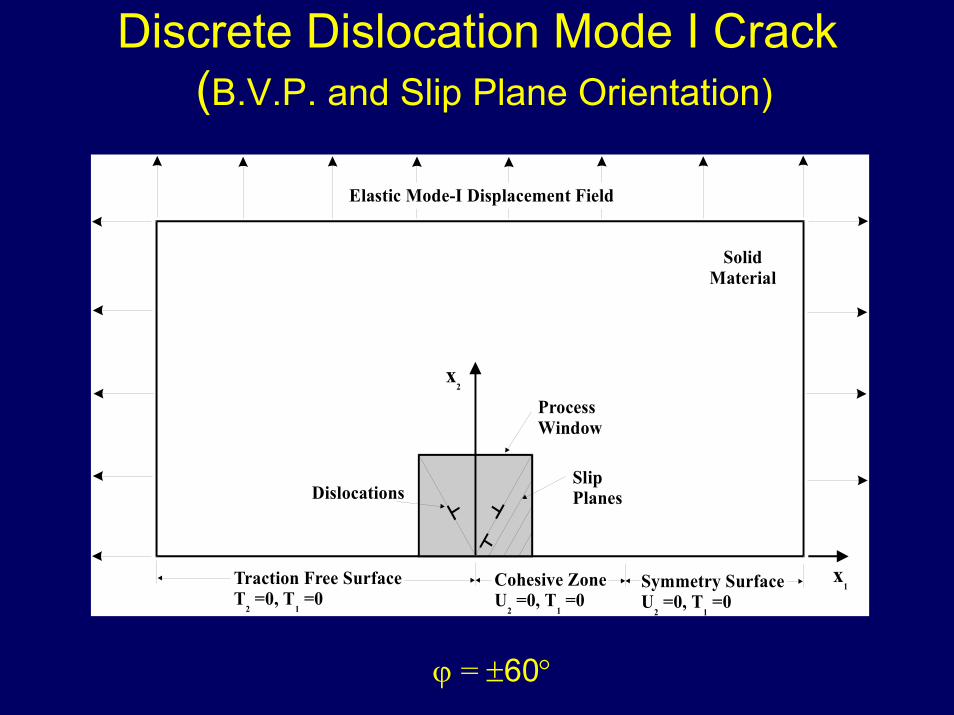
Discrete Dislocation Mode I Crack(B.V.P. and Slip Plane Orientation)
x2
ProcessWindow
SolidMaterial
DislocationsSlipPlanes
Traction Free SurfaceT =0, T =0
2 1
Cohesive ZoneU
2=0, T =0
1
Symmetry SurfaceU
2=0, T =0
1
x1
Elastic Mode-I Displacement Field
ϕ = ±60°
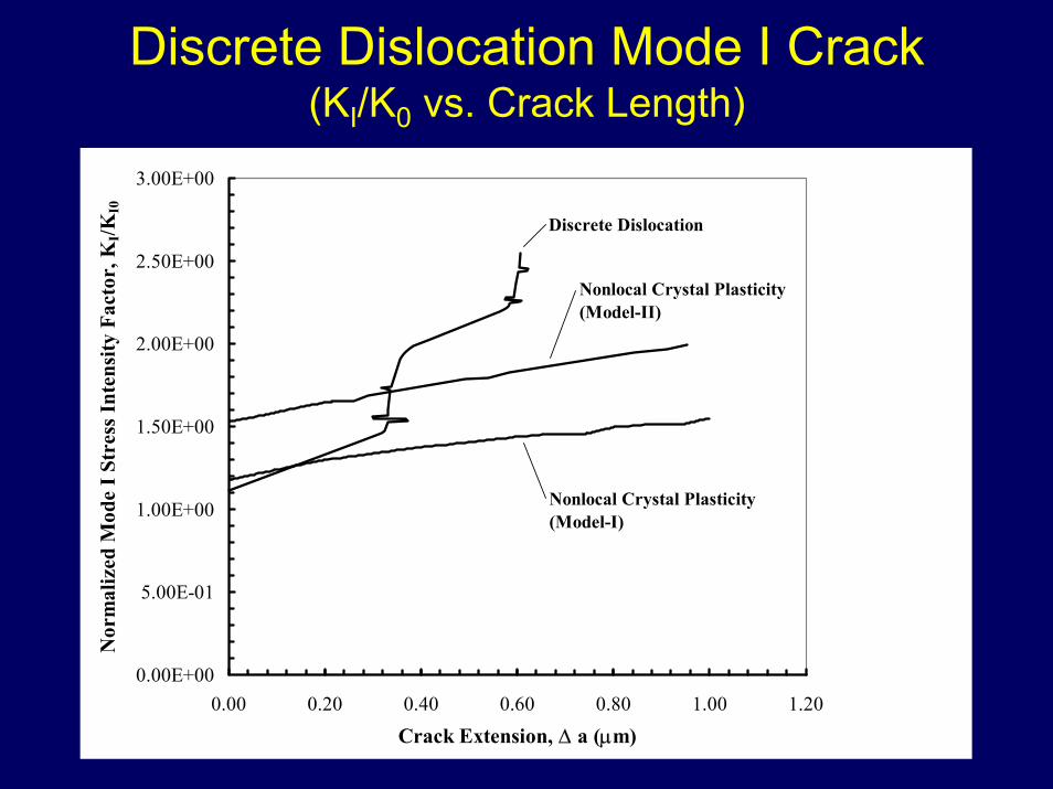
Discrete Dislocation Mode I Crack (KI/K0 vs. Crack Length)
0.00E+00
5.00E-01
1.00E+00
1.50E+00
2.00E+00
2.50E+00
3.00E+00
0.00 0.20 0.40 0.60 0.80 1.00 1.20
Crack Extension, ∆ a (µm)
Nor
mal
ized
Mod
e I S
tres
s Int
ensi
ty F
acto
r, K
I/KI0
Discrete Dislocation
Nonlocal Crystal Plasticity (Model-II)
Nonlocal Crystal Plasticity (Model-I)
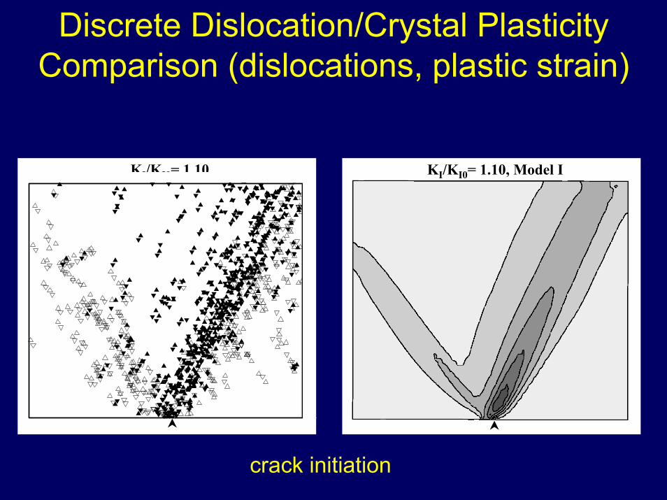
Discrete Dislocation/Crystal Plasticity Comparison (dislocations, plastic strain)
KI/KI0= 1.10 KI/KI0= 1.10, Model I
crack initiation
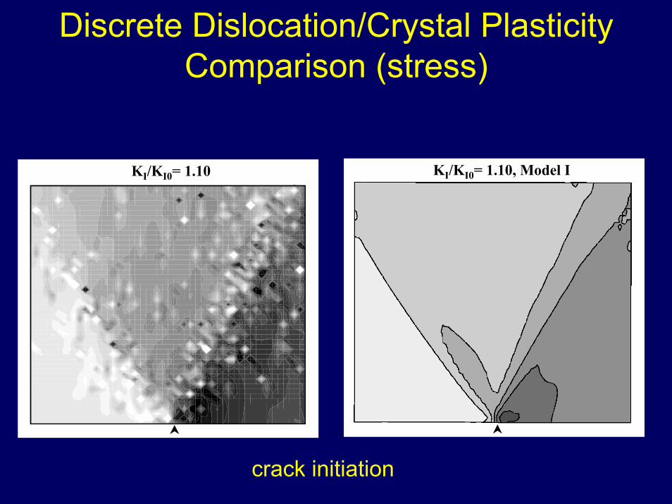
Discrete Dislocation/Crystal Plasticity Comparison (stress)
KI/KI0= 1.10, Model IKI/KI0= 1.10
crack initiation
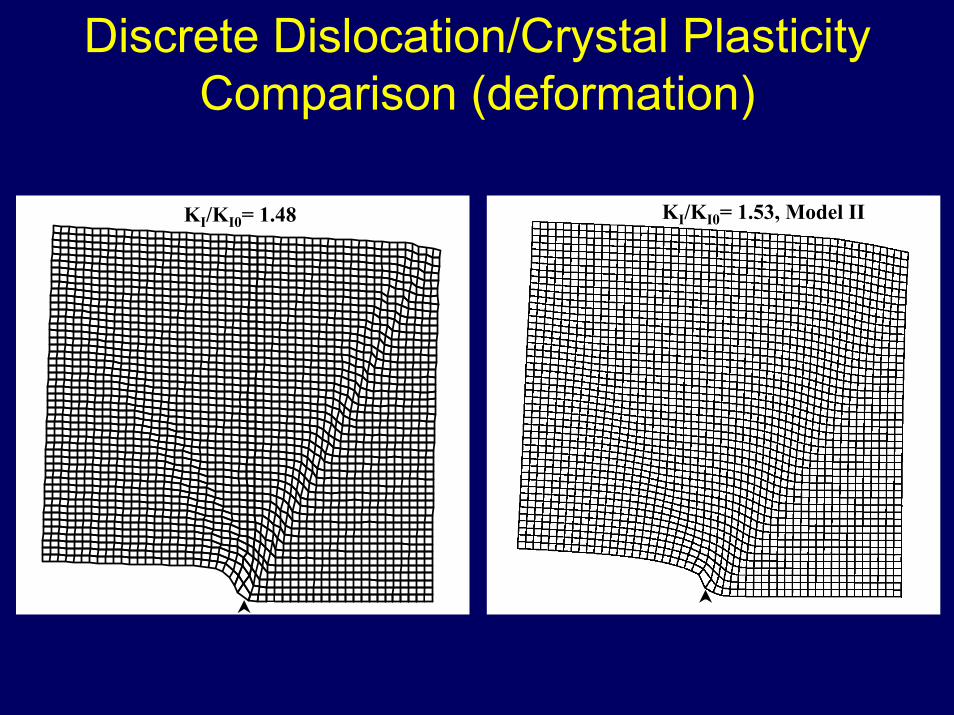
Discrete Dislocation/Crystal Plasticity Comparison (deformation)
KI/KI0= 1.48 KI/KI0= 1.53, Model II
ConclusionsMicro-beam bending and mode I crack problems in the presence of crystallographic slip were analyzed in a consistent manner using both discrete dislocation and crystal plasticity models.
Comparison of the results of the micro-beam bending analyses indicates a similarity in the global responses (bending moment vs. rotation) and some similarities in the plastic deformation patterning, but differences in the amount of deformation band formation and maximum axial stress.
Comparison of the results of the mode I crack analyses indicates an inability to simulate the global response (applied loading vs. crack extension) but qualitative and quantitative similarities exist in the deformation and stress fields and the crack profiles.