Embed Size (px)
Citation preview

Abstract
For Presentation at The University of Alabama in Huntsville
October 17, 2008
A Brief Introduction to the Theory of Friction Stir Welding
By Arthur C. Nunes, ]r Marshall Space Flight Center
Materials and Processes Laboratory, EM30 Huntsville, AL 35812
Friction stir welding CFSW) is a solid state welding process invented in 1991 at The Welding Institute in the United Kingdom. A weld is made in the FSW process by translating a rotating pin along a weld seam so as to stir the sides of the seam together. FSW avoids deleterious effects inherent in melting and is already an important welding process for the aerospace industry, where welds of optimal quality are demanded. The structure of welds determines weld properties. The structure of friction stir welds is determined by the flow field in the weld metal in the vicinity of the weld tool. A simple kinematic model of the FSW flow field developed at Marshall Space Flight Center, which enables the basic features of FSW microstructure to be understood and related to weld process parameters and tool design, is explained.
https://ntrs.nasa.gov/search.jsp?R=20110006308 2018-08-28T18:57:25+00:00Z

l _____ _
------- --- - -.----.~----------- .. --. - -- ------ ----- --- -.------ .~--- ---.-.. -----~ ---. -- -_."---- ----- - !
A Brief Introduction to the Theory of
Friction Stir Welding Arthur C. Nunes, Jr.
Metals Engineering Branch
Marshall Space Flight Center

I I
I I
I I
; I I I I
I I -
I
::::l
I
I r+
~
I I 0 c..
. !
I C
I
n r+
I -.
I
0 ::::l
I
1 \ 1-

1- - ~~~ -~--- - -~ - --~ - --~ - --- -- - - ---I I
Friction stir welding • Is a solid-state seam welding process. Melting does not normally
occur. Welding occurs automatically upon placing clean metal in contact.
• Was invented in 1991 at The Welding Institute, Cambridge, England (GB Patent Application No. 9125978.8, 6 December 1991).
• Avoids melting problems inherent in fusion welding: loss of strengthening structure in residual cast weld metal component; disturbance of dispersed strengthening phases (MMCs); safety issues (heat sources, spatter, molten metal); precision issues (wide fusion penetration variation due to Marangoni circulations); contamination issues (metal vapor may coat optics); etc.
L- __ ~~ _ _ __ _ -- - - -- - -- -- -- -- -- -- - - --- - - - -- - - - --- - - -- -- --- - - - - - ----

Basic friction stir welding configuration Longitudinal section courtesy of r.e. McClurefUniversity of Texas at El Paso
l

------- --- -
Plan view mid-sectional macrostructure of FSW in 0.317 inch thick 2219-T87 aluminum alloy plate. The pin-tool has been removed and replaced with bubble-filled mounting medium. Rotation is in the counterclockwise direction. The spindle speed was 220 RPM and the travel speed 3.5 inches per minute.

~~~--. - ----- ~~--.-
Shear surface, rotating plug model, and wiping transfer mechanism
• Shear occurs at a "discontinuity" in velocity between a plug of metal attached to the pin-tool and the weld metal bulk.
• The forward part of the moving shear surface picks up weld metal, which is rotated (wiped) around the tool in the rotating plug, and left behind as the tool moves on.
- - -.----~~- .. - --~~~ - .-~~- - --

- OJ ::l
OJ ..... " - o ~
-0
OJ
r+
r+
ro
.....
::l
Vl
--------
----------

Mathematical implementation of rotating plug model
ur
v r
- ------,.
• •
V ~
• •
Velocity field of metal in rotating plug (relative to pin;tool) is taken to be a superposition of two fields: 1) rotating cylinder and 2) uniform translation .
r dr r d8 r r . r v = - ur + r - ue = (v r - V cos8)u r + (reo + V sm8)ue dt dt
Trajectory of weld metal element inside plug is then:
v 1 r -cos8
dr = rI V d8 rw . 8 - +sm V
If v r « V and rw » V ,
dr "" _ V dsin8 w
In this case the maximum depth is & max "" - 2V on the retreating edge. If the shear w
surface radius is constant, there is no lateral (y) displacement at exit from the tool.

I I
L
e
d r/./4W/-/I,I /
c
b r/~.
a l ~ , ,
" '"
e
d
c
b
" V~ I a "
Two-dimensional planar "wiping" flow streamlines for a FSW flow field . The width of the pattern has been greatly exaggerated to reveal the structure more clearly. In the typical FSW case the flow around the tool takes place within a thin sliver of rotating metal just beneath the shear surface

----. -- - ------
i f
Shear surface
~ 0.008"
Recrystallized weld metal (N ote banding)
Retreating edge
Weld metal backflow
~.. Parent metal
Advancing edge
V [3.5in/min] 2- = 2 ::::.:: 0.005"
Q [2nrad I rev ][ 220rev I min]

Transverse Marker Longitudinal
Marker
Bimetallic Weld
PLANAR MARKER PATTERNS DUE TO TRANSLATING, ROTATING FIELD
----_._-- -- - - --


, -
,

l/)
I
r-+
I
~
OJ --
I
::J
, I :::u
\
OJ
,
I
r-+
I
ro
(J)
I I I \ I I I I I I
I I

RQ L\t
o Shear Zone
Shear strain rate in friction stir welding is comparable to that of metal cutting (103 to 105 sec-I).
(RQL\t) [0.19inches J[2n rad . 220RPM . _1 min] ~
dy = L\y = 0 = RQ ~ rev 60 sec ~ 0.8xl04 sec-I dt L\t (M) 0 [O.0005inchesJ

Comparison of friction stir welding and metal cutting
Flow Trajectory
Friction Stir Welding
Shear Interface

I
Low-cost manufacturing process for nanostructured metals and alloys
Travis L. Brown, Srinivasan Swaminathan, Srinivasan Chandrasekar, w. Dale Compton, Alexander H. King, and Kevin P. Trumble Schools of Engineering, Purdue University, West Lafayette, Indiana 47907-1287
Journal of Materials Research 17 (10) (2002). 2484-2482
In spite of their interesting properties, nanostructured materials have found limited uses because of the cost of preparation and the limited range of materials that can be synthesized. It has been shown that most of these limitations can be overcome by subjecting a material to large-scale deformation, as occurs during common machining operations. The chips produced during lathe machining of a variety of pure metals, steels, and other alloys are shown to be nanostructured with grain (crystal) sizes between 100 and 800 nm. The hardness of the chips is found to be significantly greater than that of the bulk material.
Typical friction stir shear produced grains ~ 10,000 nm.


UT
S/M
ax
UT
S
0
0 0 ~ ~
---
--"
0 · -
N
• 0
• ·
-W
• 0 ·
-
--I
.+::.
• ::::,
0
• 3
· -
CD
U1
I'""'t
•
0 · -
0)
• 0
• ·
-
-....J
• 0 ·
-co
0 · -
to

1 __
Viscous vs . plastic flow models
• Plastic metal flow is less sensitive to strain rate. • Metals are subject to shear instabilities (inhomogeneities)
as denoted on processing maps.
Local rearrangement mechanism (viscous flow)
( E
1: "" l kTe kT \ . nvl1y t
k = Boltzmann's Constant T = Absolute temperature E = Activation energy of process l1y = Shear strain per unit activation n = Number of activation elements per unit volume v = Oscillation rate of activation element
Dislocation slip mechanism (plastic flow)
1: "" E _ kT In( nl1:v) v v 2y
k = Boltzmann's Constant T = Absolute temperature E = Activation energy of process v = Activation volume for process l1y = Shear strain per unit activation n = Number of activation elements per unit volume v = Oscillation rate of activation element

A.P. Reynolds and Wei Tang, " Alloy, Tool Geometry, and Process Parameter Effects on Friction Stir Weld Energies and Resultant FSW Joint Properties," Friction Stir Welding and Processing, ed. K.Y. Jata et ai. (Warrendale, PA: The Minerals, Metals & Materials Society, 2001) 15-23.
Tool Rs R L Configuration (mm) (mm) (mm)
1 12.5 5 8.1 2 12.5 4 8.1 3 12.5 6 8.1
FSW Pin-Tool
4 10.0 5 8.1 Shear Zone f---- Rs
5 15.0 5 8.1
3 {I h M = 2:rtR -c - + - + 3 R
(L~hr +(R ,~RrHR';RH(R,;Rn)
R
~ = 1 _ -=---_ =L
L [l+~(R s;R)l

L~_~
Table I. Effect of Friction Stir Welding Tool Configuration on Power Requirement. Percent error in the comouted value in oarenthesis next to com oared val Tool Power Requirement Configuration (watts)
240 RPMl1.3 mm/sec 240 RPM/2.4 mm/sec 390 RPMl3.3mm/sec 1: = 2.01 ksi* 1: = 2.18 ksi* 1: = 1.75 ksi*
Measured Computed Measured Computed Measured Computed
I 2060 1870 (-9%) 2230 2030 (-9%) 2790 2660 (-5%) 2 1950 1670 (- 14%) 2100 1840 (- 12%) 2790 2400 (- 14%) 3 2270 2050 (- 10%) 2390 2230 (-7%) 2860 2910 (+2%) 4 1110 11 80 (+6%) 1260 1280 (+2%) 2290 1670 (-27%) 5 23 10 29 10 (+26%) 2560 3160 (+23%) 3040 4130 (+36%)
--
* Chosen for optimal data fit.

--, I
-c
0 ~
ro ~
:::0 ro
..c
c --•
~
ro 3 ro
::J
r+
(J)

Fusion Welding
i ,...., Melting Temperature at Melt Pool Surface
Friction Stir Welding
,...., 0.8 Melting Temperatu re at Shear Surface
Heat Losses of Fusion Welds and Friction Stir Welds Are Similar
.. _-'

-. (f)
..0
.....J +-' u..
......... (1J :l C" ~
0 l-
I
l~ __ ~
1 5 , ,
•
• I • •
J • •
o , , o 1000 2000
RPM
3000
Courtesy of R. CarteriMSFC Metals Engineering Branch
4000

--I
I ::
r I
ro
I I
--I
::r -- .,
I
c..
0 -- 3 I
ro
:::J
, I (J
) --I I
0 :::J
I I

1_
Minimization of torque (assuming constant t)
() f Sheariog2nr2-r;,h + r2dz = 0 Surface
:. z = aF( (jl \ a) 'P = cos-,(: )
PIN
ISOTHERMAL SHEAR SURFACE FOR MINIMAL TORQUE
a = 45°
The computed shear sunace shape (solid line) yielding minimal torque/power for isothermal/constant flow stress FSW tool environment. F( cp/a) is an elliptic integral of the first kind. A simplified linear approximation (dashed line) is also shown.
--
Fragmentation
(T
Expanded - Radius
----
----- - - -~--- -
Scatter
--
-
Shear .... ~ Surface
Oscillation
+4-- Reduced Radius
-
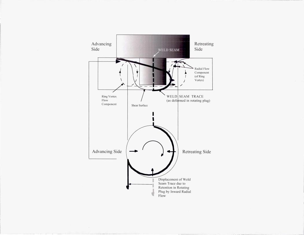
Advancing Side
Ring Vortex Flow Component
t (
Shear Surface
I I
)
Retreating Side
Radial Flow Component (of Ring Vortex)
SEAM TRACE (as def~rmed in rotating plug)
Advancing Side ~ Retreating Side
- - ------- - -------------------
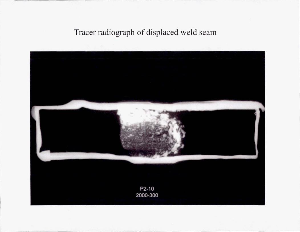
Displacement of Weld Seam Trace due to Retention in Rotating Plug by Inward Radial Flow
I
I
I

):>
<
o -.
c..
. -.

Defect causes
• Parameters (rpm, weld speed, plunge force): flash, trenches, surface fissures, wormholes
• Joint preparation (e.g. , seam cleanliness): residual oxide defect
• Tool design (e.g. , pin bottom-anvil clearance): lack of penetration
- ---- ----------

L __ _
---------------- ----- --- -
CONCLUSION:
Control friction stir welds using a kinematic model
• Weld structure controls weld properties. • Weld flow field controls weld structure. • Specific aspects of weld process parameters and
tool design control components of weld flow field (in kinematic model).
• We control weld process parameters and tool design.