Embed Size (px)
Citation preview
A 3D Morphable Model of Craniofacial Shape and Texture Variation
Hang Dai, Nick Pears and William Smith
Department of Computer Science, University of York, UK
{hd816,nick.pears,william.smith}@york.ac.uk
Christian Duncan
Alder Hey Hospital, Liverpool, UK
Abstract
We present a fully automatic pipeline to train 3D Mor-
phable Models (3DMMs), with contributions in pose nor-
malisation, dense correspondence using both shape and
texture information, and high quality, high resolution tex-
ture mapping. We propose a dense correspondence system,
combining a hierarchical parts-based template morphing
framework in the shape channel and a refining optical flow
in the texture channel. The texture map is generated us-
ing raw texture images from five views. We employ a pixel-
embedding method to maintain the texture map at the same
high resolution as the raw texture images, rather than us-
ing per-vertex color maps. The high quality texture map is
then used for statistical texture modelling. The Headspace
dataset used for training includes demographic information
about each subject, allowing for the construction of both
global 3DMMs and models tailored for specific gender and
age groups. We build both global craniofacial 3DMMs and
demographic sub-population 3DMMs from more than 1200
distinct identities. To our knowledge, we present the first
public 3DMM of the full human head in both shape and
texture: the Liverpool-York Head Model. Furthermore, we
analyse the 3DMMs in terms of a range of performance
metrics. Our evaluations reveal that the training pipeline
constructs state-of-the-art models.
1. Introduction
Morphable models of 3D shape have many applica-
tions in creative media, medical image analysis and biomet-
rics. Traditional model building pipelines have used man-
ual landmarking to initialise surface alignment. However,
this is extremely time-consuming and laborious for large-
scale datasets. Here we present a fully automatic approach
and apply it to a large dataset of 3D images of the human
head, thus generating the first public shape-and-texture 3D
morphable model (3DMM) of the full human head: the
Liverpool-York Head Model (LYHM).
A full head model opens up new opportunities not af-
forded by existing 3D face models [21]. For example: (i) we
can reconstruct the most likely full head shape from partial
data. This allows the modelling of different hair styles onto
a correctly proportioned cranium (cranial shape usually can-
not be directly observed). (ii) any part of the head shape can
be matched against population norms thus facilitating tools
for craniofacial diagnoses and surgical intervention evalu-
ation, and (iii) the ability to complete partial views of the
head may be exploited in biometric applications.
Contributions: (i) We propose a fully automatic
pipeline to build 3DMMs, with contributions in pose nor-
malisation and dense correspondence - in particular we pro-
pose a hierarchical parts-based template morphing frame-
work with optical flow correspondence refinement. (ii) We
propose a high quality texture map from several views of
cameras for the morphed template and use the texture map
for texture modelling. (iii) We build both global cranio-
facial 3DMMs and demographic sub-population 3DMMs
from more than 1200 distinct identities in the Headspace
dataset [1, 16] and we will make them publicly available1. Fig. 1 illustrates the principal components of the global
and child model. To our best knowledge, our models are
the first public shape-and-texture craniofacial 3DMMs of
the full human head. (iv) We demonstrate flexibility modes
of our model such that, when given a fixed face shape, we
compute the range of possible cranial shapes and vice-versa.
After discussing literature, we describe our dataset and
3DMM training pipeline, while the following sections
present details of the proposed methods. Section 8 provides
an extensive evaluation of the 3DMMs, and a final section
is used for conclusions.
2. Related work
In the late 1990s, Blanz and Vetter built a 3DMM from
3D face scans [7] and employed it in 2D face recogni-
tion [8]. Two hundred scans were used to build the model
(young adults, 100 males and 100 females). Dense corre-
spondences were computed using optical flow with an en-
ergy dependent on both shape and texture.
There are very few publicly available morphable models
1https://www-users.cs.york.ac.uk/˜nep/research/LYHM/
13085
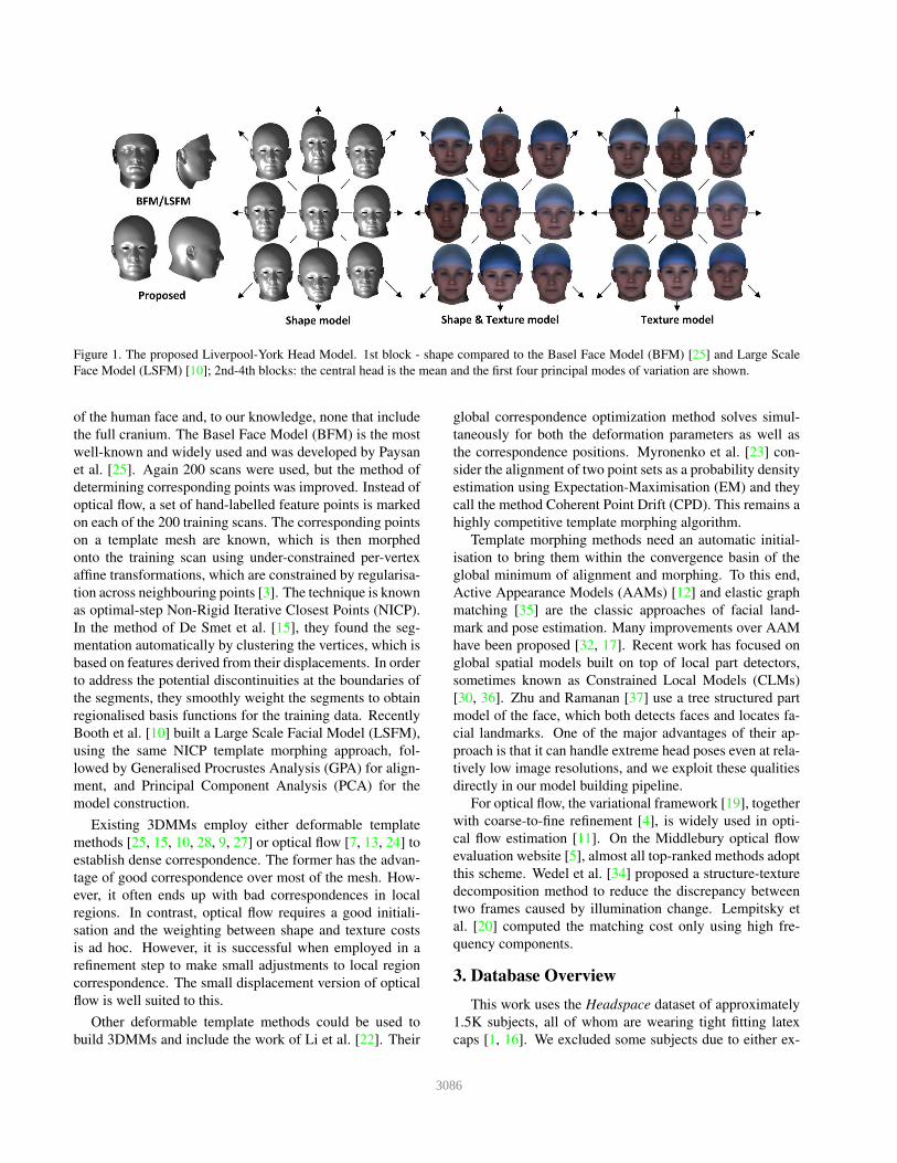
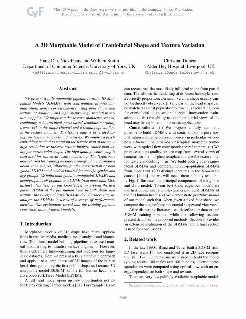
Figure 1. The proposed Liverpool-York Head Model. 1st block - shape compared to the Basel Face Model (BFM) [25] and Large Scale
Face Model (LSFM) [10]; 2nd-4th blocks: the central head is the mean and the first four principal modes of variation are shown.
of the human face and, to our knowledge, none that include
the full cranium. The Basel Face Model (BFM) is the most
well-known and widely used and was developed by Paysan
et al. [25]. Again 200 scans were used, but the method of
determining corresponding points was improved. Instead of
optical flow, a set of hand-labelled feature points is marked
on each of the 200 training scans. The corresponding points
on a template mesh are known, which is then morphed
onto the training scan using under-constrained per-vertex
affine transformations, which are constrained by regularisa-
tion across neighbouring points [3]. The technique is known
as optimal-step Non-Rigid Iterative Closest Points (NICP).
In the method of De Smet et al. [15], they found the seg-
mentation automatically by clustering the vertices, which is
based on features derived from their displacements. In order
to address the potential discontinuities at the boundaries of
the segments, they smoothly weight the segments to obtain
regionalised basis functions for the training data. Recently
Booth et al. [10] built a Large Scale Facial Model (LSFM),
using the same NICP template morphing approach, fol-
lowed by Generalised Procrustes Analysis (GPA) for align-
ment, and Principal Component Analysis (PCA) for the
model construction.
Existing 3DMMs employ either deformable template
methods [25, 15, 10, 28, 9, 27] or optical flow [7, 13, 24] to
establish dense correspondence. The former has the advan-
tage of good correspondence over most of the mesh. How-
ever, it often ends up with bad correspondences in local
regions. In contrast, optical flow requires a good initiali-
sation and the weighting between shape and texture costs
is ad hoc. However, it is successful when employed in a
refinement step to make small adjustments to local region
correspondence. The small displacement version of optical
flow is well suited to this.
Other deformable template methods could be used to
build 3DMMs and include the work of Li et al. [22]. Their
global correspondence optimization method solves simul-
taneously for both the deformation parameters as well as
the correspondence positions. Myronenko et al. [23] con-
sider the alignment of two point sets as a probability density
estimation using Expectation-Maximisation (EM) and they
call the method Coherent Point Drift (CPD). This remains a
highly competitive template morphing algorithm.
Template morphing methods need an automatic initial-
isation to bring them within the convergence basin of the
global minimum of alignment and morphing. To this end,
Active Appearance Models (AAMs) [12] and elastic graph
matching [35] are the classic approaches of facial land-
mark and pose estimation. Many improvements over AAM
have been proposed [32, 17]. Recent work has focused on
global spatial models built on top of local part detectors,
sometimes known as Constrained Local Models (CLMs)
[30, 36]. Zhu and Ramanan [37] use a tree structured part
model of the face, which both detects faces and locates fa-
cial landmarks. One of the major advantages of their ap-
proach is that it can handle extreme head poses even at rela-
tively low image resolutions, and we exploit these qualities
directly in our model building pipeline.
For optical flow, the variational framework [19], together
with coarse-to-fine refinement [4], is widely used in opti-
cal flow estimation [11]. On the Middlebury optical flow
evaluation website [5], almost all top-ranked methods adopt
this scheme. Wedel et al. [34] proposed a structure-texture
decomposition method to reduce the discrepancy between
two frames caused by illumination change. Lempitsky et
al. [20] computed the matching cost only using high fre-
quency components.
3. Database Overview
This work uses the Headspace dataset of approximately
1.5K subjects, all of whom are wearing tight fitting latex
caps [1, 16]. We excluded some subjects due to either ex-
3086
Figure 2. Age distribution of subjects
cessive hair bulge or declared craniofacial surgery/trauma
condition and employed around 1.2K subjects in the global
model build. A 3dMD five-camera system was employed,
creating a 3D triangular surface for each subject composed
of typically 180K vertices joined into typically 360K trian-
gles, along with a high-resolution texture image.
FRGC [26], MeIn3D [10] and FaceBase [29] are large
3D face datasets, but the full cranium is not included. In
contrast, the Size China project [6] does include the cra-
nium, but it is a commercial dataset and 3DMMs have not
been built. Our Headspace dataset is the only full head
dataset for academic use and will be made publicly avail-
able (both the trained models and raw data).
Subjects were imaged at Alder Hey Hospital, Liverpool,
and provided metadata including gender, age, ethnicity, eye
color, and any craniofacial surgery/trauma condition. This
information allows for the construction of models for tar-
geted populations, such as within a defined age range or
gender. The dataset covers a wide variety of age (see Fig.2),
and is balanced in gender.
4. Model construction
Our 3DMM training pipeline, illustrated in Fig.3, oper-
ates in three main functional blocks. These are outlined be-
low and detailed in the following three sections.
Data preprocessing: We use automatic 2D landmarking
and map to 3D using the known 2D-to-3D registration sup-
plied by the 3D camera system. These 3D landmarks can
then be used for pose normalisation.
Dense correspondence: A collection of 3D scans are
reparametrised into a form where each scan has the same
number of points joined into a triangulation that is shared
across all scans. Furthermore, the semantic or anatomical
meaning of each point is shared across the collection, as
defined by a template mesh.
Alignment and statistical modelling: The collection of
scans in dense correspondence are subjected to Generalised
Procrustes Analysis (GPA) to remove similarity effects (ro-
tation, translation, scale), leaving only shape information.
The processed meshes are statistically analysed, typically
with Principal Component Analysis (PCA), generating a
3DMM as a linear basis of shapes. This allows for the gen-
eration of novel shape instances.
5. Data preprocessing
Data preprocessing includes 2D landmarking, projection
to 3D landmarks and pose normalisation.
5.1. Automatic 2D/3D facial landmarking
We use the method of Zhu and Ramanan [37] to localise
facial landmarks on the texture channel of each 3D image.
This 2D image contains all 5 viewpoints of the capture sys-
tem and usually two face detections are found, 15-45 de-
grees yaw from frontal pose, corresponding to the left and
right side of the face. Detected 2D points are in a tree struc-
ture and are projected to 3D using OBJ texture coordinates.
5.2. Pose normalisation
Each face detection employs one of thirteen tree mod-
els [37] and we automatically learn how to orientate each of
these to frontal pose, based on their 3D structure. To do this,
we apply GPA to each collection of 3D trees (11 of the 13
models are used by the dataset) and find the nearest-to-mean
tree shape in a scale-normalised setting. We then apply a 3D
face landmarker [14] to the 3D data of the nearest-to-mean
tree shape (11 of these), which generates a set of 14 land-
marks with clear semantic meaning. Finally, we find the
alignment that moves the symmetry plane of these 14 land-
marks to the Y-Z plane with the nasion above the subnasale
(larger Y coordinate) and at the same Z-coordinate, in order
to normalise the tilt (X rotation). To complete the training
phase, the mean 3D tree points for each of the 13 trees are
then carried into this canonical frontal pose using the same
rotation, and are used as reference points for the frontal pose
normalisation of the 3D trees.
In around 1% of the dataset, only one tree is detected and
that is used for pose normalisation, and in the rest 2-3 im-
ages are detected. In the cases where 3 trees are detected,
the lowest scoring tree is always false positive and can be
discarded. For the remaining two trees, a weighted combi-
nation of the two rotations is computed using quaternions,
where the weighting is based on the mean Euclidean error
to the mean tree, in the appropriate tree component.
6. Dense correspondence
In this section, we propose a new template morphing
framework along with optical flow correspondence refine-
ment. Both shape information and texture information are
used for correspondence establishment.
3087
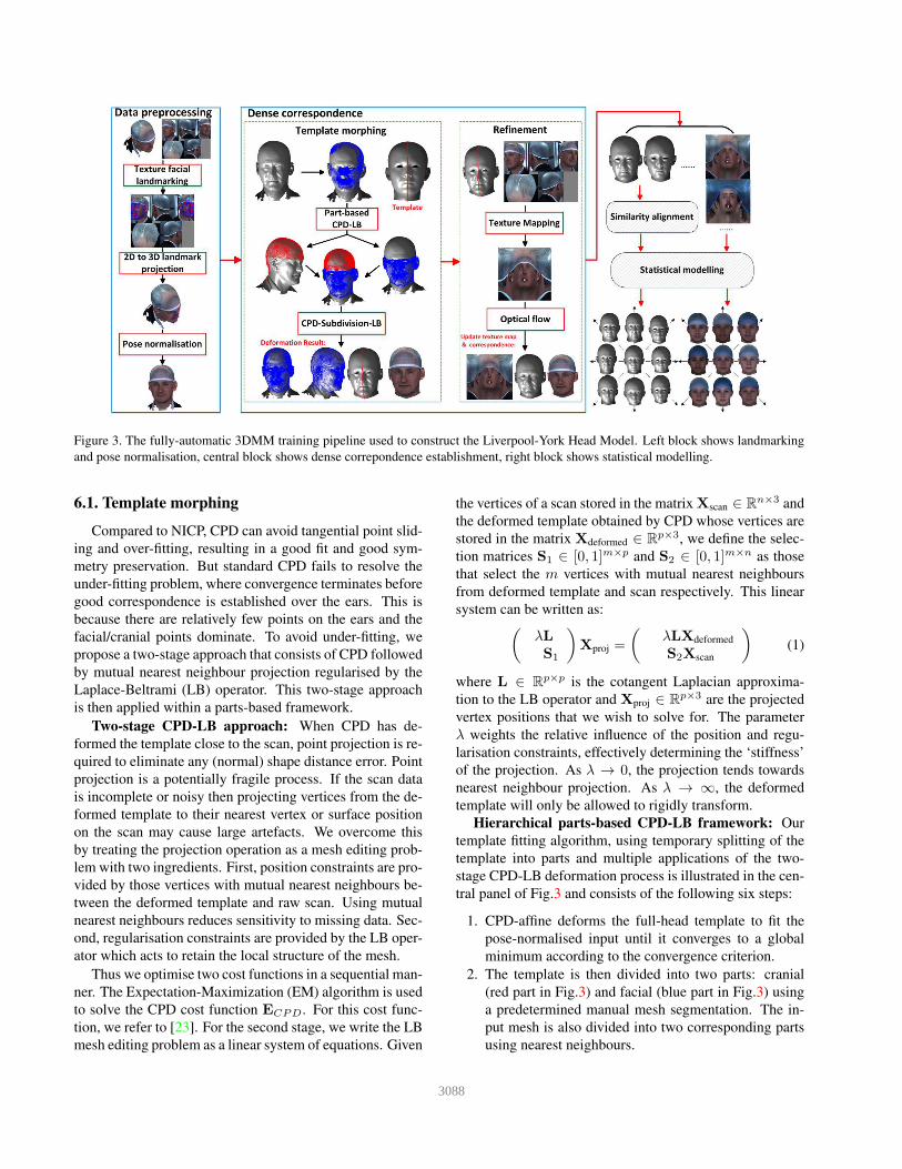
Figure 3. The fully-automatic 3DMM training pipeline used to construct the Liverpool-York Head Model. Left block shows landmarking
and pose normalisation, central block shows dense correpondence establishment, right block shows statistical modelling.
6.1. Template morphing
Compared to NICP, CPD can avoid tangential point slid-
ing and over-fitting, resulting in a good fit and good sym-
metry preservation. But standard CPD fails to resolve the
under-fitting problem, where convergence terminates before
good correspondence is established over the ears. This is
because there are relatively few points on the ears and the
facial/cranial points dominate. To avoid under-fitting, we
propose a two-stage approach that consists of CPD followed
by mutual nearest neighbour projection regularised by the
Laplace-Beltrami (LB) operator. This two-stage approach
is then applied within a parts-based framework.
Two-stage CPD-LB approach: When CPD has de-
formed the template close to the scan, point projection is re-
quired to eliminate any (normal) shape distance error. Point
projection is a potentially fragile process. If the scan data
is incomplete or noisy then projecting vertices from the de-
formed template to their nearest vertex or surface position
on the scan may cause large artefacts. We overcome this
by treating the projection operation as a mesh editing prob-
lem with two ingredients. First, position constraints are pro-
vided by those vertices with mutual nearest neighbours be-
tween the deformed template and raw scan. Using mutual
nearest neighbours reduces sensitivity to missing data. Sec-
ond, regularisation constraints are provided by the LB oper-
ator which acts to retain the local structure of the mesh.
Thus we optimise two cost functions in a sequential man-
ner. The Expectation-Maximization (EM) algorithm is used
to solve the CPD cost function ECPD. For this cost func-
tion, we refer to [23]. For the second stage, we write the LB
mesh editing problem as a linear system of equations. Given
the vertices of a scan stored in the matrix Xscan ∈ Rn×3 and
the deformed template obtained by CPD whose vertices are
stored in the matrix Xdeformed ∈ Rp×3, we define the selec-
tion matrices S1 ∈ [0, 1]m×p and S2 ∈ [0, 1]m×n as those
that select the m vertices with mutual nearest neighbours
from deformed template and scan respectively. This linear
system can be written as:(
λL
S1
)
Xproj =
(
λLXdeformed
S2Xscan
)
(1)
where L ∈ Rp×p is the cotangent Laplacian approxima-
tion to the LB operator and Xproj ∈ Rp×3 are the projected
vertex positions that we wish to solve for. The parameter
λ weights the relative influence of the position and regu-
larisation constraints, effectively determining the ‘stiffness’
of the projection. As λ → 0, the projection tends towards
nearest neighbour projection. As λ → ∞, the deformed
template will only be allowed to rigidly transform.
Hierarchical parts-based CPD-LB framework: Our
template fitting algorithm, using temporary splitting of the
template into parts and multiple applications of the two-
stage CPD-LB deformation process is illustrated in the cen-
tral panel of Fig.3 and consists of the following six steps:
1. CPD-affine deforms the full-head template to fit the
pose-normalised input until it converges to a global
minimum according to the convergence criterion.
2. The template is then divided into two parts: cranial
(red part in Fig.3) and facial (blue part in Fig.3) using
a predetermined manual mesh segmentation. The in-
put mesh is also divided into two corresponding parts
using nearest neighbours.
3088
3. The segmentation in step 2 releases the two individ-
ual parts from the global minimum in step 1 and CPD
affine continues on the two parts separately to re-
establish convergence. In practice, the cranial part is
already very close to its global minimum, but the facial
part continues to deform over many more iterations.
4. After convergence, the two parts of the template are
updated using LB-regularised projection; however,
there may exist a gap or an overlap between the two
parts, due to the separate deformation processes.
5. The deformed full template from step 1 is now used
to deform towards the two deformed parts-based tem-
plates from the previous step. Note that we now have
a known one-to-one correspondence between the full
template and the two template parts. Under these cir-
cumstances CPD-nonrigid performs well and is used.
6. After CPD-nonrigid converges, a final stage of LB-
regularised projection is used to give the final morphed
template of the full head, which is devoid of any over-
laps or discontinuities that appear between the two sep-
arate parts in step 4 and is superior to the initial defor-
mation from step 1 (standard CPD-affine).
7. Morphed template mesh subdivision followed by LB-
regularised projection is used to upscale resolution.
6.2. Texture map
It is preferable to store texture information in a UV space
texture map where resolution is unconstrained rather than
store only per-vertex colours where resolution is limited by
mesh resolution. To do so requires the texture information
from each scan to be transformed into a standard UV texture
space for which the embedding of the template is known.
After template morphing, the deformed template has
the same number of points joined into a triangulation that
is shared across all scans. Thus in UV coordinates, UV
faces of the morphed template are shared with the template.
Given the morphed vertex positions Xmorphed ∈ Rp×3 from
template morphing stage, we can first compute the UV co-
ordinates for each point of the morphed template in original
texture image:
[u,v] = g(S3Xscan) (2)
where S3 ∈ Rp×n is the selection matrix that select the
p vertices with nearest neighbours from morphed template
Xmorphed to the scan Xscan and g is the UV coordinates map-
ping from the raw mesh to texture image. The UV coordi-
nates mapping from texture image to raw mesh is a surjec-
tion but not an injection. Thus the points from the raw mesh
may have several sets of UV coordinates [u,v]cand in the
texture image, depending on the number of capture view-
points. To overcome this, we minimise the face area of UV
face UVkfaces to find the exact UV coordinates:
[u∗
i ,v∗
i ] = argminui,vi
h([ui,vi], [uj1,vj1], [uj2,vj2]) (3)
where [ui,vi] ∈ [u,v]cand, [uj1,vj1] and [uj2,vj2] ∈
UVkface, and h is the face area computation.
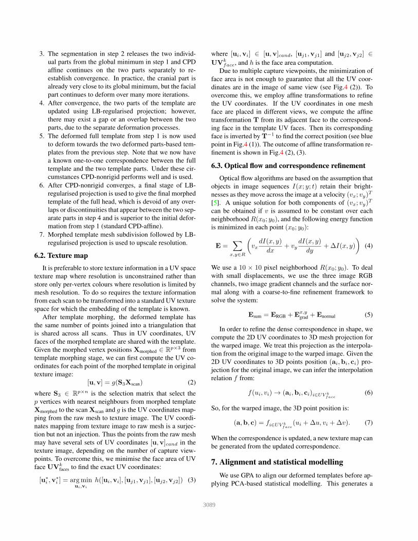
Due to multiple capture viewpoints, the minimization of
face area is not enough to guarantee that all the UV coor-
dinates are in the image of same view (see Fig.4 (2)). To
overcome this, we employ affine transformations to refine
the UV coordinates. If the UV coordinates in one mesh
face are placed in different views, we compute the affine
transformation T from its adjacent face to the correspond-
ing face in the template UV faces. Then its corresponding
face is inverted by T−1 to find the correct position (see blue
point in Fig.4 (1)). The outcome of affine transformation re-
finement is shown in Fig.4 (2), (3).
6.3. Optical flow and correspondence refinement
Optical flow algorithms are based on the assumption that
objects in image sequences I(x; y; t) retain their bright-
nesses as they move across the image at a velocity (vx; vy)T
[5]. A unique solution for both components of (vx; vy)T
can be obtained if v is assumed to be constant over each
neighborhood R(x0; y0), and the following energy function
is minimized in each point (x0; y0):
E =∑
x,y∈R
(
vxdI(x, y)
dx+ vy
dI(x, y)
dy+∆I(x, y)
)
(4)
We use a 10 × 10 pixel neighborhood R(x0; y0). To deal
with small displacements, we use the three image RGB
channels, two image gradient channels and the surface nor-
mal along with a coarse-to-fine refinement framework to
solve the system:
Esum = ERGB +Ex,ygrad +Enormal (5)
In order to refine the dense correspondence in shape, we
compute the 2D UV coordinates to 3D mesh projection for
the warped image. We treat this projection as the interpola-
tion from the original image to the warped image. Given the
2D UV coordinates to 3D points position (ai,bi, ci) pro-
jection for the original image, we can infer the interpolation
relation f from:
f(ui, vi) → (ai,bi, ci)i∈UV kface
(6)
So, for the warped image, the 3D point position is:
(a,b, c) = fi∈UV kface
(ui +∆u, vi +∆v). (7)
When the correspondence is updated, a new texture map can
be generated from the updated correspondence.
7. Alignment and statistical modelling
We use GPA to align our deformed templates before ap-
plying PCA-based statistical modelling. This generates a
3089
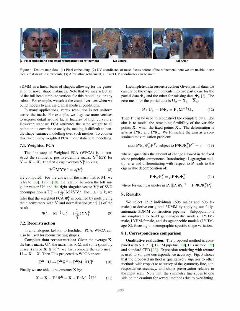
Figure 4. Texture map flow: (1) Pixel embedding, (2) UV coordinates of mesh facets before affine refinement, here we are unable to use
facets that straddle viewpoints, (3) After affine refinement, all facet UV coordinates can be used.
3DMM as a linear basis of shapes, allowing for the gener-
ation of novel shape instances. Note that we may select all
of the full head template vertices for this modelling, or any
subset. For example, we select the cranial vertices when we
build models to analyse cranial medical conditions.
In many applications, vertex resolution is not uniform
across the mesh. For example, we may use more vertices
to express detail around facial features of high curvature.
However, standard PCA attributes the same weight to all
points in its covariance analysis, making it difficult to han-
dle shape variance modelling over such meshes. To counter
this, we employ weighted PCA in our statistical modelling.
7.1. Weighted PCA
The first step of Weighted PCA (WPCA) is to con-
struct the symmetric positive-definite matrix YTMY for
Y = X−X. The first k eigenvectors Vk
isolving
YTMYV
k
i= λiV
k
i(8)
are computed. For the entries of the mass matrix M, we
refer to [33]. From [18], the relation between the left sin-
gular vector Uk
iand the right singular vector Vk
iof SVD
decomposition is Uk
i= ( 1
σk
i
)M1
2YVk
i. For 1 ≤ i ≤ k, we
infer that the weighted PCA Ψk
iis obtained by multiplying
the eigenvectors with Y and normalisation(w.r.t‖.‖) of the
result:
Ψk
i= M
−1
2Uk
i= (
1
σk
i
)YVk
i(9)
7.2. Reconstruction
In an analogous fashion to Euclidean PCA, WPCA can
also be used for reconstructing shapes.
Complete data reconstruction: Given the average X,
the basis matrix Uk
i, the mass matrix M and some (possibly
unseen) shape X ∈ R3n, we first compute the zero mean
U = X−X. Then U is projected to WPCA space:
Pk : U → P
kΨ
k = PkM
−1
2Uk
i(10)
Finally we are able to reconstruct X by:
X = X+PkΨ
k = X+PkM
−1
2Uk
i(11)
Incomplete data reconstruction: Given partial data, we
can divide the shape components into two parts: one for the
partial data Ψa and the other for missing data Ψb [2]. The
zero mean for the partial data is Ua = Xa −Xa:
P : Ua → PΨa = PaM−
1
2Ua (12)
Then P can be used to reconstruct the complete data. The
aim is to model the remaining flexibility of the variable
points Xa when the fixed points Xb. The deformation is
give as PΨa and PΨb. We formulate the aim as a con-
strained maximization problem:
maxPΨaΨTaP
T , subject to PΨbΨTb P
T = c (13)
where c quantifies the amount of change allowed in the fixed
shape principle components. Introducing a Lagrangian mul-
tiplier µ and differentiating with respect to P leads to the
eigenvalue decomposition of:
PΨaΨTa = µPΨbΨ
Tb (14)
where for each parameter in P, ‖PiΨb‖2 = PiΨbΨ
Tb P
Ti .
8. Results
We select 1212 individuals (606 males and 606 fe-
males) to derive our global 3DMM by applying our fully-
automatic 3DMM construction pipeline. Subpopulations
are employed to build gender-specific models, LYHM-
male, LYHM-female, and six age-specific models (LYHM-
age-X), focusing on demographic-specific shape variation.
8.1. Correspondence comparison
Qualitative evaluation: The proposed method is com-
pared with NICP [3], LSFM pipeline [10], Li’s method [22]
and standard CPD [23]. Expression rendering with texture
is used to validate correspondence accuracy. Fig. 5 shows
that the proposed method is qualitatively superior to other
methods with respect to accuracy of the symmetry line, cor-
respondence accuracy, and shape preservation relative to
the input scan. Note that, the symmetry line slides to one
side on the cranium for several methods due to over-fitting.
3090
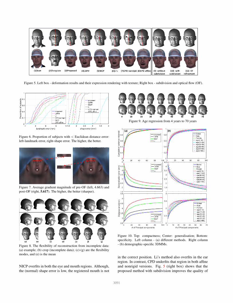
Figure 5. Left box - deformation results and their expression rendering with texture; Right box - subdivision and optical flow (OF).
Figure 6. Proportion of subjects with < Euclidean distance error:
left-landmark error, right-shape error. The higher, the better.
Figure 7. Average gradient magnitude of pre-OF (left, 4.663) and
post-OF (right, 5.617). The higher, the better (sharper).
Figure 8. The flexibility of reconstruction from incomplete data:
(a) example; (b) crop (incomplete data); (c)-(g) are the flexibility
modes, and (e) is the mean
NICP overfits in both the eye and mouth regions. Although,
the (normal) shape error is low, the registered mouth is not
Figure 9. Age regression from 4 years to 70 years
Figure 10. Top: compactness; Center: generalisation; Bottom:
specificity. Left column - (a) different methods. Right column
- (b) demographic-specific 3DMMs.
in the correct position. Li’s method also overfits in the ear
region. In contrast, CPD underfits that region in both affine
and nonrigid versions. Fig. 5 (right box) shows that the
proposed method with subdivision improves the quality of
3091
texture and captures more shape detail. But it also causes
over-fitting in the eye region. The texture map with optical
flow improves that by tuning the correspondence thus mak-
ing the texture sharper, as exemplified by the edge of the
cap. It also keeps more shape detail (see Fig. 5 (11)).
Quantitative evaluation: We use 14 manual facial land-
marks over 100 subjects to measure landmark error of each
template deformation method. As shown in Fig. 6-left, 80%
of landmark errors are less than 6 mm for our method. Fig.
6-right shows that 60% of shape errors from our method are
under 1.7 mm. The shape error is computed by measuring
the nearest point distance from deformed template to raw
scan. Overall, the proposed method outperforms all others.
8.2. Optical flow refinement
We warp all texture maps to the average using optical
flow (OF). As shown in Fig. 7, the optical flow corrects
small misalignments of features such as the eyebrows, chin
and forehead. We computed image sharpness using aver-
age gradient magnitude averaged over 72 pre-OF and post-
OF images. The 1st row of Fig. 5 (10) (11) demonstrates
the outcome of the proposed correspondence refinement.
The optical flow refinement clearly improves the correspon-
dence in the eye regions, yet retains the shape-texture detail.
8.3. Reconstruction and age regression
The task of reconstruction of an unseen example with
missing parts can validate the correspondence quality,
model fitting and generalisation ability. In the first row of
Fig. 8, we fix the shape of the cranium and reconstruct the
full head from that shape, while permitting the shape of the
face to vary. Here we found that most variation occurs over
the chin region. The second row of Fig. 8 is the recon-
struction from the face only, and we note that the princi-
pal variation in reconstructed cranium is from high/short to
low/long. This offers a way to augment existing face models
with a cranium. Reconstruction from one side of the sagit-
tal symmetry plane demonstrates asymmetrical variation of
the head. This application can aid shape-from-shading us-
ing 2D profile images to predict the 3D shape of the self-
occluded half of the face.
Model regression can validate the model’s generalisation
ability on some property (eg. age, gender). Fig. 9 demon-
strates a sequence of 3D images generated from age regres-
sion of the proposed model, ranging from 4 to 70 years.
Note that the cranium develops before the face in children,
and the shape of the cranium is not changing in adults.
8.4. Model evaluation
For quantitative model evaluation, Styner et al [31] give
detailed descriptions of three metrics: compactness, gener-
alisation and specificity. The compactness of the model de-
scribes the number of parameters required to express some
fraction of the variance in the training set, fewer is better.
We use the same subjects as in Sec.8.1 to build 3DMMs.
As can be from Fig.10 (a), the proposed method has bet-
ter compactness than other methods. The proposed method
has the lowest generalisation error, which implies that pro-
posed method has the best performance in describing un-
seen examples. LSFM [10] is comparable with the proposed
method in generalisation ability. Specificity measures how
well a model is able to generate instances that are similar
to real data. The proposed method has the lowest distance
error, which implies that the proposed method is best at gen-
erating instances close to real data.
In Fig.10 (b), LYHM-global is built using 1212 sub-
jects along with several demographic-specific 3DMMs. The
LYHM-(age 0-16) is the most compact 3DMM. When up
to 30 principle components are used, this also has the best
generalisation ability. When more than 30 principle com-
ponents are used, LYHM-global, LYHM-male and LYHM-
female are superior to others in generalisation. The LYHM-
male is best in specificity when up to 30 PCs are used.
9. Conclusion
We proposed a fully-automatic 3DMM training pipeline
and used it to build the first shape-texture 3DMM of the full
head. The correspondence framework avoids over-fitting
and under-fitting in template morphing, and captures high
quality texture in a refinement stage. The proposed 3DMMs
have a powerful ability in reconstruction of incomplete data
and model regression to observe the influence of age on
craniofacial growth. The flexibility of reconstruction from
incomplete craniofacial data helps in many computer vision
applications.
Acknowledgements
We thank Google Faculty Awards, the Royal Academy of
Engineering and the Leverhulme Trust for their support.
Headspace data collection was supported by QIDIS from
the National Commissioning Group. We also thank Rachel
Armstrong, Headspace project coordinator.
References
[1] Alder hey headspace project. http://www.alderhey.
nhs.uk/departments/craniofacial/
headspace-project/. 1, 2
[2] T. Albrecht, R. Knothe, and T. Vetter. Modeling the re-
maining flexibility of partially fixed statistical shape models.
In 2nd MICCAI Workshop on Mathematical Foundations of
Computational Anatomy, pages 160–169, 2008. 6
[3] B. Amberg, S. Romdhani, and T. Vetter. Optimal step non-
rigid icp algorithms for surface registration. In Proceedings
of CVPR., pages 1–8, 2007. 2, 6
3092
[4] P. Anandan. A computational framework and an algorithm
for the measurement of visual motion. International Journal
of Computer Vision, 2(3):283–310, 1989. 2
[5] S. Baker, D. Scharstein, J. Lewis, S. Roth, M. J. Black, and
R. Szeliski. A database and evaluation methodology for opti-
cal flow. International Journal of Computer Vision, 92(1):1–
31, 2011. 2, 5
[6] R. Ball. Sizechina: A 3d anthropometric survey of the chi-
nese head. 2011. 3
[7] V. Blanz and T. Vetter. A morphable model for the synthe-
sis of 3d faces. In Proceedings of Computer graphics and
interactive techniques, pages 187–194, 1999. 1, 2
[8] V. Blanz and T. Vetter. Face recognition based on fitting a 3d
morphable model. IEEE Transactions on pattern analysis
and machine intelligence, 25(9):1063–1074, 2003. 1
[9] F. Bogo, J. Romero, M. Loper, and M. J. Black. Faust:
Dataset and evaluation for 3d mesh registration. In Proceed-
ings of CVPR, pages 3794–3801, 2014. 2
[10] J. Booth, A. Roussos, S. Zafeiriou, A. Ponniah, and D. Dun-
away. A 3d morphable model learnt from 10,000 faces. In
Proceedings of CVPR, pages 5543–5552, 2016. 2, 3, 6, 8
[11] A. Bruhn and J. Weickert. Towards ultimate motion esti-
mation: Combining highest accuracy with real-time perfor-
mance. In Proceedings of ICCV, volume 1, pages 749–755,
2005. 2
[12] T. F. Cootes, G. J. Edwards, and C. J. Taylor. Active appear-
ance models. IEEE Transactions on pattern analysis and
machine intelligence, 23(6):681–685, 2001. 2
[13] D. Cosker, E. Krumhuber, and A. Hilton. A facs valid 3d dy-
namic action unit database with applications to 3d dynamic
morphable facial modeling. In Proceedings of ICCV, pages
2296–2303. IEEE, 2011. 2
[14] C. Creusot, N. E. Pears, and J. Austin. A machine-
learning approach to keypoint detection and landmarking on
3d meshes. Int. Journ. Computer Vision, (1):146–179, 2013.
3
[15] M. De Smet and L. Van Gool. Optimal regions for linear
model-based 3d face reconstruction. In Proceedings of Asian
Conference on Computer Vision, pages 276–289, 2010. 2
[16] C. Duncan, H. Dai, N. Pears, and W. Smith. A novel shape
based outcomes analysis tool for craniofacial surgeons. In
17th Biennial Congress of the International Society of Cran-
iofacial Surgery (ISCFS), 2017. 1, 2
[17] D. Haase, E. Rodner, and J. Denzler. Instance-weighted
transfer learning of active appearance models. In Proceed-
ings of CVPR, pages 1426–1433, 2014. 2
[18] M. Hinze and S. Volkwein. Proper orthogonal decomposition
surrogate models for nonlinear dynamical systems: Error es-
timates and suboptimal control. In Dimension reduction of
large-scale systems, pages 261–306. 2005. 6
[19] B. K. Horn and B. G. Schunck. Determining optical flow.
Artificial intelligence, 17(1-3):185–203, 1981. 2
[20] V. Lempitsky, S. Roth, and C. Rother. Fusionflow: Discrete-
continuous optimization for optical flow estimation. In Pro-
ceedings of CVPR, pages 1–8, 2008. 2
[21] S. Liang, L. G. Shapiro, and I. Kemelmacher-Shlizerman.
Head reconstruction from internet photos. In Proceedings of
ECCV, pages 360–374, 2016. 1
[22] Li.H, W. Sumner, and M. Pauly. Global correspondence op-
timization for non-rigid registration of depth scans. In Com-
puter graphics forum, volume 27, pages 1421–1430, 2008.
2, 6
[23] A. Myronenko and X. Song. Point set registration: Coher-
ent point drift. IEEE transactions on pattern analysis and
machine intelligence, 32(12):2262–2275, 2010. 2, 4, 6
[24] A. Patel and W. A. Smith. 3d morphable face models re-
visited. In Proceedings of CVPR 2009., pages 1327–1334,
2009. 2
[25] P. Paysan, R. Knothe, B. Amberg, S. Romdhani, and T. Vet-
ter. A 3d face model for pose and illumination invariant face
recognition. In Proceedings of Advanced video and signal
based surveillance., pages 296–301, 2009. 2
[26] P. J. Phillips, P. J. Flynn, T. Scruggs, K. W. Bowyer, J. Chang,
K. Hoffman, J. Marques, J. Min, and W. Worek. Overview
of the face recognition grand challenge. In Proceedings of
CVPR., volume 1, pages 947–954, 2005. 3
[27] J. Roth, Y. Tong, and X. Liu. Adaptive 3d face reconstruc-
tion from unconstrained photo collections. In Proceedings of
CVPR, pages 4197–4206. 2
[28] A. Salazar, S. Wuhrer, C. Shu, and F. Prieto. Fully automatic
expression-invariant face correspondence. Machine Vision
and Applications, 25(4):859–879, 2014. 2
[29] M. Sharif, K. Ayub, D. Sattar, M. Raza, and S. Mohsin. En-
hanced and fast face recognition by hashing algorithm. Ap-
plied research and technology, 10(4):607–617, 2012. 3
[30] B. M. Smith and L. Zhang. Joint face alignment with non-
parametric shape models. In Proceedings of ECCV, pages
43–56, 2012. 2
[31] M. A. Styner, K. T. Rajamani, L.-P. Nolte, G. Zsemlye,
G. Szekely, C. J. Taylor, and R. H. Davies. Evaluation of
3d correspondence methods for model building. In Biennial
International Conference on Information Processing in Med-
ical Imaging, pages 63–75, 2003. 8
[32] P. A. Tresadern, P. Sauer, and T. F. Cootes. Additive update
predictors in active appearance models. In Proceedings of
BMVC, volume 2, page 4, 2010. 2
[33] M. Wardetzky, M. Bergou, D. Harmon, D. Zorin, and
E. Grinspun. Discrete quadratic curvature energies. Com-
puter Aided Geometric Design, 24(8-9):499–518, 2007. 6
[34] A. Wedel, T. Pock, C. Zach, H. Bischof, and D. Cremers.
An improved algorithm for tv-l1 optical flow, statistical and
geometrical approaches to visual motion analysis, 2009. 2
[35] L. Wiskott, N. Kruger, N. Kuiger, and C. Von Der Malsburg.
Face recognition by elastic bunch graph matching. IEEE
Transactions on pattern analysis and machine intelligence,
19(7):775–779, 1997. 2
[36] F. Zhou, J. Brandt, and Z. Lin. Exemplar-based graph match-
ing for robust facial landmark localization. In Proceedings
of ICCV, pages 1025–1032, 2013. 2
[37] X. Zhu and D. Ramanan. Face detection, pose estimation,
and landmark localization in the wild. In Proceedings of
CVPR, pages 2879–2886, 2012. 2, 3
3093