Embed Size (px)
Citation preview

Paper # 07F57 Topic: Modeling
1
2007 Fall Meeting of the Western States Section of the Combustion Institute
Sandia National Laboratories, Livermore, CA
October 16 & 17, 2007.
A 3D DNS study of the stabilization of a turbulent lifted
hydrogen/air jet flame in an autoignitive heated coflow
Chun Sang Yoo1,∗ Jacqueline H. Chen
1, and Ramanan Sankaran
2
1Combustion Research Facility, Sandia National Laboratories,
7011 East Ave., Livermore, California 94551-0696, USA
2National Center for Computational Sciences,
Oak Ridge National Laboratories, Oak Ridge, TN37831-6008, USA
Direct numerical simulation (DNS) of the near field of a three-dimensional spatially developing
turbulent slot-burner lifted jet flame in heated coflow is performed with a detailed hydrogen-air
mechanism and mixture averaged transport properties at a jet Reynolds number of 11,000 with
over 900 million grid points. The results show that auto-ignition in a fuel-lean mixture
immediately upstream of the flame base is the main source of stabilization of the lifted jet flame.
Radical chain propagation through H + O2 + M → HO2 + M and HO2 + H → OH + OH is found to
facilitate auto-ignition in both fuel-rich and fuel-lean mixtures. Independent of the chemical
signature of autoignition, examination of the Damköhler number and key intermediate species
behavior near the leading edge of the lifted flame also verify that auto-ignition occurs at the flame
base. The flame index shows that both lean premixed and nonpremixed flame modes exist at the
flame base but most heat is released from the nonpremixed flame mode. Further downstream,
bimodal combustion in the form of rich premixed and nonpremixed flame modes emerges in the
flame index space. The DNS of the near field precludes the transition to a fully nonpremixed
flame anticipated in the far-field of the jet. Lagrangian tracking of the flame base reveals the
passage of coherent jet structures and their correlation with the location of the flame base. In
particular, the relative position of the flame base and the coherent jet structure induces a cyclic
movement of the flame base both in the transverse and axial directions about a mean stabilization
height consistent with Su et al. hypothesis [L.K. Su, O.S. Sun, M.G. Mungal, Combust. Flame 144
(2006) 494−512]. This is determined by Lagrangian tracking of key scalars, heat release rate, and
velocity fields at the stabilization point.
1. Introduction
Turbulent lifted flames have been widely investigated due to their important role both in
practical applications such as direct injection stratified spark ignition engines, diesel engines and
commercial boilers, and in understanding fundamental combustion phenomena as a building-
block flame. In particular, the stabilization mechanism of a lifted flame base has drawn great
attention because the lifted flame base determines the overall flame stability and the
characteristics of combustion systems [1−3]. Despite the importance of flame base stabilization,
however, there has thus far been little consensus among researchers regarding the dominant
mechanism which stabilizes the lifted flame base, not only because of the complex structure and
propagation characteristics of turbulent lifted flames, but also because of of the difficulty in
∗ Corresponding author: [email protected]

2007 Fall Meeting of WSS/CI – Paper # 07F-57 Topic: Modeling
2
obtaining three-dimensional measurements of key scalars in concert with the velocity field.
Several theories have been proposed to explain the stabilization mechanism of turbulent lifted
jet flames, which can broadly be categorized into two or three categories based on the
premixedness of the mixture upstream of the flame base, or on the effect of local turbulence
structure [1−3]. Depending upon the degree of fuel-air premixing upstream of the flame base,
theories can be classified as: premixed flame theory, nonpremixed flamelet theory, and edge
flame theory. In early experimental studies [4, 5], the mixture upstream of the lifted flame base
is postulated to be premixed, and thus, the lifted flame is thought to stabilize where the relevant
turbulent flame speed balances the local flow velocity. In the nonpremixed flamelet theory, it is
proposed that combustion at the lifted flame base resembles an ensemble of laminar flamelets
such that the flame stabilizes where the local scalar dissipation rate is below a critical value [6].
For that reason, the nonpremixed flamelet theory is often called the critical scalar dissipation
concept [1]. The edge flame theory, which combines elements of both premixed and
nonpremixed flames, has been proposed [7−9] since partially-premixed flames were
experimentally reported and found to play a critical role in stabilizing laminar nonpremixed jet
flames [9−11]. According to the edge flame theory, the lifted flame base stabilizes where the
edge flame propagation speed, which is two to three times larger than the laminar flame speed,
matches the local flow velocity.
Second, stabilization theories can be categorized based on the turbulence structure – i.e.
turbulence intensity theory and large-eddy theory. According to the turbulence intensity theory
which is directly related to the premixed flame theory as well as the edge flame theory, the
turbulence intensity at the flame base controls the propagation speed of the base by enhancing
turbulent burning rates through flame area generation and flame propagation speed [5, 8] and
thus, a lifted flame can stabilize even at a position where the local flow velocity is considerably
larger than the laminar flame speed. On the contrary, the large-eddy theory assumes that a flame
edge is able to propagate from one large eddy to another by moving along the flammable
mixture, and thus, the flame edge stabilizes by oscillating with the passage of large eddy
structures [12, 13].
The above theories are sometimes contradictory to one another, but sometimes
complementary, depending upon the particular flames investigated. As an alternative to the
proposed theories, there have been attempts to explain the stabilization mechanism by combining
several key elements from the theories [8, 13, 14]. However, definitive evidence substantiating
the postulated mixed stabilization mechanisms is still unattainable due to inherent limitations in
measurements.
Recently, auto-ignition was proposed as another important stabilization mechanism of lifted
flames in a heated coflow [15, 16]. Since auto-ignition can assist in stabilizing a turbulent flame
base, recirculating hot combustion products has been adopted in bluff-body or swirl-stabilized
burners. For example, in diesel engines, fuel is injected and mixed with a heated oxidizer coflow
in the chamber at temperatures above the ignition limit, such that the stability and overall
characteristics of the lifted flame and soot processes are highly affected by the heated oxidizer
stream [17].
In addition to the numerous experimental studies on flame stabilization, recently a few direct
numerical simulations (DNS) of turbulent lifted jet flames have been performed [18−21]. In contrast to experiments in which only a few flame markers and the velocity field can be
measured in two dimensions, DNS can provide full characterization of the flame structure and
flow field near the flame base. Takeno and his coworkers introduced the concept of a flame

2007 Fall Meeting of WSS/CI – Paper # 07F-57 Topic: Modeling
3
index, the inner product of fuel and oxidizer gradients, to distinguish premixed flame zones from
the prevailing nonpremixed flame in two-dimensional turbulent lifted jet flames [18]. Recently,
stabilization characteristics of a lifted jet flame in a heated shear layer were investigated using a
two-dimensional DNS with single-step global chemistry by Jiménez and Cuenot [19], in which
re-ignition triggered by recirculated hot gas was found to be the key mechanism to stabilize the
lifted triple flame along with the passage of large scale flow structures. While providing
qualitative insights regarding the roles of auto-ignition and edge propagation, this study did not
include realistic timescales associated with ignition kinetics relative to mixing time scales in a
turbulent shear flow owing to the two-dimensional configuration and the simple chemistry.
Mizobuchi et al. [20, 21] performed a three-dimensional DNS of a turbulent lifted hydrogen jet
flame in an ambient coflow of oxidizer with detailed chemistry and identified the existence of
nonpremixed flame islands. Their results support the premixed flame theory, primarily because
the lift-off height is well correlated with the empirical equation proposed by Kalghatgi [5].
In the present study, the stabilization mechanism of a turbulent lifted hydrogen jet flame in a
heated coflow is investigated by performing three-dimensional DNS with detailed hydrogen/air
chemistry. While this is the first three-dimensional DNS with detailed chemistry performed of
this configuration, there have been transported probability density function (pdf) methods
applied to the experimental Cabra burner [15, 22−26], in which the lift-off height is predicted with reasonable accuracy. These models also show that the lift-off height is sensitive to the
recombination reaction, H + O2 + M → HO2 + M and that HO2 exists upstream of other
intermediate species. It is also found that the lift-off height is highly sensitive to a certain range
of coflow temperature [23]. This result implies that the ignition delay, which has its minimum in
a fuel-lean mixture rather than at the stoichiometric mixture, can significantly affect the
stabilization of a lifted flame in the Cabra burner configuration [27]. These flame characteristics
from the studies with the pdf method suggest that auto-ignition occurs at the flame base. Like
the pdf methods, the conditional moment closure (CMC) approach for the Cabra flame also
shows similar flame characteristics [28]. Thus, in the present DNS study the role of auto-
ignition resulting from the heated coflow is examined in detail to determine the stabilization
mechanism of the flame. In addition, the instantaneous and time-averaged flow field in the
vicinity of the flame base is characterized and its role in stabilization elucidated. Finally, the
flame structure is characterized at different axial locations along with the conditional flame
statistics.
2. Problem configuration
The simulation was performed in a three-dimensional slot-burner configuration. Fuel issues from
a central jet, which consists of 65% hydrogen and 35% nitrogen by volume with an inlet
temperature of 400K. The central jet is surrounded on either side by co-flowing heated air at
1,100K. This temperature is greater than the crossover temperature of hydrogen-air chemistry
[29], such that the mixture upstream of the flame base is auto-ignitable.
The simulation parameters are given in Table 1. A uniform grid spacing of 15µm was used in
the streamwise direction, x, and spanwise direction, z, while an algebraically stretched mesh was
used in the transverse direction, y, obtained from y(s) = f(s) × s, where s is the equi-spaced
computational grid and 0 ≤ s ≤ 1. The stretching function is given by,
2007 Fall Meeting of WSS/CI – Paper # 07F-57 Topic: Modeling
4
Table 1 : Numerical and physical parameters of the DNS
Parameter
Slot width (h) 1.92mm
Domain size in the streamwise, transverse and spanwise
directions (Lx × Ly × Lz) 12.5h × 16.7h × 3.3h
Number of grid points 1600 × 1372 × 430 ≈ 944 M
Turbulent jet velocity (U) 347.0m/s
Laminar coflow velocity 4.0m/s
Jet Reynolds number (Rejet = Uh/ν) 11200
Turbulent intensity1 (u′/U) 0.087
Turbulent length scale1, 2 (lt/h) 0.78
Turbulent Reynolds number1, 2 (Ret = u′lt/ν) 360
( )sess
ssf ks βσ
β −
−++=
*
tanh12
1)( (1)
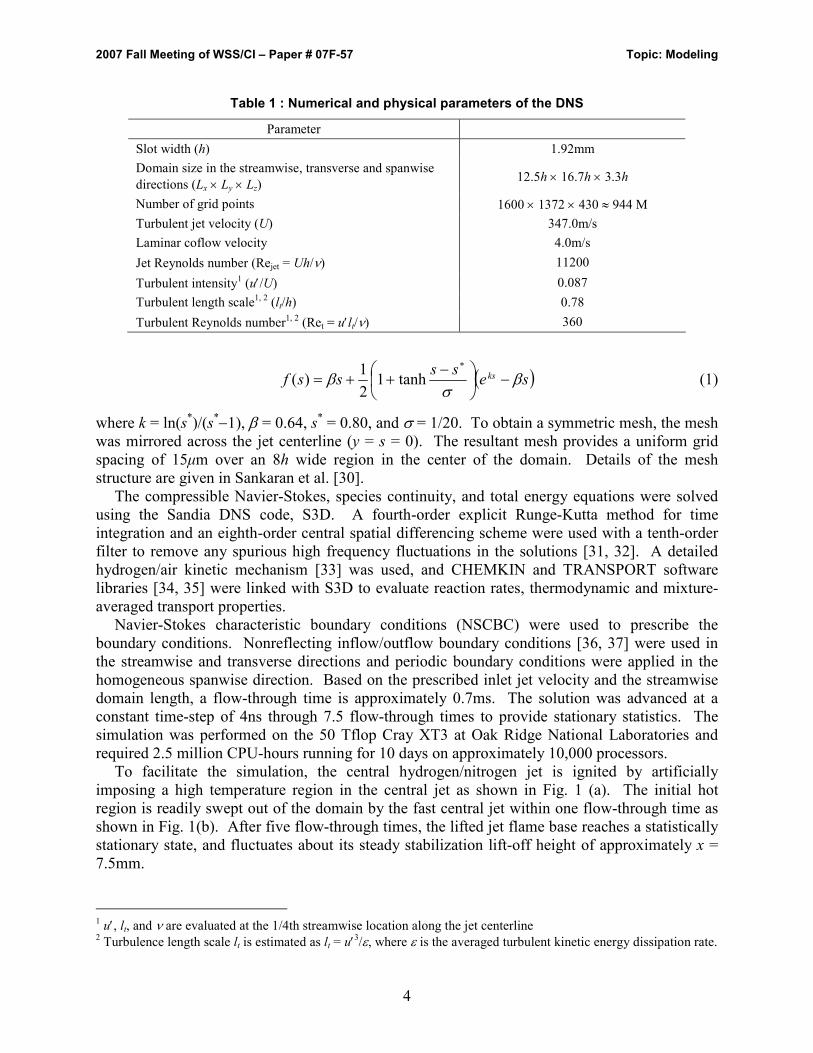
where k = ln(s*)/(s
*−1), β = 0.64, s* = 0.80, and σ = 1/20. To obtain a symmetric mesh, the mesh
was mirrored across the jet centerline (y = s = 0). The resultant mesh provides a uniform grid
spacing of 15µm over an 8h wide region in the center of the domain. Details of the mesh
structure are given in Sankaran et al. [30].
The compressible Navier-Stokes, species continuity, and total energy equations were solved
using the Sandia DNS code, S3D. A fourth-order explicit Runge-Kutta method for time
integration and an eighth-order central spatial differencing scheme were used with a tenth-order
filter to remove any spurious high frequency fluctuations in the solutions [31, 32]. A detailed
hydrogen/air kinetic mechanism [33] was used, and CHEMKIN and TRANSPORT software
libraries [34, 35] were linked with S3D to evaluate reaction rates, thermodynamic and mixture-
averaged transport properties.
Navier-Stokes characteristic boundary conditions (NSCBC) were used to prescribe the
boundary conditions. Nonreflecting inflow/outflow boundary conditions [36, 37] were used in
the streamwise and transverse directions and periodic boundary conditions were applied in the
homogeneous spanwise direction. Based on the prescribed inlet jet velocity and the streamwise
domain length, a flow-through time is approximately 0.7ms. The solution was advanced at a
constant time-step of 4ns through 7.5 flow-through times to provide stationary statistics. The
simulation was performed on the 50 Tflop Cray XT3 at Oak Ridge National Laboratories and
required 2.5 million CPU-hours running for 10 days on approximately 10,000 processors.
To facilitate the simulation, the central hydrogen/nitrogen jet is ignited by artificially
imposing a high temperature region in the central jet as shown in Fig. 1 (a). The initial hot
region is readily swept out of the domain by the fast central jet within one flow-through time as
shown in Fig. 1(b). After five flow-through times, the lifted jet flame base reaches a statistically
stationary state, and fluctuates about its steady stabilization lift-off height of approximately x =
7.5mm.
1 u′, lt, and ν are evaluated at the 1/4th streamwise location along the jet centerline
2 Turbulence length scale lt is estimated as lt = u′
3/ε, where ε is the averaged turbulent kinetic energy dissipation rate.

2007 Fall Meeting of WSS/CI – Paper # 07F-57 Topic: Modeling
5
Figure 1. Temperature isocontours in the plane, z = 0, at (a) t = 0.0 and (b) 0.03 ms.
3. Results and discussion
The global structure of the flame stabilization base is revealed from instantaneous images of the
flame structure at different times. Figure 2 shows the instantaneous isocontours of the mass
fraction of hydroxyl (YOH), which is often used as an experimental marker of the lifted flame
base [12, 38], superimposed on the iso-surface of stoichiometric mixture fraction, (ξst = 0.1990) at t = 0.42ms (approximately six flow-through times). The mixture fraction is computed using
Bilger’s formula [39] based on the elemental mass fractions of the fuel and oxidizer. At first
glance, one can see that fine flow structures upstream of the flame base are readily dissipated as
the flow traverses downstream, primarily due to the effect of heat release by the flame [40]. In
addition, the flame base is highly irregular and strongly affected by the instantaneous local flow
and mixture conditions such that the stabilization of the lifted jet flame is not a global
phenomenon, but rather, a highly localized phenomenon.
Although three-dimensional volume rendering provides a description of global features
pertaining to the flame structure, they are too complex to extract details regarding the lifted
flame. Instead, instantaneous snapshots of a two-dimensional x-y plane are extracted from the
Figure 2. Isocontours of the mass fraction of hydroxyl radical (OH) superimposed on the iso-
surface of stoichiometric mixture fraction (ξξξξst = 0.199) at 0.42ms; (b) is another image of (a) viewed from the spanwise direction, z.

2007 Fall Meeting of WSS/CI – Paper # 07F-57 Topic: Modeling
6
Figure 3. From left to right, isocontours of temperature, heat release rate, YOH and YHO2 in the plane z = 0 at t = 0.42ms. The solid red line denotes the stoichiometric mixture fraction.
three-dimensional data. Figure 3 shows the isocontours of temperature, heat release rate, OH
and HO2 mass fractions on the z = 0 plane at t = 0.42ms. One can readily observe that the flame
base stabilizes in a fuel-lean mixture rather than at the stoichiometric mixture, which is
insensitive to the definition of the flame base. Moreover, it is clear that HO2 radical accumulates
upstream of OH and other high-temperature radicals such as H and O which are not shown here.
HO2 radical is a precursor of auto-ignition in hydrogen-air chemistry [24, 29, 41] so that the
existence of HO2 radical upstream of other intermediate radicals indicates that the stabilization
mechanism of the lifted flame base is due to auto-ignition by heated coflow rather than normal
flame propagation [24].
In the following sections, details of the lifted flame stabilization mechanism will be presented
in terms of the instantaneous flame and flow structures at different axial and spanwise locations
in the jet, along with averaged and conditional mean flame statistics..
3.1. Ignition/extinction processes at the flame base
To understand in detail what happens near the flame base, we investigate the temporal evolution
of the flame and flow characteristics. Figure 4 shows a typical sequence of images of YOH, YHO2,
temperature, and scalar dissipation rate, χ isocontours at the leading edge of the lifted jet flame
between t = 0.37 and 0.44ms. The scalar dissipation rate is defined by [3, 41]:
2
2 ξαχ ∇= , (2)
where α is the thermal diffusivity. As mentioned before, OH is a good marker of the high-
temperature flame zone, whereas HO2 is a good marker of a precursor of auto-ignition upstream
of the flame base. Also shown in the figure are the stoichiometric mixture fraction isoline and
the instantaneous velocity vectors. Note that the leading edge shown here corresponds to the left
branch of the lifted flame, and hence, the centerline of the fuel jet lies to the right side of each
figure (not shown in the figures). Several important characteristics of the lifted flame are
deduced from this and many other similar image sequences. First, the flame base moves
upstream following a fuel-lean mixture, and not the stoichiometric mixture fraction as previously
mentioned. Second, it is readily observed that a pool of HO2 exists ahead of the OH radical that

2007 Fall Meeting of WSS/CI – Paper # 07F-57 Topic: Modeling
7

2007 Fall Meeting of WSS/CI – Paper # 07F-57 Topic: Modeling
8
Figure 4. Sequential images of (a) YOH, (b) YHO2, (c) temperature, and (d) scalar dissipation rate isocontours (color flood) at the leading edge on the left branch of the lifted flame with velocity
field (white arrowed line) and stoichiometric mixture fraction isoline (solid red line) from t = 0.37 to
0.44ms in 0.01ms increments.

2007 Fall Meeting of WSS/CI – Paper # 07F-57 Topic: Modeling
9
enhances the movement of the ignition front upstream. Third, while moving upstream (e.g.
between t = 0.37 and 0.40ms), the flame base is convected by a positive spanwise vortex (ωz > 0)
which helps to stabilize the base and/or assist in its propagation.
In fuel-lean mixtures, we identify several local maxima of YOH and temperature, which
indicate auto-ignition occurring at the locations. In general, propagating flames such as edge
flames and premixed flames exhibit temperature or species profiles which change monotonically
from unburned mixture temperature to burned gas temperature or from reactants to products.
Therefore, the presence of several local maxima of temperature or species mass fraction across
or along a flames is unlikely, unless local extinction occurs. In the present case, however, the
scalar dissipation rates in the fuel-lean mixtures are considerably less than the extinction scalar
dissipation rate, χq of the corresponding strained laminar nonpremixed flames (note that χq ≈ 10,400s
-1 at ξst for this particular flame, which is evaluated using OPPDIF code [42] at the
extinction point). Therefore, it can be hypothesized that at the flame base, auto-ignition occurs
in the fuel-lean mixtures such that the flame base is a spontaneous ignition front even though it
resembles an edge flame.
In addition to the topology of the temperature and species fields, it is of interest to note the
characteristics of the elementary reaction rates related to HO2 production at different axial
positions to identify the chemical signature of the ignition process. The importance of HO2
radical to the chemical runaway was already investigated by several previous studies in both one-
dimensional laminar counterflow and two-dimensional turbulent mixing layer configurations
[43−45]. In the studies, it was found that during the early stages of radical ignition, HO2 is
mainly produced by the recombination reaction, H + O2 + M → HO2 + M (R9), while the
consumption of HO2 radical by the chain-branching reaction, HO2 + H → OH + OH (R11), is
negligible such that the net production of HO2 is primarily dominated by R9. For selected
elementary reactions involved in the H2/air chemistry, readers are referred to Table 2. However,
at a later time near the ignition point, the consumption of HO2 by R11 offsets the production by
R9 such that the net production of HO2 becomes negligible [45].
Similar to the previous studies, we identify characteristics of the radical ignition process
occurring at different downstream axial locations. Figure 5 presents the profiles of the
elementary reaction rates of HO2 and temperature at several axial locations. Upstream of the
flame base as shown in Figs. 5(a) and (b), one can identify the dominant production of HO2 by
R9 and negligible HO2 consumption by R10 ~ R12. Near the flame base as shown in Fig. 5(c),
however, it can be identified that R11 balances R9 along with R10 and R12, and thus, one can
deduce that ignition occurs near the flame base. Further downstream (Fig. 5(d)), we still notice
that R11 balances R9 with two different peaks in the reaction rates. The first peak at x =
Table 2: Selected elementary H2/O2/N2 reactions (Units are cm
3-mol-s-kcal-K,
and k = ATn exp(−E/RT) from Ref [33])
A N E
R1 : H + O2 ↔ O + OH 3.547E+15 -0.406 1.6599E+04
R2 : H2 + O ↔ OH + H 0.508E+05 2.670 0.6290E+04
R3 : OH + H2 ↔ H + H2O 0.216E+09 1.510 0.3430E+04
R9 : O2 + H + M ↔ HO2 + M 1.475E+12 0.600 0.0000E+00
R10: H + HO2 ↔ H2 + O2 1.660E+13 0.000 8.2300E+02
R11: H + HO2 ↔ OH + OH 7.079E+13 0.000 2.9500E+02
R12: O + HO2 ↔ OH + O2 3.250E+13 0.000 0.0000E+00

2007 Fall Meeting of WSS/CI – Paper # 07F-57 Topic: Modeling
10
Figure 5. The profiles of the elementary reaction rates of HO2 and temperature at different axial locations: x = 4, 6, 7.5, and 9mm from (a) to (d).
−2.4mm shows the production and consumption of HO2 in a flame and the second peak at x =
−1.8mm indicates ignition under fuel-rich conditions. The distinction between the ignition and
the flame can be clearly observed in the elementary reactions of OH, which are shown in Fig. 6.
Figure 6. The profiles of the elementary reaction rates of OH and temperature at different axial locations: x = 4, 6, 7.5, and 9mm from (a) to (d).

2007 Fall Meeting of WSS/CI – Paper # 07F-57 Topic: Modeling
11
In Figs. 6 (c) and (d), note that at the ignition spots, R11 becomes quite comparable to or even
larger than R1 and R2 which are the typical chain-branching reactions of the H2−O2 system
under high temperature conditions. However, in the high temperature region the contribution of
R11 to OH production becomes negligible compared to R1 and R2.
It is also of interest to note that re-ignition occurs in fuel-rich mixtures following local flame
extinction. After t = 0.40ms, a region with high scalar dissipation rate, χ (in excess of 10,000s-1) advects toward the flame base and partly extinguishes the flame at t = 0.42ms. However, a high
level of HO2 is convected toward and generated at this region via R9. Subsequently, OH radical
is rapidly generated by the ignition process via R11 along with R1 and R2 as shown in Fig. 6(d).
This result clearly shows that in the present case, R9 and HO2 radical take part in the chain
propagation process, and thus re-ignition occurs immediately following extinction and HO2
generation not only in fuel-lean mixtures but also in fuel-rich mixtures (see figures at t =
0.43ms). Therefore, one can observe that this re-ignition region is demarcated by a depletion in
HO2 and an increase in temperature coincident with an increase in OH by comparing Figs. 4 (a)
~ (c) at t = 0.43ms.
We also identify another interesting ignition process occurring on the right branch of the lifted
flame. Figure 7 shows sequential images of YOH, YHO2, temperature, and χ isocontours at the leading edge on the right branch of the lifted jet flame between t = 0.37 and 0.44ms. In this case,
one can find a negative vortex (ωz < 0) which helps to stabilize the flame base similar to the left
branch of the lifted flame in Fig. 4. Also notable is an ignition process occurring in a fuel-rich
mixture island. At t = 0.37ms, note that there is a rich mixture island in the two-dimensional
plane corresponding to a three-dimensional structure, i.e. a rich mixture arm emanating from the
homogeneous spanwise direction, z. The island contains a high concentration of HO2, and thus
its presence initiates auto-ignition. A few hundredths of a millisecond later, HO2 induces auto-
ignition via R11 which results in the increase of OH and temperature observed in Figs. 7(a) ~ (c).
This result clearly shows that HO2, which is generated in the cold fuel jet and advected to the hot
oxidizer region by local turbulent flow, facilitates ignition in the fuel-lean mixture. Note that
this ignition pattern would not occur in two-dimensional simulations because the rich mixture
island originates from the out-of-plane homogeneous spanwise direction.
To determine whether similar flame characteristics obtained from instantaneous realizations
exist from an averaged point of view, the three-dimensional data is Favre-averaged over time and
the homogeneous direction, z. Figure 8 shows isocontours of averaged temperature, heat release
rate, YOH and YHO2 along with mixture fraction isolines and streamlines. As in the instantaneous
realizations shown above, the average values also show that the flame base lies in a fuel-lean
mixture (i.e. ξ ≈ 0.1) and that HO2 is concentrated upstream of OH. In addition, near the flame
base the streamlines reflect flow redirection which further helps to stabilize the flame base.
From these results, we conclude that auto-ignition in a fuel-lean mixture at the flame base is
the primary method of flame stabilization, and that HO2 radical plays a critical role in initiating
and facilitating the ignition process. Occasionally, auto-ignition in a fuel rich mixture can also
occur near the flame base immediately after flame extinction by high scalar dissipation rate and
in a fuel-rich island issuing from the central core fuel jet, although the probability of occurrence
of ignition in fuel rich mixtures is much lower than in fuel lean mixtures. Finally, spanwise
vortices near the flame base act to reduce the incoming axial core jet velocity, providing
additional shelter for the ignition process.

2007 Fall Meeting of WSS/CI – Paper # 07F-57 Topic: Modeling
12

2007 Fall Meeting of WSS/CI – Paper # 07F-57 Topic: Modeling
13
Figure 7. Sequential images of (a) YOH, (b) YHO2, (c) temperature, and (d) scalar dissipation rate isocontours (color flood) at the leading edge on the right branch of the lifted flame with velocity
field (white arrowed line) and stoichiometric mixture fraction isoline (solid red line) from t = 0.37 to 0.44ms in 0.01ms increments.

2007 Fall Meeting of WSS/CI – Paper # 07F-57 Topic: Modeling
14
Figure 8. Isocontours of Favre averaged temperature, heat release rate, YOH and YHO2 with mixture fraction lines (dashed white line) and streamlines (arrowed black line). All values are averaged
over a time period between 0.35 to 0.51ms and the homogeneous direction, z.
3.2. Flame structure and flame index
To better understand the flame characteristics at different downstream locations, we examine the
flame structure and flame index which is often used to discern premixed flame zones from the
prevailing nonpremixed flame in lifted jet flames [18]. In this study, the normalized flame index
is used, which is defined by:
OF
OF
YY
YYIF
∇⋅∇
∇⋅∇=.. , (3)
where the subscripts F and O represent fuel and oxidizer, respectively.
Figure 9 shows isocontours of heat release rate with the stoichiometric mixture fraction
isoline at several axial locations in the jet flame. The flame index is also superimposed in the
figure to distinguish between premixed and nonpremixed flame modes. Near the flame base (x =
7.5mm), the peak heat release rate occurs in a fuel-lean mixture, but reactants appear to burn in
both premixed and nonpremixed flame modes. At x = 9mm, peak heat release rate occurs near
the stoichiometric mixture and primarily in a premixed flame mode. At x = 12mm, the peak heat
release rate has migrated toward much richer mixtures, and reaction also seems to occur in both
nonpremixed and premixed flame mode. Further downstream (at x = 18 and 21.6mm), heat
release occurs in both fuel-rich and stoichiometric mixtures. In these regions, the premixed
flame mode prevails in fuel-rich mixtures, whereas near stoichiometric conditions, the
nonpremixed flame mode prevails. The correlation between the flame index and heat release
rate will be further elucidated by examining their statistics in the next section.
By examining the flame index, it is readily observed that auto-ignition does not show any bias
towards a particular combustion mode at the leading part of the lifted flame. It is not until
further downstream that the conventional nonpremixed and fuel-rich premixed flames develop
further. Note also that the transition to a fully nonpremixed flame in the absence of a premixed
flame mode is not encountered in the present simulation, where the domain size encompasses
only the near field of the jet. Therefore, at the downstream boundary of the domain the core fuel
jet still exists and thus, fuel-rich premixed flames are also sustained by the core jet.
The detailed flame structure associated with the premixed and nonpremixed flame modes is
obtained by examining several representative cuts from Fig. 9. Figure 10 shows the flame

2007 Fall Meeting of WSS/CI – Paper # 07F-57 Topic: Modeling
15
Figure 9. Isocontours of heat release rate with stoichiometric mixture fraction isoline (solid black line) for different axial, x, locations; 6, 7.5, 9, 12, 18, and 21.6mm. The solid red line and dotted
white line represent the flame index = 0.707 and -0.707 which represent premixed and nonpremixed flame regions, respectively.
Figure 10. Flame structures along the 1D lines in Fig.7; (a) a-a’ at 9mm and (b) b-b’ at 21.6mm.

2007 Fall Meeting of WSS/CI – Paper # 07F-57 Topic: Modeling
16
structures along the cuts (a−a’ at 9mm and b−b’ at 21.6mm) from Fig. 9. Typical premixed and
nonpremixed flame structures are clearly identified in Fig. 10 (a) and (b), respectively. In the
premixed flame, fuel and oxidizer diffuse into the reaction zone from the same direction,
whereas in the nonpremixed flame, they approach the reaction zone from opposite directions.
3.3. Statistics on flame characteristics
In this section, conditional flame statistics are presented to further elucidate the stabilization
mechanism and flame structure, and also to provide useful information for model development
and validation. Figure 11 shows scatter plots of temperature versus mixture fraction at different
axial locations at t = 0.42ms. Open circles and diamonds represent, respectively, the conditional
mean and standard deviation of temperature. The frozen inflow and equilibrium temperature are
also represented by dashed lines. At first glance, one can observe that upstream of the flame
base, the temperature profile deviates from the inflow condition as shown in Figs. 11 (a) and (b).
Due to pressure drop at vortex cores in the mixing layer, mixing of the reactants in the layer
results in a temperature deficit through the entire mixture space relative to the inflow
temperature. In addition to pressure drop effect, the heat capacity of the mixture, cp also depends
on temperature, and thus it may aggravate the temperature deficit in the mixture fraction
coordinate [3]. This temperature drop becomes more significant at downstream axial positions.
Note also that the temperature first increases in a fuel-lean mixture, and subsequently the peak
shifts towards richer mixtures, clearly indicating that ignition occurs first under hot, fuel-lean
conditions where ignition delays are shorter. This has also been demonstrated in previous two-
dimensional DNS of auto-ignition in an inhomogeneous hydrogen/air mixture (see Fig. 9 in Ref.
[41]).
These flame characteristics can also be found in the behavior of the important species mass
fractions and reaction rates. Figures 12 and 13 show the conditional means and standard
deviations of H2, OH, HO2 and H species mass fraction and their reaction rates, respectively.
One can readily observe that the peak reaction rates of each intermediate species spatially
precede the peaks of the corresponding species, and thus, HO2 radical builds up at x = 6mm
Figure 11. Scatter plots of temperature versus mixture fraction for different axial locations; from (a) to (f), x = 2.4, 6, 7.5, 9, 12, and 18 mm. Dashed lines denote inflow and equilibrium
temperatures, and open circles and diamonds denote respectively the conditional mean and standard deviation of temperature.

2007 Fall Meeting of WSS/CI – Paper # 07F-57 Topic: Modeling
17
Figure 12. The conditional means (left) and standard deviations (right) of (a) YH2, (b) YOH, (c) YHO2, and (d) YH for different axial locations at t = 0.42ms.
ahead of OH and H radicals. In the same context, the peaks of HO2 and H radicals move toward
richer mixtures at downstream axial positions because HO2 is produced in a low temperature
region, and H radical is generated under fuel rich conditions in a flame, and thus, the peaks of the
species follow the core jet of cold fuel. However, the peak of OH radical occurs near the
stoichiometric mixture after x = 12mm, which coincides with the peak temperature region. It is
of interest to note that the fuel consumption rate exhibits two peaks at x = 18mm, corresponding
to stoichiometric and rich mixtures, which clearly coincides with the dual existence of
nonpremixed and rich premixed flame modes discussed in section 3.2. Note also that, in general,

2007 Fall Meeting of WSS/CI – Paper # 07F-57 Topic: Modeling
18
Figure 13. The conditional means (left) and standard deviations (right) of the reaction rates of (a)
H2, (b) OH, (c) HO2, and (d) H for different axial locations at t = 0.42ms.
the conditional standard deviations of the mass fractions and reaction rates exhibit their spatial
peaks at x = 9mm, which implies that vigorous reaction and heat release occur at that position,
and hence, generate such large conditional deviations.
The conditional means and standard deviations of heat release rate and flame index are
presented in Fig. 14. The transition of reactions from lean to rich mixtures is also found in the
conditional mean of heat release rate. Finally, twin peaks in the heat release rate form further
downstream of the flame base as observed in the fuel consumption rate. It is also of interest to
note that near the flame base, the conditional mean of the flame index indicates that the
nonpremixed flame mode prevails in a lean mixture where the primary heat release occurs.
However, the existence of both premixed and nonpremixed flame modes in the region is

2007 Fall Meeting of WSS/CI – Paper # 07F-57 Topic: Modeling
19
Figure 14. The conditional means (left) and standard deviations (right) of (a) heat release rate and (b) flame index for different axial locations at t = 0.42ms.
observed as shown in Fig. 9 and thus, the large probability of the nonpremixed flame index
compared to the premixed flame may skew the bias of the conditional mean in lean mixtures.
However, at x = 9 and 12mm, the premixed flame mode prevails in stoichiometric and rich
mixtures with large heat release rate. Further downstream, the nonpremixed flame mode near
stoichiometric mixtures and the premixed flame mode in fuel-rich mixtures prevail, consistent
with the previous discussion.
To further investigate the relation between the flame index and heat release rate, the
conditional mean and fraction of heat release rate at a given flame index are presented in Fig. 15.
The fraction of heat release rate is defined as the product of the conditional mean heat release
rate and the pdf of the flame index, i.e. <Q|F.I.>P(F.I.). Note that the conditional mean of heat
release rate increases nearly linearly with the flame index and exhibits its peak in the premixed
flame mode at all of the axial locations. However, in the fraction of heat release rate, a clear
bimodal combustion behavior is observed except near the flame base (x = 7.5) where heat release
rate is mostly generated in the nonpremixed flame mode due to its high probability in spite of the
small conditional mean of heat release rate.
To determine the relative importance of turbulent mixing with auto-ignition on the
stabilization mechanism, the scalar dissipation rate, χ and the Damköhler number, Da are
investigated to isolate each effect. While the build-up of HO2 upstream of other intermediate
species (H, OH, and O) and the analysis of the elementary reactions in the previous section
provide the evidence of auto-ignition at the flame base [24, 45], Da based on species reaction and
diffusion terms provides quantitative information regarding the progress of ignition. Significant
losses of heat and radicals due to high scalar dissipation rate can impede or cause ignition
progress to slow down or cease [41] as manifested by small values of Da ~ O(<1). In this study,
OH radical is chosen to evaluate Da since its exponential growth through chain branching at the
expense of a near constant dissipative loss, provides independent evidence of ignition. Da is

2007 Fall Meeting of WSS/CI – Paper # 07F-57 Topic: Modeling
20
Figure 15. The conditional mean (a) and fraction (b) of heat release rate at a given flame index with a cutoff value of 0.01 J/mm
3s at t = 0.42ms.
defined as [41]:
)(/ ,kjkj
k
kVYx
Daρ
ω∂∂−
=&
, (4)
where the subscript k denotes the k-th species with a mass fraction, Yk, a diffusive velocity in the
j direction, Vj,k, and a net production rate, kω& .
The conditional means and standard deviations of scalar dissipation rate and Damköhler
number based on OH, DaOH are presented in Fig. 16. It is of interest to note that the conditional
mean of scalar dissipation rate is substantially lower than the extinction scalar dissipation rate, χq (≈ 10,400s-1 at ξst as mentioned in section 3.1) of a strained laminar nonpremixed flame, even
near the fuel jet nozzle, and it becomes an order of magnitude smaller than χq near the flame
base. From this perspective, the nonpremixed flamelet theory which conjectures that a lifted
flame stabilizes where the local scalar dissipation rate decreases below a critical value, or the
extinction scalar dissipation rate, is not the mechanism by which the flame stabilizes. This
problem with the nonpremixed flamelet theory was previously reported [3, 4].
In the present case, however, the ignition scalar dissipation rate, χi should also be considered to evaluate the theory because auto-ignition is a convincing stabilization mechanism. As shown
in Fig. 16(a), one can notice that the conditional mean of χ is much larger than the ignition scalar
dissipation rate, χi (≈ 65s-1 at ξst). However, although the conditional mean of χ is larger than χi, the probability of local χ below χi is substantial because the conditional standard deviation of χ is quite comparable to the conditional mean of χ . Thus, one may imagine that auto-ignition
could happen even upstream of the flame base at mixtures with χ being below χi. This interpretation also implies that the ignition delay time must be taken into account to properly
determine the lift-off height and flame base stabilization. Otherwise, the lift-off height evaluated

2007 Fall Meeting of WSS/CI – Paper # 07F-57 Topic: Modeling
21
Figure 16. The conditional means (left) and standard deviations (right) of (a) scalar dissipation rate and (b) DaOH for different axial locations at t = 0.42ms.
with χi alone would be much smaller than the actual lift-off height. To better understand the
temporal evolution of ignition near the flame base in time, Lagrangian fluid particle and flame
element tracking capabilities [46, 47] are needed and an area of current investigation.
Unlike the characteristics of the scalar dissipation rate, the conditional mean of DaOH in Fig.
16 (b) clearly shows that auto-ignition is the main source of stabilization of the lifted flame,
since DaOH of a lean mixture at the flame base is of order ten, and not unity as it would be in a
flame. Further downstream, DaOH approaches unity throughout the entire mixture, which
indicates a transition from auto-ignition to premixed or nonpremixed flames where reaction
balances diffusion. However, a large standard deviation still exists downstream of the flame
base (x = 12mm), suggesting that there still exists local auto-ignition in fuel-rich mixtures with
large Damköhler number even if its probability is lower than that of conventional flames.
In addition to the Damköhler number analysis, the speed of the flame base also indicates auto-
ignition. Note that before the flame base attains a steady-state, it propagates upstream at
approximately 60m/s in the laboratory reference frame. Even without considering the oncoming
high axial velocity, this flame speed is much larger than the laminar flame speed corresponding
to the stoichiometric mixture in the present study at high temperature (e.g. sL ~ 11.6m/s at 800K)
[48], which confirms that the flame base is not a deflagration wave but a spontaneous subsonic
ignition front [49].
3.4. A stabilization mechanism
From the previous sections, it is now apparent that the main stabilization mechanism of the
present lifted jet flame is the auto-ignition of the fuel-lean mixtures by the hot coflow. However,
the stabilization point is also found to fluctuate in time and space, and cannot be determined as a
single value. Thus, in this section, another stabilization mechanism which may compete with
auto-ignition will be sought to identify the fluctuations.

2007 Fall Meeting of WSS/CI – Paper # 07F-57 Topic: Modeling
22
Figure 17. Scatter plot of the stabilization locations at both left and right braches with two definitions of the flame base at z = 0 plane from t = 0.35 ~ 0.51ms
To understand the fluctuations of the stabilization point, we first examined the locus of a
stabilization point which is defined as the most upstream value of YOH = 0.001 and YOH = 0.005
isolines at z = 0 plane as shown in Fig. 17. The most upstream point of YOH = 0.001 and YOH =
0.005 isolines represent the inception points of ignition and high temperature region respectively.
Note that in both branches the stabilization points form a cycle and the periods of the cycles vary
from 0.1 to 0.15ms. However, it can also be observed that besides the long cyclic movement of
the points, there are other oscillations with high frequency.
From the results and based on the proposed stabilization theories, it can be postulated that a
flame base fluctuates with a series of small vortices passing (small scale turbulence) [4, 5] and/or
with large scale eddies (large jet scale structure) [12, 13]. To correlate the flame base oscillation
with other key variables, the temporal evolutions of the axial stabilization point based on (a) YOH
= 0.001 and (b) YOH = 0.005 with axial velocity, spanwise vorticity, heat release rate, and scalar
dissipation rate at z = 0 plane are presented in Fig. 18. All values are evaluated at the
stabilization point but the vorticity is averaged over a radius upstream of the points to determine
the upstream vorticity effect on the stabilization. The fluctuation of the stabilization points
appears to be well correlated with fluctuations of the axial velocity. Moreover, the axial velocity
tracks closely the change of the spanwise vorticity prior to a large change in axial location at
~0.45ms, whereupon the correlation no longer exists. However, in this same time period,
relatively high heat release rate with low scalar dissipation rate is observed, which indicates an
environment favorable to auto-ignition and can enable the movement of the stabilization point
upstream. After the stabilization point reaches its minimum axial position at 0.47ms, it starts to
move downstream accompanied by a high axial velocity. In the right branch, we also observe
similar behavior of the stabilization point.
From these observations, we postulate a stabilization mechanism which is similar to the large-
eddy theory proposed by Su et al. [13]. At first, while moving upstream, the stabilization point
moves radially outward via small scale turbulence structure as in the movement around
0.35~0.43ms shown in Figs. 17 and 18. Until this time, the stabilization point is highly affected
by the local turbulence and thus well correlated with it. However, after the stabilization point
reaches a location where the scalar dissipation rate becomes relatively small while the mixture is
relatively rich and hot enough to ignite by itself, the stabilization point moves further upstream at
the same time moving radially inward. This is because the stabilization point follows the
flammable mixture which lies near the core jet region as the flame moves upstream. Note that

2007 Fall Meeting of WSS/CI – Paper # 07F-57 Topic: Modeling
23
Figure 18. Temporal evolutions of the stabilization point with axial velocity and spanwise vorticity (top), and heat release rate and scalar dissipation rate (bottom) for (a) YOH = 0.001 and (b) YOH =
0.005
high heat release rate with low scalar dissipation rate is observed during that period which
corresponds to the window of time between 0.43~0.46ms in Fig. 18. After the stabilization point
reaches its minimum location that is close to the core jet, the point starts to move downstream
again as it encounters high axial jet velocity and finally completes a full cycle.
It is also interest to note how vorticity is generated/attenuated near the stabilization point. For
this purpose, we investigate the contributions of each term in the vorticity transport equations for
compressible flows, which is given by [40]:
)(1
)()(2
2 pDt
D∇×∇+∇+⋅∇−∇⋅= ρ
ρν ωuωuω
ω, (5)
where ωωωω and u are the vorticity and velocity vectors, respectively, with the kinematic viscosity,
ν, the mass density, ρ and the pressure, p. The first term on the right-hand side of Eq. (5) is the
vortex stretching term which accounts for the vortex straining by the local flow, and the second
term corresponds to vorticity attenuation by flow dilatation due to heat release. The third and
fourth terms represent vorticity attenuation and generation by diffusion and baroclinic torque,
respectively. Equation (5) does not include viscosity gradients which, in general, are negligible
in flames [40]. Figure 19 presents the contributions of each term in Eq. (5) to the spanwise
vorticity generation near the stabilization point. As can be seen, the vorticity is mainly
generated/attenuated by the vortex stretching term. This result implies that vorticity attenuation
by flow dilatation may not assist in stabilizing the turbulent lifted flame base, even though it is
one of the main mechanisms responsible for stabilizing a laminar lifted jet flame by reducing the
oncoming axial velocity.

2007 Fall Meeting of WSS/CI – Paper # 07F-57 Topic: Modeling
24
Figure 19. Temporal evolutions of spanwise vorticity and vorticity generation for (a) YOH = 0.001
and (b) YOH = 0.005
4. Concluding remarks
Three-dimensional direct numerical simulation of a turbulent lifted hydrogen-air jet flame in an
auto-ignitive heated coflow was performed using detailed chemistry and mixture-averaged
transport properties. The results show that auto-ignition is the key mechanism responsible for
flame stabilization, and HO2 radical is important in initiating the auto-ignition ahead of the flame
base. Nominally, auto-ignition is found to occur in hot, fuel-lean regions, but occasionally it
occurs in a fuel-rich mixture after local flame extinction or in a fuel-rich island issuing from the
central core fuel jet. The Damköhler number analysis, the spatial behavior of the intermediate
species, and the elementary reaction analysis clearly demonstrate the presence of auto-ignition at
the flame base: i.e. large values of DaOH near the flame base indicates auto-ignition, and the
existence of HO2 upstream of high-temperature radicals (O, OH, and H) along with the balance
of R11 and R9 at the flame base is also a hallmark of auto-ignition.
From the flame index at the flame base, it was found that both fuel-lean premixed and
nonpremixed flame modes exist. However, most heat is released from nonpremixed flame mode.
Further downstream, bimodal combustion in the form of rich premixed and nonpremixed flame
modes emerges in the flame index space.
From the statistics of the flame characteristics, the conditional mean of the scalar dissipation
rate is found to be an order of magnitude smaller than the laminar extinction scalar dissipation
rate at the flame base, but larger than the laminar ignition scalar dissipation rate. This result
implies that the ignition delay time must be considered to properly estimate the lift-off height
and evaluate the nonpremixed flamelet theory as a stabilization mechanism.
It is also found that the stabilization points form a cycle with the passage of large scale eddies
and the flame stabilization is determined by the balance between the local axial velocity and
auto-ignition which favors hot environments with low scalar dissipation rate. From the budget
analysis of the vorticity generation, the vortex stretching term in the vorticity transport equation
is dound to be the main source of vorticity generation near the stabilization point.
Acknowledgments
The work at Sandia National Laboratories (SNL) was supported by the Division of Chemical
Sciences, Geosciences, and Biosciences, Office of Basic Energy Sciences of the U. S.

2007 Fall Meeting of WSS/CI – Paper # 07F-57 Topic: Modeling
25
Department of Energy, and the U. S. Department of Energy SciDAC Program. SNL is a
multiprogram laboratory operated by Sandia Corporation, a Lockheed Martin Company, for the
U. S. Department of Energy under contract DE-AC04-94AL85000. The work at Oak Ridge
National Laboratory (ORNL) was supported by and this research used resources of the National
Center for Computational Sciences (NCCS) at ORNL, which is supported by the Office of
Science of the U.S. DOE under contract DE-AC05-00OR22725.
References
[1] K.M. Lyons, Prog. Energy Combust. Sci. 33 (2007) 211−231. [2] W.M. Pitts, Proc. Combust. Inst. 22 (1998) 809−816. [3] N. Peters, Turbulent combustion, Cambridge University Press, New York, 2000.
[4] L. Vanquickenborne, van A. Tiggelen, Combust. Flame 10 (1966) 59−69. [5] G.T. Kalghatgi, Combust. Sci. Technol. 41 (1984) 17−29. [6] N. Peters, F.A. Williams, AIAA J. 21 (1983) 423−429. [7] A. Upatnieks, J.F. Driscoll, C.C. Rasmussen, S.L. Ceccio, Combust. Flame 138 (2004) 259−272. [8] A. Joedicke, N. Peters, M. Mansour, Proc. Combust. Inst. 30 (2005) 901−909. [9] J. Buckmaster, Prog. Energy Combust. Sci. 28 (2002) 435−475. [10] H. Phillips, Proc. Combust. Inst. 10 (1965) 1277−1283. [11] S.H. Chung, Proc. Combust. Inst. 31 (2007) 877−892. [12] M.M. Tacke, D. Geyer, E.P. Hassel, J. Janicka, Proc. Combust. Inst. 27 (1998) 1157−1165. [13] L.K. Su, O.S. Sun, M.G. Mungal, Combust. Flame 144 (2006) 494−512. [14] J.B. Kelman, A.J. Eltobaji, A.S. Maris, Combust. Sci. Technol. 135 (1998) 117−134. [15] R. Cabra, T. Myhrvold, J.Y. Chen, R.W. Dibble, A.N. Karpetis, R.S. Barlow, Proc. Combust. Inst. 29 (2002)
901−909. [16] C.N. Markides, E. Mastorakos, Proc. Combust. Inst. 30 (2005) 883−891. [17] L.M. Pickett, Proc. Combust. Inst. 30 (2005) 2727−2735. [18] H. Yamashita, M. Shimada, T. Takeno, Proc. Combust. Inst. 26 (1996) 27–34.
[19] C. Jiménez, B. Cuenot, Proc. Combust. Inst. 31 (2007) 1649–1656.
[20] Y. Mizobuchi, S. Tachibana, J. Shinio, S. Ogawa, Proc. Combust. Inst. 29 (2002) 2009–2015.
[21] Y. Mizobuchi, S. Tachibana, J. Shinio, S. Ogawa, Proc. Combust. Inst. 30 (2005) 611–619.
[22] A.R. Masri, R. Cao. S.B. Pope, G.M. Goldin, Combust. Theory Modelling 8 (2004) 1–22.
[23] R.R. Cao, S.B. Pope, A.R. Masri, Combust. Flame 142 (2005) 438−453. [24] R.L. Gordon, A.R. Masri, S.B. Pope, G.M. Goldin, Combust. Theory Modelling 11 (2007) 351−376. [25] K. Gkagkas, R.P. Lindstedt, 8
th International Workshop on measurement and computation of turbulent
nonpremixed flames, Heidelberg, Germany, Aug. 3−5, 2006. [26] W.P. Jones, S. Navarrow-Martinez, Combust. Flame 150 (2007) 170−187. [27] H. Wang, S. B. Pope, Proc. 5
th US Combust. Meeting, Paper # B31, San Diego, USA, Mar. 25−28, 2007.
[28] S. Navarro-Martinez, A. Kronenburg, 8th International Workshop on measurement and computation of
turbulent nonpremixed flames, Heidelberg, Germany, Aug. 3−5, 2006. [29] C.K. Law, Combustion Physics, Cambridge University Press, New York, 2006, pp89–93.
[30] R. Sankaran, E.R. Hawkes, J.H. Chen, T. Lu, C.K. Law, Proc. Combust. Inst. 31 (2007) 1291–1298.
[31] C.A. Kennedy, M.H. Carpenter, Appl. Num. Math. 14 (1994) 397–433.
[32] C.A. Kennedy, M.H. Carpenter, R.M. Lewis, Appl. Num. Math. 35 (2000) 177–264.
[33] J. Li, Z. Zhao, A. Kazakov, F. Dryer, Int. J. Chem. Kinet. 36 (2004) 566–575.
[34] R.J. Kee, F.M. Rupley, E. Meeks, J.A. Miller, CHEMKIN-III: A Fortran Chemical Kinetics Package for the
Analysis of Gas-Phase Chemical and Plasma Kinetics, Tech. Rep. SAND96-8216, Sandia National
Laboratories, 1996.
[35] R.J. Kee, G. Dixon-Lewis, J. Warnatz, M.E. Coltrin, J.A. Miller, A Fortran Computer Code Package for the
Evaluation of Gas-Phase Multicomponent Transport Properties, Tech. Rep. SAND86-8246, Sandia National
Laboratories, 1986.
[36] C.S. Yoo, Y. Wang, A. Trouvé, H.G. Im, Combust. Theory Modelling 9 (2005) 617–646.
[37] C.S. Yoo, H.G. Im, Combust. Theory Modelling 11 (2007) 259–286.

2007 Fall Meeting of WSS/CI – Paper # 07F-57 Topic: Modeling
26
[38] R.W. Schefer, P.J. Goix, Combust. Flame 112 (1998) 559–574.
[39] R.W. Bilger, Combust. Flame 22 (1988) 475–488.
[40] C.J. Mueller, J.F. Driscoll, D.L. Reuss, M.C. Drake, M.E. Rosalik, Combust. Flame 112 (1998) 342–358.
[41] T. Echekki, J.H. Chen, Combust. Flame 134 (2003) 161–191.
[42] A.E. Lutz, R.J. Kee, J.F. Grcar, F.M. Rupley, OPPDIF: A Fortran Program for Computing Opposed–Flow
Diffusion Flames, Tech. Rep. SAND96-8243, Sandia National Laboratories, 1997.
[43] T.G. Kreutz, C.K. Law, Combust. Flame 104 (1996) 157–175.
[44] B.T. Helenebrook, H.G. Im, C.K. Law, Combust. Flame 112 (1998) 242–252.
[45] H.G. Im, J.H. Chen, C.K. Law, Proc. Combust. Inst. 27 (1998) 1047–1056.
[46] S. Mitarai, G. Kosály, J.J. Riley, Combust. Flame 137 (2004) 306–319.
[47] P.K. Yeung, J. Fluid Mech. 427 (2001) 241–274.
[48] R.J. Kee, J.F. Grcar, M.D. Smooke, J.A. Miller, Fortran Program for Modeling Steady Laminar One-
Dimensional Premixed Flames, Tech. Rep. SAND85-8240, Sandia National Laboratories, 1985.
[49] Y.B. Zeldovich, Combust. Flame 39 (1980) 211–214.