Embed Size (px)
Citation preview
A-120 Warm Air Furnace
Operating instructions and maintenance enclosed
Thoroughly read and understand instructions
Always leave this manual with stove owner
Follow the instructions within this manual. If instructions are not
followed, a fire may result causing property damage, personal injury, or
even death.
A carbon monoxide detector has been supplied with your stove. You must
plug it in.
Danger risk of fire or explosion. Do not burn garbage, gasoline, drain oil,
or other flammable liquids. Do not use chemicals or fluids to start fire.
Burn rice or buckwheat anthracite coal only
Stoves surfaces may be hot while in operation. Keep children away. Do
not touch during operation
Do not connect this unit to a chimney flue serving another appliance.
Follow all local building and Zoning ordnances
KEYSTOKER 120,000 BTU
INSTALLATION INSTRUCTIONS
1
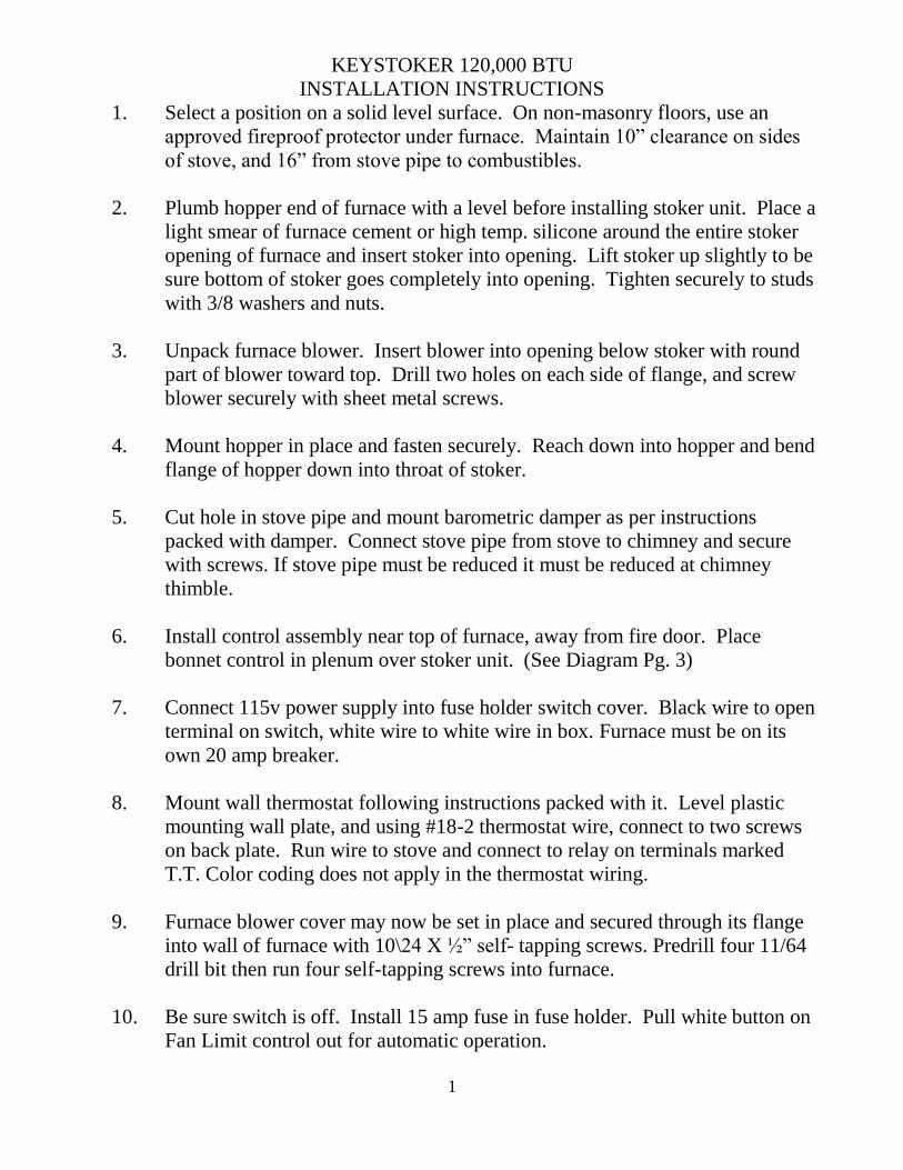
1. Select a position on a solid level surface. On non-masonry floors, use an
approved fireproof protector under furnace. Maintain 10” clearance on sides
of stove, and 16” from stove pipe to combustibles.
2. Plumb hopper end of furnace with a level before installing stoker unit. Place a
light smear of furnace cement or high temp. silicone around the entire stoker
opening of furnace and insert stoker into opening. Lift stoker up slightly to be
sure bottom of stoker goes completely into opening. Tighten securely to studs
with 3/8 washers and nuts.
3. Unpack furnace blower. Insert blower into opening below stoker with round
part of blower toward top. Drill two holes on each side of flange, and screw
blower securely with sheet metal screws.
4. Mount hopper in place and fasten securely. Reach down into hopper and bend
flange of hopper down into throat of stoker.
5. Cut hole in stove pipe and mount barometric damper as per instructions
packed with damper. Connect stove pipe from stove to chimney and secure
with screws. If stove pipe must be reduced it must be reduced at chimney
thimble.
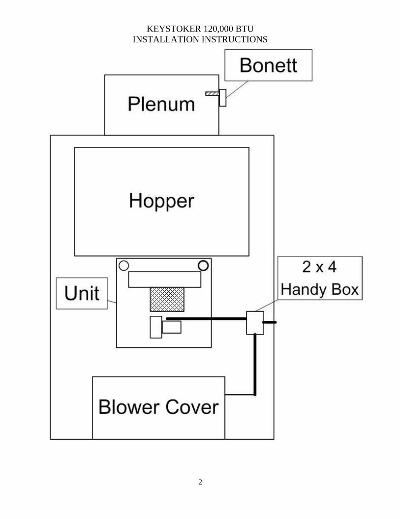
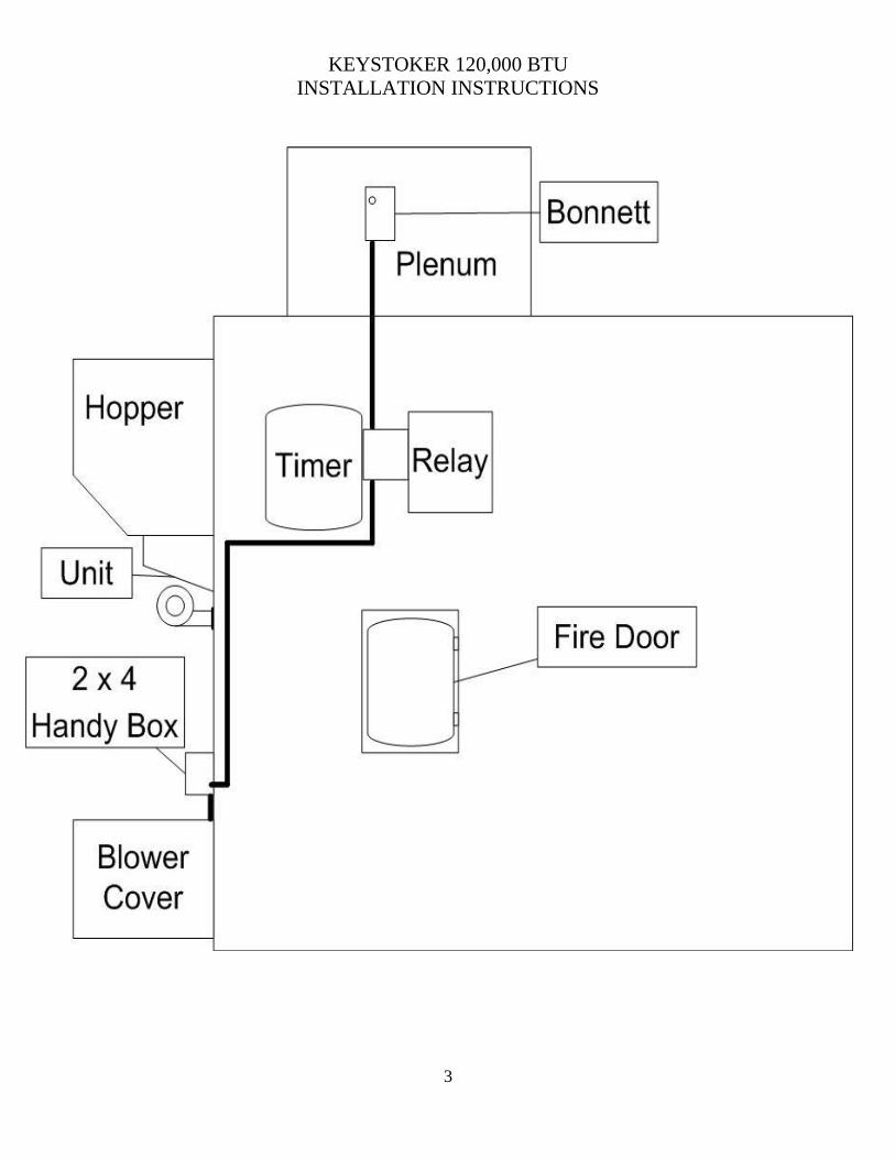
6. Install control assembly near top of furnace, away from fire door. Place
bonnet control in plenum over stoker unit. (See Diagram Pg. 3)
7. Connect 115v power supply into fuse holder switch cover. Black wire to open
terminal on switch, white wire to white wire in box. Furnace must be on its
own 20 amp breaker.
8. Mount wall thermostat following instructions packed with it. Level plastic
mounting wall plate, and using #18-2 thermostat wire, connect to two screws
on back plate. Run wire to stove and connect to relay on terminals marked
T.T. Color coding does not apply in the thermostat wiring.
9. Furnace blower cover may now be set in place and secured through its flange
into wall of furnace with 10\24 X ½” self- tapping screws. Predrill four 11/64
drill bit then run four self-tapping screws into furnace.
10. Be sure switch is off. Install 15 amp fuse in fuse holder. Pull white button on
Fan Limit control out for automatic operation.
KEYSTOKER 120,000 BTU
INSTALLATION INSTRUCTIONS
2
KEYSTOKER 120,000 BTU
INSTALLATION INSTRUCTIONS
3
KEYSTOKER 120,000 BTU
INSTALLATION INSTRUCTIONS
4
Starting initial fire: Fill hopper with coal, reach in through fire door and pull coal
down to cover entire grate area. Place charcoal into a full sheet of newspaper, crumble
paper, and dig charcoal deep into coal in the center of grate. Light newspaper with a
match and turn power switch on. NEVER USE GASOLINE, LITTER FLUID,
KEROSINE, OR ETC. TO START THE FIRE.
NOTE: The coal feeder adjustment nut is PRESET and may not need to be changed.
If it becomes necessary to adjust coal feed, the white nut on the stoker may be turned
CLOCKWISE for MORE coal feed and COUNTER-CLOCKWISE for LESS coal feed.
NEVER USE A WRENCH ON COAL FEED ADJUSTMENT NUT (FINGERS
ONLY).
Should fire ever have to be re-started, no further adjustments to coal feed are necessary.
CHECK DRAFT- After starting a fire and a good fire is established, the chimney will
be warm enough to check draft. Poke the insulation out of the predrilled hole in the
upper left hand of the furnace fire door. Then insert draft gauge into hole in fire door.
The draft should be a (-.02) over fire (stoker unit running hard).The air shutter and/or
the barometric damper on the stove pipe may be used to obtain proper draft readings.
If draft goes above a (-.03) adjust barometric damper to open a little wider.
If draft goes below a (-.02) close the air shutter on combustion motor.
Clean stack and heat exchanger twice during heating season. Reach through fire door or
ash door and brush fly ash from connector pipe between furnace and heat exchanger.
Remove pipe outlet on rear of furnace and with a vacuum, remove fly ash that has
gathered in bottom of heat exchanger. Remove fly ash from under grate yearly, by
removing combustion motor and vacuuming under grate. Lubricate combustion fan and
convection fan motors as per instructions on labels.
KEYSTOKER 120,000 BTU
INSTALLATION INSTRUCTIONS
5
CONTROLS AND THEIR FUNCTIONS
Thermostat: Top pointer is desired room temperature. Bottom pointer is thermostat.
When room temperature drops below setting, combustion blower and gear motor will
start. When room temperature rises, gear motor will stop (see diagram pg. 10).
Relay: Converts 115v to 24v for thermostat, and sends signal to gear motor to start or
stop.
Convection Blower: Located behind enclosure on the left of stove. Blows heated air
into the room. It is energized by the fan and limit control.
Fan & Limit Control: Serves dual purpose. 1. As a high limit, will shut off the stoker
unit to prevent overheating. If internal stove temperature reaches 200 degrees, control
will shut off stoker unit, until temperature drops, which will then allow stoker unit to be
reactivated. 2. As a convection blower control, it starts the convection blower when
internal stove temperature reaches center pointer setting. The convection blower will
run as long as stove remains hot. When stove begins to cool down to low setting on
control, the convection blower will shut off. Normal settings for control are: High limit
(pointer on right) 200 degrees. Center pointer (fan on) 160 degrees. Left pointer (fan
off) 120 degrees. White button in control must be pulled out for normal automatic
operation (see diagram pg. 10 & 11).
Gear Motor: Function is to drive feed mechanism (pusher bar) to slide coal from
hopper onto the grate, to move the fire forward and the ash into the receptacle (see
diagram pg.7)
Combustion Motor: To force air through stoker unit to burn coal (see diagram pg.8).
Timer: Will activate gear motor on stoker unit, to maintain a fire during periods when
no demand is made by thermostat (see diagram pg. 8 & 9).
KEYSTOKER 120,000 BTU
INSTALLATION INSTRUCTIONS
6
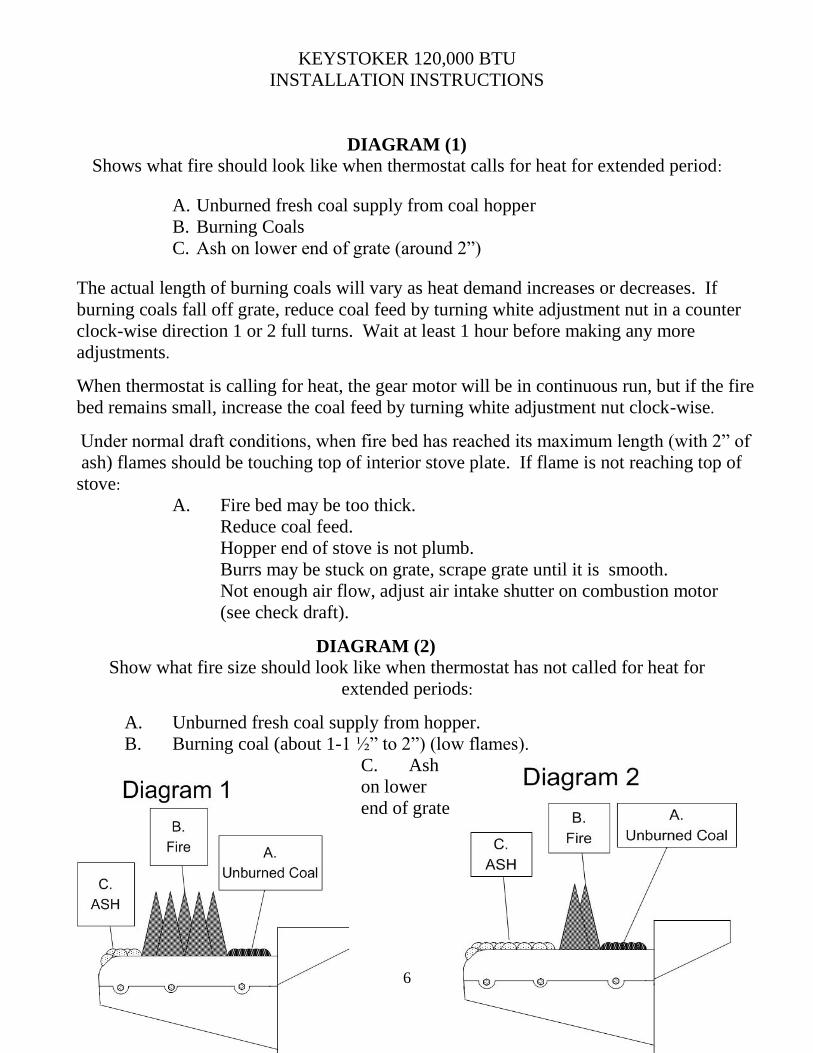
DIAGRAM (1)
Shows what fire should look like when thermostat calls for heat for extended period:
A. Unburned fresh coal supply from coal hopper
B. Burning Coals
C. Ash on lower end of grate (around 2”)
The actual length of burning coals will vary as heat demand increases or decreases. If
burning coals fall off grate, reduce coal feed by turning white adjustment nut in a counter
clock-wise direction 1 or 2 full turns. Wait at least 1 hour before making any more
adjustments.
When thermostat is calling for heat, the gear motor will be in continuous run, but if the fire
bed remains small, increase the coal feed by turning white adjustment nut clock-wise.
Under normal draft conditions, when fire bed has reached its maximum length (with 2” of
ash) flames should be touching top of interior stove plate. If flame is not reaching top of
stove:
A. Fire bed may be too thick.
Reduce coal feed.
Hopper end of stove is not plumb.
Burrs may be stuck on grate, scrape grate until it is smooth.
Not enough air flow, adjust air intake shutter on combustion motor
(see check draft).
DIAGRAM (2)
Show what fire size should look like when thermostat has not called for heat for
extended periods:
A. Unburned fresh coal supply from hopper.
B. Burning coal (about 1-1 ½” to 2”) (low flames).
C. Ash
on lower
end of grate
KEYSTOKER 120,000 BTU
INSTALLATION INSTRUCTIONS
7
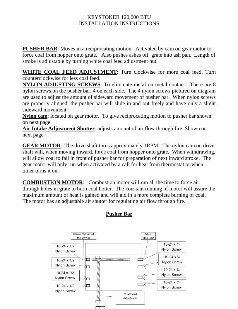
PUSHER BAR: Moves in a reciprocating motion. Activated by cam on gear motor to
force coal from hopper onto grate. Also pushes ashes off grate into ash pan. Length of
stroke is adjustable by turning white coal feed adjustment nut.
WHITE COAL FEED ADJUSTMENT: Turn clockwise for more coal feed, Turn
counterclockwise for less coal feed.
NYLON ADJUSTING SCREWS: To eliminate metal on metal contact. There are 8
nylon screws on the pusher bar, 4 on each side. The 4 nylon screws pictured on diagram
are used to adjust the amount of sideward movement of pusher bar. When nylon screws
are properly aligned, the pusher bar will slide in and out freely and have only a slight
sideward movement.
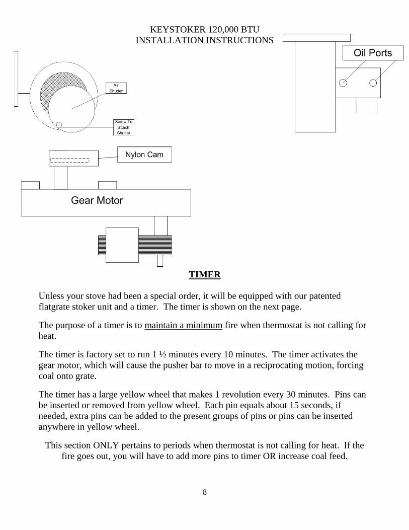
Nylon cam: located on gear motor. To give reciprocating motion to pusher bar shown
on next page
Air Intake Adjustment Shutter: adjusts amount of air flow through fire. Shown on
next page
GEAR MOTOR: The drive shaft turns approximately 1RPM. The nylon cam on drive
shaft will, when moving inward, force coal from hopper onto grate. When withdrawing,
will allow coal to fall in front of pusher bar for preparation of next inward stroke. The
gear motor will only run when activated by a call for heat from thermostat or when
timer turns it on.
COMBUSTION MOTOR: Combustion motor will run all the time to force air
through holes in grate to burn coal hotter. The constant running of motor will assure the
maximum amount of heat is gained and will aid in a more complete burning of coal.
The motor has an adjustable air shutter for regulating air flow through fire.
Pusher Bar
KEYSTOKER 120,000 BTU
INSTALLATION INSTRUCTIONS
8
TIMER
Unless your stove had been a special order, it will be equipped with our patented
flatgrate stoker unit and a timer. The timer is shown on the next page.
The purpose of a timer is to maintain a minimum fire when thermostat is not calling for
heat.
The timer is factory set to run 1 ½ minutes every 10 minutes. The timer activates the
gear motor, which will cause the pusher bar to move in a reciprocating motion, forcing
coal onto grate.
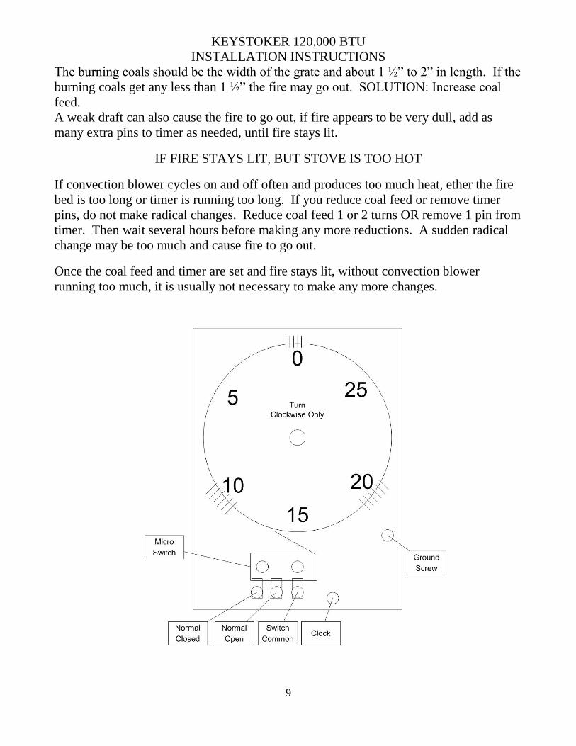
The timer has a large yellow wheel that makes 1 revolution every 30 minutes. Pins can
be inserted or removed from yellow wheel. Each pin equals about 15 seconds, if
needed, extra pins can be added to the present groups of pins or pins can be inserted
anywhere in yellow wheel.
This section ONLY pertains to periods when thermostat is not calling for heat. If the
fire goes out, you will have to add more pins to timer OR increase coal feed.
KEYSTOKER 120,000 BTU
INSTALLATION INSTRUCTIONS
9
The burning coals should be the width of the grate and about 1 ½” to 2” in length. If the
burning coals get any less than 1 ½” the fire may go out. SOLUTION: Increase coal
feed.
A weak draft can also cause the fire to go out, if fire appears to be very dull, add as
many extra pins to timer as needed, until fire stays lit.
IF FIRE STAYS LIT, BUT STOVE IS TOO HOT
If convection blower cycles on and off often and produces too much heat, ether the fire
bed is too long or timer is running too long. If you reduce coal feed or remove timer
pins, do not make radical changes. Reduce coal feed 1 or 2 turns OR remove 1 pin from
timer. Then wait several hours before making any more reductions. A sudden radical
change may be too much and cause fire to go out.
Once the coal feed and timer are set and fire stays lit, without convection blower
running too much, it is usually not necessary to make any more changes.
KEYSTOKER 120,000 BTU
INSTALLATION INSTRUCTIONS
10
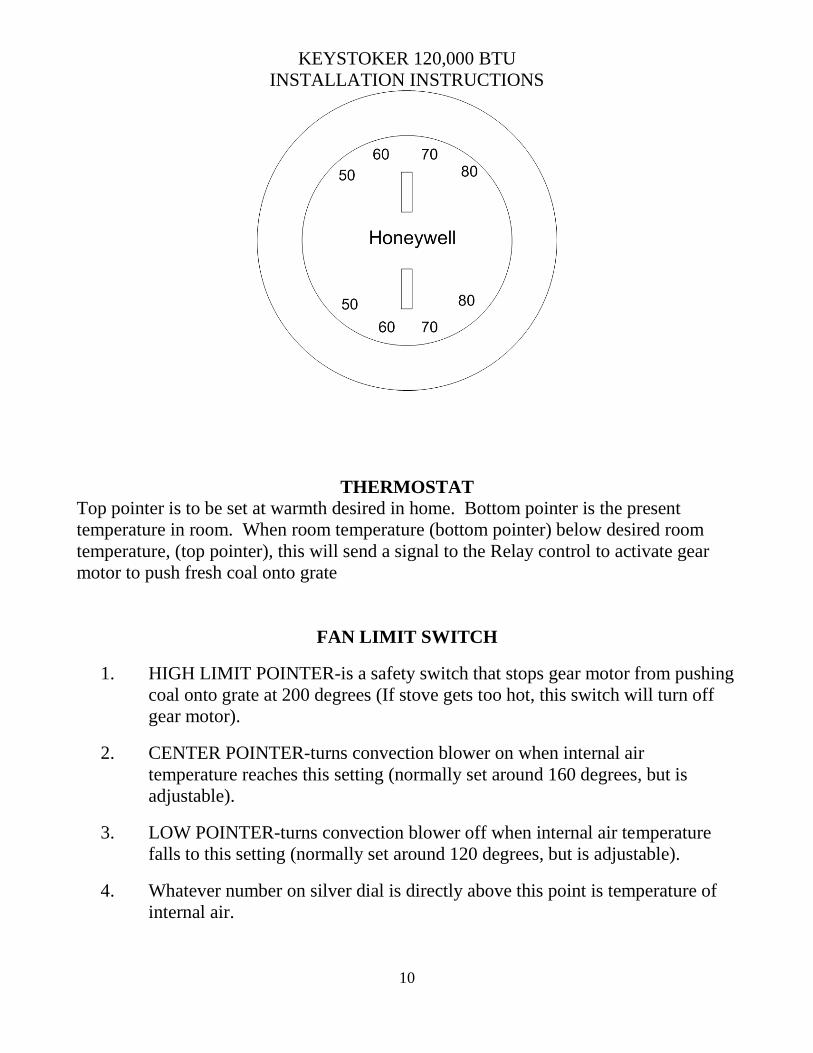
THERMOSTAT Top pointer is to be set at warmth desired in home. Bottom pointer is the present
temperature in room. When room temperature (bottom pointer) below desired room
temperature, (top pointer), this will send a signal to the Relay control to activate gear
motor to push fresh coal onto grate
FAN LIMIT SWITCH
1. HIGH LIMIT POINTER-is a safety switch that stops gear motor from pushing
coal onto grate at 200 degrees (If stove gets too hot, this switch will turn off
gear motor).
2. CENTER POINTER-turns convection blower on when internal air
temperature reaches this setting (normally set around 160 degrees, but is
adjustable).
3. LOW POINTER-turns convection blower off when internal air temperature
falls to this setting (normally set around 120 degrees, but is adjustable).
4. Whatever number on silver dial is directly above this point is temperature of
internal air.
KEYSTOKER 120,000 BTU
INSTALLATION INSTRUCTIONS
11
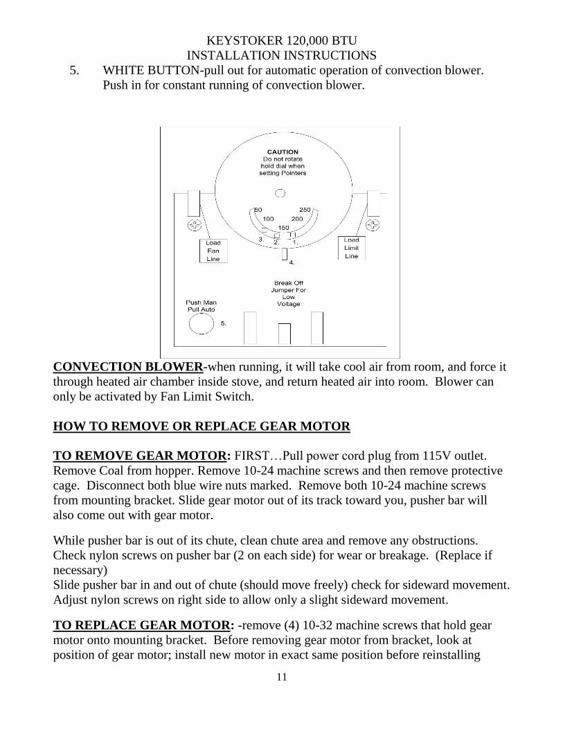
5. WHITE BUTTON-pull out for automatic operation of convection blower.
Push in for constant running of convection blower.
CONVECTION BLOWER-when running, it will take cool air from room, and force it
through heated air chamber inside stove, and return heated air into room. Blower can
only be activated by Fan Limit Switch.
HOW TO REMOVE OR REPLACE GEAR MOTOR
TO REMOVE GEAR MOTOR: FIRST…Pull power cord plug from 115V outlet.
Remove Coal from hopper. Remove 10-24 machine screws and then remove protective
cage. Disconnect both blue wire nuts marked. Remove both 10-24 machine screws
from mounting bracket. Slide gear motor out of its track toward you, pusher bar will
also come out with gear motor.
While pusher bar is out of its chute, clean chute area and remove any obstructions.
Check nylon screws on pusher bar (2 on each side) for wear or breakage. (Replace if
necessary)
Slide pusher bar in and out of chute (should move freely) check for sideward movement.
Adjust nylon screws on right side to allow only a slight sideward movement.
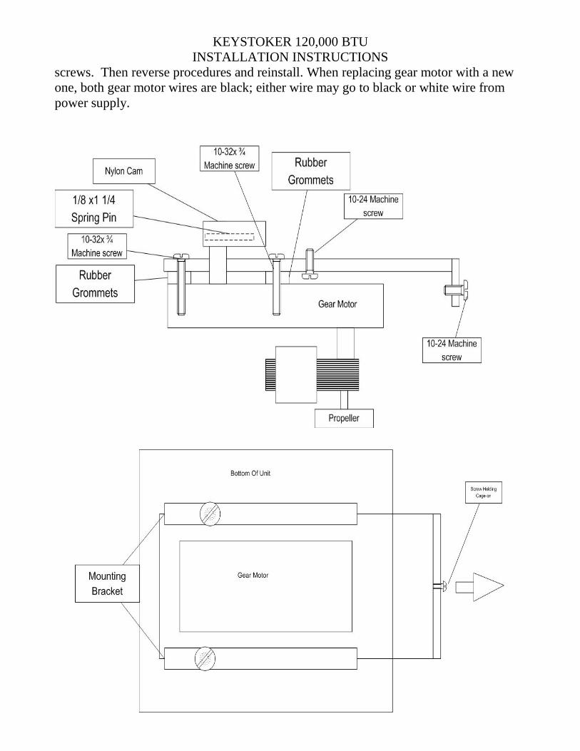
TO REPLACE GEAR MOTOR: -remove (4) 10-32 machine screws that hold gear
motor onto mounting bracket. Before removing gear motor from bracket, look at
position of gear motor; install new motor in exact same position before reinstalling
KEYSTOKER 120,000 BTU
INSTALLATION INSTRUCTIONS
12
screws. Then reverse procedures and reinstall. When replacing gear motor with a new
one, both gear motor wires are black; either wire may go to black or white wire from
power supply.
KEYSTOKER 120,000 BTU
INSTALLATION INSTRUCTIONS
13
A-120 WITH THERMOSTAT
FIRE GOES OUT See page 8 and 9 (Timer) and Page 6 Diagram (2)
COAL KLINKERING OR FUSING TOGETHER See page 6 Diagram (1) & (2)
SULFUR SMELL See page 4 (Cleaning & Lubrication and check draft section)
STOKER UNIT DOESN’T FEED COAL See page 7 (Pusher Bar)
PUSHER BAR IS NOT MOVING STRAIGHT See page 7 (Pusher Bar)
CONVECTION BLOWER RUNS TOO OFTEN See Pages 9 and 10
CONVECTION BLOWER RUNS CONSTANTLY Pull white button on Fan Limit
Switch out for automatic operation. Clean screen and fan blades on blower. See page 11
THERMOSTAT CALLS FOR HEAT, but CONVECTION BLOWER OFF TOO
LONG See Page 6 Diagram (1)
FIRE IS LIT, BUT NOT ENOUGH HEAT
If gear motor only runs short cycles, timer is working. When thermostat calls for
heat, gear motor should run steady. If gear motor is running steady, but fire is small,
increase coal feed. (See pages 6 & 7).
If gear motor is not running steady, check for loose wire in Thermostat or in
Relay. Check for broken thermostat wire between thermostat and Relay.
GEAR MOTOR RUNS CONSTANTLY MAKING TOO MUCH HEAT
Gear motor can only be activated by thermostat or timer. Remove thermostat
wires from T.T. terminals in Relay, if gear motor shuts off, replace thermostat wire or
Thermostat. Check timer to see if yellow wheel is turning, if not replace timer motor.
Check timer switch. (See page 8 and 9 Timer)
CONVECTION BLOWER NOT BLOWING MUCH AIR Clean screen and fan blades
on blower.
GEAR MOTOR SHUTS OFF ON HI-LIMIT
KEYSTOKER 120,000 BTU
INSTALLATION INSTRUCTIONS
14
High Limit pointer in Fan Limit Switch is designated to shut gear motor off when
internal air temperature reaches 200 degrees. If internal air temperature stays on 200
degrees, Convection Blower is not cooling stove off quickly enough. Clean screen and
fan blades on blower or replace convection blower (or See Page 10 & 11, Fan Limit
Control).
BIG FIRE BUT NOT MUCH HEAT
Fan blades on combustion motor dirty. Brush off. Accumulated fly ash under
grate. Remove combustion motor and clean under grate.
Holes blocked in grate. Open holes with 1/8 center punch (See Page 6 Diagram (1).
TO CLEAN UNDER OR REPLACE GRATE See Page 6 (Cleaning & Lubrication)
NYLON CAM MELTS
Under normal operating conditions, nylon cam will not melt. Melting of nylon cam can
only be caused by a draft problem.
A blockage in chimney, chimney connector, stove pipe, or stove. Inspect and clean.
Or excessive draft, caused by high chimney, large flue, or high winds. Clean and adjust
barometric damper. (Set barometric damper with a draft gauge to obtain a draft reading
of -.02 , See Page 4 Draft Check)
TO ORDER PARTS
Find the metal 1 ½” x 3” Keystoker label fastened to stoker unit body, near gear motor.
The four or five digit number will be required to get proper replacement parts from your
dealer.
Pusher Bar: Activated by cam on gear motor to force coal from hopper onto grate,
forcing ashes to fall into ash pan. Length of stroke is adjustable.
1. White coal feed adjustment nut-Turn clockwise for more coal feed. Turn
counter-clockwise for less coal feed.
2. Nylon adjusting screws- To eliminate metal to metal contact during coal
feeding process.
3. Nylon cam-To give reciprocating movement to pusher bar.
Gear motor: The drive shaft turns approximately 1 RPM. The nylon cam on drive shaft
will (when moving forward) force coal down from hopper onto grate. When
withdrawing will allow coal to fall in front of pusher bar for next inward stroke.
KEYSTOKER 120,000 BTU
INSTALLATION INSTRUCTIONS
15
Combustion Motor: Combustion motor is forcing air through fire to burn coal hotter
and faster. Combustion motor runs all the time.
4. Oil motors every six months with light grade of S.A.E. motor oil.
Insert 3 sets of 6 timer clips in timer.
Feed power to switch 1 and 2.
Pin shutter on combustion motor at ½ open
Turn coal feed clockwise to max and back off 4 turns.
Convection blower runs too often
A. Convection blower will only run when internal air temperature reaches center
pointer of fan limit switch. If blower runs too often during periods of no
demand by thermostat, internal air temperature is too high. To cool stove off,
decrease coal feed 1 or 2 turns. If stove had timer, remove one clip in each
group. Make adjustments little at a time.
Convection blower runs constantly
A. Pull white button on fan limit switch out for automatic operation.
Convection blower off too long
A. Convection blower will only turn or when internal air temperature reaches
center pointer in fan limit switch.
1 . Fire bed is too small-increase coal feed until only two inches of ash
remain on bottom of grate.
2. Fire bed is not burning hot-Clean under grate. Clean combustion fan.
Fire lit but no heat
If stoker unit only runs short cycles:
A. Loose or broken wires from thermostat to Honeywell Relay. Check connections
on thermostat back plate to thermostat. If bottom two screws are loose,
thermostat will not operate stoker.
Stoker unit runs constantly
Stoker unit can only run by demand of thermostat or timer.
A. Disconnect wires from thermostat-if stoker shuts off, replace thermostat or
thermostat wire.
KEYSTOKER 120,000 BTU
INSTALLATION INSTRUCTIONS
16
Convection blower not blowing hard
A. Clean screen and fan blades on convection blower.
Stoker unit shuts off on Hi-limit
High limit pointer in fan limit switch is designed to shut stoker unit off, when internal
air temperature reaches safety setting of 200 degrees. If internal air temperature stays
on high reading, convection blower is not cooling stove off quickly enough. Clean
screen on convection blower, fan blades on convection blower, or air filters.
Not enough air through fire
A. Fan blades on combustion motor dirty. Brush off.
B. Accumulated fly ash under grate. Remove combustion motor and clear.
C. Holes blocked in grate. Open holes with 1/8” center punch.
D. Combustion motor not running. Replace. To replace combustion motor, remove
three nuts, disconnect wires, and install new motor.
To replace grate
Remove all coal from hopper and stoker unit. Remove nut and bolt from bottom of
grate. Tap grate in an upward direction with hammer, remove grate, clean off old
furnace cement from grate and unit. Clean fly ash from under grate. Smear furnace
cement around top of grate and sides of grate down to where the holes start. Place grate
back into unit, and secure with nut and bolt.
Nylon cam melts
Under normal operating conditions, nylon cam will not melt. Melting of nylon cam can
only be caused by draft.
A. A blockage in chimney, chimney connector, stove pipe, or stove. Inspect and
clean.
B. Excessive draft caused by high chimney, large flue, or high winds. Clean and
adjust barometric damper. (Set barometric damper with a draft gauge) To set
barometric damper with draft gage: start fire; allow stove and chimney to warm
up. Check draft through ¼” hole in fire door. Insert draft gauge in hole, and
adjust barometric damper to obtain a draft reading of -.02 at full fire.
To order parts
Should it become necessary to order a control, identify the number marked on the
control before ordering. Controls are warranted for one year. The controls are date
coded, the first two numbers indicate the year, second two numbers indicate week of
year. Save your sales receipt as PROOF OF PURCHASE.
KEYSTOKER 120,000 BTU
INSTALLATION INSTRUCTIONS
17
If you need to order a part on stoker unit, find the 1” x 3” Keystoker label fastened to
stoker unit body. The four or five digit number will be required to get proper
replacement parts from your dealer.
Stoker unit doesn’t feed coal
A. Pusher bar may be jammed. Remove all coal from hopper and stoker unit. Work
pusher bar inward and outward, not sideways. Pusher bar is free when it has a
slight inward and outward movement.
B. Gear motor is defective. Replace. Remove screw from black expanded metal
cover. Disconnect wires on gear motor. Remove two screws from gear motor
mounting bracket, place hand on gear motor, pull motor toward you. Remove
old gear motor from mounting bracket; install new gear motor on mounting
bracket. Place cam into hole in pusher bar, slide assembly in stoker unit.
Tighten screws and reconnect wires.
SAFETY
THE BURNING OF FOSSIL FUELS GENERATES CARBON MONOXIDE
GASES. CARBON MONOXIDE GASES ARE TOXIC, CAN CAUSE
SICKNESS, AND CAN BE FATAL.
To prevent toxic carbon monoxide gases from entering the home, certain precautions
must be taken.
Ash tub must be emptied on a regular basis to prevent ashes from overflowing into
ash pit area. Excessive ash accumulation may impede air flow to the chimney,
preventing gases to be drawn up chimney.
Fire Door and Ash doors must be closed at all times during normal operation.
It is necessary to keep some coal in hopper while stove is in operation.
In most applications it is sufficient to clean stove and stove pipe twice during the
heating season. However, under extreme weather conditions or by high demand on
stove running periods, the stove and stove pipe may need more frequent cleaning.
Clean as often as necessary.
CAUTION ASH PAN IS HOT! ALWAYS WEAR GLOVES TO REMOVE ASH PAN…
KEYSTOKER 120,000 BTU
INSTALLATION INSTRUCTIONS
18
Before removing ash pan, turn switch off or pull power cord plug from 110 volt outlet.
Open ash door. Use a good pair of gloves to remove ash pan. Place ash pan on non-
combustible surface. Slide an empty ash pan into stove. Close ash door. Turn switch on
or plug power cord back into 110 V outlet.
ON DIRECT VENT MODELS
After removing ash pan, using long brush supplied with stove, reach brush straight
back into 6” exhaust pipe and with a circular motion, sweep brush around inside pipe.
Sweep excess toward bottom of stove and remove or vacuum dust out of stove. This
procedure may only be required once or twice a month during heating season. Place
empty ash pan into stove and turn switch or plug power cord into 110 V outlet.
Fan blade and fan blade chamber may have to be cleaned several times during the
heating season (refer to cleaning instructions).
The 4” exhaust pipe going through outside wall of home should also be cleaned when
fan chamber is being cleaned.
If 4” exhaust pipe is not going straight out through outside wall and 4” pipe is in a
vertical position to access an area above outside grade, the 4” elbow is a likely
location for dust to accumulate and restrict exhaust air flow to outside of home. A 4”
tee may also be used in place of a 4” elbow. This will allow the bottom of the tee to
be used as a collection point (out of the flow of exhaust gases) providing an easier
access for cleaning and less chance for restriction or blockage.
IT IS ESSENTIAL that every 4” pipe joint or connection be sealed with a high
temperature silicone or equivalent. All adjustable joints on elbows must also be sealed
with silicone. FAILURE TO SEAL ALL JOINTS could allow carbon monoxide to
leak into the home.
KEYSTOKER 120,000 BTU
INSTALLATION INSTRUCTIONS
19
KEYSTOKER 120,000 BTU
INSTALLATION INSTRUCTIONS
20
Keystone Manufacturing Company extends the following warranties to the original owner from the
date of purchase.
Five Years Workmanship on stove body
Two years on grates and side rails
One year all electric controls and motors.
Warranty does not apply if damage occurs because of improper handling, operation, abuse, rust,
corrosion, misuse or use beyond rated capacity.
This warranty does not apply if the product has been altered in any way after leaving the factory.
All warranty claims should be made through dealer where the appliance was originally purchased.
Model, Stoker Unit Number 1 ½ x 3 tag (found below hopper) and original copy of the sales receipt
need be presented to dealer.
If a consumer chooses to make a warranty claim directly through Keystone Manufacturing Company
model, stoker unit number, and copy of the original sales receipt are required. Customer must provide
a credit card which will be charged for the full retail price for the product plus shipping and handling.
When defective part is returned to the company and found to be a defect within warranty period the
consumer’s credit card will be credited back the cost of part.
Keystone Manufacturing Company assumes no responsibility for any labor expanses, for service,
product removal, reinstallation or any freight charges for parts returned to the company.
If defective in material or workmanship and if removed by the owner with in warranty period Keystone
manufacturing will at their opinion repair or replace the product.
This warranty is limited to defective parts, repair, or replacement at our opinion and excludes any
incidental and consequential damages connected there with.
Warranty exclusions, labor, glass, door gasket, ash tub, hopper and paint
Furnace Information
Dealer_________________________________________
Date of purchase_________________________________
Stoker unit number_______________________________
Stove Model_____________________________________
KEYSTOKER 120,000 BTU
INSTALLATION INSTRUCTIONS
21
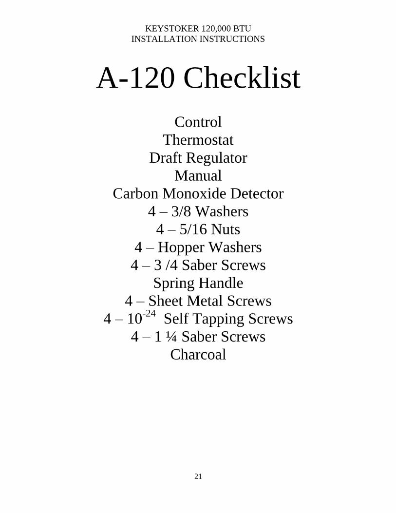
A-120 Checklist
Control
Thermostat
Draft Regulator
Manual
Carbon Monoxide Detector
4 – 3/8 Washers
4 – 5/16 Nuts
4 – Hopper Washers
4 – 3 /4 Saber Screws
Spring Handle
4 – Sheet Metal Screws
4 – 10-24
Self Tapping Screws
4 – 1 ¼ Saber Screws
Charcoal