Embed Size (px)
Citation preview
The Formwork Experts
07/2008 Ü
UK999787002
User information
Method statement
Dokaflex 1-2-4
9720-337-01

2 999787002 - 07/2008 Ü
User information Dokaflex 1-2-4
The Formwork Experts
© by Doka Industrie GmbH, A-3300 Amstetten
3999787002 - 07/2008 Ü
Contents Page
User information Dokaflex 1-2-4
The Formwork Experts
Elementary safety warnings ........................................................................ 4Eurocodes at Doka........................................................................................ 6Product description ...................................................................................... 8System logic for all floor-slabs up to 30 cm thick....................................11Instructions for assembly and use ............................................................ 12Adaptability .................................................................................................18System components of Dokaflex 1-2-4– also for slab thicknesses of over 30 cm .................................................19Floor formwork around edges...................................................................20Safety on the structure...............................................................................21Beam forming support ...............................................................................22Drop-beam not integrated into the floor-slab / stop-end formwork.......23Drop-beam integrated into the floor-slab.................................................24Slab stop-ends ............................................................................................26Combining Doka table systems.................................................................27Transporting, stacking and storing ...........................................................28Reshoring props, concrete technology and striking................................30Formwork planning with Tipos .................................................................32Doka service offerings................................................................................33
Component overview.................................................................................34
4 999787002 - 07/2008 Ü
User information Dokaflex 1-2-4
The Formwork Experts
Elementary safety warnings
User target groups
● This User Information booklet (Method State-ment) is aimed at everyone who will be working with the Doka product or system it describes. It contains information on how to set up this sys-tem, and on correct, compliant utilisation of the system.
● All persons working with the product described herein must be familiar with the contents of this manual and with all the safety instructions it con-tains.
● Persons who are incapable of reading and under-standing this booklet, or who can do so only with difficulty, must be instructed and trained by the customer.
● The customer is to ensure that the information materials provided by Doka (e.g. User Informa-tion booklets, Instructions for Assembly and Use, Operating Instruction manuals, plans etc.) are available to all users, and that they have been made aware of them and have easy access to them at the usage location.
Remarks on this document
● This User Information booklet can also be used as a generic method statement or incorporated with a site-specific method statement.
● Many of the illustrations in this booklet show the situation during formwork assembly and are therefore not always complete from the safety point of view.
● Further safety instructions, especially warnings, will be found in the individual sections of this document!
Planning
● Provide safe workplaces for those using the formwork (e.g. for when it is being erected/dis-mantled, modified or repositioned etc). It must be possible to get to and from these workplaces via safe access routes!
● If you are considering any deviation from the details and instructions given in this booklet, or any application which goes beyond those described in the booklet, then revised static cal-culations must be produced for checking, as well as supplementary assembly instructions.
Rules applying during all phases of
the assignment:
● The customer must ensure that this product is erected and dismantled, reset and generally used for its intended purpose under the direction and supervision of suitably skilled persons with the authority to issue instructions.
● Doka products are ONLY to be used in accord-ance with the Doka User Information booklets or other technical documentation provided by Doka.
● The stability of all components and units must be ensured during all phases of the construction work!
● The functional/technical instructions, safety warnings and loading data must all be strictly observed and complied with. Failure to do so can cause accidents and severe (even life-threaten-ing) damage to health, as well as very great material damage.
● Fire-sources are not permitted anywhere near the formwork. Heating appliances are only allowed if properly and expertly used, and set up a safe distance away from the formwork.
● The work must take account of the weather con-ditions (e.g. risk of slippage). In extreme weather, steps must be taken in good time to safeguard the equipment, and the immediate vicinity of the equipment, and to protect employees.
● All connections must be checked regularly to ensure that they still fit properly and are function-ing correctly.It is very important to check all screw-type con-nections and wedge-clamped joins whenever the construction operations require (particularly after exceptional events such as storms), and to tighten them if necessary.
Assembly
● The equipment/system must be inspected by the customer before use, to ensure that it is in suita-ble condition. Steps must be taken to rule out the use of any components that are damaged, deformed, or weakened due to wear, corrosion or rot.
● Combining our formwork systems with those of other manufacturers could be dangerous, risking damage to both health and property. If you intend to combine different systems, please con-tact Doka for advice first.
● The assembly work must be carried out by suita-bly qualified employees of the client's.
User information Dokaflex 1-2-4
5999787002 - 07/2008 Ü The Formwork Experts
Erecting the formwork
● Doka products and systems must be set up in such a way that all loads acting upon them are safely transferred!
Pouring
● Do not exceed the permitted fresh-concrete pres-sures. Excessively high pouring rates lead to formwork overload, cause greater deflection and risk causing breakage.
Striking the formwork
● Do not strike the formwork until the concrete has reached sufficient strength and the person in charge has given the order for the formwork to be struck!
● When striking the formwork, never use the crane to break concrete cohesion. Use suitable tools such as timber wedges, special pry-bars or sys-tem features such as Framax stripping corners.
● When striking the formwork, do not endanger the stability of any part of the structure, or of any scaffolding, platforms or formwork that is still in place!
Transporting, stacking and storing
● Observe all regulations applying to the handling of formwork and scaffolding. In addition, the Doka slinging means must be used - this is a mandatory requirement.
● Remove any loose parts or fix them in place so that they cannot be dislodged or fall free!
● All components must be stored safely, following all the special Doka instructions given in the rele-vant sections of this User Information booklet!
Regulations; industrial safety
● Always observe all industrial safety regulations and other safety rules applying to the application and utilisation of our products in the country and/or region in which you are operating.
Instruction as required by EN 13374:● If a person or object falls against, or into, the
sideguard system and/or any of its accessories, the sideguard component affected may only con-tinue in use after it has been inspected and passed by an expert.
Maintenance
● Only original Doka components may be used as spare parts.
Symbols usedThe following symbols are used in this booklet:
MiscellaneousWe reserve the right to make alterations in the inter-ests of technical progress.Unless otherwise stated, all dimensions are given in cm.
Important note
Failure to observe this may lead to mal-function or damage.
Caution / warning / danger
Failure to observe this may lead to mate-rial damage, and to injury to health which may range up to the severe or even life-threatening.
Instruction
This symbol indicates that actions need to be taken by the user.
Sight-check
Indicates that you need to do a sight-check to make sure that necessary actions have been carried out.
Tip
Points out useful practical tips.
Reference
Refers to other documents and materials.
☞
The Formwork Experts6 999787002 - 07/2008 Ü
User information Dokaflex 1-2-4
Eurocodes at DokaIn Europe, a uniform series of Standards known as Eurocodes (EC) was developed for the construction field by the end of 2007. These are intended to pro-vide a uniform basis, valid throughout Europe, for product specifications, tenders and mathematical verification.The EC are the world's most highly developed Standards in the construction field.In the Doka Group, the EC are to be used as stand-ard from the end of 2008. They will thus supersede
the DIN norms as the "Doka standard" for product design.The widely used "Permissible stress design" (com-paring the actual stresses with the permissible stresses) has been superseded by a new safety con-cept in the EC.The EC contrast the actions (loads) with the resist-ance (capacity). The previous safety factor in the permissible stresses is now divided into several partial factors. The safety level remains the same!
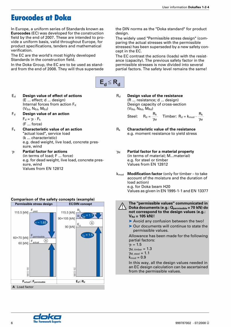
Comparison of the safety concepts (example)
Ed Design value of effect of actions(E ... effect; d ... design)Internal forces from action Fd
(VEd, NEd, MEd)
Rd Design value of the resistance(R ... resistance; d ... design)Design capacity of cross-section(VRd, NRd, MRd)
Fd Design value of an actionSteel: Rd =
Rk Timber: Rd = kmod ·Rk
Fd = γF · Fk γM γM
(F ... force)Fk Characteristic value of an action
"actual load", service load(k ... characteristic)e.g. dead weight, live load, concrete pres-sure, wind
Rk Characteristic value of the resistancee.g. moment resistance to yield stress
γF Partial factor for actions(in terms of load; F ... force)e.g. for dead weight, live load, concrete pres-sure, windValues from EN 12812
γM Partial factor for a material property(in terms of material; M...material)e.g. for steel or timberValues from EN 12812
kmod Modification factor (only for timber – to take account of the moisture and the duration of load action)e.g. for Doka beam H20Values as given in EN 1995-1-1 and EN 13377
Ed
Rd
Permissible stress design EC/DIN concept
Factual≤ Fpermissible Ed≤ Rd
A Load factor
60 [kN]
60<70 [kN]
115.5 [kN]
� ~ 1.65
Fyield
Fpermissible
Factual
9801
3-10
0
A
90 [kN]
115.5 [kN]
90<105 [kN]
Rk
Rd
Ed
�M
= 1.1
�F
= 1.5
9801
3-10
2
A
The "permissible values" communicated in Doka documents (e.g.: Qpermissible = 70 kN) do not correspond to the design values (e.g.: VRd = 105 kN)!
➤ Avoid any confusion between the two!➤ Our documents will continue to state the
permissible values. Allowance has been made for the following partial factors:γF = 1.5γM, timber = 1.3γM, steel = 1.1kmod = 0.9In this way, all the design values needed in an EC design calculation can be ascertained from the permissible values.
User information Dokaflex 1-2-4
7999787002 - 07/2008 Ü The Formwork Experts
Notes

The Formwork Experts8 999787002 - 07/2008 Ü
User information Dokaflex 1-2-4
Product description
Dokaflex 1-2-4 -
the versatile hand-set system for
floor-slabs
Dokaflex 1-2-4 can easily be adapted to fit any lay-out, simply by telescoping the Doka H20 top beams. The materials planning work is done by slide-rule, which appreciably reduces the costs of planning and operations scheduling.● no structural-design work is needed, as 1-2-4
shows you the maximum spacings for all slabs up to 30 cm thick
● you can tell at a glance whether the formwork has been set up correctly
Further advantages:● infill zones are managed within the system, mak-
ing it easy to accommodate walls and columns● for shoring heights of up to 5.50 m● any type of form-facing can be used● no need to measure up
Dokaflex 1-2-4 is ideal for enclosed spaces where the formwork superstructure can rest up against walls on all sides.Horizontal forces at exposed slab-edges, drop beams or steps in ceiling slabs must be restrained by strutting or back-stays.
Small number of system compo-
nents - all perfectly co-ordinated
9720-202-01
A
B
C D
E
F
User information Dokaflex 1-2-4
9999787002 - 07/2008 Ü The Formwork Experts
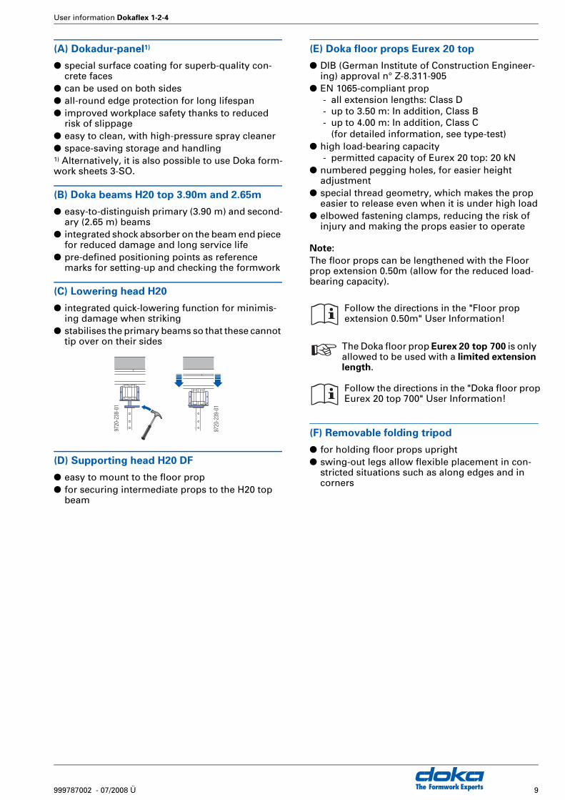
(A) Dokadur-panel1)
● special surface coating for superb-quality con-crete faces
● can be used on both sides● all-round edge protection for long lifespan● improved workplace safety thanks to reduced
risk of slippage● easy to clean, with high-pressure spray cleaner● space-saving storage and handling1) Alternatively, it is also possible to use Doka form-work sheets 3-SO.
(B) Doka beams H20 top 3.90m and 2.65m
● easy-to-distinguish primary (3.90 m) and second-ary (2.65 m) beams
● integrated shock absorber on the beam end piece for reduced damage and long service life
● pre-defined positioning points as reference marks for setting-up and checking the formwork
(C) Lowering head H20
● integrated quick-lowering function for minimis-ing damage when striking
● stabilises the primary beams so that these cannot tip over on their sides
(D) Supporting head H20 DF
● easy to mount to the floor prop● for securing intermediate props to the H20 top
beam
(E) Doka floor props Eurex 20 top
● DIB (German Institute of Construction Engineer-ing) approval n° Z-8.311-905
● EN 1065-compliant prop- all extension lengths: Class D- up to 3.50 m: In addition, Class B- up to 4.00 m: In addition, Class C
(for detailed information, see type-test)● high load-bearing capacity
- permitted capacity of Eurex 20 top: 20 kN● numbered pegging holes, for easier height
adjustment● special thread geometry, which makes the prop
easier to release even when it is under high load● elbowed fastening clamps, reducing the risk of
injury and making the props easier to operate
Note:
The floor props can be lengthened with the Floor prop extension 0.50m (allow for the reduced load-bearing capacity).
(F) Removable folding tripod
● for holding floor props upright● swing-out legs allow flexible placement in con-
stricted situations such as along edges and in corners
9720
-239
-01
9720
-238
-01
Follow the directions in the "Floor prop extension 0.50m" User Information!
☞ The Doka floor prop Eurex 20 top 700 is only allowed to be used with a limited extension length.
Follow the directions in the "Doka floor prop Eurex 20 top 700" User Information!
The Formwork Experts10 999787002 - 07/2008 Ü
User information Dokaflex 1-2-4
Notes
User information Dokaflex 1-2-4
11999787002 - 07/2008 Ü The Formwork Experts
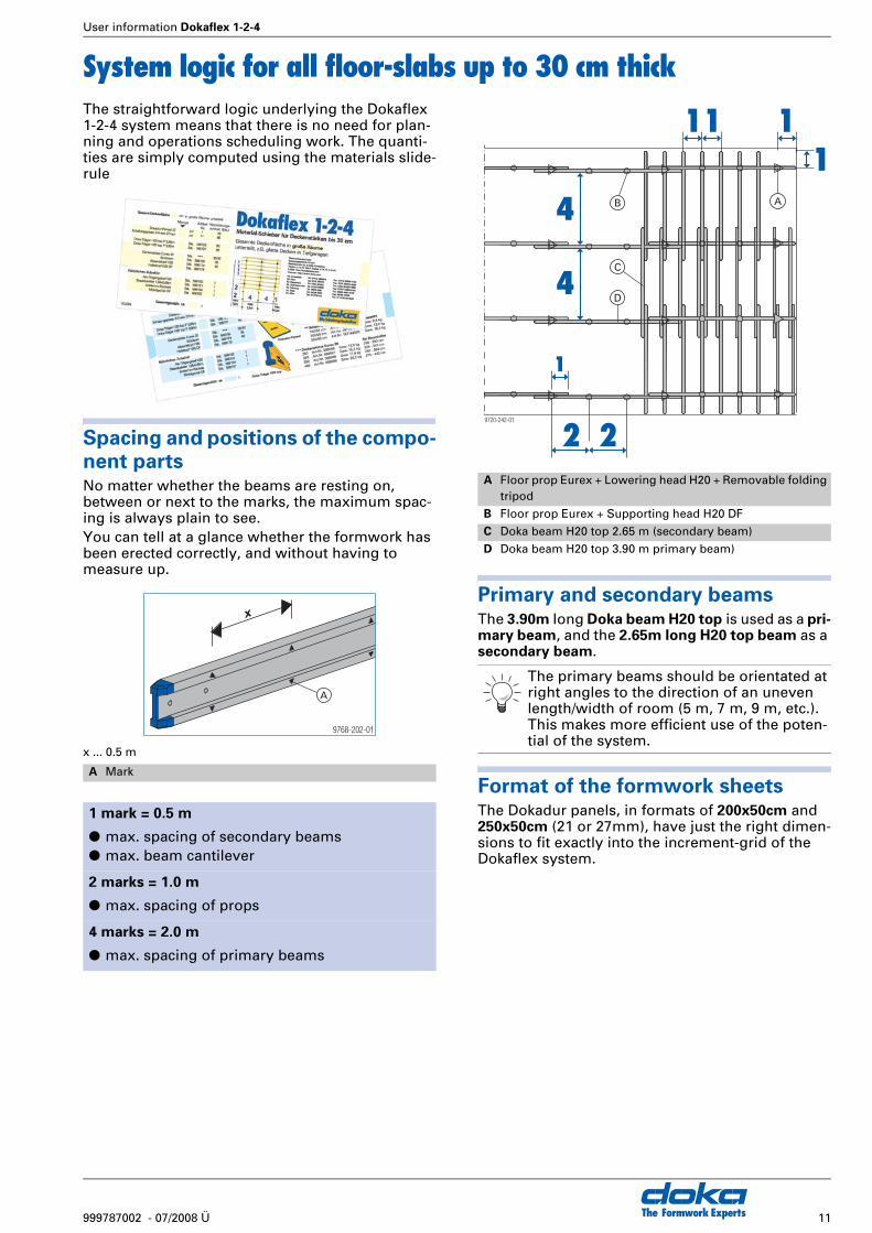
System logic for all floor-slabs up to 30 cm thickThe straightforward logic underlying the Dokaflex 1-2-4 system means that there is no need for plan-ning and operations scheduling work. The quanti-ties are simply computed using the materials slide-rule
Spacing and positions of the compo-nent partsNo matter whether the beams are resting on, between or next to the marks, the maximum spac-ing is always plain to see.You can tell at a glance whether the formwork has been erected correctly, and without having to measure up.
x ... 0.5 m
Primary and secondary beamsThe 3.90m long Doka beam H20 top is used as a pri-mary beam, and the 2.65m long H20 top beam as a secondary beam.
Format of the formwork sheetsThe Dokadur panels, in formats of 200x50cm and 250x50cm (21 or 27mm), have just the right dimen-sions to fit exactly into the increment-grid of the Dokaflex system.
A Mark
1 mark = 0.5 m
● max. spacing of secondary beams● max. beam cantilever
2 marks = 1.0 m
● max. spacing of props
4 marks = 2.0 m
● max. spacing of primary beams
x
9768-202-01
A
A Floor prop Eurex + Lowering head H20 + Removable folding tripod
B Floor prop Eurex + Supporting head H20 DF
C Doka beam H20 top 2.65 m (secondary beam)
D Doka beam H20 top 3.90 m primary beam)
The primary beams should be orientated at right angles to the direction of an uneven length/width of room (5 m, 7 m, 9 m, etc.). This makes more efficient use of the poten-tial of the system.
1
2 2
4
4
1
1
11
9720-242-01
A
C
B
D
The Formwork Experts12 999787002 - 07/2008 Ü
User information Dokaflex 1-2-4
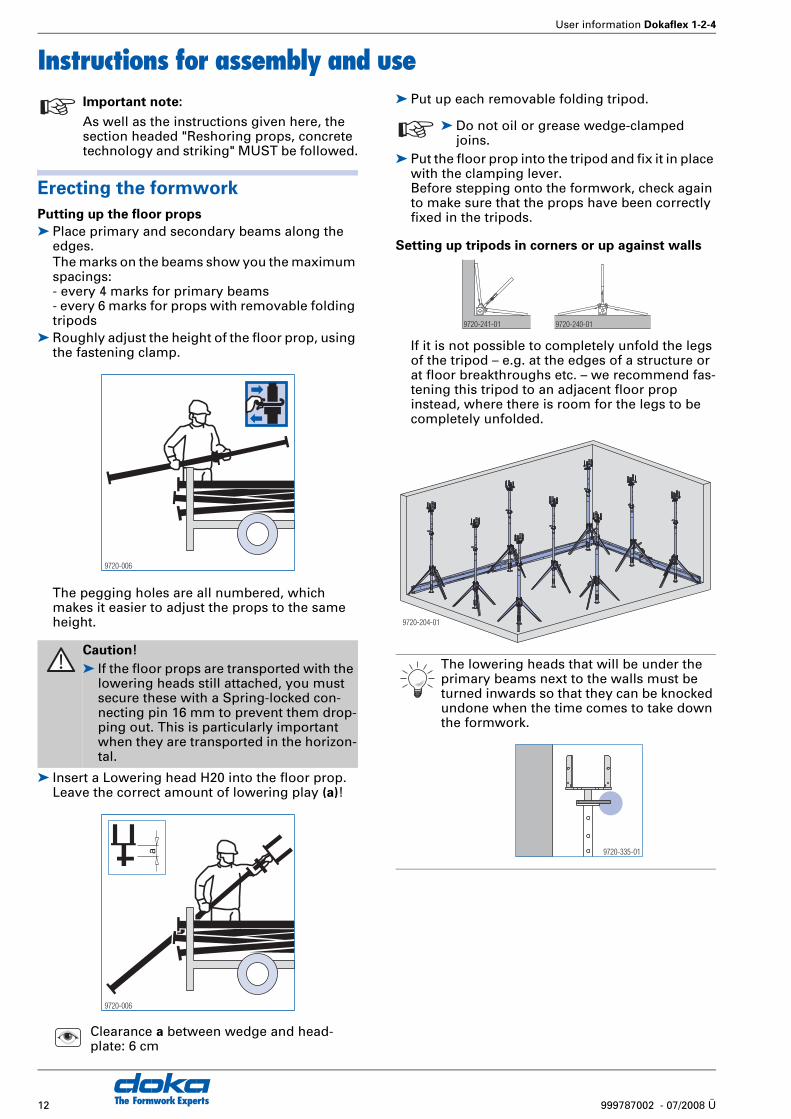
Instructions for assembly and use
Erecting the formwork
Putting up the floor props
➤ Place primary and secondary beams along the edges.The marks on the beams show you the maximum spacings:- every 4 marks for primary beams- every 6 marks for props with removable folding tripods
➤ Roughly adjust the height of the floor prop, using the fastening clamp.
The pegging holes are all numbered, which makes it easier to adjust the props to the same height.
➤ Insert a Lowering head H20 into the floor prop. Leave the correct amount of lowering play (a)!
➤ Put up each removable folding tripod.
➤ Put the floor prop into the tripod and fix it in place with the clamping lever.Before stepping onto the formwork, check again to make sure that the props have been correctly fixed in the tripods.
Setting up tripods in corners or up against walls
If it is not possible to completely unfold the legs of the tripod – e.g. at the edges of a structure or at floor breakthroughs etc. – we recommend fas-tening this tripod to an adjacent floor prop instead, where there is room for the legs to be completely unfolded.
☞ Important note:
As well as the instructions given here, the section headed "Reshoring props, concrete technology and striking" MUST be followed.
Caution!
➤ If the floor props are transported with the lowering heads still attached, you must secure these with a Spring-locked con-necting pin 16 mm to prevent them drop-ping out. This is particularly important when they are transported in the horizon-tal.
Clearance a between wedge and head-plate: 6 cm
9720-006
a
9720-006
☞ ➤ Do not oil or grease wedge-clamped joins.
The lowering heads that will be under the primary beams next to the walls must be turned inwards so that they can be knocked undone when the time comes to take down the formwork.
9720-240-019720-241-01
9720-204-01
9720-335-01
User information Dokaflex 1-2-4
13999787002 - 07/2008 Ü The Formwork Experts
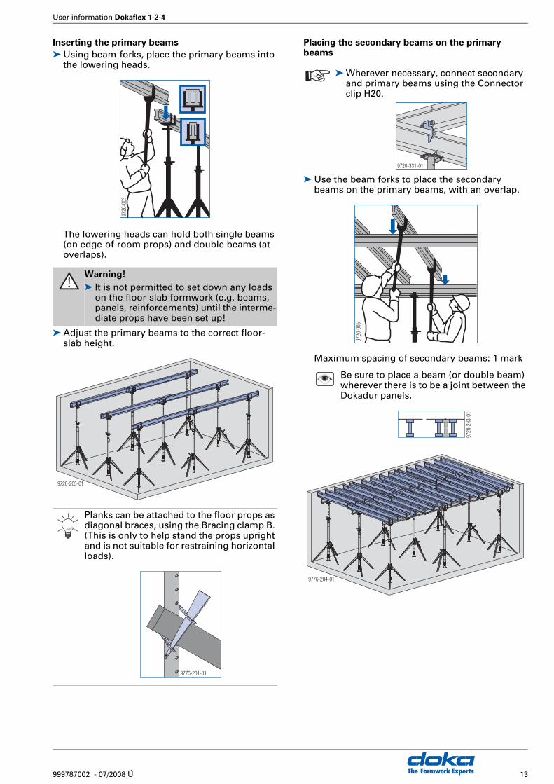
Inserting the primary beams
➤ Using beam-forks, place the primary beams into the lowering heads.
The lowering heads can hold both single beams (on edge-of-room props) and double beams (at overlaps).
➤ Adjust the primary beams to the correct floor-slab height.
Placing the secondary beams on the primary beams
➤ Use the beam forks to place the secondary beams on the primary beams, with an overlap.
Maximum spacing of secondary beams: 1 mark
Warning!
➤ It is not permitted to set down any loads on the floor-slab formwork (e.g. beams, panels, reinforcements) until the interme-diate props have been set up!
Planks can be attached to the floor props as diagonal braces, using the Bracing clamp B. (This is only to help stand the props upright and is not suitable for restraining horizontal loads).
9720
-003
9720-205-01
9776-201-01
☞ ➤ Wherever necessary, connect secondary and primary beams using the Connector clip H20.
Be sure to place a beam (or double beam) wherever there is to be a joint between the Dokadur panels.
9720-331-01
9720
-005
9720
-243
-01
9776-204-01
The Formwork Experts14 999787002 - 07/2008 Ü
User information Dokaflex 1-2-4
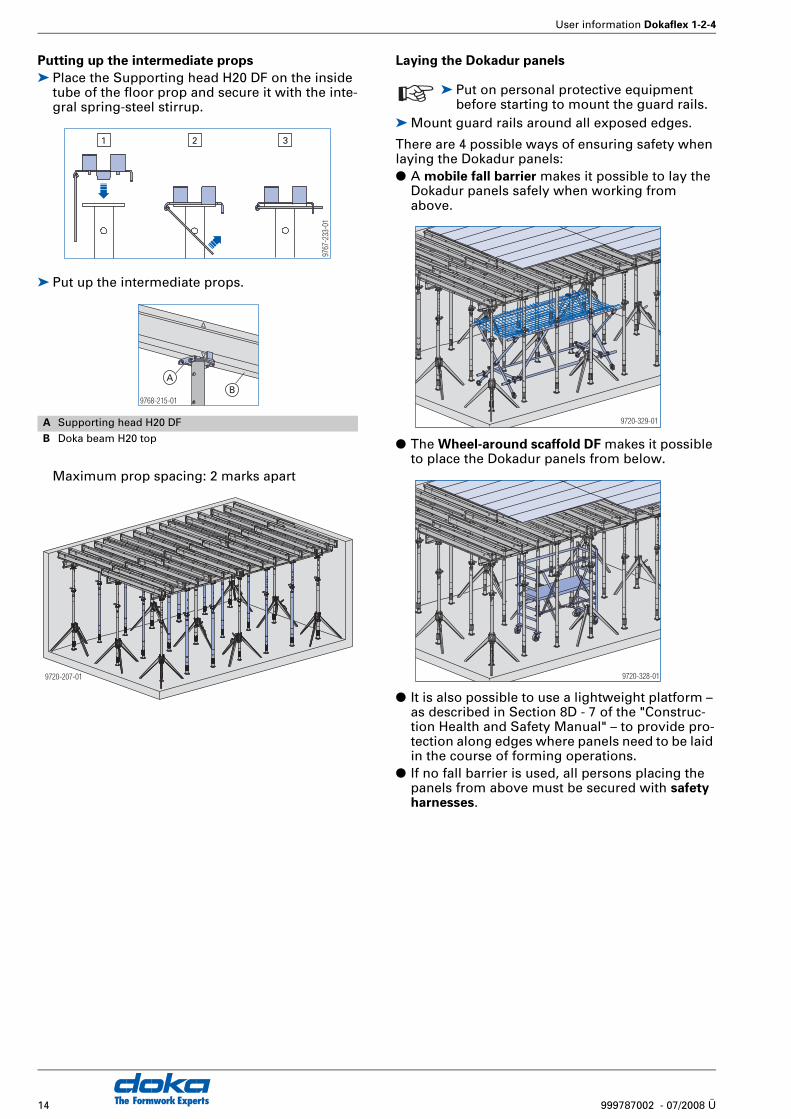
Putting up the intermediate props
➤ Place the Supporting head H20 DF on the inside tube of the floor prop and secure it with the inte-gral spring-steel stirrup.
➤ Put up the intermediate props.
Maximum prop spacing: 2 marks apart
Laying the Dokadur panels
➤ Mount guard rails around all exposed edges.
There are 4 possible ways of ensuring safety when laying the Dokadur panels:● A mobile fall barrier makes it possible to lay the
Dokadur panels safely when working from above.
● The Wheel-around scaffold DF makes it possible to place the Dokadur panels from below.
● It is also possible to use a lightweight platform – as described in Section 8D - 7 of the "Construc-tion Health and Safety Manual" – to provide pro-tection along edges where panels need to be laid in the course of forming operations.
● If no fall barrier is used, all persons placing the panels from above must be secured with safety harnesses.
A Supporting head H20 DF
B Doka beam H20 top
9767
-233
-01
321
9768-215-01
AB
9720-207-01
☞ ➤ Put on personal protective equipment before starting to mount the guard rails.
9720-329-01
9720-328-01
User information Dokaflex 1-2-4
15999787002 - 07/2008 Ü The Formwork Experts
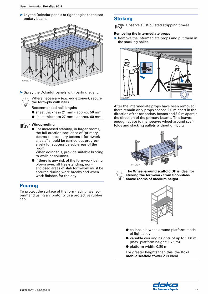
➤ Lay the Dokadur panels at right angles to the sec-ondary beams.
➤ Spray the Dokadur panels with parting agent.
PouringTo protect the surface of the form-facing, we rec-ommend using a vibrator with a protective rubber cap.
Striking
Removing the intermediate props
➤ Remove the intermediate props and put them in the stacking pallet.
After the intermediate props have been removed, there remain only props spaced 2.0 m apart in the direction of the secondary beams and 3.0 m apart in the direction of the primary beams. This leaves enough space to manoeuvre wheel-around scaf-folds and stacking pallets without difficulty.
Where necessary (e.g. edge zones), secure the form-ply with nails.
Recommended nail lengths● sheet thickness 21 mm - approx. 50 mm● sheet thickness 27 mm - approx. 60 mm
☞ Windproofing
● For increased stability, in larger rooms, the full erection sequence of "primary beams + secondary beams + formwork sheets" should be carried out progres-sively for successive sub-areas of the room.When doing this, provide suitable bracing to walls or columns.
● If there is any risk of the formwork being blown over, all free-standing, non-enclosed areas of slab formwork must be secured during work-breaks and when work finishes for the day.
9720-330-01
☞ Observe all stipulated stripping times!
The Wheel-around scaffold DF is ideal for striking the formwork from floor-slabs above rooms of medium height.
● collapsible wheelaround platform made of light alloy
● variable working heights of up to 3.80 m (max. platform height: 1.75 m)
● platform width: 0.80 m
For greater heights than this, the Doka mobile scaffold tower Z is ideal.
9720-006
9768-219-01

The Formwork Experts16 999787002 - 07/2008 Ü
User information Dokaflex 1-2-4
Lowering the floor-slab formwork
➤ Lower the floor-slab formwork by striking the wedge on the lowering head with a hammer.
Removing parts that are no longer needed
➤ Turn the secondary beams over onto their sides, pull them out and put them in the stacking pallet. Leave the beams under the panel-joints in place.
➤ Take out the Dokadur panels and put them in the stacking pallet.
➤ Remove the remaining secondary beams and the primary beams, and put them in the stacking pal-let.
Removing the floor props
1) Hold the inner tube with one hand.2) Open the fastening clamp to unfix the inner tube.
Guide this by hand while lowering it into the outer tube.
➤ Put the removable folding tripods and props in the stacking pallet.
Repropping➤ Before pouring the next floor-slab (i.e. above the
one that has just been stripped), put up reshoring props.
9720-007
9720
-008
9720-009
When lifting the equipment to the next sto-rey, it is better to transport the floor props and the lowering heads separately (the floor props on their own can be stored much more space-savingly in the stacking pallet).
☞ For further information (number of props etc.), see "Reshoring props, concrete tech-nology and striking"
9720-006
1
2

User information Dokaflex 1-2-4
17999787002 - 07/2008 Ü The Formwork Experts
Notes
The Formwork Experts18 999787002 - 07/2008 Ü
User information Dokaflex 1-2-4
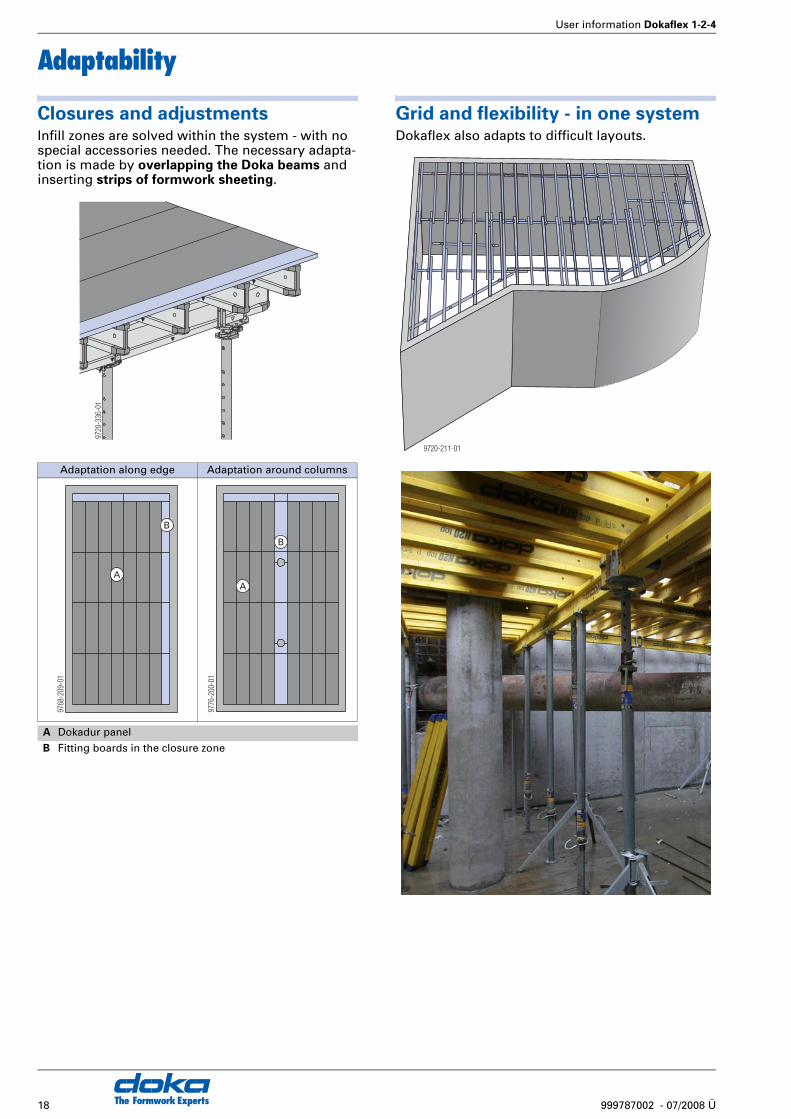
Adaptability
Closures and adjustmentsInfill zones are solved within the system - with no special accessories needed. The necessary adapta-tion is made by overlapping the Doka beams and inserting strips of formwork sheeting.
Grid and flexibility - in one systemDokaflex also adapts to difficult layouts.
Adaptation along edge Adaptation around columns
A Dokadur panel
B Fitting boards in the closure zone
9720
-336
-01
9768
-209
-01
A
B
9776
-200
-01
A
B
9720-211-01
User information Dokaflex 1-2-4
19999787002 - 07/2008 Ü The Formwork Experts
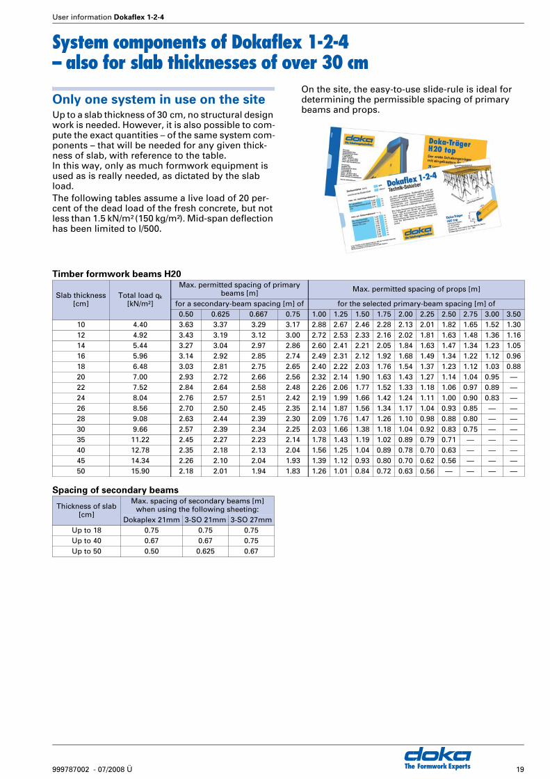
System components of Dokaflex 1-2-4– also for slab thicknesses of over 30 cm
Only one system in use on the siteUp to a slab thickness of 30 cm, no structural design work is needed. However, it is also possible to com-pute the exact quantities – of the same system com-ponents – that will be needed for any given thick-ness of slab, with reference to the table.In this way, only as much formwork equipment is used as is really needed, as dictated by the slab load.The following tables assume a live load of 20 per-cent of the dead load of the fresh concrete, but not less than 1.5 kN/m² (150 kg/m²). Mid-span deflection has been limited to l/500.
On the site, the easy-to-use slide-rule is ideal for determining the permissible spacing of primary beams and props.
Timber formwork beams H20
Spacing of secondary beams
Slab thickness[cm]
Total load qk
[kN/m2]
Max. permitted spacing of primary beams [m] Max. permitted spacing of props [m]
for a secondary-beam spacing [m] of for the selected primary-beam spacing [m] of0.50 0.625 0.667 0.75 1.00 1.25 1.50 1.75 2.00 2.25 2.50 2.75 3.00 3.50
10 4.40 3.63 3.37 3.29 3.17 2.88 2.67 2.46 2.28 2.13 2.01 1.82 1.65 1.52 1.3012 4.92 3.43 3.19 3.12 3.00 2.72 2.53 2.33 2.16 2.02 1.81 1.63 1.48 1.36 1.1614 5.44 3.27 3.04 2.97 2.86 2.60 2.41 2.21 2.05 1.84 1.63 1.47 1.34 1.23 1.0516 5.96 3.14 2.92 2.85 2.74 2.49 2.31 2.12 1.92 1.68 1.49 1.34 1.22 1.12 0.9618 6.48 3.03 2.81 2.75 2.65 2.40 2.22 2.03 1.76 1.54 1.37 1.23 1.12 1.03 0.8820 7.00 2.93 2.72 2.66 2.56 2.32 2.14 1.90 1.63 1.43 1.27 1.14 1.04 0.95 —22 7.52 2.84 2.64 2.58 2.48 2.26 2.06 1.77 1.52 1.33 1.18 1.06 0.97 0.89 —24 8.04 2.76 2.57 2.51 2.42 2.19 1.99 1.66 1.42 1.24 1.11 1.00 0.90 0.83 —26 8.56 2.70 2.50 2.45 2.35 2.14 1.87 1.56 1.34 1.17 1.04 0.93 0.85 — —28 9.08 2.63 2.44 2.39 2.30 2.09 1.76 1.47 1.26 1.10 0.98 0.88 0.80 — —30 9.66 2.57 2.39 2.34 2.25 2.03 1.66 1.38 1.18 1.04 0.92 0.83 0.75 — —35 11.22 2.45 2.27 2.23 2.14 1.78 1.43 1.19 1.02 0.89 0.79 0.71 — — —40 12.78 2.35 2.18 2.13 2.04 1.56 1.25 1.04 0.89 0.78 0.70 0.63 — — —45 14.34 2.26 2.10 2.04 1.93 1.39 1.12 0.93 0.80 0.70 0.62 0.56 — — —50 15.90 2.18 2.01 1.94 1.83 1.26 1.01 0.84 0.72 0.63 0.56 — — — —
Thickness of slab [cm]
Max. spacing of secondary beams [m] when using the following sheeting:
Dokaplex 21mm 3-SO 21mm 3-SO 27mmUp to 18 0.75 0.75 0.75Up to 40 0.67 0.67 0.75Up to 50 0.50 0.625 0.67
The Formwork Experts20 999787002 - 07/2008 Ü
User information Dokaflex 1-2-4
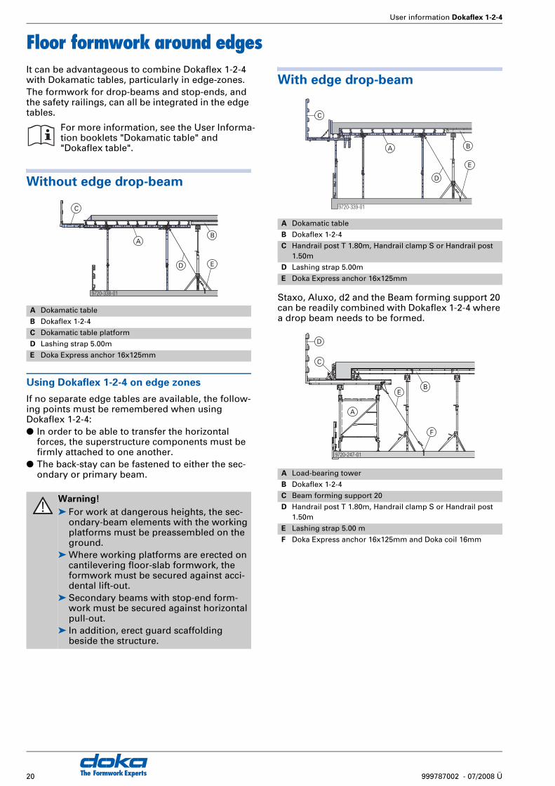
Floor formwork around edgesIt can be advantageous to combine Dokaflex 1-2-4 with Dokamatic tables, particularly in edge-zones.The formwork for drop-beams and stop-ends, and the safety railings, can all be integrated in the edge tables.
Without edge drop-beam
Using Dokaflex 1-2-4 on edge zones
If no separate edge tables are available, the follow-ing points must be remembered when using Dokaflex 1-2-4:● In order to be able to transfer the horizontal
forces, the superstructure components must be firmly attached to one another.
● The back-stay can be fastened to either the sec-ondary or primary beam.
With edge drop-beam
Staxo, Aluxo, d2 and the Beam forming support 20 can be readily combined with Dokaflex 1-2-4 where a drop beam needs to be formed.
For more information, see the User Informa-tion booklets "Dokamatic table" and "Dokaflex table".
A Dokamatic table
B Dokaflex 1-2-4
C Dokamatic table platform
D Lashing strap 5.00m
E Doka Express anchor 16x125mm
Warning!
➤ For work at dangerous heights, the sec-ondary-beam elements with the working platforms must be preassembled on the ground.
➤ Where working platforms are erected on cantilevering floor-slab formwork, the formwork must be secured against acci-dental lift-out.
➤ Secondary beams with stop-end form-work must be secured against horizontal pull-out.
➤ In addition, erect guard scaffolding beside the structure.
9720-338-01
A
C
D
B
E
A Dokamatic table
B Dokaflex 1-2-4
C Handrail post T 1.80m, Handrail clamp S or Handrail post 1.50m
D Lashing strap 5.00m
E Doka Express anchor 16x125mm
A Load-bearing tower
B Dokaflex 1-2-4
C Beam forming support 20
D Handrail post T 1.80m, Handrail clamp S or Handrail post 1.50m
E Lashing strap 5.00 m
F Doka Express anchor 16x125mm and Doka coil 16mm
9720-339-01
A
C
D
B
E
9720-247-01
A
D
C
B
F
E
User information Dokaflex 1-2-4
21999787002 - 07/2008 Ü The Formwork Experts
Safety on the structure
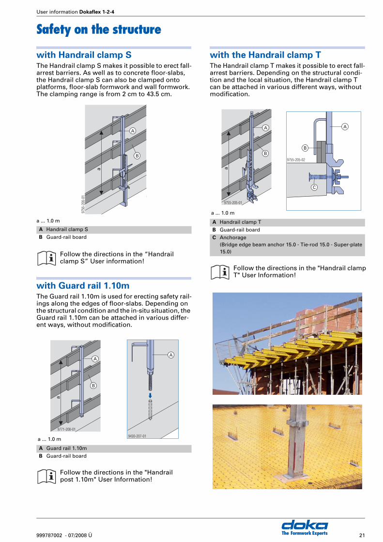
with Handrail clamp SThe Handrail clamp S makes it possible to erect fall-arrest barriers. As well as to concrete floor-slabs, the Handrail clamp S can also be clamped onto platforms, floor-slab formwork and wall formwork. The clamping range is from 2 cm to 43.5 cm.
a ... 1.0 m
with Guard rail 1.10mThe Guard rail 1.10m is used for erecting safety rail-ings along the edges of floor-slabs. Depending on the structural condition and the in-situ situation, the Guard rail 1.10m can be attached in various differ-ent ways, without modification.
with the Handrail clamp TThe Handrail clamp T makes it possible to erect fall-arrest barriers. Depending on the structural condi-tion and the local situation, the Handrail clamp T can be attached in various different ways, without modification.
A Handrail clamp S
B Guard-rail board
Follow the directions in the “Handrail clamp S” User information!
a ... 1.0 m
A Guard rail 1.10m
B Guard-rail board
Follow the directions in the "Handrail post 1.10m" User Information!
9756
-206
-01
a
A
B
9771-200-01
a
A
B
9430-207-01
A
a ... 1.0 m
A Handrail clamp T
B Guard-rail board
C Anchorage (Bridge edge beam anchor 15.0 - Tie-rod 15.0 - Super-plate 15.0)
Follow the directions in the "Handrail clamp T" User Information!
9755-205-01
a
A
B9755-205-02
A
B
C

The Formwork Experts22 999787002 - 07/2008 Ü
User information Dokaflex 1-2-4
Beam forming supportThe Beam forming support 20 is the professional way of forming drop beams and slab stop-ends. In conjunction with the "Extension 60 cm for beam support", exact height adjustment to within 1 cm is possible.This does away with time-consuming jobsite squared-timber constructions. The Beam forming support automatically clamps the formwork tight, resulting in clean concrete surfaces and grout-tight edges.
How to use the Beam forming sup-
port 20➤ Place the Beam-forming support onto the H 20
secondary beam and push it up against the side-wall formwork.
The large bearing surface of the Beam-forming support gives the sidewall formwork a high degree of (90°) angle accuracy.
➤ Clamp the Beam forming support firmly into position
The diagonal bracing of the Beam-forming sup-port ensures that the joint between the form-ply sheets is automatically pressed together tightly when the Beam forming support is clamped.
This results in a clean concrete surface.
Formwork beams horizontal
(up to a height of 60 cm)
Note:
As a basic rule, it is forbidden to use formwork beams "horizontally" (i.e. with the load-direction perpendicular to the web). However, the specific applications shown here, using the Beam forming support, are permitted.
Formwork beams vertical
(up to a height of 90 cm)
A Beam forming support 20
B Extension 60 cm for beam support
5861
4900
0-3b
B
586148000-3b
A
9720-321-01
9720-322-01
9720-323-01
9720-324-01
9720-232-01
9720-233-01

User information Dokaflex 1-2-4
23999787002 - 07/2008 Ü The Formwork Experts
Drop-beam not integrated into the floor-slab / stop-end formworkAll the data below apply where 3-SO 21 mm and 3-SO 27 mm formwork sheets are used.
Drop beams of between 10 and
30 cm in height
b ... max. 100 cml ... max. 150 cm
Sidewall formwork:● Doka beam H20 top
Drop beams of between 30 and 47 cm in height
b ... max. 100 cml ... max. 150 cm
Sidewall formwork:● Doka beam H20 top● Squared timber 4/8 cm for drop beams of
between 30 and 34 cm in height● Squared timber 8/8 cm for drop beams of
between 34 and 47 cm in height
Drop beams of between 47 and
70 cm in height
b ... max. 100 cml ... max. 150 cm
Sidewall formwork:● 2 Doka beams H20 top
Drop beams of between 70 and 90 cm in height
b ... max. 100 cml ... max. 150 cm
Sidewall formwork:● Doka formwork beams H20 in the upright
h... Drop-beam heightb... Drop-beam widthl... Spacing of primary beams
Spacing of secondary beams
Position of Beam forming support
50.0 cm On every 3rd secondary beam
Spacing of secondary beams
Position of Beam forming support
50.0 cm On every 2nd secondary beam
9720-249-01
h
b
l
9720-250-01
h
b
l
h Spacing of secondary beams
Position of Beam forming support
Up to 60 cmFrom 60 cm
50.0 cm33.3 cm
On every 2nd secondary beamOn every 2nd secondary beam
Where the dimensional requirements are especially stringent, we recommend placing a form-tie (A) through the sidewall form-work as an additional precaution.
h Spacing of secondary beams
Position of Beam forming support
Up to 85 cmFrom 85 cm
41.7 cm36.0 cm
On every secondary beamOn every secondary beam
9720-251-01
h
b
l
9720-252-01
h
b
l
A
The Formwork Experts24 999787002 - 07/2008 Ü
User information Dokaflex 1-2-4
Drop-beam integrated into the floor-slab
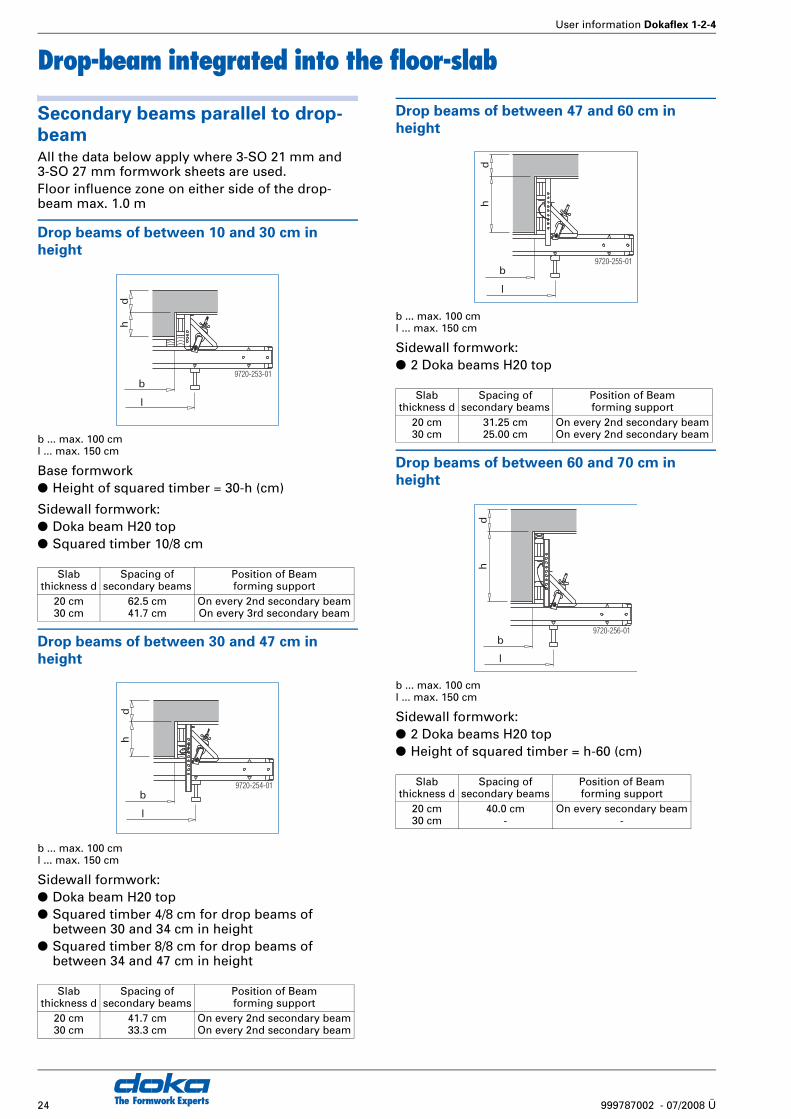
Secondary beams parallel to drop-
beamAll the data below apply where 3-SO 21 mm and 3-SO 27 mm formwork sheets are used.Floor influence zone on either side of the drop-beam max. 1.0 m
Drop beams of between 10 and 30 cm in
height
b ... max. 100 cml ... max. 150 cm
Base formwork● Height of squared timber = 30-h (cm)
Sidewall formwork:● Doka beam H20 top● Squared timber 10/8 cm
Drop beams of between 30 and 47 cm in
height
b ... max. 100 cml ... max. 150 cm
Sidewall formwork:● Doka beam H20 top● Squared timber 4/8 cm for drop beams of
between 30 and 34 cm in height● Squared timber 8/8 cm for drop beams of
between 34 and 47 cm in height
Drop beams of between 47 and 60 cm in
height
b ... max. 100 cml ... max. 150 cm
Sidewall formwork:● 2 Doka beams H20 top
Drop beams of between 60 and 70 cm in
height
b ... max. 100 cml ... max. 150 cm
Sidewall formwork:● 2 Doka beams H20 top● Height of squared timber = h-60 (cm)
Slab thickness d
Spacing of secondary beams
Position of Beam forming support
20 cm30 cm
62.5 cm41.7 cm
On every 2nd secondary beamOn every 3rd secondary beam
Slab thickness d
Spacing of secondary beams
Position of Beam forming support
20 cm30 cm
41.7 cm33.3 cm
On every 2nd secondary beamOn every 2nd secondary beam
9720-253-01
hd
b
l
9720-254-01
hd
b
l
Slab thickness d
Spacing of secondary beams
Position of Beam forming support
20 cm30 cm
31.25 cm25.00 cm
On every 2nd secondary beamOn every 2nd secondary beam
Slab thickness d
Spacing of secondary beams
Position of Beam forming support
20 cm30 cm
40.0 cm-
On every secondary beam-
9720-255-01
hd
b
l
9720-256-01
hd
b
l
User information Dokaflex 1-2-4
25999787002 - 07/2008 Ü The Formwork Experts
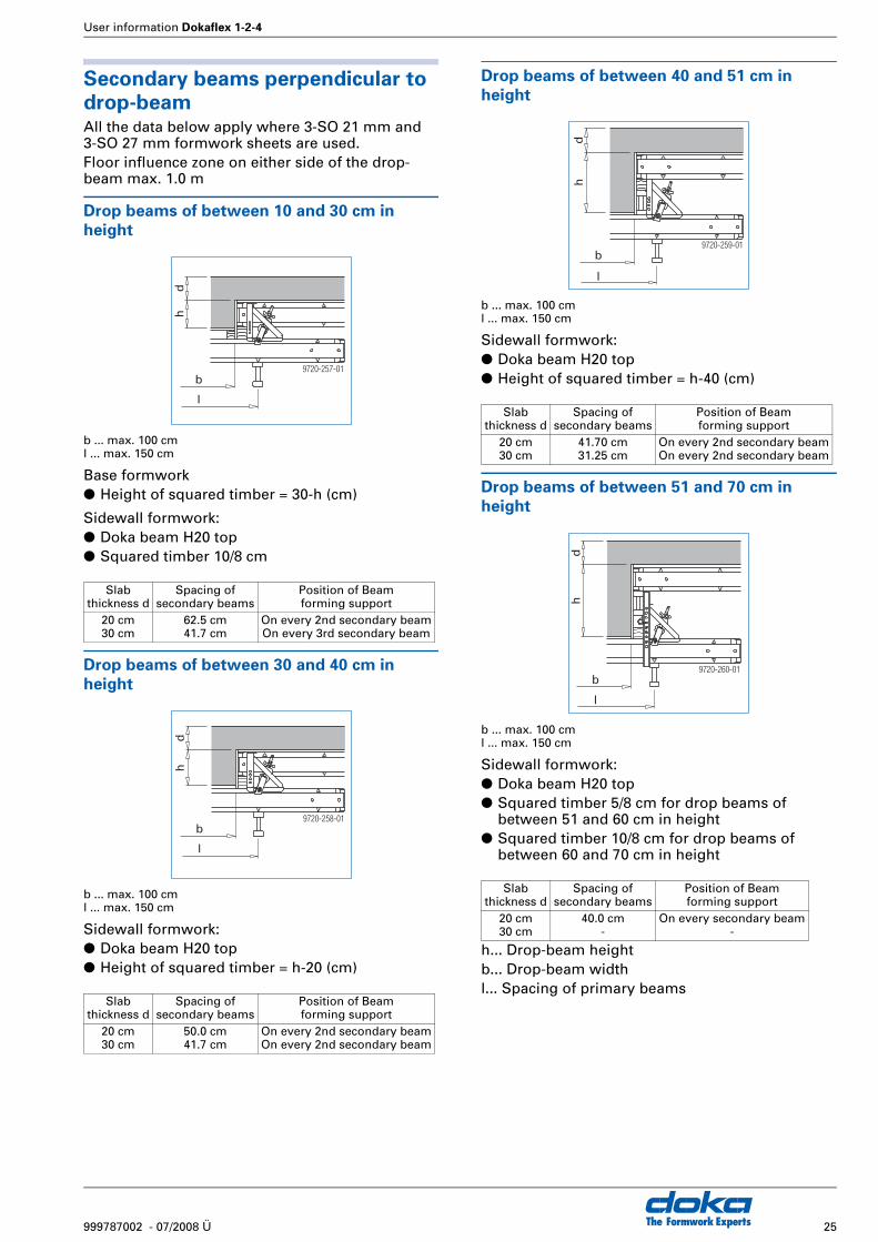
Secondary beams perpendicular to
drop-beamAll the data below apply where 3-SO 21 mm and 3-SO 27 mm formwork sheets are used.Floor influence zone on either side of the drop-beam max. 1.0 m
Drop beams of between 10 and 30 cm in
height
b ... max. 100 cml ... max. 150 cm
Base formwork● Height of squared timber = 30-h (cm)
Sidewall formwork:● Doka beam H20 top● Squared timber 10/8 cm
Drop beams of between 30 and 40 cm in
height
b ... max. 100 cml ... max. 150 cm
Sidewall formwork:● Doka beam H20 top● Height of squared timber = h-20 (cm)
Drop beams of between 40 and 51 cm in
height
b ... max. 100 cml ... max. 150 cm
Sidewall formwork:● Doka beam H20 top● Height of squared timber = h-40 (cm)
Drop beams of between 51 and 70 cm in
height
b ... max. 100 cml ... max. 150 cm
Sidewall formwork:● Doka beam H20 top● Squared timber 5/8 cm for drop beams of
between 51 and 60 cm in height● Squared timber 10/8 cm for drop beams of
between 60 and 70 cm in height
h... Drop-beam heightb... Drop-beam widthl... Spacing of primary beams
Slab thickness d
Spacing of secondary beams
Position of Beam forming support
20 cm30 cm
62.5 cm41.7 cm
On every 2nd secondary beamOn every 3rd secondary beam
Slab thickness d
Spacing of secondary beams
Position of Beam forming support
20 cm30 cm
50.0 cm41.7 cm
On every 2nd secondary beamOn every 2nd secondary beam
9720-257-01
hd
b
l
9720-258-01
hd
b
l
Slab thickness d
Spacing of secondary beams
Position of Beam forming support
20 cm30 cm
41.70 cm31.25 cm
On every 2nd secondary beamOn every 2nd secondary beam
Slab thickness d
Spacing of secondary beams
Position of Beam forming support
20 cm30 cm
40.0 cm-
On every secondary beam-
9720-259-01
hd
b
l
9720-260-01
hd
b
l
The Formwork Experts26 999787002 - 07/2008 Ü
User information Dokaflex 1-2-4
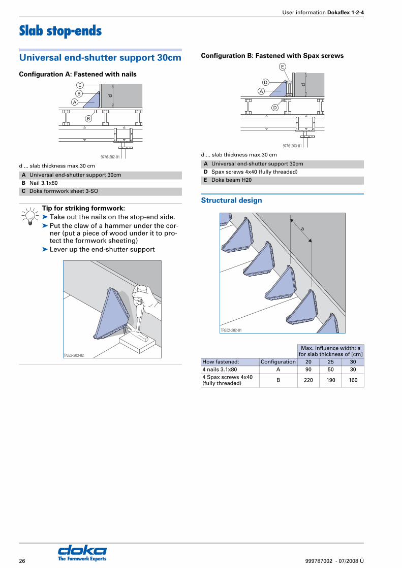
Slab stop-ends
Universal end-shutter support 30cm
Configuration A: Fastened with nails
d ... slab thickness max.30 cm
Configuration B: Fastened with Spax screws
d ... slab thickness max.30 cm
Structural design
A Universal end-shutter support 30cm
B Nail 3.1x80
C Doka formwork sheet 3-SO
Tip for striking formwork:
➤ Take out the nails on the stop-end side.➤ Put the claw of a hammer under the cor-
ner (put a piece of wood under it to pro-tect the formwork sheeting)
➤ Lever up the end-shutter support
9776-202-01
d
B
A
B
C
Tr652-203-02
A Universal end-shutter support 30cm
D Spax screws 4x40 (fully threaded)
E Doka beam H20
Max. influence width: afor slab thickness of [cm]
How fastened: Configuration 20 25 304 nails 3.1x80 A 90 50 304 Spax screws 4x40(fully threaded) B 220 190 160
d
D
A
D
E
9776-203-01
TR652-202-01
a
User information Dokaflex 1-2-4
27999787002 - 07/2008 Ü The Formwork Experts
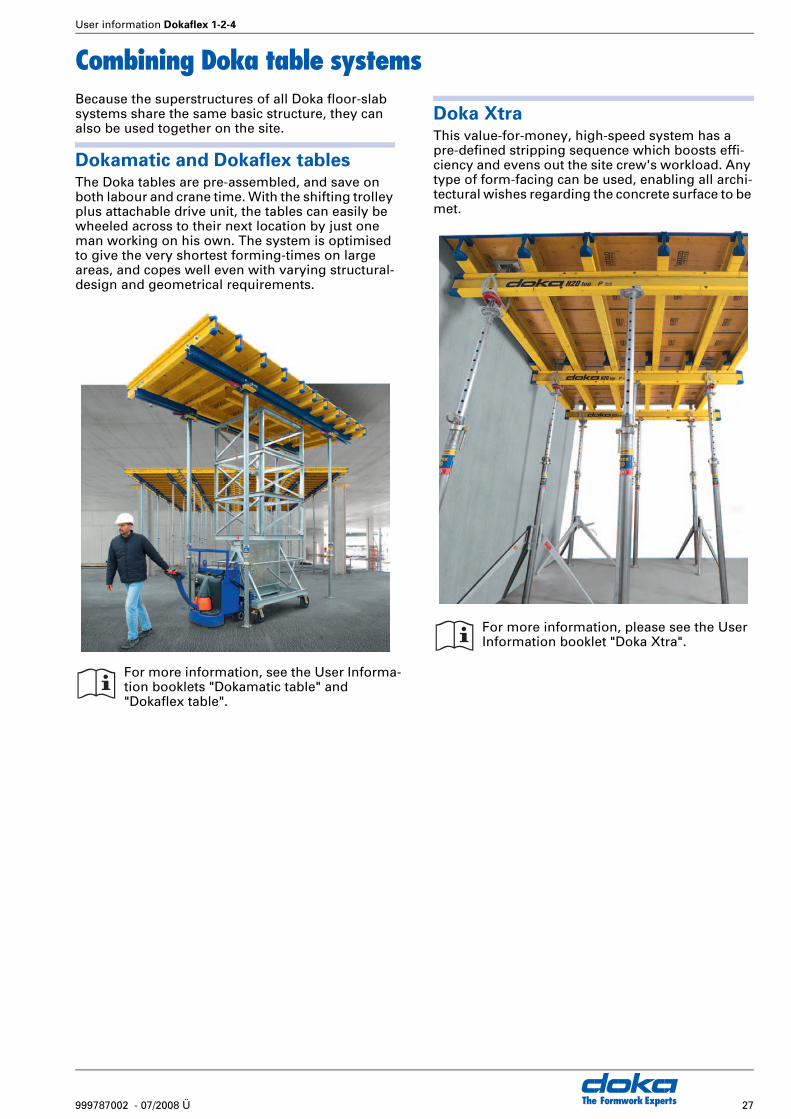
Combining Doka table systemsBecause the superstructures of all Doka floor-slab systems share the same basic structure, they can also be used together on the site.
Dokamatic and Dokaflex tablesThe Doka tables are pre-assembled, and save on both labour and crane time. With the shifting trolley plus attachable drive unit, the tables can easily be wheeled across to their next location by just one man working on his own. The system is optimised to give the very shortest forming-times on large areas, and copes well even with varying structural-design and geometrical requirements.
Doka XtraThis value-for-money, high-speed system has a pre-defined stripping sequence which boosts effi-ciency and evens out the site crew's workload. Any type of form-facing can be used, enabling all archi-tectural wishes regarding the concrete surface to be met.
For more information, see the User Informa-tion booklets "Dokamatic table" and "Dokaflex table".
For more information, please see the User Information booklet "Doka Xtra".

The Formwork Experts28 999787002 - 07/2008 Ü
User information Dokaflex 1-2-4
Transporting, stacking and storing
Doka skeleton transport box
1.70x0.80m
The ideal container for all small components:● durable● stackable● safe to lift by crane
The Doka skeleton transport box is used for deliver-ing e.g.:● Removable folding tripods● Handrail clamps S
Doka multi-trip transport box
1.20x0.80m galv.
The ideal container for all small components:● durable● stackable● safe to lift by crane
The Doka multi-trip transport box is used for deliv-ering e.g.:● Doka lowering heads● Supporting heads H20 DF
Multi-trip transport box partition
Different items in the Multi-trip transport box can be kept separate with the Multi-trip transport box partitions 1.20m or 0.80m.
Possible ways of dividing the box
Utilise the benefits of Doka multi-trip packaging on your site.
When it comes to streamlining the transport and handling of formwork equipment, Doka offers tried-and-tested help – by delivering it in multi-trip packaging. Any packaging items that are no longer needed can simply be returned to your nearest Doka branch.
Max. load: 700 kg
Follow the directions in the Operating Instructions!
Max. load: 1500 kg
Follow the directions in the Operating Instructions!
A Slide-bolt for fixing the partition
Multi-trip transport box partition Lengthways Crossways
1.20m max. 3 partitions —0.80m — max. 3 partitions
Tr75
5-20
0-02
A
Tr755-200-04 Tr755-200-05
User information Dokaflex 1-2-4
29999787002 - 07/2008 Ü The Formwork Experts
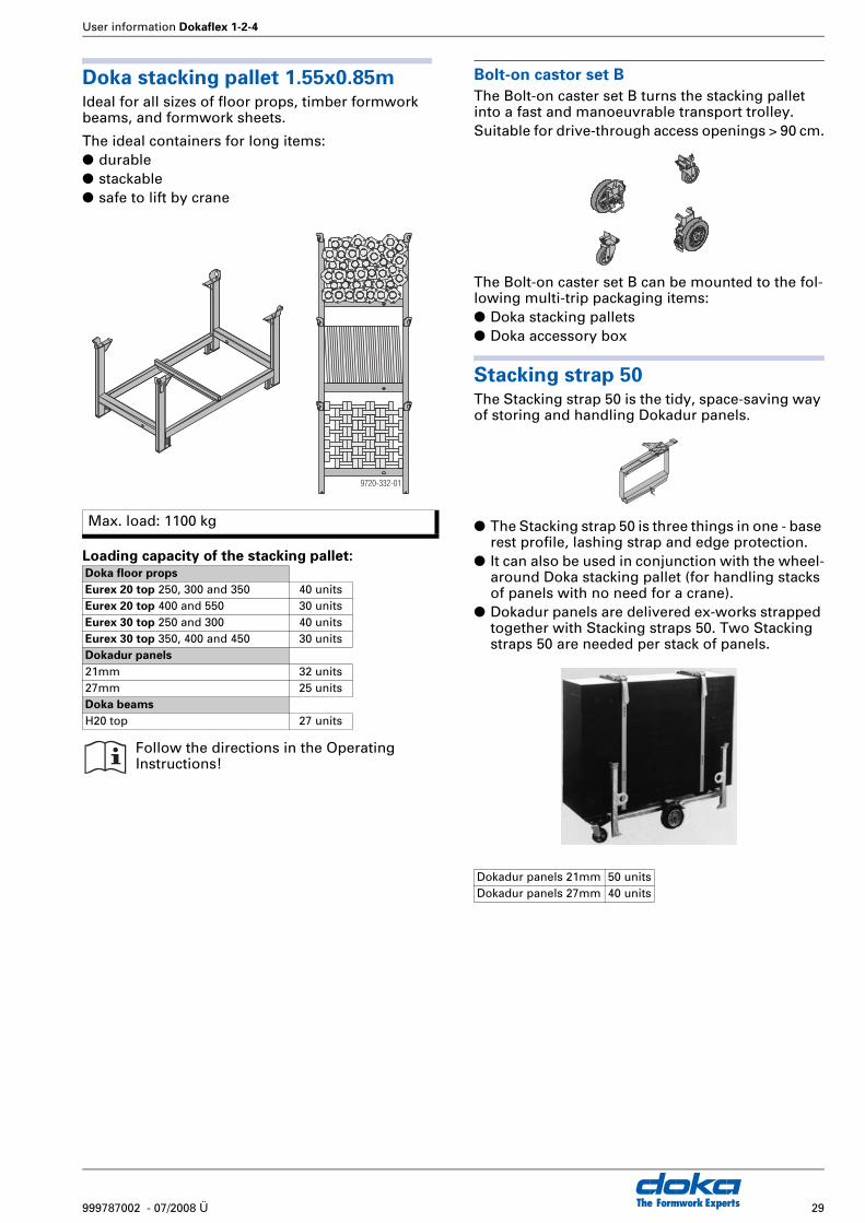
Doka stacking pallet 1.55x0.85mIdeal for all sizes of floor props, timber formwork beams, and formwork sheets.
The ideal containers for long items:● durable● stackable● safe to lift by crane
Loading capacity of the stacking pallet:
Bolt-on castor set B
The Bolt-on caster set B turns the stacking pallet into a fast and manoeuvrable transport trolley.Suitable for drive-through access openings > 90 cm.
The Bolt-on caster set B can be mounted to the fol-lowing multi-trip packaging items:● Doka stacking pallets● Doka accessory box
Stacking strap 50The Stacking strap 50 is the tidy, space-saving way of storing and handling Dokadur panels.
● The Stacking strap 50 is three things in one - base rest profile, lashing strap and edge protection.
● It can also be used in conjunction with the wheel-around Doka stacking pallet (for handling stacks of panels with no need for a crane).
● Dokadur panels are delivered ex-works strapped together with Stacking straps 50. Two Stacking straps 50 are needed per stack of panels.
Max. load: 1100 kg
Doka floor props
Eurex 20 top 250, 300 and 350 40 unitsEurex 20 top 400 and 550 30 unitsEurex 30 top 250 and 300 40 unitsEurex 30 top 350, 400 and 450 30 unitsDokadur panels
21mm 32 units27mm 25 unitsDoka beams
H20 top 27 units
Follow the directions in the Operating Instructions!
9720-332-01
Dokadur panels 21mm 50 unitsDokadur panels 27mm 40 units

The Formwork Experts30 999787002 - 07/2008 Ü
User information Dokaflex 1-2-4
Reshoring props, concrete technology and striking
When is the best time to strike?In the building construction field, the load occurring during pouring (i.e. the weight of the uncovered floor) will generally be approx. 50% of the design load of the floor-slab (dead weight + flooring + serv-ice load).This means that the formwork can be struck once the concrete has reached 50% of its 28-day strength. The loading safety of the floor-slab is then equal to that of the finished structure.
Why put up reshoring props after
striking the formwork?Depending on the construction sequence, reshor-ing props may be needed to carry service loads on the new floor-slab, and/or concreting-loads from the next floor to be poured.
Positioning the reshoring props cor-
rectlyReshoring props have the job of spreading loads between the new floor-slab and the floor beneath it. This load distribution will depend on the relation-ship between the rigidities of these two floor-slabs.
The required numerical relationship between reshoring props and formwork props can be stated for the following two limit cases:● only approx. 0.4 reshoring props per formwork
prop where both floor-slabs have similar rigidi-ties
● only approx. 0.8 reshoring props per formwork prop where the floor-slab below has a considera-bly higher rigidity (foundation slab).
Strength development in the new
concreteThis diagram shows the strength development where different grades of cement are used. The pre-condition here is that there is an average tempera-ture of 20°C in the concrete during the curing period.
Water/binding-agent (cement) ratio = 0.50
Deflection of the new concreteThe modulus of elasticity of the concrete has already reached more than 90 % of the 28-day value after only 3 days, regardless of the formulation of the concrete. The increase in the elastic deforma-tion taking place in the new concrete is thus only negligible.The creep deformation, which only finally ceases after several years, is several times more than the elastic deformation.However, early striking - e.g. after 3 days instead of 28 - only leads to an increase in the total deforma-tion of less than 5 %.The part of this deformation accounted for by creep deformation, however, may be anything between 50 % and 100 % of the standard value, due to such variable influences as the strength of the aggre-gates, and the atmospheric humidity. This means that the total deflection of the floor-slab is practi-cally independent of the time at which the form-work was struck.
☞ Important note:
If the load is not removed from the floor props at this stage, they will remain loaded with the dead weight of the floor-slab.When the floor above is concreted, this may lead to a doubling of the load that is being applied to the floor props.
The floor props are not designed to cope with such an overload, and the result may be damage to the formwork, the floor props and the structure.
☞ Ask an expert!
As a rule, the question of using reshoring props should be referred to the responsible experts, regardless of the information given above. If there is any doubt, particularly where dissimilar floor systems are involved, the decision must be referred to the respon-sible structural designer.
Co
mp
ress
ive
stre
ng
th a
s a
%ag
e o
f th
e 28
-day
val
ue
β WN
,t /
β WN
,28
Age of concrete in days
A Z 45 F, PZ 475
B Z 35 F, PZ 375
C Z 35 L (blast-furnace cement with 60% blast-furnace slag)
9720-100
100
0 1 3 7 28
20
40
60
80
B
C
A
User information Dokaflex 1-2-4
31999787002 - 07/2008 Ü The Formwork Experts
Cracks in new concreteThe bonding strength between the reinforcement steel and the concrete develops more rapidly in the new concrete than does its compressive strength. This means that early striking does not have any negative influence upon the size and distribution of cracks on the tension side of reinforced concrete constructions.Other cracking phenomena caused by e.g. shrink-age, premature striking, impeded deformation etc. can be countered effectively by appropriate curing methods.
Curing of new concrete
New site-placed concrete is exposed to influences which may cause cracking and slow down its strength development:● premature drying● over-rapid cooling in the first few days● excessively low temperatures or frost● mechanical damage to the surface of the con-
crete● etc.The simplest precaution is to leave the formwork on the concrete surface for longer. As well as the famil-iar extra curing measures, this measure should be carried out in any case.
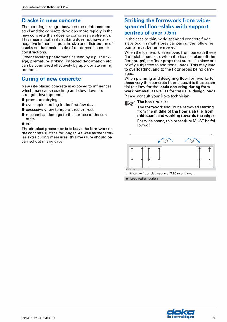
Striking the formwork from wide-
spanned floor-slabs with support centres of over 7.5mIn the case of thin, wide-spanned concrete floor-slabs (e.g. in multistorey car parks), the following points must be remembered:When the formwork is removed from beneath these floor-slab spans (i.e. when the load is taken off the floor props), the floor props that are still in place are briefly subjected to additional loads. This may lead to overloading, and to the floor props being dam-aged.When planning and designing floor formworks for these very thin concrete floor slabs, it is thus essen-tial to allow for the loads occurring during form-work removal, as well as for the usual design loads.Please consult your Doka technician.
l ... Effective floor-slab spans of 7.50 m and over
☞ The basic rule is:
The formwork should be removed starting from the middle of the floor slab (i.e. from mid-span), and working towards the edges. For wide spans, this procedure MUST be fol-lowed!
A Load redistribution
9767-214-01
l
A A

The Formwork Experts32 999787002 - 07/2008 Ü
User information Dokaflex 1-2-4
Formwork planning with Tipos
Tipos-Doka helps you to form even
more efficientlyTipos has been developed to assist you in planning the use of your Doka formwork. For wall formwork, floor formwork and platforms, it puts the same tools into your hands that we at Doka use our-selves for formwork planning.
Easy to use, fast and accurate
resultsThe easy-to-use interface makes for very fast work-ing. From when you input your layout (with the "Schal-Igel"® on-screen assistant), all the way through to when you manually put the finishing touches to the formwork solution the program gives you. All this saves time - yours.The program contains a large number of templates from formwork practice, so you can be sure of always getting the optimum technical and econom-ical solution to your formwork task. This makes for greater operational reliability, and cuts costs.You can get to work right away with the piece-lists, plans, views, sections and perspective drawings that the program gives you. Operational reliability is also enhanced by the high level of detail of the plans.
Formwork drawings really can be as clear and detailed as this! Both for the layout and for spatial representations, Tipos-Doka sets an impressive new standard of visual presentation.
Always the right quantities of form-
work and accessories
You can import the automatically generated piece-lists into many other programs for further processing.
Formwork components and accessories that have to be organised at short notice, or replaced by improvisation, are the ones that cost the most. This is why Tipos-Doka offers complete piece-lists that leave no room for improvisation. Planning with Tipos-Doka eliminates costs before they have a chance to even arise. And your depot can make the best possible use of its stocks.

User information Dokaflex 1-2-4
33999787002 - 07/2008 Ü The Formwork Experts
Doka service offerings
Doka Reconditioning Service
So that your formwork is in "top form" for its
next assignment
Inspecting, cleaning and maintaining your Dokaflex system – the Doka Reconditioning Service will be pleased to take care of all of these tasks for you. Its highly qualified staff and special equipment will soon get your formwork back in top form, quickly and economically.The advantage for you: You always have formwork that is ready for use, and also extend the service life of your equipment.What's more: It is only with well-maintained form-work that you will achieve the desired quality of concrete surface.In our modern plants, your formwork will be care-fully cleaned using energy-saving and environmen-tally sound technology.
Doka customer training
Formwork training pays
Forming operations account for the lion’s share of labour costs on concrete construction sites. Modern formwork equipment helps to rationalise opera-tions. By improving the overall construction sequence at the same time, however, further very worthwhile gains in efficiency can be achieved.This requires not only better equipment, but also greater skill in making optimum use of this equip-ment. Doka can help here, with its specialist train-ing programme - to help each and every member of the team do his bit towards boosting efficiency and lowering costs.Doka customer training events also look at the formwork equipment and handling methods that are needed in order to achieve optimum safety - knowledge and awareness which can only enhance workplace safety on the site.You’ll find the Doka training programme well worth looking into.
Your nearest Doka branch will be pleased to tell you more about Doka's various training offerings.
Article n°[kg] Article n°[kg]
34 999787002 - 07/2008 Ü
User information Dokaflex 1-2-4
The Formwork Experts
Component overview
Doka Floor SystemDokaflex 1-2-4
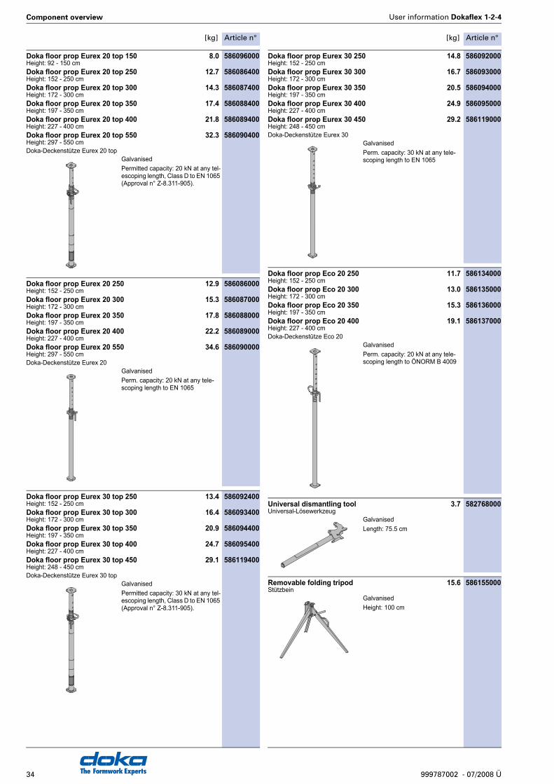
Doka floor prop Eurex 20 top 150 8.0 586096000Height: 92 - 150 cmDoka floor prop Eurex 20 top 250 12.7 586086400Height: 152 - 250 cmDoka floor prop Eurex 20 top 300 14.3 586087400Height: 172 - 300 cmDoka floor prop Eurex 20 top 350 17.4 586088400Height: 197 - 350 cmDoka floor prop Eurex 20 top 400 21.8 586089400Height: 227 - 400 cmDoka floor prop Eurex 20 top 550 32.3 586090400Height: 297 - 550 cmDoka-Deckenstütze Eurex 20 top
Doka floor prop Eurex 20 250 12.9 586086000Height: 152 - 250 cmDoka floor prop Eurex 20 300 15.3 586087000Height: 172 - 300 cmDoka floor prop Eurex 20 350 17.8 586088000Height: 197 - 350 cmDoka floor prop Eurex 20 400 22.2 586089000Height: 227 - 400 cmDoka floor prop Eurex 20 550 34.6 586090000Height: 297 - 550 cmDoka-Deckenstütze Eurex 20
Doka floor prop Eurex 30 top 250 13.4 586092400Height: 152 - 250 cmDoka floor prop Eurex 30 top 300 16.4 586093400Height: 172 - 300 cmDoka floor prop Eurex 30 top 350 20.9 586094400Height: 197 - 350 cmDoka floor prop Eurex 30 top 400 24.7 586095400Height: 227 - 400 cmDoka floor prop Eurex 30 top 450 29.1 586119400Height: 248 - 450 cmDoka-Deckenstütze Eurex 30 top
Doka floor prop Eurex 30 250 14.8 586092000Height: 152 - 250 cmDoka floor prop Eurex 30 300 16.7 586093000Height: 172 - 300 cmDoka floor prop Eurex 30 350 20.5 586094000Height: 197 - 350 cmDoka floor prop Eurex 30 400 24.9 586095000Height: 227 - 400 cmDoka floor prop Eurex 30 450 29.2 586119000Height: 248 - 450 cmDoka-Deckenstütze Eurex 30
Doka floor prop Eco 20 250 11.7 586134000Height: 152 - 250 cmDoka floor prop Eco 20 300 13.0 586135000Height: 172 - 300 cmDoka floor prop Eco 20 350 15.3 586136000Height: 197 - 350 cmDoka floor prop Eco 20 400 19.1 586137000Height: 227 - 400 cmDoka-Deckenstütze Eco 20
Universal dismantling tool 3.7 582768000Universal-Lösewerkzeug
Removable folding tripod 15.6 586155000Stützbein
GalvanisedPermitted capacity: 20 kN at any tel-escoping length, Class D to EN 1065 (Approval n° Z-8.311-905).
GalvanisedPerm. capacity: 20 kN at any tele-scoping length to EN 1065
GalvanisedPermitted capacity: 30 kN at any tel-escoping length, Class D to EN 1065 (Approval n° Z-8.311-905).
GalvanisedPerm. capacity: 30 kN at any tele-scoping length to EN 1065
GalvanisedPerm. capacity: 20 kN at any tele-scoping length to ÖNORM B 4009
GalvanisedLength: 75.5 cm
GalvanisedHeight: 100 cm
Article n°[kg] Article n°[kg]
35999787002 - 07/2008 Ü
User information Dokaflex 1-2-4 Component overview
The Formwork Experts
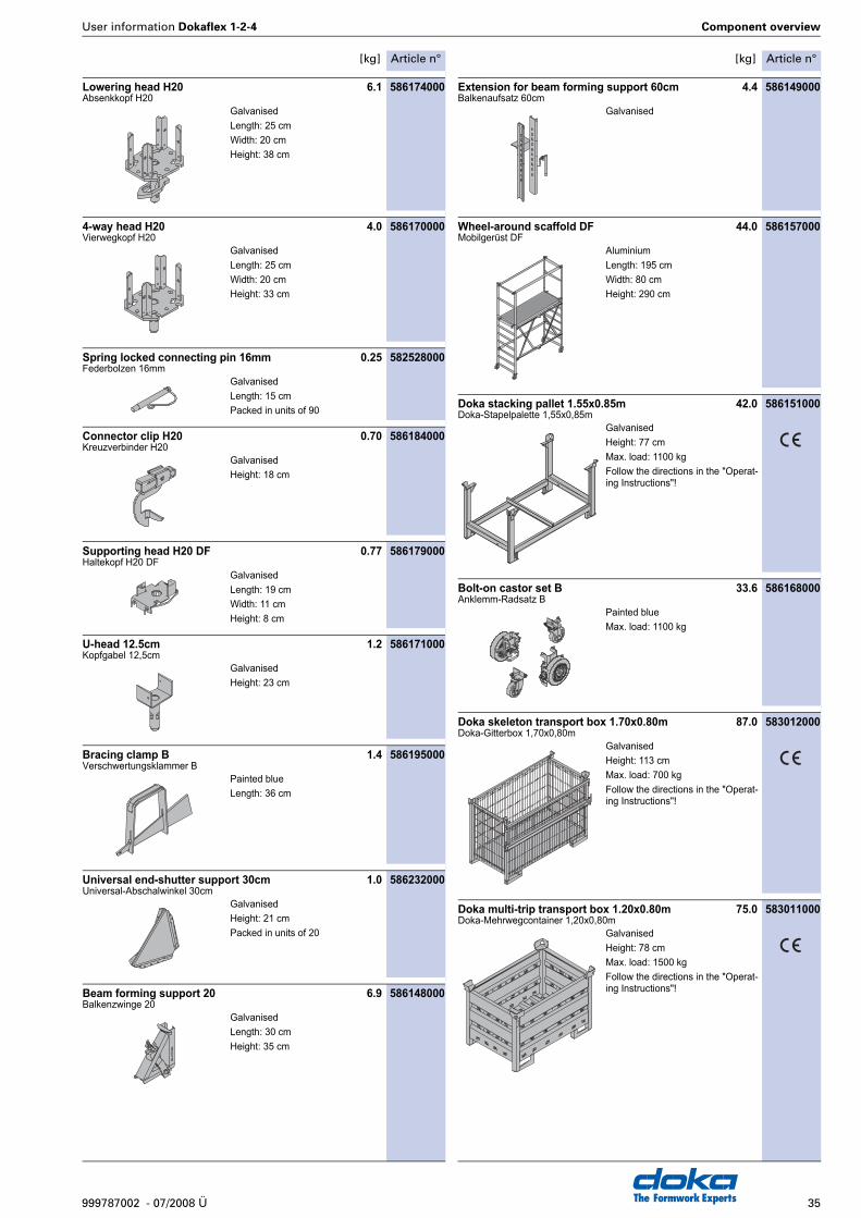
Lowering head H20 6.1 586174000Absenkkopf H20
4-way head H20 4.0 586170000Vierwegkopf H20
Spring locked connecting pin 16mm 0.25 582528000Federbolzen 16mm
Connector clip H20 0.70 586184000Kreuzverbinder H20
Supporting head H20 DF 0.77 586179000Haltekopf H20 DF
U-head 12.5cm 1.2 586171000Kopfgabel 12,5cm
Bracing clamp B 1.4 586195000Verschwertungsklammer B
Universal end-shutter support 30cm 1.0 586232000Universal-Abschalwinkel 30cm
Beam forming support 20 6.9 586148000Balkenzwinge 20
Extension for beam forming support 60cm 4.4 586149000Balkenaufsatz 60cm
Wheel-around scaffold DF 44.0 586157000Mobilgerüst DF
Doka stacking pallet 1.55x0.85m 42.0 586151000Doka-Stapelpalette 1,55x0,85m
Bolt-on castor set B 33.6 586168000Anklemm-Radsatz B
Doka skeleton transport box 1.70x0.80m 87.0 583012000Doka-Gitterbox 1,70x0,80m
Doka multi-trip transport box 1.20x0.80m 75.0 583011000Doka-Mehrwegcontainer 1,20x0,80m
GalvanisedLength: 25 cmWidth: 20 cmHeight: 38 cm
GalvanisedLength: 25 cmWidth: 20 cmHeight: 33 cm
GalvanisedLength: 15 cmPacked in units of 90
GalvanisedHeight: 18 cm
GalvanisedLength: 19 cmWidth: 11 cmHeight: 8 cm
GalvanisedHeight: 23 cm
Painted blueLength: 36 cm
GalvanisedHeight: 21 cmPacked in units of 20
GalvanisedLength: 30 cmHeight: 35 cm
Galvanised
AluminiumLength: 195 cmWidth: 80 cmHeight: 290 cm
GalvanisedHeight: 77 cmMax. load: 1100 kgFollow the directions in the "Operat-ing Instructions"!
Painted blueMax. load: 1100 kg
GalvanisedHeight: 113 cmMax. load: 700 kgFollow the directions in the "Operat-ing Instructions"!
GalvanisedHeight: 78 cmMax. load: 1500 kgFollow the directions in the "Operat-ing Instructions"!

Article n°[kg] Article n°[kg]
36 999787002 - 07/2008 Ü
Component overview User information Dokaflex 1-2-4
The Formwork Experts
Multi-trip transport box partition 0.80m 3.7 583018000Multi-trip transport box partition 1.20m 5.5 583017000Mehrwegcontainer Unterteilung
Alu beam fork H20 2.4 586182000Alu-Trägergabel H20
Stripping lever DF 1.20m 2.7 586158000Ausschalhebel DF 1,20m
Lever extension DF 1.20m 2.0 586159000Hebelverlängerung DF 1,20m
Doka beam H20 top N 2.65m 13.8 189013000Doka beam H20 top N 3.90m 20.0 189017000Doka-Träger H20 top N
Doka beam H20 top P 2.65m 14.3 189703000Doka beam H20 top P 3.90m 20.8 189707000Doka-Träger H20 top P
Dokadur panel 21 200/50cm 11.0 186083000Dokadur panel 21 250/50cm 13.8 186081000Dokadur panel 21 200/50cm BS 11.0 186083100Dokadur panel 21 250/50cm BS 13.8 186081100Dokadur-Paneel 21
Dokadur panel 27 200/50cm 13.5 187170000Dokadur panel 27 250/50cm 16.9 187168000Dokadur panel 27 200/50cm BS 13.5 187170100Dokadur panel 27 250/50cm BS 16.9 187168100Dokadur-Paneel 27
Doka formwork sheet 3-SO 21mm 200/50cm 10.5 186009000Doka formwork sheet 3-SO 21mm 250/50cm 13.1 186011000Doka-Schalungsplatte 3-SO 21mm
Doka formwork sheet 3-SO 27mm 200/50cm 13.0 187009000Doka formwork sheet 3-SO 27mm 250/50cm 16.3 187011000Doka-Schalungsplatte 3-SO 27mm
Stacking strap 50 3.1 586156000Stapelgurt 50
Handrail clamp S 11.5 580470000Schutzgeländerzwinge S
Handrail clamp T 12.3 584381000Schutzgeländerzwinge T
Timber parts varnished yellowSteel parts galvanised
AluminiumPowder-coated yellowLength: 176 cm
Powder-coated yellow
Powder-coated yellow
Varnished yellowPermitted bending moment: 5.0 kNmPerm. shear force: 11.0 kNApproval by Institute of Building Technology, Berlin. Values applica-ble only when formwork beams are upright.
Varnished yellowPermitted bending moment: 5.0 kNmPerm. shear force: 11.0 kNApproval by Institute of Building Technology, Berlin. Values applica-ble only when formwork beams are upright.
High-grade floor-forming panels, 3-ply, 21 mm, with impact-resistant plastic surround.For clean concrete faces with plain surface appearance. Also available for rental.
High-grade floor-forming panels, 3-ply, 27 mm, with impact-resistant plastic surround.For clean concrete faces with plain surface appearance. Also available for rental.
3-SO formwork sheet as per ÖNORM B3023With boil-proof and weatherproof bondingHigh quality MUF synthetic-resin sur-faceA high quality formwork panel for all purposes
3-SO formwork sheet as per ÖNORM B3023With boil-proof and weatherproof bondingHigh quality MUF synthetic-resin sur-faceA high quality formwork panel for all purposes
Powder-coated, bluePerm. strapping force: 40 kN
GalvanisedHeight: 123 - 171 cm
GalvanisedHeight: 122 - 155 cm
Article n°[kg] Article n°[kg]
37999787002 - 07/2008 Ü
User information Dokaflex 1-2-4 Component overview
The Formwork Experts
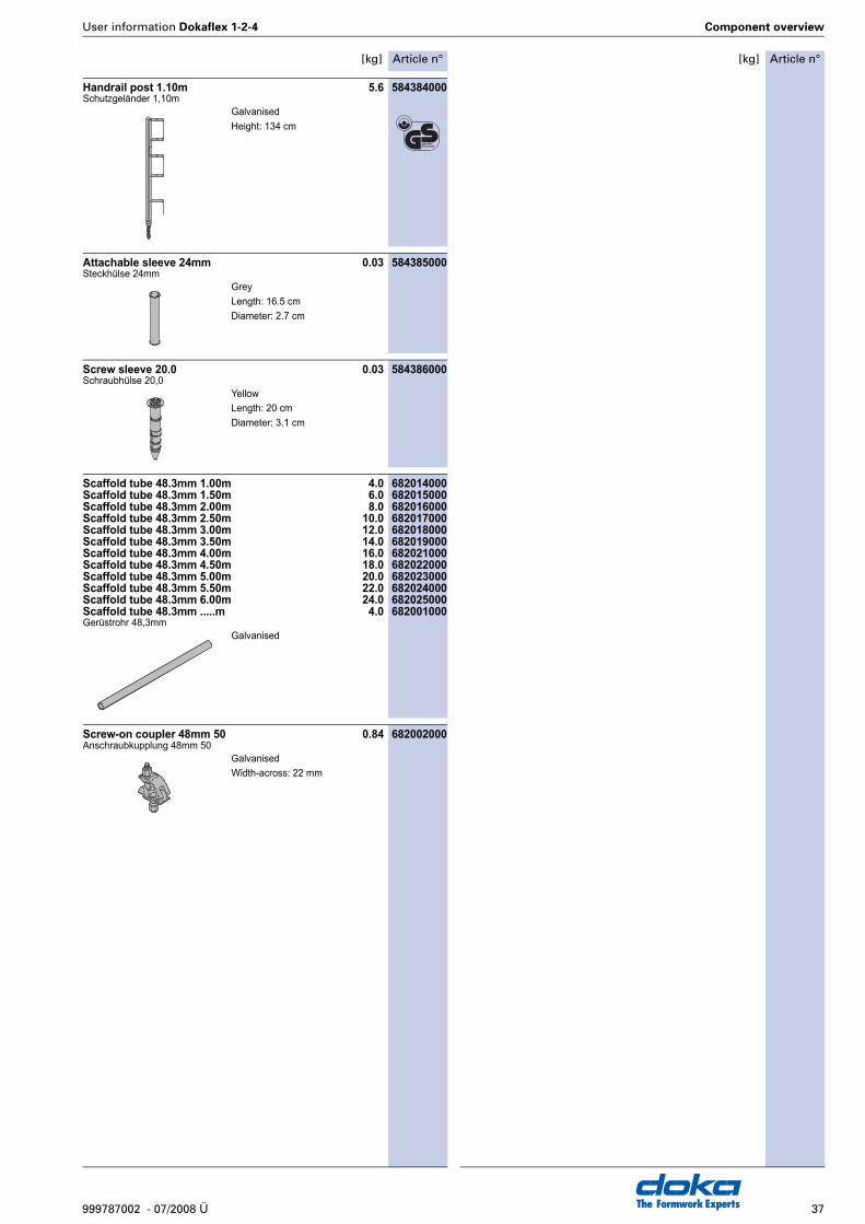
Handrail post 1.10m 5.6 584384000Schutzgeländer 1,10m
Attachable sleeve 24mm 0.03 584385000Steckhülse 24mm
Screw sleeve 20.0 0.03 584386000Schraubhülse 20,0
Scaffold tube 48.3mm 1.00m 4.0 682014000Scaffold tube 48.3mm 1.50m 6.0 682015000Scaffold tube 48.3mm 2.00m 8.0 682016000Scaffold tube 48.3mm 2.50m 10.0 682017000Scaffold tube 48.3mm 3.00m 12.0 682018000Scaffold tube 48.3mm 3.50m 14.0 682019000Scaffold tube 48.3mm 4.00m 16.0 682021000Scaffold tube 48.3mm 4.50m 18.0 682022000Scaffold tube 48.3mm 5.00m 20.0 682023000Scaffold tube 48.3mm 5.50m 22.0 682024000Scaffold tube 48.3mm 6.00m 24.0 682025000Scaffold tube 48.3mm .....m 4.0 682001000Gerüstrohr 48,3mm
Screw-on coupler 48mm 50 0.84 682002000Anschraubkupplung 48mm 50
GalvanisedHeight: 134 cm
GreyLength: 16.5 cmDiameter: 2.7 cm
YellowLength: 20 cmDiameter: 3.1 cm
Galvanised
GalvanisedWidth-across: 22 mm

The Formwork Experts38 999787002 - 07/2008 Ü
User information Dokaflex 1-2-4

User information Dokaflex 1-2-4
39999787002 - 07/2008 Ü The Formwork Experts
The Formwork Experts999787002 - 07/2008 Ü
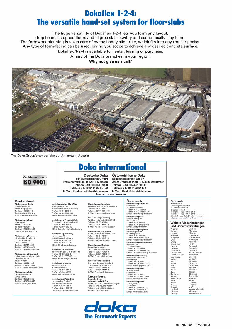
Dokaflex 1-2-4:The versatile hand-set system for floor-slabs
The huge versatility of Dokaflex 1-2-4 lets you form any layout,drop beams, stepped floors and filigree slabs swiftly and economically – by hand.
The formwork planning is taken care of by the handy slide-rule, which fits into any trouser pocket.Any type of form-facing can be used, giving you scope to achieve any desired concrete surface.
Dokaflex 1-2-4 is available for rental, leasing or purchase.At any of the Doka branches in your region.
Why not give us a call?
The Doka Group's central plant at Amstetten, Austria


![Doka Catalogue[1]](https://img.pdfslide.us/doc/110x75/5571f30d49795947648d694d/doka-catalogue1.jpg)