Embed Size (px)
Citation preview
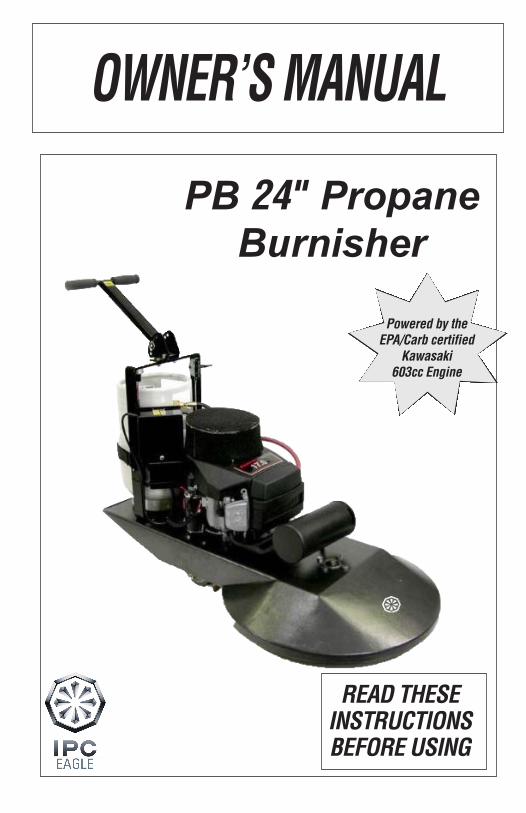
OWNER’S MANUAL
PB 24" Propane Burnisher
9758/8.10
201 COMMERCE DRIVE • MONTGOMERYVILLE, PA 18936
215-393-4700 • 800-331-1423 • FAX 215-393-4800
AZTEC PRODUCTS WARRANTY
Aztec Products, Inc. warrants its products to be free from defects in material and workmanship for aperiod of one year from the date of sale. All engines are warranted by the manufacturers (Honda orKawasaki) for a period of two years when engine maintenance schedules are followed.
The warranty does not apply to damage or failure caused by abuse, misuse, neglect, disassembly,alteration, unauthorized modification or repair, lack of proper maintenance, theft or damage byfreight carriers. The warranty applies to parts, labor, and ground freight only. Aztec is not liable fortransportation to or from repair centers or travel for on-site repairs. Aztec Products, Inc. will notbe liable for incidental or consequential damages arising from the use of any of its products, whetherdefective or not.
Aztec Products, Inc. agrees, at its discretion, to repair or replace at its own expense any product orpart(s) which examination proves to be defective in workmanship or materials provided that thepurchaser notifies Aztec Products, Inc. directly within the warranty period and follows the ReturnGoods Policy. Engine repairs may be performed at engine manufacturer’s service centers. For yourclosest center you may call the following numbers:
Kawasaki 616-949-6500 Honda 800-426-7701
In order to obtain parts warranty, the following procedures must be followed:
1. Customer must call Aztec Products, Inc. for an RGA (Return Goods Authorization) Number.
2. We maintain the serial number, date of shipment or sale, and customer name on each piece ofequipment sold. If you were the purchaser, please reference that information on your request forreplacement or repair. If you purchased the equipment through a distributor, please contact them first.If you are not satisfied, contact Aztec and give us the distributor name, purchase date, and the serialnumber of the product.
3. The defective part must be returned via ground freight prepaid to Aztec Products, Inc. with an RGAnumber accompanied by a copy to the original purchase invoice. Aztec is not responsible for the costof packaging inbound freight, nor inbound freight damage. Pack machine carefully.
4. Only Aztec Products, Inc. or its authorized dealers may make warranty repairs on Aztec Products,Inc. products. Others do so at their own risk and expense.
5. We also offer to do warranty related repairs free of charge at our facility. Arrangements must bemade in advance as outlined above. Wewill not accept freight collect returns or returns that do not indi-cate the RGA number on the packing list.
The need for proper maintenance and care for this product cannot be overstated. Poor maintenance,neglect or abuse can prove to be very expensive.
You have purchased a quality product. Each of its components has been tested and approved for useby Aztec Products, Inc. It is unlikely that you will ever have a warranty claim if you properly maintainour machine.
This warranty is non-transferable.
AZTEC PRODUCTS, INC.201 Commerce Drive • Montgomeryville, PA 18936 • 800-331-1423 • Fax 215-393-4800
READ THESE INSTRUCTIONS BEFORE USING
Powered by the EPA/Carb certified
Kawasaki 603cc Engine
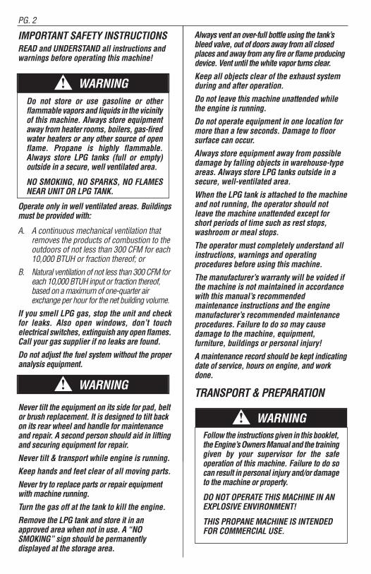
IMPORTANT SAFETY INSTRUCTIONSREAD and UNDERSTAND all instructions and warnings before operating this machine!
Do not store or use gasoline or otherflammable vapors and liquids in the vicinityof this machine. Always store equipmentaway from heater rooms, boilers, gas-firedwater heaters or any other source of openflame. Propane is highly flammable.Always store LPG tanks (full or empty)outside in a secure, well ventilated area.
NO SMOKING, NO SPARKS, NO FLAMESNEAR UNIT OR LPG TANK.
Operate only in well ventilated areas. Buildingsmust be provided with:
A. A continuous mechanical ventilation thatremoves the products of combustion to theoutdoors of not less than 300 CFM for each10,000 BTUH or fraction thereof; or
B. Natural ventilation of not less than 300 CFM foreach 10,000 BTUH input or fraction thereof,based on a maximum of one-quarter airexchange per hour for the net building volume.
If you smell LPG gas, stop the unit and check for leaks. Also open windows, don’t touchelectrical switches, extinguish any open flames.Call your gas supplier if no leaks are found.
Do not adjust the fuel system without the properanalysis equipment.
Never tilt the equipment on its side for pad, beltor brush replacement. It is designed to tilt backon its rear wheel and handle for maintenanceand repair. A second person should aid in liftingand securing equipment for repair.
Never tilt & transport while engine is running.
Keep hands and feet clear of all moving parts.
Never try to replace parts or repair equipmentwith machine running.
Turn the gas off at the tank to kill the engine.
Remove the LPG tank and store it in anapproved area when not in use. A “NOSMOKING” sign should be permanentlydisplayed at the storage area.
Always vent an over-full bottle using the tank’sbleed valve, out of doors away from all closedplaces and away from any fire or flame producingdevice. Vent until the white vapor turns clear.
Keep all objects clear of the exhaust systemduring and after operation.
Do not leave this machine unattended whilethe engine is running.
Do not operate equipment in one location formore than a few seconds. Damage to floorsurface can occur.
Always store equipment away from possibledamage by falling objects in warehouse-typeareas. Always store LPG tanks outside in asecure, well-ventilated area.
When the LPG tank is attached to the machineand not running, the operator should notleave the machine unattended except forshort periods of time such as rest stops,washroom or meal stops.
The operator must completely understand allinstructions, warnings and operatingprocedures before using this machine.
The manufacturer’s warranty will be voided ifthe machine is not maintained in accordancewith this manual’s recommendedmaintenance instructions and the enginemanufacturer’s recommended maintenanceprocedures. Failure to do so may causedamage to the machine, equipment,furniture, buildings or personal injury!
A maintenance record should be kept indicatingdate of service, hours on engine, and workdone.
TRANSPORT & PREPARATION
Follow the instructions given in this booklet,the Engine’s Owners Manual and the traininggiven by your supervisor for the safeoperation of this machine. Failure to do socan result in personal injury and/or damageto the machine or property.
DO NOT OPERATE THIS MACHINE IN ANEXPLOSIVE ENVIRONMENT!
THIS PROPANE MACHINE IS INTENDEDFOR COMMERCIAL USE.
PG. 2 THE RELIANT PG. 15
NOTES
WARNING!
WARNING!
WARNING!
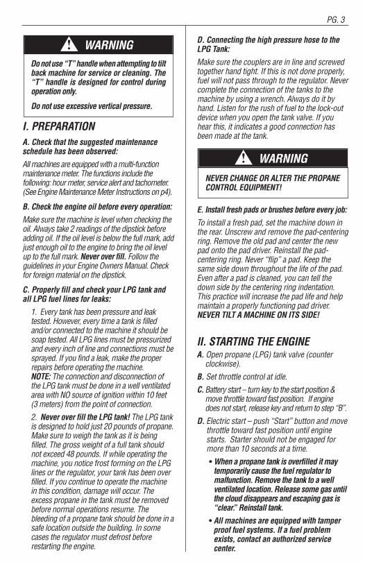
Do not use “T” handle when attempting to tiltback machine for service or cleaning. The“T” handle is designed for control duringoperation only.
Do not use excessive vertical pressure.
I. PREPARATIONA. Check that the suggested maintenanceschedule has been observed:
All machines are equipped with a multi-functionmaintenance meter. The functions include thefollowing: hour meter, service alert and tachometer.(See Engine Maintenance Meter Instructions on p4).
B. Check the engine oil before every operation:
Make sure the machine is level when checking theoil. Always take 2 readings of the dipstick beforeadding oil. If the oil level is below the full mark, addjust enough oil to the engine to bring the oil levelup to the full mark. Never over fill. Follow theguidelines in your Engine Owners Manual. Checkfor foreign material on the dipstick.
C. Properly fill and check your LPG tank andall LPG fuel lines for leaks:
1. Every tank has been pressure and leaktested. However, every time a tank is filledand/or connected to the machine it should besoap tested. All LPG lines must be pressurizedand every inch of line and connections must besprayed. If you find a leak, make the properrepairs before operating the machine. NOTE: The connection and disconnection ofthe LPG tank must be done in a well ventilatedarea with NO source of ignition within 10 feet(3 meters) from the point of connection.
2. Never over fill the LPG tank! The LPG tankis designed to hold just 20 pounds of propane.Make sure to weigh the tank as it is beingfilled. The gross weight of a full tank shouldnot exceed 48 pounds. If while operating themachine, you notice frost forming on the LPGlines or the regulator, your tank has been overfilled. If you continue to operate the machinein this condition, damage will occur. Theexcess propane in the tank must be removedbefore normal operations resume. Thebleeding of a propane tank should be done in asafe location outside the building. In somecases the regulator must defrost beforerestarting the engine.
D. Connecting the high pressure hose to theLPG Tank:
Make sure the couplers are in line and screwedtogether hand tight. If this is not done properly,fuel will not pass through to the regulator. Nevercomplete the connection of the tanks to themachine by using a wrench. Always do it byhand. Listen for the rush of fuel to the lock-outdevice when you open the tank valve. If youhear this, it indicates a good connection hasbeen made at the tank.
NEVER CHANGE OR ALTER THE PROPANE CONTROL EQUIPMENT!
E. Install fresh pads or brushes before every job:
To install a fresh pad, set the machine down inthe rear. Unscrew and remove the pad-centeringring. Remove the old pad and center the newpad onto the pad driver. Reinstall the pad-centering ring. Never “flip” a pad. Keep thesame side down throughout the life of the pad.Even after a pad is cleaned, you can tell thedown side by the centering ring indentation.This practice will increase the pad life and helpmaintain a properly functioning pad driver.NEVER TILT A MACHINE ON ITS SIDE!
II. STARTING THE ENGINEA. Open propane (LPG) tank valve (counterclockwise).
B. Set throttle control at idle.
C. Battery start – turn key to the start position &move throttle toward fast position. If enginedoes not start, release key and return to step “B”.
D. Electric start – push “Start” button and movethrottle toward fast position until enginestarts. Starter should not be engaged formore than 10 seconds at a time.
• When a propane tank is overfilled it maytemporarily cause the fuel regulator tomalfunction. Remove the tank to a wellventilated location. Release some gas untilthe cloud disappears and escaping gas is “clear”. Reinstall tank.
• All machines are equipped with tamperproof fuel systems. If a fuel problemexists, contact an authorized servicecenter.
PG. 3PG. 14 THE RELIANT
NOTES WARNING!
WARNING!
PG. 4
• Propane tanks should be removed &stored in a protected off site area.
III. OPERATIONProvide and use ear protection during operation.
Never let an untrained person operate orperform repairs on the machine. They may hurtthemselves, damage the floor or theequipment.
Engine speed not to exceed 3400 RPM.
This machine is not suitable for picking uphazardous dust.
Do not use on surfaces with a gradientexceeding 2%.
IV. STOPPING THE ENGINETurn the propane tank valve clockwise to a closedposition and turn the key OFF.
NOTE: The exhaust system will be very hot andtakes several minutes to cool, so keep yourselfand all materials clear.
V. PROCEDURESFollow machine (straight ahead) at moderatewalking speed. Keep moving.• Do not operate the machine in one location
for more than a few seconds — it willdamage — “burn” the finish.
• When operation is completed remove tankand store in a secure, protected off site(preferably outdoor) location.
• Do not use for scrubbing operations.
• Never tilt back machine to maintenanceposition while engine is running.
• Never reach under protective shroud whenengine is running.
VI. MAINTENANCEA. Machine & engine maintenance
1. Refer to engine manufacturer’s ownersmanual and comply completely with theinstructions. Change the oil and filter accordingto the Engine Owners Manual.
2. Keep a good service log on each machinewith the date, hour meter reading, type(s) ofservice performed and the name of the personwho performed them.3. Clean the entire unit after each use. When
cleaning the unit, check for possible loose nutsand bolts.
B. Engine maintenance meter
This multi-function meter acts as a preventivemaintenance tool, which benefits you withincreased fuel economy, less down-time andlonger engine life. The meter’s displays are:
Hour Meter:Displays total run hours whenmachine is off.
Tachometer: Indicates engine RPM duringoperation.
Service Alert: The display flashes to alert you tolube and change the oil at 25 hour intervals. Theservice alert only flashes during operation and itwarns you to change the oil for only two hours.After the two hours is reached, the alert willautomatically reset to the next 25 hour interval.Therefore, it is recommended that a separatemaintenance log be kept to track oil changes.
Remember that being safe is a full-time, everyday job. Follow all information posted on themachine and the LPG tank.
Never allow anyone to operate this machinewho has not read or cannot understand thegiven instructions.
C. Troubleshooting the electrical system
1. Check all wire connections for obviousproblems. Remove LPG tank, then removebattery box cover. Check all connections visiblyand physically. If any “loose”, damaged orunconnected wires are noticed, replace orrepair as needed.
2. Check the battery posts and wires. Alwayswear a face shield, safety glasses andprotective clothing when working around abattery! The gases can be explosive and the acidis highly corrosive to metals, cloth and ALLHUMAN TISSUE (skin, eyes, etc.) If the batterypost(s) are corroded, remove the wires and cleanposts and wires. Applying some axle grease onthe posts of the battery after they are cleaned willslow down the battery corrosion process.
If nothing obvious is noted, a more detailedinvestigation is warranted. Before any suchtroubleshooting begins, the following thingsshould be done:
a. Replace propane LPG tank with one froma machine that runs.
b. Charge the battery or provide an absolutesource of 12 volt DC power capable of 50
THE RELIANT PG. 13
NOTES
PG. 5
amperes total output. (A pair of goodjumper cables from your car or truck batterywill suffice.) Equip yourself with aninexpensive 12 volt test light.
c. If the trouble seems to be in the electricalcontrol equipment, you may wish todisconnect the starter from the system soas to check the system without spinningthe engine.
d. Battery rundown. A common problemis letting the battery run down. Whatusually happens is that it takes the crew afew jobs to get used to the whole system,so the machine is stopped and startedquite often. Key left in on position, whenengine is turned off, will result in batteryrunning down – dying.
D. Belt Inspection & Replacement
Inspection
• Fold T-Handle to forward position• Tilt machine back on rear of body & handle• If belt is worn, cracked or shredding, beltneeds to be replaced.
VII. PAD DRIVE FACING, BELT,IDLER PULLEY, ORDRIVE SHAFT REPLACEMENT
A. Adjust the handle to enable the buffer to standon rear wheels.• Handle must be in shipping (forward)
position to insure stability in the “tiltback” position. A second person shouldaide in the lift and to secure the bufferwhile being serviced.
• Do not use “T” handle when attempting totilt back machine for service or cleaning.“T” handle is designed for control duringoperation — Do not use excessivevertical pressure.
B. Remove pad drive nut & pad centering deviceand four (4) bolts (9/16" wrench).
C. Remove pad drive. (Replace if worn.)D. Remove idler pulley. (Replace if worn.)E. Remove belt(s). (Replace if worn.)F. To remove driveshaft unit: Remove retainingbolt & clip — pull driveshaft out of housing —use of a slide hammer may assist in removal (donot pry with crow bar.) While drive shaft isremoved, spin bearings. If roughness is felt, bearing replacement may be necessary.G. To reassemble, reverse order of all steps takenpreviously.
KAWASAKI ENGINESTune-up Specifications
ITEM SPECIFICATIONS
Ignition Timing Unadjustable
Spark Plugs: Champion – RCJ8YGap 0.75 mm (0.30 in)
Low Idle Speed 1500 RPM
High Idle Speed 3400 RPM
Valve Clearance IN: 0.10-0.15 mm(0.004-0.006 in)EX: 0.10-0.15 mm(0.004-0.006 in)
Other Specifications No other adjustment needed
NOTE: High and low idle speeds may varydepending on the equipment on which the engine is used. Refer to the equipment specifications.
Engine Oil
Check the engine oil daily before starting the engineotherwise shortage of the engine oil may causeserious damage to the engine such as seizure.
• Place the engine on a level surface. Clean thearea around the oil gauge before removing it.
• Remove the oil gauge and wipe it with a cleancloth.
• Pour the oil slowly to “FULL” mark on the oilgauge.
• Insert the oil gauge into the tube WITHOUTSCREWING IT IN.
• Remove the oil gauge to check the oil level.The oil level should be between “ADD” and“FULL” marks. Do not overfill.
• Install and tighten the oil gauge.
The following engine oils are recommended:
API Service Classification: SF, SG, SH, or SJ.
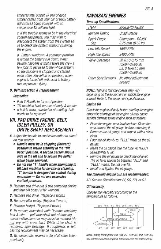
Oil Viscosity
Choose the viscosity according to the temperature as follows:
NOTE: Using multi grade oils (5W-20, 10W-30, and 10W-40)will increase oil consumption. Check oil level more frequently.
-20˚C -10˚C 0˚C 10˚C 20˚C 30˚C 40˚C
-4˚F 14˚F 32˚F 50˚F 68˚F 88˚F 104˚F
SAE5W-20
SAE30
SAE40
SAE10W-30/SAE10W-40
PG. 12 THE RELIANT
As our customer, you are aware that the design and construction ofthis product are both innovative and unique. Since this is true, in orderto troubleshoot our equipment, we rely heavily on returned defectiveor failed parts so that we can examine the causes of failure. While thismay at first seem to be an inconvenience, ultimately you benefit fromsafer, better designed machine components. Please give us the opportunity to serve you better by following these RGA (Return GoodsAuthorization) rules.
1. We maintain the serial number, date of shipment or sale, and customer name on each piece of equipment sold. If you were thepurchaser, please reference that information on your request forreplacement or repair. If you purchased the equipment through adealer, please include the company name, the date, and the serialnumber of the product.
2. Ask for an RGA number when you are ordering the replacementpart. Return the failed part within 14 days, freight prepaid, exactly
as it was at the time of failure. Our inspection and evaluation willattempt to determine the probable cause of failure.
3. If our inspection reveals that the failed part was defective, we willcredit your account for the entire amount of the part including yourcost of return freight, but not packaging expense. Whenincomplete parts are returned for credit, their condition or state ofincompletion will be assessed against the credit claim.
4. We will not accept freight collect returns or returns that do not indicate the RGA # on the packing list.
Your satisfaction is extremely important to us. We intend to be rea-sonable on any matter that is related to our warranty service or otherwear-relatedproblemswhich our customers feel need attention. Pleasehelp us to help you. Before assuming that a part is defective, checkthe repair manual to see if the problem might be something that youor one of your employees might be capable of correcting. If it is not,follow the above policy and depend on us to respond quickly andresponsibly.
PROTECT YOUR WARRANTY!Read carefully, any questions regarding the care and safety of this unit, please
CALL (800) 331-1423
!!
PG. 6
Engine Oil Capacity
FH381V, FH500V, FH541V: Fill to 1.5 L (1.6 USqt.) when oil filter is not removed. Fill to 1.7 L (1.8US qt.) when oil filter is removed.
Oil Change
Change oil after first 8 hours of operation.Thereafter change oil every 50 hours.• Run the engine to warm oil.• Be sure the engine (equipment) is level.• Stop the engine.• Open the oil drain valve and drain the oil intosuitable container while engine is warm.
WARNING!Hot engine oil can cause severe burns.Allow engine temperature to drop from hot to warm level before draining and handling oil.
Oil Drain Plug• Close the oil drain valve.• Remove oil gauge and refill with fresh oil(See “Recommended Oils” on p5).• Check the oil level (see “Preparation” on p3for oil level check).
Oil Filter Change• Change the oil filter every 100 hours ofoperation.
WARNING!Hot engine oil can cause severe burns.Allow engine temperature to drop from hotto warm level before attempting to removeoil filter.
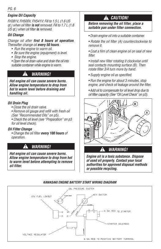
Before removing the oil filter, place asuitable pan under filter connection.
• Drain engine oil into a suitable container.
• Rotate the oil filter (A) counterclockwise toremove it.
• Coat a film of clean engine oil on seal of newfilter.
• Install new filter rotating it clockwise untilseal contacts mounting surface (B). Thenrotate filter 3/4 turn more by hand.
• Supply engine oil as specified.
• Run the engine for about 3 minutes, stopengine, and check oil leakage around the filter.
• Add oil to compensate for oil level drop due tooil filter capacity (See “Oil Level Check” on p3).
WARNING!Engine oil is a toxic substance. Dispose of used oil properly. Contact your localauthorities for approved disposal methodsor possible recycling.
!
KAWASAKI ENGINE BATTERY START WIRING DIAGRAM
THE RELIANT PG. 11
CAUTION!!
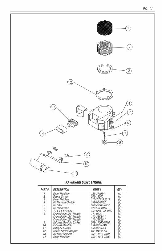
KAWASAKI 603cc ENGINE
PART # DESCRIPTION PART # QTY1. Foam Hat Filter 186-271964 (1)2. Debris Screen 309-18540 (1)3. Foam Hat Seal 175-7.75*9.25*1 (1)4. Oil Pressure Switch 152-N3-0082 (1)5. Oil Filter 309-49065-7007 (1)6. Oil Drain Valve 312-504-0185 (1)7. 1 / 4 x 1 1 / 4 Key 199-NHNT-SE UND (1)8. Crank Pulley (21” Model) 172-BS32 (1)
Crank Pulley (24” Model) 172-2BK34-1 (1)Crank Pulley (27” Model) 172-2BK28-1 (1)
9. Exhaust Manifold Gasket 309-11060-7016 (2)10. Exhaust Manifold 152-603-MAN (1)11. Catalytic Muffler 152-603-MUF (1)12. Debris Screen Adapter 283-040-2250 (1)13. Air Filter Element 309-11013-7049 (1)14. Foam Pre Filter 309-11013-7046 (1)
PG. 7
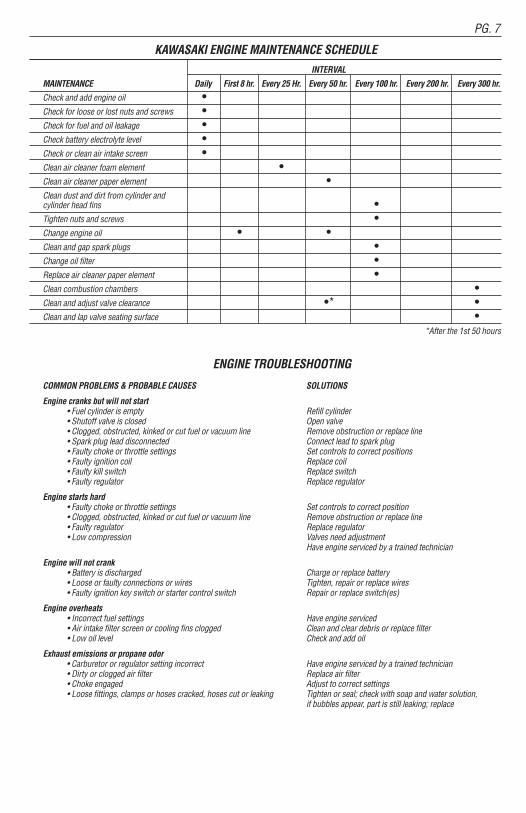
KAWASAKI ENGINE MAINTENANCE SCHEDULEINTERVAL
MAINTENANCE Daily First 8 hr. Every 25 Hr. Every 50 hr. Every 100 hr. Every 200 hr. Every 300 hr.
Check and add engine oil •Check for loose or lost nuts and screws •Check for fuel and oil leakage •Check battery electrolyte level •Check or clean air intake screen •Clean air cleaner foam element •Clean air cleaner paper element •Clean dust and dirt from cylinder and cylinder head fins •Tighten nuts and screws •Change engine oil • •Clean and gap spark plugs •Change oil filter •Replace air cleaner paper element •Clean combustion chambers •Clean and adjust valve clearance •* •Clean and lap valve seating surface •
*After the 1st 50 hours
ENGINE TROUBLESHOOTING
COMMON PROBLEMS & PROBABLE CAUSES SOLUTIONS
Engine cranks but will not start• Fuel cylinder is empty Refill cylinder• Shutoff valve is closed Open valve• Clogged, obstructed, kinked or cut fuel or vacuum line Remove obstruction or replace line• Spark plug lead disconnected Connect lead to spark plug• Faulty choke or throttle settings Set controls to correct positions• Faulty ignition coil Replace coil• Faulty kill switch Replace switch• Faulty regulator Replace regulator
Engine starts hard• Faulty choke or throttle settings Set controls to correct position• Clogged, obstructed, kinked or cut fuel or vacuum line Remove obstruction or replace line• Faulty regulator Replace regulator• Low compression Valves need adjustment
Have engine serviced by a trained technician
Engine will not crank• Battery is discharged Charge or replace battery• Loose or faulty connections or wires Tighten, repair or replace wires• Faulty ignition key switch or starter control switch Repair or replace switch(es)
Engine overheats• Incorrect fuel settings Have engine serviced• Air intake filter screen or cooling fins clogged Clean and clear debris or replace filter • Low oil level Check and add oil
Exhaust emissions or propane odor• Carburetor or regulator setting incorrect Have engine serviced by a trained technician• Dirty or clogged air filter Replace air filter• Choke engaged Adjust to correct settings• Loose fittings, clamps or hoses cracked, hoses cut or leaking Tighten or seal; check with soap and water solution,
if bubbles appear, part is still leaking; replace
PG. 10 THE RELIANT
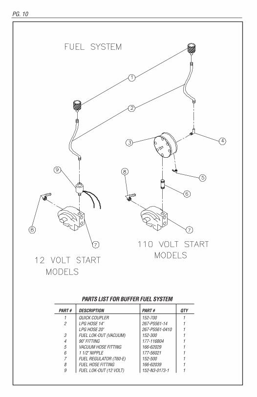
PARTS LIST FOR BUFFER FUEL SYSTEM
PART # DESCRIPTION PART # QTY
1 QUICK COUPLER 152-700 12 LPG HOSE 14" 267-P5561-14 1
LPG HOSE 20" 267-P5561-0410 13 FUEL LOK-OUT (VACUUM) 152-300 14 90˚ FITTING 177-116B04 15 VACUUM HOSE FITTING 166-62029 16 1 1/2" NIPPLE 177-56021 17 FUEL REGULATOR (T60-E) 152-500 18 FUEL HOSE FITTING 166-62039 19 FUEL LOK-OUT (12 VOLT) 152-N3-0173-1 1
PG. 8
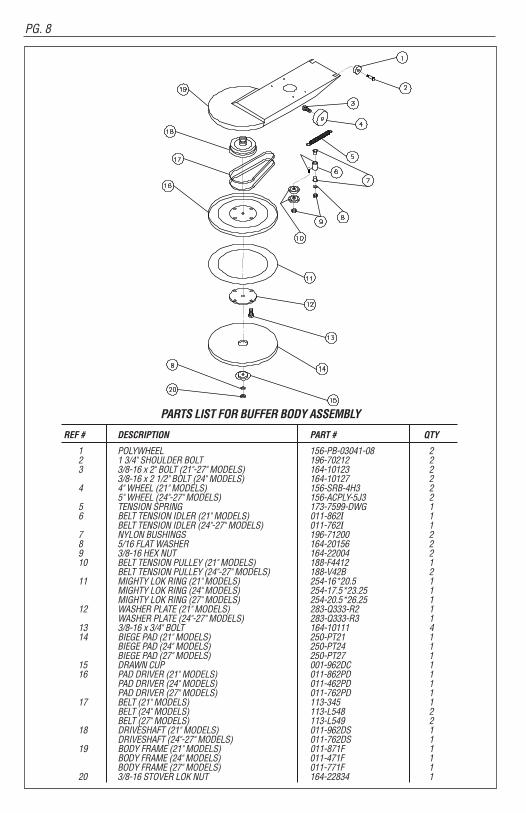
PARTS LIST FOR BUFFER BODY ASSEMBLY
REF # DESCRIPTION PART # QTY
1 POLYWHEEL 156-PB-03041-08 22 1 3/4" SHOULDER BOLT 196-70212 2 3 3/8-16 x 2" BOLT (21"-27" MODELS) 164-10123 2
3/8-16 x 2 1/2" BOLT (24" MODELS) 164-10127 24 4" WHEEL (21" MODELS) 156-SRB-4H3 2
5" WHEEL (24"-27" MODELS) 156-ACPLY-5J3 25 TENSION SPRING 173-7599-DWG 16 BELT TENSION IDLER (21" MODELS) 011-862I 1
BELT TENSION IDLER (24"-27" MODELS) 011-762I 17 NYLON BUSHINGS 196-71200 28 5/16 FLAT WASHER 164-20156 29 3/8-16 HEX NUT 164-22004 210 BELT TENSION PULLEY (21" MODELS) 188-F4412 1
BELT TENSION PULLEY (24"-27" MODELS) 188-V42B 211 MIGHTY LOK RING (21" MODELS) 254-16*20.5 1
MIGHTY LOK RING (24" MODELS) 254-17.5*23.25 1MIGHTY LOK RING (27" MODELS) 254-20.5*26.25 1
12 WASHER PLATE (21" MODELS) 283-Q333-R2 1WASHER PLATE (24"-27" MODELS) 283-Q333-R3 1
13 3/8-16 x 3/4" BOLT 164-10111 414 BIEGE PAD (21" MODELS) 250-PT21 1
BIEGE PAD (24" MODELS) 250-PT24 1BIEGE PAD (27" MODELS) 250-PT27 1
15 DRAWN CUP 001-962DC 116 PAD DRIVER (21" MODELS) 011-862PD 1
PAD DRIVER (24" MODELS) 011-462PD 1PAD DRIVER (27" MODELS) 011-762PD 1
17 BELT (21" MODELS) 113-345 1BELT (24" MODELS) 113-L548 2BELT (27" MODELS) 113-L549 2
18 DRIVESHAFT (21" MODELS) 011-962DS 1DRIVESHAFT (24"-27" MODELS) 011-762DS 1
19 BODY FRAME (21" MODELS) 011-871F 1BODY FRAME (24" MODELS) 011-471F 1BODY FRAME (27" MODELS) 011-771F 1
20 3/8-16 STOVER LOK NUT 164-22834 1
THE RELIANT PG. 9
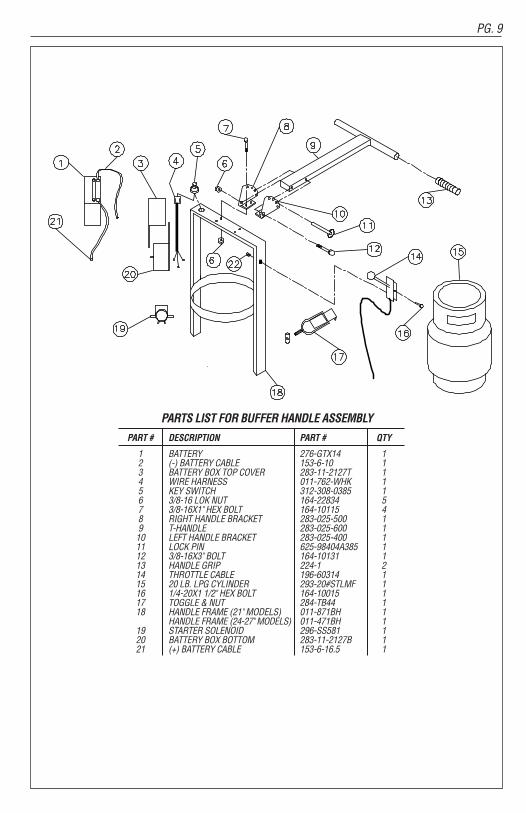
PARTS LIST FOR BUFFER HANDLE ASSEMBLY
PART # DESCRIPTION PART # QTY
1 BATTERY 276-GTX14 12 (-) BATTERY CABLE 153-6-10 13 BATTERY BOX TOP COVER 283-11-2127T 14 WIRE HARNESS 011-762-WHK 15 KEY SWITCH 312-308-0385 16 3/8-16 LOK NUT 164-22834 57 3/8-16X1" HEX BOLT 164-10115 48 RIGHT HANDLE BRACKET 283-025-500 19 T-HANDLE 283-025-600 110 LEFT HANDLE BRACKET 283-025-400 111 LOCK PIN 625-98404A385 112 3/8-16X3" BOLT 164-10131 113 HANDLE GRIP 224-1 214 THROTTLE CABLE 196-60314 115 20 LB. LPG CYLINDER 293-20#STLMF 116 1/4-20X1 1/2" HEX BOLT 164-10015 117 TOGGLE & NUT 284-TB44 118 HANDLE FRAME (21" MODELS) 011-871BH 1
HANDLE FRAME (24-27" MODELS) 011-471BH 119 STARTER SOLENOID 296-SS581 120 BATTERY BOX BOTTOM 283-11-2127B 121 (+) BATTERY CABLE 153-6-16.5 1
PG. 8 THE RELIANT
PARTS LIST FOR BUFFER BODY ASSEMBLY
REF # DESCRIPTION PART # QTY
1 POLYWHEEL 156-PB-03041-08 22 1 3/4" SHOULDER BOLT 196-70212 2 3 3/8-16 x 2" BOLT (21"-27" MODELS) 164-10123 2
3/8-16 x 2 1/2" BOLT (24" MODELS) 164-10127 24 4" WHEEL (21" MODELS) 156-SRB-4H3 2
5" WHEEL (24"-27" MODELS) 156-ACPLY-5J3 25 TENSION SPRING 173-7599-DWG 16 BELT TENSION IDLER (21" MODELS) 011-862I 1
BELT TENSION IDLER (24"-27" MODELS) 011-762I 17 NYLON BUSHINGS 196-71200 28 5/16 FLAT WASHER 164-20156 29 3/8-16 HEX NUT 164-22004 210 BELT TENSION PULLEY (21" MODELS) 188-F4412 1
BELT TENSION PULLEY (24"-27" MODELS) 188-V42B 211 MIGHTY LOK RING (21" MODELS) 254-16*20.5 1
MIGHTY LOK RING (24" MODELS) 254-17.5*23.25 1MIGHTY LOK RING (27" MODELS) 254-20.5*26.25 1
12 WASHER PLATE (21" MODELS) 283-Q333-R2 1WASHER PLATE (24"-27" MODELS) 283-Q333-R3 1
13 3/8-16 x 3/4" BOLT 164-10111 414 BIEGE PAD (21" MODELS) 250-PT21 1
BIEGE PAD (24" MODELS) 250-PT24 1BIEGE PAD (27" MODELS) 250-PT27 1
15 DRAWN CUP 001-962DC 116 PAD DRIVER (21" MODELS) 011-862PD 1
PAD DRIVER (24" MODELS) 011-462PD 1PAD DRIVER (27" MODELS) 011-762PD 1
17 BELT (21" MODELS) 113-345 1BELT (24" MODELS) 113-L548 2BELT (27" MODELS) 113-L549 2
18 DRIVESHAFT (21" MODELS) 011-962DS 1DRIVESHAFT (24"-27" MODELS) 011-762DS 1
19 BODY FRAME (21" MODELS) 011-871F 1BODY FRAME (24" MODELS) 011-471F 1BODY FRAME (27" MODELS) 011-771F 1
20 3/8-16 STOVER LOK NUT 164-22834 1
PG. 9
PARTS LIST FOR BUFFER HANDLE ASSEMBLY
PART # DESCRIPTION PART # QTY
1 BATTERY 276-GTX14 12 (-) BATTERY CABLE 153-6-10 13 BATTERY BOX TOP COVER 283-11-2127T 14 WIRE HARNESS 011-762-WHK 15 KEY SWITCH 312-308-0385 16 3/8-16 LOK NUT 164-22834 57 3/8-16X1" HEX BOLT 164-10115 48 RIGHT HANDLE BRACKET 283-025-500 19 T-HANDLE 283-025-600 110 LEFT HANDLE BRACKET 283-025-400 111 LOCK PIN 625-98404A385 112 3/8-16X3" BOLT 164-10131 113 HANDLE GRIP 224-1 214 THROTTLE CABLE 196-60314 115 20 LB. LPG CYLINDER 293-20#STLMF 116 1/4-20X1 1/2" HEX BOLT 164-10015 117 TOGGLE & NUT 284-TB44 118 HANDLE FRAME (21" MODELS) 011-871BH 1
HANDLE FRAME (24-27" MODELS) 011-471BH 119 STARTER SOLENOID 296-SS581 120 BATTERY BOX BOTTOM 283-11-2127B 121 (+) BATTERY CABLE 153-6-16.5 1
THE RELIANT PG. 7
KAWASAKI ENGINE MAINTENANCE SCHEDULEINTERVAL
MAINTENANCE Daily First 8 hr. Every 25 Hr. Every 50 hr. Every 100 hr. Every 200 hr. Every 300 hr.
Check and add engine oil •Check for loose or lost nuts and screws •Check for fuel and oil leakage •Check battery electrolyte level •Check or clean air intake screen •Clean air cleaner foam element •Clean air cleaner paper element •Clean dust and dirt from cylinder and cylinder head fins •Tighten nuts and screws •Change engine oil • •Clean and gap spark plugs •Change oil filter •Replace air cleaner paper element •Clean combustion chambers •Clean and adjust valve clearance •* •Clean and lap valve seating surface •
*After the 1st 50 hours
ENGINE TROUBLESHOOTING
COMMON PROBLEMS & PROBABLE CAUSES SOLUTIONS
Engine cranks but will not start• Fuel cylinder is empty Refill cylinder• Shutoff valve is closed Open valve• Clogged, obstructed, kinked or cut fuel or vacuum line Remove obstruction or replace line• Spark plug lead disconnected Connect lead to spark plug• Faulty choke or throttle settings Set controls to correct positions• Faulty ignition coil Replace coil• Faulty kill switch Replace switch• Faulty regulator Replace regulator
Engine starts hard• Faulty choke or throttle settings Set controls to correct position• Clogged, obstructed, kinked or cut fuel or vacuum line Remove obstruction or replace line• Faulty regulator Replace regulator• Low compression Valves need adjustment
Have engine serviced by a trained technician
Engine will not crank• Battery is discharged Charge or replace battery• Loose or faulty connections or wires Tighten, repair or replace wires• Faulty ignition key switch or starter control switch Repair or replace switch(es)
Engine overheats• Incorrect fuel settings Have engine serviced• Air intake filter screen or cooling fins clogged Clean and clear debris or replace filter • Low oil level Check and add oil
Exhaust emissions or propane odor• Carburetor or regulator setting incorrect Have engine serviced by a trained technician• Dirty or clogged air filter Replace air filter• Choke engaged Adjust to correct settings• Loose fittings, clamps or hoses cracked, hoses cut or leaking Tighten or seal; check with soap and water solution,
if bubbles appear, part is still leaking; replace
PG. 10
PARTS LIST FOR BUFFER FUEL SYSTEM
PART # DESCRIPTION PART # QTY
1 QUICK COUPLER 152-700 12 LPG HOSE 14" 267-P5561-14 1
LPG HOSE 20" 267-P5561-0410 13 FUEL LOK-OUT (VACUUM) 152-300 14 90˚ FITTING 177-116B04 15 VACUUM HOSE FITTING 166-62029 16 1 1/2" NIPPLE 177-56021 17 FUEL REGULATOR (T60-E) 152-500 18 FUEL HOSE FITTING 166-62039 19 FUEL LOK-OUT (12 VOLT) 152-N3-0173-1 1
!!
PG. 6 THE RELIANT
Engine Oil Capacity
FH381V, FH500V, FH541V: Fill to 1.5 L (1.6 USqt.) when oil filter is not removed. Fill to 1.7 L (1.8US qt.) when oil filter is removed.
Oil Change
Change oil after first 8 hours of operation.Thereafter change oil every 50 hours.• Run the engine to warm oil.• Be sure the engine (equipment) is level.• Stop the engine.• Open the oil drain valve and drain the oil intosuitable container while engine iswarm.
WARNING!Hot engine oil can cause severe burns.Allow engine temperature to drop fromhot to warm level before draining and handling oil.
Oil Drain Plug• Close the oil drain valve.• Remove oil gauge and refill with fresh oil(See “Recommended Oils” on p5).• Check the oil level (see “Preparation” on p3for oil level check).
Oil Filter Change• Change the oil filter every 100 hours ofoperation.
WARNING!Hot engine oil can cause severe burns.Allow engine temperature to drop from hotto warm level before attempting to removeoil filter.
Before removing the oil filter, place asuitable pan under filter connection.
• Drain engine oil into a suitable container.
• Rotate the oil filter (A) counterclockwise toremove it.
• Coat a film of clean engine oil on seal of newfilter.
• Install new filter rotating it clockwise untilseal contacts mounting surface (B). Thenrotate filter 3/4 turn more by hand.
• Supply engine oil as specified.
• Run the engine for about 3 minutes, stopengine, and check oil leakage around the filter.
• Add oil to compensate for oil level drop due tooil filter capacity (See “Oil Level Check” on p3).
WARNING!Engine oil is a toxic substance. Dispose of used oil properly. Contact your localauthorities for approved disposal methodsor possible recycling.
!
KAWASAKI ENGINE BATTERY START WIRING DIAGRAM
PG. 11
CAUTION!!
KAWASAKI 603cc ENGINE
PART # DESCRIPTION PART # QTY1. Foam Hat Filter 186-271964 (1)2. Debris Screen 309-18540 (1)3. Foam Hat Seal 175-7.75*9.25*1 (1)4. Oil Pressure Switch 152-N3-0082 (1)5. Oil Filter 309-49065-7007 (1)6. Oil Drain Valve 312-504-0185 (1)7. 1 / 4 x 1 1 / 4 Key 199-NHNT-SE UND (1)8. Crank Pulley (21” Model) 172-BS32 (1)
Crank Pulley (24” Model) 172-2BK34-1 (1)Crank Pulley (27” Model) 172-2BK28-1 (1)
9. Exhaust Manifold Gasket 309-11060-7016 (2)10. Exhaust Manifold 152-603-MAN (1)11. Catalytic Muffler 152-603-MUF (1)12. Debris Screen Adapter 283-040-2250 (1)13. Air Filter Element 309-11013-7049 (1)14. Foam Pre Filter 309-11013-7046 (1)

PG. 4 THE RELIANT
• Propane tanks should be removed &stored in a protected off site area.
III. OPERATIONProvide and use ear protection during operation.
Never let an untrained person operate orperform repairs on the machine. They may hurtthemselves, damage the floor or theequipment.
Engine speed not to exceed 3400 RPM.
This machine is not suitable for picking uphazardous dust.
Do not use on surfaces with a gradientexceeding 2%.
IV. STOPPING THE ENGINETurn the propane tank valve clockwise to a closedposition and turn the key OFF.
NOTE: The exhaust system will be very hot andtakes several minutes to cool, so keep yourselfand all materials clear.
V. PROCEDURESFollow machine (straight ahead) at moderatewalking speed. Keep moving.• Do not operate the machine in one location
for more than a few seconds — it willdamage — “burn” the finish.
• When operation is completed remove tankand store in a secure, protected off site(preferably outdoor) location.
• Do not use for scrubbing operations.
• Never tilt back machine to maintenanceposition while engine is running.
• Never reach under protective shroud whenengine is running.
VI. MAINTENANCEA. Machine & engine maintenance
1. Refer to enginemanufacturer’s ownersmanual and comply completely with theinstructions. Change the oil and filter accordingto the Engine OwnersManual.
2. Keep a good service log on eachmachinewith the date, hour meter reading, type(s) ofservice performed and the name of the personwho performed them.3. Clean the entire unit after each use. When
cleaning the unit, check for possible loose nutsand bolts.
B. Engine maintenance meter
This multi-functionmeter acts as a preventivemaintenance tool, which benefits you withincreased fuel economy, less down-time andlonger engine life. The meter’s displays are:
Hour Meter:Displays total run hours whenmachine is off.
Tachometer: Indicates engine RPM duringoperation.
Service Alert: The display flashes to alert you tolube and change the oil at 25 hour intervals. Theservice alert only flashes during operation and itwarns you to change the oil for only two hours.After the two hours is reached, the alert willautomatically reset to the next 25 hour interval.Therefore, it is recommended that a separatemaintenance log be kept to track oil changes.
Remember that being safe is a full-time, everyday job. Follow all information posted on themachine and the LPG tank.
Never allow anyone to operate this machinewho has not read or cannot understand thegiven instructions.
C. Troubleshooting the electrical system
1. Check all wire connections for obviousproblems. Remove LPG tank, then removebattery box cover. Check all connections visiblyand physically. If any “loose”, damaged orunconnected wires are noticed, replace orrepair as needed.
2. Check the battery posts and wires. Alwayswear a face shield, safety glasses andprotective clothing when working around abattery!The gases can be explosive and the acidis highly corrosive tometals, cloth and ALLHUMAN TISSUE (skin, eyes, etc.) If the batterypost(s) are corroded, remove the wires and cleanposts and wires. Applying some axle grease onthe posts of the battery after they are cleaned willslowdown the battery corrosion process.
If nothing obvious is noted, a more detailedinvestigation is warranted. Before any suchtroubleshooting begins, the following thingsshould be done:
a. Replace propane LPG tank with one froma machine that runs.
b. Charge the battery or provide an absolutesource of 12 volt DC power capable of 50
PG. 13
NOTES

IMPORTANT SAFETY INSTRUCTIONSREAD and UNDERSTAND all instructions and warnings before operating this machine!
Do not store or use gasoline or otherflammable vaporsand liquids in the vicinityof this machine. Always store equipmentaway from heater rooms, boilers, gas-firedwater heaters or any other source of openflame. Propane is highly flammable.Always store LPG tanks (full or empty)outside in a secure, well ventilated area.
NO SMOKING, NO SPARKS, NO FLAMESNEAR UNIT OR LPG TANK.
Operate only in well ventilated areas. Buildingsmust be provided with:
A. A continuous mechanical ventilation thatremoves the products of combustion to theoutdoors of not less than 300 CFM for each10,000 BTUH or fraction thereof; or
B. Natural ventilation of not less than 300 CFM foreach 10,000BTUH input or fraction thereof,based on a maximum of one-quarter airexchange per hour for the net building volume.
If you smell LPG gas, stop the unit and check for leaks. Also open windows, don’t touchelectrical switches, extinguish any open flames.Call your gas supplier if no leaks are found.
Do not adjust the fuel system without the properanalysis equipment.
Never tilt the equipment on its side for pad, beltor brush replacement. It is designed to tilt backon its rear wheel and handle for maintenanceand repair. A second person should aid in liftingand securing equipment for repair.
Never tilt & transport while engine is running.
Keep hands and feet clear of all moving parts.
Never try to replace parts or repair equipmentwith machine running.
Turn the gas off at the tank to kill the engine.
Remove the LPG tank and store it in anapproved area when not in use. A “NOSMOKING” sign should be permanentlydisplayed at the storage area.
Always vent an over-full bottle using the tank’sbleed valve, out of doors away from all closedplaces and away from any fire or flame producingdevice. Vent until the white vapor turns clear.
Keep all objects clear of the exhaust systemduring and after operation.
Do not leave this machine unattended whilethe engine is running.
Do not operate equipment in one location formore than a few seconds. Damage to floorsurface can occur.
Always store equipment away from possibledamage by falling objects in warehouse-typeareas. Always store LPG tanks outside in asecure, well-ventilated area.
When the LPG tank is attached to the machineand not running, the operator should notleave the machine unattended except forshort periods of time such as rest stops,washroom or meal stops.
The operator must completely understand allinstructions, warnings and operatingprocedures before using this machine.
The manufacturer’s warranty will be voided ifthe machine is not maintained in accordancewith this manual’s recommendedmaintenance instructions and the enginemanufacturer’s recommended maintenanceprocedures. Failure to do so may causedamage to the machine, equipment,furniture, buildings or personal injury!
A maintenance record should be kept indicatingdate of service, hours on engine, and workdone.
TRANSPORT & PREPARATION
Followthe instructionsgiven in thisbooklet,the Engine’sOwnersManual and the traininggiven by your supervisor for the safeoperation of this machine. Failure to do socan result in personal injury and/or damageto the machine or property.
DO NOT OPERATE THIS MACHINE IN ANEXPLOSIVE ENVIRONMENT!
THIS PROPANE MACHINE IS INTENDEDFOR COMMERCIAL USE.
PG. 2 THE RELIANT PG. 14
NOTES
WARNING!
WARNING!
WARNING!