Embed Size (px)
Citation preview

Product Guide
Reliant 2600/2700Universal Friction Feeders®

First Edition (November, 2001)Part Number: 00900368
© 2002 Streamfeeder, LLC. All rights reserved.
No part of this publication may be reproduced, photocopied,stored on a retrieval system, or transmitted without the expresswritten consent of Streamfeeder, LLC.
Streamfeeder, LLC103 Osborne RoadMinneapolis, MN 55432-3120 USA
TEL: 763.502.0000FAX: 763.502.0100E-MAIL: [email protected]: www.streamfeeder.com
Printed in the USA.
Streamfeeder Reliant 2600/2700 Universal Friction Feeders iiiProduct Guide
Contents
Before You Begin .......................................................viiiWho Should Read This Manual ............................................................................. viiiHow This Manual is Organized ............................................................................. viiiMessage Conventions .............................................................................................. ix
Safety.............................................................................xDanger ...................................................................................................................... xWarnings ................................................................................................................... xCautions ................................................................................................................... xiLabeling .................................................................................................................. xiiElectrical Noise....................................................................................................... xiiSafety Listings and Certifications........................................................................... xiiSpecifications ........................................................................................................ xiii
Section 1: About the Machine........................................................1Features ..................................................................................................................... 1
Main Assemblies .............................................................................................. 1Control Panel Components ............................................................................... 3
Section 2: Installing the Machine ..................................................52A: Vacuum Base Installation .................................................................................. 5
Step 1: Repositioning Front Side Guides ......................................................... 6
Step 2: Removing Back Jogging Plate/Back Hopper Guide ............................ 6
Step 3: Raising Hopping Rollers ...................................................................... 7
Step 4: Disabling the Shuttle ............................................................................ 7
Step 5: Initial Positioning of Feeder ................................................................. 8
Step 6: Providing AC Power to Feeder ............................................................. 8
Step 7: Connecting External Run Input ............................................................ 9
Step 8: Checking Material Discharge from Feeder .......................................... 9
Step 9: Miscellaneous Feeder Adjustments .................................................... 10

iv Streamfeeder Reliant 2600/2700 Universal Friction FeedersProduct Guide
Contents
2B: Inserter Installation ......................................................................................... 11Step 1: Removing Rear Guide Assembly ................................................... 11Step 2: Removing T-Plate ............................................................................ 12Step 3: Repositioning Separator Foot .......................................................... 12Step 4: Removing Suction Cup and Closing Off Vacuum Hose ................. 13Step 5: Repositioning Insert Guide Tabs ..................................................... 14Step 5A: Optional Step – Installing Insert Plate Guide .................................. 15Step 6: Installing Feeder Hold-Down Spring Assemblies ........................... 16Step 7: Aligning Feeder with Insert Station ................................................ 17Step 8: Securing Feeder to Inserter.............................................................. 17Step 9: Installing Support Pedestal .............................................................. 18Step 10: Providing AC Power to Feeder ........................................................ 18Step 11: Initial Feeder Photo Sensor Positioning ......................................... 19
2C: Bryce 16K Ink Jet Printer Base Installation.................................................... 20Step 1: Positioning the Feeder and the Bryce 16K Base ............................. 20Step 2: Wiring the Feeder to the Bryce 16K Base ....................................... 20Step 3: Providing AC Power to Feeder ........................................................ 21
Section 3: Preparing for Operation .............................................23 Step 1: Gate Assembly Adjustment ............................................................ 24
Changing from Factory Set High-Tension to Low-Tension ........... 25 Step 2: Side Guides Setting ........................................................................ 27 Step 3: Back Wedge Adjustment ................................................................ 29 Step 4: Top Roller Hold-Down Assembly Setting ...................................... 31 Step 4A: Optional Step – Final Photo Sensor Adjustment (Inserter Applications Only) .......................................................... 32 Step 5: Verifying Proper Installation ......................................................... 34
Review of Installation .................................................................... 34 Manual Test to Verify (for All Applications) ................................. 35
Section 4: How to Operate ...........................................................37Sequence of Operation............................................................................................ 37
Step 1: Loading Material in the Hopper ..................................................... 37Step 2: Determining Stack Height .............................................................. 38Step 3: Powering On Feeder ....................................................................... 38Step 4: Setting/Adjusting Speed ................................................................. 39Step 5: Running Test Cycles ....................................................................... 39Step 6: Final Check .................................................................................... 40
Clearing a Jam ........................................................................................................ 40Shutdown ................................................................................................................ 40

Streamfeeder Reliant 2600/2700 Universal Friction Feeders vProduct Guide
Section 5: Operational Troubleshooting .....................................41No AC Power to Feeder .......................................................................................... 41
Feeding Doubles ..................................................................................................... 41
Continuous Feeding (“Presentation Mode”)........................................................... 41
Feeder Times Out While in Continuous Mode; Continuous Alarm Sound ............ 41
Feed Belts Are Operating, But Material Not Feeding ............................................ 41
Feed Belts Not Operating; Continuous Alarm Sound ............................................ 42
Feed Belts Not Operating Intermittent Alarm Sound ............................................. 42
Feed Belt(s) Not Tracking on Rollers ..................................................................... 42
Jamming Occurs During Operation ........................................................................ 42
Material Skewing .................................................................................................... 42
Material Too Far from Gripper Jaw (Inserter Applications Only) .......................... 42
Material Too Deep in Gripper Jaw (Inserter Applications Only) ........................... 42
Section 6: Inspection and Care ...................................................43Visual Inspection .................................................................................................... 43
Checking for Feed and Discharge Belt Wear.................................................. 43
Checking for Timing and Drive Belt Wear ..................................................... 43
Ensuring Proper Feed and Discharge Belt Tracking ...................................... 44
Ensuring Proper Timing and Drive Belt Tracking .......................................... 44
Checking for Gate Assembly Wear................................................................. 45
Advancing O-Ring Gate: Adjusting Worn Rings ........................................... 46
Standard O-Ring Gate: Adjusting Worn Rings ............................................... 46
Replacing Worn Angled Wedge ...................................................................... 46
Preventive Care....................................................................................................... 47
Cleaning Feed and Discharge Belts ................................................................ 47
Cleaning Gate Assembly ................................................................................ 48
Cleaning Photo Sensor (Inserter Applications Only) ..................................... 49
Section 7: Additional Wedges .....................................................51Load Compensating ................................................................................................ 51
Articulating Roller .................................................................................................. 52
Extended Narrow .................................................................................................... 52
Combination Triangle and Low-Profile .................................................................. 53
Separate Triangle and Low-Profile ......................................................................... 53
Separate Articulating Roller and Low-Profile ........................................................ 54

vi Streamfeeder Reliant 2600/2700 Universal Friction FeedersProduct Guide
Section 8: Mechanical Components ...........................................55Triangle Wedge ....................................................................................................... 56
Single S Wedge ....................................................................................................... 58
2 Knob Gate Plate ................................................................................................... 60
1 Knob Solid Gate Plate ......................................................................................... 62
Standard O-Ring Gate with Horizon Adjust and Cover ......................................... 64
Advancing O-Ring Gate with Horizon Adjust and Cover ...................................... 66
Grooved Gum Carriage (2600) ............................................................................... 68
Grooved Gum Carriage (2700) ............................................................................... 70
Hold Down ............................................................................................................. 72
Electrical Components ............................................................................................ 74
Base Features 1 ....................................................................................................... 76
Base Features 2 ....................................................................................................... 78
Support Stand ......................................................................................................... 80
Standard Material Hold Down................................................................................ 81
Section 9: Electrical Components ...............................................83Dual Mode witthout External Run Option ............................................................. 83
Dual Mode with External Run Dry Contact ........................................................... 84
Dual Mode with External Run 3-28VDC ............................................................... 85
Dual Mode withh Powered External Run ............................................................... 86
Continuous Mode without External Run Option .................................................... 88
Continuous Mode with External Run Dry Contact ................................................ 90
Continuous Mode with External Run 3-28VDC .................................................... 91
Continuous Mode with Powered External Run ...................................................... 92
Presentation Mode Electrical Wiring ...................................................................... 94
Emergency Stop Option.......................................................................................... 96
Reliant 2600/2700 Bryce ........................................................................................ 98
Reliant 2600/2700 Datatech ................................................................................. 100
Reliant 2700 w/RSI Interface ............................................................................... 102
Power Entry Module ............................................................................................. 104
Transformer .......................................................................................................... 105
DC Stepping Motor .............................................................................................. 106
Unipolar DC Stepping Motor Drive Board .......................................................... 107
Dip Switch Settings Continuous Mode Only ....................................................... 108

Streamfeeder Reliant 2600/2700 Universal Friction Feeders viiProduct Guide
Section 10: Technical Troubleshooting ...................................... 111General Troubleshooting Terms ........................................................................... 111
Quick-Look Troubleshooting ............................................................................... 113
No Power to Feeder When Power Switch is Turned On ............................ 113
Fuses Blow on Power Up ........................................................................... 113
Decreased Power Experienced After Fuse is Replaced .............................. 114
Decreased Power Experienced After Drive Board is Replaced .................. 114
Motor Does Not Run, is Noisy, Makes a "Growling" Sound or
Runs in Reverse ................................................................................ 114
Drive Board Red LED Illuminated ............................................................. 115
Testing Stepper Motor Drive Board Output Pins ....................................... 115
Fan Does Not Operate/Testing DC Power Supply ..................................... 116
CPU Board "Heartbeat" Pulse Not Present ................................................ 116
On/Off Beeping Sound is Heard ................................................................. 117
Steady Beep is Heard .................................................................................. 117
Testing the External Run Dry Contact Input .............................................. 119
Testing the External Run Input 3-28 Volts DC ........................................... 119
Testing the Powered External Run Input .................................................... 120
Testing the Fault Output Connector ............................................................ 121
Testing Motors ............................................................................................ 121
Testing the Transformer .............................................................................. 122
Warranty

viii Streamfeeder Reliant 2600/2700 Universal Friction FeedersProduct Guide
Before You Begin
Who ShouldRead This Manual
Welcome to Streamfeeder. This manual was included with your newStreamfeeder Reliant 2600/2700 Universal Friction Feeder. It providesall the information you need to efficiently operate and maintain theproduct.
This manual is primarily intended for operators who will be using theReliant 2600/2700 Universal Friction Feeder in their day-to-dayoperations. Please read it thoroughly before you operate the machine.
Qualified technicians should also be familiar with the information inthis manual.
This manual is divided into the following main areas:
• Safety: This section is at the front of this manual for good reason. Itcovers all safety issues that you should be familiar with before you go anyfurther with adjustments, power-up, or operation.
• Section 1, About the Machine: Introduces you to the feeder. It provides acomplete description of all controls, connectors, and sensors.
• Section 2, Installing the Machine: Provides you with simple step-by-step instructions to properly install and align a Reliant 2600/2700 with avacuum base, gripper arm inserter, or ink jet printer.
• Section 3, Preparing for Operation: Includes all adjustments you shouldmake before attempting to do a power-up and successfully run materialthrough the machine.
• Section 4, How to Operate: Walks you through the basic steps needed torun the machine — from power-up to shutdown.
• Section 5 , Operational Troubleshooting: Gives you the basic diagnosticinformation you need to quickly and accurately solve problems tominimize downtime.
• Section 6, Inspection and Care: Covers all of the steps you can take tokeep your feeder running properly to minimize downtime and increaselongevity of parts.
• Section 7, Additional Wedges: Provides information about setting upvarious wedges which are optional with the Reliant 2600/2700.
• Sections 8 and 9, Mechanical Components and ElectricalComponents: These sections contain extensive detailed information forqualified technicians responsible for servicing and maintaining the Reliant2600/2700.
• Section 10 , Technical Troubleshooting: Gives you the basic diagnosticinformation you need to quickly and accurately solve problems tominimize downtime.
How This ManualIs Organized
The information in Sections 5 and 10 aredesigned to be a quick and easy method for theoperator to minimize downtime. Streamfeederdoes not recommend opening the feedercompartment, or performing any partreplacement based on the information given inthis manual. For more detailed information,please consult with a qualified technician.
NOTE

Streamfeeder Reliant 2600/2700 Universal Friction Feeders ixProduct Guide
Before You Begin
MessageConventions
Here are eight types of messages that appear in this manual whichhelp emphasize information of particular interest:
DANGER signifies an operator action or specific equipment area thatcan result in serious injury or death if proper precautions are not taken.
WARNING signifies an operator action or specific equipment areathat can result in personal injury if proper precautions are not taken.
CAUTION signifies an operator action or specific equipment area thatcan result in equipment damage if proper precautions are not taken.
ELECTRICAL DANGER signifies an operator action or specificequipment area that can result in personal injury or death from anelectrical hazard if proper precautions are not taken.
TIP signifies information that is provided to help the operatorminimize problems in the operation of the machine.
NOTE provides useful additional information that the operator shouldbe aware of to perform a certain task.
CHECK signifies an action that should be reviewed by the operatorbefore proceeding.
IMPORTANT signifies alerting the operator to actions that canpotentially lead to operational problems or equipment damage ifinstructions are not followed properly.
!
!
!
TIP
NOTE
CHECK
IMPORTANT

x Streamfeeder Reliant 2600/2700 Universal Friction FeedersProduct Guide
Make sure you thoroughly read this Section until you become familiarwith all of the safety issues relating to the safe operation of thismachine.
Please read all of the Warnings that follow to avoid possible injury.Although Streamfeeder has made every effort to incorporate safetyfeatures in the design of this machine, there are residual risks that doexist that an operator should be aware of to prevent personal injury.
Please read all of the Cautions that follow to prevent damage to themachine. The Reliant 2600/2700 Universal Friction Feeder is builtwith the highest quality materials. However, damage can occur if themachine is not operated and cared for within design guidelines asrecommended by Streamfeeder.
• Equipment interior contains incoming 115- or 230-VACelectrical power. Bodily contact with these high voltages cancause electrocution, which can result in serious injury or death.
• When operating the feeder, always make sure the dischargesafety shield is in the closed position (covering the dischargebelts and rollers). Failure to do so may expose your hands orfingers to moving parts which can cause serious injury.
• When performing service or maintenance on the feeder, alwayslift the discharge safety shield to disengage the safety interlock,turn Off the main power switch, and disconnect the feeder fromthe electrical power source. Failure to do so may expose you todangerous high voltage or moving parts which can cause seriousinjury.
• When performing initial adjustments prior to operation, alwaysmake sure you lift the discharge safety shield to disengage thesafety interlock, turn Off the main power switch, anddisconnect the feeder from the electrical power source. Failureto do so may expose you to a potential start-up and moving partswhich can cause serious injury.
• Make sure you always plug the machine into a 3-prong,properly grounded and fused electrical power source. Neverremove or disable the grounding lug at the outlet. Failure to followthese warnings may expose you to dangerous high voltage whichcan cause serious injury.
Safety
Danger
Warnings!
!

Streamfeeder Reliant 2600/2700 Universal Friction Feeders xiProduct Guide
• Do not attempt to make any adjustments while the machine isrunning. Failure to follow this warning may expose you to movingparts which can cause serious injury.
• Never attempt to clear a jam from the machine until you turnOff the main power switch and disconnect the machine fromthe electrical power source. Failure to do so may expose you to apotential start-up and moving parts which can cause serious injury.
• Do not attempt to gain access to the inside of the feeder. Referall questions or problems to a qualified technician.
• When the machine is not in use, avoid stacking or storingmaterials on the carriage assembly to prevent damage to thebelts.
• When replacing fuses, always use the exact type supplied withthe machine as shipped from the factory. IMPORTANT: Alwaysmake sure power module is replaced exactly as removed.Failure to follow this caution can result in damaged electricalparts.
• When performing routine cleaning of parts, only use thosemethods and cleaning solvents (isopropyl alcohol) which arespecified by Streamfeeder. Failure to do so may causeunpredictable results and can cause damage to machine parts. SeeSection 6, Inspection and Care, for recommendations.
• Do not attempt to use the machine for any other purpose otherthan what was recommended by Streamfeeder. Failure to followthis caution may cause unpredictable performance, and/or can causedamage to machine parts.
• Avoid leaving any loose cabling near any moving parts. Failureto follow this caution may result in damage to machine parts.
• Avoid any type of direct impact to the sensor and extensionassembly. Failure to follow this caution can cause damage to thephoto sensor or extension.
• Do not apply lubricants to any part of the machine.
• Do not attempt to gain access to the inside of the feeder. Do notattempt to remove and replace parts. Refer all questions orproblems to a qualified technician.
Warnings(cont.)
!Cautions
!

xii Streamfeeder Reliant 2600/2700 Universal Friction FeedersProduct Guide
Electrical Noise
Labeling
The air contains electromagnetic interference (EMI) fields and radiofrequency interference (RFI), also known as “electrical noise”.Usually this noise is small enough in size (amplitude) to not be aproblem. If intense enough, however, it can cause problems for otherelectrical equipment.
Streamfeeder has designed the feeder with noise immunity in mind.Even the sensors provided with the machine have a certain amount ofnoise immunity built-in. However, in extremely noisy environments,these design considerations are not necessarily immune to electricalnoise and therefore, operational problems can occur. If you suspectany such electrical noise problems, please report it to a qualifiedtechnician.
Streamfeeder has affixed safety labels to those areas of the Reliant2600/2700 Universal Friction Feeder where potential operator hazardsdo exist (such as moving belts or rollers). Shown below are labelexamples, along with their respective locations.
Safety Listings andCertifications
This symbol on the back panel means the product is incompliance with the following standards under theprovisions of the Machinery Directive 89/392/EECand the amendments 91/368/EEC, 93/44/EEC and93/68/EEC, and the EMC Directive 89/336/EEC.
DischargeSafety Shield
Feed BeltGuards

Streamfeeder Reliant 2600/2700 Universal Friction Feeders xiiiProduct Guide
Maximum Material Size:2600: 10 3/4 in. W x 14 in. L (27.31 cm x 35.56 cm)2700: 11 3/4 in. W x 14 in. L (29.85 cm x 35.56 cm)
Minimum Material Size: 3 3/4 in. W x 2 1/2 in. L (9.53 cm x 6.35 cm)Optional: 2 in. W x 2 1/2 in. L (5.08 cm x 6.35 mm)
Thickness Range: .003 in. to .5 in. (.076 mm to 12.7 mm)Optional: .003 in. to 1 in. (.076 mm to 25.4 mm)
Printing/LabelingProductivity: Up to 144,000/hour (business cards)
Inserter Productivity: 10,000/hour (product dependent)
Belt Speed: 9,000 in./minute (228.59 m/minute)
Hopper Capacity: 24 in. (60.96 cm)
Drive: Stepper motor
Power Input: 115VAC/230VAC50/60 Hz3 amps
Sensor: Diffuse reflective
Switches & Controls: Power On/Off; Variable speed control;Reset; Fault indicator
Construction: Powder coated cold-rolledsteel enclosure; aluminum base plate
Overall Dimensions:2600: 21 in. L (53.34 cm)
12 1/4 in. W (31.16 cm)26 1/2 in. H (67.31 cm)
2700: 21 in. L (53.34 cm)13 1/4 in. W (33.66 cm)26 1/2 in. H (67.31 cm)
Weight:2600: 57 lb. (25.79 kg)2700: 59 lb. (26.69 kg)
Certifications: CE
Warranty: Two-year limited warranty
Specifications

xiv Streamfeeder Reliant 2600/2700 Universal Friction FeedersProduct Guide
Notes
Streamfeeder Reliant 2600/2700 Universal Friction Feeders 1Product Guide
1 About the Machine
The Reliant 2600/2700 Universal Friction Feeder is designed forreliability, flexibility, and ease of use with a variety of host systems.Included are such applications as vacuum and non-vacuum bases,inserters, and ink jet printer bases.
All parts required for setup, loading, feeding, sensing and easyoperator control are combined into one compact unit.
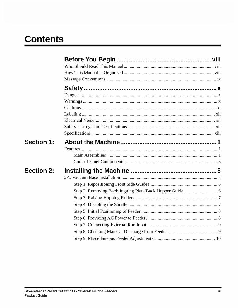
Review the main assemblies in Figure 1-1 to become familiar withnames and locations of feeder parts and adjustments. This will helpprepare you for initial setup. Descriptions are found in Table 1-1.
Review the control panel components in Figure 1-2 to becomefamiliar with names and locations of specific connectors, switches,and controls. This will help prepare you for installation and operation.Descriptions are found in Table 1-2.
AC PowerCord
Figure 1-1. Main Assemblies of the Reliant 2600/2700 Universal Friction Feeder
(2)Hold-Down Spring
Assemblies(Inserter
Applications Only)
• Feeders can be configured three ways:presentation mode only, continuous mode only,or dual mode (both).
• Presentation mode feeders can be used forinserter applications.
• Continuous mode feeders can be used forvacuum, non-vacuum base applications.
• Dual mode feeders can be used for eitherpresentation or continuous mode applications.
• For purposes of illustration, a dual-modefeeder is shown in all drawings of this manual.
NOTE
(2)T-Handle Screws
(InserterApplications Only)
Insert Plate Guide(Inserter
Applications Only)
Side Guides(Adjustable)
Gate Assemblyand Adjustment
Feed Belts
Photo Sensor andFlexible Extension
Table Top
Back Wedge andAdjustments
Control Panel(This Side)
Top Roller Hold-DownAssembly (Adjustable)
Discharge Belts
DischargeSafety Shield
Features
Main Assemblies
Loose Parts Supplied Not Shown:
• Side Guides (2)
• External Run Input Cord (Vacuum BaseApplications Only)
• Support Pedestal (Inserter ApplicationsOnly)

2 Streamfeeder Reliant 2600/2700 Universal Friction FeedersProduct Guide
Feature Description
Gate assembly and adjustment Mounted on a gate bracket assembly above the feed belts, this deviceprovides a curvature to help preshingle stacked material. When properlyadjusted, a clearance is created to help singulate and feed material. (Note:For multiple page material, a 1 to 1.5 maximum thickness is typical.)
Table top Used to support the back wedge.
Side guides (adjustable) Holds a stack of material to be fed and helps keep it straight for properentry through the gate assembly area. Single adjustment knob allows youto move side guides together or apart for different size material. Can bepositioned equally or offset. (Note: Dual-knob design also available.)
Back wedge and adjustment Lifts the material to keep it off the table top, reduces excessive contactwith the feed belts, and helps push the material against the curvature ofthe gate assembly. To achieve proper lift, adjustment wing-nuts andlocking levers allow you to slide the wedge to various positions andangles.
Photo sensor and flexible extension (Note: Inserter applications only.) Also called a sheet-detect photo sensor,it “looks” for the leading edge of the material to stop the feeder. Foroptimum setting, a flexible extension allows you to adjust for distance andperpendicular angle to material.
Feed belts and discharge belts Feed belts: Provides the friction and motion necessary to pull individualmaterial from the bottom of the stack and through the gate assembly area.Discharge belts: Combined with the top roller hold-down assembly,provides the friction and motion necessary to pull material away from thegate assembly area.
Top roller hold-down assy (adjustable) A block of small rollers mounted on a movable shaft. Used to gently forcethe material down on the discharge belts so that it can be controlled after itexits the gate assembly area. To achieve proper downward pressure,T-nuts allow you to loosen the shaft to adjust block up or down.
Control panel All connectors and switches for sensor, interface, and AC power arelocated here. For descriptions, see Figure 1-2 and Table 1-2.
AC power cord, 8 ft. (2.44 m) IEC320 removal three-prong. Shipped loose.
Discharge safety shield Provides residual risk protection to operator when feeder is running.Built-in interlock switch stops the feeder when opened.
Support pedestal (Note: Inserter applications only.) Supports part of feeder that extendsover the inserter’s back deck plate. Includes built-in height adjustment.
Loose Parts
External run input (optional) (Note: Vacuum base and Bryce 16K base applications only.) This two-wireinterface cable allows the feeder to be turned On or Off with the host base.
Hold-down spring assemblies (Note: Inserter applications only.) As a piece of material exits the feedergate assembly area, these two hold-down spring assemblies help keep italigned and in proper position for the gripper jaw. Mounted on inserter.
T-handle screws (Note: Inserter applications only.) These two hand-tightening screwssecure the feeder to the inserter back deck plate. Fastened to undersideof feeder.
Insert plate guide (Note: Inserter applications only.) This plate is supplied with your feederand is to be mounted on the inserter’s back deck plate (if required).
Table 1-1. Main Assemblies Feature Descriptions

Streamfeeder Reliant 2600/2700 Universal Friction Feeders 3Product Guide
Feature Description
AC power cordset connector Cordset plugs into this IEC320 connector to provide feeder with powerfrom a grounded/fused outlet. Switchable for either 115- or 230-VAC.
External run input connector (optional) (Note: Vacuum base only.) This 2-pin connector (labeled External RunInput) is used to carry start/stop signals from a vacuum or non-vacuumbase to the feeder.
Power On/Off Toggles AC power On or Off.
Fuse holder Contains two replaceable 3-Amp, 5-mm time delay fuses. IMPORTANT:Always make sure power module is replaced exactly as removed. Failureto follow this caution can result in damaged electrical parts.
Reset button/fault indicator Labeled Reset, the primary purpose of this pushbutton switch/indicator isto reset the feeder after: 1) a “time-out” occurs or, 2) the discharge safetyshield is opened. "Time-outs" occur: 1) during a misfeed or, 2) when thehopper runs out of material. Built-in indicator illuminates and audible alarmsounds: 1) steady during a time-out condition; 2) flashing light/intermittentalarm during an “open” discharge safety shield.
Mode switch (dual mode only) This slide switch (labeled Continuous/Presentation) allows you to usethe feeder for either inserter applications (using “presentation mode”) orvacuum, non-vacuum base applications (using “continuous mode”). Note:Continuous mode feeders may be configured with a switch that is labeledContinuous/Ext. Run.
Variable speed control This dial switch (labeled Speed) allows the feeder speed to besynchronized with an inserter, vacuum or non-vacuum base. Turningcounterclockwise decreases speed; clockwise increases speed.
Table 1-2. Control Panel Feature Descriptions
Figure 1-2. Control Panel Components
Control Panel Components
Reset Button/Fault Indicator
AC PowerCordsetConnector
Power On/Off
Fuse Holder Mode Switch(Optional)
VariableSpeedControl
ExternalRun InputConnector(Optional)
SPEED– +

4 Streamfeeder Reliant 2600/2700 Universal Friction FeedersProduct Guide
Notes

Streamfeeder Reliant 2600/2700 Universal Friction Feeders 5Product Guide
2 Installing the Machine
!!!When performing initial installation, alwaysmake sure you turn Off the main power switchand disconnect all equipment from theelectrical power source. Failure to do so canexpose you to a potential startup and movingparts which can cause serious injury.
Do not attempt feeder installation while thefeeder and machine of application arerunning. Failure to do so can expose you tomoving parts which can cause serious injury.Do not wear loose clothing when operating thefeeder.
Avoid turning on the feeder or making initialadjustments until all parts are secured. Failureto do so can cause damage to equipment.
This section provides information on how to install the Reliant2600/2700 Universal Friction Feeder in the following applicationenvironments:
• Vacuum base installation (2A)
• Inserter installation (2B)
• Bryce 16K ink jet printer base installation (2C)
Information for a particular application typically includes proceduresfor basic parts removal, feeder mounting and alignment, and cableconnections for power and control interface. Information that relatesto specific adjustments you must make to feeder prior to startup andoperation is found in Section 3, Preparing for Operation.
2A:Vacuum BaseInstallation
Installation of the Reliant 2600/2700 Universal Friction Feeder with“continuous mode” or “dual mode” configurations onto various typesof vacuum and non-vacuum bases is a relatively simple procedure.Several minor modifications to the vacuum base are required prior tomounting, wiring, and aligning the feeder.
To install the feeder onto a vacuum base, perform the following steps:
1: Repositioning front side guides
2: Removing back jogging plate/back hopper guide
3: Raising hopping rollers
4: Disabling the shuttle
5: Initial positioning of feeder
6: Providing AC power to feeder
7: Connecting external run input
8: Checking material discharge from feeder
9: Miscellaneous feeder adjustments

6 Streamfeeder Reliant 2600/2700 Universal Friction FeedersProduct Guide
1. Loosen locking knobs at both side guides (Figure 2-1).
2. Slide each side guide to the outermost position. Do not lock inplace.
STEP 2:Removing Back JoggingPlate/Back Hopper Guide
STEP 1:Repositioning FrontSide Guides
Figure 2-1. Front Side Guides Being Repositioned
1. Loosen each of the setscrews at the two shaft housingassemblies A and B (Figure 2-2).
2. Slide shaft end closest to the vacuum base gate out of housingA (with jogging plate/hopper guides still attached). Slideshaft back far enough on housing B to allow removal ofjogging plate/hopper guides.
3. Loosen locking knob and slide jogging plate/back hopperguide off of shaft and away from the surface of the vacuumbase.
4. Return shaft end to housing B. Lock setscrews in both housingassemblies.
Figure 2-2. Back Jogging Plate/Back Hopper Guide Removal
Front sideguides
Lockingknob
A
BLocking knob

Streamfeeder Reliant 2600/2700 Universal Friction Feeders 7Product Guide
1. Locate the gate adjustment knobs (Figure 2-3) and turncompletely in a clockwise direction to raise hopping rollers.
2. Locate the vertical adjustment lever on the hopping rollersassembly and push down all the way. This will raise the feedrollers to highest vertical position possible, making formaximum clearance.
STEP 3:Raising Hopping Rollers
If additional control of material is requiredduring feeding, you may choose to keep thebase’s hopping roller assembly in the down (ornormal) position.
NOTE
1. Remove side access panel from vacuum base enclosure.
2. Locate the reciprocating arm and reciprocating block directlybeneath the underside of shuttle (Figure 2-4).
3. Using a box wrench, remove the hex-head rod end bearingbolt holding the reciprocating arm to the reciprocating block.
4. Once the bearing bolt is removed, the reciprocating arm iseffectively disconnected. As the shaft is connected to theshuttle base plate on the other end, simply allow the shaft tohang in-position, with no further disassembly.
5. Make sure the base plate of shuttle is all the way forward(toward the vacuum base gate).
Figure 2-3. Using the Adjustments to Raise Hopping Rollers
STEP 4:Disabling the Shuttle
To prevent any accidental startup of shuttlemotor and to eliminate the hazard of movingparts, you can prevent accidental startup byeither disconnecting vacuum base from ACpower at the outlet, or you can remove theinternal AC power fuse (located behind theaccess door of the vacuum base).
!!
Figure 2-4. Disabling the Shuttle from Inside the Access Panel
Vertical adjustmentlever
Gate adjustmentknob
Reciprocatingarm
Hex-headrod end
bearing boltReciprocating
block
8 Streamfeeder Reliant 2600/2700 Universal Friction FeedersProduct Guide
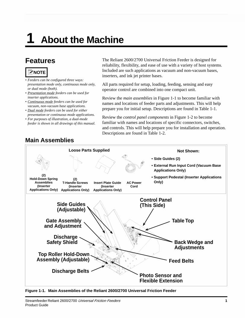
1. Lift the feeder onto the top plate of the vacuum base and slideforward toward the vacuum base gate.
2. Center the feeder between the two side guides as you positionthe feeder fully forward. To verify centering, sight down thecenter of the feeder gate, making sure it is in-line with thevacuum base gate (Figure 2-5).
3. Trap the feeder in-between the vacuum base side guides bysliding each in toward the side plates of the feeder until theygently touch. Tighten side guide knobs to secure in position.
STEP 5:Initial Positioningof Feeder
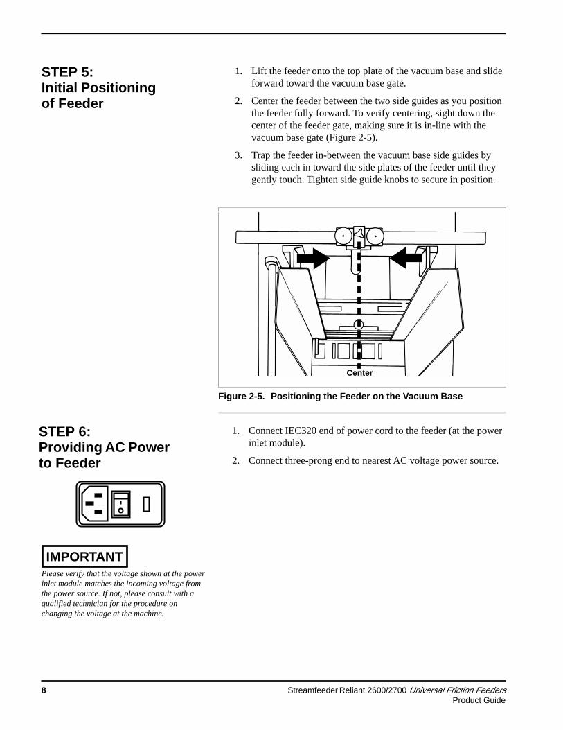
1. Connect IEC320 end of power cord to the feeder (at the powerinlet module).
2. Connect three-prong end to nearest AC voltage power source.
Figure 2-5. Positioning the Feeder on the Vacuum Base
STEP 6:Providing AC Powerto Feeder
Please verify that the voltage shown at the powerinlet module matches the incoming voltage fromthe power source. If not, please consult with aqualified technician for the procedure onchanging the voltage at the machine.
Center
IMPORTANT

Streamfeeder Reliant 2600/2700 Universal Friction Feeders 9Product Guide
Using the two-wire interface cable supplied for vacuum baseapplications:
1. At the feeder, connect external run input cable to feeder usingthe two-pin threaded connector on the control panel.
2. At the vacuum base, open access door at end of the lowerenclosure to locate start/stop control circuit (Figure 2-6).
3. Route internal run input cable from the feeder to this area.
4. Determine the exact run input voltage required by checkingthe label on the run input cable.
5. Interface the two bare wire leads at the opposite end of theinterface cable to the vacuum base start/stop circuit. Thisinvolves splicing the black (GND) wire and red (AC, DC ordry contact) wire to the start/stop circuit.
STEP 7:ConnectingExternal Run Input
This procedure should be performed only by aqualified technician.
IMPORTANT
As material leaves the feeder gate cylinder, the trailing edge must beunder the hold-down block as the leading edge is entering the vacuumbase transfer section. In otherwords, there must be a good transfer ofmaterial from the feeder hold-down block to the vacuum base transfersection.
To verify:
1. Slide feeder back far enough to clear the vacuum base sideguides. If necessary, loosen the knobs on both side guides andpull to the outside slightly to allow movement of the feeder.
2. Insert a piece of material under the hold-down block/ballbearings in such a way that approximately 2/3 of the leadingedge is extending out beyond the feeder (Figure 2-7).
3. Slide feeder back into position, making sure it is againcentered between the side guides. As you do so, also makesure that the leading edge of the material moves into thetransfer section of the vacuum base unobstructed.
Figure 2-6. Gaining Access to Vacuum Base Start/Stop Circuit
STEP 8:Checking MaterialDischarge from Feeder
Make sure rollers on vacuum base are raised inthe highest vertical position so that it does notinterfere with the material.
IMPORTANT
Access door

10 Streamfeeder Reliant 2600/2700 Universal Friction FeedersProduct Guide
Figure 2-7. Checking for Proper Material Discharge from Feederto Vacuum Base
4. Check to make sure the material is still under the hold-downblock/ball bearings and also resting on the vacuum basetransfer section.
5. Trap the feeder in-between the side guides until they gentlytouch. Tighten side guide knobs.
1. Make sure the feeder mode switch is set to “continuous”(Figure 2-8A). This will disable the photo sensor on dual-mode models. Set to "external" run on continuous-modemodels.
2. Set the variable speed control (Figure 2-8B) to the lowestspeed (counterclockwise). Gradually increase the speed tomatch the speed of the vacuum base, thus bringing the gap ofthe material closer together.
STEP 9:MiscellaneousFeeder Adjustments
Figure 2-8. Location of Mode Switch and Variable Speed Control
Continuous
Presentation
A B
STEP 8:Checking MaterialDischarge from Feeder(continued)
- +SPEED
If you change modes while feeder power is On,the current mode selection will not be applieduntil you turn power Off and then On again.
IMPORTANT
Leading edgeshould be 2/3 intotransfer section

Streamfeeder Reliant 2600/2700 Universal Friction Feeders 11Product Guide
Installation of the Reliant 2600/2700 Universal Friction Feeder ontothe back deck plate of an inserter is a relatively simple procedure.Several minor modifications to the selected insert station are requiredprior to mounting, wiring, and aligning the feeder.
To install the feeder, perform the following steps:
1: Removing rear guide assembly
2: Removing T-plate
3: Repositioning separator foot
4: Removing suction cup and closing off vacuum hose
5: Repositioning insert guide tabs
A: Optional step – Installing insert plate guide
6: Installing feeder hold-down spring assemblies
7: Aligning feeder with insert station
8: Securing feeder to inserter
9: Installing support pedestal
10: Providing AC power to feeder
11: Initial feeder photo sensor positioning
STEP 1:Removing RearGuide Assembly
At the selected insert station, remove the fasteners that hold theinserter rear guide assembly to the inserter back deck plate. Lift rearguide assembly off of back deck plate (Figure 2-9).
Figure 2-9. Removing Guide Assembly Rear from Inserter
Rear guideassembly
2B:Inserter Installation

12 Streamfeeder Reliant 2600/2700 Universal Friction FeedersProduct Guide
STEP 2:Removing T-Plate
With the rear guide assembly removed, you can now access theinserter T-plate. Simply lift off of back deck plate (Figure 2-10).
Figure 2-10. Removing T-Plate from Inserter
T-plate
STEP 3:RepositioningSeparator Foot
1. Locate the separator foot at the front side of the inserterstation.
2. With a screwdriver, loosen the inserter separator foot and tiltaway slightly from insert station assembly (opposite feeder)so that foot does not interfere with material being fed (Figure2-11).
3. Retighten to secure.
Figure 2-11. Repositioning Separator Foot at Front of Inserter
Separator foot

Streamfeeder Reliant 2600/2700 Universal Friction Feeders 13Product Guide
STEP 4:Removing Suction Cupand Closing Off VacuumHose
1. Locate the suction cup and hose from front side of insertstation.
2. Remove suction cup from vacuum assembly (Figure 2-12).
3. Lower and tilt the adjustable vacuum assembly forward (byturning the built-in thumbscrew). The vacuum assembly maybe moved down and to one side if it interferes with thematerial being fed.
4. Close off the vacuum hose opening; any convenient pluggingmethod will do.
Figure 2-12. Removing Suction Cup from Vacuum Assembly
Suction cup
Vacuum assembly

14 Streamfeeder Reliant 2600/2700 Universal Friction FeedersProduct Guide
STEP 5:RepositioningInsert Guide Tabs
1. Cycle the inserter until the gripper arm jaw is approximately.5 in. (12.7 mm) from the hopper plate (leading edge ofmaterial exiting feeder stops here).
2. Locate the two insert guide tabs that protrude from under theback deck plate. Bend these tabs as required (either up ordown) until their top surface is slightly above the bottom ofthe gripper arm jaw (Figure 2-13A). The material to be runwill rest on these tabs. The bottom of the gripper arm jawmust pass under the material without making contact with it.
3. As it is important that there be adequate clearance between theguide tabs surface and the gripper jaw, use a flat, thin rule (orgauge) to test for clearance (Figure 2-13B). Ideally, thegripper jaw should be fully open when testing.
4. Center the gauge on the guide tabs and slide the gauge backand forth on the tabs, making sure the gripper jaw does nottouch the bottom of the gauge (Figure 2-13B).
Figure 2-13. Repositioning Guide Tabs and Testing forClearance
Mailcrafters' inserters only:Remove the two insert guide tabs that protrudefrom the back deck plate. Make a bend in eachtab approximately 1.375 in. (34.9 mm) from thetip by placing the tab approximately 1.375 in.(34.9 mm) into the rear guide assembly. Bend thetab slightly and repeat same for second tab.Reinstall insert guide tabs to back deck plate.
NOTE
Ruler orgauge
A B

Streamfeeder Reliant 2600/2700 Universal Friction Feeders 15Product Guide
5A: Optional Step —Installing Insert PlateGuide
When feeding materials less than 5 in. (12.7 cm) wide, you mustinstall the provided insert plate guide with your machine. Install itfrom the underside of the back deck plate using the two provided hex-head screws; reuse the two slots previously used for mounting the rearguide assembly.
To install:
1. Start the screws from the top side of the back deck plate,leaving them loose so you can move the insert plate guideduring placement (Figure 2-14A).
2. Position the insert plate guide so that the top surface is slightlyabove the bottom of the gripper arm jaw.
3. Tighten to secure.
4. As it is important that there be adequate clearance between theguide tabs surface and the gripper jaw, use a flat, thin rule (orgauge) to test for clearance (Figure 2-14B). Ideally, thegripper jaw should be fully open when testing.
5. Center the gauge on the guide tabs and slide the gauge backand forth on the tabs, making sure the gripper jaw does nottouch the bottom of the gauge (Figure 2-14B).
Figure 2-14. Installing Optional Insert Plate Guide andChecking for Clearance
Insert plateguide
Allenwrench
Ruler orgauge
A B

16 Streamfeeder Reliant 2600/2700 Universal Friction FeedersProduct Guide
1. Using the two provided hold-down spring assemblies (withsupport bars), place each on the insert station rail (feeder sideof inserter).
2. Position each spring support bar so they are equally spacedfrom each edge of the material to be run (Figure 2-15A).
3. Tighten the built-in wing nut on each to secure.
4. Check for placement and pressure of the hold-down springassemblies by sliding a piece of material to be run under thesprings (Figure 2-15B). There should be a “slight drag” whenmoving the material back and forth.
5. Make adjustments as required and recheck.
STEP 6:Installing FeederHold-Down SpringAssemblies
NOTE
Figure 2-15. Installing Hold-Down Spring Assemblies andTesting for Drag
Feederhold-downspring
Feederhold-downsprings
Knowing how far from each edge of the materialto place the hold-down spring assemblies is acombination of intuition and testing.
TIP
With material inserted between the springs andthe insert guide tabs, test the spring tension bysliding the material back and forth. Tensionshould not be so great that it distorts the materialas it moves.
If adjustment is required, loosen the hex-headscrew for each spring and move up or down onsupport bar. Retighten when optimum tension isachieved.
TIP
Certain inserter models require hold-down springassemblies to mount from the bottom side of thecrossbar (see figure below). To invert, simplyremove screw and invert L-bracket and spring.
A B

Streamfeeder Reliant 2600/2700 Universal Friction Feeders 17Product Guide
STEP 7:Aligning Feeder withInsert Station
1. Position the feeder on the rear deck plate so the two slots onthe back deck plate line up with two threaded holes in thebottom of the feeder (Figure 2-16A).
2. Using the two provided T-handle screws, start these part wayinto the bottom threaded holes of the feeder base plate fromthe underside of the back deck plate (but not tight).
3. Make sure a piece of material to be run is placed under thehold-down springs (and centered), with the front edge of thematerial in-line with the front hopper plate.
4. Carefully slide the feeder toward the gripper arm (Figure 2-16B) until the trailing edge of material fits between the feederexit rollers (.25-.5 in. or 6.4-12.7 mm of material).
Figure 2-16. Aligning Feeder with Insert Station
NOTE
If there are brackets or hangers in the way, youmay have to adjust the feeder side-to-side byselecting any of the three hole positions in thebottom mounting plate. See figure below.
A B
Threaded holes
T-handlescrew
STEP 8:Securing Feeder toInserter
When you are satisfied with the alignment, secure the feeder bytightening the two T-handle screws from underside of inserter reardeck plate (Figure 2-17).
TIP
If you need to move the feeder side-to-side tofine-tune the alignment with the insert station,use any of the three hole positions in the bottommounting plate. See figure below.
Threaded holes
T-handlescrew
Figure 2-17. Securing Feeder to Back Deck Plate
18 Streamfeeder Reliant 2600/2700 Universal Friction FeedersProduct Guide
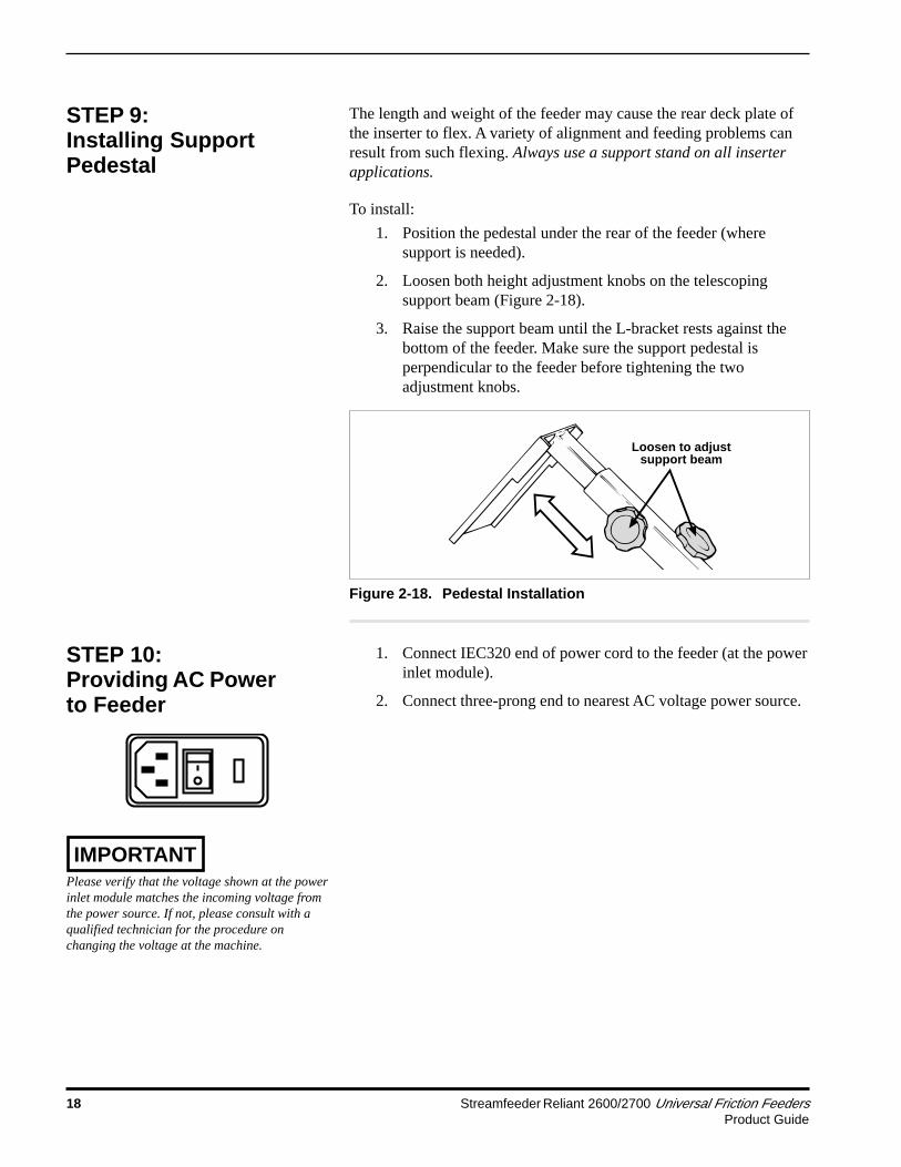
STEP 9:Installing SupportPedestal
The length and weight of the feeder may cause the rear deck plate ofthe inserter to flex. A variety of alignment and feeding problems canresult from such flexing. Always use a support stand on all inserterapplications.
To install:
1. Position the pedestal under the rear of the feeder (wheresupport is needed).
2. Loosen both height adjustment knobs on the telescopingsupport beam (Figure 2-18).
3. Raise the support beam until the L-bracket rests against thebottom of the feeder. Make sure the support pedestal isperpendicular to the feeder before tightening the twoadjustment knobs.
Loosen to adjustsupport beam
Figure 2-18. Pedestal Installation
1. Connect IEC320 end of power cord to the feeder (at the powerinlet module).
2. Connect three-prong end to nearest AC voltage power source.
STEP 10:Providing AC Powerto Feeder
Please verify that the voltage shown at the powerinlet module matches the incoming voltage fromthe power source. If not, please consult with aqualified technician for the procedure onchanging the voltage at the machine.
IMPORTANT

Streamfeeder Reliant 2600/2700 Universal Friction Feeders 19Product Guide
STEP 11:Initial Feeder PhotoSensor Positioning
1. With the machine turned Off, position the photo sensor so it issomewhat centered between the outside edges of the material.
2. Next, adjust the sensor so it points exactly at the leading edgeof material being held by the hold-down springs (Figure 2-19). Use the flexible extension arm to maneuver the photosensor into position for desired height and angle.
3. During the final adjustment of the photo sensor, you need toactually load material into hopper, turn the feeder Off, andcycle the inserter. See Section 3, Preparing for Operation, formore information.
NOTE
The final photo sensor adjustment will alignslightly to the rear of the leading edge. This isbecause when the photo sensor signals the feederto stop, the motor will over-travel slightly.
Figure 2-19. Initial Photo Sensor Adjustment
A perpendicular alignment to the material ispreferred. However, in many instances you maybe limited to an angular alignment due to theconstraints of the flexible extension arm.
IMPORTANTPhotosensor

20 Streamfeeder Reliant 2600/2700 Universal Friction FeedersProduct Guide
2C:Bryce 16K Ink JetPrinter BaseInstallation
Interfacing the Reliant 2600/2700 Universal Friction Feeder to theBryce 16K ink jet printer base is a relatively simple procedure. Nomodifications to the Bryce 16K base are required prior to mounting,wiring, and aligning the feeder.
To install the feeder, perform the following steps:
1: Position the feeder and the Bryce 16K base
2: Wire the feeder to the Bryce 16K base
3: Provide AC Power to Feeder
STEP 1:Positioning the Feederand the Bryce 16K Base
Using the optional roll-up stand provided for Bryce 16K baseapplications:
1. Position the feeder (and stand) at the “upstream” end of theconveyor.
2. Adjust the feeder stand so that outermost discharge roller offeeder is at the same height as the top of the Bryce 16K baseconveyor belt.
3. Allow for a horizontal distance from .25 in. (6.35 mm) to .50in. (12.7 mm) between the feeder discharge roller and theBryce 16K base conveyor belt.
Using the two-wire interface cable supplied for Bryce 16K baseapplications:
1. At the feeder, connect external run input cable to feeder usingthe two-pin threaded connector located on the control panel.
2. At the Bryce 16K base, remove panel to access the maincontrol circuit board.
3. Splice the black (GND) wire and red (+24 V) wire on theopposite end of the interface cable into the GND and +24 Vwires connecting the Bryce 16K base main circuit board andthe shingling conveyor motor.
Figure 2-20. Wiring the Feeder into the Bryce 16K Base
STEP 2:Wiring the Feederto the Bryce 16K Base
This procedure should be performed only by aqualified technician.
IMPORTANT
Main controlcircuit board
+24 V
GND
To shinglingconveyor motor
Red+24 V
BlackGND
Threadedconnector atfeeder control panel
External Run Input

Streamfeeder Reliant 2600/2700 Universal Friction Feeders 21Product Guide
1. Connect IEC320 end of power cord to the feeder (at the powerinlet module).
2. Connect three-prong end to nearest AC voltage power source.
STEP 3:Providing AC Powerto Feeder
Please verify that the voltage shown at the powerinlet module matches the incoming voltage fromthe power source. If not, please consult with aqualified technician for the procedure onchanging the voltage at the machine.
IMPORTANT

22 Streamfeeder Reliant 2600/2700 Universal Friction FeedersProduct Guide
Notes

Streamfeeder Reliant 2600/2700 Universal Friction Feeders 23Product Guide
3 Preparing for Operation
!!!When performing initial feeder adjustmentsprior to operation, always make sure you turnOff the main power switch and disconnect allequipment from the electrical power source.Failure to do so can expose you to a potentialstartup and moving parts which can causeserious injury.
Do not attempt to make any adjustments whilethe feeder and machine of application arerunning. Failure to do so can expose you tomoving parts which can cause serious injury.Do not wear loose clothing when operating thefeeder.
Avoid making adjustments with loose orunsecured parts. This can potentially damageparts.
Once the Streamfeeder Reliant 2600/2700 Universal Friction Feeder isinstalled on your host system, you are then ready to prepare themachine for operation. To do so, you must perform severaladjustments with the material you are going to be feeding. And, youmust do a test run with this material to verify that it is set correctlybefore you begin cycling the feeder with your particular application.You will have to perform this procedure for material that you plan tofeed.
The adjustments you must make (in order) are as follows:1: Gate assembly adjustment
2: Side guides setting
3: Back wedge adjustment
4: Top roller hold-down assembly setting
4A: Optional step – Final photo sensor adjustment forinserter applications only
5: Verifying proper installation

24 Streamfeeder Reliant 2600/2700 Universal Friction FeedersProduct Guide
Figure 3-1. Lifting Gate Assembly Upward to Insert Material
Figure 3-2. Using One Piece of Material toSet Gap
Figure 3-3. Adjusting Gate Assembly for CorrectGap
Pull knob upSlip sheet of
product undergate assembly
Moveproduct
front to back
test forslight drag
Turn knobcounter-
clockwise tolower (ordecrease
gap)
!Excessive lowering of the gate assembly candamage product or lead to premature wear of theO-rings or feed belts.
LOWER
STEP 1:Gate AssemblyAdjustment
If material does not move freely, then the gateassembly is too tight. This can lead to prematurewear of the O-rings or feed belts.
TIP
A wider gap between product and belt providesthe highest tolerance for curled and bent edges.
ProcedureTo adjust the gate assembly for proper gap:
1. Slide a single sheet of test product under the gate assembly.It may be necessary to pull up on the adjustment knob toallow the piece to be inserted.
2. Test the piece for clearance. Grasp the product with two handsand slide it front-to-back under the gate assembly. A properadjustment allows a slight amount of drag on the top of thepiece.
3. Adjust the knob on the gate assembly until the piece has thedesired drag. Turn the knob clockwise to increase clearance orcounterclockwise to decrease clearance.
4. Repeat the drag tests and adjust as needed to achieveacceptable clearance.
Feeding problems will occur with either too muchmaterial in the hopper, or too large a gapbetween the gate assembly and the material.
NOTE

Streamfeeder Reliant 2600/2700 Universal Friction Feeders 25Product Guide
STEP 1:Gate AssemblyAdjustment(continued)
NOTE
When feeding product with varying thicknessthroughout, it may be necessary to turn bothadjustment rollers 1-2 full turnscounterclockwise to compensate for thedifferential thickness. This procedure allows thegate horizon to “float.”
IMPORTANT
The adjustment knob set screws are pre-set at thefactory to lock the knob to the threaded rod. DONOT OVER-TIGHTEN! Over-tightening the setscrews may damage the components.
To adjust the gate for effective material skew control, follow thesesteps:
1. Repeat drag test.
2. Test the piece for uneven side-to-side drag. Grasp with twohands and slide it front-to-back under the gate assembly. Aproper adjustment allows for equal drag on the left and rightsides of the piece of material.
3. To compensate for greater drag on one side of the material,turn the opposite adjustment roller counterclockwise 1/8 turn.Next, turn the other adjustment roller clockwise 1/8 turn.
4. Repeat drag tests and adjust as needed until equal drag isachieved. You may need to repeat this procedure afterobserving the feeder cycling (refer to Section 4, How toOperate).
Figure 3-4. Horizon Adjustment (shown on Advancing O-RingGate)

26 Streamfeeder Reliant 2600/2700 Universal Friction FeedersProduct Guide
Changing FromFactory SetHigh-Tension toLow-Tension
IMPORTANTWhen changing from a low-tension to high-tension setting, you may have to adjust thestack height downward to prevent feedingproblems.
!Excessive lowering of the gate assembly candamage material and/or lead to prematurewear of the O-rings or feed belts.
NOTE
Certain types of single-sheet material mayrequire even more tension than the high-tension setting can provide. To increasetension even further, place a washer betweenthe cylinder and spring.
Washer
CA B
Figure 3-5. Adjusting Gate Assembly for Low-Tension
ProcedureCertain types of material may demand that you change the gateassembly from a high-tension setting to a low-tension setting (forexample, irregular shaped material).
To change the spring from a high to a low tension, follow these steps:1. Remove the gate assembly from gate bracket assembly. To
do so, pull cylinder down with one hand, lift up on knobwith other, and tip at slight angle to remove.
2. Remove the adjustment knob by turning counterclockwise.Then lift the cylinder off of top of spring.
3. Turn the cylinder around so that the cylinder collar facesup. Then place the cylinder on top of the spring.
4. Replace the adjustment knob (make about 8 revolutions ofthe knob before reinstalling gate assembly on gate plate).

Streamfeeder Reliant 2600/2700 Universal Friction Feeders 27Product Guide
The side guides hold the stack of material being fed, and they guidethe material through the feeder in a straight line of movement.
Adjust the side guides so the material stack maintains uniformity fromtop to bottom, with no drifting or binding. Adjustments are madehorizontally.
Make sure the space between the side guides can accommodate thesize of the material being fed. Consider the following as you adjust theguides:• An initial starting point should always be that each guide is of equal
distance from the center point of the machine.
• Each edge of the material should rest equally on the belts, on bothsides of the gate assembly (or equidistant spacing). However, therecan be certain instances where guides do not need to be centereddue to material characteristics. This is called offset spacing.
• Adjust both side guides to be as close as possible to either sides ofthe material, without causing binding, curling of edges, orresistance to movement.
ProcedureSingle-Knob Side Guides. To adjust each side guide for properequidistant horizontal spacing using the single-knob adjustment,follow these steps (Figure 3-6):
1. Place a small stack of material in the hopper.
2. Using the side guides adjustment knob (centrally locatedbetween the two guides), turn in either direction until guidesare located at the recommended distance from the material:.0625 in. (1.6 mm) from each edge, .125 in. (3.1 mm) overall.
3. Visually check both guides for proper spacing from material.
Dual-Knob Side Guides. To adjust each side guide for properequidistant horizontal spacing using the dual-knob adjustment, followthese steps:
1. Place a small stack of material in the hopper.
2. Start by loosening each side guide wing adjuster(counterclockwise). This will allow you to move each sideguide as needed.
3. Grasp the lower part of each guide and slide to therecommended distance from the material: .0625 in. (1.6 mm)from each edge, .125 in. (3.1 mm) overall. Tighten each wingadjuster after you establish proper position for each guide.
4. Visually check both guides for proper spacing from material.
TIP
A good “rule-of-thumb” measurement to use isabout .0625 in. (1.6 mm) between material edgeand side guide (.125 in. or 3.1 mm overall).
NOTE
There are two types of side guide adjustmentsavailable:
1) Single-Knob: Both side guides controlledsimultaneously by a single knob (as shown inFigures 3-6 and 3-7).
2) Dual-Knob: Each side guide controlled by aseparate knob.
STEP 2:Side GuidesSetting

28 Streamfeeder Reliant 2600/2700 Universal Friction FeedersProduct Guide
Figure 3-7. Individual Side Guide Offset
STEP 2:Side Guides Setting(continued)
Figure 3-6. Horizontal Adjustment of Side Guides
Horizontaladjustment(rotate toadjust bothside guides)
Horizontaladjustment(push down toadjust eitherside guide)
Manually adjusteither side guidefor offset
Single-Knob Side Guides. To adjust each side guide for proper offsethorizontal spacing using the single-knob adjustment, follow thesesteps (Figure 3-7):
1. Push down on the side guides spring-loaded adjustment knobto disengage guides from gear mechanism.
2. Grasp whichever side you wish to offset first and move intoposition.
3. Place a small stack of material in the hopper, with edge ofpaper against offset guide.
4. Move the second side guide so that it is located at therecommended distance from the material: .0625 in. (1.6 mm)from each edge, .125 in. (3.1 mm) overall.
5. Lift up on the spring-loaded adjustment knob so that theguides lock into place.
6. Visually check both guides for proper spacing from material.
Dual-Knob Side Guides. To adjust each side guide for proper offsethorizontal spacing using the dual-knob adjustment, follow these steps:
1. Start by loosening each side guide wing adjuster(counterclockwise). This will allow you to move each sideguide as needed.
2. Repeat steps 2-5 above.
3. Tighten each wing adjuster after you establish proper positionfor each guide.
4. Visually check both guides for proper spacing from material.

Streamfeeder Reliant 2600/2700 Universal Friction Feeders 29Product Guide
STEP 3:Back WedgeAdjustment
NOTE
For more information about optional wedges andtheir use with various materials, see Section 7,Additional Wedges.
Keep in mind that the back wedge works withthe gate assembly to provide the proper lift,curvature of the material, and proper belt/material contact to separate and feed one sheet ata time.
NOTE
There are a number of feeding problems whichcan be solved by simply adjusting the back wedgeto different positions. Some of these problemsinclude double feeds, skewing, twisting, poorsingulation, ink or varnish buildup on the belts,and jamming at the gate assembly area.
TIP
Moving the back wedge too far forward to thegate assembly can create a pinch point betweenthe wedge and the material. If moving the backwedge in is not effective, then an optional wedgemay be required. See Section 7, AdditionalWedges, for more information.
NOTE
ProcedureTo adjust the back wedge for initial proper positioning, follow thesesteps:
1. Grasp a handful of material, approximately 2 to 2.5 in. (5 to 6cm) thick, and preshingle the edges with your thumb(Figure 3-8).
2. Place the preshingled material in the hopper so the edges restagainst the curvature of the gate assembly (Figure 3-9).
3. Turn the back wedge wing-nut adjustment counterclockwiseto loosen the wedge (Figure 3-9).
Figure 3-8. Preshingling a Small Stack of Material By Hand
Figure 3-9. Positioning Material Prior to Loosening Back Wedge
2 to 2.5 in.(5 to 6 mm)
This end againstgate assembly
Back wedgeadjustment
4. Move the back wedge forward and backward until the bottomsheet is not touching the table top (Figure 3-8). A goodstarting point is to measure about .625 in. (16 mm) from thebottom sheet to front edge of table top. Then as you test, youcan “fine-tune” from this point. You can also fine-tune backwedge location by loosening the roller swivel wing-nut topivot the rollers back and forth (Figure 3-9).

30 Streamfeeder Reliant 2600/2700 Universal Friction FeedersProduct Guide
STEP 3:Back WedgeAdjustment(continued)
Figure 3-12. Adjusting Back Wedge for Parallel Figure 3-13. Evenly Adjusting Individual Wedges
Figure 3-10. Adjusting Back Wedge for Parallel Figure 3-11. Evenly Adjusting Individual Wedges
Loosen lockinglever to swivelforward orbackward
Backwedgeparallelto stack
Equaldistance
5. Make sure the edge of the back wedge assembly is parallelwith the edge of the material stack (Figure 3-12). Adjust asrequired and then tighten wing-nut.
6. Check that individual rollers are evenly spaced to provideenough support to lift the material off the table top and feedbelts, without any bowing or twisting (Figure 3-13). Referback to page 28 for guidelines on adjusting individual rollersfor thinner material.
Start withabout .625 in.(16 mm) lift

Streamfeeder Reliant 2600/2700 Universal Friction Feeders 31Product Guide
STEP 4:Top Roller Hold-Down AssemblySetting
The top roller hold-down assembly consists of an array of ballbearings in a block that is mounted on a movable shaft just above thedischarge belt. This assembly rests on top of the material as it exits thegate assembly area. Incorrect hold-down pressure can damagematerial.
Adjust the top roller hold-down assembly for proper amount ofpressure so the material exits the discharge area efficiently andsquarely.
ProcedureTo adjust the top roller hold-down assembly for proper pressure,follow these steps:
1. Loosen the two T-nuts on either side of the shaft (Figure3-14A).
2. Lift up on the top roller hold-down assembly and insert onepiece of material to be fed under the rollers (Figure 3-14B).Then allow the assembly to lightly rest on top of the material.
3. Retighten (or lock) the two T-nuts to secure the top rollerhold-down assembly in position. The proper pressure (or gap)should be retained.
4. Verify that assembly is set for proper amount of pressure (ordrag) by sliding the material back and forth. There should be avery slight amount of drag.
If the roller farthest from the gate assembly istighter than the roller closest to the gateassembly, jamming may occur.
If either adjustment is too tight, material damagemay occur.
IMPORTANT
Figure 3-14. Adjusting Top Roller Hold-Down Assembly
A B
Slip materialunder top rollerhold-downassembly
Loosen T-nutsboth sides

32 Streamfeeder Reliant 2600/2700 Universal Friction FeedersProduct Guide
The photo sensor is mounted on the flexible extension arm to detectthe leading edge of a piece of material to be staged. When the gripperjaw pulls the material from the feeder, the photo sensor no longer“sees” the material and sends a signal to start the feeder. The feederthen moves another piece of material into place, and then stops.
For the photo sensor to be effective, it must be adjusted so each timethe feeder starts, the leading edge of the material being fed stopsin-line with the front hopper plate. The feeder should stop so thetrailing edge of the material has minimal overlap with the next trailingedge exiting the gate assembly area.
ProcedureTo adjust the photo sensor for proper positioning, follow these steps:
1. Prepare your adjustment by loading the hopper withapproximately 2 to 2.5 in. (5 to 6 cm) of material. Make sureyou preshingle the stack so that material rests against thecurvature of the gate assembly.
2. Use your finger or thumb on the drive belt or one of the feedrollers to manually move the bottom sheet of material throughthe gate assembly area and under hold-down springs.Continue until material leading edge is in-line with fronthopper plate, then stop (Figure 3-15).
3. Turn the feeder power On by pushing the horizontal line (—)at the Power On/Off rocker switch.
4A: Optional Step —Final Photo SensorAdjustment (InserterApplications Only)
Standard photo sensor shipped from the factory isa diffuse reflective detector. No adjustment forgain is required or necessary.
NOTE
!Only adjust the photo sensor when the feederpower is Off. Do not attempt to adjust the photosensor while the feeder power is On or while thefeeder is running. Doing so will expose you topinch points which can cause injury to hands orfingers.
Potential damage to feeder parts is avoided ifadjustments are made when the feeder power isOff.
IMPORTANTObserve the overlap between the trailing edge ofthe bottom sheet and leading edge of the nextsheet. It should be approximately .25 in. (6.4 mm)to .5 in. (12.7 mm). If not, refer back to Section 2,2B: Inserter Installation, Step 7, Aligning Feederwith Insert Station, for more information.
Figure 3-15. Moving the First Sheet Into Position
!
Leading edgerests againstfront hopperplate

Streamfeeder Reliant 2600/2700 Universal Friction Feeders 33Product Guide
If the photo sensor is set too far from the surfaceof the material, the feeder will "stream" outproduct and feeder will go into "time-out." Thisindicates the sensor is out of range and thereforewill not “see” the target.
NOTE
On the feeder, such objects as shafts, guides,belts, and supports may cause false “reads” if thephoto sensor is not adjusted properly for thematerial (or target). The resulting problem can beintermittent or continuous feeding. See Section 5,Operational Troubleshooting, for a solution.
IMPORTANT
Figure 3-16 . Optimum Alignment of Photo Sensor
IMPORTANTBlack opaque objects may require a special photosensor. If the photo sensor fails to stop the feederwhen the material is within the target range,consult with a qualified technician.
4A: Optional Step —Final Photo SensorAdjustment (InserterApplications Only)(continued)
Sensing range from the lens to the paper shouldnot exceed 2 in. (5.08 cm).
IMPORTANT
Bottomsheet
Topsheet
Slight overlapat mid-point
4. Simulate gripper jaw action by manually grasping the leadingedge of the bottom sheet and pulling completely away fromthe gate assembly area. Once a piece is removed from thegripper jaw, the sensor sends a signal to the feeder to “stage”the next piece. The leading edge of the “staged” piece shouldbe in-line with the front hopper plate.
5. After running several sheets through, turn the feeder powerOff by pushing the circle (O) at the Power On/Off rockerswitch. Adjust the photo sensor as needed to achieve thecorrect stopping point. An optimum setting is to aim the sensorslightly to the rear of the leading edge (Figure 3-16). Thiscompensates for the slight over-travel of the motor after itturns Off, thus allowing the leading edge to stop in-line withthe front hopper plate.
6. Retest the feeder as needed until optimum results areachieved.

34 Streamfeeder Reliant 2600/2700 Universal Friction FeedersProduct Guide
STEP 5:Verifying ProperInstallation
Before you move on to Section 4, How to Operate, verify that theinstallation is properly done by reading the following to prevent anyoperational problems:
• Review of installation
• Manual test to verify
Review of InstallationPlease notice the three applications covered in the text to follow:vacuum base, inserter, and Bryce 16K base.
Vacuum Base ApplicationsFor the vacuum base installation, it is recommended that you checkthe following to ensure a proper installation:
1. Review all vacuum base preparations to make sure they havebeen properly done.
2. Check interface connection.
3. Check electrical connection.
4. Make sure feeder is properly positioned (or centered).
Inserter ApplicationsFor the inserter installation, it is recommended that you check thefollowing to ensure a proper installation:
1. Review all inserter preparations to make sure they have beenproperly done.
2. Check alignment of feeder with station.
3. Check electrical connection.
4. Make sure feeder is properly secured to the deck plate.
Bryce 16K Base ApplicationsFor the Bryce 16K base installation, it is recommended that you checkthe following to ensure a proper installation:
1. Make sure feeder is positioned close enough to the conveyorso as to allow a smooth transition of material from the feederto the conveyor.
2. Check to make sure feeder is properly aligned horizontallyand vertically with conveyor. Re-adjust if necessary.

Streamfeeder Reliant 2600/2700 Universal Friction Feeders 35Product Guide
STEP 5:Verifying ProperInstallation(continued)
Now that you have made all the necessary adjustments for operation,it is recommended you verify material singulation and separation atthe feeder for your particular application. Before you power-up andrun your machine with a full hopper, manually feed several sheets ofmaterial through the gate assembly area.
Manual Test to Verify (for All Applications)Prepare your test by loading the hopper with approximately 2 to 2.5in. (5 to 6 cm) of material. Make sure you preshingle the stack so thatmaterial rests against the curvature of the gate assembly.
1. Manually feed several sheets of material slowly through thegate assembly area. Move the drive belts by pressing yourthumb against the discharge belt.
2. Observe how individual material enters and exits the gateassembly area. Remember, a properly set gap will allow eachnew sheet to enter at about the center line of the cylinderwhile the bottom sheet is exiting the gate assembly area(Figure 3-17). Ideally, this means a slight overlap of both thefirst sheet and the second sheet (.125 in., or 3 mm) at the gateassembly area. The overlap occurs as the bottom sheet isexiting, and the next sheet is entering.
3. If feeding doubles, move the wedge in towards the gateassembly. Test again.
4. If sheets are overlapping excessively or, if the machine isfeeding doubles, reduce the gap slightly by moving the knobabout 1/8 turn counterclockwise. Test again.
5. As material moves through the hold-down area, check for anyskewing or jamming. Also check for damage to the material.
6. If this or other feeding problems still persist (slipping,skewing, jamming), review all the adjustment procedures inSection 3, Preparing for Operation.
If the gate assembly is too tight, the feeder willhave difficulty pulling the material through thegate assembly area. This will cause “missed”feeds.
NOTE
Figure 3-17. Optimum Overlap and Separation of Material
NOTE
Moving the back wedge too far forward to thegate assembly can create a pinch point betweenthe wedge and the material. If moving the backwedge in is not effective, then an optional wedgemay be required. See Section 7, AdditionalWedges, for more information.
TIP
For certain types of materials, you may have toposition the material “off-center” to prevent anyskewing effect.
Bottomsheet
Topsheet
Slight overlapat mid-point

36 Streamfeeder Reliant 2600/2700 Universal Friction FeedersProduct Guide
Notes

Streamfeeder Reliant 2600/2700 Universal Friction Feeders 37Product Guide
4 How to Operate
Sequence ofOperation
Successful power-up and operation is assured if you apply thefollowing sequence of steps:
1: Loading material in the hopper
2: Determining stack height
3: Powering On feeder
4: Setting/adjusting speed (inserter applications only)
5: Running test cycles
6: Final check
STEP 1:Loading Materialin the Hopper
Preshingling prevents multiple sheets fromjamming under the gate assembly at startup.
NOTE
1. Start by preshingling by hand a small stack of material (Figure4-1) so that it conforms to the curvature of the gate assembly.Push in gently to make sure lead edges touch the gate bracketassembly and front edges of the hopper guides (Figure 4-2).
2. At the back wedge, notice how it helps lift the trailing edgesof the material off the table top and feed belts. Also noticehow the lifting helps to push the preshingled edges against thecurvature of the gate assembly (Figure 4-2).
Figure 4-2. Leading Edges Against Gate BracketAssembly and Side Guides
This endagainst
gate assembly
NOTE
If you wish, loading of material can beaccomplished from the front side of the inserter.
Trailingedges lifted
Edges should beagainst curvature
Figure 4-1. Preshingling of First Stack
This section provides a sequence of operation for the Reliant 2600/2700 Universal Friction Feeder. It also provides information forclearing a jam and for shutdown.

38 Streamfeeder Reliant 2600/2700 Universal Friction FeedersProduct Guide
Power-Up and Test Section 3
STEP 2:Determining Stack Height
1. Gradually add more material to the hopper after the initialstack is formed around the gate assembly. As stack height willhave a preferred minimum and maximum, you will have toexperiment to determine effective range of height (Figure4-3).
2. Make sure the material is loaded in the hopper as straight aspossible. Before adding to hopper, “jog” each hand-full ofmaterial on a flat surface to make sure lead edges are even.As you add each handful, gently push in each stack so thatlead edges rest firmly against front of side guides.
Turn the feeder power On by pushing the horizontal line (—) at thePower On/Off rocker switch.
• For vacuum base and Bryce 16K base applications only(continuous mode): Feeder motor will not run until theentire base power switch is turned On (feeder On/Off iscontrolled via external run input cable).
• For inserter applications only (presentation mode): As thephoto sensor “sees” the leading edge, the feeder motorshould turn Off. Check the leading edge of bottom sheet. Itshould be in-line with the front hopper plate and ready forcycling.
STEP 3:Powering On Feeder
Figure 4-3. Adding More Material to Hopper
TIP
Stack height affects the downward pressure on thefeed belts. Greater downward pressure canincrease the chances for double feeds.
Add more product:gently push in
to make sure edgestouch back plate

Streamfeeder Reliant 2600/2700 Universal Friction Feeders 39Product Guide
Section 4 Troubleshooting
STEP 5:Running Test Cycles
For vacuum base applications:
1. With the feeder already fully loaded and powered On, run thevacuum base through several cycles.
2. Notice transition of material from feeder gate assembly area tothe transfer area of the vacuum base. Adjust feederhorizontally as needed (refer back to Section 2, Installing theMachine).
3. Adjust feeder speed as needed to coincide with transport beltspeed.
For inserter applications:
1. Jog the inserter to see if hold-down spring pressure is equal.Any unequal spring pressure will skew material in the jaw.
2. With the feeder already fully loaded and powered On, run theinserter through several cycles.
3. Check material alignment to make sure it is consistent withthe grip position (refer back to Section 2, Installing theMachine).
For Bryce 16K base applications:
1. With the feeder already fully loaded and powered On, runseveral pieces through the Bryce 16K system.
2. Notice transition of material from feeder gate assembly area tothe transfer area of the Bryce 16K base. Adjust feedervertically and horizontally as needed (refer back to Section 2,Installing the Machine).
3. Adjust feeder speed as needed to coincide with transport beltspeed.
It might be helpful to know that a properly setgap will allow the leading edge of a sheet to enterat about the center line of the cylinder (refer backto Figure 3-17) as the previous or bottom sheet isexiting the gate assembly area.
TIP
STEP 4:Setting/Adjusting Speed
Note: The following applies to all applications, including both“presentation mode” and “continuous mode.”
1. Set the variable speed control to the lowest speed(counterclockwise).
2. Start by slowly turning the control clockwise to graduallyincrease feeder speed to coincide with the production linespeed of your particular application.
- +SPEED

40 Streamfeeder Reliant 2600/2700 Universal Friction FeedersProduct Guide
STEP 6:Final Check
Make sure:• Leading edge of bottom sheet stops at proper location.
• Proper separation is occurring at gate assembly area.
• Effective preshingling is occurring at curvature of gate assembly.
• Material is not being damaged during cycling.
• Feeder is secured and will not move during operation.
If a jam occurs during operation, follow these steps:
1. Open the discharge safety shield (interlock switch preventsfeeder from starting while shield is in the “open” position).
2. Remove jammed product from feeder. While doing so, try todetermine the cause of the jam (see Section 5, OperationalTroubleshooting).
3. Verify whether any adjustments are loose. If so, refer back toSection 3, Preparing for Operation, for proper adjustmentprocedures.
4. Close the discharge safety shield and reset the feeder bypressing the reset/fault indicator button (labeled Reset).
Should you not be using the feeder for long periods of time, followthese steps to ensure safe and secure storage:
1. Turn the feeder power Off by pushing the circle (O) at therocker Power On/Off rocker switch.
2. Disconnect the feeder power cord from the AC power source.If using the feeder for “continuous mode” applications,disconnect external run input from feeder control panel.
3. Cover the feeder with a cloth or plastic tarp to prevent dustand debris from accumulating.
Shutdown
Clearing a Jam
For inserter applications only: Reposition photosensor (as required).
NOTE

Streamfeeder Reliant 2600/2700 Universal Friction Feeders 41Product Guide
1. Check that the switch is pressed to "On"(or "__" position).
2. Check and secure power cord at ACoutlet.
3. Check and secure cord at AC power inlet(rear of feeder).
4. Check and secure cable connections.Replace if necessary.
5. Consult with a qualified technician.*
6. Consult with a qualified technician.*7. Consult with a qualified technician.*
1. Review gate assembly adjustment inSection 3, Preparing for Operation.
2. Review back wedge adjustment inSection 3, Preparing for Operation.
3. Rotate O-rings. Or, if applicable, replaceangled edge (see Section 6, Inspectionand Care, for procedure). If wear isexcessive, consult with a qualifiedtechnician.*
4. Check material and source.5. Check material and source.
1. See "Feeding Doubles" above.2. Review photo sensor adjustment in
Section 3, Preparing for Operation.3. Reset the feeder by pressing the On/Off
switch to "Off" (or "O" position) and thenback to "On" (or "__" position).
1. Reset the feeder by pressing the On/Offswitch to "Off" (or "O" position) and thenback to "On" (or "__" position).
1. Review loading the material in Section 4,How to Operate.
2. Adjust the side guides further apart toallow freedom of movement betweensheets.
1. On/Off switch in "Off" (or "O" position).
2. Power cord loose or not plugged intooutlet (or AC power source).
3. Female end of power cable loose ornot plugged into AC power inlet at rearof feeder.
4. Faulty external run input connection orcable.
5. No voltage is being applied to theexternal run input connection.
6. Faulty safety interlock switch.7. Blown fuse.
1. Gate assembly improperly adjusted(possibly more than one sheetthickness).
2. .Back wedge improperly adjusted.
3. Worn O-rings (or if applicable, anglededge).
4. Material interlocking.5. Static buildup.
1. Possible overlapping.2. Photosensor not adjusted properly;
may be "seeing" background objects.3. Feeder mode was switched from
"continuous" to "presentation" withpower supplied to the feeder.
1. Feed mode was switched from"presentation" to "continuous" withpower supplied to the feeder.
1. Material stack weight is too low whenstack height is down, resulting inreduction of down pressure.
2. Binding in side guides.
No AC power to feeder
Feeding doubles
Continuous feedingwhile in presentationmode
Feeder times out whilein continuous mode;continuous alarmsound
Feed belts areoperating, but materialnot feeding
5 Operational TroubleshootingTable 5-1 is intended to provide you with quick solutions to the more common day-to-day problems you mayencounter. For additional troubleshooting information, contact a qualified technician.
Table 5-1. Quick-Look Troubleshooting
Problem Cause Solution

42 Streamfeeder Reliant 2600/2700 Universal Friction FeedersProduct Guide
3. Slippery feed belts (material buildup).4. Sheet adhesion or interlocking
between the bottom and next sheet.
5. Gate assembly may be down too tight.
6. Too much weight in hopper.
1. Feeder operation was stopped due toa "time-out" fault (i.e., miss, jam, nomaterial in hopper).
1. Discharge safety shield not closedcompletely.
1. Excessive weight in hopper.2. Excessive down pressure on gate
assembly.
3. Off-centered product from center pointof machine.
4. Stack is bearing down on edge of belt.
5. Belt wear.
6. Rollers out of adjustment.
1. Improper adjustment of any of thefollowing areas:a. Gate assembly.b. Back wedge.c. Top roller hold-down assembly.
1. Back wedge not aligned properly.2. Hold-down spring tension either too
loose or too light.
1. Photo sensor "staging" leading edge ofmaterial too far from hopper plate.
2. Gripper jaw adjusted too far from edgeof hopper plate.
1. Photo sensor "staging" leading edge ofmaterial too far past hopper plate.
2. Gripper jaw adjusted too close to edgeof hopper plate.
Feed belts areoperating, but materialnot feeding (continued)
Feed belts notoperating; continuousalarm sound
Feed belts notoperating; intermittentalarm sound
Feed belt(s) not trackingon rollers
Jamming occurs duringoperation
Material skewing
Material too far fromgripper jaw (inserterapplication only)
Material too deep ingripper jaw (inserterapplication only)
3. Consult with a qualified technician.*4. Review loading the material in Section 4,
How to Operate, or review back wedgeadjustment in Section 3, Preparing forOperation.
5. Review gate assembly adjustment inSection 3, Preparing for Operation.
6. Remove material from stack. Test again.
1. Check is reset button/fault indicator isilluminated. Press Reset button.
1. Check if reset button/fault indicator isblinking. Press Reset button.
1. Reduce weight. Test again.2. Rotate clockwise 1/8 turn to increase gap
and manually test. Also, review gateassembly adjustment in Section 3,Preparing for Operation.
3. Review side guides setting in Section 3,Preparing for Operation.
4. Move stack away from belt, even if thiscauses stack to be aligned off center fromcenter line of feeder.
5. Review gate assembly adjustment andback wedge adjustment in Section 3,Preparing for Operation. Also see Section6, Inspection and Care. If wear isexcessive, consult with a qualifiedtechnician.*
6. Consult with a qualified technician.*
a. Turn the Power switch to "Off" by pushingthe circle ("O").
b. Removed jammed material from feeder.While doing so, try to determine the causeof the jam.
c. Verify each adjustment by reviewingSection 3, Preparing for Operation.
1. Review back wedge adjustment in Section3, Preparing for Operation.
2. Review hold-down spring installation inSection 2, Installing the Machine.
1. Review photo sensor adjustment inSection 3, Preparing for Operation.
2. Adjust gripper jaw as required per insertowner's manual.
1. Review photo sensor adjustment inSection 3, Preparing for Operation.
2. Adjust gripper jaw as required per inserterowner's manual.
Table 5-1. Quick-Look Troubleshooting (continued)
Problem Cause Solution

Streamfeeder Reliant 2600/2700 Universal Friction Feeders 43Product Guide
6 Inspection and Care
Please read this Section to learn how to:
• Visually inspect your machine to detect part problems which mayrequire adjustment or replacement.
• Periodically care for your machine to prevent any operationalproblems.
!!!
Visual Inspection
Checking for Timing and Drive Belt WearReferring to Figure 6-2, check for visual signs of:
• Fraying. Replace as required.
• Missing teeth. Replace as required.
• Cracking. Replace as required.
• Paper residue buildup. Clean from belts, especially in grooves.
Checking for Feed and Discharge Belt WearReferring to Figure 6-1, check for visual signs of:
• Walking. Replace as required.
• Cracking. Replace as required.
• Thinning. Replace as required.
Figure 6-2. Inspecting Timing Beltand Drive Belt
Figure 6-1. Inspecting Feed andDischarge Belts
Feed belts
Discharge belts
Drive belt
Timing belt
When performing initial feeder adjustmentsprior to operation, always make sure you turnOff the main power switch and disconnect allequipment from the electrical power source.Failure to do so can expose you to a potentialstartup and moving parts which can causeserious injury.
Do not attempt to make any adjustments whilethe feeder and machine of application arerunning. Failure to do so can expose you tomoving parts which can cause serious injury.Do not wear loose clothing when operating thefeeder.
Avoid making adjustments with loose orunsecured parts. This can potentially damageparts.

44 Streamfeeder Reliant 2600/2700 Universal Friction FeedersProduct Guide
Visual Inspection(continued)
Ensuring Proper Feed and Discharge BeltTrackingReferring to Figure 6-3, check for visual signs of:
• Stretching.
• Improper roller adjustment.
Ensuring Proper Timing and Drive BeltTrackingReferring to Figure 6-4, check for visual signs of:
• Misaligned timing pulleys.
Figure 6-3. Ensuring Proper Feed Belt Tracking
Figure 6-4. Ensuring Proper Drive Belt Tracking
Feed belt drift
Discharge belts
Drive belt drift
Timing belt drift

Streamfeeder Reliant 2600/2700 Universal Friction Feeders 45Product Guide
Visual Inspection(continued)
Checking for Gate Assembly WearCheck for visual signs of wear:
• Advancing O-ring, or Standard O-ring: Flat areas along theO-rings (Figures 6-5 and 6-6, respectively).
• Bar Gate: Angled wedge begins to flatten excessively(Figure 6-7).
Figure 6-6. Standard O-RingGate
Figure 6-7. Bar GateFigure 6-5. AdvancingO-Ring Gate
FlattenedO-rings
Flattened edge(more than 50%)
FlattenedO-rings

46 Streamfeeder Reliant 2600/2700 Universal Friction FeedersProduct Guide
Visual Inspection(continued)
Figure 6-9. Standard O-Ring Gate
Figure 6-10. Bar Gate
Flattenededge rotated
.125 to .25 in.(3 to 6 mm)
Remove angledwedge and replace
Side plate
Cylinder
Advancinglever
Figure 6-8. Advancing O-RingGate
Replacing Worn Angled WedgeTo replace a worn angled wedge (Figure 6-10):
1. Turn Off feeder and remove power cord from outlet.
2. Open discharge safety shield to access gate.
3. Remove gate assembly from gate plate.
4. Remove plate (two screws).
5. Remove angled wedge.
6. Install new angled wedge. Reinstall plate (two screws).
7. Reinstall gate assembly, close discharge safety shield, andrestore power.
Standard O-Ring Gate: Adjusting WornO-RingsTo adjust worn O-rings on standard O-ring gate (Figure 6-9):
1. Turn Off feeder and remove power cord from outlet.
2. Open discharge safety shield to access gate.
3. Remove gate assembly from gate plate.
4. Insert a screwdriver in slot on top of gate assembly and rotatescrewdriver clockwise or counter-clockwise 360° so as tomove worn area of O-ring about .125 to .25 in. (3 to 6 mm).
5. Remove screwdriver and repeat for each ring as necessary.
6. Reinstall gate assembly, close discharge safety shield, andrestore power.
Advancing O-Ring Gate: Adjusting WornO-RingsTo adjust worn O-rings on advancing O-ring gate (Figure 6-8):
1. Turn Off feeder and remove power cord from outlet.
2. Open discharge safety shield to access gate.
3. Make sure advance knob is in-line with the side plate andsecure. Then loosen left and right locking wing nuts.
4. Rotate O-rings by grasping advance knob and pushingtowards gate cylinder about .125 to .25 in. (3 to 6 mm).
5. Retighten locking wing nuts. Then loosen advance knob andmove to original position (in-line with side plate). Retighten.
6. Close discharge safety shield and restore power.

Streamfeeder Reliant 2600/2700 Universal Friction Feeders 47Product Guide
Preventive Care Cleaning Feed and Discharge BeltsTo clean feed belts (Figure 6-11):
1. Turn Off feeder and remove power cord from outlet.
2. Open discharge safety shield.
3. Remove gate assembly from gate plate for easier access tobelts.
4. Apply a small amount of isopropyl alcohol to a soft cloth.
5. Use your hand to move the feed belt, start with one feed beltat a time and carefully press the moistened area of the cloth tothe belt. As you rotate the belt, use moderate pressure to wipeacross the belt, making sure to wipe in direction of grooves.After several rotations of the belt, repeat for each belt.
6. Taking a dry portion of the cloth, go back to the first feed beltcleaned and use moderate pressure against the belt for severalrevolutions to ensure the belt is dried. Repeat for each belt.
7. Reinstall gate assembly, close discharge safety shield, andrestore power.
To clean discharge belts (Figure 6-12):
1. Turn Off feeder and remove power cord from outlet.
2. Open discharge safety shield.
3. To access discharge belts, move top roller hold-downassembly away from discharge belts by loosening two T-nutson either side of shaft. Lift up on top roller assembly.
4. Repeat steps 4-6 above. Repeat for each belt.
5. Reinstall gate assembly, return roller hold-down assembly tooriginal position, close discharge safety shield, and restorepower.
!Use only isopropyl alcohol (98% concentration).Other solvents can cause belts to wearprematurely, and even cause total breakdown ofmaterial.
Cleaning schedule for various materials:
• Typical: every month
• Dusty: after every shift
• High ink or varnish: 1 time per shift
Feed belts
Figure 6-11. Cleaning Feed Belts
Discharge belts
Figure 6-12. Cleaning Discharge Belts

48 Streamfeeder Reliant 2600/2700 Universal Friction FeedersProduct Guide
Preventive Care(continued)
Cleaning schedule for various materials:
• Typical: every month
• Dusty: after every shift
• High ink or varnish: 1 time per shift
Cleaning Gate AssemblyUse only isopropyl alcohol (98% concentration). Do not use anyother types of solvents. They can cause premature wear of thebelts, or even total breakdown of the material.
To clean gate assemblies:
1. Turn Off feeder and remove power cord from outlet.
2. Open discharge safety shield to access gate.
3. Remove gate assembly from gate bracket assembly.
4. Apply a small amount of isopropyl alcohol to a soft cloth.
5. Wipe across O-rings (Figures 6-13 or 6-14), or angled wedgeif applicable (Figure 6-15). First wipe in one direction, thenthe other.
6. Taking a dry portion of the cloth, go back and wipe allsurfaces to ensure they are dried.
7. Reinstall gate assembly, close discharge safety shield, andrestore power. It may be necessary to recheck alignment offeeder with host machine if feeder was moved from originalinstallation position (for a review, refer back to Section 2,Installing the Machine).
Clean all O-Rings Clean angled wedge
Figure 6-13. Advancing O-RingGate
Figure 6-14. Standard O-RingGate
Figure 6-15. Bar Gate
Depending on the application, it may benecessary to move the feeder from originalinstallation so as to access gate assembly.
NOTE
Clean all O-rings

Streamfeeder Reliant 2600/2700 Universal Friction Feeders 49Product Guide
Cleaning Photo Sensor (InserterApplications Only)To clean the photo sensor lens:
1. Turn Off feeder and remove power cord from outlet.
2. Open discharge safety shield to access photo sensor.
3. Using a soft, dry cloth, wipe across the face of the photosensor lens (Figure 6-16).
4. Recheck the adjustments to make sure it is still in alignment tothe target (for a review, refer back to Section 3, Preparing forOperation).
5. Close discharge safety shield and restore power.
Preventive Care(continued)
!Do not use any solvents or cleaning agents whencleaning the photo sensor lens. This can result insurface damage and eventual faulty performance.
Figure 6-16. Cleaning Photo Sensor
Front (Lens)
Side

50 Streamfeeder Reliant 2600/2700 Universal Friction FeedersProduct Guide
Notes

Streamfeeder Reliant 2600/2700 Universal Friction Feeders 51Product Guide
This section provides information about setting up various wedgeswhich are optional with the Reliant 2600/2700 Universal FrictionFeeders.
Now that you are familiar with the basic principles of using a wedge,it is simply a matter of combining these principles with theinformation provided in this Section. This will allow you to getoptimum performance when setting up the wedge included with yourparticular feeder.
The following wedges are covered:
• Load compensating
• Articulating roller
• Extended narrow
• Combination triangle and low-profile
• Separate triangle and low-profile
• Separate articulating roller and low-profile
Load Compensating When to use: Effective for moderately thick material. Due tocharacteristics of material, no mid-range support is required.
Setup guidelines: Adjust so the top angle of wedge preshingles thestack against curvature of gate assembly. Edges of material should notextend beyond the tip of wedge. Ideal separation should be: as thestack moves down the wedge, 3 or 4 sheets of material separate outand come to rest on lower angle of wedge. Then, 3 or 4 sheets ofmaterial fall to table top, which are then replaced with another 3 or 4sheets from stack above (Figure 7-1).
Top
Side
Figure 7-1. Load Compensating Wedge Setup
No mid-rangesupport needed
No product edgepast this point
7 Additional Wedges

52 Streamfeeder Reliant 2600/2700 Universal Friction FeedersProduct Guide
Articulating Roller When to use: Effective for very thick and/or ridged material. Due tocharacteristics of material, no mid-range support is required.
Setup guidelines: Adjust so that roller edges preshingle the stackagainst the curvature of gate assembly. Again, make sure edges ofmaterial do not extend back more than the mid-point of roller(Figure 7-2). Note: With some material that tends to bind together (forexample, perforated material), it may be beneficial to separate 4 to 5sheets of material at the bottom to provide some air space.
Figure 7-2. Articulating Roller Wedge Setup
Extended Narrow
Side
When to use: Effective for moving in close to the gate assembly forsupporting very small material. Due to characteristics of material, nomid-range support is required.
Setup guidelines: Adjust so that wedge preshingles the bottom of stackagainst the curvature of gate assembly. Make sure edges of material donot extend back more than the mid-point of wedge (Figure 7-3).
Side
Top
Figure 7-3. Extended Narrow Wedge Setup
No product edgepast the mid-point
No mid-rangesupport needed
No product edgepast this point
No mid-rangesupport needed
Top
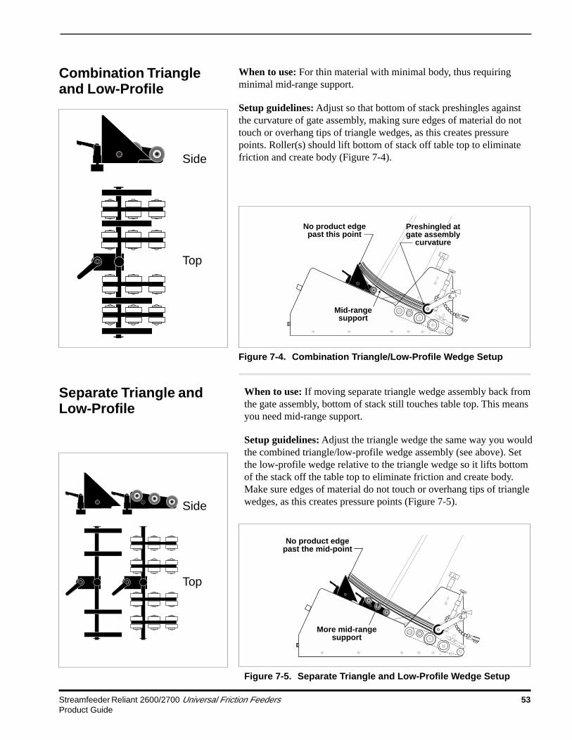
Streamfeeder Reliant 2600/2700 Universal Friction Feeders 53Product Guide
Side
Top
No product edgepast the mid-point
More mid-rangesupport
Separate Triangle andLow-Profile
Figure 7-5. Separate Triangle and Low-Profile Wedge Setup
When to use: If moving separate triangle wedge assembly back fromthe gate assembly, bottom of stack still touches table top. This meansyou need mid-range support.
Setup guidelines: Adjust the triangle wedge the same way you wouldthe combined triangle/low-profile wedge assembly (see above). Setthe low-profile wedge relative to the triangle wedge so it lifts bottomof the stack off the table top to eliminate friction and create body.Make sure edges of material do not touch or overhang tips of trianglewedges, as this creates pressure points (Figure 7-5).
Side
Top
No product edgepast this point
Mid-rangesupport
Preshingled atgate assembly
curvature
Combination Triangleand Low-Profile
When to use: For thin material with minimal body, thus requiringminimal mid-range support.
Setup guidelines: Adjust so that bottom of stack preshingles againstthe curvature of gate assembly, making sure edges of material do nottouch or overhang tips of triangle wedges, as this creates pressurepoints. Roller(s) should lift bottom of stack off table top to eliminatefriction and create body (Figure 7-4).
Figure 7-4. Combination Triangle/Low-Profile Wedge Setup

54 Streamfeeder Reliant 2600/2700 Universal Friction FeedersProduct Guide
Side
Top
No product edgepast the mid-point
More mid-rangesupport
When to use: For thicker material with more body, thus requiringmedium mid-range support. Longer material may also benefit.
Setup guidelines: Initially adjust articulating wedge so that rolleredges preshingle the bottom of the stack against the curvature of gateassembly. Make sure edges of material do not extend back more thanmid-point of rollers (Figure 7-6). Set the low-profile wedge soroller(s) lift bottom of stack off the table top to eliminate friction andcreate body.
Separate ArticulatingRoller and Low-Profile
Figure 7-6. Separate Articulating Roller and Low-ProfileWedge Setup

Streamfeeder Reliant 2600/2700 Universal Friction Feeders 55Product Guide
8 Mechanical Components

56 Streamfeeder Reliant 2600/2700 Universal Friction FeedersProduct Guide
1: TRIANGLE WEDGEASSEMBLY #63311214
NOTE: THIS ASSEMBLY IS STANDARD ONLY ON PRESENTATION MODE FEEDERS
DIAGRAM PART NUMBER QTY DESCRIPTION NUMBER
1-1 1 Wedge Guide Shaft 44633018
1-2 1 SHCS 10-32 X 5/8” LG 00002320
1-3 1 Wedge Block 44633014
1-4 1 T-Nut Round 44633016
1-5 1 Knob 3 Lobe 10-32 X 5/8” LG 44633033
1-6 2 Ring Grip 3/8 Waldes 00001110
1-7 4 Wedge Material Support 43560212
1-8 1 Short Triangle Wedge 63311017 (2) (Ring Grip 3/8 Waldes) (00001110) (2) (Wedge Material Support) (43560212) (1) (Shaft Wedge Guide) (44633017)

Streamfeeder Reliant 2600/2700 Universal Friction Feeders 57Product Guide

58 Streamfeeder Reliant 2600/2700 Universal Friction FeedersProduct Guide
2: SINGLE S WEDGEASSEMBLY #63311026
NOTE: THIS ASSEMBLY IS STANDARD ONLY ON CONTINUOUS & DUAL MODE FEEDERS
DIAGRAM PART NUMBER QTY DESCRIPTION NUMBER
2-1 2 Knob Wing #10 w/o Screw 23500076
2-2 2 SHCS 10-32 X 1” LG 00002335
2-3 1 S Wedge 44633025
2-4 2 Screw Flat Head 10-32 X 1/2” LG 00002330
2-5 2 Spacer .25 X .375 Tapped 10-32 44633027
2-6 2 Screw Socket Set 1/4-20 X 1/4” LG 00002205
2-7 1 Block Mounting 44633026
2-8 1 Shaft Pivot Block 44633028
2-9 2 Adjustment Clamping Handle 1/4-20 X .63 44340015
2-10 2 Bracket Roller Wedge Pivot 43500165
2-11 1 SHCS 10-32 X 5/8” LG 00002320
2-12 1 Shaft Wedge Guide 44633032
2-13 1 Knob 3 Lobe 10-32 X 5/8 44633033
2-14 1 Wedge Block 44633014
2-15 1 T-Nut Round 44633016

Streamfeeder Reliant 2600/2700 Universal Friction Feeders 59Product Guide

60 Streamfeeder Reliant 2600/2700 Universal Friction FeedersProduct Guide
3: 2 KNOB GATE PLATEASSEMBLY #69211011 (2600) OR #67511011 (2700)
NOTE: THIS ASSEMBLY IS STANDARD ONLY ON PRESENTATION MODE FEEDERS
DIAGRAM NUMBER QTY DESCRIPTION P/N 2600 P/N 2700
3-1 2 Lever Adjustment 10-32 X .75 43555098 43555098
3-2 2 Clamp Side Adjust 44675006 44675006
3-3 1 Bar Lower Gate Support 44642022 44675008 2 Hook Gate J 15000007 15000007 2 SHCS 8-32 X 5/8” LG 00002215 00002215
3-4 1 Bar Upper Gate Support 44642021 44675009
3-5 2 Block Side Guide Mount 44675007 44675007
3-6 1 Bar Pre Gate 44642019 44675010
3-7 1 Pre Gate 44642020 44675011 4 Screw Flat Head 10-32 X 1/2” LG SS 00002830 00002830
3-8 1 Block Adjustment Reference 15000003 15000003
3-9 2 SHCS 8-32 X 5/8” LG 00002215 00002215
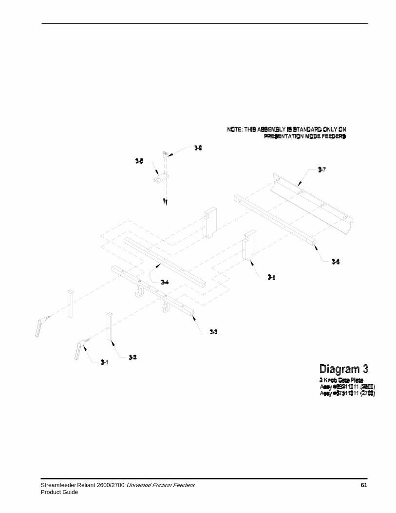
Streamfeeder Reliant 2600/2700 Universal Friction Feeders 61Product Guide

62 Streamfeeder Reliant 2600/2700 Universal Friction FeedersProduct Guide
4: 1 KNOB SOLID GATE PLATEASSEMBLY #69211004 (2600) OR #64011004 (2700)NOTE: THIS ASSEMBLY IS STANDARD ONLY ON CONTINUOUS & DUAL MODE FEEDERS
DIAGRAM NUMBER QTY DESCRIPTION P/N 2600 P/N 2700
4-1 1 Guide Adjustment Cover Side 44692015 44646012 4 BHCS 10-32 X 3/8” LG 00002805 00002805
4-2 1 Gate Support Bar Lower 44692011 44646003 2 Hook Gate J 15000007 15000007 2 SHCS 8-32 X 5/8” LG 00002215 00002215
4-3 2 Rail Side Guide Support 44692013 44646006
4-4 2 Guide Adjustment Block 44646001 44646001 4 Screw Socket Set 1/4-20 X 1/4” 00002205 00002205
4-5 1 Guide Stationary Block Side 44646002 44646002
4-6 4 Rack 44692014 44646010
4-7 2 Spacer Lower 44646015 44646015
4-8 1 Block Adjustment Reference 44646004 44646004 4 BHCS 10-32 X 3/8” LG 00002805 00002805
4-9 1 Shaft Pinion Adjustment 44646005 44646005
4-10 1 Solid Gate Plate 44692012 44640004
4-11 4 Screw Flat Head 10-32 X 3/8” LG 00002234 00002234
4-12 2 Knob Plastic 10-32 w/o Screw 44681021 44681021 2 Screw Socket Set 10-32 X
1 1/2” LG 00003313 00003313 2 Spacer Upper 44646016 44646016
4-13 1 Knob 5 Lobe 44646009 44646009 1 Spring Retainer Upper 44646008 44646008 1 Spring Retainer Lower 44646007 44646007 1 Spring Compression 44646013 44646013
4-14 2 Screw Flat Head 10-32 X 1/2” LG 00002830 00002830

Streamfeeder Reliant 2600/2700 Universal Friction Feeders 63Product Guide

64 Streamfeeder Reliant 2600/2700 Universal Friction FeedersProduct Guide
5: STANDARD O-RING GATEW/HORIZON ADJUST & COVER
ASSEMBLY #69211020 (2600) OR #67511020 (2700)NOTE: THIS ASSEMBLY IS STANDARD ONLY ON PRESENTATION MODE FEEDERS
DIAGRAM PART NUMBER QTY DESCRIPTION NUMBER
5-1 1 Adjustment Knob Assembly for Gate 23511037
5-2 1 Cylinder Gate Spring Tension 23500019
5-3 1 Shaft Gate Lift 23560084 1 Spring Gate Compression 23500083
5-4 1 Mount Gate Lift Shaft 15000001
5-5 1 BHCS 10-32 X 1/2” LG 00002334
5-6 2 Screw 44872005
5-7 12 O Ring Gate Cylinder 23500089
5-8 1 BHCS 10-32 X 1” LG 00002340 1 Washer Flat #10 00002607
5-9 1 Gate Cylinder w/Horizon (Not Sold Separately) 51101001 2 Screw Socket Set 10-32 X 1/4” LG Cup Pt 00002216
5-10 2 Roller 44872003 2 Screw Socket Set 10-32 X 3/8” LG Nylon Tip 44872007
5-11 2 BHCS 8-32 X 1/2” LG 00002302
5-12 1 Key Safety Interlock 44649010
5-13 2 Nut Keps 8-32 Zinc 00002121
5-14 1 Cover Protective Standard Gate 44692009 (2600) 44675013 (2700)

Streamfeeder Reliant 2600/2700 Universal Friction Feeders 65Product Guide

66 Streamfeeder Reliant 2600/2700 Universal Friction FeedersProduct Guide
6: ADVANCING O-RING GATEw/HORIZON ADJUST & COVER
ASSEMBLY #69211007 (2600) OR #67511028 (2700)NOTE: THIS ASSEMBLY IS STANDARD ONLY ON CONTINUOUS & DUAL MODE FEEDERS
DIAGRAM PART NUMBER QTY DESCRIPTION NUMBER
6-1 1 Handle Studded 10-32 X 1/2” 44657007
6-2 1 BHCS 8-32 X 1/2” LG 00002302
6-3 1 Spacer Belt Indexer .312 X .375 44657010
6-4 2 Screw Shoulder 8-32 Slotted 00003320
6-5 2 Screw Shoulder 8-32 Slotted 00003321
6-6 1 Belt Indexer Bracket 44657005
6-7 1 Pinch Roll Cam 44657003
6-8 1 Belt Indexer Shaft 44657008 2 O Ring Take Up Roller 44657002 1 Belt Indexer Center Hub 44657009 2 Clip E 1/2 Waldes 00001155 2 Screw Socket Set 8-32 X 5/16 Cup Point 00002211
6-9 2 Roller 44872003 2 Adjustment Screw 44872005 2 Screw Socket Set 10-32 X 3/8” LG Nylon Tip 44872007
6-10 12 O Ring Advancing 44657006
6-11 2 Side Plate Adjust 44872002
6-12 4 Pin Roll 1/8 X 1/2 00001161
6-13 1 BHCS 10-32 X 1” LG 00002340
6-14 1 Gate Cylinder w/Horizon (Not Sold Separately) 44872004
6-15 1 BHCS 10-32 X 1/2” LG 00002334

Streamfeeder Reliant 2600/2700 Universal Friction Feeders 67Product Guide
DIAGRAM PART NUMBER QTY DESCRIPTION NUMBER
6-16 1 Mount Gate Lift Shaft 15000001
6-17 1 Shaft Gate Lift 23560084 1 Spring Gate Compression 23500083
6-18 1 Cylinder Gate Spring Tension 23500019
6-19 1 Adjustment Knob Assembly for Gate 23511037
6-20 2 BHCS 8-32 X 1/2” LG 00002302
6-21 1 Key Safety Interlock 44649010
6-22 2 Nut Keps 8-32 00002121
6-23 1 Cover Advancing Gate Protective 44692007 (2600) 44675028 (2700)

68 Streamfeeder Reliant 2600/2700 Universal Friction FeedersProduct Guide
7A: GROOVED GUM CARRIAGE - 2600 ONLYASSEMBLY #69211162
DIAGRAM PART NUMBER QTY DESCRIPTION NUMBER
7-1 1 Shaft Front Discharge 44642014 2 Double Detect Bearing Cup Holder 23560121 2 Bearing Ball R6 23500095 2 Clip E 3/8 Waldes 00001150
7-2 1 Shaft Rear Discharge 44642037 1 Pulley 16T 1/2 Bore w/Flange 43560097 2 Holder Outboard Bearing Cup 23500032 2 Bearing Ball R8 23500094 2 Clip E 1/2 Waldes 00001155 2 Screw Socket Set 10-32 X 1/8” LG 00003352 1 Key Woodruff 1/8 X 3/8 00003351
7-3 1 Shaft Drive 44642036 1 Pulley 20T 1/2 Bore w/Flange Driven 23500097 1 Pulley 24T 1/2 Bore Flangeless 43560098 2 Clip E 1/2 Waldes 00001155 2 Bearing Ball R8 23500094 3 Screw Socket Set 10-32 X 5/16” LG 00002217
(1 for flanged pulley, 2 for flangeless pulley) 1 Screw Socket Set 10-32 X 1/4” LG 00002216
(for flanged pulley) 2 Key Woodruff 1/8 x 3/8 00003351
7-4 1 Shaft Discharge Feed Roller 43500036 1 Belt Support Tube 44642016 2 Bearing Ball R6 23500095 2 Clip E 3/8 Waldes 00001150
7-5 1 Idler Shaft 43560047 1 Tube Driven 44642017 4 Bearing Ball R8 23500094 2 Clip E 1/2 Waldes 00001155 2 Ring Grip 1/2 Waldes 00001115
7-6 3 Discharge Belt Clear 1W 44675015
7-7 1 Belt Drive Timing 78XL037 23560078

Streamfeeder Reliant 2600/2700 Universal Friction Feeders 69Product Guide
DIAGRAM PART NUMBER QTY DESCRIPTION NUMBER
7-8 1 Holder Carriage Right Side 44485005
7-9 5 Belt Feed Tan Grooved Composite 23500162
7-10 1 Drive Belt 190XL037 44675021
7-11 1 Holder Carriage Left Side 44485006

70 Streamfeeder Reliant 2600/2700 Universal Friction FeedersProduct Guide
7B: GROOVED GUM CARRIAGE - 2700 ONLYASSEMBLY #67511162
DIAGRAM PART NUMBER QTY DESCRIPTION NUMBER
7-1 1 Shaft Front Discharge 51080045 2 Double Detect Bearing Cup Holder 23560121 2 Bearing Ball R6 23500095 2 Clip E 3/8 Waldes 00001150
7-2 1 Shaft Rear Discharge 44675046 1 Pulley 16T 1/2 Bore w/Flange 43560097 2 Holder Outboard Bearing Cup 23500032 2 Bearing Ball R8 23500094 2 Clip E 1/2 Waldes 00001155 2 Screw Socket Set 10-32 X 1/8” LG 00003352 1 Key Woodruff 1/8 X 3/8 00003351
7-3 1 Shaft Drive 44630019 1 Pulley 20T 1/2 Bore w/Flange Driven 23500097 1 Pulley 24T 1/2 Bore Flangeless 43560098 2 Clip E 1/2 Waldes 00001155 2 Bearing Ball R8 23500094 3 Screw Socket Set 10-32 X 5/16” LG 00002217
(1 for flanged pulley, 2 for flangeless pulley) 1 Screw Socket Set 10-32 X 1/4” LG 00002216
(for flanged pulley) 2 Key Woodruff 1/8 x 3/8 00003351
7-4 1 Shaft Discharge Feed Roller 43550036 1 Belt Support Tube 44630003 2 Bearing Ball R6 23500095 2 Clip E 3/8 Waldes 00001150
7-5 1 Idler Shaft 43555047 1 Tube Driven 44630004 4 Bearing Ball R8 23500094 3 Clip E 1/2 Waldes 00001155
7-6 3 Discharge Belt Clear 1W 44675015
7-7 1 Belt Drive Timing 78XL037 23560078
7-8 1 Holder Carriage Right Side 44485005

Streamfeeder Reliant 2600/2700 Universal Friction Feeders 71Product Guide
DIAGRAM PART NUMBER QTY DESCRIPTION NUMBER
7-9 7 Belt Feed Tan Grooved Composite 23500162
7-10 1 Drive Belt 190XL037 44675021
7-11 1 Holder Carriage Left Side 44485006

72 Streamfeeder Reliant 2600/2700 Universal Friction FeedersProduct Guide
8: HOLD DOWNASSEMBLY #69211023 (2600) OR #67511023 (2700)
DIAGRAM NUMBER QTY DESCRIPTION P/N 2600 P/N 2700
8-1 2 Clip E 3/8 Waldes 00001150 00001150
8-2 1 Shaft Hold Down 44642029 44675026
8-3 2 Cap Protective 44675025 44675025
8-4 2 SHCS 10-32 X 5/8” LG 00002320 00002320 2 Spacer .25 X .375 Tapped 10-32 44633027 44633027 2 Knob Wing #10 w/o Screw 23500076 23500076
8-5 1 BHCS 10-32 x 3/16" LG 00003339 00003339
8-6 1 Block Hold Down 44675023 44675023
8-7 9 Ball 5/8 Chrome Steel 44500033 44500033
8-8 3 Cover Hold Down 44675024 44675024
8-9 6 BHCS 8-32 X 1/4” LG 00002210 00002210
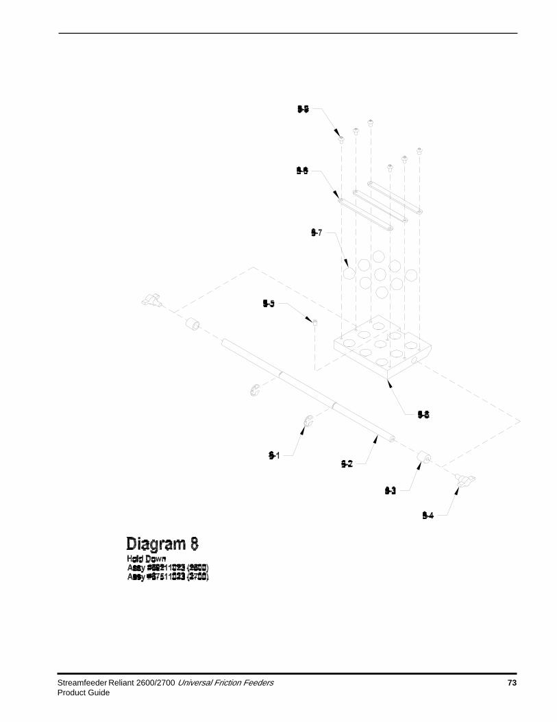
Streamfeeder Reliant 2600/2700 Universal Friction Feeders 73Product Guide

9: ELECTRICAL COMPONENTSASSEMBLY #69211002 (2600) OR #67511002 (2700)
DIAGRAM PART NUMBER QTY DESCRIPTION NUMBER9-1 1 Base Plate 44692002 (2600) 44630002 (2700)9-2 1 Board Stepper Drive BLD72-5 446490309-3 1 Grommet Rubber 446490549-4 1 Board Power DC 5V & 12V 2.5 X 4.25 44649033or 1 POWER SUPPLY, 5V&12V 9017459-5 1 Bracket Power Supply Mounting 44649036or 1 BRACKET, POWER SUPPLY 9018109-6 1 Motor Drive Stepper Assembly 535113909-7 1 Motor Mount 446300119-8 1 Pulley 18T 1/2 Bore W/Flange & Hub 44350053 2 Screw Socket Set 10-32 X 1/8” LG 000033529-9 4 Foot Recessed 5/8 Cylindrical 446420429-10 1 Nut Hex 6-32 Zinc 000021139-11 1 Fan Assembly ST/Reliant Cooling 649110359-12 1 Transformer Power 300VA 446830259-13 1 Bracket Mounting CPU Board 446490389-14 1 Board I/O Expansion 446750359-15 4 Standoff Male/Female 6-32 X 1 446490489-16 1 Board ES CPU 44675037NS 16 Cable Tie Wrap 435SO263NS 2 Terminal Female 44649046NS 34 Sheathing #O HP Black 44649085NS 1 Cable Ribbon 2 Inch 50 Pin 44675036NS 4 Terminal Disconnect Female 22-18 ga 53500045NS 4 Joint Wire Crimp Style 53500152NS 2 Terminal Disc Female .020 22-18 AWG 53500254NS 1 Cable DC Power Supply Assy AC Input 63011006NS 1 Cable Ground Wire Assembly 63011007NS 1 Harness Safety Interlock 64911001NS 1 Harness Sheet Sensor 64911002NS 1 Harness DC Power Supply 64911003NS 1 Harness Drive Control 64911007*NS 2 Holder Adhesive Wire 23500079*NS 3 Cable Tie Wrap 435SO263*NS 1 Power Cord (115V Models Only) 53511020*NS 1 Power Cord / Allen Wrench Set (230V Only) 53522210*NS 1 (DM) Dual Mode (EPROM) 63511003*NS 1 (CM) Continuous Mode (EPROM) 63511004*NS 1 (PM) Presentation Mode (EPROM) 63511005
(CM), (DM), (PM): Indicate feature availability specific to continuous, dual, and/or presentation modefeeders.
*Part is not included with assembly #67511002 or #69211002 and must be ordered separately.

Streamfeeder Reliant 2600/2700 Universal Friction Feeders 75Product Guide

76 Streamfeeder Reliant 2600/2700 Universal Friction FeedersProduct Guide
10: BASE FEATURES 1
DIAGRAM PART NUMBER QTY DESCRIPTION NUMBER
10-1 2 Mount Front Base Plate 44675003
10-2 2 Mount Back Base Plate 44675004
10-3 2 (DM,PM) T Handle Screw Assembly 43511022
10-4 1 Cover Bottom Protective 44692008 (2600) 44675022 (2700)
10-5 1 Bracket Rubber Spacer 44640009
10-6 1 Support O Ring Cover 43555068
10-7 1 (DM,PM) Sensor ST Sheet Assembly 64911011
10-8 1 Switch Safety Interlock Assembly 64911009
10-9 2 Shaft Top Cover Hinge Mount 44640011
10-10 2 Hinge Top Cover Mount 44640012
10-11 1 Side Guide Right 2624 44640003 1 Label Warning 44600005
10-12 1 Side Guide Left 2624 44640002 1 Label Warning 44600005
10-13 1 Shell Reliant 44692001 (2600) 44675001 (2700)
10-14 1 Plug 2 Hole Cover 44500061 1 Label, Belt Routing 44500071
10-15 1 Label Warning (For Protective Cover) 44600004
NS 1 Belt Tensioner Assembly 23511290
NS 2 Guard Accordion Rear 44600001
NS 1 (DM, PM) Holder Adhesive Wire 23500079
(CM), (DM), (PM): Indicate feature availability specific to continuous, dual, and/or presentation modefeeders.

Streamfeeder Reliant 2600/2700 Universal Friction Feeders 77Product Guide

78 Streamfeeder Reliant 2600/2700 Universal Friction FeedersProduct Guide
11: BASE FEATURES 2
DIAGRAM NUMBER QTY DESCRIPTION P/N 2600 P/N 2700
11-1 1 Module AC Power Entry (w/o fuse) 44649034 44649034 2 Fuse 3A 250V Slo-Blo GMD 5 X 20mm 53500006 53500006
11-2 (DM) 1 Select Switch Harness Assembly 67511026 67511026
11-3 1 Harness Fault/Reset Switch Assembly 67511034 67511034
11-4 (CM,PM) 1 Graphic Standard Lower 44692006 44675016 (DM) 1 Graphic Mode Select 44692005 44675027
11-5 1 Cover Plate 44699016 44699016
11-6 1 Graphic Standard Upper 44692004 44675017
11-7 1 Harness Potentiometer Assembly 67511030 67511030
(CM), (DM), (PM): Indicate feature availability specific to continuous, dual, and/or presentation modefeeders.

Streamfeeder Reliant 2600/2700 Universal Friction Feeders 79Product Guide

80 Streamfeeder Reliant 2600/2700 Universal Friction FeedersProduct Guide
12: SUPPORT STANDASSEMBLY #43511200
NOTE: THIS ASSEMBLY STANDARD ONLY ON PRESENTATION & DUAL MODE FEEDERS
DIAGRAM PART NUMBER QTY DESCRIPTION NUMBER
12-1 2 Foot Leveling 43500201
12-2 1 Support Stand 43500200
12-3 2 Knob Large Black 23500093 2 SHCS 1/4-20 X 1/2” LG 00002360
12-4 4 SHCS 10-32 X 1/2” LG 00002315 4 Washer Flat #10 00002607

Streamfeeder Reliant 2600/2700 Universal Friction Feeders 81Product Guide
13: STANDARD MATERIAL HOLD DOWN (QTY 2)ASSEMBLY #23511008
NOTE: THIS ASSEMBLY STANDARD ONLY ON PRESENTATION & DUAL MODE FEEDERS
DIAGRAM PART NUMBER QTY DESCRIPTION NUMBER
13-1 1 Knob Wing #10 w/o Screw 23500076
13-2 1 SHCS 10-32 X 1/2” LG 00002315
13-3 1 Bracket Universal Guide Bar 23500051
13-4 1 Bar Universal Guide 23500050
13-5 1 Washer Flat #10 00002607
13-6 1 SHCS 10-32 X 3/8” LG 00002310
13-7 1 Spring Material Hold Down 23500102
13-8 1 BHCS 8-32 X 1/4” LG 00002210

82 Streamfeeder Reliant 2600/2700 Universal Friction FeedersProduct Guide
Stepper Motor Drive Board
Kick Current Adjust %
High Voltage AC In
1213 11 10
13 12 11
489 7 6 5 3 2 1
23 1
M
Low Voltage AC In
Optional Jumper Settings
Expansion Board
Reliant 2600/2700 Dual Mode w/o External Run OptionTransformer

Streamfeeder Reliant 2600/2700 Universal Friction Feeders 83Product Guide
CPU Board
Expansion Board
NOTE! Cycling power is necessary for new mode to take effect.
Reliant DUAL Mode
9 Electrical Components

84 Streamfeeder Reliant 2600/2700 Universal Friction FeedersProduct Guide
Jump
er J
P3 m
ust
be r
emov
ed.
Expansion Board
Reliant Continuous Mode w/External Run Dry Contact

Streamfeeder Reliant 2600/2700 Universal Friction Feeders 85Product Guide
Expansion Board
Jumper JP3 must be removed.
Note! External Run does not operate in Presentation Mode.
Reliant Dual Mode w/External Run 3-28VDC

86 Streamfeeder Reliant 2600/2700 Universal Friction FeedersProduct Guide
Jumper JP3 must be removed.
Expa
nsio
n Bo
ard
Note! External Run does not operate in Presentation Mode.
Reli
ant
Dual
Mod
e w/
Powe
red
Exte
rnal
Run

Streamfeeder Reliant 2600/2700 Universal Friction Feeders 87Product Guide
Notes
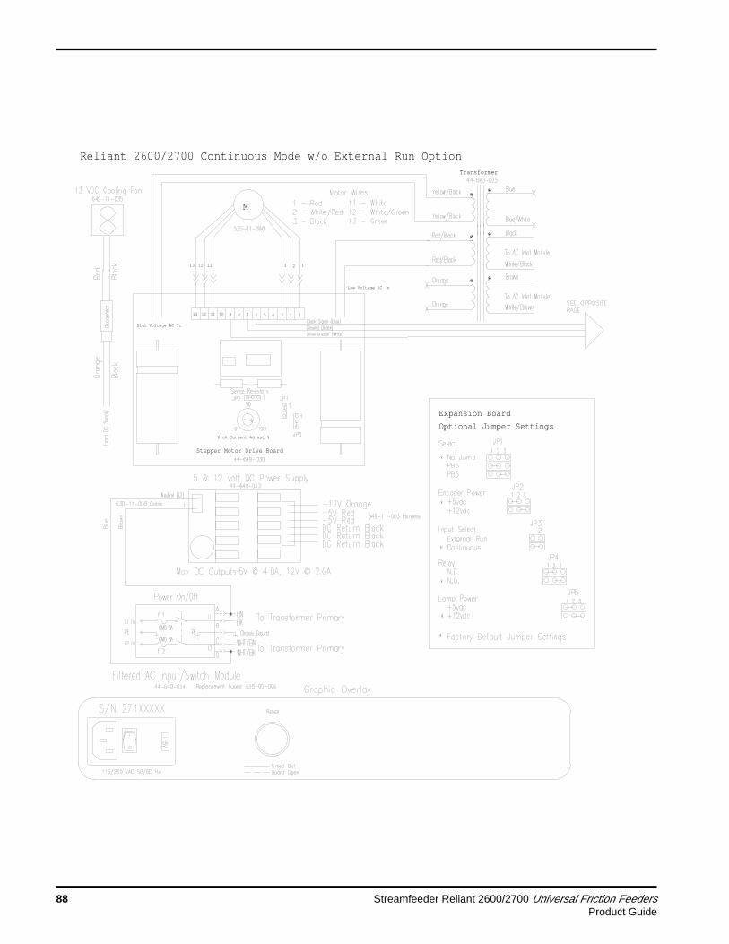
88 Streamfeeder Reliant 2600/2700 Universal Friction FeedersProduct Guide
Stepper Motor Drive Board
Kick Current Adjust %
High Voltage AC In
1213 11 10
13 12 11
489 7 6 5 3 2 1
23 1
M
Low Voltage AC In
Optional Jumper Settings
Expansion Board
Reliant 2600/2700 Continuous Mode w/o External Run OptionTransformer

Streamfeeder Reliant 2600/2700 Universal Friction Feeders 89Product Guide
CPU Board
Expansion Board
Reliant CONTINUOUS Mode

90 Streamfeeder Reliant 2600/2700 Universal Friction FeedersProduct Guide
Jump
er J
P3 m
ust
be r
emov
ed.
Expa
nsio
n Bo
ard
Reli
ant
Cont
inuo
us M
ode
w/Ex
tern
al R
un D
ry C
onta
ct

Streamfeeder Reliant 2600/2700 Universal Friction Feeders 91Product Guide
Expa
nsio
n Bo
ard
Jump
er J
P3 m
ust
be r
emov
ed.
Reli
ant
Cont
inuo
us M
ode
w/Ex
tern
al R
un 3
-28V
DC

92 Streamfeeder Reliant 2600/2700 Universal Friction FeedersProduct Guide
Expa
nsio
n Bo
ard
Jumper JP3 must be removed.
Reli
ant
Cont
inuo
us M
ode
w/Po
were
d Ex
tern
al R
un

Streamfeeder Reliant 2600/2700 Universal Friction Feeders 93Product Guide
Notes

94 Streamfeeder Reliant 2600/2700 Universal Friction FeedersProduct Guide
Stepper Motor Drive Board
Kick Current Adjust %
High Voltage AC In
1213 11 10
13 12 11
489 7 6 5 3 2 1
23 1
M
Low Voltage AC In
Optional Jumper Settings
Expansion Board
Reliant 2600/2700 Presentation Mode Electrical WiringTransformer

Streamfeeder Reliant 2600/2700 Universal Friction Feeders 95Product Guide
CPU Board
Expansion Board
Reliant PRESENTATION Mode

96 Streamfeeder Reliant 2600/2700 Universal Friction FeedersProduct Guide
CPU
Boar
d
Reli
ant
2600
/270
0 Em
erge
ncy
Stop
Opt
ion

Streamfeeder Reliant 2600/2700 Universal Friction Feeders 97Product Guide
Notes

98 Streamfeeder Reliant 2600/2700 Universal Friction FeedersProduct Guide
Stepper Motor Drive Board
Kick Current Adjust %
High Voltage AC In
1213 11 10
13 12 11
489 7 6 5 3 2 1
23 1
M
Low Voltage AC In
Optional Jumper Settings
Expansion Board
Reliant 2600/2700 BryceTransformer

Streamfeeder Reliant 2600/2700 Universal Friction Feeders 99Product Guide
CPU Board
Expansion Board
Reliant Bryce

100 Streamfeeder Reliant 2600/2700 Universal Friction FeedersProduct Guide
Stepper Motor Drive Board
Kick Current Adjust %
High Voltage AC In
1213 11 10
13 12 11
489 7 6 5 3 2 1
23 1
M
Low Voltage AC In
Optional Jumper Settings
Expansion Board
Reliant 2600/2700 DatatechTransformer

Streamfeeder Reliant 2600/2700 Universal Friction Feeders 101Product Guide
CPU Board
Expansion Board
Reliant Datatech

102 Streamfeeder Reliant 2600/2700 Universal Friction FeedersProduct Guide
Stepper Motor Drive Board
Kick Current Adjust %
High Voltage AC In
1213 11 10
13 12 11
489 7 6 5 3 2 1
23 1
M
Low Voltage AC In
Transformer
Reliant 2700 w/RSI Interface

Streamfeeder Reliant 2600/2700 Universal Friction Feeders 103Product Guide
CPU Board
Expansion Board
Dip Switch Settings

104 Streamfeeder Reliant 2600/2700 Universal Friction FeedersProduct Guide

Streamfeeder Reliant 2600/2700 Universal Friction Feeders 105Product Guide

106 Streamfeeder Reliant 2600/2700 Universal Friction FeedersProduct Guide
BLU
BLU/WHT
BLK
WHT/BLK
BRN
WHT/BRN
ORG
ORG
RED/BLK
RED/BLK
YEL/BLK
YEL/BLK
9VAC
Not used
LOW VOLTAGE
(Approx. 4.5VAC)
HIGH VOLTAGE
(Approx. 40 VAC)
VAC
NOMINAL
50/60 Hz
110-120
"A"
BLU/WHT
BLK
WHT/BLK
BRN
WHT/BRN
BLU
NOMINAL
50/60 Hz
"B"120-130
VAC
RED/BLK
YEL/BLK
YEL/BLK
(Approx. 40 VAC)
HIGH VOLTAGE
LOW VOLTAGE
(Approx. 4.5 VAC)
ORG
ORG
RED/BLK
Not used
9VAC
BLU/WHT
BLK
WHT/BLK
BRN
WHT/BRN
BLU
NOMINAL
50/60 Hz
"C"100-110
VAC
RED/BLK
YEL/BLK
YEL/BLK
(Approx. 40 VAC)
HIGH VOLTAGE
LOW VOLTAGE
(Approx. 4.5 VAC)
ORG
ORG
RED/BLK
Not used
9VAC
BLU/WHT
BLK
WHT/BLK
BRN
WHT/BRN
BLU
NOMINAL
50/60 Hz
"D"220-230
VAC
RED/BLK
YEL/BLK
YEL/BLK
(Approx. 40 VAC)
HIGH VOLTAGE
LOW VOLTAGE
(Approx. 4.5 VAC)
ORG
ORG
RED/BLK
Not used
9VAC
BLU/WHT
BLK
WHT/BLK
BRN
WHT/BRN
BLU
NOMINAL
50/60 Hz
"E"240-245
VAC
RED/BLK
YEL/BLK
YEL/BLK
(Approx. 40 VAC)
HIGH VOLTAGE
LOW VOLTAGE
(Approx. 4.5 VAC)
ORG
ORG
RED/BLK
Not used
9VAC
BLU/WHT
BLK
WHT/BLK
BRN
WHT/BRN
BLU
NOMINAL
50/60 Hz
"F"200-208
VAC
RED/BLK
YEL/BLK
YEL/BLK
(Approx. 40 VAC)
HIGH VOLTAGE
LOW VOLTAGE
(Approx. 4.5 VAC)
ORG
ORG
RED/BLK
Not used
9VAC
PRIMARY SECONDARY PRIMARY SECONDARY
SECONDARYPRIMARYSECONDARYPRIMARY
SECONDARYPRIMARYSECONDARYPRIMARY
NO CONNECTION NO CONNECTION
Standard wiring for most North American applications Standard wiring for Continental Europe, some 230V US applications
North America where voltage is over 120V Standard wiring for U.K., Australia, New Zealand
Standard wiring for Japan Some Japanese (200V) applications, some US applications for 208V
L1
N
L1
L2
L1
N
L1
N
L1
L2
L1
L2

Streamfeeder Reliant 2600/2700 Universal Friction Feeders 107Product Guide
SW1
SW2
SW3
SW4
R R
+-

108 Streamfeeder Reliant 2600/2700 Universal Friction FeedersProduct Guide
Unipolar DC Stepping Motor Drive Boards #44-649-030 and #535-00-467
Low Voltage AC In
12
34
67
89
511
1213
10
High Voltage AC In
+
1312
113
21
M
13 P
in M
otor
Cou
pler
Pin
Ass
ignm
ents
1
- Mo
tor
Phas
e 1
2
- Mo
tor
Phas
e 3
3
- Ph
ases
1 &
3 C
ommo
n
4
- No
t Us
ed
5
- No
t Us
ed
6
- Cl
ock
Inpu
t
7
- 0
VDC/
Grou
nd
8
- No
t Us
ed
9
- Mo
tor
On/O
ff (
Acti
ve L
ow)
10 -
Not
Use
d
11 -
Pha
ses
2 &
4 Co
mmon
12 -
Mot
or P
hase
2
13 -
Mot
or P
hase
4
NOTE
S -
Driv
e is
rat
ed a
t 10
amp
s DC
cur
rent
max
.
Moto
r Ki
ck C
urre
nt A
djus
tmen
t se
t at
85
- 90
%.
Jump
er S
etti
ngs
Func
tion
Nega
tive
Goi
ng C
lock
s
Posi
tive
Goi
ng C
lock
s
Term
inal
5 =
CCW
Term
inal
5 =
Dir
ecti
on
Faul
t De
tect
ion
Enab
led
Faul
t De
tect
ion
Disa
bled
FACT
ORY
DEFA
ULTS
JP1
1 -
2
2 -
3
X
X
X
X
1 -
2
JP2
X
X
1 -
2
2 -
3
X
X
2 -
32
- 3
X
X
JP3
1 -
2
2 -
3
X
X
21 3Re
d LE
D -
On S
tead
y
Red
LED
- Fa
st B
link
Red
LED
- Sl
ow B
link
Shor
t in
Mot
or,
Cabl
e, o
r on
Boa
rd
Open
in
Moto
r, C
able
or
on B
oard
Grou
nd F
ault
(Vo
ltag
e sh
orte
d to
0 v
olts
)
Faul
t De
tect
ion
Prot
ecti
on L
ED I
ndic
atio
n
Kick Current Adjust %
Stepper Motor Drive Board

Streamfeeder Reliant 2600/2700 Universal Friction Feeders 109Product Guide
Reli
ant
2700
DIP
Swi
tch
Sett
ings
Cont
inuo
us M
ode
Only

Streamfeeder Reliant 2600/2700 Universal Friction Feeders 111Product Guide
10 Technical Troubleshooting
! ! !Only a qualified technician should performelectrical troubleshooting activities. This unitoperates on 115V or 230V electrical power.Bodily contact with these voltages can result inserious injury or death.
The “drive” consists of the AC power supply (transformer),the stepper motor drive board, and the motor. The “controls”consist of the DC power supply, the CPU board, any ribboncables and wiring harnesses, and the sensors. Once it isdetermined that you have a drive or a controls problem, thenext thing to check is the power supply for that section. Thetable that follows is designed to be a “quick lookup” for aproblem you may be having. Wiring and board diagrams alsocontained in this manual are provided for reference andcomponent recognition and connection during troubleshooting.
General TroubleshootingTerms
IMPORTANT Reliant Models 2600 and 2700 have many various electricalcontrol options available. To effectively troubleshoot you needto determine how your feeder has been configured. One or moreof these options are installed during the manufacturing processbecause the machine is configured to order. Refer to theelectrical wiring diagrams elsewhere in this manual. Here youwill find the information that you need to determine theconfiguration of your machine.
To begin, remove the four screws securing the electricalcomponent access cover. The speed control is mounted on thiscover plate. Next look at the CPU board ROM label. This labelhas a few lines of text written on it. The top line of the text willhave a number you should look for:
1. Number 63511003 indicates the machine has Dual Mode(continuous run and presentation mode) capabilities.
2. Number 63511004 indicates the machine has ContinuousMode capability only.
3. Number 63511005 indicates the machine hasPresentation Mode capability only.
If any other number appears on the top line, your machine is nota factory standard, and has custom controls. If this is the case,contact the dealer through which you purchased the machine forfurther details.

112 Streamfeeder Reliant 2600/2700 Universal Friction FeedersProduct Guide
Next look at the graphic overlay on your machine. This overlayhas a serial number printed on it near the power switch. Thewiring diagrams show a representation of the graphic overlayassociated with that machine. Try to find the overlay drawingthat most closely matches your machine.
You may need to use a combination of two diagrams dependingupon the options you may have. For example: You havedetermined from the ROM label that your machine has DualMode capabilities. The first document you will use for referenceis the one titled Reliant Dual Mode w/o External Run Option.From this document you see that the graphic overlay may ormay not match the overlay on your machine. Does yourmachine have an External Run Input connector? If so, look atthe Dual Mode option diagrams that follow. There are severalexternal run options available. You will need to look at thewiring to determine which option you have.
The table that follows is designed to be a “quick lookup” for aproblem you may be having. Wiring and board diagrams alsocontained in this manual are provided for reference andcomponent recognition and connection during troubleshooting.
Many of the wiring harnesses have numberedlabels on them. Try to match the harnessnumbers to help you determine the option(s) youhave.
If your machine has a sheet detect sensor, it haseither Presentation or Dual Mode controls. Ifyour machine does not have a sheet detect sensor,it has Continuous Mode controls.
TIP
TIP

Streamfeeder Reliant 2600/2700 Universal Friction Feeders 113Product Guide
No power to feeder whenpower switch is turned on
NOTE
This power module isdesigned to hold 5mm x20mm fuses, as well as 1.25”x .25” fuses. The machineships from Streamfeeder’sfacility with 5mm x 20mmfuses.
Fuses blow on power up
NOTE
A fuse failure indicates aproblem with the last itemconnected before failureoccurs.
Problem Solution
1. Make sure there is power present at the AC main where the feeder is plugged in.
2. Check three-wire AC power cord for integrity at all three points.
3. Remove power cord from AC input switch module and disconnect the four spaceconnector leads located on the back of the module inside the feeder.
4. Check the two fuses located inside the feeder’s input power module. BOTH fusesmust be present and test good.
a. Observe the voltage label showing through the window on the fuse housingfor the proper orientation when the holder is re-inserted.
b. A small screwdriver inserted under the tab will allow you to pry open the fusehousing. Remove the red fuse holder. If the smaller 5mm x 20mm fuse ispresent, verify that the metal tab “finger” is holding the fuse in the forwardposition. Make sure it has not allowed the fuse to slide back toward theoutside of the feeder and away from where contact with the metal pressurepoints inside the module body is made.
c. Use an ohmmeter to test the fuses. A visual inspection will not always besufficient to determine fuse integrity. If necessary, replace with fuses of thesame rating only.
5. Reconnect power cable and, with power switch turned “on,” check for presence ofAC at the output spade connectors on the back of the module where thetransformer primary lead connections are made.
6. If steady AC power is not measured as in the previous step, the module’s internalcontacts are most likely worn, and the module must be replaced.
1. Install known good fuses of same rating only.
2. Disconnect all AC loads from the input:
a. The transformer primary.b. The DC supply’s AC input leads.c. Remove the red and yellow wire pairs from the stepper motor drive board.
3. Reconnect AC loads one item at a time while alternately applying power betweennew connections. Connect each load as follows one at a time to determine thefaulty part:
a. Connect the transformer primary leads to the AC input module.b. Connect leads to the two-pin AC input connector of the DC power supply.c. Connect the red and yellow wire pairs of the transformer secondary to the
stepper motor drive board.
Table 10-1. Quick-Look Troubleshooting

114 Streamfeeder Reliant 2600/2700 Universal Friction FeedersProduct Guide
If the input power module fuse holder is installed in the 230V position, and the linepower is at 115V, the feeder will have noticeably decreased power.
The drive board must have its “kick current” dial set to at least 90%.
1. Verify green LED on the stepper motor drive board is illuminated. If not, verifytransformer secondary leads measure correct voltages: 40 VAC across yellow pairof wires, and 4.5 VAC across red pair of wires. Go to section titled “Testing thetransformer” for further information. If green LED is not illuminated and thetransformer voltages test good, replace drive board. Otherwise, continue with nextstep.
2. Look at the red LED on the stepper motor drive board. Is it illuminated?
a. If yes, go to section titled “Drive board red LED illuminated”.b. If no, continue with next step.
3. Remove white wire from pin 9 of the stepper motor drive board 13-pin connector.This is the drive disable line coming FROM the CPU board on connector J8 pin 2.The drive board is enabled by default when no connection is made at pin 9.
4. Cycle the feeder. If the motor runs, the output on connector J8 pin 2 of the CPUboard is bad, and the CPU board must be replaced. If not, continue with next step.
5. Measure for the presence of pulse train. The pulse train comes FROM the CPUboard connector J8 pins 1 (signal) and 3 (ground), and goes TO the stepper motordrive board at pins 6 (signal input) and 7 (ground). Test points are pins 6 and 7 onthe 13-terminal connector to the drive board.
a. Power-up the feeder and verify the reset button is not illuminated. If a resetcannot be accomplished refer to the section titled “On/Off beeping sound isheard, reset button is illuminated, and pressing button does not reset fault”.
b. Verify signal is present on pins 6 and 7. When the speed control knob is fullyCCW, no pulse or a very low pulse frequency will be measured. When thespeed control is fully CW, the frequency could be measured as high as 8.2kHz. It is recommended to set the run speed at about 50% where thefrequency measured should be somewhere between 3000 and 4000 Hz.
Decreased powerexperienced after fuse isreplaced
Never apply more than 125Vwhen the fuse holder is in the115V position. Applying 230Vto the feeder when the fuseholder is in the 115V positionwill damage the feeder’sinternal electronics.
Decreased powerexperienced after driveboard is replaced
Motor does not run, is noisy,makes a “growling” sound,or runs in reverse
NOTE
A digital multimeter withfrequency measurementcapabilities is necessary forthe following tests. If yourmeter does not have the abilityto make a frequencymeasurement, an oscilloscopemay be used instead.
NOTE
This test requires a meter thathas frequency measurementcapabilities, or anoscilloscope.
NOTE
The frequency measured heredirectly affects the speed ofthe motor.
Problem Solution
!
Table 10-1. Quick-Look Troubleshooting (continued)

Streamfeeder Reliant 2600/2700 Universal Friction Feeders 115Product Guide
Motor does not run, is noisy,makes a “growling” sound,or runs in reverse(continued)
Drive board red LEDilluminated
IMPORTANTThe stepper motor drive boardhas been designed to protectitself if motor problems occur.If a problem with the motorwires or motor is found andcorrected, the board will stilldrive a good motor aftercorrection is made. However,the board cannot protect itselffrom transient voltage spikesand/or power sags orbrownouts. It is highlyrecommended that in plantswhere power problems areevident or in question, a highquality surge suppressor orline conditioner should beemployed for added protection.
Testing stepper motor driveboard output pins
NOTE
A digital multimeter is requiredfor these tests.
NOTE
Measuring zero volts dropacross one of these pins maybe evidenced by blowing fuseson power-up. See sectiontitled “Fuses blow on powerup”.
c. Check integrity of both ends of drive wiring harness between the CPU boardconnector J8 and the 13-terminal connector to the drive board.
d. Using a digital multimeter or an oscilloscope, measure the amplitude of thepulse train and verify that it is at least 2.3VDC.
e. If pulse test results are good, replace the stepper motor drive board. If thepulse tests results are negative, the pulse output on connector J8 of the CPUboard is bad, and the control assembly must be replaced.
1. Slow Blink: (about once per second) indicates a SHORT in motor, motor cable, ordrive power component.
a. Check integrity of motor wires and/or cable. None of the wires should beexposed, and should have their full insulation so that they may not short toeach other or any other part of the machine.
b. If wires look OK, go to section titled “Testing stepper motor drive board outputpins.”
c. If stepper motor drive board test results are positive, replace the motor. Forfurther information, see the section titled “Testing motors.”
2. Fast Blink: (multiple times per second) indicates an OPEN in motor, motor cable, ordrive component.
a. Check integrity of motor wires and/or cable. None of the wires should measureopen, or be disconnected or loose from their terminals.
b. If wires check OK, go to section titled “Testing stepper motor drive board outputpins.”
c. If stepper motor drive board test results are positive, replace the motor. Forfurther information, see the section titled “Testing motors.”
3. On Steady: indicates a ground fault (wire shorted to zero volts).
a. Remove ground fault.
1. Remove 13-terminal plug-in motor wire coupler from the drive board.
2. Test motor phase pins. Note: A digital multimeter is required for these tests.
a, Set the multimeter to Diode Test.b. Place the RED meter lead on one of the leads between the large black sense
resistors located at the center of the drive board located above jumper JP2.c. Touch the BLACK meter lead to each phase terminal (pins 1, 2, 12, and 13).
This should give readings between 0.450V and 0.550V. If any readings aresignificantly greater than or less than 0.450V to 0.55V, then the unit is faultyand must be replaced.
3. Test motor common pins:
a. Touch the BLACK meter lead to the positive lead of the large blue capacitor onthe left side of the board, which is located below the red fault indicator LED.
b. Touch the RED meter lead to pins 3 and 11. These pins should give readingsbetween 0.450V and 0.550V. If any readings are significantly greater than orless than 0.450V to 0.55V, then the unit is faulty and must be replaced.
Problem Solution
Table 10-1. Quick-Look Troubleshooting (continued)

116 Streamfeeder Reliant 2600/2700 Universal Friction FeedersProduct Guide
Fan does not operate/Testing DC power supply
NOTE
The DC supply has dualoutputs: 5 and 12 volts DC.
NOTE
When the output is shorted, afaintly audible clicking soundcan be heard coming from thesupply. This is the powersupply protecting itself fromfailure due to a short on itsoutput.
IMPORTANTContinued operation of themachine without the coolingfan working properly willcause further damage to theinternal electroniccomponents.
CPU board “heartbeat”pulse not present
Problem Solution
1. Refer to the DC power supply board diagram. Remove 6-pin DC wiring harnessconnector from output of DC supply. Measure the supply’s output pins for thepresence of DC power.
a. If voltages are not present, verify AC power is being applied to AC input.b. Also check the fuse on the supply’s AC input. If the fuse is bad, and replacing it
causes fuse failure to occur again, replace the supply.c. If the fuse is good, AC power is being applied, and DC power cannot be
measured, replace supply.
2. Verify good electrical connections to pins in DC wiring harness 6-pin quickdisconnect plug. Reconnect harness.
3. Check for shorted wires in the DC wiring harness on output of supply. A short willcause the supply to shut down. The power supply should operate normally after theshort is removed.
4. Test DC wire harness 4-pin plug in connectors to the CPU and Expansion Boardsfor the presence of 5 and 12 volts DC.
5. Test wire harness to fan quick-disconnect plug for the presence of 12VDC.
6. Replace fan.
1. Two LEDs are located on the CPU board. The “heartbeat” LED is the green LED.The green LED should blink at regular intervals under normal operation when thefeeder is powered on. Make sure the front safety shield is closed completely, andthat no error conditions are present.
2. Check output of DC power supply. See section titled “Fan does not operate/TestingDC power supply.”
3. Verify ribbon cable integrity between CPU board and Expansion Board.
4. Check that the ROM and RAM chips are seated properly in their sockets. Improperlyseated chips may cause the CPU board to indicate a problem by illuminating the redLED located next to the green “heartbeat” LED. The red LED should not illuminate.
5. Replace Reliant Control Assembly.
6. Replace ROM chip.
Table 10-1. Quick-Look Troubleshooting (continued)

Streamfeeder Reliant 2600/2700 Universal Friction Feeders 117Product Guide
On/Off beeping sound isheard, reset button blinks,and pressing button doesnot reset fault
NOTE
Power must be on during thefollowing tests. Exercisecaution.
NOTE
The following steps assumethe output of the DC powersupply is working and both 5and 12 volts is present at theCPU and Expansion Boardinput connectors.
NOTE
The following steps assumethe blinking green “heartbeat”LED is present on the CPUboard. If not, see sectiontitled “CPU board ‘heartbeat’pulse not present.”
Steady beep is heard, resetbutton is illuminated, andpressing button does notreset fault
NOTE
Power must be on during thefollowing tests. Exercisecaution.
Problem Solution
1. Remove reset button harness from Expansion Board connector J6.
2. Using a small metal blade screwdriver, short pins 3 and 4 together on ExpansionBoard connector J6.
3. Did shorting these pins reset the feeder?
a. Yes: The reset switch harness assembly is faulty. Repair or replace asnecessary.
b No: Verify continuity at reset button closure, reconnect the reset buttonharness to the Expansion Board connector J6. Press the reset button aftertrying each of the following steps:
4. Verify that the discharge safety shield is closed completely.
5. Is E-Stop option installed?
a Yes: Go to step 6.b. No: Go to step 7.
6. Verify E-Stop switch is out of the locking stop position by twisting and pulling thered knob out.
7. Remove the safety interlock harness from connector J7 of the CPU board.
8. Using a small metal blade screwdriver, short pins 1 and 2 together on CPUboard connector J7, keep them shorted, and press the reset button. Doespressing the reset button reset feeder?
a. Yes: Go to step 9.b. No: Go to step 10.
9. Connector J7 input is good. Check the integrity of safety interlock harnesses andthe safety interlock switch. If E-Stop option is installed, check the integrity of thisharness and switch assembly as well. Repair or replace as necessary.
10. Replace Reliant Control Assembly.
11. Replace ROM chip.
1. Verify firm connection and that the integrity of the ribbon cable connectedbetween the CPU and Expansion Boards is intact.
2. Remove reset button harness from Expansion Board connector J6.
3. Using a small metal blade screwdriver, short pins 3 and 4 together on ExpansionBoard connector J6. Did shorting these pins reset the feeder?
a. Yes: The reset switch harness assembly is faulty. Repair or replace asnecessary.
b No: Verify reset switch integrity, reconnect to Expansion Board connectorJ6 and go to step 4.
Table 10-1. Quick-Look Troubleshooting (continued)

118 Streamfeeder Reliant 2600/2700 Universal Friction FeedersProduct Guide
4. Verify the sheet sensor’s power-on green LED is illuminated. Is the green LEDilluminated?
a. Yes: Go to step 5.b. No: Go to step 7.
5. Verify the sheet sensor’s yellow LED sensing indicator illuminates when the sensoris covered, and goes dark when the sensor is uncovered. Is the yellow LEDilluminated when the sheet sensor is covered, and dark when the sensor isuncovered?
a. Yes: Go to step 6.b No: Go to step 7.
6. Cover the sensor so that the yellow sensing LED is illuminated and press the resetswitch. Did the feeder reset?
a. Yes: The feeder times-out as it should. Go through feeder setup and makesure the sensor sees the leading edge of the next sheet shortly after a pieceof sheet material is removed from the feeder. If the leading edge of the nextpiece of material is not detected in time, the feeder “times-out” and stops,causing the steady audible beep and reset button lamp to illuminate.
b. No: Got to step 7.
7. Remove the sheet detect sensor harness from CPU connector J6 and measure forthe presence of 12VDC across pins 1 and 3 of connector J6 on the board. Is thevoltage present?
a. Yes: Go to step 8.b. No: Go to step 9.
8. Test sheet sensor input. Using a small metal blade screwdriver, short pins 1 and 2together on CPU board connector J6, keep them shorted, and press the resetbutton. Does the feeder reset?
a. Yes: The sheet sensor input on the CPU board is good. Repair faulty sheetsensor harness and/or replace sheet sensor.
b. No: Go to step 9.
9. Replace Reliant Control Assembly.
10. Replace ROM chip.
Steady beep is heard, resetbutton is illuminated, andpressing button does notreset fault (continued)
NOTE
These steps only apply toPresentation Mode machinesor Dual Mode machinesworking in the PresentationMode.
NOTE
The following steps assumethe output of the DC powersupply is working and both 5and 12 volts is present at theCPU and Expansion Boardinput connectors. If not, seesection titled “Fan does notoperate/Testing DC powersupply.”
NOTE
The following steps assumethe blinking green “heartbeat”LED is present on the CPUboard. If not, see section titled“CPU board “heartbeat” pulsenot present.”
Problem Solution
Table 10-1. Quick-Look Troubleshooting (continued)

Streamfeeder Reliant 2600/2700 Universal Friction Feeders 119Product Guide
Testing the External RunDry Contact input
Testing the External Runinput 3-28 volts DC
Dual Mode machines:
1. External Run only functions in Continuous Mode. Verify mode switch is not set forPresentation Mode.
2. Verify jumper block JP3 is removed from the expansion board.
3. Verify the integrity of the mode selector switch and harness, and that it is closedacross pins 1 and 2 of connector J3 on the Expansion Board.
4. Shorting pin 1 to pin 5 of connector J4 on the Expansion Board should cause thefeeder to run. If not, replace the Reliant Control Assembly.
Continuous Mode machines:
1. Verify jumper block JP3 is removed from the expansion board.
2. Verify the integrity of the Y adapter harness and the external run override switchand harness. Verify that the switch opens and closes across pins 1 and 5 ofconnector J4 on the Expansion Board.
3. Shorting pin 1 to pin 5 of connector J4 on the Expansion Board should cause thefeeder to run. If not, replace the Reliant Control Assembly.
Dual Mode machines:
1. External Run only functions in Continuous Mode. Verify mode switch is not set forPresentation Mode.
2. Verify jumper block JP3 is removed from the expansion board.
3. Verify the integrity of the mode selector switch and harness, and that it is closedacross pins 1 and 2 of connector J3 on the Expansion Board.
4. Applying a voltage between 3 and 28 VDC to connector J9 on the ExpansionBoard should cause the feeder to run. If not, replace the Reliant ControlAssembly. If a power supply is not available to you, you may test the input using a9V battery. To test the input using a 9V battery:
a. Connect the positive terminal of the battery to pin 1 of connector J9.b. Connect the negative terminal of the battery to pin 2 of connector J9.
Continuous Mode machines:
1. Verify jumper block JP3 is removed from the expansion board.
2. Verify the integrity of the Y adapter harness and the external run override switchand harness. Verify that the switch opens and closes across pins 1 and 5 ofconnector J4 on the Expansion Board.
Problem Solution
Table 10-1. Quick-Look Troubleshooting (continued)

120 Streamfeeder Reliant 2600/2700 Universal Friction FeedersProduct Guide
3. With the override switch open, apply a voltage between 3 and 28 VDC toconnector J9 on the Expansion Board. This should cause the feeder to run. If not,replace the Reliant Control Assembly. If a power supply is not available to you, youmay test the input using a 9V battery. To test the input using a 9V battery:
a. Connect the positive terminal of the battery to pin 1 of connector J9.b. Connect the negative terminal of the battery to pin 2 of connector J9.
4. With the override switch closed, remove the voltage from Expansion Boardconnector J9. The override switch shorts pin 1 to pin 5 of connector J4 on theExpansion Board. This should cause the feeder to run. If not, replace the ReliantControl Assembly.
Dual Mode machines:
1. Verify jumper block JP3 is removed from the expansion board.
2. Verify the integrity of the mode selector switch and harness, and that it is closedacross pins 1 and 2 of connector J3 on the Expansion Board.
3. Locate the mechanical relay mounted inside the machine. Determine the voltageof the coil by looking at the label on the relay body. Three possible relays may befound:
a. 24VAC.b. 120VAC.c. 230VAC.
4. Apply the proper voltage to the coil of the relay and listen for contact closure. If therelay contacts do not pull in, replace the relay.
5. Verify contact continuity where the white and black wires are connected to thecontact side of the relay. These wires are also connected to the Expansion Boardconnector J4 across pins 1 and 5. If the contacts or wire leads are bad, continuitycannot be measured. Replace wire leads or replace the relay as necessary.
6. The relay contacts are meant to short pin 1 to pin 5 of connector J4 on theExpansion Board. This should cause the feeder to run. If not, replace the ReliantControl Assembly.
Continuous Mode machines:
1. Verify jumper block JP3 is removed from the expansion board.
2. Verify the integrity of the Y adapter harness and the external run override switchand harness. Verify that the switch opens and closes across pins 1 and 5 ofconnector J4 on the Expansion Board.
3. Locate the mechanical relay mounted inside the machine. Determine the voltageof the coil by looking at the label on the relay body. Three possible relays may befound:
a. 24VAC.b. 120VAC.c. 230VAC.
Problem Solution
Table 10-1. Quick-Look Troubleshooting (continued)
Testing the External Runinput 3-28 volts DC(continued)
Testing the PoweredExternal Run Input
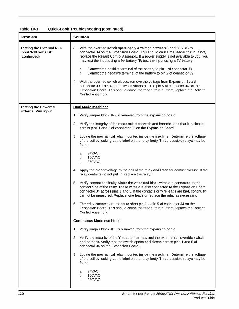
Streamfeeder Reliant 2600/2700 Universal Friction Feeders 121Product Guide
4. With the override switch open, apply the proper voltage to the coil of the relay andlisten for contact closure. If the relay contacts do not pull in, replace the relay.
5. Verify contact continuity where the white and black wires are connected to thecontact side of the relay. These wires are also connected to the Expansion Boardconnector J4 across pins 1 and 5. If the contacts or wire leads are bad, continuitycannot be measured. Replace wire leads or replace the relay as necessary.
6. The relay contacts are meant to short pin 1 to pin 5 of connector J4 on theExpansion Board. This should cause the feeder to run. If not, replace the ReliantControl Assembly.
7. Closing the override switch simply replaces the relay contact closure. This shouldshort pin 1 to pin 5 of connector J4 on the Expansion Board, and cause the feederto run. If not, replace the Reliant Control Assembly.
1. Remove fuse F1 from the Expansion Board and measure across its pins forcontinuity. If continuity is not measured, replace the fuse.
2. Fuse F1 is connected in series with a set of contacts inside the mini relay locatedon the Expansion Board. These contacts are brought out through connector J7.Jumper block JP4 selects the normally open or normally closed set of contacts.The normally open contacts close when the machine is powered on. Test thecontacts:
a. Set jumper block JP4 in the N.O. positionb. Using an ohmmeter, measure across pins 1 and 2 of connector J7. You
should measure an open load.c. Power on the machine. The contacts should close and you should measure
continuity across J7. If not, replace the Expansion Board.
Refer to the wiring diagram of the 6-lead DC Stepping Motor found elsewhere in thismanual.
These motors are NOT repairable, and should never be opened.
The motors used in the Reliant Series of feeders have two windings: three leadsassociated with each winding, for a total of six leads. Each winding has a wire at eachend of the winding, with a wire connected also at the center of the winding. This centertap is also called the “common” wire, while the end wires are called the “phase” wires.Motors are inductors. Inductors are tough to troubleshoot unless there is acatastrophic failure associated with the windings inside the inductor. An ohmmetermay be used to test for catastrophic failures, but is useless when a motor has aproblem that is not catastrophic. Therefore, a motor can still have a problem eventhough it appears there is not a problem as measured with an ohmmeter. The followingare tests that you can make with an ohmmeter:
1. All three leads of each individual winding should measure continuity in anycombination of two. Conversely, an OPEN should NOT be measured in anycombination of two of the three leads tested in a single winding. If an open ismeasured in a single winding, it is a clear indication that the motor is bad andneeds to be replaced.
2. Since there are two separate windings, they need to measure electrically separate
Testing the Powered ExternalRun Input (continued)
Testing the Fault OutputConnector
Testing Motors
Problem Solution
Table 10-1. Quick-Look Troubleshooting (continued)

122 Streamfeeder Reliant 2600/2700 Universal Friction FeedersProduct Guide
from each other. That is, any combination of one lead from one winding to any leadof the other winding should measure as OPEN. If a short is measured betweenwindings, it is a catastrophic failure inside the motor, and it must be replaced.
3. Both windings need to be insulated from the body of the motor. If continuity ismeasured between any motor lead and the body of the motor, a catastrophicfailure has occurred inside the motor and it must be replaced.
Refer to the wiring diagram of the Reliant Series Transformer found elsewhere in thismanual. Note that there are three primary windings and also three secondarywindings: six windings altogether. Most feeders are shipped from Streamfeeder’sfacility with the transformer set up for configurations “A” and “D.” Therefore one of theprimary windings is not used, and will be tied back. (The orange secondary leads arealso not used in the Reliant Series of feeders, and will be tied back). Flipping the fuseholder around in the AC power entry module will set up the feeder for either 115VAC asshown in configuration “A,” or for 230VAC as shown in configuration “D.” Flipping thefuse holder around actually rewires the transformer primary windings as shown inconfigurations “A” and “D.”
Transformers are inductors. Inductors are tough to troubleshoot unless there is acatastrophic failure associated with the windings inside the inductor. An ohmmeter maybe used to test for catastrophic failures, but is useless when a transformer has aproblem that is not catastrophic. Therefore, a transformer can still have a problemeven though it appears there is not a problem as measured with an ohmmeter.Fortunately, transformers very, very rarely fail. So chances are that any problem youmay have that leads you to the transformer is most likely caused by some othercomponent that is a load on the transformer.
The following assumes that all crimp-on connectors are properly connected to thetransformer wires, and are making contact with them, or are NOT crimped onto theinsulation preventing a good electrical connection to the individual wires of thetransformer.
1. The first step to testing a transformer is to remove the secondary windings fromtheir loads. Remove the yellow and red wire pairs from the stepping motor driveboard.
2. Apply the correct power to the transformer primary depending upon the position ofthe fuse holder in the AC power entry module. If the line fuse blows without anyloads connected to the transformer secondary windings, it is likely that it has aninternal short and must be replaced.
3. Using an AC volt meter, measure the voltage across each primary winding. Do notmeasure with one lead of your meter to ground or the chassis, but rather measurethe wire pairs with respect to each other.
a. Measure the yellow pair of wires with a black stripe on them, by putting thered meter lead on one yellow wire, and the black meter lead on the otheryellow wire. (It does not matter which meter lead goes to which transformerwire). You should measure approximately 40VAC between these two wires. Ifnot, the transformer is faulty and must be replaced.
Problem Solution
Table 10-1. Quick-Look Troubleshooting (continued)
Testing Motors (continued)
Testing the Transformer

Streamfeeder Reliant 2600/2700 Universal Friction Feeders 123Product Guide
Problem Solution
Table 10-1. Quick-Look Troubleshooting (continued)
b. Measure the red pair of wires with a black stripe on them, by putting the redmeter l ead on one red wire, and the black meter lead on the other red wire.(It does not matter which meter lead goes to which transformer wire). Youshould measure approximately 4.5VAC between these two wires. If not, thetransformer is faulty and must be replaced.
The following are tests that you can make with an ohmmeter:
1. Each of the six windings has two wires: one lead on each end of them. Make sureyou measure continuity between winding leads. If a winding is measured open, thetransformer is faulty and must be replaced.
2. Next verify that none of the windings are shorted to any other winding. Using yourohmmeter, you should NOT measure continuity from one winding to any of theother five windings. If a short is measured between windings, the transformer isfaulty and must be replaced.
Testing the Transformer(continued)

124 Streamfeeder Reliant 2600/2700 Universal Friction FeedersProduct Guide
Notes

STREAMFEEDER® LIMITED WARRANTY
Streamfeeder, LLC (Streamfeeder) warrants this product to be free from defects inmaterials and workmanship, when used under recommended operating conditions,for a period of two years from the date of original retail purchase.
If you discover a defect during the warranty period, please notify the authorizedStreamfeeder distributor from whom you purchased this product, who will makerepairs at no charge to you. If the defect is not field-repairable, and if you return it toStreamfeeder during the warranty period, Streamfeeder will, at its sole option, repairor replace this product, at no charge to you other than shipping charges to and fromthe Streamfeeder facility in Minneapolis, Minnesota.
If you return this product to Streamfeeder for warranty repair or replacement, pleaseattach to the returned product your name and your company’s name, address,telephone number and fax number; a description of the problem; and a copy of the billof sale or invoice that shows the appropriate serial number for the product. All returnsmust be accompanied by an authorized Streamfeeder Returned Goods Authorization(RGA) number. An authorized RGA number can be obtained from StreamfeederSales/Service Department.
This warranty applies only to products manufactured by Streamfeeder. This warrantydoes not apply if the product has been damaged by accident, abuse, misuse, neglect,improper maintenance, misapplication, or as a result of being attached to equipmentnot supplied by Streamfeeder; if the product has been modified without the writtenpermission of Streamfeeder; or if the product’s serial number has been removed ordefaced. This warranty further does not apply to the failure of any rubber-based orconsumable components, including but not limited to “O” rings, rollers, feed belts,fuses, or bulbs.
ALL IMPLIED WARRANTIES INCLUDING WITHOUT LIMITATION THE IMPLIEDWARRANTY OF FITNESS FOR A PARTICULAR PURPOSE AND THE IMPLIEDWARRANTY OF MERCHANTABILITY ARE HEREBY DISCLAIMED.
Streamfeeder is not responsible for special, incidental, or consequential damagesresulting from any breach of warranty or under any other legal theory, including lostprofits, downtime, goodwill, or damage to or replacement of equipment or property.
This warranty and the remedies set forth above are exclusive and are in lieu of allothers, oral or written, express or implied. There are no warranties that extendbeyond the description on the face hereof. No Streamfeeder employee, distributor, oragent is authorized to make any modification, extension, or addition to this warranty.
Warranty

103 Osborne Road • Minneapolis, MN 55432-3120 USATEL: 763.502.0000 • FAX: 763.502.0100
E-MAIL: [email protected]: www.streamfeeder.com
© 2002 Streamfeeder, LLCPrinted in the USA.
Part No. 00900368