Embed Size (px)
Citation preview

Alcatel-Lucent 9500 MICROWAVE PACKET RADIO for ANSI | RELEASE 4.0.0M P T - G C ( 8 0 G H z W i r e l e s s L i n k s )
Alcatel-Lucent 9500 MICROWAVE PACKET RADIO for ETSI | RELEASE 4.0.0M P T - G C ( 8 0 G H z W i r e l e s s L i n k s )
U s e r M a n u a l3 D B 1 9 0 2 5 A A A A E d i t i o n 2
Alcatel-Lucent ProprietaryThis document contains proprietary information of Alcatel-Lucent and is not to be disclosedor used except in accordance with applicable agreements.Copyright 2012 © Alcatel-Lucent. All rights reserved.

When printed by Alcatel-Lucent, this document is printed on recycled paper.
Alcatel-Lucent assumes no responsibility for the accuracy of the information presented, which is subject to change without notice.
Alcatel, Lucent, Alcatel-Lucent and the Alcatel-Lucent logo are trademarks of Alcatel-Lucent. All other trademarks are the property of their respective owners.
Copyright 2012 Alcatel-Lucent.All rights reserved.
Disclaimers
Alcatel-Lucent products are intended for commercial uses. Without the appropriate network design engineering, they must not be sold, licensed or otherwise distributed for use in any hazardous environments requiring fail-safe performance, such as in the operation of nuclear facilities, aircraft navigation or communication systems, air traffic control, direct life-support machines, or weapons systems, in which the failure of products could lead directly to death, personal injury, or severe physical or environmental damage. The customer hereby agrees that the use, sale, license or other distribution of the products for any such application without the prior written consent of Alcatel-Lucent, shall be at the customer's sole risk. The customer hereby agrees to defend and hold Alcatel-Lucent harmless from any claims for loss, cost, damage, expense or liability that may arise out of or in connection with the use, sale, license or other distribution of the products in such applications.
This document may contain information regarding the use and installation of non-Alcatel-Lucent products. Please note that this information is provided as a courtesy to assist you. While Alcatel-Lucent tries to ensure that this information accurately reflects information provided by the supplier, please refer to the materials provided with any non-Alcatel-Lucent product and contact the supplier for confirmation. Alcatel-Lucent assumes no responsibility or liability for incorrect or incomplete information provided about non-Alcatel-Lucent products.
However, this does not constitute a representation or warranty. The warranties provided for Alcatel-Lucent products, if any, are set forth in contractual documentation entered into by Alcatel-Lucent and its customers.
This document was originally written in English. If there is any conflict or inconsistency between the English version and any other version of a document, the English version shall prevail.
TABLE OF CONTENTS
LIST OF FIGURES ......................................................................................................................... 5
LIST OF TABLES ........................................................................................................................... 7
PREFACE......................................................................................................................................... 9Preliminary information.............................................................................................................. 9History.......................................................................................................................................... 10Change notes .............................................................................................................................. 10General on Alcatel-Lucent customer documentation ............................................................. 11
1 SAFETY, EMC, EMF, ESD NORMS, EQUIPMENT LABELING, STANDARDS ANDCOMPLIANCE.................................................................................................................................. 15
1.1 Declaration of conformity ................................................................................................... 161.2 Applicable standards and recommendations ................................................................... 171.3 Safety rules........................................................................................................................... 17
1.3.1 General rules .................................................................................................................. 171.3.2 RF Radiation Safety, Maximum Permissible Exposure Limits ........................................ 181.3.3 Labels indicating danger, forbiddance, command .......................................................... 18
1.4 Electromagnetic compatibility (EMC norms) .................................................................... 231.5 Equipment protection against electrostatic discharges .................................................. 241.6 Cautions to avoid equipment damage ............................................................................... 241.7 RoHS directive ..................................................................................................................... 251.8 WEEE compliance................................................................................................................ 251.9 Standards and compliance ................................................................................................. 25
2 OVERVIEW................................................................................................................................... 272.1 MPT-GC conceptual overview............................................................................................. 292.2 Internal gigabit Ethernet switch ......................................................................................... 312.3 MPT-GC connections........................................................................................................... 32
2.3.1 GEthernet generic device pre-requisites ........................................................................ 322.4 VLAN connections ............................................................................................................... 332.5 MPT-GC management.......................................................................................................... 332.6 SONET/SDH data traffic....................................................................................................... 342.7 AES encryption feature ....................................................................................................... 34
2.7.1 Introduction ..................................................................................................................... 342.7.2 AES upgrade procedure ................................................................................................. 352.7.3 AES setup procedure...................................................................................................... 36
2.8 Parts list................................................................................................................................ 38
3 NE MANAGEMENT BY SOFTWARE APPLICATION................................................................. 393.1 Connect to units................................................................................................................... 393.2 Web interface login.............................................................................................................. 403.3 Status menu ......................................................................................................................... 42
3.3.1 Radio status .................................................................................................................... 423.3.2 SFP status ...................................................................................................................... 483.3.3 Alarms............................................................................................................................. 483.3.4 SysLog............................................................................................................................ 49
3.4 Configuration menu............................................................................................................. 533.4.1 Management IP setup procedure ................................................................................... 543.4.2 Radio link ........................................................................................................................ 563.4.3 Adaptive Rate Modulation (ARM) setup procedure ........................................................ 603.4.4 VLAN configuration......................................................................................................... 613.4.5 Port configuration............................................................................................................ 72
User Manual
Table of Contents
9500 MPR for ANSI and ETSI
3DB19025AAAA Issue 2 1/234
3.4.6 Time setup procedure ..................................................................................................... 743.4.7 SNMP setup procedure .................................................................................................. 753.4.8 SNMP MIB information ................................................................................................... 763.4.9 LSP ................................................................................................................................. 773.4.10 QoS configuration ......................................................................................................... 823.4.11 SyncE............................................................................................................................ 913.4.12 1+1 Hot Standby Protection .......................................................................................... 94
3.5 Security menu ...................................................................................................................... 993.5.1 Users - passwords setup procedure ............................................................................... 1003.5.2 Administrator................................................................................................................... 1003.5.3 Factory access................................................................................................................ 1003.5.4 SNMP access and community strings ............................................................................ 1013.5.5 RADIUS .......................................................................................................................... 101
3.6 Statistics menu .................................................................................................................... 1033.6.1 Ethernet Statistics ........................................................................................................... 1033.6.2 Radio Statistics ............................................................................................................... 105
3.7 History menu........................................................................................................................ 1063.7.1 System History................................................................................................................ 1063.7.2 Ethernet History .............................................................................................................. 1083.7.3 Radio History .................................................................................................................. 109
3.8 Charts menu ......................................................................................................................... 1103.8.1 RSL Charts ..................................................................................................................... 1103.8.2 Temperature Chart .......................................................................................................... 1113.8.3 % Utilization Chart .......................................................................................................... 112
3.9 Tools menu ........................................................................................................................... 1133.9.1 Maintenance ................................................................................................................... 1133.9.2 Diagnostics ..................................................................................................................... 1193.9.3 License install procedure ................................................................................................ 123
4 RECOVERING DEFAULT SETTINGS PROCEDURE ................................................................. 1254.1 Hard reset using reset button............................................................................................. 1254.2 Hard reset using hard reset cable ...................................................................................... 1264.3 Forcing radio to original factory image ............................................................................. 126
5 SITE PLANNING .......................................................................................................................... 1275.1 General.................................................................................................................................. 1275.2 Equipment checklist ............................................................................................................ 1275.3 Line of sight.......................................................................................................................... 1275.4 Link distance ........................................................................................................................ 1285.5 Antenna location.................................................................................................................. 1285.6 SFP Modules installation .................................................................................................... 1295.7 Cabling considerations ....................................................................................................... 1305.8 Power supply connection ................................................................................................... 1315.9 Grounding & lightning......................................................................................................... 1315.10 Environmental .................................................................................................................... 131
6 INSTALLATION............................................................................................................................ 1336.1 General.................................................................................................................................. 1336.2 Equipment unpacking ......................................................................................................... 1336.3 Equipment inventory .......................................................................................................... 1346.4 Installation materials ........................................................................................................... 1366.5 Installation tools .................................................................................................................. 1416.6 Installation overview............................................................................................................ 141
6.6.1 First connection procedure to an MSS-4/MSS-8 ............................................................ 1446.7 Installation procedure ......................................................................................................... 147
User Manual
Table of Contents
9500 MPR for ANSI and ETSI
3DB19025AAAA Issue 22/234
6.7.1 Phase 1: Antenna mount installation .............................................................................. 1476.7.2 Phase 2: Antenna and MPT-GC installation ................................................................... 1526.7.3 Phase 3: Connect the MPT-GC to the ground ................................................................ 1556.7.4 Phase 4: Conduit connection between MPT-GC and connection box ............................ 1556.7.5 Phase 5: Installation of the surge arrestors .................................................................... 1576.7.6 Phase 6: Preparation of the cables to be inserted in the conduit.................................... 1606.7.7 Phase 7: Cable laying..................................................................................................... 1626.7.8 Phase 8: Cable connection inside the MPT-GC.............................................................. 1636.7.9 Phase 9: MPT-GC closing with the cover ....................................................................... 1636.7.10 Phase 10: Seal insertion............................................................................................... 1646.7.11 Phase 11: Fixing the conduit and cables....................................................................... 1656.7.12 Phase 12: Connection box closing ............................................................................... 1656.7.13 Phase 13: Final installation ........................................................................................... 1666.7.14 Phase 14: Antenna rough-alignment ............................................................................ 1666.7.15 Roof-mount antenna stability test ................................................................................. 167
6.8 1+1 Protection and OMT-80 installation............................................................................. 1686.8.1 1+1 protection overview.................................................................................................. 1686.8.2 OMT-80 overview............................................................................................................ 1696.8.3 Protection product configuration ..................................................................................... 1696.8.4 Equipment....................................................................................................................... 1736.8.5 Cabling considerations ................................................................................................... 1766.8.6 Changing polarity on protection couplers ....................................................................... 1816.8.7 Antenna mount installation ............................................................................................. 1826.8.8 RF Coupler assembly and radio installation ................................................................... 1836.8.9 Antenna adjustment........................................................................................................ 1866.8.10 Cable installation .......................................................................................................... 1876.8.11 Antenna alignment ........................................................................................................ 1946.8.12 Initial management connection ..................................................................................... 196
7 PROVISIONING............................................................................................................................ 1977.1 PC characteristics................................................................................................................ 1977.2 Procedure ............................................................................................................................. 198
8 LINE–UP AND COMMISSIONING ............................................................................................... 1998.1 Introduction.......................................................................................................................... 200
8.1.1 General ........................................................................................................................... 2008.1.2 Conventions.................................................................................................................... 2018.1.3 Summary of the line–up, commissioning, and acceptance phases ................................ 2018.1.4 PC connection ................................................................................................................ 2028.1.5 How to access the remote MPT-GC ............................................................................... 202
8.2 Commissioning of STATION A – phase 1 (turn up)........................................................... 2038.2.1 Turn–on preliminary operations ...................................................................................... 2038.2.2 Powering up the MPT-GC............................................................................................... 203
8.3 Commissioning of STATION B – phase 1 (turn up)........................................................... 2048.4 Fine antenna alignment and preliminary checks – Stations A & B................................. 204
8.4.1 Fine antenna alignment .................................................................................................. 2048.4.2 Preliminary checks.......................................................................................................... 204
8.5 End of commissioning phase 1 (turn up) in STATION A .................................................. 2058.6 Commissioning station A – phase 2 (acceptance test) .................................................... 206
8.6.1 Installation and cabling visual inspection ........................................................................ 2078.6.2 System configuration ...................................................................................................... 2078.6.3 NE configuration ............................................................................................................. 2108.6.4 Ethernet traffic hop stability test...................................................................................... 2118.6.5 STM-1/STM-4 hop stability test....................................................................................... 212
8.7 Commissioning station B – phase 2 (acceptance test) .................................................... 212
User Manual
Table of Contents
9500 MPR for ANSI and ETSI
3DB19025AAAA Issue 2 3/234
8.8 Annex A: fine antenna alignment ....................................................................................... 2138.8.1 Antenna alignment.......................................................................................................... 213
9 MAINTENANCE AND TROUBLESHOOTING ............................................................................. 2199.1 Normal operation ................................................................................................................. 2199.2 Maintenance ......................................................................................................................... 2199.3 Troubleshooting................................................................................................................... 219
10 APPENDIX A - RSL VOLTAGE CHARTS ................................................................................. 221
11 APPENDIX B - RESET BUTTON ............................................................................................... 22311.1 Performing hard reset........................................................................................................ 22311.2 Reset button functionality................................................................................................. 223
11.2.1 Changing ATPC mode .................................................................................................. 22411.2.2 Hard restart ................................................................................................................... 22411.2.3 Factory hard reset ......................................................................................................... 224
12 APPENDIX C - ICE SHIELD CANOPY ...................................................................................... 22512.1 Introduction........................................................................................................................ 22512.2 Optional kit ......................................................................................................................... 22612.3 Installation instructions - 60 cm (24") antenna ............................................................... 227
12.3.1 Required tools............................................................................................................... 22712.3.2 Installation..................................................................................................................... 227
12.4 Installation instructions - 30 cm (12") antenna ............................................................... 22712.4.1 Required tools............................................................................................................... 22712.4.2 Installation..................................................................................................................... 227
GLOSSARY OF TERMS AND ABBREVIATIONS ........................................................................... 229
CUSTOMER DOCUMENTATION FEEDBACK.............................................................................. 233Customer documentation .......................................................................................................... 233Technical support ....................................................................................................................... 233Documentation feedback ........................................................................................................... 233
User Manual
Table of Contents
9500 MPR for ANSI and ETSI
3DB19025AAAA Issue 24/234
LIST OF FIGURES
Figure 1. System 2+0 Station A IP configuration example................................................................ 55Figure 2. System 2+0 Station B IP configuration example................................................................ 55Figure 3. Ethernet traffic with one OC-3/STM-1 configured (dry air)................................................. 61Figure 4. Ethernet traffic with two OC-3/STM-1 configured (dry air) ................................................. 61Figure 5. System 2+0 Station A VLAN configuration ODU #1 A ....................................................... 63Figure 6. System 2+0 Station A VLAN configuration ODU #2 A ....................................................... 64Figure 7. System 2+0 Station B VLAN configuration example for ODU #1 B ................................... 64Figure 8. System 2+0 Station B VLAN configuration example for ODU #2 B ................................... 65Figure 9. (Left) Installing SONET SFP. (Right) one SONET and one Ethernet SFP modules
installed ............................................................................................................................ 129Figure 10. Conduit ............................................................................................................................ 138Figure 11. Adaptor for conduit........................................................................................................... 138Figure 12. Pulling tool ....................................................................................................................... 138Figure 13. Small connection box....................................................................................................... 139Figure 14. Large (300x300x130) connection box ............................................................................. 139Figure 15. Gland A............................................................................................................................ 140Figure 16. Seal for Gland A .............................................................................................................. 140Figure 17. Gland B............................................................................................................................ 140Figure 18. MPT-GC installation overview.......................................................................................... 143Figure 19. Upper pole mount attached to antenna mounting plate................................................... 148Figure 20. Azimuth fine adjust assembly .......................................................................................... 148Figure 21. Lower pole mount attached to antenna mounting plate................................................... 149Figure 22. Pole mount with right-hand offset .................................................................................... 149Figure 23. Pole mount with optional left-hand offset ......................................................................... 150Figure 24. Install shoulder screw ...................................................................................................... 150Figure 25. Attach antenna to pole mount assembly.......................................................................... 151Figure 26. Mount antenna to mast .................................................................................................... 151Figure 27. MPT-GC mounted in horizontal and vertical polarity........................................................ 152Figure 28. Azimuth adjustment bolts................................................................................................. 153Figure 29. Elevation fine adjustment................................................................................................. 153Figure 30. Correct and incorrect installed position of nylon washers................................................ 154Figure 31. Configuration for optical data cable ................................................................................. 170Figure 32. A comparison of in-band and out-of-band cabling between the active and
standby radios.................................................................................................................. 177Figure 33. An overview of link-to-link cabling from the outdoor radios to indoor equipment............. 178Figure 34. Out-of-band management with two Ethernet data connections and Sync-E connection. 179Figure 35. In-band management with two SONET/SDH connections and Sync-E connection ........ 180Figure 36. Changing polarity on protection couplers ........................................................................ 181Figure 37. Antenna mount installation .............................................................................................. 182Figure 38. RF Coupler assembly and radio installation .................................................................... 183Figure 39. Mounting unit adjustment bolts ........................................................................................ 194Figure 40. Coarse alignment and a cross section of an RF beam.................................................... 195Figure 41. Elevation lock bolts and Elevation adjustment................................................................. 195Figure 42. Elevation lock bolts and Elevation adjustment for the OMT-80 option............................. 196Figure 43. Test bench for tributary functionality check...................................................................... 209Figure 44. Ethernet traffic hop stability test....................................................................................... 211Figure 45. Test bench for hop stability test ....................................................................................... 212Figure 46. Supplied test cable for measuring link quality and receive signal level voltages............. 213Figure 47. Conceptualized cross-section of a beam........................................................................ 216Figure 48. Quality voltage graph....................................................................................................... 217Figure 49. MPT-GC Ice Shield (60 cm - 24" Antenna) ...................................................................... 225Figure 50. 30 cm - 30 cm (12") antenna ........................................................................................... 226
User Manual
List of Figures
9500 MPR for ANSI and ETSI
3DB19025AAAA Issue 2 5/234

User Manual
List of Figures
9500 MPR for ANSI and ETSI
3DB19025AAAA Issue 26/234
LIST OF TABLES
Table 1. Standards and compliance .................................................................................................. 25Table 2. Radio bandwidth usage....................................................................................................... 29Table 3. Switch port functions ........................................................................................................... 31Table 4. The system operating status for the radio interface link...................................................... 44Table 5. The system operating status for Ports 5, 6, 7, and 8.......................................................... 46Table 6. How tagged and untagged packets are handled at the ingress and egress ports............... 68Table 7. Near field distances............................................................................................................. 127Table 8. Minimum path clearance ..................................................................................................... 128Table 9. Maximum fiber length MMF................................................................................................. 130Table 10. Maximum fiber length SMF ............................................................................................... 130Table 11. DC cable size .................................................................................................................... 130Table 12. Radio terminal packing list ................................................................................................ 134Table 13. Radio system parts list ...................................................................................................... 134Table 14. Antenna system and mount kit parts list............................................................................ 134Table 15. Installation materials.......................................................................................................... 137Table 16. Small and large connection box kit composition ............................................................... 139Table 17. Configuration for data cables and protection items ........................................................... 172Table 18. Recommended parts for installing the Protection coupler ................................................. 174Table 19. Recommended parts for installing the OMT-80 ................................................................. 174Table 20. Test and commissioning instruments ................................................................................ 200Table 21. Troubleshooting................................................................................................................. 219Table 22. 60 cm (24") antenna kit 1AF17647AAAA .......................................................................... 226Table 23. 30 cm (12") antenna kit 1AF17647ABAA .......................................................................... 226
User Manual
List of Tables
9500 MPR for ANSI and ETSI
3DB19025AAAA Issue 2 7/234

User Manual
List of Tables
9500 MPR for ANSI and ETSI
3DB19025AAAA Issue 28/234
PREFACE
Preliminary information
WARRANTY
Any warranty must be referred exclusively to the terms of the contract of sale of the equipment towhich this handbook refers to.
Alcatel–Lucent makes no warranty of any kind with regards to this manual, and specifically disclaimsthe implied warranties of merchantability and fitness for a particular purpose. Alcatel–Lucent will notbe liable for errors contained herein or for damages, whether direct, indirect, consequential, inci-dental, or special, in connection with the furnishing, performance, or use of this material.
INFORMATION
The product specification and/or performance levels contained in this document are for informationpurposes only and are subject to change without notice. They do not represent any obligation on thepart of Alcatel–Lucent.
COPYRIGHT NOTIFICATION
The technical information of this manual is the property of Alcatel–Lucent and must not be copied,reproduced or disclosed to a third party without written consent.
SAFETY RECOMMENDATIONS
The safety recommendations here below must be considered to avoid injuries on persons and/ordamage to the equipment:
1) Service personnelInstallation and service must be carried out by authorized persons having appropriate technicaltraining and experience necessary to be aware of hazardous operations during installation andservice, so as to prevent any personal injury or danger to other persons, as well as prevent dam-aging the equipment.
2) Access to the equipmentAccess to the Equipment in use must be restricted to Service Personnel only.
User Manual
Preface
9500 MPR for ANSI and ETSI
3DB19025AAAA Issue 2 9/234
3) Safety rulesRecommended safety rules are not indicated in this User Manual.Local safety regulations must be used if mandatory. Safety instructions in this handbook shouldbe used in addition to the local safety regulations. In case of conflict between safety instructionsstated in this manual and those indicated in local regulations, mandatory local norms will pre-vail. Should not local regulations be mandatory, then safety rules stated in this manual will pre-vail.
SERVICE PERSONNEL SKILL
Service Personnel must have an adequate technical background on telecommunications and in par-ticular on the equipment subject of this handbook.
An adequate background is required to properly install, operate and maintain equipment. The factof merely reading this handbook is considered as not enough.
History
Change notes
ISSUE DATE DESCRIPTIONS
01 April 2012 1st version
0.2 June 2012 Preliminary draft for R4.0.0
User Manual
Preface
9500 MPR for ANSI and ETSI
3DB19025AAAA Issue 210/234
General on Alcatel-Lucent customer documentation
This paragraph describes in general the Alcatel–Lucent Customer Documentation system, details theassociation between the product levels and the associated documentation, and explains Customer Doc-umentation characteristics as well as the policies for its delivery and updating.
Customer–independent standard customer documentation
a) DefinitionStandard Customer Documentation, referred to hereafter, must be always meant as plant–indepen-dent and is always independent of any Customization.Plant–dependent and/or Customized documentation, if envisaged by the contract, is subjected tocommercial criteria as far as contents, formats and supply conditions are concerned.
Note Plant–dependent and Customized documentation is not described here.
b) Aims of standard customer documentationStandard system, hardware and software documentation is meant to give the Customer personnelthe possibility and the information necessary for installing, commissioning, operating, and maintain-ing the equipment according to Alcatel–Lucent Laboratory design and Installation Dept. choices. Inparticular:
• the contents of the chapters associated to the software applications focus on the explanationof the man–machine interface and of the operating procedures allowed by it;
• maintenance is described down to faulty PCB location and replacement.
Note No supply to Customers of design documentation (like PCB hardware design and productiondocuments and files, software source programs, programming tools, etc.) is envisaged.
Product levels and associated customer documentation
a) ProductsA “product” is defined by the network hierarchical level where it can be inserted and by the wholeof performances and services that it is meant for.E.g. 9500 MPR is a product.
b) Product-releasesA “product” evolves through successive “product–releases”, which are the real products marketedfor their delivery at a certain “product–release” availability date. A certain “product–release” performsmore functions than the previous one.E.g. Rel.1.0 and Rel.2.0 are two successive “product–releases” of the same “product”.A “product–release” comprehends a set of hardware components and at least one “Software Pack-age” (SWP); as a whole, they identify the possible network applications and the equipment perfor-mances that the specific “product–release” has been designed, engineered, and marketed for.
c) Configurations and Network ElementsIn some cases, a “product–release” includes different possible “configurations” which are distin-guished from one another by different “Network Element” (NE) types and, from the managementpoint of view, by different SWPs.
d) SWP releases, versions, and CD–ROMs
User Manual
Preface
9500 MPR for ANSI and ETSI
3DB19025AAAA Issue 2 11/234
• Each SWP is distributed by means of a specific SWP CD–ROM.
• A SWP is identified by its “Denomination”, “P/N” (Part Number) and “CS” (Change Status), thatare printed on the CD–ROM’s label:
– the first and second digits of the “Denomination” (e.g. 2.0) correspond to the “HW product–release” number;
– the third digit of the of the “Denomination” (e.g. 2.0.2) identifies the Version Level of theSWP.
• A SWP with new Version Level, providing main features in addition to those of the previous Ver-sion Level SWP, is distributed by means of a SWP CD–ROM having new “Denomination”, “P/N” (Part Number), and “CS” restarting from 01
• A SWP patch version, if any, is created to correct SW bugs, and/or to add minor features, andis distributed by means of a SWP CD–ROM, that can be identified:
– by the same “P/N” of the former CD–ROM, but with an incremented “CS” number(e.g.CS=02 instead of previous CS=01)
– or by a new “P/N”, and “CS” restarting from 01.
Handbook updating
The handbooks associated to the "product-release" are listed in “History” on page 10.
Each handbook is identified by:
– the name of the "product–release" (and "version" when the handbook is applicable to the versionsstarting from it, but not to the previous ones),
– the handbook name,
– the handbook Part Number,
– the handbook edition (usually first edition=01),
– the handbook issue date. The date on the handbook does not refer to the date of print but to the dateon which the handbook source file has been completed and released for the production.
Changes introduced in the same product–release (same handbook P/N)
The edition and date of issue might change on future handbook versions for the following reasons:
– only the date changes (pointed out in the Table of Contents) when modifications are made to the edi-torial system not changing the technical contents of the handbook.
– the edition, hence the date, is changed because modifications made concern technical contents. Inthis case:
• the changes with respect to the previous edition are listed in “History” on page 10;
• in affected chapters, revision bars on the left of the page indicate modifications in text and draw-ings.
User Manual
Preface
9500 MPR for ANSI and ETSI
3DB19025AAAA Issue 212/234

Changes concerning the technical contents of the handbook cause the edition number increase (e.g. fromEd.01 to Ed.02). Slight changes (e.g. for corrections) maintain the same edition but with the addition ofa version character (e.g. from Ed.02 to Ed.02A). Version character can be used for draft or proposal edi-tions.
NOTES FOR HANDBOOKS RELEVANT TO SOFTWARE APPLICATIONSHandbooks relevant to software applications (typically the Operator's Handbooks)are not modified unless the new software "version" distributed to Customersimplies man-machine interface changes or in case of slight modifications notaffecting the understanding of the explained procedures.
Moreover, should the screen prints included in the handbook contain the product–release's"version" marking, they are not replaced in the handbooks related to a subsequent version, ifthe screen contents are unchanged.
Supplying updated handbooks to customers
Supplying updated handbooks to Customers who have already received previous issues is submitted tocommercial criteria.By updated handbook delivery it is meant the supply of a complete copy of the handbook new issue (sup-plying errata-correction sheets is not envisaged).
Changes due to new product version
A new product version changes the handbook P/N and the edition starts from 01. In this case the modified parts of the handbook are not listed.
Customer documentation on CD-ROM
In the following by 'CD-ROM' it is meant 'Customer Documentation on CD-ROM'
Contents, creation and production of a CD-ROM
In most cases, a CD-ROM contains in read-only electronic format the documentation of one product-release(-version) and for a certain language.In some other cases, the same CD-ROM can contain the documentation of different product-release(-ver-sion)s for a certain language.
As a general rule:
– CD-ROMs for Network Management products do not contain:
• the Installation Guides
• the documentation of system optional features that Customers could not buy from Alcatel-Lucent together with the main applicable SW.
– CD-ROMs for Network Elements products do not contain:
• the documentation of system optional features (e.g. System Installation Handbooks related toracks that Customers could not buy from Alcatel-Lucent together with the main equipment).
A CD-ROM is obtained collecting various handbooks and documents in .pdf format. Bookmarks andhyperlinks make the navigation easier. No additional information is added to each handbook, so that thedocumentation present in the CD-ROMs is exactly the same the Customer would receive on paper.
User Manual
Preface
9500 MPR for ANSI and ETSI
3DB19025AAAA Issue 2 13/234

The files processed in this way are added to files/images for managing purpose and a master CD-ROMis recorded.
Suitable checks are made in order to have a virus-free product.
After a complete functional check, the CD-ROM image is electronically transferred to the archive of theProduction Department, so that the CD-ROM can be produced and delivered to Customers.
Use of the CD-ROM
The CD-ROM can be used both in PC and Unix WS environments.
The CD-ROM starts automatically with autorun and hyperlinks from the opened “Index” document permitto visualize the .pdf handbooksOther hyperlinks permit to get, from the Technical handbooks, the specific .pdf setting documents.
In order to open the .pdf documents Adobe Acrobat Reader Version 4.0 (minimum) must have beeninstalled on the platform.The CD-ROM doesn't contain the Adobe Acrobat Reader program. The Customer is in charge of gettingand installing it.ReadMe info is present on the CD-ROM to this purpose.
Then the Customer is allowed to read the handbooks on the PC/WS screen, using the navigation andzooming tools included in the tool, and to print selected parts of the documentation through a local printer.
CD-ROM identification
Each CD-ROM is identified:
1) by external identifiers, that are printed on the CD-ROM upper surface:
– the name of the "product-release(s)" (and "version" if applicable)
– a writing indicating the language(s),
– the CD-ROM Part Number),
– the CD-ROM edition (usually first edition=01)
2) and, internally, by the list of the source handbooks and documents (P/Ns and editions) bywhose collection and processing the CD-ROM itself has been created.
CD-ROM updating
The list of source handbook/document P/Ns-editions indicated in previous para. point 2), in associationwith the CD-ROM's own P/N-edition, is also loaded in the Alcatel-Information-System as a structured list.Whenever a new edition of any of such handbooks/documents is released in the Alcatel-Lucent archivesystem, a check in the Alcatel-Information-System is made to identify the list of CD-ROMs that must beupdated to include the new editions of these handbooks/documents.This causes the planning and creation of a new edition of the CD-ROM.
Updating of CD-ROMs always follows, with a certain delay, the updating of the single handbooks com-posing the collection.
User Manual
Preface
9500 MPR for ANSI and ETSI
3DB19025AAAA Issue 214/234

1 Safety, EMC, EMF, ESD norms, equipment labeling, standards and compliance
This chapter describes the equipment labelling and the norms mandatory or suggested that must be con-sidered to avoid injuries on persons and/or damage to the equipment.
This chapter is organized as follows:
– Declaration of conformity
– Applicable standards and recommendations
– Safety rules
– Electromagnetic compatibility (EMC norms)
– Equipment protection against electrostatic discharges
– Cautions to avoid equipment damage
– RoHS directive
– WEEE compliance
– Standards and compliance
User Manual
Safety, EMC, EMF, ESD norms, equipment labeling,
9500 MPR for ANSI and ETSI
3DB19025AAAA Issue 2 15/234
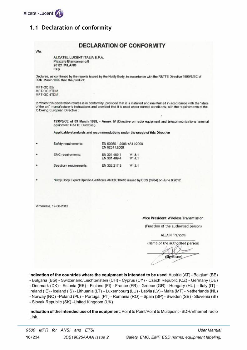
1.1 Declaration of conformity
Indication of the countries where the equipment is intended to be used: Austria (AT) - Belgium (BE)- Bulgaria (BG) - Switzerland/Liechtenstein (CH) - Cyprus (CY) - Czech Republic (CZ) - Germany (DE)- Denmark (DK) - Estonia (EE) - Finland (FI) - France (FR) - Greece (GR) - Hungary (HU) – Italy (IT) -Ireland (IE) - Iceland (IS) - Lithuania (LT) – Luxembourg (LU) - Latvia (LV) - Malta (MT) - Netherlands (NL)- Norway (NO) –Poland (PL) – Portugal (PT) - Romania (RO) – Spain (SP) - Sweden (SE) - Slovenia (SI)- Slovak Republic (SK) -United Kingdom (UK)
Indication of the intended use of the equipment: Point to Point/Point to Multipoint - SDH/Ethernet radioLink.
User Manual
Safety, EMC, EMF, ESD norms, equipment labeling,
9500 MPR for ANSI and ETSI
3DB19025AAAA Issue 216/234
1.2 Applicable standards and recommendations
1999/5/CE of 09 March 1999
Safety requirements: EN 60950-1:2006+A11:2009, EN 62311:2008
EMC requirements: EN 301 489-1 V1.8.1, EN 301 489-4 V1.4.1
Spectrum requirements: EN 302 217-3 V1.3.1
1.3 Safety rules
1.3.1 General rules
Before carrying out any installation, turn-on, tests or operation and maintenance operations, read carefullythe related sections of this Manual, in particular:
– Hardware Installation
– Commissioning
– Maintenance and Upgrade
Observe safety rules
– When equipment is operating nobody is allowed to have access inside on the equipment parts whichare protected with Cover Plate Shields removable with tools.
– In case of absolute need to have access inside, on the equipment parts when it is operating this isallowed exclusively to service personnel, where for Service Personnel or Technical assistance ismeant:
• "personnel which has adequate Technical Knowledge and experience necessary to be awareof the danger that he might find in carrying out an operation and of the necessary measure-ments to reduce danger to minimum for him and for others".
• The Service Personnel can only replace the faulty units with spare parts.
• The Service Personnel is not allowed to repair: hence the access to the parts no specified isnot permitted.
• The keys and/or the tools used to open doors, hinged covers to remove parts which give accessto compartments in which are present high dangerous voltages must belong exclusively to theservice personnel.
– For the eventual cleaning of the external parts of the equipment, absolutely do not use any inflam-mable substance or substances which in some way may alter the markings, inscriptions and so on.
– It is recommended to use a slightly wet cleaning cloth.
The Safety Rules stated in the handbook describe the operations and/or precautions to observe to safe-guard service personnel during the working phases and to guarantee equipment safety, i.e., not exposingpersons, animals, things to the risk of being injured/damaged.
User Manual
Safety, EMC, EMF, ESD norms, equipment labeling,
9500 MPR for ANSI and ETSI
3DB19025AAAA Issue 2 17/234
Whenever the safety protection features have been impaired, REMOVE POWER.
To cut off power proceed to switch off the power supply units as well as cut off power station upstream(rack or station distribution frame).
The safety rules described in this handbook are distinguished by the following symbol and statement:
1.3.2 RF Radiation Safety, Maximum Permissible Exposure Limits
Regarding guidelines for human exposure limits to Radio Frequency (RF) electromagnetic fields, thisAlcatel-Lucent product has been evaluated for compliance with FCC OET Bulletin 65 and human expo-sure limits recommended by the International Commission on Non-Ionizing Radiation Protection(ICNIRP), IEEE, and adopted by ANSI.
All Alcatel-Lucent 80GHz radios utilizing external 1ft or 2ft diameter antennas are below the General Pop-ulation/Uncontrolled Exposure limits of 1 mW/cm2, and well below the Occupational/Controlled Exposurelimit of 5mW/cm2. The maximum near-field power density is substantially less than the Maximum Per-missible Exposure (MPE). The minimum separation distance is 20 cm, even if calculations indicate thatthe MPE distance would be less.
1.3.3 Labels indicating danger, forbiddance, command
It is of utmost importance to follow the instructions printed on the labels affixed to the units and assemblies.
– dangerous electrical voltages
– harmful optical signals
– risk of explosion
– moving mechanical parts
– heat-radiating Mechanical Parts
– microwave radiations
Pay attention to the information stated in the following, and proceed as instructed.
The symbols presented in following paragraphs are all the possible symbols that could be present on Alca-tel-Lucent equipment, but are not all necessarily present on the equipment this handbook refers to.
Note
User Manual
Safety, EMC, EMF, ESD norms, equipment labeling,
9500 MPR for ANSI and ETSI
3DB19025AAAA Issue 218/234
Dangerous electrical voltages
[1] Labeling
The following warning label is affixed next to dangerous voltages (>42.4 Vp; >60 Vdc).
If it is a Class 1 equipment connected to mains, then the label associated to it will state that the equip-ment will have to be grounded before connecting it to the power supply voltage, e.g.:
[2] Safety instructions
DANGER! Possibility of personal injury:
Carefully observe the specific procedures for installation / turn-up and commissioning / maintenanceof equipment parts where D.C. power is present, described in the relevant installation / turn-up andcommissioning / maintenance documents and the following general rules:
• Personal injury can be caused by -48VDC. Avoid touching powered terminals with any exposedpart of your body.
• Short circuiting, low-voltage, low-impedance, DC circuits can cause severe arcing that canresult in burns and/or eye damage. Remove rings, watches, and other metal jewelry beforeworking with primary circuits. Exercise caution to avoid shorting power input terminals.
Risks of Explosions: labeling and safety instructions
This risk is present when batteries are used, and it is signaled by the following label:
Therefore, slits or apertures are made to let air circulate freely and allow dangerous gasses to down flow(battery-emitted hydrogen). A 417-IEC-5641 Norm. compliant label is affixed next to it indicating that theopenings must not be covered up.
User Manual
Safety, EMC, EMF, ESD norms, equipment labeling,
9500 MPR for ANSI and ETSI
3DB19025AAAA Issue 2 19/234
Moving Mechanical Parts: labeling and safety instructions
The following warning label is affixed next to fans or other moving mechanical parts:
Before carrying out any maintenance operation see that all the moving mechanical parts have beenstopped.
Equipment connection to earth
Terminals for equipment connection to earth, to be done according to international safety standards, arepointed out by the suitable symbol:
The position of earth connection terminals is specified in the Hardware Installation section.
Heat-radiating Mechanical Parts: labeling and safety instructions
The presence of heat-radiating mechanical parts is indicated by the following warning label in compliancywith IEC 417 Norm, Fig.5041:
DANGER! Possibility of personal injury:
Carefully observe the specific procedures for installation / turn-up and commissioning / maintenance ofequipment parts where heat-radiating mechanical parts are present, described in the relevant installation/ turn-up and commissioning / maintenance documents and the following general rule:
Personal injury can be caused by heat. Avoid touching powered terminals with any exposed part of yourbody.
User Manual
Safety, EMC, EMF, ESD norms, equipment labeling,
9500 MPR for ANSI and ETSI
3DB19025AAAA Issue 220/234

Optical safety
The equipment contains Class 1 laser component according to IEC 60825-1 (par. 5).
The laser source is placed in the optional SFP plug-in, which has to be installed in the MPT-GC. The lasersource is placed in the left side of the SFP plug-in.
According to the IEC 60825-1 the explanatory label is not attached to the equipment due to the lack ofspace.
CLASS 1 LASER PRODUCT
User Manual
Safety, EMC, EMF, ESD norms, equipment labeling,
9500 MPR for ANSI and ETSI
3DB19025AAAA Issue 2 21/234
Microwave radiations (EMF norms)
Equipment emitting RF power (Reminder from site preparation procedure):
The site must be compliant with ICNIRP guidelines or local regulation if more restrictive.
The following rules should be strictly applied by Customer:
– Non authorized persons should not enter the compliance boundaries, if any, for the general public.
– Compliance RF boundaries, if any, related to Electro Magnetic Field exposure must be marked.
– Workers should be allowed to switch-off the power if they have to operate inside compliance bound-aries.
– Assure good cable connection.
– Install the antenna as high as possible from floor or area with public access (if possible the cylinderdelimiting the compliance boundaries, if any, or the cylinder corresponding to the transmission areadirectly in front of antenna with the same diameter as the antenna, more than 2 meters high).
– Install the antenna as far as possible from other existing equipment emitting RF power.
Anyway remind that someone standing in front of the 9500 MPR antenna may cause traffic shutdown.
Place the relevant stickers:
On the site when applicable (when people can cross the compliance boundaries and/or the transmissionarea of the antenna, i.e. roof top installation)
– Warning label "Do not stand on the antenna axis"
On the mast (front side)
– EMF emission warning sign (Yellow and black) to be placed at bottom of antenna, visible by someonemoving in front of the antenna (roof top installation)
On the antenna (rear side)
– EMF emission warning sign, placed on the antenna.
EMF emission warning sign
User Manual
Safety, EMC, EMF, ESD norms, equipment labeling,
9500 MPR for ANSI and ETSI
3DB19025AAAA Issue 222/234
1.4 Electromagnetic compatibility (EMC norms)
The equipment's EMC norms depend on the type of installation being carried out (cable termination,grounding etc.,) and on the operating conditions (equipment, setting options of the electrical/electronicunits, presence of dummy covers, etc.).
Before carrying out any installation, turn-on, tests & operation and maintenance operations, read carefullythe related sections of this Manual, in particular:
– Hardware Installation
– Maintenance and Upgrade
The norms set down to guarantee EMC compatibility, are distinguished inside this Manual by the symboland term:
[1] EMC General Norms - Installation
• All connections (towards the external source of the equipment) made with shielded cables useonly cables and connectors suggested in this Manual or in the relevant Plant Documentation,or those specified in the Customer's "Installation Norms" (or similar documents)
• Shielded cables must be suitably terminated
• Install filters outside the equipment as required
• Ground connect the equipment utilizing a conductor with proper diameter and impedance
• Mount shields (if utilized), previously positioned during the installation phase, but not beforehaving cleaned and degrease it
• Before inserting the shielded unit proceed to clean and degrease all peripheral surfaces (con-tact springs and connection points, etc.)
• Screw fasten the units to the subrack
• To correctly install EMC compatible equipment follow the instructions given
[2] EMC General Norms - Turn-on, Tests & Operation
• Preset the electrical units as required to guarantee EMC compatibility
• Check that the equipment is operating with all the shields properly positioned (dummy covers,ESD connector protections, etc.)
• To properly use EMC compatible equipment observe the information given
[3] EMC General Norms - Maintenance
• Before inserting the shielded unit, which will replace the faulty or modified unit, proceed to cleanand degrease all peripheral surfaces (contact springs and connection points, etc.)
• Clean the dummy covers of the spare units as well
• Screw fasten the units to the subrack.
EMC Norms
User Manual
Safety, EMC, EMF, ESD norms, equipment labeling,
9500 MPR for ANSI and ETSI
3DB19025AAAA Issue 2 23/234
1.5 Equipment protection against electrostatic discharges
Before removing the ESD protections from the monitors, connectors etc., observe the precautionary mea-sures stated. Make sure that the ESD protections have been replaced and after having terminated themaintenance and monitoring operations.
Most electronic devices are sensitive to electrostatic discharges, to this concern the following warninglabels have been affixed:
Observe the precautionary measures stated when having to touch the electronic parts during the instal-lation/maintenance phases.
Workers are supplied with anti static protection devices consisting of:
– an elasticized band worn around the wrist – a coiled cord connected to the elasticized band and to the stud on the subrack
1.6 Cautions to avoid equipment damage
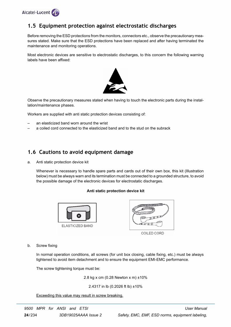
a. Anti static protection device kit
Whenever is necessary to handle spare parts and cards out of their own box, this kit (Illustrationbelow) must be always warn and its termination must be connected to a grounded structure, to avoidthe possible damage of the electronic devices for electrostatic discharges.
Anti static protection device kit
b. Screw fixing
In normal operation conditions, all screws (for unit box closing, cable fixing, etc.) must be alwaystightened to avoid item detachment and to ensure the equipment EMI-EMC performance.
The screw tightening torque must be:
2.8 kg x cm (0.28 Newton x m) ±10%
2.4317 in lb (0.2026 ft lb) ±10%
Exceeding this value may result in screw breaking.
User Manual
Safety, EMC, EMF, ESD norms, equipment labeling,
9500 MPR for ANSI and ETSI
3DB19025AAAA Issue 224/234
1.7 RoHS directive
This Alcatel-Lucent product has been certified to be in compliance with the RoHS (Restrictions of Haz-ardous Substances) Directive 2002/95/EC. The implementation of this directive requirement is intendedto reduce the risks to human health and the environment by a reduction in the use of hazardous sub-stances.
1.8 WEEE compliance
Alcatel-Lucent is fully compliant with the Waste Electrical and Electronic Equipment (WEEE) directive andimplementing regulations within the European Union.
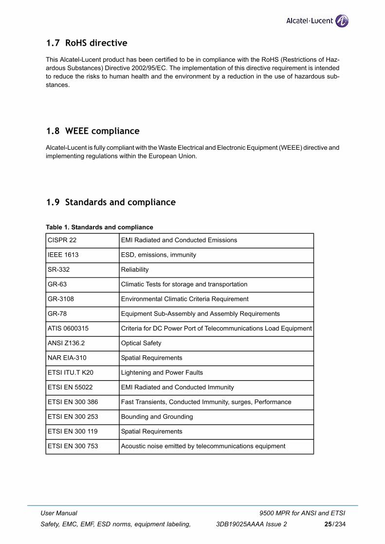
1.9 Standards and compliance
Table 1. Standards and compliance
CISPR 22 EMI Radiated and Conducted Emissions
IEEE 1613 ESD, emissions, immunity
SR-332 Reliability
GR-63 Climatic Tests for storage and transportation
GR-3108 Environmental Climatic Criteria Requirement
GR-78 Equipment Sub-Assembly and Assembly Requirements
ATIS 0600315 Criteria for DC Power Port of Telecommunications Load Equipment
ANSI Z136.2 Optical Safety
NAR EIA-310 Spatial Requirements
ETSI ITU.T K20 Lightening and Power Faults
ETSI EN 55022 EMI Radiated and Conducted Immunity
ETSI EN 300 386 Fast Transients, Conducted Immunity, surges, Performance
ETSI EN 300 253 Bounding and Grounding
ETSI EN 300 119 Spatial Requirements
ETSI EN 300 753 Acoustic noise emitted by telecommunications equipment
User Manual
Safety, EMC, EMF, ESD norms, equipment labeling,
9500 MPR for ANSI and ETSI
3DB19025AAAA Issue 2 25/234

User Manual
Safety, EMC, EMF, ESD norms, equipment labeling,
9500 MPR for ANSI and ETSI
3DB19025AAAA Issue 226/234
2 OverviewAn Alcatel-Lucent MPT-GC link consists of two radio terminals that transmit to each other on a full-duplexchannel pair, providing point-to-point Ethernet and/or SONET/SDH connectivity between two locations.
Alcatel-Lucent radios are Frequency Division Duplex (FDD), transmitting on one of many possible fre-quencies and receiving on the duplex of the frequency pair at the same time. Channel tuning is in accor-dance with ECC REC /(05/07).
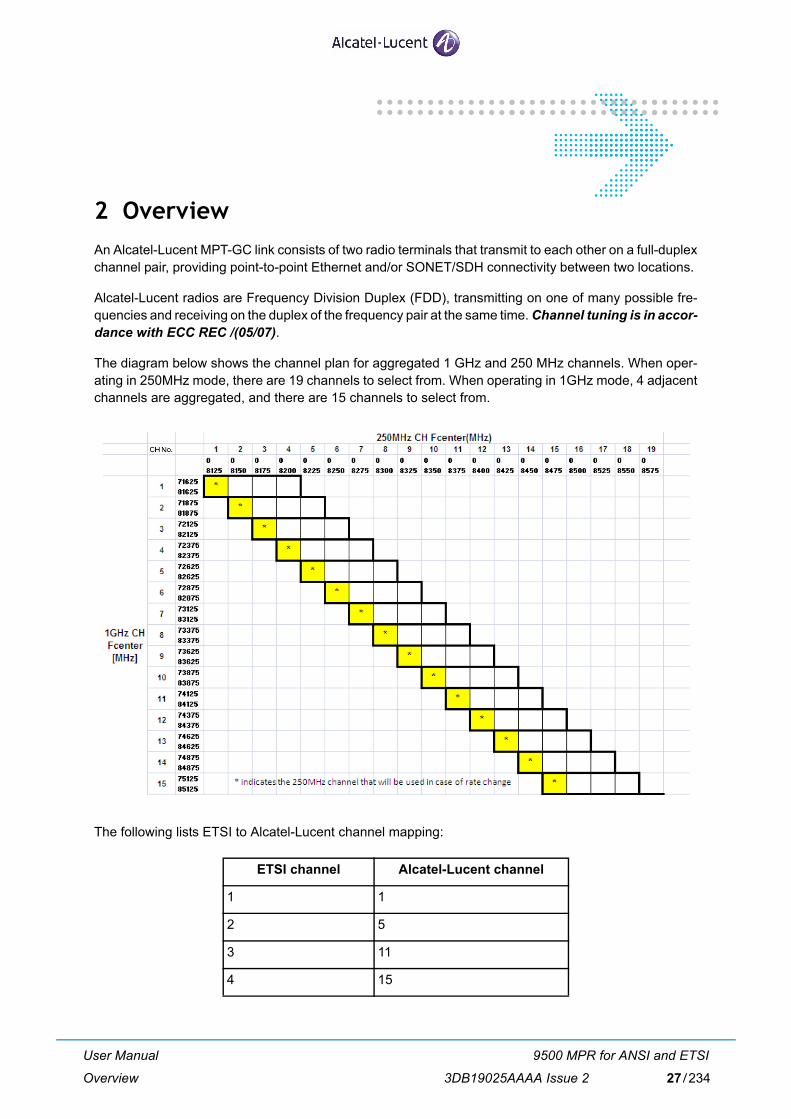
The diagram below shows the channel plan for aggregated 1 GHz and 250 MHz channels. When oper-ating in 250MHz mode, there are 19 channels to select from. When operating in 1GHz mode, 4 adjacentchannels are aggregated, and there are 15 channels to select from.
The following lists ETSI to Alcatel-Lucent channel mapping:
ETSI channel Alcatel-Lucent channel
1 1
2 5
3 11
4 15
User Manual
Overview
9500 MPR for ANSI and ETSI
3DB19025AAAA Issue 2 27/234
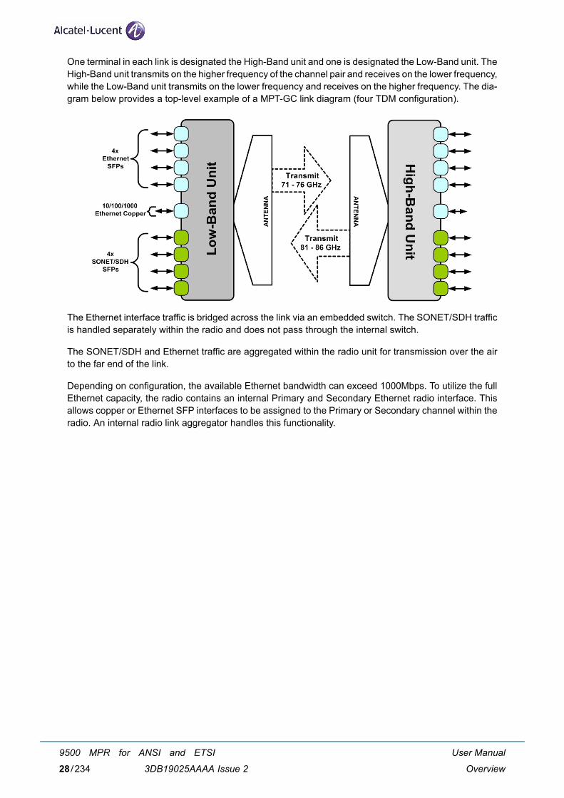
One terminal in each link is designated the High-Band unit and one is designated the Low-Band unit. TheHigh-Band unit transmits on the higher frequency of the channel pair and receives on the lower frequency,while the Low-Band unit transmits on the lower frequency and receives on the higher frequency. The dia-gram below provides a top-level example of a MPT-GC link diagram (four TDM configuration).
The Ethernet interface traffic is bridged across the link via an embedded switch. The SONET/SDH trafficis handled separately within the radio and does not pass through the internal switch.
The SONET/SDH and Ethernet traffic are aggregated within the radio unit for transmission over the airto the far end of the link.
Depending on configuration, the available Ethernet bandwidth can exceed 1000Mbps. To utilize the fullEthernet capacity, the radio contains an internal Primary and Secondary Ethernet radio interface. Thisallows copper or Ethernet SFP interfaces to be assigned to the Primary or Secondary channel within theradio. An internal radio link aggregator handles this functionality.
User Manual
Overview
9500 MPR for ANSI and ETSI
3DB19025AAAA Issue 228/234
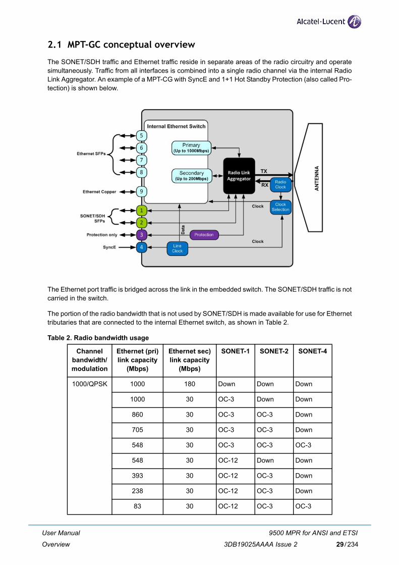
2.1 MPT-GC conceptual overview
The SONET/SDH traffic and Ethernet traffic reside in separate areas of the radio circuitry and operatesimultaneously. Traffic from all interfaces is combined into a single radio channel via the internal RadioLink Aggregator. An example of a MPT-CG with SyncE and 1+1 Hot Standby Protection (also called Pro-tection) is shown below.
The Ethernet port traffic is bridged across the link in the embedded switch. The SONET/SDH traffic is notcarried in the switch.
The portion of the radio bandwidth that is not used by SONET/SDH is made available for use for Ethernettributaries that are connected to the internal Ethernet switch, as shown in Table 2.
Table 2. Radio bandwidth usage
Channel bandwidth/modulation
Ethernet (pri) link capacity
(Mbps)
Ethernet sec) link capacity
(Mbps)
SONET-1 SONET-2 SONET-4
1000/QPSK 1000 180 Down Down Down
1000 30 OC-3 Down Down
860 30 OC-3 OC-3 Down
705 30 OC-3 OC-3 Down
548 30 OC-3 OC-3 OC-3
548 30 OC-12 Down Down
393 30 OC-12 OC-3 Down
238 30 OC-12 OC-3 Down
83 30 OC-12 OC-3 OC-3
User Manual
Overview
9500 MPR for ANSI and ETSI
3DB19025AAAA Issue 2 29/234
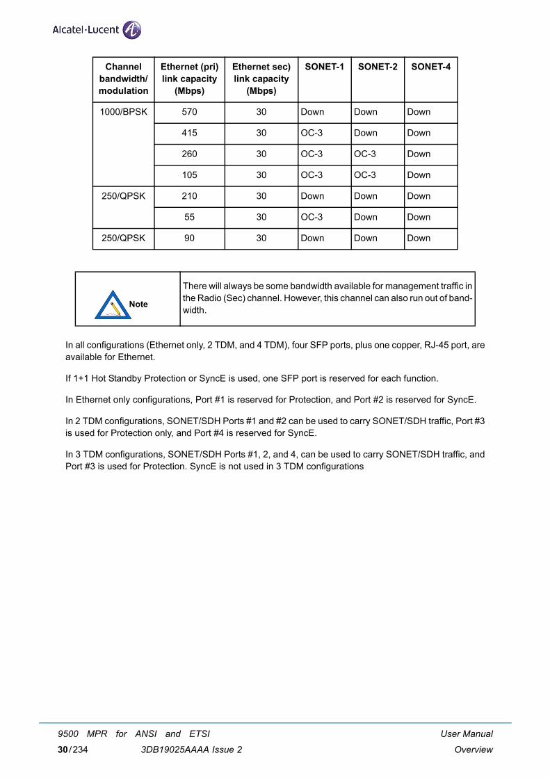
In all configurations (Ethernet only, 2 TDM, and 4 TDM), four SFP ports, plus one copper, RJ-45 port, areavailable for Ethernet.
If 1+1 Hot Standby Protection or SyncE is used, one SFP port is reserved for each function.
In Ethernet only configurations, Port #1 is reserved for Protection, and Port #2 is reserved for SyncE.
In 2 TDM configurations, SONET/SDH Ports #1 and #2 can be used to carry SONET/SDH traffic, Port #3is used for Protection only, and Port #4 is reserved for SyncE.
In 3 TDM configurations, SONET/SDH Ports #1, 2, and 4, can be used to carry SONET/SDH traffic, andPort #3 is used for Protection. SyncE is not used in 3 TDM configurations
1000/BPSK 570 30 Down Down Down
415 30 OC-3 Down Down
260 30 OC-3 OC-3 Down
105 30 OC-3 OC-3 Down
250/QPSK 210 30 Down Down Down
55 30 OC-3 Down Down
250/QPSK 90 30 Down Down Down
There will always be some bandwidth available for management traffic inthe Radio (Sec) channel. However, this channel can also run out of band-width.
Channel bandwidth/modulation
Ethernet (pri) link capacity
(Mbps)
Ethernet sec) link capacity
(Mbps)
SONET-1 SONET-2 SONET-4
User Manual
Overview
9500 MPR for ANSI and ETSI
3DB19025AAAA Issue 230/234
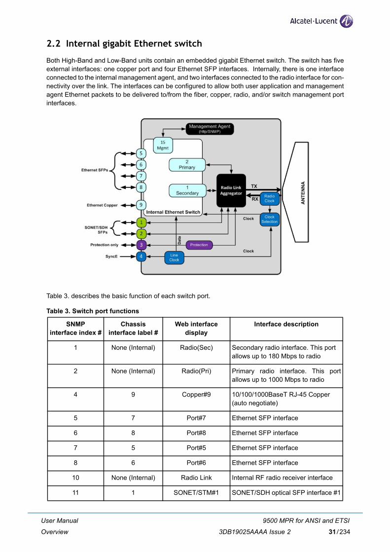
2.2 Internal gigabit Ethernet switch
Both High-Band and Low-Band units contain an embedded gigabit Ethernet switch. The switch has fiveexternal interfaces: one copper port and four Ethernet SFP interfaces. Internally, there is one interfaceconnected to the internal management agent, and two interfaces connected to the radio interface for con-nectivity over the link. The interfaces can be configured to allow both user application and managementagent Ethernet packets to be delivered to/from the fiber, copper, radio, and/or switch management portinterfaces.
Table 3. describes the basic function of each switch port.
Table 3. Switch port functions
SNMP interface index #
Chassis interface label #
Web interface display
Interface description
1 None (Internal) Radio(Sec) Secondary radio interface. This portallows up to 180 Mbps to radio
2 None (Internal) Radio(Pri) Primary radio interface. This portallows up to 1000 Mbps to radio
4 9 Copper#9 10/100/1000BaseT RJ-45 Copper(auto negotiate)
5 7 Port#7 Ethernet SFP interface
6 8 Port#8 Ethernet SFP interface
7 5 Port#5 Ethernet SFP interface
8 6 Port#6 Ethernet SFP interface
10 None (Internal) Radio Link Internal RF radio receiver interface
11 1 SONET/STM#1 SONET/SDH optical SFP interface #1
User Manual
Overview
9500 MPR for ANSI and ETSI
3DB19025AAAA Issue 2 31/234
2.3 MPT-GC connections
The MPT-GC can be connected to an indoor GEthernet Generic Device having the pre-requisites listedin paragraph 2.3.1.
As GEthernet Generic Device can be used an MSS-4/MSS-8.
For interconnection refer to paragraph 6.6 on page 141.
2.3.1 GEthernet generic device pre-requisites
One GE traffic port:
– optical
For local management option:
– A FE (minimum) port
– VLAN management capability to create a tagged service between local management port and MPTGEthernet port.One service open with VLAN ID on GE Port.
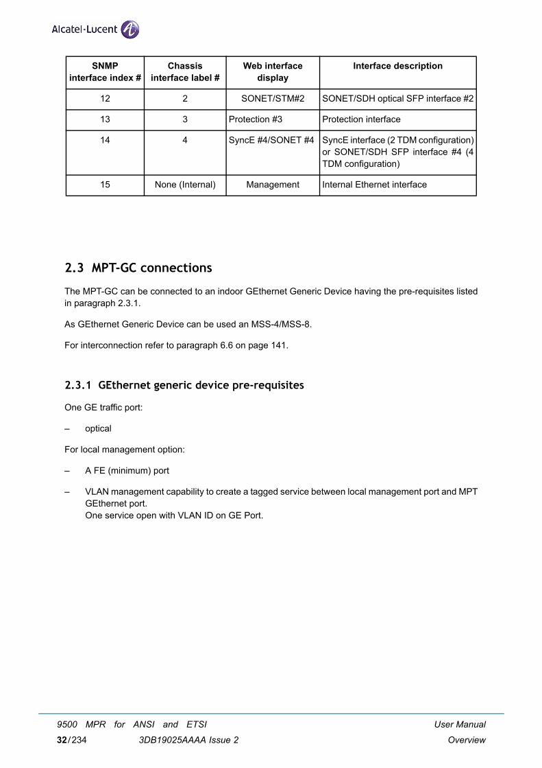
12 2 SONET/STM#2 SONET/SDH optical SFP interface #2
13 3 Protection #3 Protection interface
14 4 SyncE #4/SONET #4 SyncE interface (2 TDM configuration)or SONET/SDH SFP interface #4 (4TDM configuration)
15 None (Internal) Management Internal Ethernet interface
SNMP interface index #
Chassis interface label #
Web interface display
Interface description
User Manual
Overview
9500 MPR for ANSI and ETSI
3DB19025AAAA Issue 232/234
2.4 VLAN connections
The MPT-GC radio allows each Ethernet interface to be assigned to internal VLAN IDs within the rangeof 2 to 4080. This allows a great deal of flexibility in how the interfaces are connected to, or separated from,each other within the MPT-GC's internal switch.
The management access can use untagged (default) or tagged.
Tagged management access allows for management traffic to be carried outside of the MPT-GC radio intothe network on a VLAN.
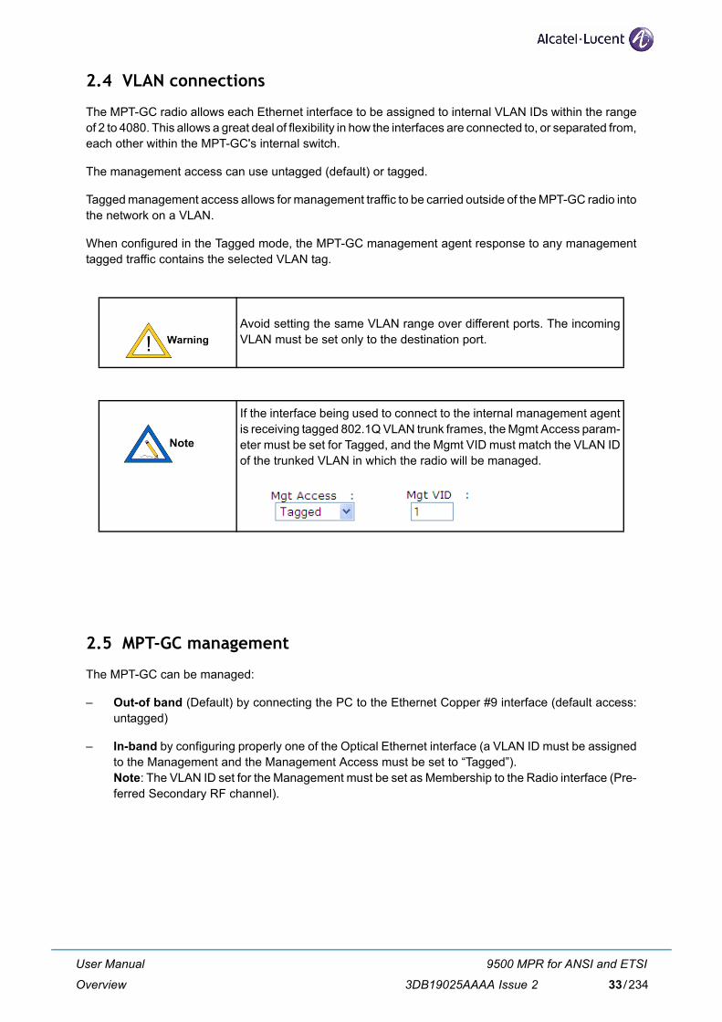
When configured in the Tagged mode, the MPT-GC management agent response to any managementtagged traffic contains the selected VLAN tag.
2.5 MPT-GC management
The MPT-GC can be managed:
– Out-of band (Default) by connecting the PC to the Ethernet Copper #9 interface (default access:untagged)
– In-band by configuring properly one of the Optical Ethernet interface (a VLAN ID must be assignedto the Management and the Management Access must be set to “Tagged”).Note: The VLAN ID set for the Management must be set as Membership to the Radio interface (Pre-ferred Secondary RF channel).
Avoid setting the same VLAN range over different ports. The incomingVLAN must be set only to the destination port.
If the interface being used to connect to the internal management agentis receiving tagged 802.1Q VLAN trunk frames, the Mgmt Access param-eter must be set for Tagged, and the Mgmt VID must match the VLAN IDof the trunked VLAN in which the radio will be managed.
User Manual
Overview
9500 MPR for ANSI and ETSI
3DB19025AAAA Issue 2 33/234
2.6 SONET/SDH data traffic
The MPT-GC radio will carry up to four interfaces worth of SONET/SDH traffic, with the option to individ-ually configure each interface for either OC-3 (STM-1) or OC-12 (STM-4).
A payload of one OC-3 (STM-1) plus one OC-12 (STM-4) can be carried in MPT-GC, while still leaving370 Mbps (primary) and 30 Mbps (secondary) of bandwidth available for Ethernet traffic.
MPT-GC extracts the timing reference individually from the ingress data signal applied to the SONET/SDHinterface and delivers the same timing at the far-end egress of the SONET/SDH data signal.
MPT-GC does not monitor any of the SONET/SDH overhead information.
2.7 AES encryption feature
2.7.1 Introduction
The Advanced Encryption Standard (AES) feature provides a method for securing the data traffic travelingacross the radio link by encrypting the information.
The AES feature, and the associated procedures in this section, are applicable to MPT-GC systems mod-els, -E and -3TDM. These systems are available as factory-configured or field-upgrade to AES.
In cryptography, AES is a block cipher adopted as an encryption standard by the U.S. government. AESis one of the most popular algorithms used in symmetric key cryptography. The design and strength ofall key lengths of the AES algorithm (i.e., 128, 192 and 256) are sufficient to protect classified informationup to the SECRET level. TOP SECRET information requires use of either the 192 or 256 key lengths. TheAlcatel-Lucent AES solution uses the 256 key length.
For the 256 Key, 64, 4-bit HEX characters or 32, 8-bit ASCII keyboard text characters are used for the key.
When upgrading the system with the STM-4 license file, please be awarethat a new FPGA version is required.
The unit clocks data into the SONET/SDH interface, based on the exter-nal clock being received from the connected equipment. Therefore, whenthe SONET/SDH port is configured for OC-12/STM-4, the interface willstill clock an OC-3/STM-1 signal over the link transparently, if connected.
The keys are manually entered and do not change.
User Manual
Overview
9500 MPR for ANSI and ETSI
3DB19025AAAA Issue 234/234
By default, the AES capable units that are factory configured or upgraded have a matching default keyactive on both ends of the link.
The Link Quality voltage reading, which is used to determine the performance of the link, is fully functional,independent of AES configuration.
2.7.2 AES upgrade procedure
Upgrading your radio to AES involves obtaining an AES license and firmware from Alcatel-Lucent.
Use the following steps to upgrade your radio to include AES.
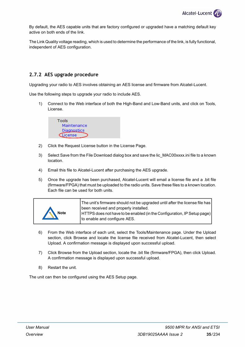
1) Connect to the Web interface of both the High-Band and Low-Band units, and click on Tools,License.
2) Click the Request License button in the License Page.
3) Select Save from the File Download dialog box and save the lic_MAC00xxxx.ini file to a knownlocation.
4) Email this file to Alcatel-Lucent after purchasing the AES upgrade.
5) Once the upgrade has been purchased, Alcatel-Lucent will email a license file and a .bit file(firmware/FPGA) that must be uploaded to the radio units. Save these files to a known location.Each file can be used for both units.
6) From the Web interface of each unit, select the Tools/Maintenance page. Under the Uploadsection, click Browse and locate the license file received from Alcatel-Lucent, then selectUpload. A confirmation message is displayed upon successful upload.
7) Click Browse from the Upload section, locate the .bit file (firmware/FPGA), then click Upload.A confirmation message is displayed upon successful upload.
8) Restart the unit.
The unit can then be configured using the AES Setup page.
The unit’s firmware should not be upgraded until after the license file hasbeen received and properly installed. HTTPS does not have to be enabled (in the Configuration, IP Setup page)to enable and configure AES.
User Manual
Overview
9500 MPR for ANSI and ETSI
3DB19025AAAA Issue 2 35/234
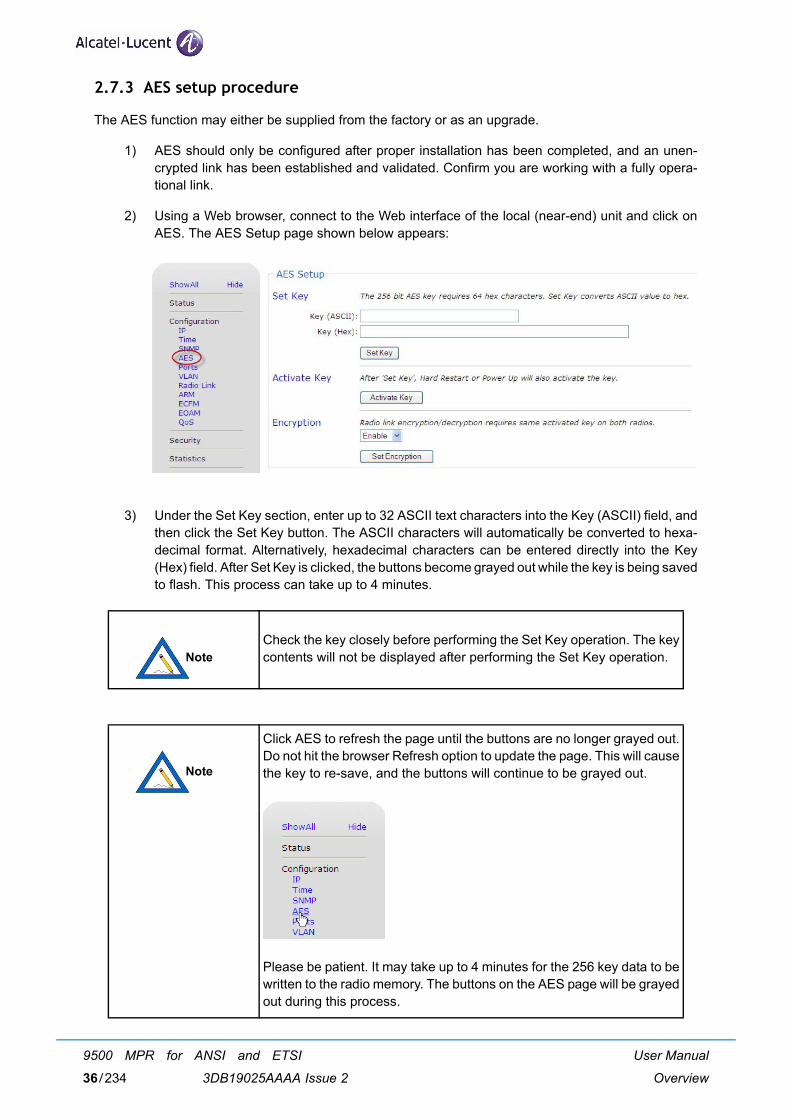
2.7.3 AES setup procedure
The AES function may either be supplied from the factory or as an upgrade.
1) AES should only be configured after proper installation has been completed, and an unen-crypted link has been established and validated. Confirm you are working with a fully opera-tional link.
2) Using a Web browser, connect to the Web interface of the local (near-end) unit and click onAES. The AES Setup page shown below appears:
3) Under the Set Key section, enter up to 32 ASCII text characters into the Key (ASCII) field, andthen click the Set Key button. The ASCII characters will automatically be converted to hexa-decimal format. Alternatively, hexadecimal characters can be entered directly into the Key(Hex) field. After Set Key is clicked, the buttons become grayed out while the key is being savedto flash. This process can take up to 4 minutes.
Check the key closely before performing the Set Key operation. The keycontents will not be displayed after performing the Set Key operation.
Click AES to refresh the page until the buttons are no longer grayed out.Do not hit the browser Refresh option to update the page. This will causethe key to re-save, and the buttons will continue to be grayed out.
Please be patient. It may take up to 4 minutes for the 256 key data to bewritten to the radio memory. The buttons on the AES page will be grayedout during this process.
User Manual
Overview
9500 MPR for ANSI and ETSI
3DB19025AAAA Issue 236/234
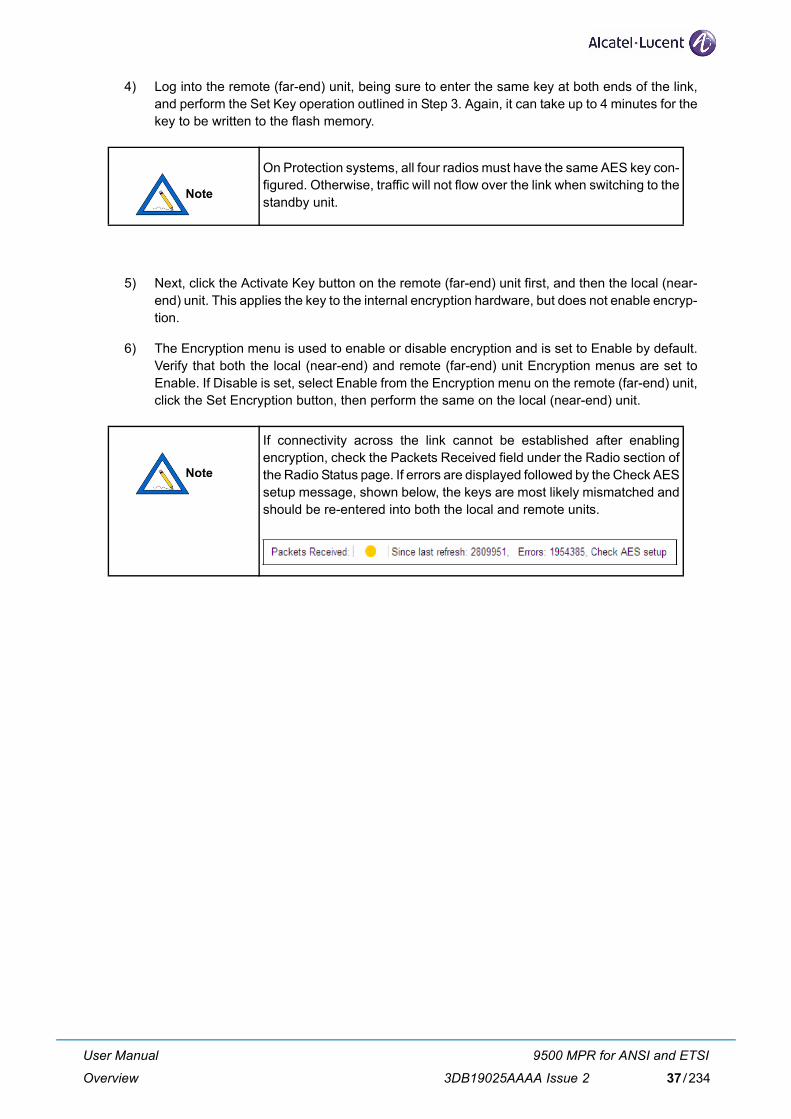
4) Log into the remote (far-end) unit, being sure to enter the same key at both ends of the link,and perform the Set Key operation outlined in Step 3. Again, it can take up to 4 minutes for thekey to be written to the flash memory.
5) Next, click the Activate Key button on the remote (far-end) unit first, and then the local (near-end) unit. This applies the key to the internal encryption hardware, but does not enable encryp-tion.
6) The Encryption menu is used to enable or disable encryption and is set to Enable by default.Verify that both the local (near-end) and remote (far-end) unit Encryption menus are set toEnable. If Disable is set, select Enable from the Encryption menu on the remote (far-end) unit,click the Set Encryption button, then perform the same on the local (near-end) unit.
On Protection systems, all four radios must have the same AES key con-figured. Otherwise, traffic will not flow over the link when switching to thestandby unit.
If connectivity across the link cannot be established after enablingencryption, check the Packets Received field under the Radio section ofthe Radio Status page. If errors are displayed followed by the Check AESsetup message, shown below, the keys are most likely mismatched andshould be re-entered into both the local and remote units.
User Manual
Overview
9500 MPR for ANSI and ETSI
3DB19025AAAA Issue 2 37/234
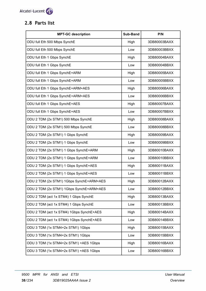
2.8 Parts list
MPT-GC description Sub-Band P/N
ODU full Eth 500 Mbps SynchE High 3DB80003BAXX
ODU full Eth 500 Mbps SynchE Low 3DB80003BBXX
ODU full Eth 1 Gbps SynchE High 3DB80004BAXX
ODU full Eth 1 Gbps SynchE Low 3DB80004BBXX
ODU full Eth 1 Gbps SynchE+ARM High 3DB80005BAXX
ODU full Eth 1 Gbps SynchE+ARM Low 3DB80005BBXX
ODU full Eth 1 Gbps SynchE+ARM+AES High 3DB80006BAXX
ODU full Eth 1 Gbps SynchE+ARM+AES Low 3DB80006BBXX
ODU full Eth 1 Gbps SynchE+AES High 3DB80007BAXX
ODU full Eth 1 Gbps SynchE+AES Low 3DB80007BBXX
ODU 2 TDM (2x STM1) 500 Mbps SynchE High 3DB80008BAXX
ODU 2 TDM (2x STM1) 500 Mbps SynchE Low 3DB80008BBXX
ODU 2 TDM (2x STM1) 1 Gbps SynchE High 3DB80009BAXX
ODU 2 TDM (2x STM1) 1 Gbps SynchE Low 3DB80009BBXX
ODU 2 TDM (2x STM1) 1 Gbps SynchE+ARM High 3DB80010BAXX
ODU 2 TDM (2x STM1) 1 Gbps SynchE+ARM Low 3DB80010BBXX
ODU 2 TDM (2x STM1) 1 Gbps SynchE+AES High 3DB80011BAXX
ODU 2 TDM (2x STM1) 1 Gbps SynchE+AES Low 3DB80011BBXX
ODU 2 TDM (2x STM1) 1Gbps SynchE+ARM+AES High 3DB80012BAXX
ODU 2 TDM (2x STM1) 1Gbps SynchE+ARM+AES Low 3DB80012BBXX
ODU 2 TDM (act 1x STM4) 1 Gbps SynchE High 3DB80013BAXX
ODU 2 TDM (act 1x STM4) 1 Gbps SynchE Low 3DB80013BBXX
ODU 2 TDM (act 1x STM4) 1Gbps SynchE+AES High 3DB80014BAXX
ODU 2 TDM (act 1x STM4) 1Gbps SynchE+AES Low 3DB80014BBXX
ODU 3 TDM (1x STM4+2x STM1) 1Gbps High 3DB80015BAXX
ODU 3 TDM (1x STM4+2x STM1) 1Gbps Low 3DB80015BBXX
ODU 3 TDM (1x STM4+2x STM1) +AES 1Gbps High 3DB80016BAXX
ODU 3 TDM (1x STM4+2x STM1) +AES 1Gbps Low 3DB80016BBXX
User Manual
Overview
9500 MPR for ANSI and ETSI
3DB19025AAAA Issue 238/234
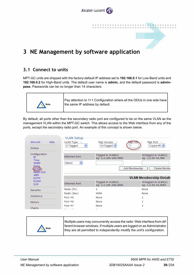
3 NE Management by software application
3.1 Connect to units
MPT-GC units are shipped with the factory-default IP address set to 192.168.0.1 for Low-Band units and192.168.0.2 for High-Band units. The default user name is admin, and the default password is admin-pass. Passwords can be no longer than 14 characters.
By default, all ports other than the secondary radio port are configured to be on the same VLAN as themanagement VLAN within the MPT-GC switch. This allows access to the Web interface from any of theports, except the secondary radio port. An example of this concept is shown below.
Pay attention to 1+1 Configuration where all the ODUs in one side havethe same IP address by default.
Multiple users may concurrently access the radio Web interface from dif-ferent browser windows. If multiple users are logged on as Administrator,they are all permitted to independently modify the unit's configuration.
User Manual
NE Management by software application
9500 MPR for ANSI and ETSI
3DB19025AAAA Issue 2 39/234
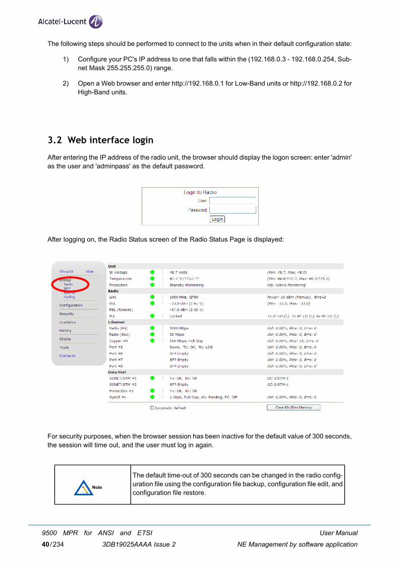
The following steps should be performed to connect to the units when in their default configuration state:
1) Configure your PC's IP address to one that falls within the (192.168.0.3 - 192.168.0.254, Sub-net Mask 255.255.255.0) range.
2) Open a Web browser and enter http://192.168.0.1 for Low-Band units or http://192.168.0.2 forHigh-Band units.
3.2 Web interface login
After entering the IP address of the radio unit, the browser should display the logon screen: enter 'admin'as the user and 'adminpass' as the default password.
After logging on, the Radio Status screen of the Radio Status Page is displayed:
For security purposes, when the browser session has been inactive for the default value of 300 seconds,the session will time out, and the user must log in again.
The default time-out of 300 seconds can be changed in the radio config-uration file using the configuration file backup, configuration file edit, andconfiguration file restore.
User Manual
NE Management by software application
9500 MPR for ANSI and ETSI
3DB19025AAAA Issue 240/234
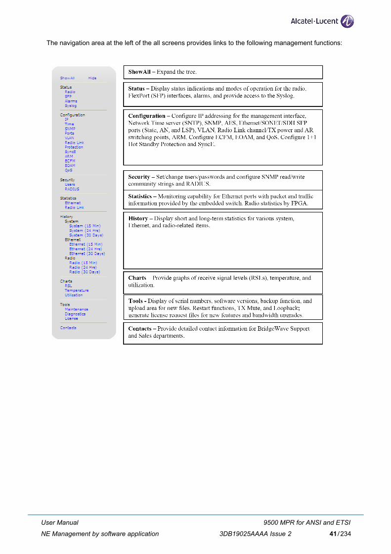
The navigation area at the left of the all screens provides links to the following management functions:
User Manual
NE Management by software application
9500 MPR for ANSI and ETSI
3DB19025AAAA Issue 2 41/234

3.3 Status menu
The status of a link can be determined by viewing the information contained on the pages of the unit's Webinterface.
The top area of every page shows basic unit information about the unit:
RSL(dBm): Indication of Receive Signal Levels in dBm for Local/Remote units.
Link Rate: Maximum available data rate, shared by SONET/SDH and Ethernet payloads.
Uptime: Elapsed time since last unit power cycle or restart.
Temp: Temperature of the millimeter wave circuitry in the Front End Head (FEH).
Transmitter: Indicates the frequency band (High or Low) of the radio's transmitter, and transmit andreceive channel number. A link consists of one Low-Band and one High-Band radio.
Serial: Indicates the serial number and link ID of the radio.
User: Displays the currently logged-in user name. Click Logout to log out.
IP: Network IP address of the Web interface.
MAC: Displays the MAC address of the management NMS and the Protection status of the radio (activeor standby). If Protection is disabled, no Protection status appears.
3.3.1 Radio status
The Radio Status page provides a variety of parameters that display green, yellow, or red indications.
These indicators provide a quick visual summary of the unit's operating condition. Under normal operatingconditions, all indicators should be green.
Red indicators signify unit failures, unconnected network interfaces, or abnormal operating conditions.
Yellow indicators signify marginal operating conditions, which may impact unit operation.
The displayed information is updated every 10 seconds if the Automatic Refresh option is checked.
However, not all values are updated in real time and may take several seconds to reflect the unit's trueoperating status.
An example of the Status page is shown below, and a definition of each parameter follows.
User Manual
NE Management by software application
9500 MPR for ANSI and ETSI
3DB19025AAAA Issue 242/234
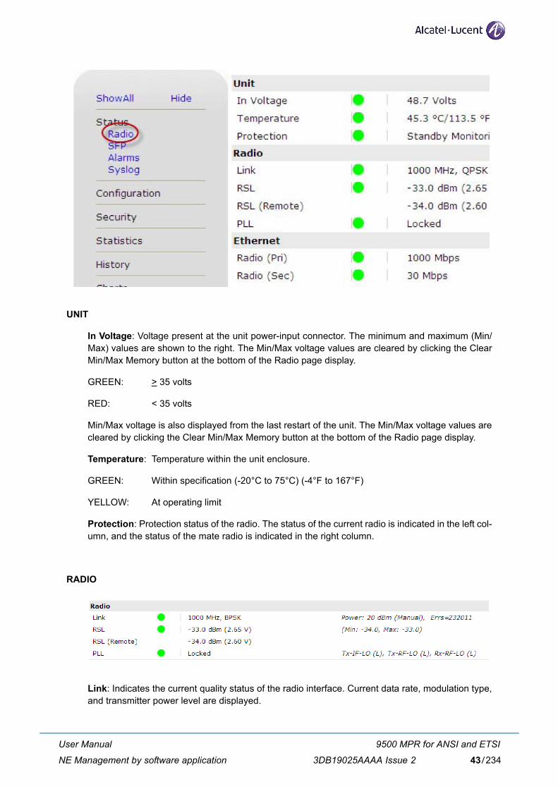
UNIT
In Voltage: Voltage present at the unit power-input connector. The minimum and maximum (Min/Max) values are shown to the right. The Min/Max voltage values are cleared by clicking the ClearMin/Max Memory button at the bottom of the Radio page display.
GREEN: > 35 volts
RED: < 35 volts
Min/Max voltage is also displayed from the last restart of the unit. The Min/Max voltage values arecleared by clicking the Clear Min/Max Memory button at the bottom of the Radio page display.
Temperature: Temperature within the unit enclosure.
GREEN: Within specification (-20°C to 75°C) (-4°F to 167°F)
YELLOW: At operating limit
Protection: Protection status of the radio. The status of the current radio is indicated in the left col-umn, and the status of the mate radio is indicated in the right column.
RADIO
Link: Indicates the current quality status of the radio interface. Current data rate, modulation type,and transmitter power level are displayed.
User Manual
NE Management by software application
9500 MPR for ANSI and ETSI
3DB19025AAAA Issue 2 43/234
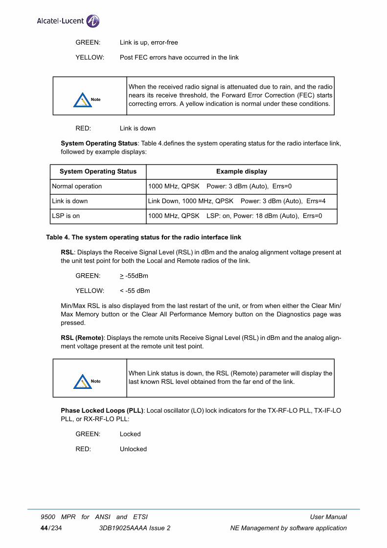
GREEN: Link is up, error-free
YELLOW: Post FEC errors have occurred in the link
RED: Link is down
System Operating Status: Table 4.defines the system operating status for the radio interface link,followed by example displays:
Table 4. The system operating status for the radio interface link
RSL: Displays the Receive Signal Level (RSL) in dBm and the analog alignment voltage present atthe unit test point for both the Local and Remote radios of the link.
GREEN: > -55dBm
YELLOW: < -55 dBm
Min/Max RSL is also displayed from the last restart of the unit, or from when either the Clear Min/Max Memory button or the Clear All Performance Memory button on the Diagnostics page waspressed.
RSL (Remote): Displays the remote units Receive Signal Level (RSL) in dBm and the analog align-ment voltage present at the remote unit test point.
Phase Locked Loops (PLL): Local oscillator (LO) lock indicators for the TX-RF-LO PLL, TX-IF-LOPLL, or RX-RF-LO PLL:
GREEN: Locked
RED: Unlocked
When the received radio signal is attenuated due to rain, and the radionears its receive threshold, the Forward Error Correction (FEC) startscorrecting errors. A yellow indication is normal under these conditions.
System Operating Status Example display
Normal operation 1000 MHz, QPSK Power: 3 dBm (Auto), Errs=0
Link is down Link Down, 1000 MHz, QPSK Power: 3 dBm (Auto), Errs=4
LSP is on 1000 MHz, QPSK LSP: on, Power: 18 dBm (Auto), Errs=0
When Link status is down, the RSL (Remote) parameter will display thelast known RSL level obtained from the far end of the link.
User Manual
NE Management by software application
9500 MPR for ANSI and ETSI
3DB19025AAAA Issue 244/234
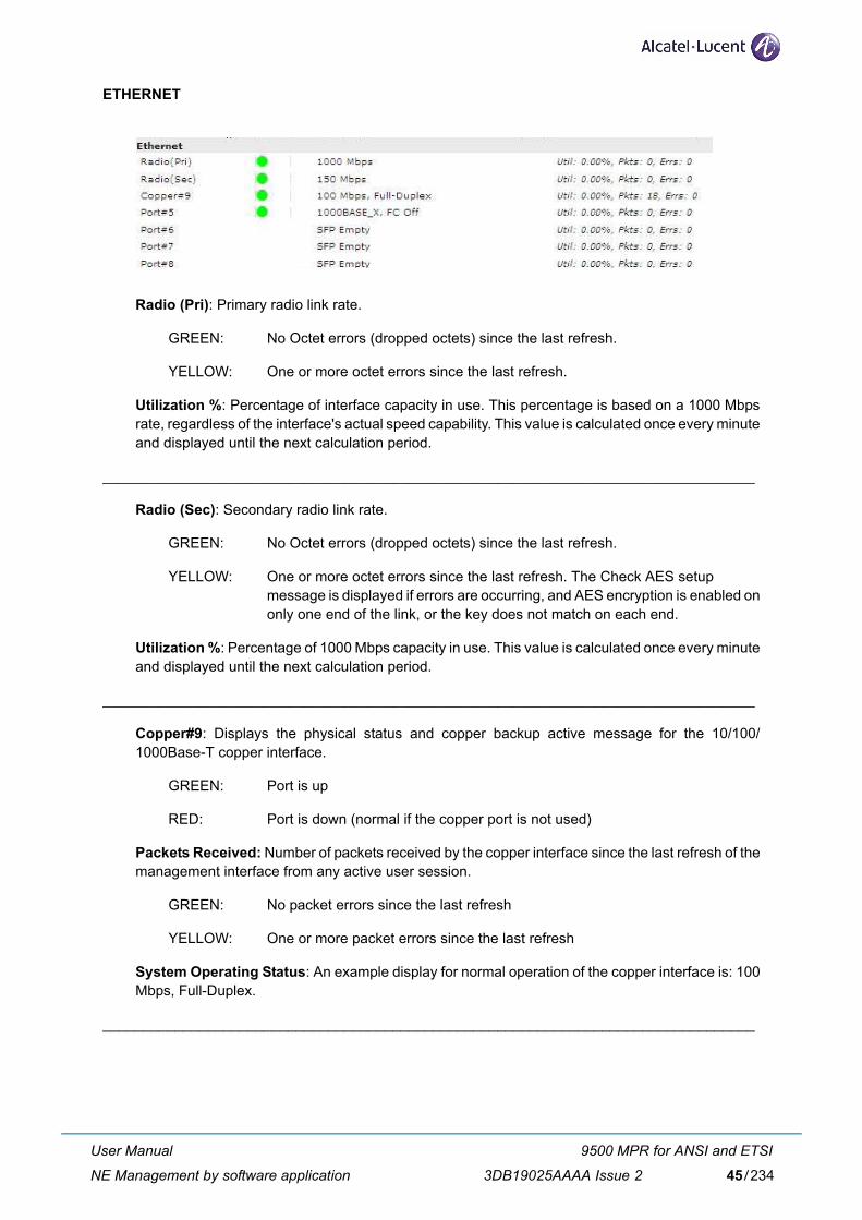
ETHERNET
Radio (Pri): Primary radio link rate.
GREEN: No Octet errors (dropped octets) since the last refresh.
YELLOW: One or more octet errors since the last refresh.
Utilization %: Percentage of interface capacity in use. This percentage is based on a 1000 Mbpsrate, regardless of the interface's actual speed capability. This value is calculated once every minuteand displayed until the next calculation period.
_________________________________________________________________________________
Radio (Sec): Secondary radio link rate.
GREEN: No Octet errors (dropped octets) since the last refresh.
YELLOW: One or more octet errors since the last refresh. The Check AES setup message is displayed if errors are occurring, and AES encryption is enabled ononly one end of the link, or the key does not match on each end.
Utilization %: Percentage of 1000 Mbps capacity in use. This value is calculated once every minuteand displayed until the next calculation period.
_________________________________________________________________________________
Copper#9: Displays the physical status and copper backup active message for the 10/100/1000Base-T copper interface.
GREEN: Port is up
RED: Port is down (normal if the copper port is not used)
Packets Received: Number of packets received by the copper interface since the last refresh of themanagement interface from any active user session.
GREEN: No packet errors since the last refresh
YELLOW: One or more packet errors since the last refresh
System Operating Status: An example display for normal operation of the copper interface is: 100Mbps, Full-Duplex.
_________________________________________________________________________________
User Manual
NE Management by software application
9500 MPR for ANSI and ETSI
3DB19025AAAA Issue 2 45/234
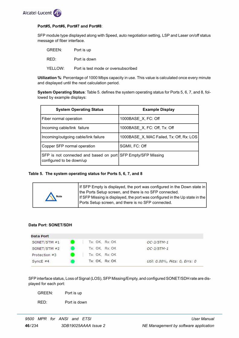
Port#5, Port#6, Port#7 and Port#8:
SFP module type displayed along with Speed, auto negotiation setting, LSP and Laser on/off statusmessage of fiber interface.
GREEN: Port is up
RED: Port is down
YELLOW: Port is test mode or oversubscribed
Utilization %: Percentage of 1000 Mbps capacity in use. This value is calculated once every minuteand displayed until the next calculation period.
System Operating Status: Table 5. defines the system operating status for Ports 5, 6, 7, and 8, fol-lowed by example displays:
Table 5. The system operating status for Ports 5, 6, 7, and 8
Data Port: SONET/SDH
SFP interface status, Loss of Signal (LOS), SFP Missing/Empty, and configured SONET/SDH rate are dis-played for each port:
GREEN: Port is up
RED: Port is down
System Operating Status Example Display
Fiber normal operation 1000BASE_X, FC: Off
Incoming cable/link failure 1000BASE_X, FC: Off, Tx: Off
Incoming/outgoing cable/link failure 1000BASE_X, MAC Failed, Tx: Off, Rx: LOS
Copper SFP normal operation SGMII, FC: Off
SFP is not connected and based on portconfigured to be down/up
SFP Empty/SFP Missing
If SFP Empty is displayed, the port was configured in the Down state inthe Ports Setup screen, and there is no SFP connected.If SFP Missing is displayed, the port was configured in the Up state in thePorts Setup screen, and there is no SFP connected.
User Manual
NE Management by software application
9500 MPR for ANSI and ETSI
3DB19025AAAA Issue 246/234
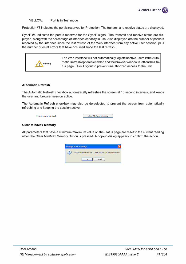
YELLOW: Port is in Test mode
Protection #3 indicates the port is reserved for Protection. The transmit and receive status are displayed.
SyncE #4 indicates the port is reserved for the SyncE signal. The transmit and receive status are dis-played, along with the percentage of interface capacity in use. Also displayed are the number of packetsreceived by the interface since the last refresh of the Web interface from any active user session, plusthe number of octet errors that have occurred since the last refresh.
Automatic Refresh
The Automatic Refresh checkbox automatically refreshes the screen at 10 second intervals, and keepsthe user and browser session active.
The Automatic Refresh checkbox may also be de-selected to prevent the screen from automaticallyrefreshing and keeping the session active.
Clear Min/Max Memory
All parameters that have a minimum/maximum value on the Status page are reset to the current readingwhen the Clear Min/Max Memory Button is pressed. A pop-up dialog appears to confirm the action.
The Web interface will not automatically log off inactive users if the Auto-matic Refresh option is enabled and the browser window is left on the Sta-tus page. Click Logout to prevent unauthorized access to the unit.
User Manual
NE Management by software application
9500 MPR for ANSI and ETSI
3DB19025AAAA Issue 2 47/234
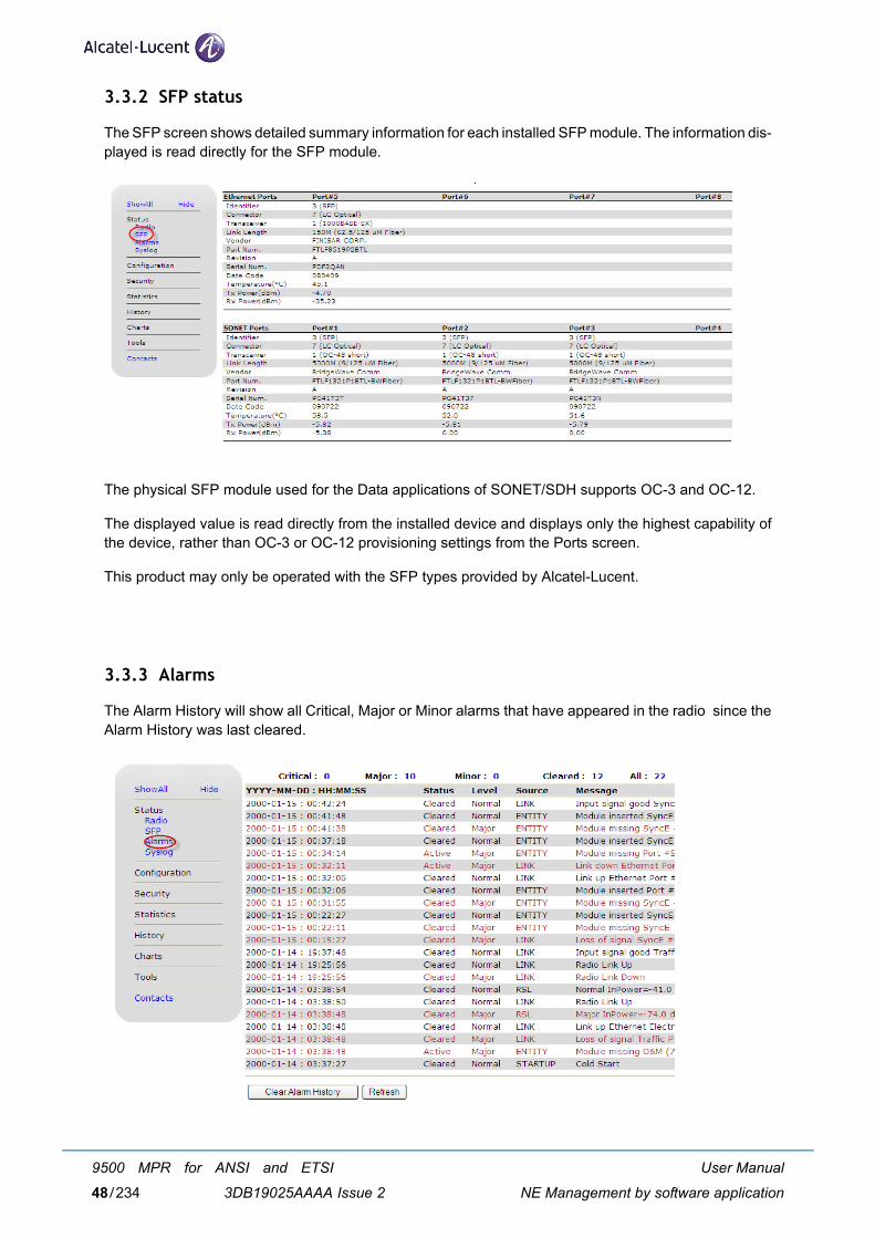
3.3.2 SFP status
The SFP screen shows detailed summary information for each installed SFP module. The information dis-played is read directly for the SFP module.
The physical SFP module used for the Data applications of SONET/SDH supports OC-3 and OC-12.
The displayed value is read directly from the installed device and displays only the highest capability ofthe device, rather than OC-3 or OC-12 provisioning settings from the Ports screen.
This product may only be operated with the SFP types provided by Alcatel-Lucent.
3.3.3 Alarms
The Alarm History will show all Critical, Major or Minor alarms that have appeared in the radio since theAlarm History was last cleared.
User Manual
NE Management by software application
9500 MPR for ANSI and ETSI
3DB19025AAAA Issue 248/234
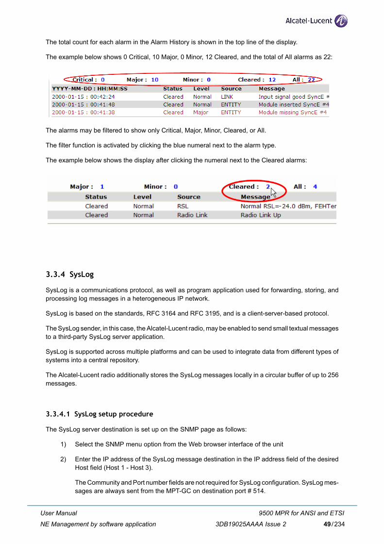
The total count for each alarm in the Alarm History is shown in the top line of the display.
The example below shows 0 Critical, 10 Major, 0 Minor, 12 Cleared, and the total of All alarms as 22:
The alarms may be filtered to show only Critical, Major, Minor, Cleared, or All.
The filter function is activated by clicking the blue numeral next to the alarm type.
The example below shows the display after clicking the numeral next to the Cleared alarms:
3.3.4 SysLog
SysLog is a communications protocol, as well as program application used for forwarding, storing, andprocessing log messages in a heterogeneous IP network.
SysLog is based on the standards, RFC 3164 and RFC 3195, and is a client-server-based protocol.
The SysLog sender, in this case, the Alcatel-Lucent radio, may be enabled to send small textual messagesto a third-party SysLog server application.
SysLog is supported across multiple platforms and can be used to integrate data from different types ofsystems into a central repository.
The Alcatel-Lucent radio additionally stores the SysLog messages locally in a circular buffer of up to 256messages.
3.3.4.1 SysLog setup procedure
The SysLog server destination is set up on the SNMP page as follows:
1) Select the SNMP menu option from the Web browser interface of the unit
2) Enter the IP address of the SysLog message destination in the IP address field of the desiredHost field (Host 1 - Host 3).
The Community and Port number fields are not required for SysLog configuration. SysLog mes-sages are always sent from the MPT-GC on destination port # 514.
User Manual
NE Management by software application
9500 MPR for ANSI and ETSI
3DB19025AAAA Issue 2 49/234
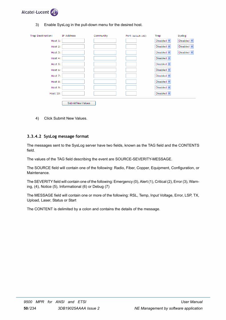
3) Enable SysLog in the pull-down menu for the desired host.
4) Click Submit New Values.
3.3.4.2 SysLog message format
The messages sent to the SysLog server have two fields, known as the TAG field and the CONTENTSfield.
The values of the TAG field describing the event are SOURCE-SEVERITY-MESSAGE.
The SOURCE field will contain one of the following: Radio, Fiber, Copper, Equipment, Configuration, orMaintenance.
The SEVERITY field will contain one of the following: Emergency (0), Alert (1), Critical (2), Error (3), Warn-ing, (4), Notice (5), Informational (6) or Debug (7)
The MESSAGE field will contain one or more of the following: RSL, Temp, Input Voltage, Error, LSP, TX,Upload, Laser, Status or Start
The CONTENT is delimited by a colon and contains the details of the message.
User Manual
NE Management by software application
9500 MPR for ANSI and ETSI
3DB19025AAAA Issue 250/234
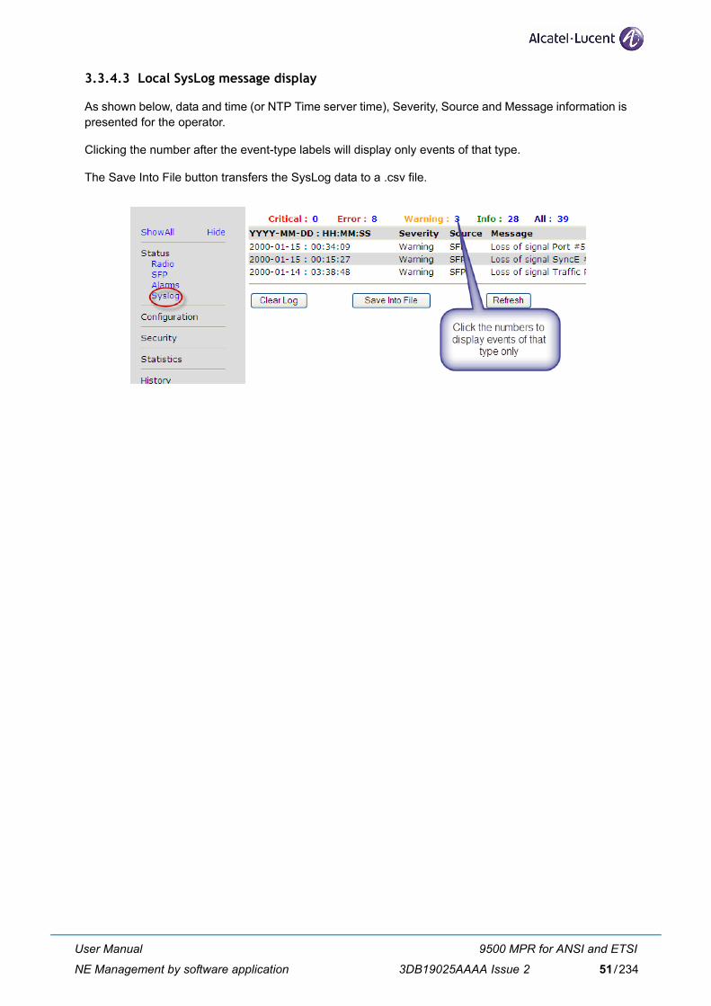
3.3.4.3 Local SysLog message display
As shown below, data and time (or NTP Time server time), Severity, Source and Message information ispresented for the operator.
Clicking the number after the event-type labels will display only events of that type.
The Save Into File button transfers the SysLog data to a .csv file.
User Manual
NE Management by software application
9500 MPR for ANSI and ETSI
3DB19025AAAA Issue 2 51/234
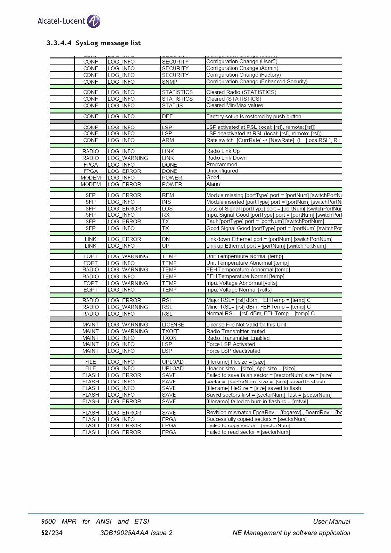
3.3.4.4 SysLog message list
User Manual
NE Management by software application
9500 MPR for ANSI and ETSI
3DB19025AAAA Issue 252/234
3.4 Configuration menu
The initial installation of the units involves configuring the following:
– IP addresses
– Radio link
– ARM
– VLAN and management access
– Ports
– Time service (STNP or RTC)
– SNMP
– LSP (synchronous or AdaptPath)
– ECFM and EOAM
– QoS
– SyncE
– 1+1 Hot Standby Protection
The wireless link should be physically installed following the instructions found in the corresponding instal-lation manual provided with the link.
Alcatel-Lucent verified Web interface operation with versions IE7 and IE8 of Microsoft Internet Explorer.
Configuration changes are saved to flash for recall upon system hard restart or power-cycle.
The following features will only be visible in the Web interface if licensed:ECFM, EOAM, QoS, SyncE, and 1+1 Hot Standby Protection.
Traffic is momentarily disrupted when port, VLAN, radio link, or ARM con-figuration changes are saved.
User Manual
NE Management by software application
9500 MPR for ANSI and ETSI
3DB19025AAAA Issue 2 53/234
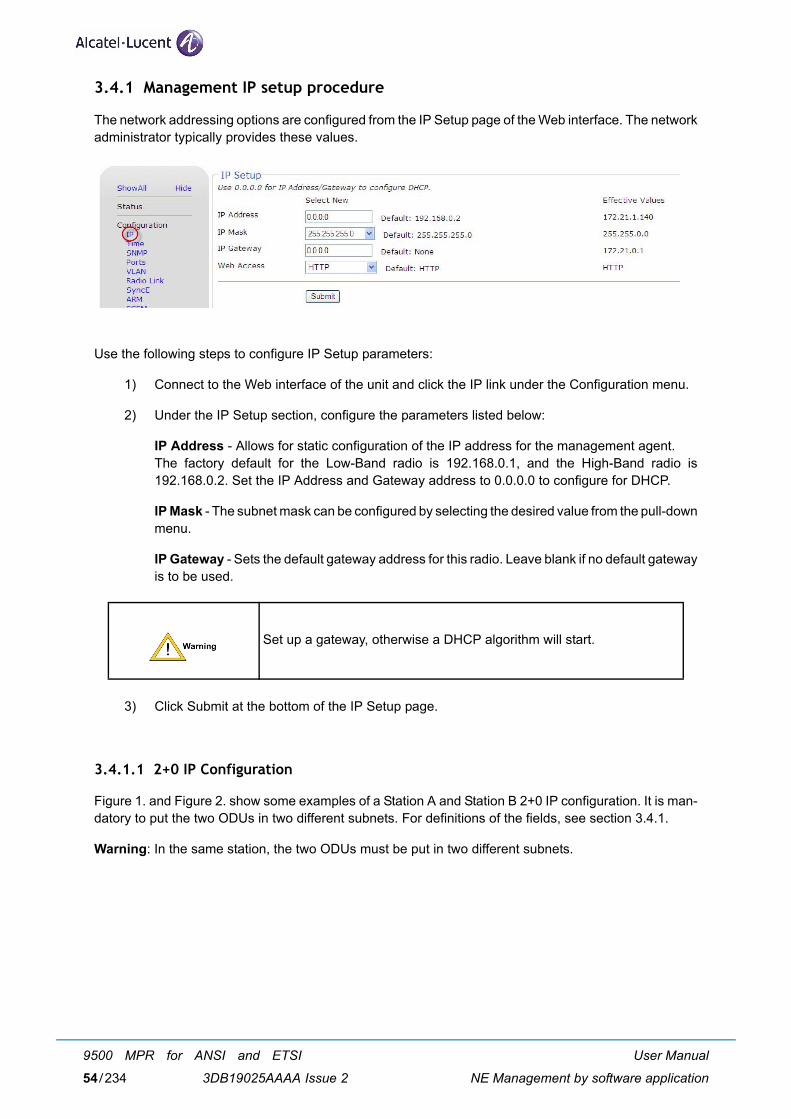
3.4.1 Management IP setup procedure
The network addressing options are configured from the IP Setup page of the Web interface. The networkadministrator typically provides these values.
Use the following steps to configure IP Setup parameters:
1) Connect to the Web interface of the unit and click the IP link under the Configuration menu.
2) Under the IP Setup section, configure the parameters listed below:
IP Address - Allows for static configuration of the IP address for the management agent. The factory default for the Low-Band radio is 192.168.0.1, and the High-Band radio is192.168.0.2. Set the IP Address and Gateway address to 0.0.0.0 to configure for DHCP.
IP Mask - The subnet mask can be configured by selecting the desired value from the pull-downmenu.
IP Gateway - Sets the default gateway address for this radio. Leave blank if no default gatewayis to be used.
3) Click Submit at the bottom of the IP Setup page.
3.4.1.1 2+0 IP Configuration
Figure 1. and Figure 2. show some examples of a Station A and Station B 2+0 IP configuration. It is man-datory to put the two ODUs in two different subnets. For definitions of the fields, see section 3.4.1.
Warning: In the same station, the two ODUs must be put in two different subnets.
Set up a gateway, otherwise a DHCP algorithm will start.
User Manual
NE Management by software application
9500 MPR for ANSI and ETSI
3DB19025AAAA Issue 254/234
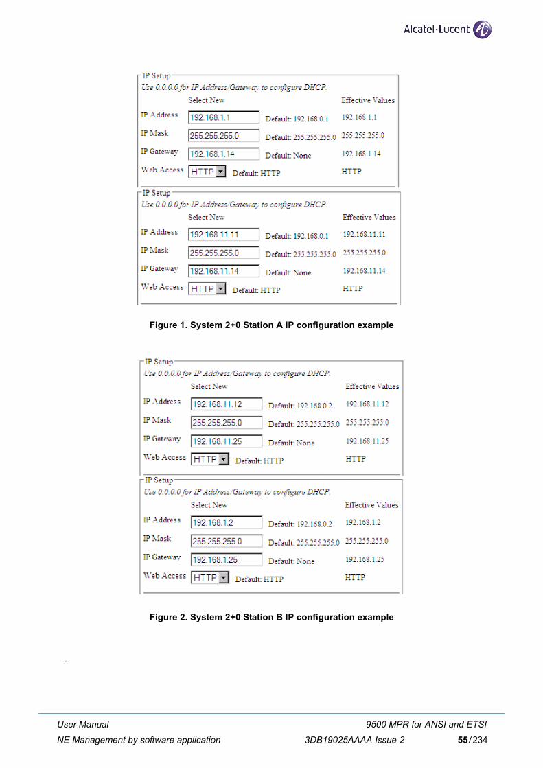
Figure 1. System 2+0 Station A IP configuration example
Figure 2. System 2+0 Station B IP configuration example
.
User Manual
NE Management by software application
9500 MPR for ANSI and ETSI
3DB19025AAAA Issue 2 55/234
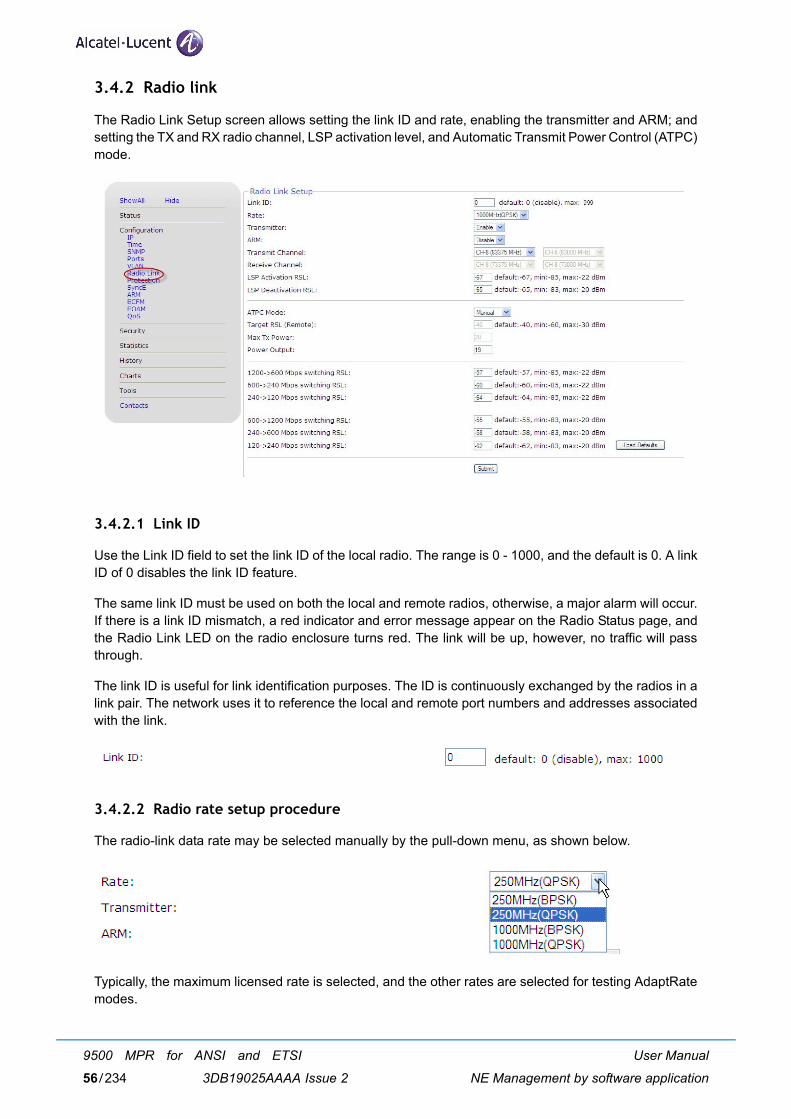
3.4.2 Radio link
The Radio Link Setup screen allows setting the link ID and rate, enabling the transmitter and ARM; andsetting the TX and RX radio channel, LSP activation level, and Automatic Transmit Power Control (ATPC)mode.
3.4.2.1 Link ID
Use the Link ID field to set the link ID of the local radio. The range is 0 - 1000, and the default is 0. A linkID of 0 disables the link ID feature.
The same link ID must be used on both the local and remote radios, otherwise, a major alarm will occur.If there is a link ID mismatch, a red indicator and error message appear on the Radio Status page, andthe Radio Link LED on the radio enclosure turns red. The link will be up, however, no traffic will passthrough.
The link ID is useful for link identification purposes. The ID is continuously exchanged by the radios in alink pair. The network uses it to reference the local and remote port numbers and addresses associatedwith the link.
3.4.2.2 Radio rate setup procedure
The radio-link data rate may be selected manually by the pull-down menu, as shown below.
Typically, the maximum licensed rate is selected, and the other rates are selected for testing AdaptRatemodes.
User Manual
NE Management by software application
9500 MPR for ANSI and ETSI
3DB19025AAAA Issue 256/234
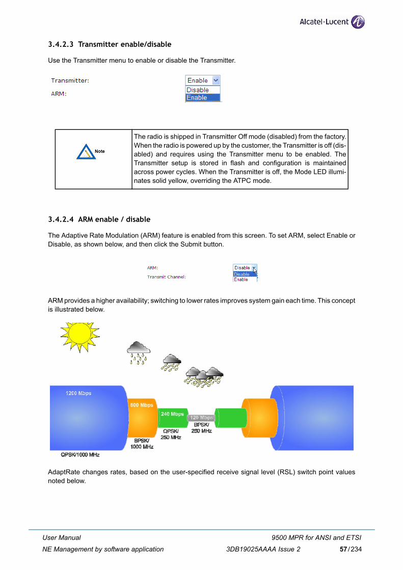
3.4.2.3 Transmitter enable/disable
Use the Transmitter menu to enable or disable the Transmitter.
3.4.2.4 ARM enable / disable
The Adaptive Rate Modulation (ARM) feature is enabled from this screen. To set ARM, select Enable orDisable, as shown below, and then click the Submit button.
ARM provides a higher availability; switching to lower rates improves system gain each time. This conceptis illustrated below.
AdaptRate changes rates, based on the user-specified receive signal level (RSL) switch point valuesnoted below.
The radio is shipped in Transmitter Off mode (disabled) from the factory.When the radio is powered up by the customer, the Transmitter is off (dis-abled) and requires using the Transmitter menu to be enabled. TheTransmitter setup is stored in flash and configuration is maintainedacross power cycles. When the Transmitter is off, the Mode LED illumi-nates solid yellow, overriding the ATPC mode.
User Manual
NE Management by software application
9500 MPR for ANSI and ETSI
3DB19025AAAA Issue 2 57/234
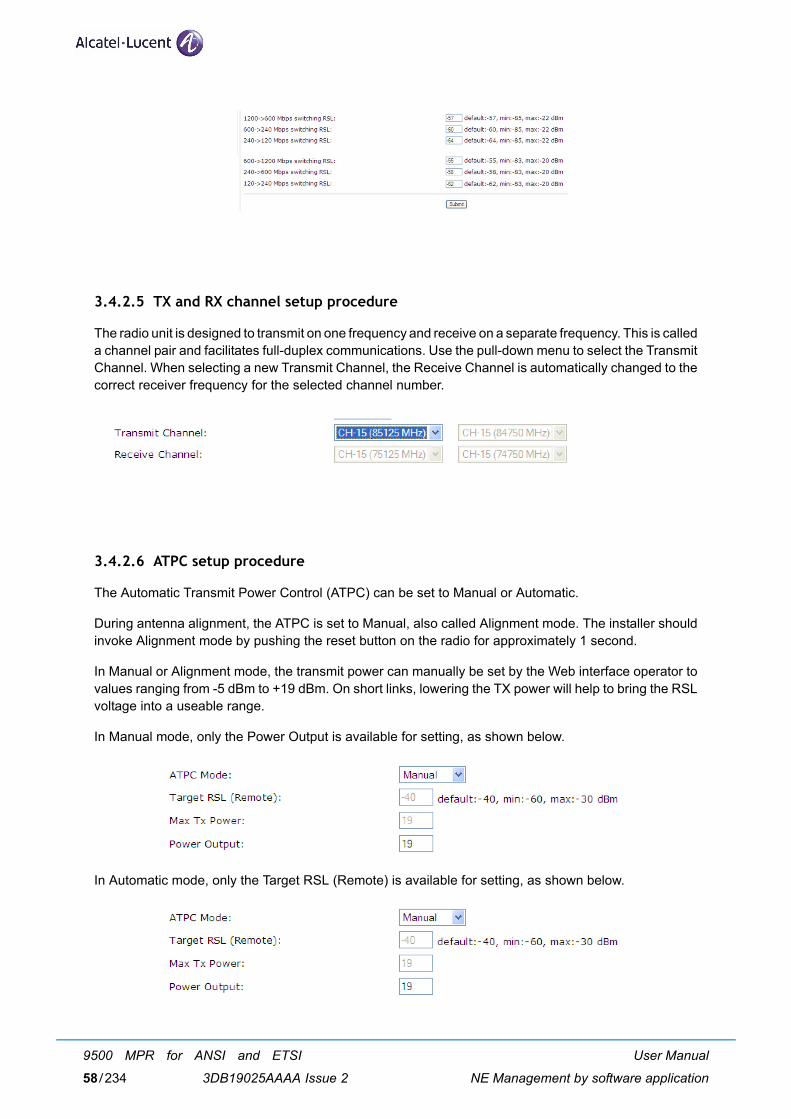
3.4.2.5 TX and RX channel setup procedure
The radio unit is designed to transmit on one frequency and receive on a separate frequency. This is calleda channel pair and facilitates full-duplex communications. Use the pull-down menu to select the TransmitChannel. When selecting a new Transmit Channel, the Receive Channel is automatically changed to thecorrect receiver frequency for the selected channel number.
3.4.2.6 ATPC setup procedure
The Automatic Transmit Power Control (ATPC) can be set to Manual or Automatic.
During antenna alignment, the ATPC is set to Manual, also called Alignment mode. The installer shouldinvoke Alignment mode by pushing the reset button on the radio for approximately 1 second.
In Manual or Alignment mode, the transmit power can manually be set by the Web interface operator tovalues ranging from -5 dBm to +19 dBm. On short links, lowering the TX power will help to bring the RSLvoltage into a useable range.
In Manual mode, only the Power Output is available for setting, as shown below.
In Automatic mode, only the Target RSL (Remote) is available for setting, as shown below.
User Manual
NE Management by software application
9500 MPR for ANSI and ETSI
3DB19025AAAA Issue 258/234
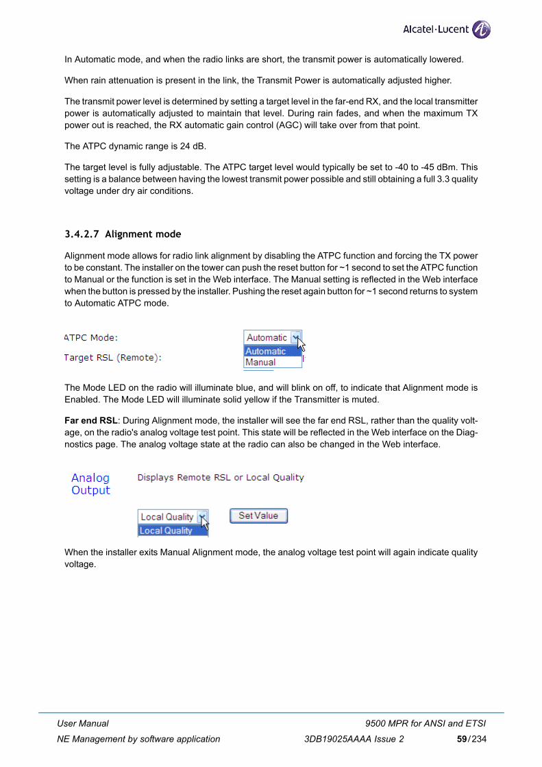
In Automatic mode, and when the radio links are short, the transmit power is automatically lowered.
When rain attenuation is present in the link, the Transmit Power is automatically adjusted higher.
The transmit power level is determined by setting a target level in the far-end RX, and the local transmitterpower is automatically adjusted to maintain that level. During rain fades, and when the maximum TXpower out is reached, the RX automatic gain control (AGC) will take over from that point.
The ATPC dynamic range is 24 dB.
The target level is fully adjustable. The ATPC target level would typically be set to -40 to -45 dBm. Thissetting is a balance between having the lowest transmit power possible and still obtaining a full 3.3 qualityvoltage under dry air conditions.
3.4.2.7 Alignment mode
Alignment mode allows for radio link alignment by disabling the ATPC function and forcing the TX powerto be constant. The installer on the tower can push the reset button for ~1 second to set the ATPC functionto Manual or the function is set in the Web interface. The Manual setting is reflected in the Web interfacewhen the button is pressed by the installer. Pushing the reset again button for ~1 second returns to systemto Automatic ATPC mode.
The Mode LED on the radio will illuminate blue, and will blink on off, to indicate that Alignment mode isEnabled. The Mode LED will illuminate solid yellow if the Transmitter is muted.
Far end RSL: During Alignment mode, the installer will see the far end RSL, rather than the quality volt-age, on the radio's analog voltage test point. This state will be reflected in the Web interface on the Diag-nostics page. The analog voltage state at the radio can also be changed in the Web interface.
When the installer exits Manual Alignment mode, the analog voltage test point will again indicate qualityvoltage.
User Manual
NE Management by software application
9500 MPR for ANSI and ETSI
3DB19025AAAA Issue 2 59/234
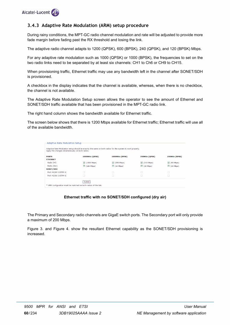
3.4.3 Adaptive Rate Modulation (ARM) setup procedure
During rainy conditions, the MPT-GC radio channel modulation and rate will be adjusted to provide morefade margin before fading past the RX threshold and losing the link.
The adaptive radio channel adapts to 1200 (QPSK), 600 (BPSK), 240 (QPSK), and 120 (BPSK) Mbps.
For any adaptive rate modulation such as 1000 (QPSK) or 1000 (BPSK), the frequencies to set on thetwo radio links need to be separated by at least six channels: CH1 to Ch6 or CH9 to CH15.
When provisioning traffic, Ethernet traffic may use any bandwidth left in the channel after SONET/SDHis provisioned.
A checkbox in the display indicates that the channel is available, whereas, when there is no checkbox,the channel is not available.
The Adaptive Rate Modulation Setup screen allows the operator to see the amount of Ethernet andSONET/SDH traffic available that has been provisioned in the MPT-GC radio link.
The right hand column shows the bandwidth available for Ethernet traffic.
The screen below shows that there is 1200 Mbps available for Ethernet traffic; Ethernet traffic will use allof the available bandwidth.
Ethernet traffic with no SONET/SDH configured (dry air)
The Primary and Secondary radio channels are GigaE switch ports. The Secondary port will only providea maximum of 200 Mbps.
Figure 3. and Figure 4. show the resultant Ethernet capability as the SONET/SDH provisioning isincreased.
User Manual
NE Management by software application
9500 MPR for ANSI and ETSI
3DB19025AAAA Issue 260/234
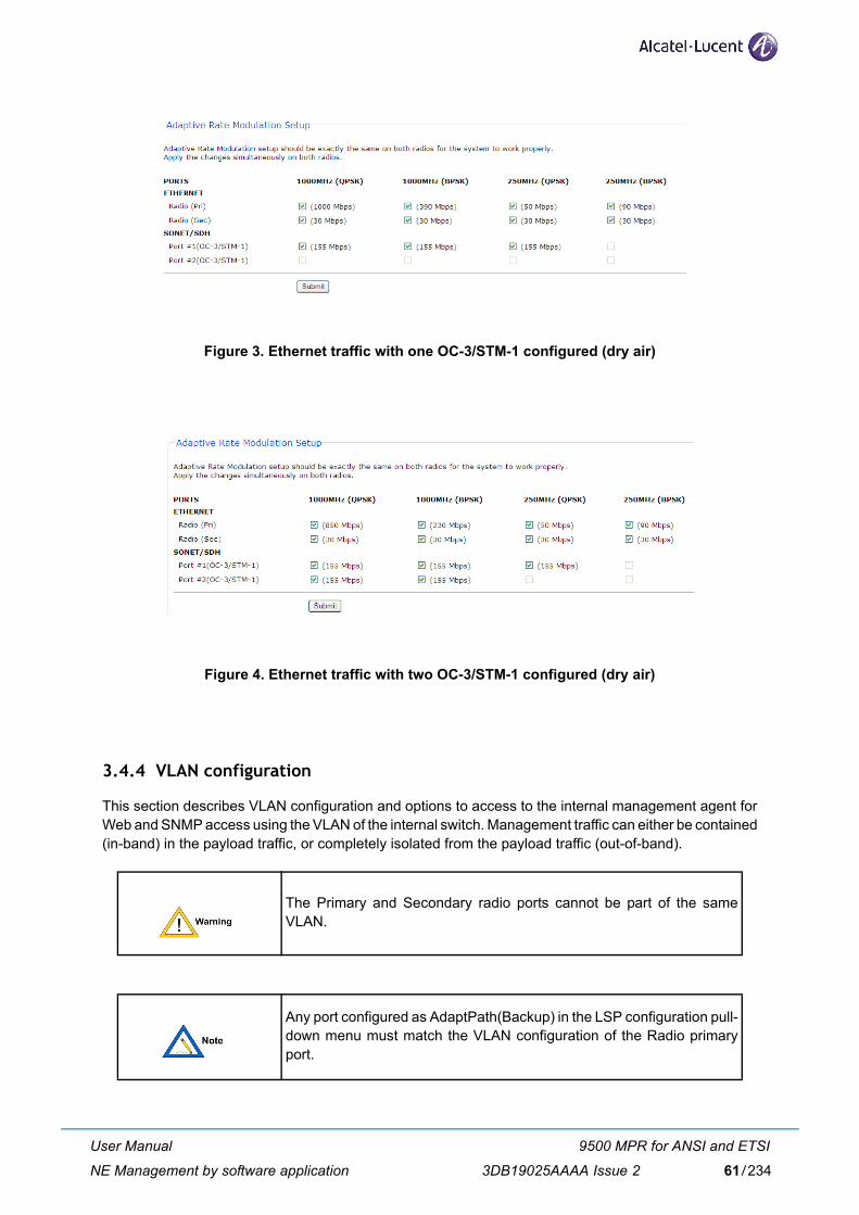
Figure 3. Ethernet traffic with one OC-3/STM-1 configured (dry air)
Figure 4. Ethernet traffic with two OC-3/STM-1 configured (dry air)
3.4.4 VLAN configuration
This section describes VLAN configuration and options to access to the internal management agent forWeb and SNMP access using the VLAN of the internal switch. Management traffic can either be contained(in-band) in the payload traffic, or completely isolated from the payload traffic (out-of-band).
The Primary and Secondary radio ports cannot be part of the sameVLAN.
Any port configured as AdaptPath(Backup) in the LSP configuration pull-down menu must match the VLAN configuration of the Radio primaryport.
User Manual
NE Management by software application
9500 MPR for ANSI and ETSI
3DB19025AAAA Issue 2 61/234
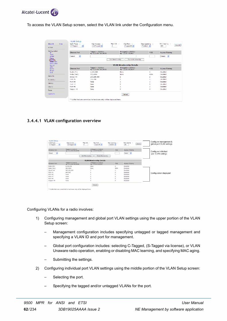
To access the VLAN Setup screen, select the VLAN link under the Configuration menu.
3.4.4.1 VLAN configuration overview
Configuring VLANs for a radio involves:
1) Configuring management and global port VLAN settings using the upper portion of the VLANSetup screen:
– Management configuration includes specifying untagged or tagged management andspecifying a VLAN ID and port for management.
– Global port configuration includes: selecting C-Tagged, (S-Tagged via license), or VLANUnaware radio operation, enabling or disabling MAC learning, and specifying MAC aging.
– Submitting the settings.
2) Configuring individual port VLAN settings using the middle portion of the VLAN Setup screen:
– Selecting the port.
– Specifying the tagged and/or untagged VLANs for the port.
User Manual
NE Management by software application
9500 MPR for ANSI and ETSI
3DB19025AAAA Issue 262/234
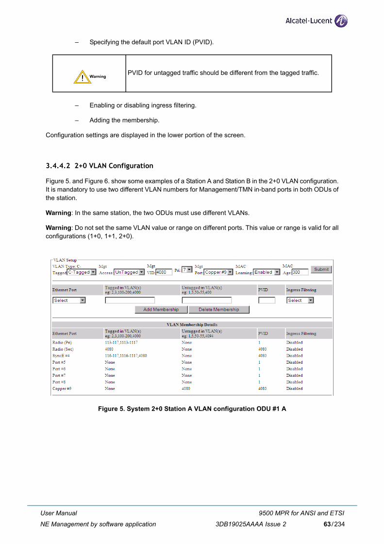
– Specifying the default port VLAN ID (PVID).
– Enabling or disabling ingress filtering.
– Adding the membership.
Configuration settings are displayed in the lower portion of the screen.
3.4.4.2 2+0 VLAN Configuration
Figure 5. and Figure 6. show some examples of a Station A and Station B in the 2+0 VLAN configuration.It is mandatory to use two different VLAN numbers for Management/TMN in-band ports in both ODUs ofthe station.
Warning: In the same station, the two ODUs must use different VLANs.
Warning: Do not set the same VLAN value or range on different ports. This value or range is valid for allconfigurations (1+0, 1+1, 2+0).
Figure 5. System 2+0 Station A VLAN configuration ODU #1 A
PVID for untagged traffic should be different from the tagged traffic.
User Manual
NE Management by software application
9500 MPR for ANSI and ETSI
3DB19025AAAA Issue 2 63/234
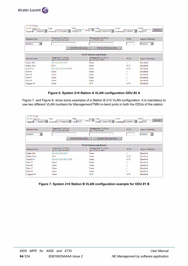
Figure 6. System 2+0 Station A VLAN configuration ODU #2 A
Figure 7. and Figure 8. show some examples of a Station B 2+0 VLAN configuration. It is mandatory touse two different VLAN numbers for Management/TMN in-band ports in both the ODUs of the station.
Figure 7. System 2+0 Station B VLAN configuration example for ODU #1 B
User Manual
NE Management by software application
9500 MPR for ANSI and ETSI
3DB19025AAAA Issue 264/234
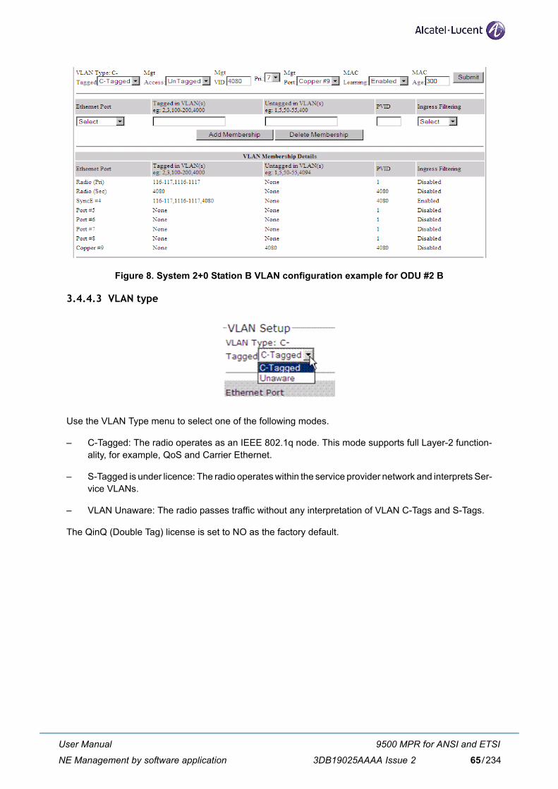
Figure 8. System 2+0 Station B VLAN configuration example for ODU #2 B
3.4.4.3 VLAN type
Use the VLAN Type menu to select one of the following modes.
– C-Tagged: The radio operates as an IEEE 802.1q node. This mode supports full Layer-2 function-ality, for example, QoS and Carrier Ethernet.
– S-Tagged is under licence: The radio operates within the service provider network and interprets Ser-vice VLANs.
– VLAN Unaware: The radio passes traffic without any interpretation of VLAN C-Tags and S-Tags.
The QinQ (Double Tag) license is set to NO as the factory default.
User Manual
NE Management by software application
9500 MPR for ANSI and ETSI
3DB19025AAAA Issue 2 65/234
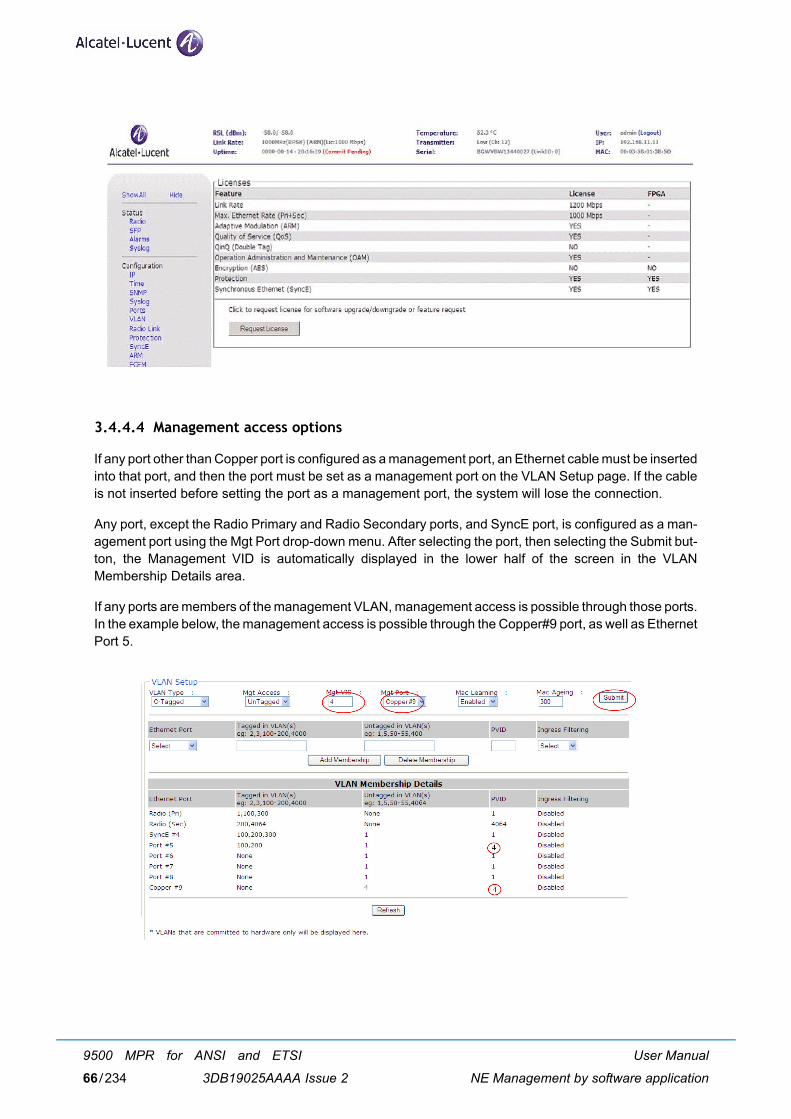
3.4.4.4 Management access options
If any port other than Copper port is configured as a management port, an Ethernet cable must be insertedinto that port, and then the port must be set as a management port on the VLAN Setup page. If the cableis not inserted before setting the port as a management port, the system will lose the connection.
Any port, except the Radio Primary and Radio Secondary ports, and SyncE port, is configured as a man-agement port using the Mgt Port drop-down menu. After selecting the port, then selecting the Submit but-ton, the Management VID is automatically displayed in the lower half of the screen in the VLANMembership Details area.
If any ports are members of the management VLAN, management access is possible through those ports.In the example below, the management access is possible through the Copper#9 port, as well as EthernetPort 5.
User Manual
NE Management by software application
9500 MPR for ANSI and ETSI
3DB19025AAAA Issue 266/234
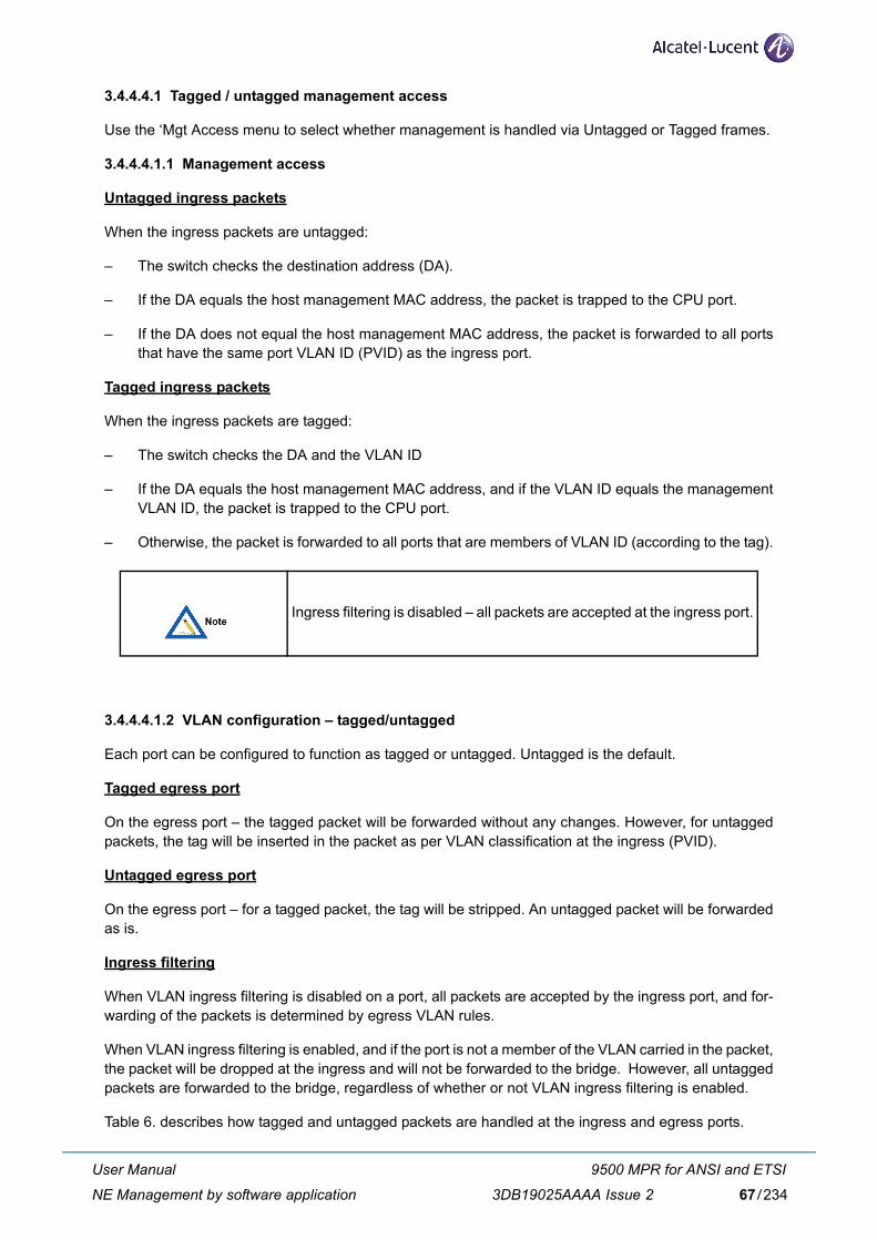
3.4.4.4.1 Tagged / untagged management access
Use the ‘Mgt Access menu to select whether management is handled via Untagged or Tagged frames.
3.4.4.4.1.1 Management access
Untagged ingress packets
When the ingress packets are untagged:
– The switch checks the destination address (DA).
– If the DA equals the host management MAC address, the packet is trapped to the CPU port.
– If the DA does not equal the host management MAC address, the packet is forwarded to all portsthat have the same port VLAN ID (PVID) as the ingress port.
Tagged ingress packets
When the ingress packets are tagged:
– The switch checks the DA and the VLAN ID
– If the DA equals the host management MAC address, and if the VLAN ID equals the managementVLAN ID, the packet is trapped to the CPU port.
– Otherwise, the packet is forwarded to all ports that are members of VLAN ID (according to the tag).
3.4.4.4.1.2 VLAN configuration – tagged/untagged
Each port can be configured to function as tagged or untagged. Untagged is the default.
Tagged egress port
On the egress port – the tagged packet will be forwarded without any changes. However, for untaggedpackets, the tag will be inserted in the packet as per VLAN classification at the ingress (PVID).
Untagged egress port
On the egress port – for a tagged packet, the tag will be stripped. An untagged packet will be forwardedas is.
Ingress filtering
When VLAN ingress filtering is disabled on a port, all packets are accepted by the ingress port, and for-warding of the packets is determined by egress VLAN rules.
When VLAN ingress filtering is enabled, and if the port is not a member of the VLAN carried in the packet,the packet will be dropped at the ingress and will not be forwarded to the bridge. However, all untaggedpackets are forwarded to the bridge, regardless of whether or not VLAN ingress filtering is enabled.
Table 6. describes how tagged and untagged packets are handled at the ingress and egress ports.
Ingress filtering is disabled – all packets are accepted at the ingress port.
User Manual
NE Management by software application
9500 MPR for ANSI and ETSI
3DB19025AAAA Issue 2 67/234
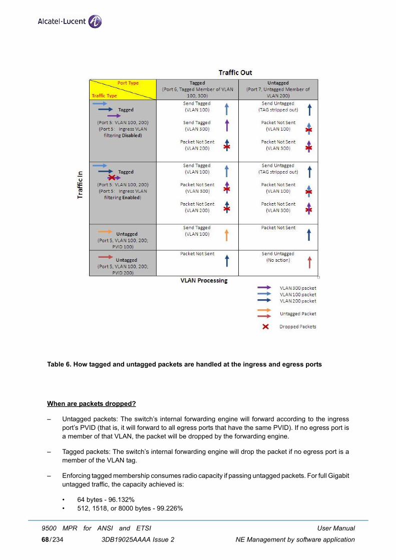
Table 6. How tagged and untagged packets are handled at the ingress and egress ports
When are packets dropped?
– Untagged packets: The switch’s internal forwarding engine will forward according to the ingressport’s PVID (that is, it will forward to all egress ports that have the same PVID). If no egress port isa member of that VLAN, the packet will be dropped by the forwarding engine.
– Tagged packets: The switch’s internal forwarding engine will drop the packet if no egress port is amember of the VLAN tag.
– Enforcing tagged membership consumes radio capacity if passing untagged packets. For full Gigabituntagged traffic, the capacity achieved is:
• 64 bytes - 96.132%• 512, 1518, or 8000 bytes - 99.226%
User Manual
NE Management by software application
9500 MPR for ANSI and ETSI
3DB19025AAAA Issue 268/234
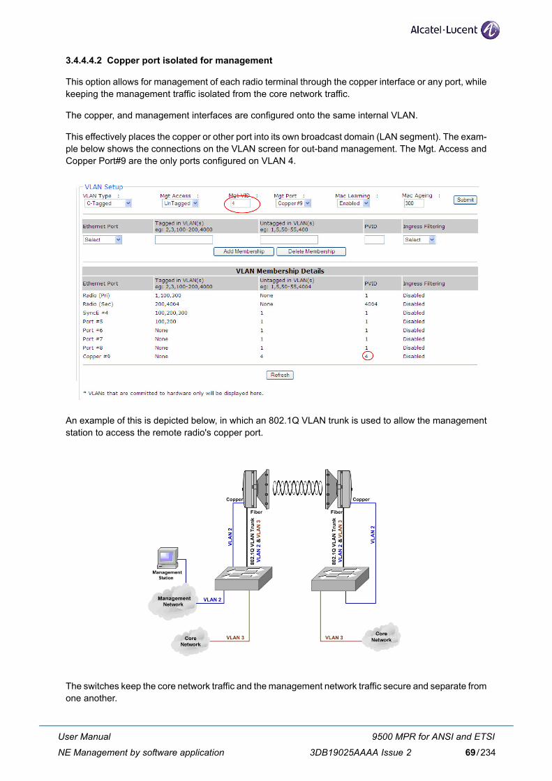
3.4.4.4.2 Copper port isolated for management
This option allows for management of each radio terminal through the copper interface or any port, whilekeeping the management traffic isolated from the core network traffic.
The copper, and management interfaces are configured onto the same internal VLAN.
This effectively places the copper or other port into its own broadcast domain (LAN segment). The exam-ple below shows the connections on the VLAN screen for out-band management. The Mgt. Access andCopper Port#9 are the only ports configured on VLAN 4.
An example of this is depicted below, in which an 802.1Q VLAN trunk is used to allow the managementstation to access the remote radio's copper port.
The switches keep the core network traffic and the management network traffic secure and separate fromone another.
User Manual
NE Management by software application
9500 MPR for ANSI and ETSI
3DB19025AAAA Issue 2 69/234
3.4.4.4.3 Management access setup procedure
Use the following steps to configure the management access:
1) Connect to the Web interface of the unit and select the VLAN Setup page.
2) Specify whether management is handled via untagged or tagged frames using the Mgt Accessmenu.
3) Type in the VLAN ID to be used for management in the Mgt VID field.
4) Select the port to be used for management from the Mgt Port drop-down menu.
5) Click Submit.
6) To provide management access to additional ports, select the port from the Ethernet Port drop-down menu, and type in the VLAN ID used for management in the PVID field (same VLAN IDas entered in the Mgt VID field). Then click Add Membership.
3.4.4.5 MAC learning enable / disable
The MPT-GC radio link acts as a network bridge. The MPT-GC contains a bridging or forwarding table.The MPT-GC examines the source addresses in received packet headers to locate unknown devices. Adevice will either be local, or local to the far end of the link. Use the Mac Learning menu to enable or disableMAC Learning.
When MAC learning is enabled, the switch dynamically learns the MAC addresses and directs the trafficto a target port, provided the destination MAC address is already learned. If the MAC address is notlearned (that is, no entry in the forwarding database) the packet will be forwarded to all egress ports withinthe VLAN.
When MAC learning is disabled, all packets will be forwarded to all ports within the VLAN.
3.4.4.6 MAC ageing
Use the MAC Ageing field to set the maximum age of a dynamically learned entry in the MAC addresstable. The range is 10 - 630 seconds. When the maximum age is reached, the MAC address entries areremoved, given that the packet with the learned MAC entry as source does not enter the switch in thisperiod.
User Manual
NE Management by software application
9500 MPR for ANSI and ETSI
3DB19025AAAA Issue 270/234
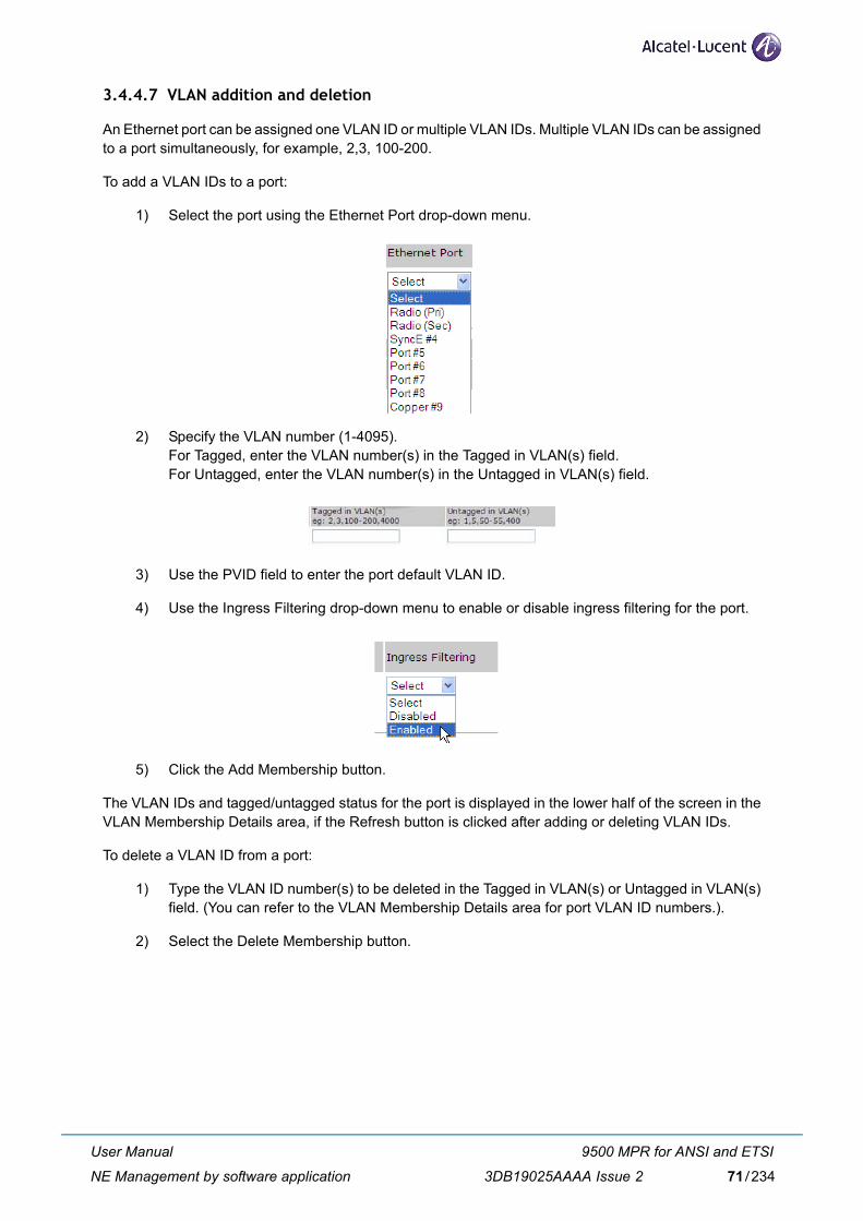
3.4.4.7 VLAN addition and deletion
An Ethernet port can be assigned one VLAN ID or multiple VLAN IDs. Multiple VLAN IDs can be assignedto a port simultaneously, for example, 2,3, 100-200.
To add a VLAN IDs to a port:
1) Select the port using the Ethernet Port drop-down menu.
2) Specify the VLAN number (1-4095).For Tagged, enter the VLAN number(s) in the Tagged in VLAN(s) field.For Untagged, enter the VLAN number(s) in the Untagged in VLAN(s) field.
3) Use the PVID field to enter the port default VLAN ID.
4) Use the Ingress Filtering drop-down menu to enable or disable ingress filtering for the port.
5) Click the Add Membership button.
The VLAN IDs and tagged/untagged status for the port is displayed in the lower half of the screen in theVLAN Membership Details area, if the Refresh button is clicked after adding or deleting VLAN IDs.
To delete a VLAN ID from a port:
1) Type the VLAN ID number(s) to be deleted in the Tagged in VLAN(s) or Untagged in VLAN(s)field. (You can refer to the VLAN Membership Details area for port VLAN ID numbers.).
2) Select the Delete Membership button.
User Manual
NE Management by software application
9500 MPR for ANSI and ETSI
3DB19025AAAA Issue 2 71/234
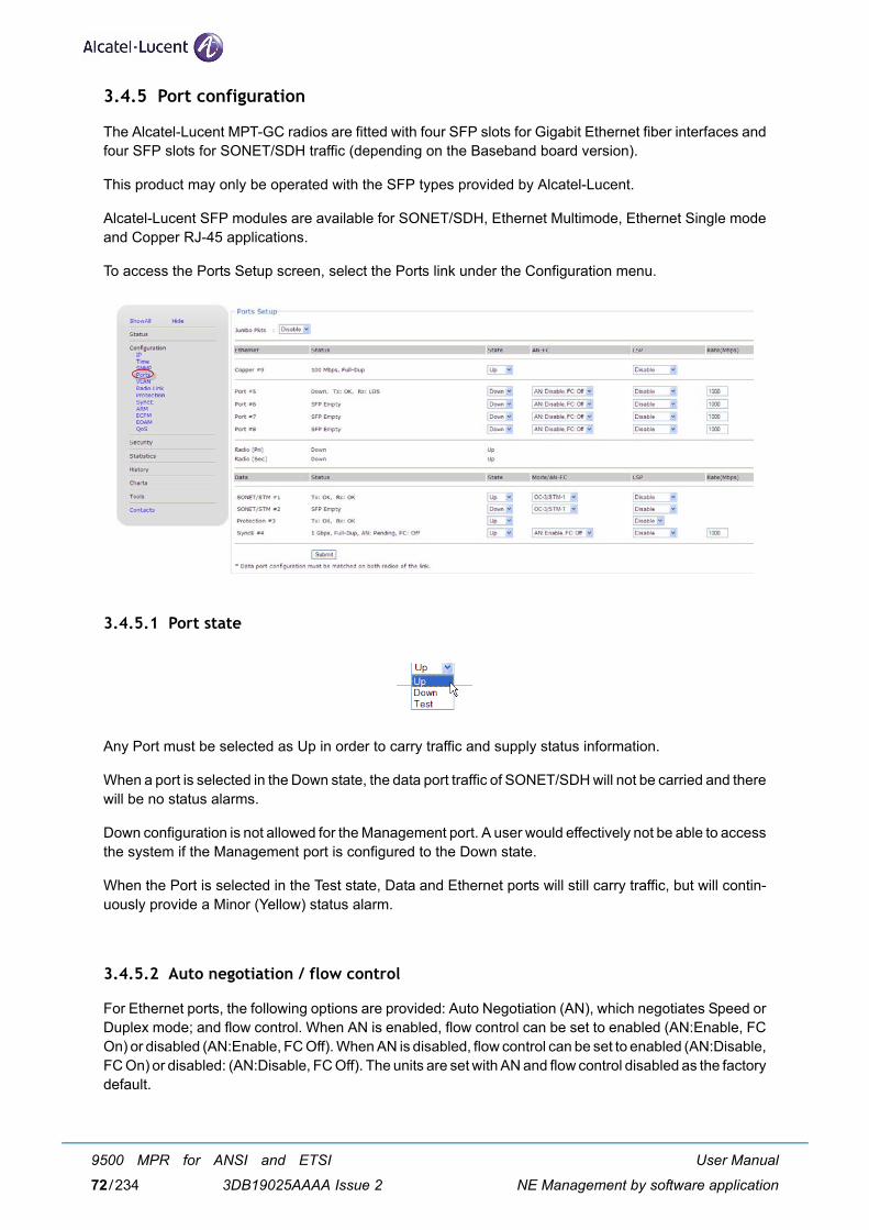
3.4.5 Port configuration
The Alcatel-Lucent MPT-GC radios are fitted with four SFP slots for Gigabit Ethernet fiber interfaces andfour SFP slots for SONET/SDH traffic (depending on the Baseband board version).
This product may only be operated with the SFP types provided by Alcatel-Lucent.
Alcatel-Lucent SFP modules are available for SONET/SDH, Ethernet Multimode, Ethernet Single modeand Copper RJ-45 applications.
To access the Ports Setup screen, select the Ports link under the Configuration menu.
3.4.5.1 Port state
Any Port must be selected as Up in order to carry traffic and supply status information.
When a port is selected in the Down state, the data port traffic of SONET/SDH will not be carried and therewill be no status alarms.
Down configuration is not allowed for the Management port. A user would effectively not be able to accessthe system if the Management port is configured to the Down state.
When the Port is selected in the Test state, Data and Ethernet ports will still carry traffic, but will contin-uously provide a Minor (Yellow) status alarm.
3.4.5.2 Auto negotiation / flow control
For Ethernet ports, the following options are provided: Auto Negotiation (AN), which negotiates Speed orDuplex mode; and flow control. When AN is enabled, flow control can be set to enabled (AN:Enable, FCOn) or disabled (AN:Enable, FC Off). When AN is disabled, flow control can be set to enabled (AN:Disable,FC On) or disabled: (AN:Disable, FC Off). The units are set with AN and flow control disabled as the factorydefault.
User Manual
NE Management by software application
9500 MPR for ANSI and ETSI
3DB19025AAAA Issue 272/234
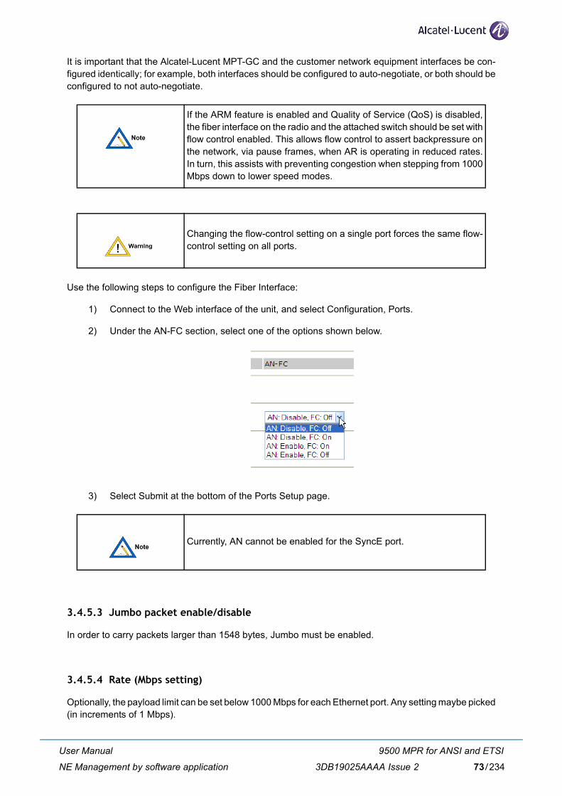
It is important that the Alcatel-Lucent MPT-GC and the customer network equipment interfaces be con-figured identically; for example, both interfaces should be configured to auto-negotiate, or both should beconfigured to not auto-negotiate.
Use the following steps to configure the Fiber Interface:
1) Connect to the Web interface of the unit, and select Configuration, Ports.
2) Under the AN-FC section, select one of the options shown below.
3) Select Submit at the bottom of the Ports Setup page.
3.4.5.3 Jumbo packet enable/disable
In order to carry packets larger than 1548 bytes, Jumbo must be enabled.
3.4.5.4 Rate (Mbps setting)
Optionally, the payload limit can be set below 1000 Mbps for each Ethernet port. Any setting maybe picked(in increments of 1 Mbps).
If the ARM feature is enabled and Quality of Service (QoS) is disabled,the fiber interface on the radio and the attached switch should be set withflow control enabled. This allows flow control to assert backpressure onthe network, via pause frames, when AR is operating in reduced rates.In turn, this assists with preventing congestion when stepping from 1000Mbps down to lower speed modes.
Changing the flow-control setting on a single port forces the same flow-control setting on all ports.
Currently, AN cannot be enabled for the SyncE port.
User Manual
NE Management by software application
9500 MPR for ANSI and ETSI
3DB19025AAAA Issue 2 73/234
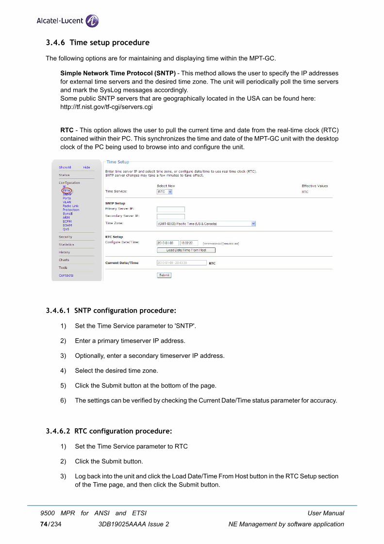
3.4.6 Time setup procedure
The following options are for maintaining and displaying time within the MPT-GC.
Simple Network Time Protocol (SNTP) - This method allows the user to specify the IP addressesfor external time servers and the desired time zone. The unit will periodically poll the time serversand mark the SysLog messages accordingly.Some public SNTP servers that are geographically located in the USA can be found here:http://tf.nist.gov/tf-cgi/servers.cgi
RTC - This option allows the user to pull the current time and date from the real-time clock (RTC)contained within their PC. This synchronizes the time and date of the MPT-GC unit with the desktopclock of the PC being used to browse into and configure the unit.
3.4.6.1 SNTP configuration procedure:
1) Set the Time Service parameter to 'SNTP'.
2) Enter a primary timeserver IP address.
3) Optionally, enter a secondary timeserver IP address.
4) Select the desired time zone.
5) Click the Submit button at the bottom of the page.
6) The settings can be verified by checking the Current Date/Time status parameter for accuracy.
3.4.6.2 RTC configuration procedure:
1) Set the Time Service parameter to RTC
2) Click the Submit button.
3) Log back into the unit and click the Load Date/Time From Host button in the RTC Setup sectionof the Time page, and then click the Submit button.
User Manual
NE Management by software application
9500 MPR for ANSI and ETSI
3DB19025AAAA Issue 274/234
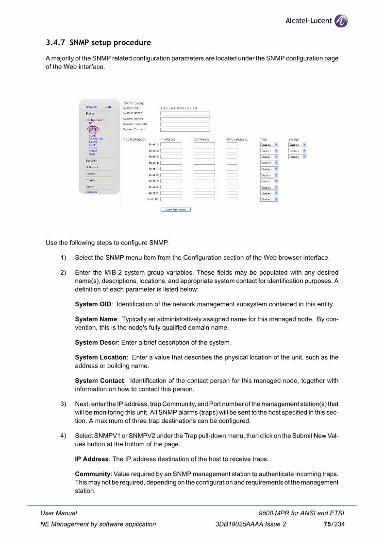
3.4.7 SNMP setup procedure
A majority of the SNMP related configuration parameters are located under the SNMP configuration pageof the Web interface.
Use the following steps to configure SNMP.
1) Select the SNMP menu item from the Configuration section of the Web browser interface.
2) Enter the MIB-2 system group variables. These fields may be populated with any desiredname(s), descriptions, locations, and appropriate system contact for identification purposes. Adefinition of each parameter is listed below:
System OID: Identification of the network management subsystem contained in this entity.
System Name: Typically an administratively assigned name for this managed node. By con-vention, this is the node's fully qualified domain name.
System Descr: Enter a brief description of the system.
System Location: Enter a value that describes the physical location of the unit, such as theaddress or building name.
System Contact: Identification of the contact person for this managed node, together withinformation on how to contact this person.
3) Next, enter the IP address, trap Community, and Port number of the management station(s) thatwill be monitoring this unit. All SNMP alarms (traps) will be sent to the host specified in this sec-tion. A maximum of three trap destinations can be configured.
4) Select SNMPV1 or SNMPV2 under the Trap pull-down menu, then click on the Submit New Val-ues button at the bottom of the page.
IP Address: The IP address destination of the host to receive traps.
Community: Value required by an SNMP management station to authenticate incoming traps.This may not be required, depending on the configuration and requirements of the managementstation.
User Manual
NE Management by software application
9500 MPR for ANSI and ETSI
3DB19025AAAA Issue 2 75/234
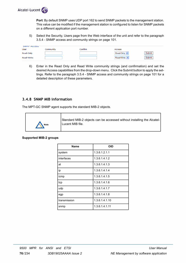
Port: By default SNMP uses UDP port 162 to send SNMP packets to the management station.This value can be modified if the management station is configured to listen for SNMP packetson a different application port number.
5) Select the Security, Users page from the Web interface of the unit and refer to the paragraph3.5.4 - SNMP access and community strings on page 101.
6) Enter in the Read Only and Read Write community strings (and confirmation) and set thedesired Access capabilities from the drop-down menu. Click the Submit button to apply the set-tings. Refer to the paragraph 3.5.4 - SNMP access and community strings on page 101 for adetailed description of these parameters.
3.4.8 SNMP MIB information
The MPT-GC SNMP agent supports the standard MIB-2 objects.
Supported MIB-2 groups
Standard MIB-2 objects can be accessed without installing the Alcatel-Lucent MIB file.
Name OID
system 1.3.6.1.2.1.1
interfaces 1.3.6.1.4.1.2
at 1.3.6.1.4.1.3
ip 1.3.6.1.4.1.4
icmp 1.3.6.1.4.1.5
tcp 1.3.6.1.4.1.6
udp 1.3.6.1.4.1.7
egp 1.3.6.1.4.1.8
transmission 1.3.6.1.4.1.10
snmp 1.3.6.1.4.1.11
User Manual
NE Management by software application
9500 MPR for ANSI and ETSI
3DB19025AAAA Issue 276/234
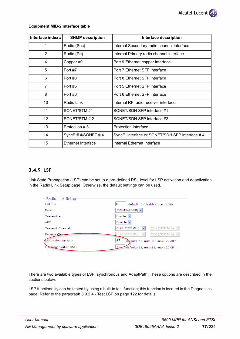
Equipment MIB-2 interface table
3.4.9 LSP
Link State Propagation (LSP) can be set to a pre-defined RSL level for LSP activation and deactivationin the Radio Link Setup page. Otherwise, the default settings can be used.
There are two available types of LSP: synchronous and AdaptPath. These options are described in thesections below.
LSP functionality can be tested by using a built-in test function; this function is located in the Diagnosticspage. Refer to the paragraph 3.9.2.4 - Test LSP on page 122 for details.
Interface index # SNMP description Interface description
1 Radio (Sec) Internal Secondary radio channel interface
2 Radio (Pri) Internal Primary radio channel interface
4 Copper #9 Port 9 Ethernet copper interface
5 Port #7 Port 7 Ethernet SFP interface
6 Port #8 Port 8 Ethernet SFP interface
7 Port #5 Port 5 Ethernet SFP interface
8 Port #6 Port 6 Ethernet SFP interface
10 Radio Link Internal RF radio receiver interface
11 SONET/STM #1 SONET/SDH SFP interface #1
12 SONET/STM # 2 SONET/SDH SFP interface #2
13 Protection # 3 Protection interface
14 SyncE # 4/SONET # 4 SyncE interface or SONET/SDH SFP interface # 4
15 Ethernet Interface Internal Ethernet Interface
User Manual
NE Management by software application
9500 MPR for ANSI and ETSI
3DB19025AAAA Issue 2 77/234
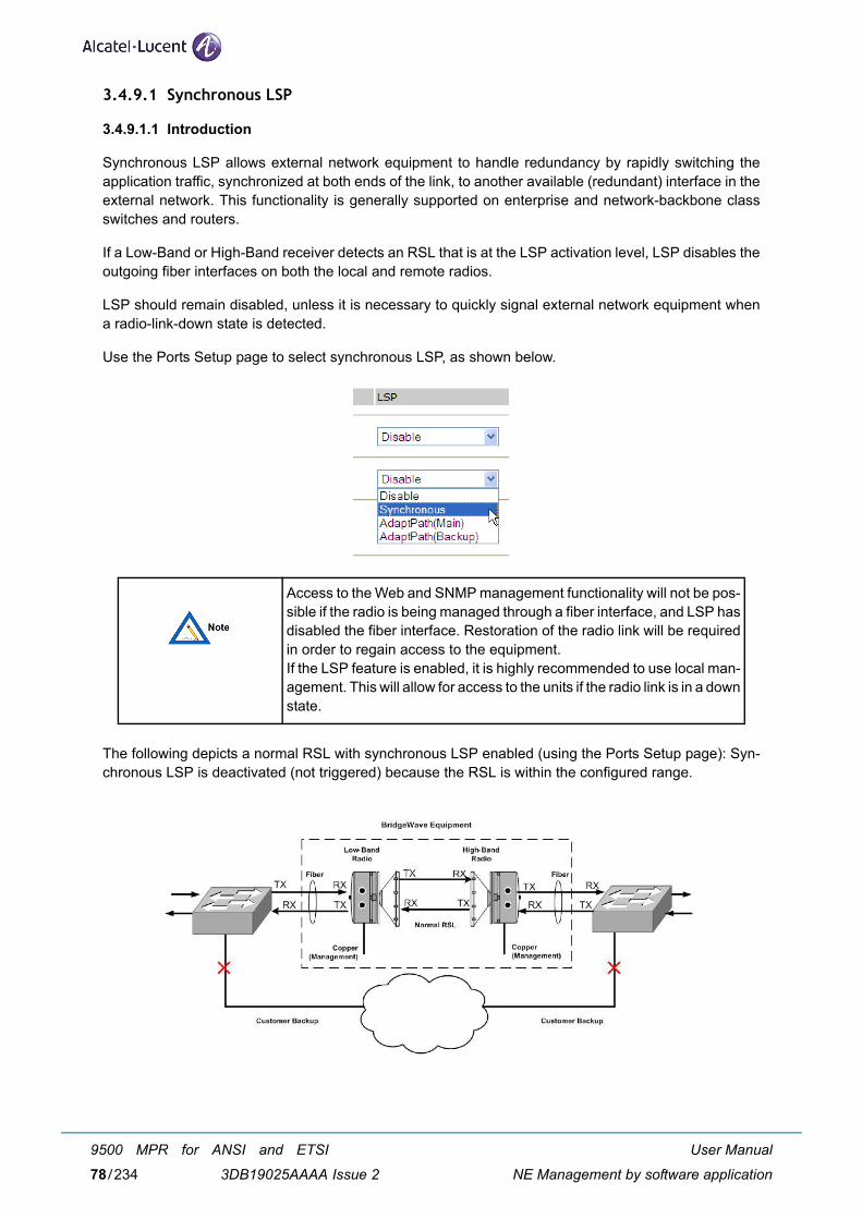
3.4.9.1 Synchronous LSP
3.4.9.1.1 Introduction
Synchronous LSP allows external network equipment to handle redundancy by rapidly switching theapplication traffic, synchronized at both ends of the link, to another available (redundant) interface in theexternal network. This functionality is generally supported on enterprise and network-backbone classswitches and routers.
If a Low-Band or High-Band receiver detects an RSL that is at the LSP activation level, LSP disables theoutgoing fiber interfaces on both the local and remote radios.
LSP should remain disabled, unless it is necessary to quickly signal external network equipment whena radio-link-down state is detected.
Use the Ports Setup page to select synchronous LSP, as shown below.
The following depicts a normal RSL with synchronous LSP enabled (using the Ports Setup page): Syn-chronous LSP is deactivated (not triggered) because the RSL is within the configured range.
Access to the Web and SNMP management functionality will not be pos-sible if the radio is being managed through a fiber interface, and LSP hasdisabled the fiber interface. Restoration of the radio link will be requiredin order to regain access to the equipment. If the LSP feature is enabled, it is highly recommended to use local man-agement. This will allow for access to the units if the radio link is in a downstate.
User Manual
NE Management by software application
9500 MPR for ANSI and ETSI
3DB19025AAAA Issue 278/234
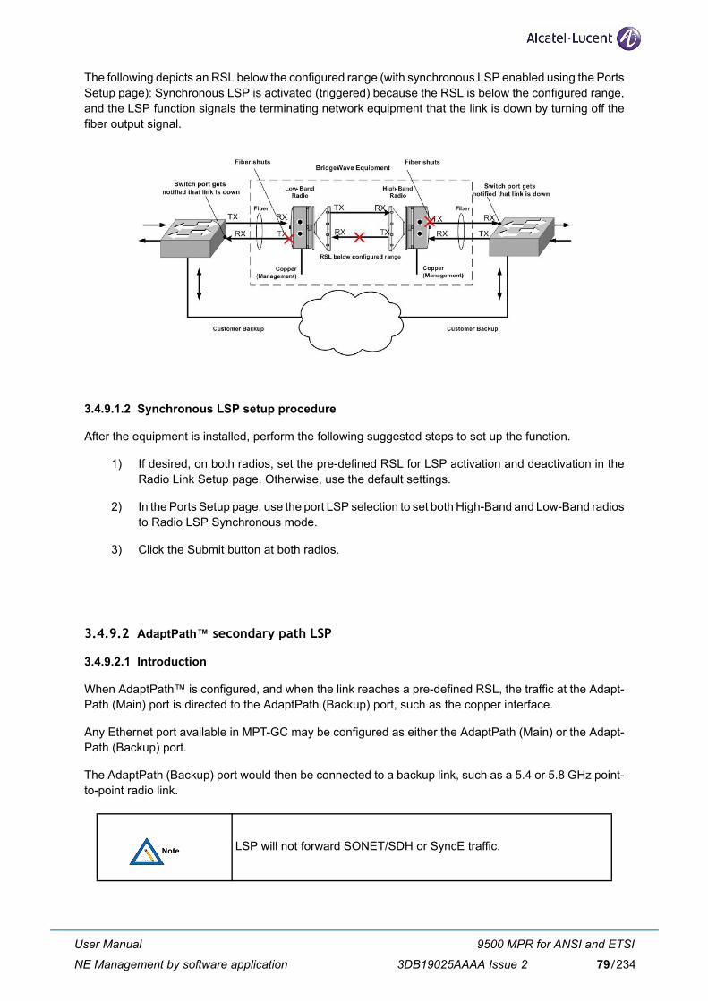
The following depicts an RSL below the configured range (with synchronous LSP enabled using the PortsSetup page): Synchronous LSP is activated (triggered) because the RSL is below the configured range,and the LSP function signals the terminating network equipment that the link is down by turning off thefiber output signal.
3.4.9.1.2 Synchronous LSP setup procedure
After the equipment is installed, perform the following suggested steps to set up the function.
1) If desired, on both radios, set the pre-defined RSL for LSP activation and deactivation in theRadio Link Setup page. Otherwise, use the default settings.
2) In the Ports Setup page, use the port LSP selection to set both High-Band and Low-Band radiosto Radio LSP Synchronous mode.
3) Click the Submit button at both radios.
3.4.9.2 AdaptPath™ secondary path LSP
3.4.9.2.1 Introduction
When AdaptPath™ is configured, and when the link reaches a pre-defined RSL, the traffic at the Adapt-Path (Main) port is directed to the AdaptPath (Backup) port, such as the copper interface.
Any Ethernet port available in MPT-GC may be configured as either the AdaptPath (Main) or the Adapt-Path (Backup) port.
The AdaptPath (Backup) port would then be connected to a backup link, such as a 5.4 or 5.8 GHz point-to-point radio link.
LSP will not forward SONET/SDH or SyncE traffic.
User Manual
NE Management by software application
9500 MPR for ANSI and ETSI
3DB19025AAAA Issue 2 79/234
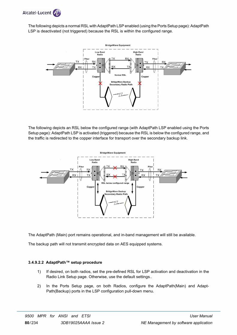
The following depicts a normal RSL with AdaptPath LSP enabled (using the Ports Setup page): AdaptPathLSP is deactivated (not triggered) because the RSL is within the configured range.
The following depicts an RSL below the configured range (with AdaptPath LSP enabled using the PortsSetup page): AdaptPath LSP is activated (triggered) because the RSL is below the configured range, andthe traffic is redirected to the copper interface for transport over the secondary backup link.
The AdaptPath (Main) port remains operational, and in-band management will still be available.
The backup path will not transmit encrypted data on AES equipped systems.
3.4.9.2.2 AdaptPath™ setup procedure
1) If desired, on both radios, set the pre-defined RSL for LSP activation and deactivation in theRadio Link Setup page. Otherwise, use the default settings..
2) In the Ports Setup page, on both Radios, configure the AdaptPath(Main) and Adapt-Path(Backup) ports in the LSP configuration pull-down menu.
User Manual
NE Management by software application
9500 MPR for ANSI and ETSI
3DB19025AAAA Issue 280/234
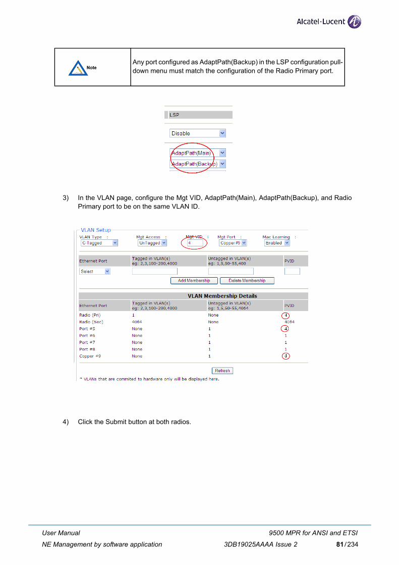
3) In the VLAN page, configure the Mgt VID, AdaptPath(Main), AdaptPath(Backup), and RadioPrimary port to be on the same VLAN ID.
4) Click the Submit button at both radios.
Any port configured as AdaptPath(Backup) in the LSP configuration pull-down menu must match the configuration of the Radio Primary port.
User Manual
NE Management by software application
9500 MPR for ANSI and ETSI
3DB19025AAAA Issue 2 81/234
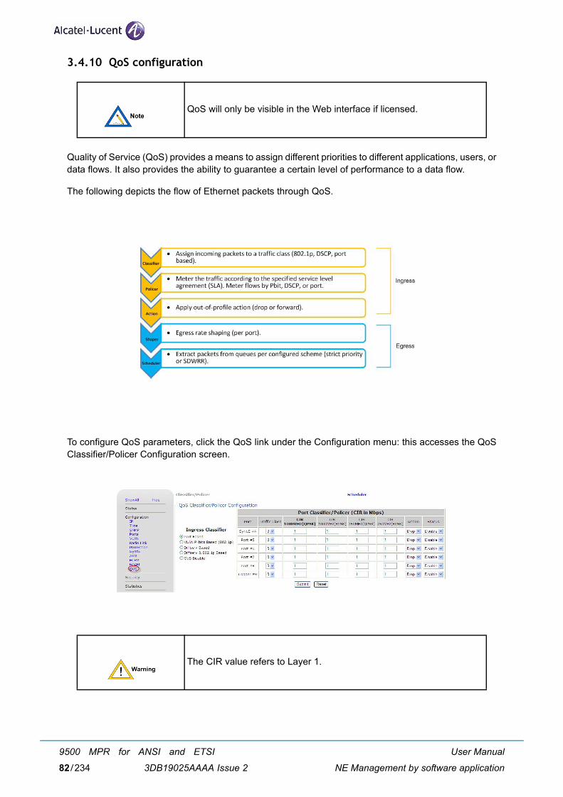
3.4.10 QoS configuration
Quality of Service (QoS) provides a means to assign different priorities to different applications, users, ordata flows. It also provides the ability to guarantee a certain level of performance to a data flow.
The following depicts the flow of Ethernet packets through QoS.
To configure QoS parameters, click the QoS link under the Configuration menu: this accesses the QoSClassifier/Policer Configuration screen.
QoS will only be visible in the Web interface if licensed.
The CIR value refers to Layer 1.
User Manual
NE Management by software application
9500 MPR for ANSI and ETSI
3DB19025AAAA Issue 282/234
3.4.10.1 QoS configuration overview
Configuring QoS parameters involves the following:
1) Set the priorities for the incoming packets using the QoS Classifier/Policer screens. The pri-orities range from 0-7, 7 being the highest priority.
2) Set the Committed Information Rate (CIR) for the port, Pbit, or DSCP; and whether to drop orforward packets exceeding the CIR using the QoS Classifier/Policer screens. If packets are setto be forwarded, the metering mechanism will be bypassed.
3) Enable or disable CIR for the port, Pbit, or DSCP using the Status menu.
4) Set the priority in which the packets are taken from the queues using the QoS Scheduler Con-figuration screens. The priorities range from 0-7, 7 being the highest priority.
The Submit and Reset buttons are common to all QoS Configuration screens.
– Submit - Use the Submit button to set the values.
– Reset - Use the Reset button to set the parameters to the default value.
3.4.10.2 QoS classifier/policer configuration
3.4.10.2.1 overview
Use the QoS Classifier/Policer Configuration screen to:
– set the priority of incoming (ingress) packets;
– set the Committed Information Rate (CIR), in Mbps, for the port, Pbit, or DSCP;
– drop or forward packets exceeding the CIR;
– enable or disable CIR on the port, Pbit, or DSCP;
– disable QoS.
Before configuring QoS, the ports should be up.
Any port configured as AdaptPath(Backup) in the LSP configuration pull-down menu must match the QoS configuration of the radio primary port.
Any port configured as AdaptPath(Backup) in the LSP configuration pull-down menu must match the QoS configuration of the radio primary port.
User Manual
NE Management by software application
9500 MPR for ANSI and ETSI
3DB19025AAAA Issue 2 83/234
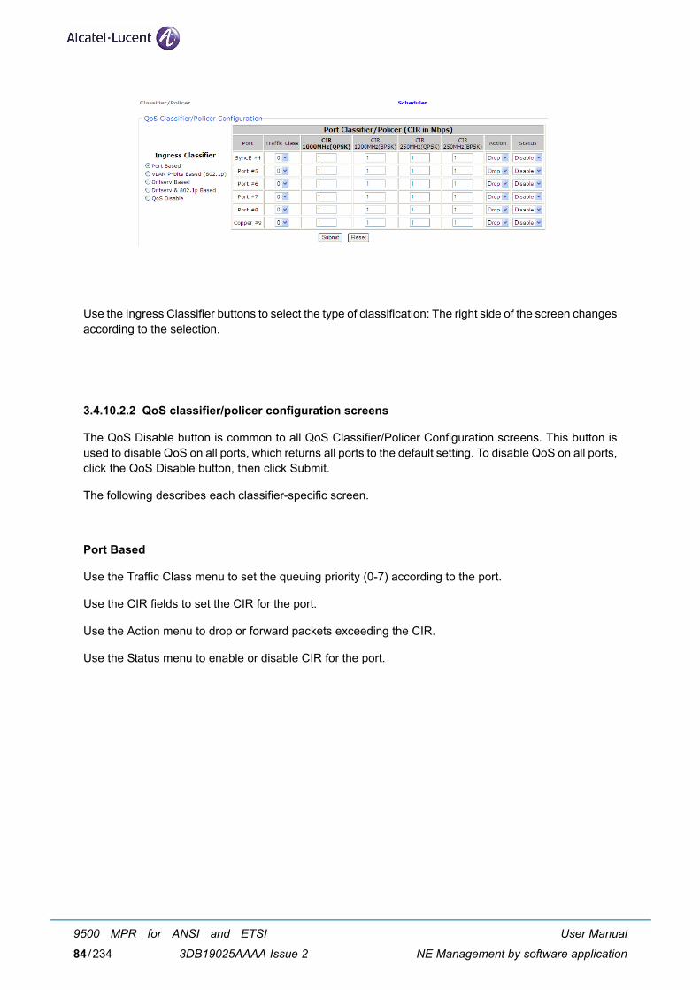
Use the Ingress Classifier buttons to select the type of classification: The right side of the screen changesaccording to the selection.
3.4.10.2.2 QoS classifier/policer configuration screens
The QoS Disable button is common to all QoS Classifier/Policer Configuration screens. This button isused to disable QoS on all ports, which returns all ports to the default setting. To disable QoS on all ports,click the QoS Disable button, then click Submit.
The following describes each classifier-specific screen.
Port Based
Use the Traffic Class menu to set the queuing priority (0-7) according to the port.
Use the CIR fields to set the CIR for the port.
Use the Action menu to drop or forward packets exceeding the CIR.
Use the Status menu to enable or disable CIR for the port.
User Manual
NE Management by software application
9500 MPR for ANSI and ETSI
3DB19025AAAA Issue 284/234
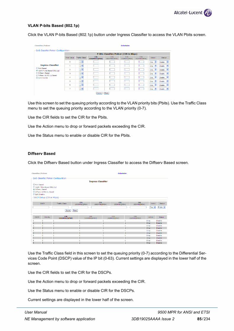
VLAN P-bits Based (802.1p)
Click the VLAN P-bits Based (802.1p) button under Ingress Classifier to access the VLAN Pbits screen.
Use this screen to set the queuing priority according to the VLAN priority bits (Pbits). Use the Traffic Classmenu to set the queuing priority according to the VLAN priority (0-7).
Use the CIR fields to set the CIR for the Pbits.
Use the Action menu to drop or forward packets exceeding the CIR.
Use the Status menu to enable or disable CIR for the Pbits.
Diffserv Based
Click the Diffserv Based button under Ingress Classifier to access the Diffserv Based screen.
Use the Traffic Class field in this screen to set the queuing priority (0-7) according to the Differential Ser-vices Code Point (DSCP) value of the IP bit (0-63). Current settings are displayed in the lower half of thescreen.
Use the CIR fields to set the CIR for the DSCPs.
Use the Action menu to drop or forward packets exceeding the CIR.
Use the Status menu to enable or disable CIR for the DSCPs.
Current settings are displayed in the lower half of the screen.
User Manual
NE Management by software application
9500 MPR for ANSI and ETSI
3DB19025AAAA Issue 2 85/234
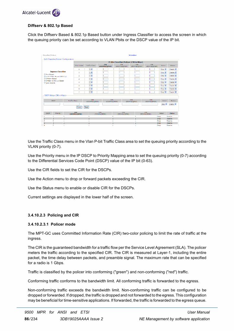
Diffserv & 802.1p Based
Click the Diffserv Based & 802.1p Based button under Ingress Classifier to access the screen in whichthe queuing priority can be set according to VLAN Pbits or the DSCP value of the IP bit.
Use the Traffic Class menu in the Vlan P-bit Traffic Class area to set the queuing priority according to theVLAN priority (0-7).
Use the Priority menu in the IP DSCP to Priority Mapping area to set the queuing priority (0-7) accordingto the Differential Services Code Point (DSCP) value of the IP bit (0-63).
Use the CIR fields to set the CIR for the DSCPs.
Use the Action menu to drop or forward packets exceeding the CIR.
Use the Status menu to enable or disable CIR for the DSCPs.
Current settings are displayed in the lower half of the screen.
3.4.10.2.3 Policing and CIR
3.4.10.2.3.1 Policer mode
The MPT-GC uses Committed Information Rate (CIR) two-color policing to limit the rate of traffic at theingress.
The CIR is the guaranteed bandwidth for a traffic flow per the Service Level Agreement (SLA). The policermeters the traffic according to the specified CIR. The CIR is measured at Layer-1, including the entirepacket, the time delay between packets, and preamble signal. The maximum rate that can be specifiedfor a radio is 1 Gbps.
Traffic is classified by the policer into conforming ("green") and non-conforming ("red") traffic.
Conforming traffic conforms to the bandwidth limit. All conforming traffic is forwarded to the egress.
Non-conforming traffic exceeds the bandwidth limit. Non-conforming traffic can be configured to bedropped or forwarded. If dropped, the traffic is dropped and not forwarded to the egress. This configurationmay be beneficial for time-sensitive applications. If forwarded, the traffic is forwarded to the egress queue.
User Manual
NE Management by software application
9500 MPR for ANSI and ETSI
3DB19025AAAA Issue 286/234
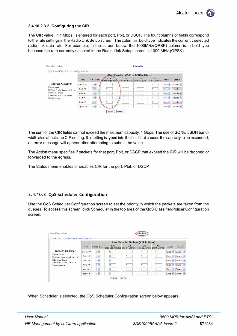
3.4.10.2.3.2 Configuring the CIR
The CIR value, in 1 Mbps, is entered for each port, Pbit, or DSCP. The four columns of fields correspondto the rate settings in the Radio Link Setup screen. The column in bold type indicates the currently selectedradio link data rate. For example, in the screen below, the 1000MHz(QPSK) column is in bold typebecause the rate currently selected in the Radio Link Setup screen is 1000 MHz (QPSK).
The sum of the CIR fields cannot exceed the maximum capacity, 1 Gbps. The use of SONET/SDH band-width also affects the CIR setting. If a setting is typed into the field that causes the capacity to be exceeded,an error message will appear after attempting to submit the value.
The Action menu specifies if packets for that port, Pbit, or DSCP that exceed the CIR will be dropped orforwarded to the egress.
The Status menu enables or disables CIR for the port, Pbit, or DSCP.
3.4.10.3 QoS Scheduler Configuration
Use the QoS Scheduler Configuration screen to set the priority in which the packets are taken from thequeues. To access this screen, click Scheduler in the top area of the QoS Classifier/Policer Configurationscreen.
When Scheduler is selected, the QoS Scheduler Configuration screen below appears.
User Manual
NE Management by software application
9500 MPR for ANSI and ETSI
3DB19025AAAA Issue 2 87/234
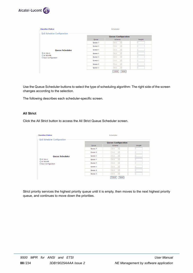
Use the Queue Scheduler buttons to select the type of scheduling algorithm: The right side of the screenchanges according to the selection.
The following describes each scheduler-specific screen.
All Strict
Click the All Strict button to access the All Strict Queue Scheduler screen.
Strict priority services the highest priority queue until it is empty, then moves to the next highest priorityqueue, and continues to move down the priorities.
User Manual
NE Management by software application
9500 MPR for ANSI and ETSI
3DB19025AAAA Issue 288/234
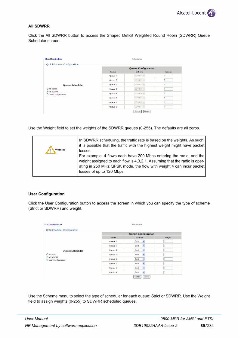
All SDWRR
Click the All SDWRR button to access the Shaped Deficit Weighted Round Robin (SDWRR) QueueScheduler screen.
Use the Weight field to set the weights of the SDWRR queues (0-255). The defaults are all zeros.
User Configuration
Click the User Configuration button to access the screen in which you can specify the type of scheme(Strict or SDWRR) and weight.
Use the Scheme menu to select the type of scheduler for each queue: Strict or SDWRR. Use the Weightfield to assign weights (0-255) to SDWRR scheduled queues.
In SDWRR scheduling, the traffic rate is based on the weights. As such,it is possible that the traffic with the highest weight might have packetlosses.For example: 4 flows each have 200 Mbps entering the radio, and theweight assigned to each flow is 4,3,2,1. Assuming that the radio is oper-ating in 250 MHz QPSK mode, the flow with weight 4 can incur packetlosses of up to 120 Mbps.
User Manual
NE Management by software application
9500 MPR for ANSI and ETSI
3DB19025AAAA Issue 2 89/234

3.4.10.4 QoS configuration example
In the following example, a customer has three services assigned the following bit rates and priorities:
– Video with a 400 Mbps rate with the highest priority
– Voice with a 150 Mbps rate with the next-highest priority
– Data with a 100 Mbps rate with the lowest priority
The priority of incoming packets for the above scenario could be set in the port-based Classifier/PolicerConfiguration screen as shown below:
– Port #5 is assigned video with a traffic class of 6 and a CIR of 400.
– Port #6 is assigned voice with a traffic class of 4 and a CIR of 150.
– Port #7 is assigned data with a traffic class of 2 and a CIR of 100.
– All packets exceeding the CIR in these ports are set to be dropped.
– CIR is enabled on these ports.
If the radio degrades from 1200 mode to 600 mode (assuming ARM is enabled), then the highest prioritytraffic (video) will remain unaffected. Considering the remaining bandwidth, the second and third prioritytraffic will pass through, or be dropped. In this example, the voice traffic will pass through, but 50 Mbpsof the data traffic will be dropped, because the other services have consumed the radio pipe.
User Manual
NE Management by software application
9500 MPR for ANSI and ETSI
3DB19025AAAA Issue 290/234
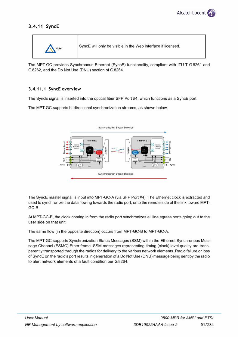
3.4.11 SyncE
The MPT-GC provides Synchronous Ethernet (SyncE) functionality, compliant with ITU-T G.8261 andG.8262, and the Do Not Use (DNU) section of G.8264.
3.4.11.1 SyncE overview
The SyncE signal is inserted into the optical fiber SFP Port #4, which functions as a SyncE port.
The MPT-GC supports bi-directional synchronization streams, as shown below.
The SyncE master signal is input into MPT-GC-A (via SFP Port #4). The Ethernet clock is extracted andused to synchronize the data flowing towards the radio port, onto the remote side of the link toward MPT-GC-B.
At MPT-GC-B, the clock coming in from the radio port synchronizes all line egress ports going out to theuser side on that unit.
The same flow (in the opposite direction) occurs from MPT-GC-B to MPT-GC-A.
The MPT-GC supports Synchronization Status Messages (SSM) within the Ethernet Synchronous Mes-sage Channel (ESMC) Ether frame. SSM messages representing timing (clock) level quality are trans-parently transported through the radios for delivery to the various network elements. Radio failure or lossof SyncE on the radio's port results in generation of a Do Not Use (DNU) message being sent by the radioto alert network elements of a fault condition per G.8264.
SyncE will only be visible in the Web interface if licensed.
User Manual
NE Management by software application
9500 MPR for ANSI and ETSI
3DB19025AAAA Issue 2 91/234
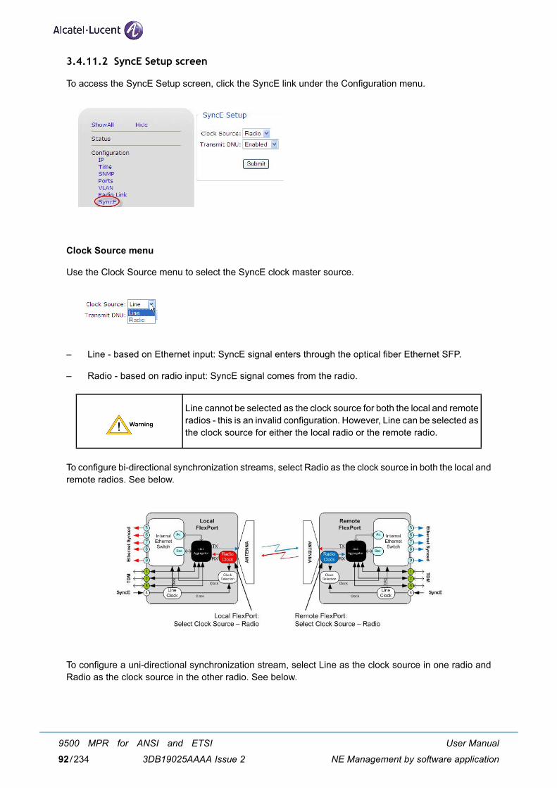
3.4.11.2 SyncE Setup screen
To access the SyncE Setup screen, click the SyncE link under the Configuration menu.
Clock Source menu
Use the Clock Source menu to select the SyncE clock master source.
– Line - based on Ethernet input: SyncE signal enters through the optical fiber Ethernet SFP.
– Radio - based on radio input: SyncE signal comes from the radio.
To configure bi-directional synchronization streams, select Radio as the clock source in both the local andremote radios. See below.
To configure a uni-directional synchronization stream, select Line as the clock source in one radio andRadio as the clock source in the other radio. See below.
Line cannot be selected as the clock source for both the local and remoteradios - this is an invalid configuration. However, Line can be selected asthe clock source for either the local radio or the remote radio.
User Manual
NE Management by software application
9500 MPR for ANSI and ETSI
3DB19025AAAA Issue 292/234
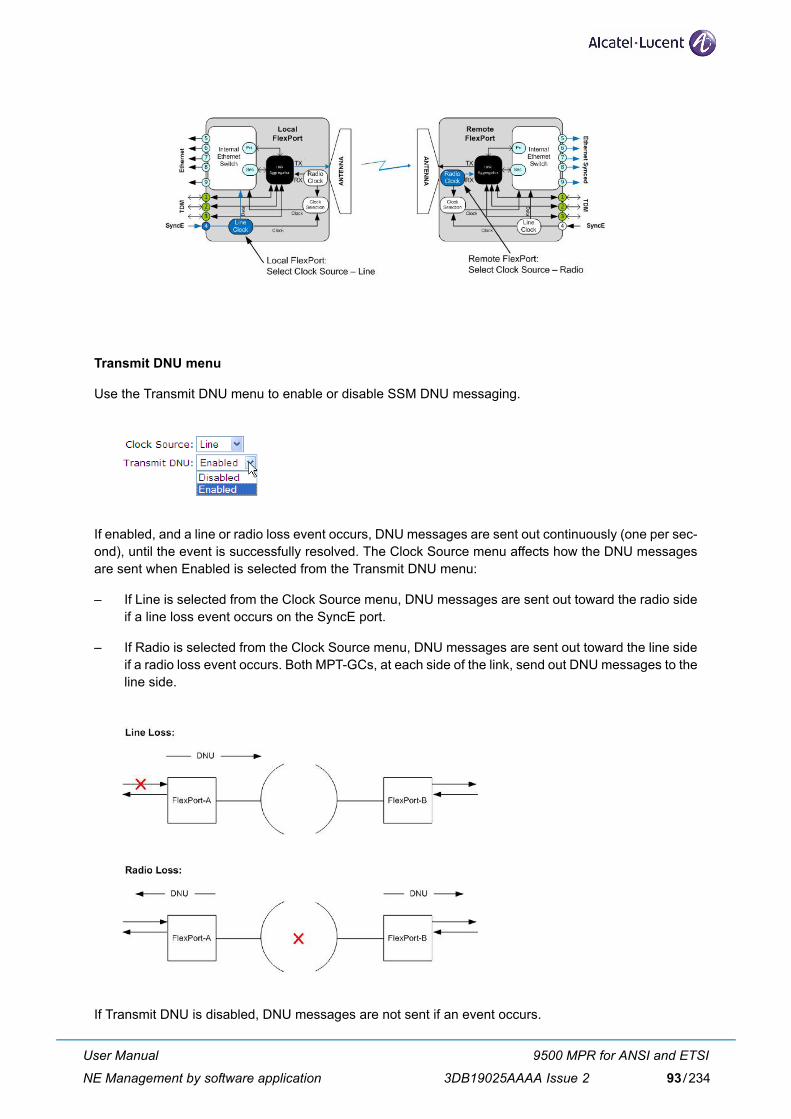
Transmit DNU menu
Use the Transmit DNU menu to enable or disable SSM DNU messaging.
If enabled, and a line or radio loss event occurs, DNU messages are sent out continuously (one per sec-ond), until the event is successfully resolved. The Clock Source menu affects how the DNU messagesare sent when Enabled is selected from the Transmit DNU menu:
– If Line is selected from the Clock Source menu, DNU messages are sent out toward the radio sideif a line loss event occurs on the SyncE port.
– If Radio is selected from the Clock Source menu, DNU messages are sent out toward the line sideif a radio loss event occurs. Both MPT-GCs, at each side of the link, send out DNU messages to theline side.
If Transmit DNU is disabled, DNU messages are not sent if an event occurs.
User Manual
NE Management by software application
9500 MPR for ANSI and ETSI
3DB19025AAAA Issue 2 93/234
3.4.12 1+1 Hot Standby Protection
1+1 Hot Standby Protection (also called Protection) provides system redundancy that will take effect whena failure is detected: this ensures system-level mitigation of local hardware problems.
3.4.12.1 Overview
Protection consists of a mated pair of radios on each side of the link, backing each other up. Each sidehas an active and standby radio. Ideally, the active radio is the main radio (with maximum 3 dB loss), thatis, the preferred radio to carry data. The standby radio (with maximum 11 dB loss) acts as a backup radiothat will take control if the active radio fails to carry traffic. The radios are locally interconnected to shareProtection-related information. Only the active radio transmits to the link and to the line. Switching is donebetween the active and standby radios on each side of the link, independent of the remote side. The Pro-tection mode menu in the Protection screen is used to designate the radio as active or standby.
Protection switching is based on the following, in order of priority:
– Mate power off - when a radio detects the mate radio's power is off, it initiates a Protection switch.
– Lockout - configured by the user for maintenance purposes. This overrides the Protection decisionmaking and locks the radio in its current mode, until the user disables Lockout.
– Force Switch - configured by the user for maintenance purposes. This forces the radio to performa Protection switch, and then be locked in that mode, until the user disables Force Switch.
– Radio Loss of Frame (RLOF) - when the active radio detects an RLOF, it initiates a Protection switch.
– Line Loss of Signal (LOS)/Line Loss of Carrier (LOC) - when the active radio detects an LOS/LOC,it initiates a Protection switch.
– Manual Switch - configured by the user to request an active radio to switch to standby. The activeradio complies if there are no registered faults on the standby radio. Switches are performed inde-pendently on each side of the link.
One hardware failure is handled at a time; fading of the radio link is not handled.
Protection switches will yield no more than 50 ms of traffic disruption.
1+1 Hot Standby Protection will only be visible in the Web interface iflicensed.
Pay attention to the optical cable plug TX and RX side to avoid Ethernetloop.
For Protection systems, software upgrades must be performed on thestandby radio.
User Manual
NE Management by software application
9500 MPR for ANSI and ETSI
3DB19025AAAA Issue 294/234
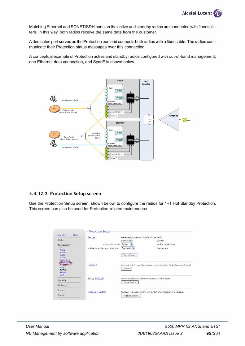
Matching Ethernet and SONET/SDH ports on the active and standby radios are connected with fiber split-ters. In this way, both radios receive the same data from the customer.
A dedicated port serves as the Protection port and connects both radios with a fiber cable. The radios com-municate their Protection status messages over this connection.
A conceptual example of Protection active and standby radios configured with out-of-band management,one Ethernet data connection, and SyncE is shown below.
3.4.12.2 Protection Setup screen
Use the Protection Setup screen, shown below, to configure the radios for 1+1 Hot Standby Protection.This screen can also be used for Protection-related maintenance.
User Manual
NE Management by software application
9500 MPR for ANSI and ETSI
3DB19025AAAA Issue 2 95/234
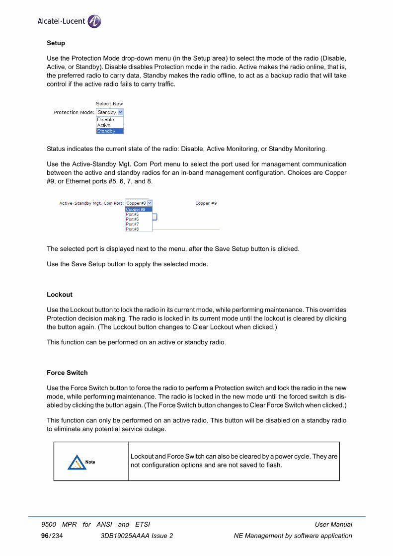
Setup
Use the Protection Mode drop-down menu (in the Setup area) to select the mode of the radio (Disable,Active, or Standby). Disable disables Protection mode in the radio. Active makes the radio online, that is,the preferred radio to carry data. Standby makes the radio offline, to act as a backup radio that will takecontrol if the active radio fails to carry traffic.
Status indicates the current state of the radio: Disable, Active Monitoring, or Standby Monitoring.
Use the Active-Standby Mgt. Com Port menu to select the port used for management communicationbetween the active and standby radios for an in-band management configuration. Choices are Copper#9, or Ethernet ports #5, 6, 7, and 8.
The selected port is displayed next to the menu, after the Save Setup button is clicked.
Use the Save Setup button to apply the selected mode.
Lockout
Use the Lockout button to lock the radio in its current mode, while performing maintenance. This overridesProtection decision making. The radio is locked in its current mode until the lockout is cleared by clickingthe button again. (The Lockout button changes to Clear Lockout when clicked.)
This function can be performed on an active or standby radio.
Force Switch
Use the Force Switch button to force the radio to perform a Protection switch and lock the radio in the newmode, while performing maintenance. The radio is locked in the new mode until the forced switch is dis-abled by clicking the button again. (The Force Switch button changes to Clear Force Switch when clicked.)
This function can only be performed on an active radio. This button will be disabled on a standby radioto eliminate any potential service outage.
Lockout and Force Switch can also be cleared by a power cycle. They arenot configuration options and are not saved to flash.
User Manual
NE Management by software application
9500 MPR for ANSI and ETSI
3DB19025AAAA Issue 296/234
Manual Switch
Use the Manual Switch button to manually switch the active radio to standby mode. The switch will occuronly if there are no registered faults on the standby radio.
This function can only be performed on an active radio. This button will be disabled on a standby radio.
3.4.12.3 Configuration sequence
The active and standby radios must be configured identically on each side of the link. The basic config-uration sequence is as follows:
1) Configure the active (main) radio.
2) Configure the standby radio the same as the active radio.
3) Configure the active (main) radio as active: Select Active from the Setup Protection Mode drop-down menu.
4) If using an in-band management configuration, select the port to be used for management com-munication between the active and standby radios from the Active-Standby Mgt. Com Portdrop-down menu.
5) Click Save Setup.
6) Configure the standby radio as standby: Select Standby from the Setup Protection Mode drop-down menu.
7) If using an in-band management configuration, select the port to be used for management com-munication between the active and standby radios from the Active-Standby Mgt. Com Portdrop-down menu. This port should be the same one as selected in the active radio.
8) Click Save Setup.
When Protection is enabled, ensure the LSP AdaptPath, ARM, andAdaptRate options are disabled. If LSP AdaptPath was configured beforeProtection was enabled, the LSP AdaptPath configuration will remain inthe radio database, but will be disabled. When Protection is disabled,LSP AdaptPath, ARM, and AdaptRate will be operable.
As an alternative to manually configuring the standby radio identically,the configuration from the active radio can be backed up and imported tothe standby radio using the Traffic Configuration and System Configura-tion buttons in the Backup section of the Web interface Maintenancemenu. For details, refer to the paragraph 3.9.1.2 - Configuration filebackup on page 114.
All four radios must have the same AES key configured. Otherwise, trafficwill not flow over the link when switching to the standby. The keys aremanually entered and do not change.
User Manual
NE Management by software application
9500 MPR for ANSI and ETSI
3DB19025AAAA Issue 2 97/234
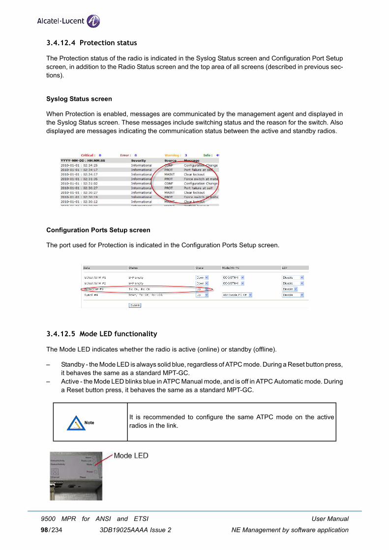
3.4.12.4 Protection status
The Protection status of the radio is indicated in the Syslog Status screen and Configuration Port Setupscreen, in addition to the Radio Status screen and the top area of all screens (described in previous sec-tions).
Syslog Status screen
When Protection is enabled, messages are communicated by the management agent and displayed inthe Syslog Status screen. These messages include switching status and the reason for the switch. Alsodisplayed are messages indicating the communication status between the active and standby radios.
Configuration Ports Setup screen
The port used for Protection is indicated in the Configuration Ports Setup screen.
3.4.12.5 Mode LED functionality
The Mode LED indicates whether the radio is active (online) or standby (offline).
– Standby - the Mode LED is always solid blue, regardless of ATPC mode. During a Reset button press,it behaves the same as a standard MPT-GC.
– Active - the Mode LED blinks blue in ATPC Manual mode, and is off in ATPC Automatic mode. Duringa Reset button press, it behaves the same as a standard MPT-GC.
It is recommended to configure the same ATPC mode on the activeradios in the link.
User Manual
NE Management by software application
9500 MPR for ANSI and ETSI
3DB19025AAAA Issue 298/234
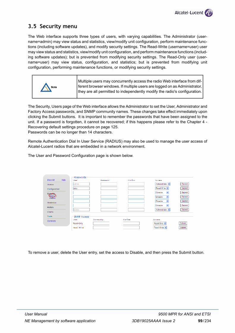
3.5 Security menu
The Web interface supports three types of users, with varying capabilities. The Administrator (user-name=admin) may view status and statistics, view/modify unit configuration, perform maintenance func-tions (including software updates), and modify security settings. The Read-Write (username=user) usermay view status and statistics, view/modify unit configuration, and perform maintenance functions (includ-ing software updates); but is prevented from modifying security settings. The Read-Only user (user-name=user) may view status, configuration, and statistics; but is prevented from modifying unitconfiguration, performing maintenance functions, or modifying security settings.
The Security, Users page of the Web interface allows the Administrator to set the User, Administrator andFactory Access passwords, and SNMP community names. These changes take effect immediately uponclicking the Submit buttons. It is important to remember the passwords that have been assigned to theunit. If a password is forgotten, it cannot be recovered; if this happens please refer to the Chapter 4 -Recovering default settings procedure on page 125.Passwords can be no longer than 14 characters.
Remote Authentication Dial In User Service (RADIUS) may also be used to manage the user access ofAlcatel-Lucent radios that are embedded in a network environment.
The User and Password Configuration page is shown below.
To remove a user, delete the User entry, set the access to Disable, and then press the Submit button.
Multiple users may concurrently access the radio Web interface from dif-ferent browser windows. If multiple users are logged on as Administrator,they are all permitted to independently modify the radio's configuration.
User Manual
NE Management by software application
9500 MPR for ANSI and ETSI
3DB19025AAAA Issue 2 99/234
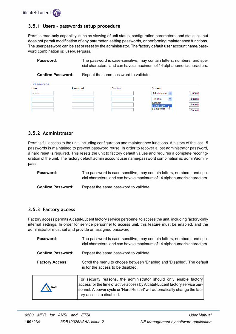
3.5.1 Users - passwords setup procedure
Permits read-only capability, such as viewing of unit status, configuration parameters, and statistics; butdoes not permit modification of any parameter, setting passwords, or performing maintenance functions.The user password can be set or reset by the administrator. The factory default user account name/pass-word combination is: user/userpass.
Password: The password is case-sensitive, may contain letters, numbers, and spe-cial characters, and can have a maximum of 14 alphanumeric characters.
Confirm Password: Repeat the same password to validate.
3.5.2 Administrator
Permits full access to the unit, including configuration and maintenance functions. A history of the last 15passwords is maintained to prevent password reuse. In order to recover a lost administrator password,a hard reset is required. This resets the unit to factory default values and requires a complete reconfig-uration of the unit. The factory default admin account user name/password combination is: admin/admin-pass.
Password: The password is case-sensitive, may contain letters, numbers, and spe-cial characters, and can have a maximum of 14 alphanumeric characters.
Confirm Password: Repeat the same password to validate.
3.5.3 Factory access
Factory access permits Alcatel-Lucent factory service personnel to access the unit, including factory-onlyinternal settings. In order for service personnel to access unit, this feature must be enabled, and theadministrator must set and provide an assigned password.
Password: The password is case-sensitive, may contain letters, numbers, and spe-cial characters, and can have a maximum of 14 alphanumeric characters.
Confirm Password: Repeat the same password to validate.
Factory Access: Scroll the menu to choose between 'Enabled and 'Disabled'. The defaultis for the access to be disabled.
For security reasons, the administrator should only enable factoryaccess for the time of active access by Alcatel-Lucent factory service per-sonnel. A power cycle or 'Hard Restart' will automatically change the fac-tory access to disabled.
User Manual
NE Management by software application
9500 MPR for ANSI and ETSI
3DB19025AAAA Issue 2100/234
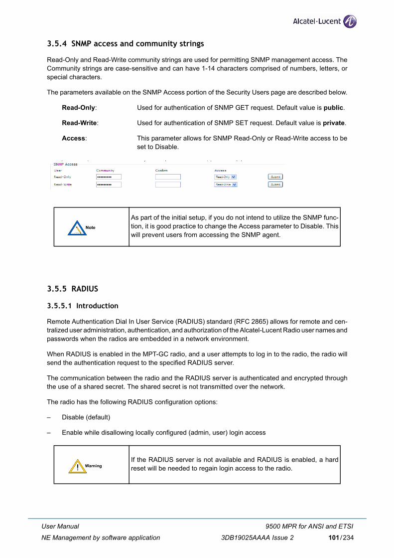
3.5.4 SNMP access and community strings
Read-Only and Read-Write community strings are used for permitting SNMP management access. TheCommunity strings are case-sensitive and can have 1-14 characters comprised of numbers, letters, orspecial characters.
The parameters available on the SNMP Access portion of the Security Users page are described below.
Read-Only: Used for authentication of SNMP GET request. Default value is public.
Read-Write: Used for authentication of SNMP SET request. Default value is private.
Access: This parameter allows for SNMP Read-Only or Read-Write access to beset to Disable.
3.5.5 RADIUS
3.5.5.1 Introduction
Remote Authentication Dial In User Service (RADIUS) standard (RFC 2865) allows for remote and cen-tralized user administration, authentication, and authorization of the Alcatel-Lucent Radio user names andpasswords when the radios are embedded in a network environment.
When RADIUS is enabled in the MPT-GC radio, and a user attempts to log in to the radio, the radio willsend the authentication request to the specified RADIUS server.
The communication between the radio and the RADIUS server is authenticated and encrypted throughthe use of a shared secret. The shared secret is not transmitted over the network.
The radio has the following RADIUS configuration options:
– Disable (default)
– Enable while disallowing locally configured (admin, user) login access
As part of the initial setup, if you do not intend to utilize the SNMP func-tion, it is good practice to change the Access parameter to Disable. Thiswill prevent users from accessing the SNMP agent.
If the RADIUS server is not available and RADIUS is enabled, a hardreset will be needed to regain login access to the radio.
User Manual
NE Management by software application
9500 MPR for ANSI and ETSI
3DB19025AAAA Issue 2 101/234
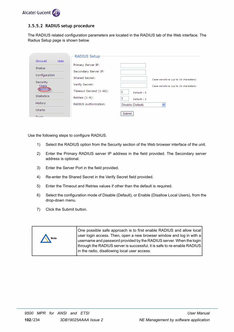
3.5.5.2 RADIUS setup procedure
The RADIUS related configuration parameters are located in the RADIUS tab of the Web interface. TheRadius Setup page is shown below.
Use the following steps to configure RADIUS.
1) Select the RADIUS option from the Security section of the Web browser interface of the unit.
2) Enter the Primary RADIUS server IP address in the field provided. The Secondary serveraddress is optional.
3) Enter the Server Port in the field provided.
4) Re-enter the Shared Secret in the Verify Secret field provided.
5) Enter the Timeout and Retries values if other than the default is required.
6) Select the configuration mode of Disable (Default), or Enable (Disallow Local Users), from thedrop-down menu.
7) Click the Submit button.
One possible safe approach is to first enable RADIUS and allow localuser login access. Then, open a new browser window and log in with ausername and password provided by the RADIUS server. When the loginthrough the RADIUS server is successful, it is safe to re-enable RADIUSin the radio, disallowing local user access.
User Manual
NE Management by software application
9500 MPR for ANSI and ETSI
3DB19025AAAA Issue 2102/234
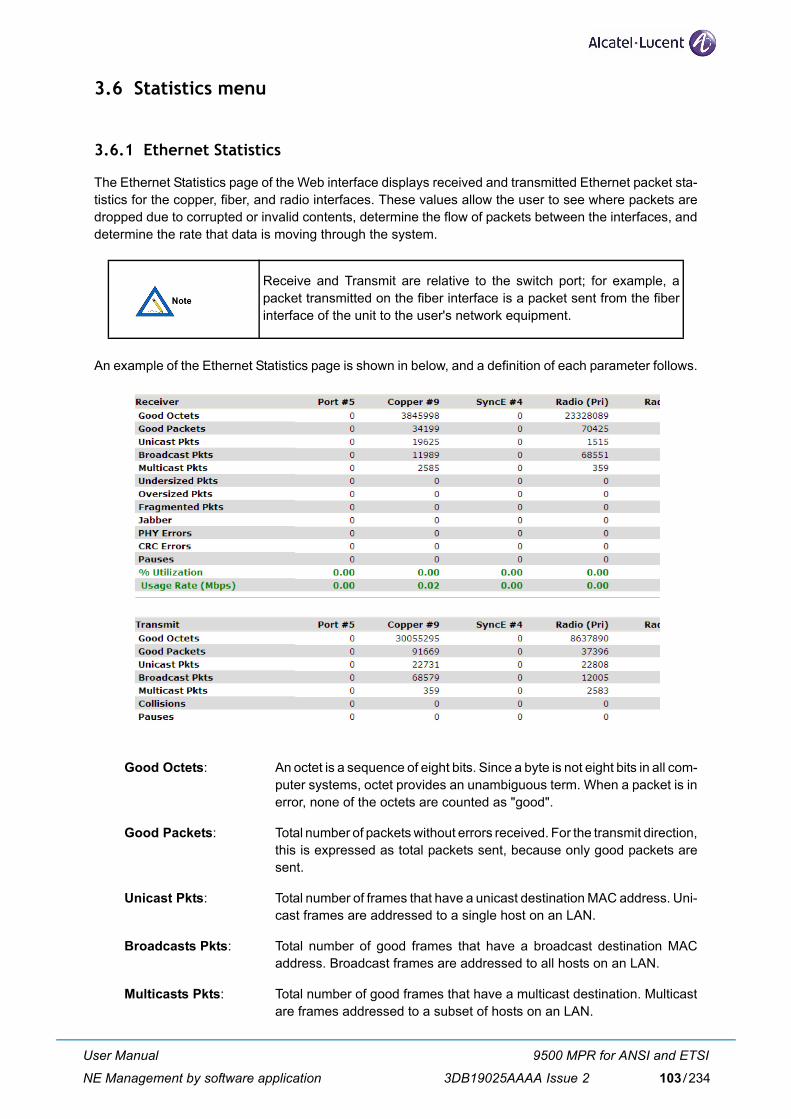
3.6 Statistics menu
3.6.1 Ethernet Statistics
The Ethernet Statistics page of the Web interface displays received and transmitted Ethernet packet sta-tistics for the copper, fiber, and radio interfaces. These values allow the user to see where packets aredropped due to corrupted or invalid contents, determine the flow of packets between the interfaces, anddetermine the rate that data is moving through the system.
An example of the Ethernet Statistics page is shown in below, and a definition of each parameter follows.
Good Octets: An octet is a sequence of eight bits. Since a byte is not eight bits in all com-puter systems, octet provides an unambiguous term. When a packet is inerror, none of the octets are counted as "good".
Good Packets: Total number of packets without errors received. For the transmit direction,this is expressed as total packets sent, because only good packets aresent.
Unicast Pkts: Total number of frames that have a unicast destination MAC address. Uni-cast frames are addressed to a single host on an LAN.
Broadcasts Pkts: Total number of good frames that have a broadcast destination MACaddress. Broadcast frames are addressed to all hosts on an LAN.
Multicasts Pkts: Total number of good frames that have a multicast destination. Multicastare frames addressed to a subset of hosts on an LAN.
Receive and Transmit are relative to the switch port; for example, apacket transmitted on the fiber interface is a packet sent from the fiberinterface of the unit to the user's network equipment.
User Manual
NE Management by software application
9500 MPR for ANSI and ETSI
3DB19025AAAA Issue 2 103/234
Undersized Pkts: Total number of frames received with a length less than 64 octets, but witha valid FCS.
Oversized Pkts: Total number of frames received with a length that exceeds 1518 bytes(untagged) or 1522 bytes (tagged), but with a valid FCS. These errors arecaused either by damaged packets, or by user network equipment beingconfigured to transmit jumbo frames.
Fragmented Pkts: Total number of frames received with a length less than 64 octets and aninvalid FCS.
Jabber: Total number of frames received with a length that exceeds 1632 bytes,but with an invalid FCS.
PHY Errors: Receive errors on the physical interface.
CRC Errors: Cyclic Redundancy Check (CRC) is a method of detecting errors in datatransmission. A CRC is control information sent with a block of data, thatwhen received, can be used to verify that all data was received correctly.CRC errors typically indicate physical defects in fiber or copper cabling,or poor receive signal quality on a radio link.One or less CRC errors every 16 minutes on a fully-loaded 1000 Mbps linkwould equal a bit error rate of under 10-12 and is considered excellent per-formance for fiber or radio connections. One CRC error every 90 seconds would equal a bit error rate of 10-10 ona 100 Mbps copper connection, which complies with 100Base-TX speci-fications. While higher error rates should normally only be seen duringshort periods of heavy rain downpours, most LAN applications can easilytolerate 10-8 bit error rates without noticeable degradation.
Pauses: Pause frames are sent if flow control is enabled and a port must tempo-rarily stop the flow of incoming packets.
% Utilization: Traffic utilization of the interface. To make calculations easier, the per-centage is always based on a 1000 Mbps rate, regardless of the currentrate or speed capability of the interface.
Usage Rate: Traffic utilization of the interface. The actual Mbps rate being carried at theinterface.
Collisions: Total number of collisions detected. Collisions indicate that more than onedevice is transmitting packets to an Ethernet hub at the same time, andwill normally be detected by the device itself and be re-transmitted. Col-lisions should not occur when devices are connected through Ethernetswitches in full-duplex mode.
Automatic Refresh: The statistics page will automatically update every 10 seconds when thisparameter is enabled.
Clear: Resets all statistics counters to zero.
The Web interface will not automatically log off inactive users if the Auto-matic Refresh option is enabled, and the browser window is left on theStatistics page. Select the Log Out option to prevent un-authorizedaccess to the unit.
User Manual
NE Management by software application
9500 MPR for ANSI and ETSI
3DB19025AAAA Issue 2104/234
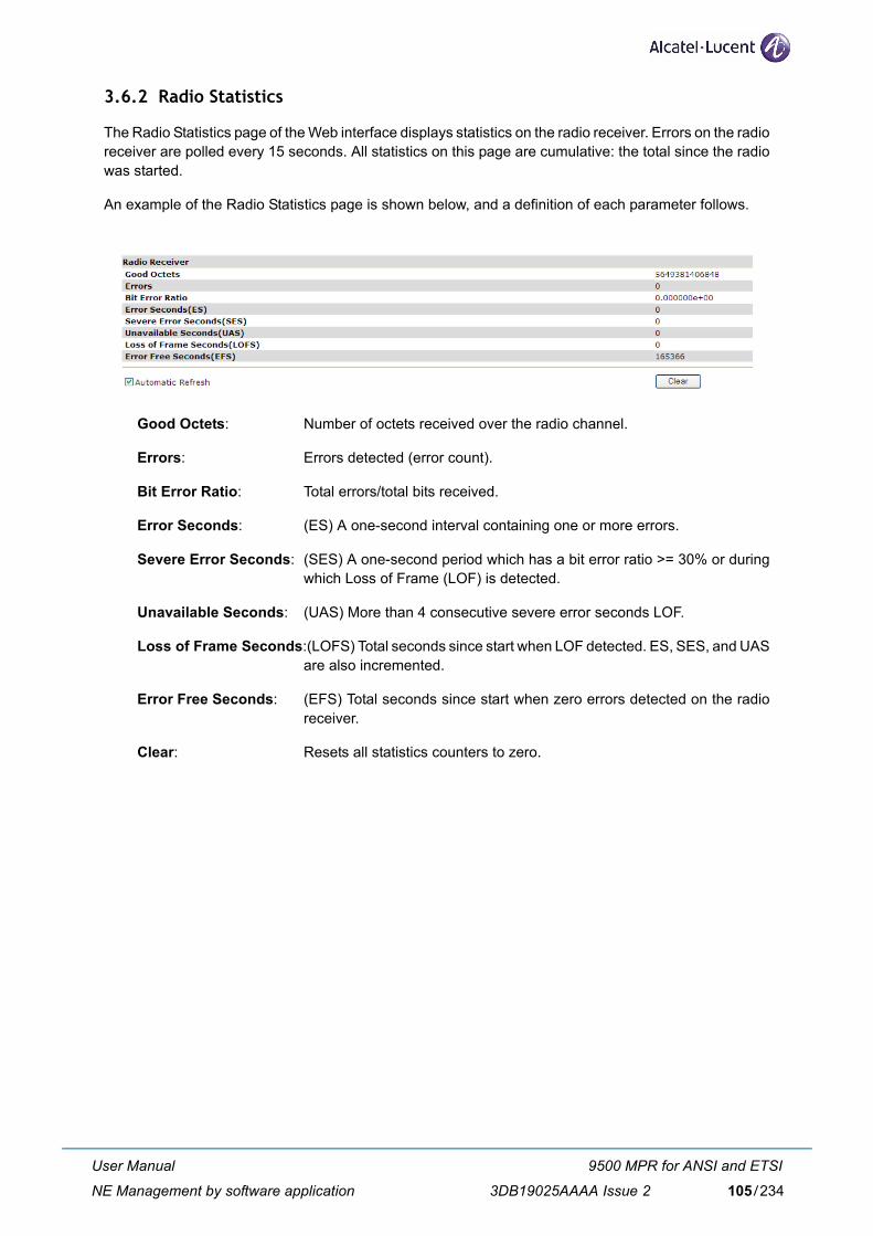
3.6.2 Radio Statistics
The Radio Statistics page of the Web interface displays statistics on the radio receiver. Errors on the radioreceiver are polled every 15 seconds. All statistics on this page are cumulative: the total since the radiowas started.
An example of the Radio Statistics page is shown below, and a definition of each parameter follows.
Good Octets: Number of octets received over the radio channel.
Errors: Errors detected (error count).
Bit Error Ratio: Total errors/total bits received.
Error Seconds: (ES) A one-second interval containing one or more errors.
Severe Error Seconds: (SES) A one-second period which has a bit error ratio >= 30% or duringwhich Loss of Frame (LOF) is detected.
Unavailable Seconds: (UAS) More than 4 consecutive severe error seconds LOF.
Loss of Frame Seconds:(LOFS) Total seconds since start when LOF detected. ES, SES, and UASare also incremented.
Error Free Seconds: (EFS) Total seconds since start when zero errors detected on the radioreceiver.
Clear: Resets all statistics counters to zero.
User Manual
NE Management by software application
9500 MPR for ANSI and ETSI
3DB19025AAAA Issue 2 105/234
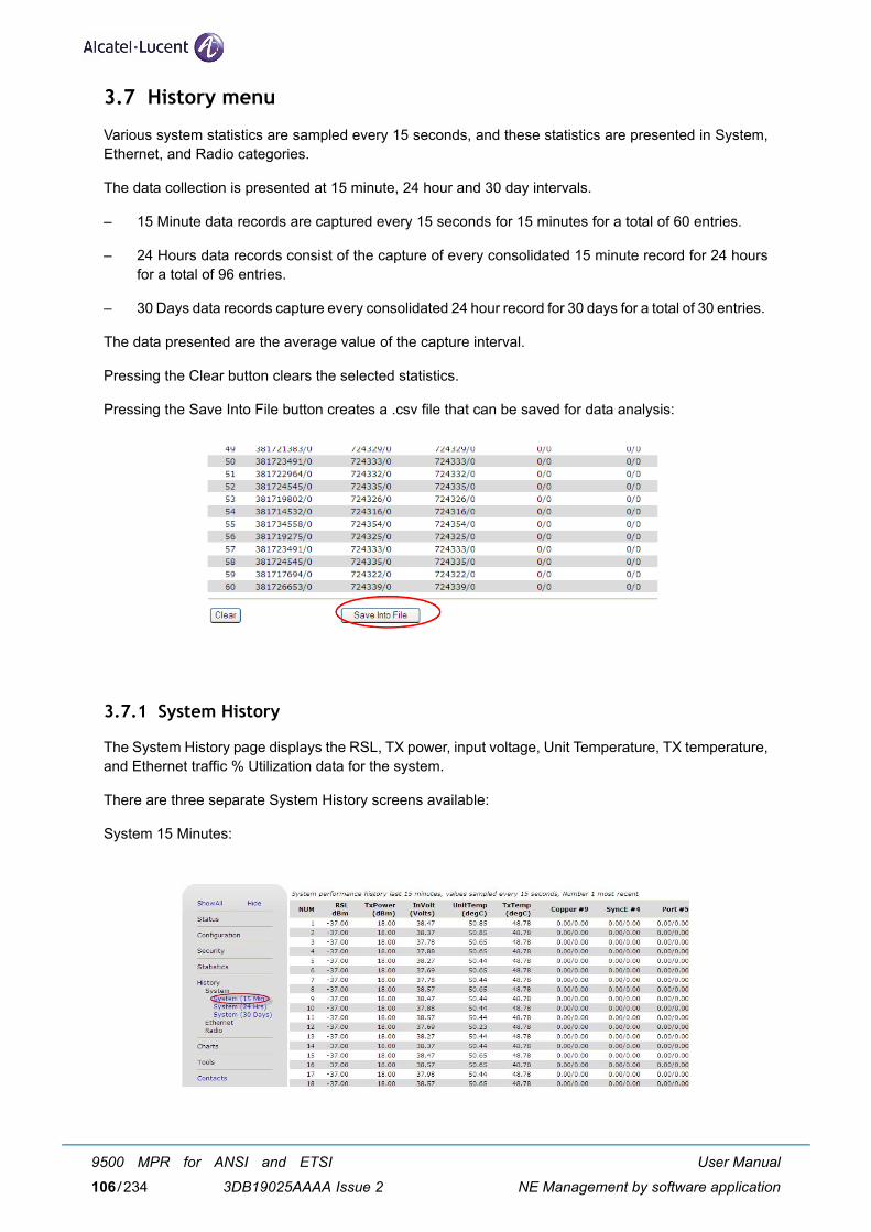
3.7 History menu
Various system statistics are sampled every 15 seconds, and these statistics are presented in System,Ethernet, and Radio categories.
The data collection is presented at 15 minute, 24 hour and 30 day intervals.
– 15 Minute data records are captured every 15 seconds for 15 minutes for a total of 60 entries.
– 24 Hours data records consist of the capture of every consolidated 15 minute record for 24 hoursfor a total of 96 entries.
– 30 Days data records capture every consolidated 24 hour record for 30 days for a total of 30 entries.
The data presented are the average value of the capture interval.
Pressing the Clear button clears the selected statistics.
Pressing the Save Into File button creates a .csv file that can be saved for data analysis:
3.7.1 System History
The System History page displays the RSL, TX power, input voltage, Unit Temperature, TX temperature,and Ethernet traffic % Utilization data for the system.
There are three separate System History screens available:
System 15 Minutes:
User Manual
NE Management by software application
9500 MPR for ANSI and ETSI
3DB19025AAAA Issue 2106/234
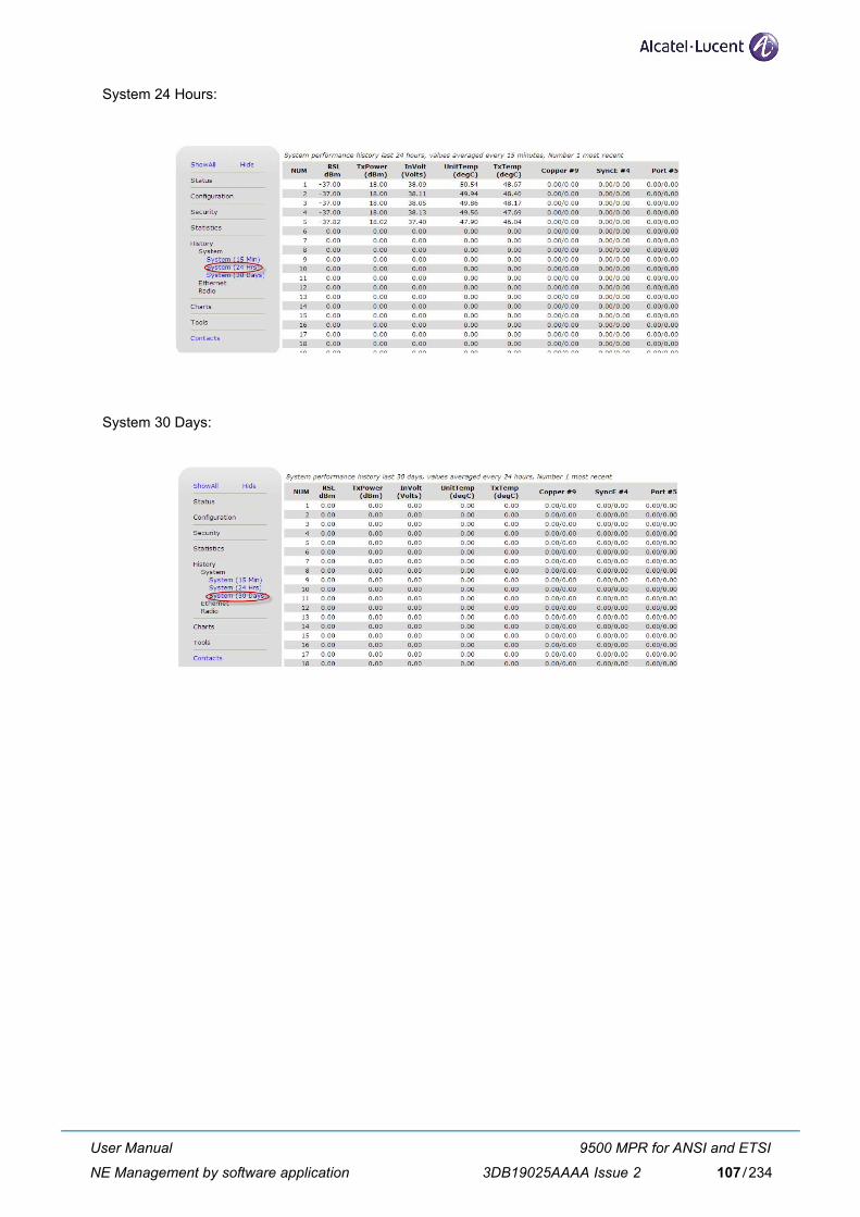
System 24 Hours:
System 30 Days:
User Manual
NE Management by software application
9500 MPR for ANSI and ETSI
3DB19025AAAA Issue 2 107/234
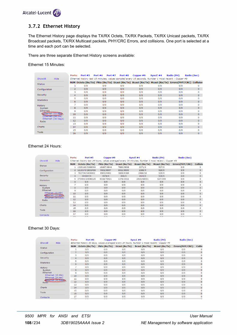
3.7.2 Ethernet History
The Ethernet History page displays the TX/RX Octets, TX/RX Packets, TX/RX Unicast packets, TX/RXBroadcast packets, TX/RX Multicast packets, PHY/CRC Errors, and collisions. One port is selected at atime and each port can be selected.
There are three separate Ethernet History screens available:
Ethernet 15 Minutes:
Ethernet 24 Hours:
Ethernet 30 Days:
User Manual
NE Management by software application
9500 MPR for ANSI and ETSI
3DB19025AAAA Issue 2108/234
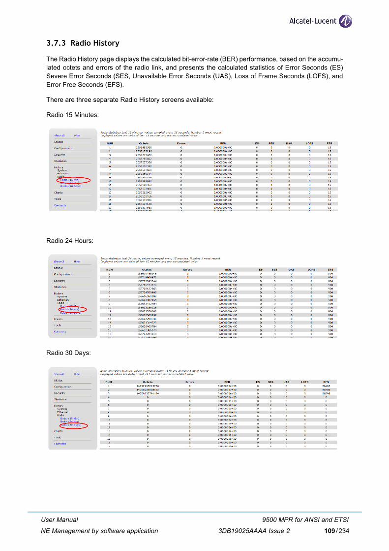
3.7.3 Radio History
The Radio History page displays the calculated bit-error-rate (BER) performance, based on the accumu-lated octets and errors of the radio link, and presents the calculated statistics of Error Seconds (ES)Severe Error Seconds (SES, Unavailable Error Seconds (UAS), Loss of Frame Seconds (LOFS), andError Free Seconds (EFS).
There are three separate Radio History screens available:
Radio 15 Minutes:
Radio 24 Hours:
Radio 30 Days:
User Manual
NE Management by software application
9500 MPR for ANSI and ETSI
3DB19025AAAA Issue 2 109/234
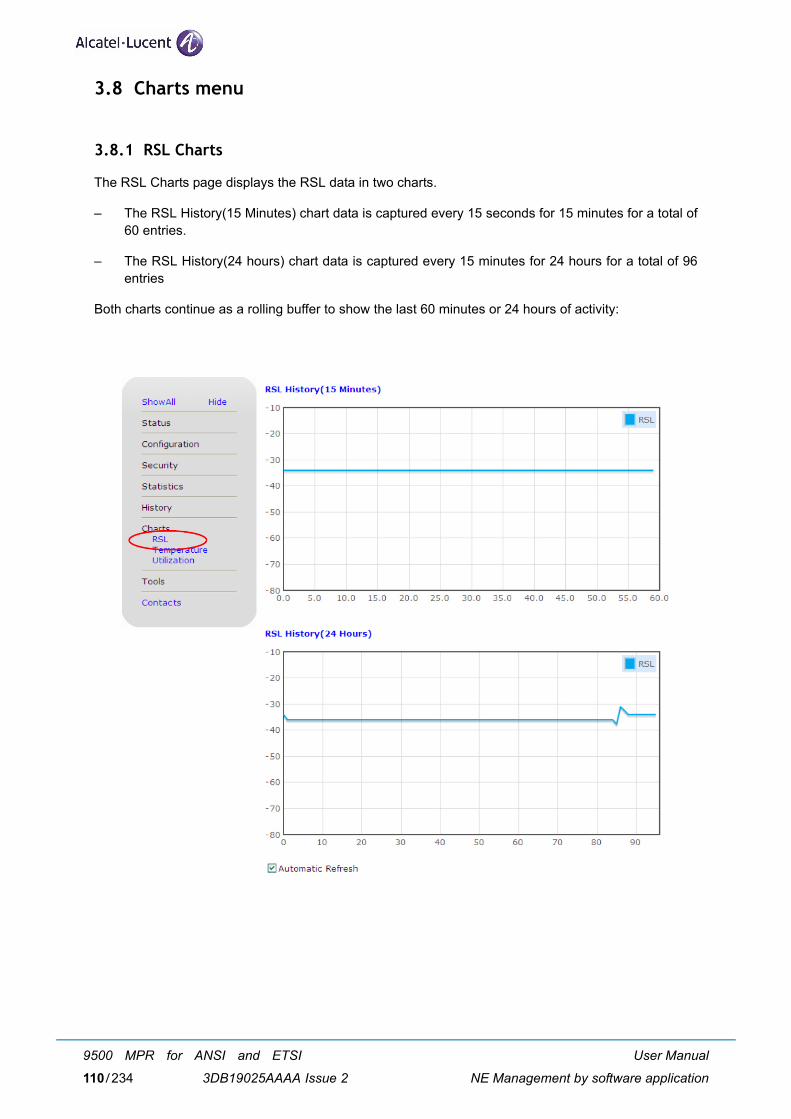
3.8 Charts menu
3.8.1 RSL Charts
The RSL Charts page displays the RSL data in two charts.
– The RSL History(15 Minutes) chart data is captured every 15 seconds for 15 minutes for a total of60 entries.
– The RSL History(24 hours) chart data is captured every 15 minutes for 24 hours for a total of 96entries
Both charts continue as a rolling buffer to show the last 60 minutes or 24 hours of activity:
User Manual
NE Management by software application
9500 MPR for ANSI and ETSI
3DB19025AAAA Issue 2110/234
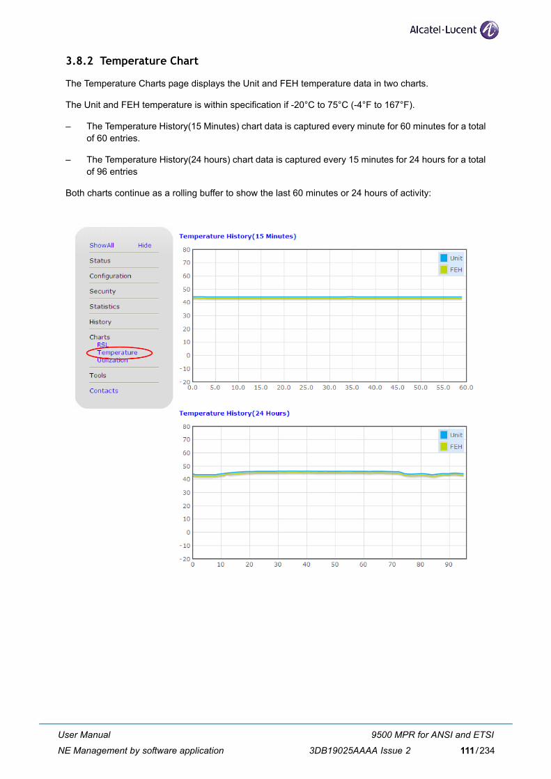
3.8.2 Temperature Chart
The Temperature Charts page displays the Unit and FEH temperature data in two charts.
The Unit and FEH temperature is within specification if -20°C to 75°C (-4°F to 167°F).
– The Temperature History(15 Minutes) chart data is captured every minute for 60 minutes for a totalof 60 entries.
– The Temperature History(24 hours) chart data is captured every 15 minutes for 24 hours for a totalof 96 entries
Both charts continue as a rolling buffer to show the last 60 minutes or 24 hours of activity:
User Manual
NE Management by software application
9500 MPR for ANSI and ETSI
3DB19025AAAA Issue 2 111/234
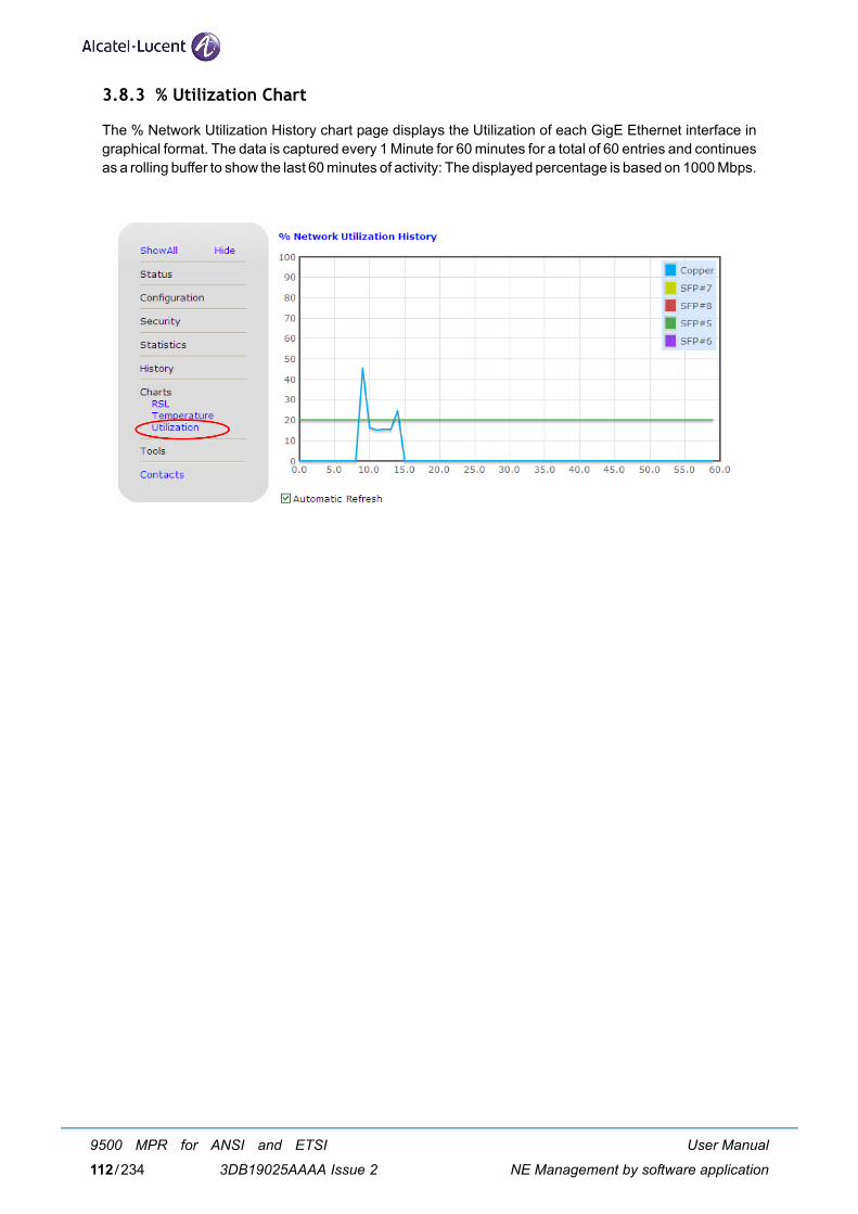
3.8.3 % Utilization Chart
The % Network Utilization History chart page displays the Utilization of each GigE Ethernet interface ingraphical format. The data is captured every 1 Minute for 60 minutes for a total of 60 entries and continuesas a rolling buffer to show the last 60 minutes of activity: The displayed percentage is based on 1000 Mbps.
User Manual
NE Management by software application
9500 MPR for ANSI and ETSI
3DB19025AAAA Issue 2112/234
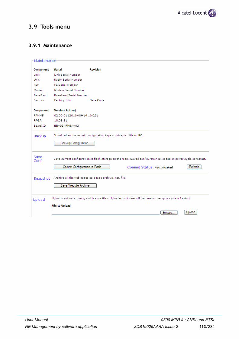
3.9 Tools menu
3.9.1 Maintenance
User Manual
NE Management by software application
9500 MPR for ANSI and ETSI
3DB19025AAAA Issue 2 113/234
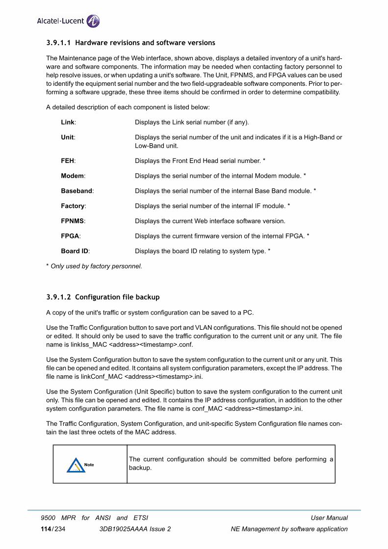
3.9.1.1 Hardware revisions and software versions
The Maintenance page of the Web interface, shown above, displays a detailed inventory of a unit's hard-ware and software components. The information may be needed when contacting factory personnel tohelp resolve issues, or when updating a unit's software. The Unit, FPNMS, and FPGA values can be usedto identify the equipment serial number and the two field-upgradeable software components. Prior to per-forming a software upgrade, these three items should be confirmed in order to determine compatibility.
A detailed description of each component is listed below:
Link: Displays the Link serial number (if any).
Unit: Displays the serial number of the unit and indicates if it is a High-Band orLow-Band unit.
FEH: Displays the Front End Head serial number. *
Modem: Displays the serial number of the internal Modem module. *
Baseband: Displays the serial number of the internal Base Band module. *
Factory: Displays the serial number of the internal IF module. *
FPNMS: Displays the current Web interface software version.
FPGA: Displays the current firmware version of the internal FPGA. *
Board ID: Displays the board ID relating to system type. *
* Only used by factory personnel.
3.9.1.2 Configuration file backup
A copy of the unit's traffic or system configuration can be saved to a PC.
Use the Traffic Configuration button to save port and VLAN configurations. This file should not be openedor edited. It should only be used to save the traffic configuration to the current unit or any unit. The filename is linkIss_MAC <address><timestamp>.conf.
Use the System Configuration button to save the system configuration to the current unit or any unit. Thisfile can be opened and edited. It contains all system configuration parameters, except the IP address. Thefile name is linkConf_MAC <address><timestamp>.ini.
Use the System Configuration (Unit Specific) button to save the system configuration to the current unitonly. This file can be opened and edited. It contains the IP address configuration, in addition to the othersystem configuration parameters. The file name is conf_MAC <address><timestamp>.ini.
The Traffic Configuration, System Configuration, and unit-specific System Configuration file names con-tain the last three octets of the MAC address.
The current configuration should be committed before performing abackup.
User Manual
NE Management by software application
9500 MPR for ANSI and ETSI
3DB19025AAAA Issue 2114/234
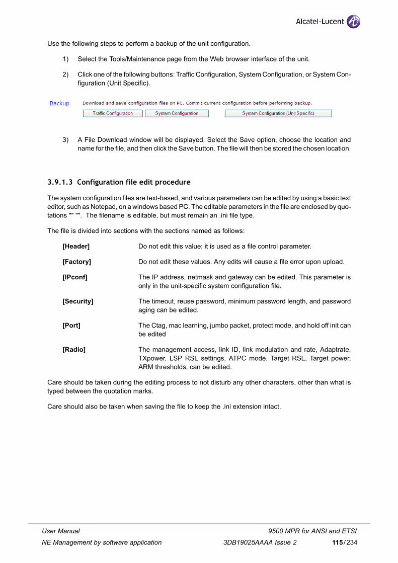
Use the following steps to perform a backup of the unit configuration.
1) Select the Tools/Maintenance page from the Web browser interface of the unit.
2) Click one of the following buttons: Traffic Configuration, System Configuration, or System Con-figuration (Unit Specific).
3) A File Download window will be displayed. Select the Save option, choose the location andname for the file, and then click the Save button. The file will then be stored the chosen location.
3.9.1.3 Configuration file edit procedure
The system configuration files are text-based, and various parameters can be edited by using a basic texteditor, such as Notepad, on a windows based PC. The editable parameters in the file are enclosed by quo-tations "" "". The filename is editable, but must remain an .ini file type.
The file is divided into sections with the sections named as follows:
[Header] Do not edit this value; it is used as a file control parameter.
[Factory] Do not edit these values. Any edits will cause a file error upon upload.
[IPconf] The IP address, netmask and gateway can be edited. This parameter isonly in the unit-specific system configuration file.
[Security] The timeout, reuse password, minimum password length, and passwordaging can be edited.
[Port] The Ctag, mac learning, jumbo packet, protect mode, and hold off init canbe edited
[Radio] The management access, link ID, link modulation and rate, Adaptrate,TXpower, LSP RSL settings, ATPC mode, Target RSL, Target power,ARM thresholds, can be edited.
Care should be taken during the editing process to not disturb any other characters, other than what istyped between the quotation marks.
Care should also be taken when saving the file to keep the .ini extension intact.
User Manual
NE Management by software application
9500 MPR for ANSI and ETSI
3DB19025AAAA Issue 2 115/234
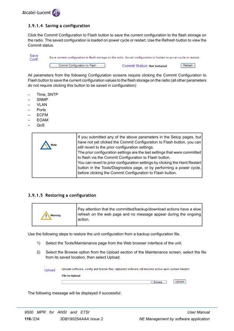
3.9.1.4 Saving a configuration
Click the Commit Configuration to Flash button to save the current configuration to the flash storage onthe radio. The saved configuration is loaded on power cycle or restart. Use the Refresh button to view theCommit status.
All parameters from the following Configuration screens require clicking the Commit Configuration toFlash button to save the current configuration values to the flash storage on the radio (all other parametersdo not require clicking this button to be saved in configuration):
– Time, SNTP– SNMP– VLAN– Ports– ECFM– EOAM– QoS
3.9.1.5 Restoring a configuration
Use the following steps to restore the unit configuration from a backup configuration file.
1) Select the Tools/Maintenance page from the Web browser interface of the unit.
2) Select the Browse option from the Upload section of the Maintenance screen, select the filefrom its saved location, then select Upload.
The following message will be displayed if successful:
If you submitted any of the above parameters in the Setup pages, buthave not yet clicked the Commit Configuration to Flash button, you canstill revert to the prior configuration settings.The prior configuration settings are the last settings that were committedto flash via the Commit Configuration to Flash button.You can revert to prior configuration settings by clicking the Hard Restartbutton in the Tools/Diagnostics page, or by performing a power cycle,before clicking the Commit Configuration to Flash button.
Pay attention that the committed/backup/download actions have a slowrefresh on the web page and no message appear during the ongoingaction.
User Manual
NE Management by software application
9500 MPR for ANSI and ETSI
3DB19025AAAA Issue 2116/234
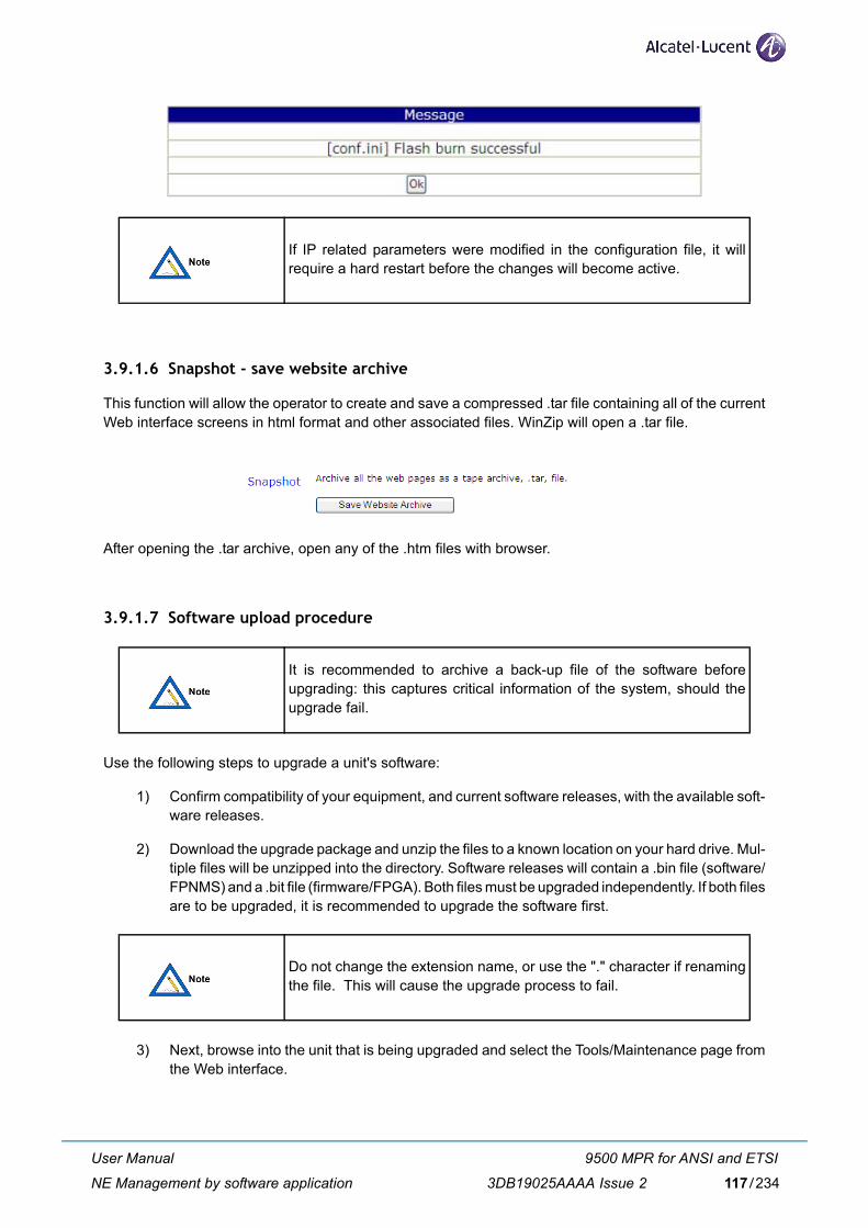
3.9.1.6 Snapshot - save website archive
This function will allow the operator to create and save a compressed .tar file containing all of the currentWeb interface screens in html format and other associated files. WinZip will open a .tar file.
After opening the .tar archive, open any of the .htm files with browser.
3.9.1.7 Software upload procedure
Use the following steps to upgrade a unit's software:
1) Confirm compatibility of your equipment, and current software releases, with the available soft-ware releases.
2) Download the upgrade package and unzip the files to a known location on your hard drive. Mul-tiple files will be unzipped into the directory. Software releases will contain a .bin file (software/FPNMS) and a .bit file (firmware/FPGA). Both files must be upgraded independently. If both filesare to be upgraded, it is recommended to upgrade the software first.
3) Next, browse into the unit that is being upgraded and select the Tools/Maintenance page fromthe Web interface.
If IP related parameters were modified in the configuration file, it willrequire a hard restart before the changes will become active.
It is recommended to archive a back-up file of the software beforeupgrading: this captures critical information of the system, should theupgrade fail.
Do not change the extension name, or use the "." character if renamingthe file. This will cause the upgrade process to fail.
User Manual
NE Management by software application
9500 MPR for ANSI and ETSI
3DB19025AAAA Issue 2 117/234
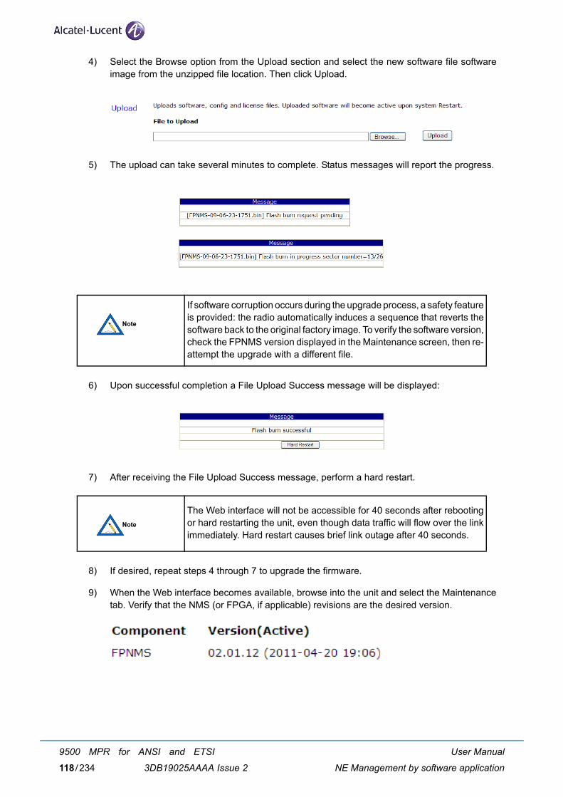
4) Select the Browse option from the Upload section and select the new software file softwareimage from the unzipped file location. Then click Upload.
5) The upload can take several minutes to complete. Status messages will report the progress.
6) Upon successful completion a File Upload Success message will be displayed:
7) After receiving the File Upload Success message, perform a hard restart.
8) If desired, repeat steps 4 through 7 to upgrade the firmware.
9) When the Web interface becomes available, browse into the unit and select the Maintenancetab. Verify that the NMS (or FPGA, if applicable) revisions are the desired version.
If software corruption occurs during the upgrade process, a safety featureis provided: the radio automatically induces a sequence that reverts thesoftware back to the original factory image. To verify the software version,check the FPNMS version displayed in the Maintenance screen, then re-attempt the upgrade with a different file.
The Web interface will not be accessible for 40 seconds after rebootingor hard restarting the unit, even though data traffic will flow over the linkimmediately. Hard restart causes brief link outage after 40 seconds.
User Manual
NE Management by software application
9500 MPR for ANSI and ETSI
3DB19025AAAA Issue 2118/234
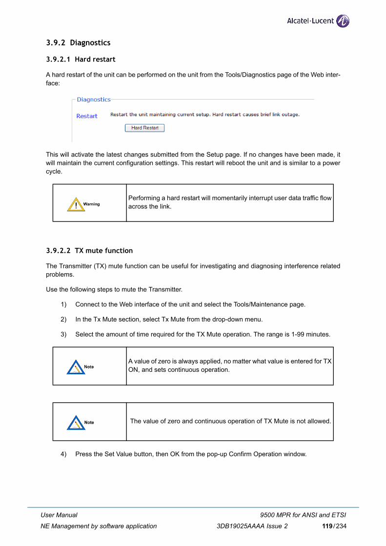
3.9.2 Diagnostics
3.9.2.1 Hard restart
A hard restart of the unit can be performed on the unit from the Tools/Diagnostics page of the Web inter-face:
This will activate the latest changes submitted from the Setup page. If no changes have been made, itwill maintain the current configuration settings. This restart will reboot the unit and is similar to a powercycle.
3.9.2.2 TX mute function
The Transmitter (TX) mute function can be useful for investigating and diagnosing interference relatedproblems.
Use the following steps to mute the Transmitter.
1) Connect to the Web interface of the unit and select the Tools/Maintenance page.
2) In the Tx Mute section, select Tx Mute from the drop-down menu.
3) Select the amount of time required for the TX Mute operation. The range is 1-99 minutes.
4) Press the Set Value button, then OK from the pop-up Confirm Operation window.
Performing a hard restart will momentarily interrupt user data traffic flowacross the link.
A value of zero is always applied, no matter what value is entered for TXON, and sets continuous operation.
The value of zero and continuous operation of TX Mute is not allowed.
User Manual
NE Management by software application
9500 MPR for ANSI and ETSI
3DB19025AAAA Issue 2 119/234
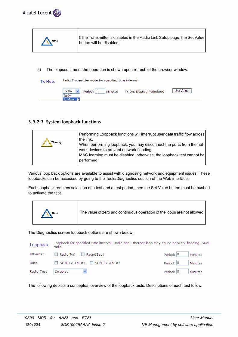
5) The elapsed time of the operation is shown upon refresh of the browser window.
3.9.2.3 System loopback functions
Various loop back options are available to assist with diagnosing network and equipment issues. Theseloopbacks can be accessed by going to the Tools/Diagnostics section of the Web interface.
Each loopback requires selection of a test and a test period, then the Set Value button must be pushedto activate the test.
The Diagnostics screen loopback options are shown below:
The following depicts a conceptual overview of the loopback tests. Descriptions of each test follow.
If the Transmitter is disabled in the Radio Link Setup page, the Set Valuebutton will be disabled.
Performing Loopback functions will interrupt user data traffic flow acrossthe link.When performing loopback, you may disconnect the ports from the net-work devices to prevent network flooding.MAC learning must be disabled, otherwise, the loopback test cannot beperformed.
The value of zero and continuous operation of the loops are not allowed.
User Manual
NE Management by software application
9500 MPR for ANSI and ETSI
3DB19025AAAA Issue 2120/234
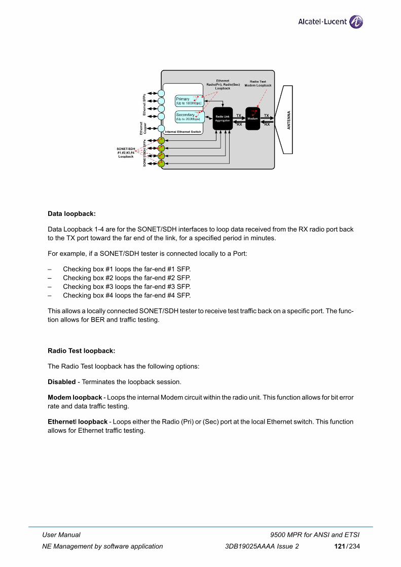
Data loopback:
Data Loopback 1-4 are for the SONET/SDH interfaces to loop data received from the RX radio port backto the TX port toward the far end of the link, for a specified period in minutes.
For example, if a SONET/SDH tester is connected locally to a Port:
– Checking box #1 loops the far-end #1 SFP.– Checking box #2 loops the far-end #2 SFP.– Checking box #3 loops the far-end #3 SFP.– Checking box #4 loops the far-end #4 SFP.
This allows a locally connected SONET/SDH tester to receive test traffic back on a specific port. The func-tion allows for BER and traffic testing.
Radio Test loopback:
The Radio Test loopback has the following options:
Disabled - Terminates the loopback session.
Modem loopback - Loops the internal Modem circuit within the radio unit. This function allows for bit errorrate and data traffic testing.
Ethernetl loopback - Loops either the Radio (Pri) or (Sec) port at the local Ethernet switch. This functionallows for Ethernet traffic testing.
User Manual
NE Management by software application
9500 MPR for ANSI and ETSI
3DB19025AAAA Issue 2 121/234
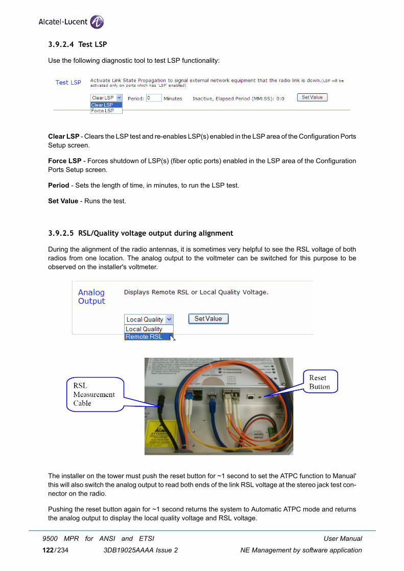
3.9.2.4 Test LSP
Use the following diagnostic tool to test LSP functionality:
Clear LSP - Clears the LSP test and re-enables LSP(s) enabled in the LSP area of the Configuration PortsSetup screen.
Force LSP - Forces shutdown of LSP(s) (fiber optic ports) enabled in the LSP area of the ConfigurationPorts Setup screen.
Period - Sets the length of time, in minutes, to run the LSP test.
Set Value - Runs the test.
3.9.2.5 RSL/Quality voltage output during alignment
During the alignment of the radio antennas, it is sometimes very helpful to see the RSL voltage of bothradios from one location. The analog output to the voltmeter can be switched for this purpose to beobserved on the installer's voltmeter.
The installer on the tower must push the reset button for ~1 second to set the ATPC function to Manual'this will also switch the analog output to read both ends of the link RSL voltage at the stereo jack test con-nector on the radio.
Pushing the reset button again for ~1 second returns the system to Automatic ATPC mode and returnsthe analog output to display the local quality voltage and RSL voltage.
User Manual
NE Management by software application
9500 MPR for ANSI and ETSI
3DB19025AAAA Issue 2122/234
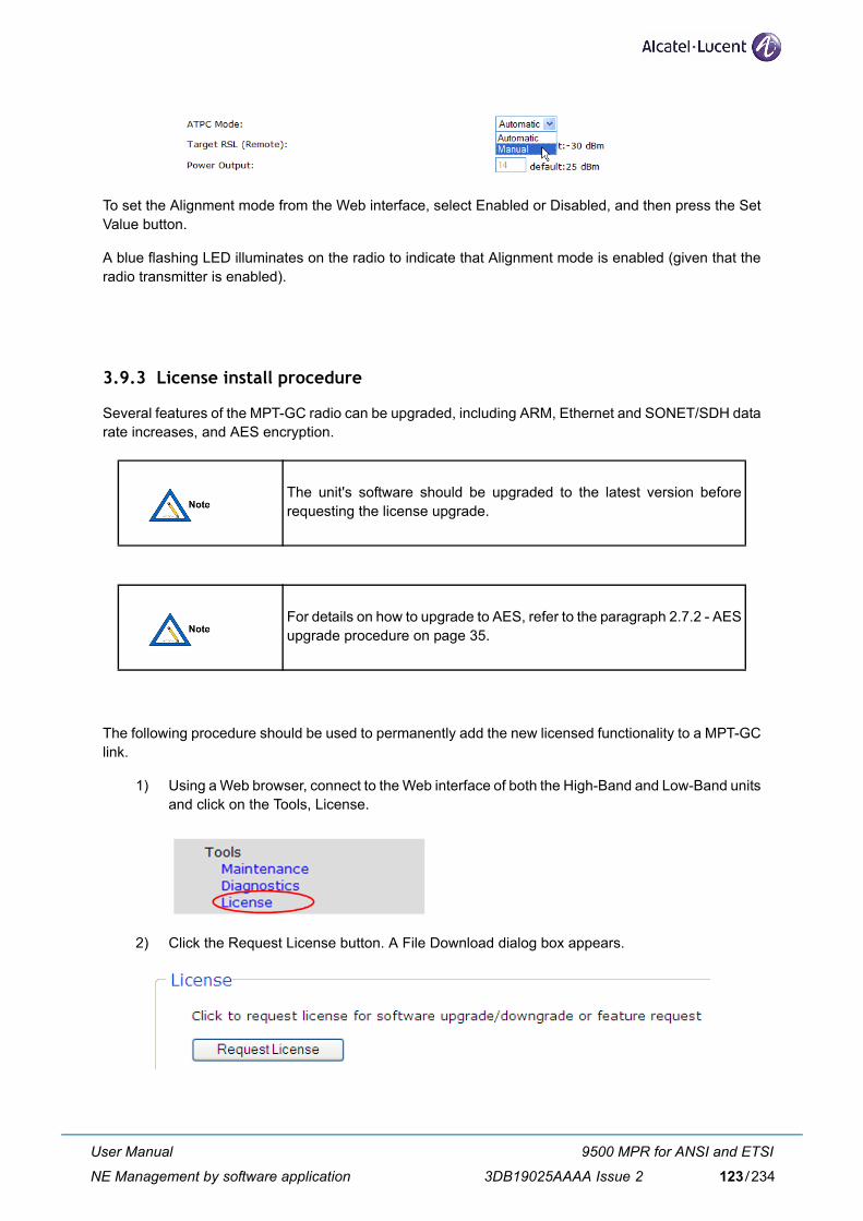
To set the Alignment mode from the Web interface, select Enabled or Disabled, and then press the SetValue button.
A blue flashing LED illuminates on the radio to indicate that Alignment mode is enabled (given that theradio transmitter is enabled).
3.9.3 License install procedure
Several features of the MPT-GC radio can be upgraded, including ARM, Ethernet and SONET/SDH datarate increases, and AES encryption.
The following procedure should be used to permanently add the new licensed functionality to a MPT-GClink.
1) Using a Web browser, connect to the Web interface of both the High-Band and Low-Band unitsand click on the Tools, License.
2) Click the Request License button. A File Download dialog box appears.
The unit's software should be upgraded to the latest version beforerequesting the license upgrade.
For details on how to upgrade to AES, refer to the paragraph 2.7.2 - AESupgrade procedure on page 35.
User Manual
NE Management by software application
9500 MPR for ANSI and ETSI
3DB19025AAAA Issue 2 123/234
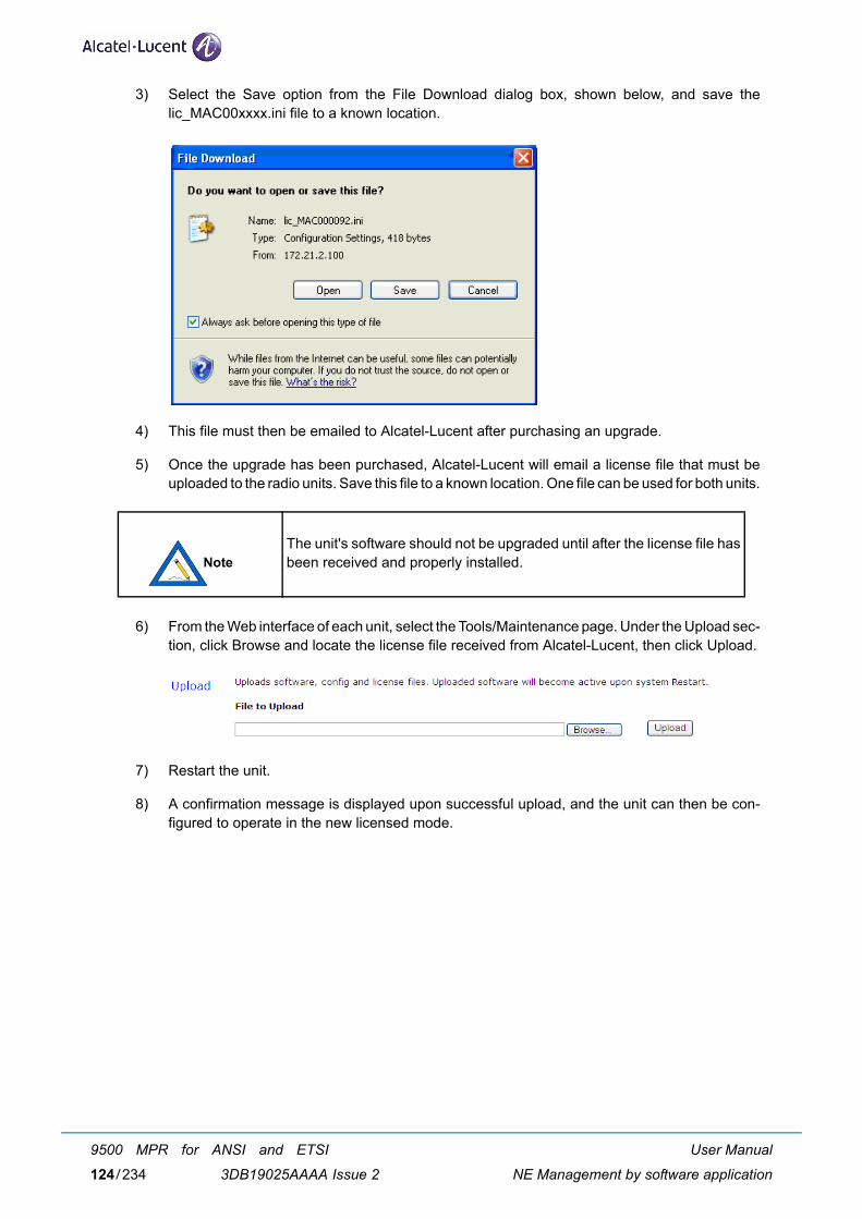
3) Select the Save option from the File Download dialog box, shown below, and save thelic_MAC00xxxx.ini file to a known location.
4) This file must then be emailed to Alcatel-Lucent after purchasing an upgrade.
5) Once the upgrade has been purchased, Alcatel-Lucent will email a license file that must beuploaded to the radio units. Save this file to a known location. One file can be used for both units.
6) From the Web interface of each unit, select the Tools/Maintenance page. Under the Upload sec-tion, click Browse and locate the license file received from Alcatel-Lucent, then click Upload.
7) Restart the unit.
8) A confirmation message is displayed upon successful upload, and the unit can then be con-figured to operate in the new licensed mode.
The unit's software should not be upgraded until after the license file hasbeen received and properly installed.
User Manual
NE Management by software application
9500 MPR for ANSI and ETSI
3DB19025AAAA Issue 2124/234
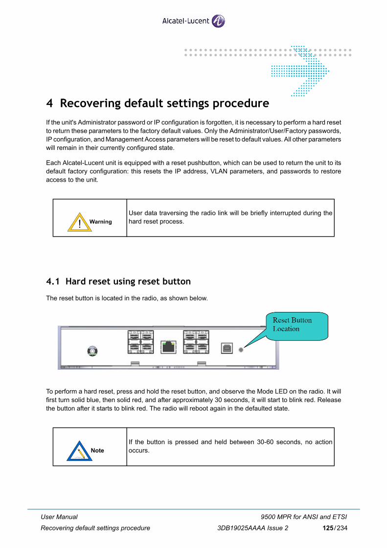
4 Recovering default settings procedureIf the unit's Administrator password or IP configuration is forgotten, it is necessary to perform a hard resetto return these parameters to the factory default values. Only the Administrator/User/Factory passwords,IP configuration, and Management Access parameters will be reset to default values. All other parameterswill remain in their currently configured state.
Each Alcatel-Lucent unit is equipped with a reset pushbutton, which can be used to return the unit to itsdefault factory configuration: this resets the IP address, VLAN parameters, and passwords to restoreaccess to the unit.
4.1 Hard reset using reset button
The reset button is located in the radio, as shown below.
To perform a hard reset, press and hold the reset button, and observe the Mode LED on the radio. It willfirst turn solid blue, then solid red, and after approximately 30 seconds, it will start to blink red. Releasethe button after it starts to blink red. The radio will reboot again in the defaulted state.
User data traversing the radio link will be briefly interrupted during thehard reset process.
If the button is pressed and held between 30-60 seconds, no actionoccurs.
User Manual
Recovering default settings procedure
9500 MPR for ANSI and ETSI
3DB19025AAAA Issue 2 125/234

4.2 Hard reset using hard reset cable
Alternatively, you can perform a hard reset by creating your own hard reset cable.
It is required to have physical access to the unit's Copper Port #9 (RJ-45 jack) and the unit's power cable.
Use the following procedure to perform a hard reset with a hard reset cable:
1) Obtain a standard Ethernet patch cable, at least 3 meters in length.
2) Cut off one end of the Ethernet patch cable, and then strip the jacket from the 2 wires that belongto pins 3 and 6. These are typically the wires from either the orange/white-orange or green/white-green pairs, but this is not guaranteed to be the case.
3) Connect the 2 wires from pins 3 and 6 together to make a short. All other wires must be left un-terminated.
4) Power down the unit.
5) Connect the hard reset cable to the Copper Port #9 (RJ45) on the unit.
6) Reconnect power to the unit and wait a minimum of 3 minutes.
The unit will then begin its normal restart cycle, and the Web interface will normally become accessiblewithin approximately 3-4 minutes using the default IP configuration, user names, passwords and com-munity strings.
4.3 Forcing radio to original factory image
If the software is corrupt, the radio can be returned to the factory-default Web interface image from theback-up memory bank. To boot up the Web interface from the back-up memory bank, follow the procedurebelow.
1) Power down the radio.
2) Power up the radio.
3) Wait until the green TX Status/Activity LED blinks (~40 seconds).
4) Press and hold the reset button for 5 seconds, then release
This will recover the original factory default image, which serves as the backup image.
User Manual
Recovering default settings procedure
9500 MPR for ANSI and ETSI
3DB19025AAAA Issue 2126/234
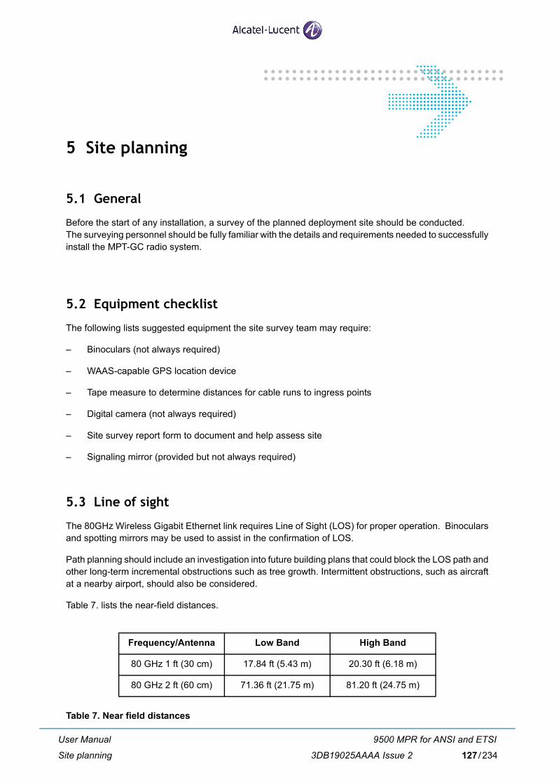
5 Site planning
5.1 General
Before the start of any installation, a survey of the planned deployment site should be conducted. The surveying personnel should be fully familiar with the details and requirements needed to successfullyinstall the MPT-GC radio system.
5.2 Equipment checklist
The following lists suggested equipment the site survey team may require:
– Binoculars (not always required)
– WAAS-capable GPS location device
– Tape measure to determine distances for cable runs to ingress points
– Digital camera (not always required)
– Site survey report form to document and help assess site
– Signaling mirror (provided but not always required)
5.3 Line of sight
The 80GHz Wireless Gigabit Ethernet link requires Line of Sight (LOS) for proper operation. Binocularsand spotting mirrors may be used to assist in the confirmation of LOS.
Path planning should include an investigation into future building plans that could block the LOS path andother long-term incremental obstructions such as tree growth. Intermittent obstructions, such as aircraftat a nearby airport, should also be considered.
Table 7. lists the near-field distances.
Table 7. Near field distances
Frequency/Antenna Low Band High Band
80 GHz 1 ft (30 cm) 17.84 ft (5.43 m) 20.30 ft (6.18 m)
80 GHz 2 ft (60 cm) 71.36 ft (21.75 m) 81.20 ft (24.75 m)
User Manual
Site planning
9500 MPR for ANSI and ETSI
3DB19025AAAA Issue 2 127/234
Table 8. details the minimum F1 (First Fresnel) clearance needed from obstacles in order to ensure theradios will operate properly.
Table 8. Minimum path clearance
5.4 Link distance
Measurement of the link distance is important in estimating the link availability and calculating expectedReceive Signal Level (RSL). This measurement can be performed using the Latitude and Longitude coor-dinate readings from a Global Positioning System (GPS) device, which is placed near the proposed loca-tions of the antennas. Additionally GPS reading will be required in order to comply with the FCCregistration process.
The Minimum 80GHz Link distances are as follows:
– MPT-GC 12” (30 cm antenna): 100 meters (328 feet)
– MPT-GC 24” (60 cm antenna): 400 meters (1312 feet)
Contact Alcatel-Lucent to estimate maximum distances and availabilities for a given product and region.
5.5 Antenna location
The optimum location for the antennas must be determined. The ideal location should provide for easeof erecting and mounting the antenna, as well as providing unimpeded LOS to the remote location. Thefollowing factors should be taken into account:
– Type of mounting-fixed or roof-safe pole mounting.
– Location of fiber and DC power wiring ingress/egress of the building.
– Length of cable runs.
– Confirmed Earth Grounding connection points.
– Obstructions, including allowances for tree growth.
– Accessibility of the radio mounting location.
– Accessibility of the site during and after working hours.
Path length (meters)
Minimum F1 clearance (meters)
Path length (miles)
Minimum F1 clearance (feet)
1000 0.58 0.62 1.9
2000 0.82 1.24 2.7
5000 1.3 3.10 4.3
10000 1.8 6.21 5.9
User Manual
Site planning
9500 MPR for ANSI and ETSI
3DB19025AAAA Issue 2128/234
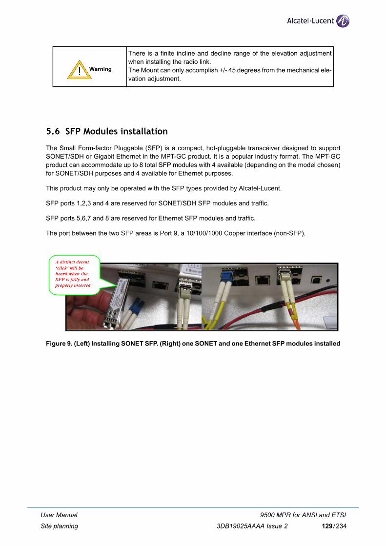
5.6 SFP Modules installation
The Small Form-factor Pluggable (SFP) is a compact, hot-pluggable transceiver designed to supportSONET/SDH or Gigabit Ethernet in the MPT-GC product. It is a popular industry format. The MPT-GCproduct can accommodate up to 8 total SFP modules with 4 available (depending on the model chosen)for SONET/SDH purposes and 4 available for Ethernet purposes.
This product may only be operated with the SFP types provided by Alcatel-Lucent.
SFP ports 1,2,3 and 4 are reserved for SONET/SDH SFP modules and traffic.
SFP ports 5,6,7 and 8 are reserved for Ethernet SFP modules and traffic.
The port between the two SFP areas is Port 9, a 10/100/1000 Copper interface (non-SFP).
Figure 9. (Left) Installing SONET SFP. (Right) one SONET and one Ethernet SFP modules installed
There is a finite incline and decline range of the elevation adjustmentwhen installing the radio link. The Mount can only accomplish +/- 45 degrees from the mechanical ele-vation adjustment.
User Manual
Site planning
9500 MPR for ANSI and ETSI
3DB19025AAAA Issue 2 129/234
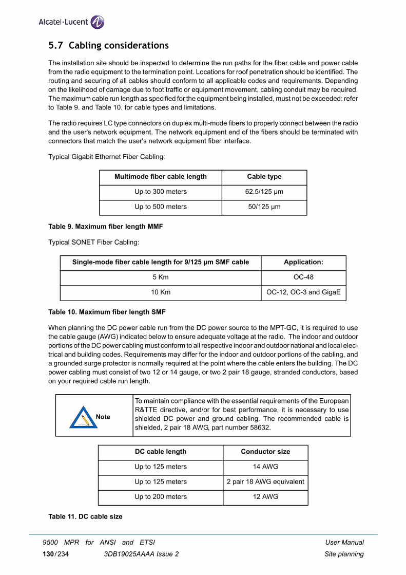
5.7 Cabling considerations
The installation site should be inspected to determine the run paths for the fiber cable and power cablefrom the radio equipment to the termination point. Locations for roof penetration should be identified. Therouting and securing of all cables should conform to all applicable codes and requirements. Dependingon the likelihood of damage due to foot traffic or equipment movement, cabling conduit may be required.The maximum cable run length as specified for the equipment being installed, must not be exceeded: referto Table 9. and Table 10. for cable types and limitations.
The radio requires LC type connectors on duplex multi-mode fibers to properly connect between the radioand the user's network equipment. The network equipment end of the fibers should be terminated withconnectors that match the user's network equipment fiber interface.
Typical Gigabit Ethernet Fiber Cabling:
Table 9. Maximum fiber length MMF
Typical SONET Fiber Cabling:
Table 10. Maximum fiber length SMF
When planning the DC power cable run from the DC power source to the MPT-GC, it is required to usethe cable gauge (AWG) indicated below to ensure adequate voltage at the radio. The indoor and outdoorportions of the DC power cabling must conform to all respective indoor and outdoor national and local elec-trical and building codes. Requirements may differ for the indoor and outdoor portions of the cabling, anda grounded surge protector is normally required at the point where the cable enters the building. The DCpower cabling must consist of two 12 or 14 gauge, or two 2 pair 18 gauge, stranded conductors, basedon your required cable run length.
Table 11. DC cable size
Multimode fiber cable length Cable type
Up to 300 meters 62.5/125 µm
Up to 500 meters 50/125 µm
Single-mode fiber cable length for 9/125 µm SMF cable Application:
5 Km OC-48
10 Km OC-12, OC-3 and GigaE
To maintain compliance with the essential requirements of the EuropeanR&TTE directive, and/or for best performance, it is necessary to useshielded DC power and ground cabling. The recommended cable isshielded, 2 pair 18 AWG, part number 58632.
DC cable length Conductor size
Up to 125 meters 14 AWG
Up to 125 meters 2 pair 18 AWG equivalent
Up to 200 meters 12 AWG
User Manual
Site planning
9500 MPR for ANSI and ETSI
3DB19025AAAA Issue 2130/234
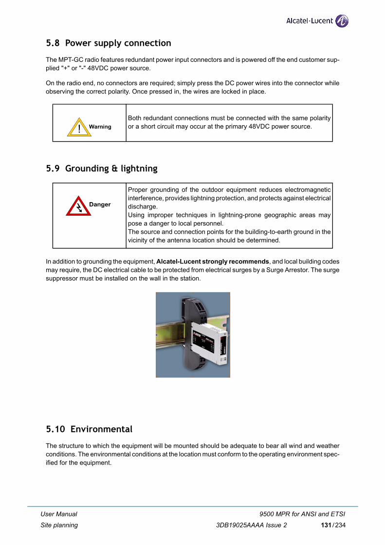
5.8 Power supply connection
The MPT-GC radio features redundant power input connectors and is powered off the end customer sup-plied "+" or "-" 48VDC power source.
On the radio end, no connectors are required; simply press the DC power wires into the connector whileobserving the correct polarity. Once pressed in, the wires are locked in place.
5.9 Grounding & lightning
In addition to grounding the equipment, Alcatel-Lucent strongly recommends, and local building codesmay require, the DC electrical cable to be protected from electrical surges by a Surge Arrestor. The surgesuppressor must be installed on the wall in the station.
5.10 Environmental
The structure to which the equipment will be mounted should be adequate to bear all wind and weatherconditions. The environmental conditions at the location must conform to the operating environment spec-ified for the equipment.
Both redundant connections must be connected with the same polarityor a short circuit may occur at the primary 48VDC power source.
Proper grounding of the outdoor equipment reduces electromagneticinterference, provides lightning protection, and protects against electricaldischarge. Using improper techniques in lightning-prone geographic areas maypose a danger to local personnel.The source and connection points for the building-to-earth ground in thevicinity of the antenna location should be determined.
User Manual
Site planning
9500 MPR for ANSI and ETSI
3DB19025AAAA Issue 2 131/234

User Manual
Site planning
9500 MPR for ANSI and ETSI
3DB19025AAAA Issue 2132/234
6 Installation
6.1 General
It is recommended that installation personnel read this section in its entirety prior to installing the Alcatel-Lucent System. During a particular phase of installation, the user may refer directly to the applicable sub-section.
The Installation section is comprised of the following subsections covering the procedures and guidelinesfor installing the Alcatel-Lucent Radio System.
Warning: to make sure of the continuity and avoid short circuit, all cables / connectors connections (RJ45,Coaxial, Ethernet, Optical Fiber) make on the field has to be verified and checked with Cable tester andmake sure of the waterproofness.
6.2 Equipment unpacking
The radio system equipment will arrive in four boxes-two boxes for the two antenna and mounting kits andtwo boxes containing the radio unit (one low-band and one high-band). Locate the correct box (low bandor high band) before beginning installation by checking the label on the outside of the box or on the radioitself. It is recommended that the shipping cartons and packing materials be retained in the event that itis necessary to return any equipment.
The radiated polarity can be identified on unpacked radios by the first letterof the polarity V or H (Vertical or Horizontal) on the top of the unit handle orby the polarization labels. See Figure 27. for further details.
User Manual
Installation
9500 MPR for ANSI and ETSI
3DB19025AAAA Issue 2 133/234
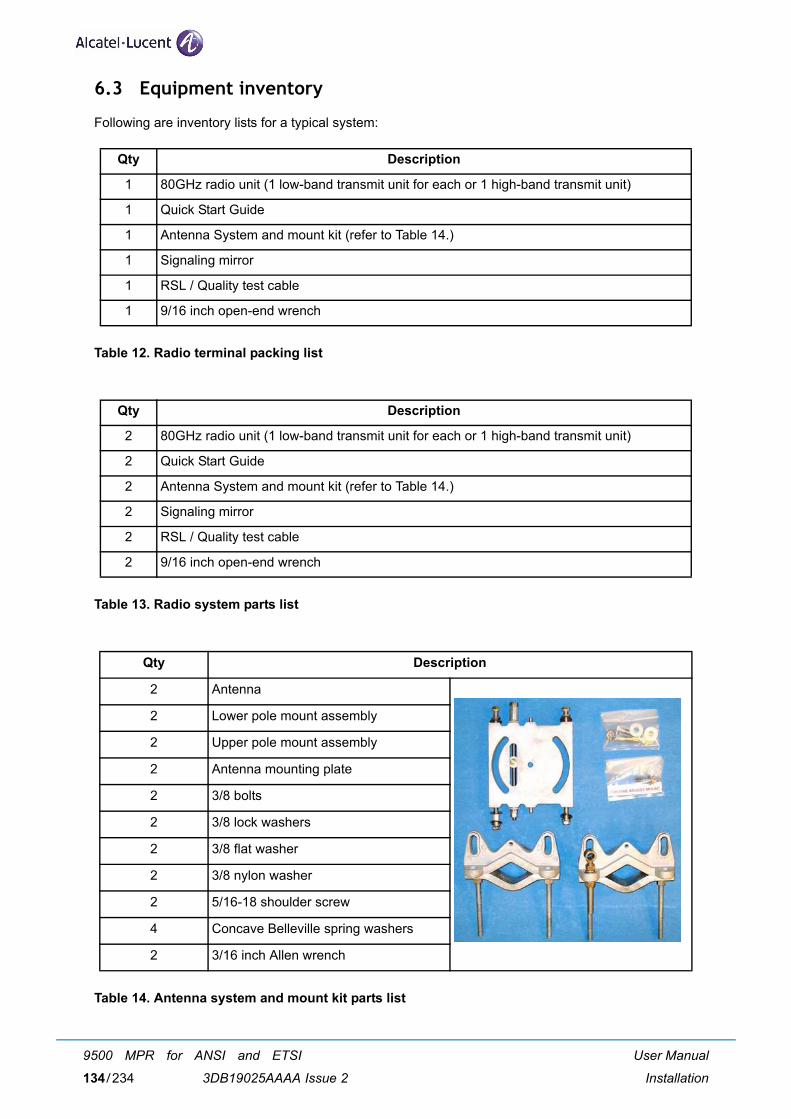
6.3 Equipment inventory
Following are inventory lists for a typical system:
Table 12. Radio terminal packing list
Table 13. Radio system parts list
Table 14. Antenna system and mount kit parts list
Qty Description
1 80GHz radio unit (1 low-band transmit unit for each or 1 high-band transmit unit)
1 Quick Start Guide
1 Antenna System and mount kit (refer to Table 14.)
1 Signaling mirror
1 RSL / Quality test cable
1 9/16 inch open-end wrench
Qty Description
2 80GHz radio unit (1 low-band transmit unit for each or 1 high-band transmit unit)
2 Quick Start Guide
2 Antenna System and mount kit (refer to Table 14.)
2 Signaling mirror
2 RSL / Quality test cable
2 9/16 inch open-end wrench
Qty Description
2 Antenna
2 Lower pole mount assembly
2 Upper pole mount assembly
2 Antenna mounting plate
2 3/8 bolts
2 3/8 lock washers
2 3/8 flat washer
2 3/8 nylon washer
2 5/16-18 shoulder screw
4 Concave Belleville spring washers
2 3/16 inch Allen wrench
User Manual
Installation
9500 MPR for ANSI and ETSI
3DB19025AAAA Issue 2134/234

For more information on recommended accessory devices and spareparts, contact Alcatel-Lucent Sales.
The MPT-GC is sealed at the factory warranty stickers on the inner(metal) cover of the radio. There is no need to open this cover in the field.Tampering with these seals will void the warranty.
User Manual
Installation
9500 MPR for ANSI and ETSI
3DB19025AAAA Issue 2 135/234
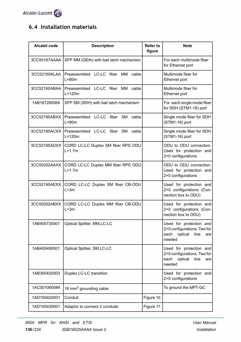
6.4 Installation materials
Alcatel code Description Refer to figure
Note
3CC50167AAAA SFP MM (GEth) with bail latch mechanism For each multimode fiberfor Ethernet port
3CC52160ALAA Preassembled LC-LC fiber MM cableL=80m
Multimode fiber for Ethernet port
3CC52160ABAA Preassembled LC-LC fiber MM cableL=120m
Multimode fiber for Ethernet port
1AB187280064 SFP SM (SDH) with bail latch mechanism For each single mode fiberfor SDH (STM1-16) port
3CC52195ABXX Preassembled LC-LC fiber SM cableL=80m
Single mode fiber for SDH(STM1-16) port
3CC52195ACXX Preassembled LC-LC fiber SM cableL=120m
Single mode fiber for SDH(STM1-16) port
3CC52195ADXX CORD LC-LC Duplex SM fiber RPS ODUL=1.7m
ODU to ODU connection.Used for protection and2+0 configurations
3CC50202AAXX CORD LC-LC Duplex MM fiber RPS ODUL=1.7m
ODU to ODU connection.Used for protection and2+0 configurations
3CC52195AEXX CORD LC-LC Duplex SM fiber CB-ODUL=3m
Used for protection and2+0 configurations (Con-nection box to ODU)
3CC50202ABXX CORD LC-LC Duplex MM fiber CB-ODUL=3m
Used for protection and2+0 configurations (Con-nection box to ODU)
1AB405730001 Optical Splitter, MM,LC-LC Used for protection and2+0 configurations. Two foreach optical line areneeded
1AB405480001 Optical Splitter, SM,LC-LC Used for protection and2+0 configurations. Two foreach optical line areneeded
1AB365420003 Duplex LC-LC transition Used for protection and2+0 configurations
1AC001060084 16 mm2 grounding cable To ground the MPT-GC
1AD100420001 Conduit Figure 10.
1AD100430001 Adaptor to connect 2 conduits Figure 11.
User Manual
Installation
9500 MPR for ANSI and ETSI
3DB19025AAAA Issue 2136/234
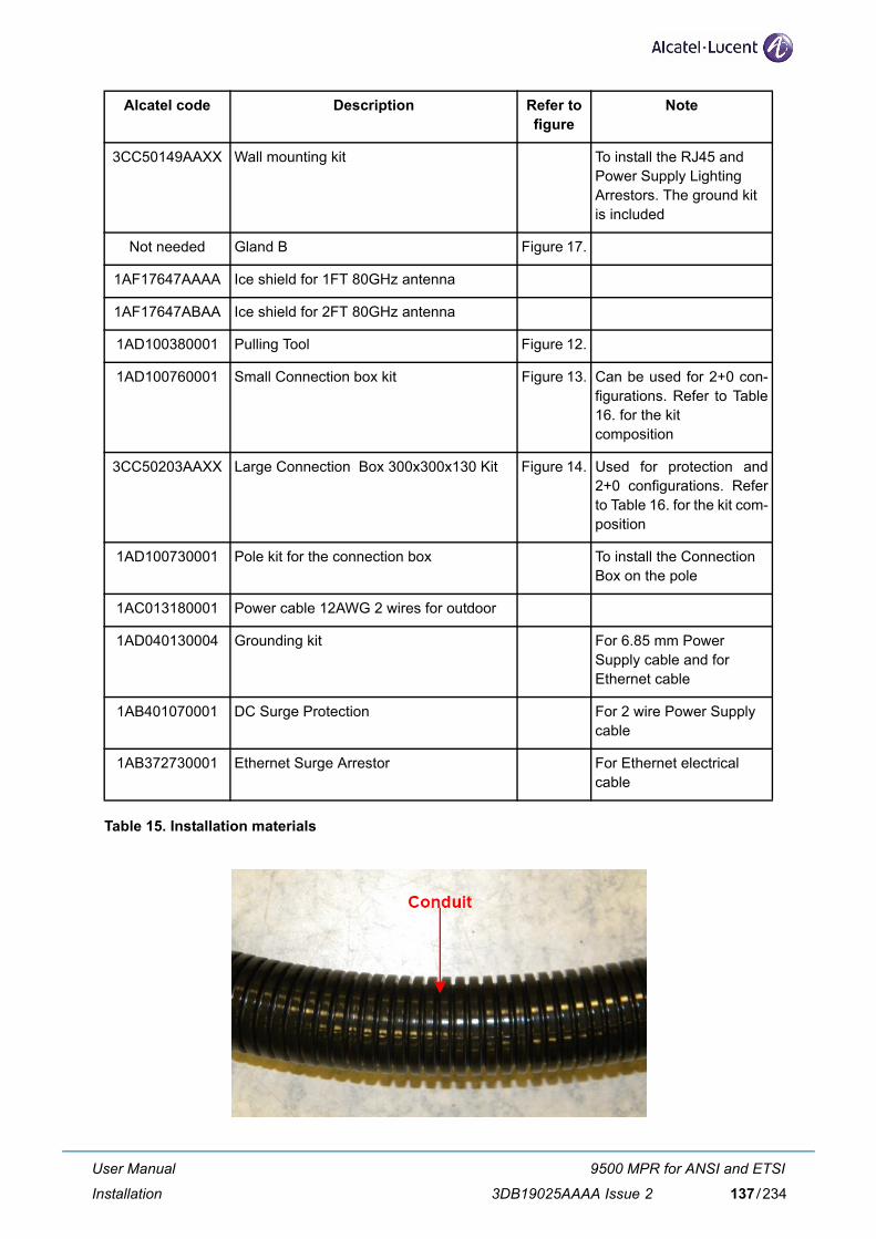
Table 15. Installation materials
3CC50149AAXX Wall mounting kit To install the RJ45 andPower Supply LightingArrestors. The ground kitis included
Not needed Gland B Figure 17.
1AF17647AAAA Ice shield for 1FT 80GHz antenna
1AF17647ABAA Ice shield for 2FT 80GHz antenna
1AD100380001 Pulling Tool Figure 12.
1AD100760001 Small Connection box kit Figure 13. Can be used for 2+0 con-figurations. Refer to Table16. for the kitcomposition
3CC50203AAXX Large Connection Box 300x300x130 Kit Figure 14. Used for protection and2+0 configurations. Referto Table 16. for the kit com-position
1AD100730001 Pole kit for the connection box To install the ConnectionBox on the pole
1AC013180001 Power cable 12AWG 2 wires for outdoor
1AD040130004 Grounding kit For 6.85 mm Power Supply cable and forEthernet cable
1AB401070001 DC Surge Protection For 2 wire Power Supplycable
1AB372730001 Ethernet Surge Arrestor For Ethernet electricalcable
Alcatel code Description Refer to figure
Note
User Manual
Installation
9500 MPR for ANSI and ETSI
3DB19025AAAA Issue 2 137/234
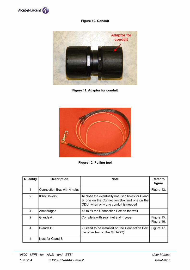
Figure 10. Conduit
Figure 11. Adaptor for conduit
Figure 12. Pulling tool
Quantity Description Note Refer to figure
1 Connection Box with 4 holes Figure 13.
2 IP66 Covers To close the eventually not used holes for GlandB, one on the Connection Box and one on theODU, when only one conduit is needed
4 Anchorages Kit to fix the Connection Box on the wall
2 Glands A Complete with seal, nut and 4 cups Figure 15.Figure 16.
4 Glands B 2 Gland to be installed on the Connection Box;the other two on the MPT-GC)
Figure 17.
4 Nuts for Gland B
User Manual
Installation
9500 MPR for ANSI and ETSI
3DB19025AAAA Issue 2138/234
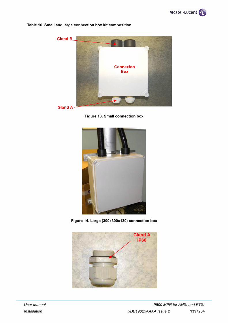
Table 16. Small and large connection box kit composition
Figure 13. Small connection box
Figure 14. Large (300x300x130) connection box
User Manual
Installation
9500 MPR for ANSI and ETSI
3DB19025AAAA Issue 2 139/234
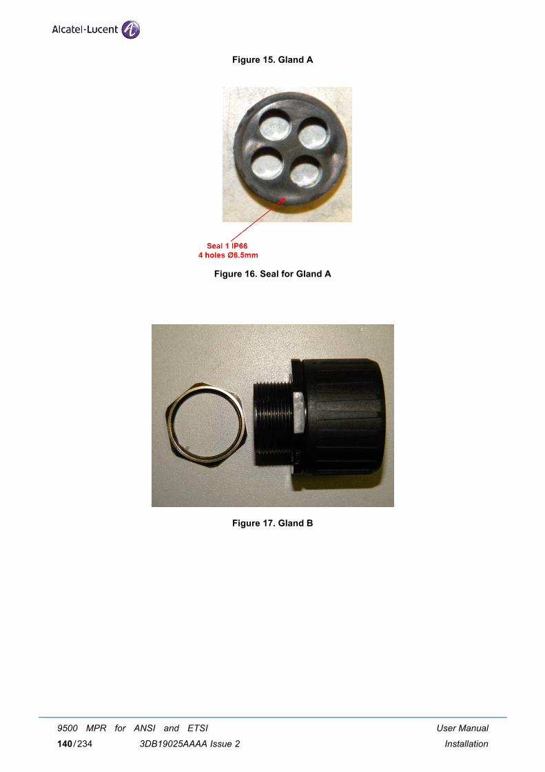
Figure 15. Gland A
Figure 16. Seal for Gland A
Figure 17. Gland B
User Manual
Installation
9500 MPR for ANSI and ETSI
3DB19025AAAA Issue 2140/234
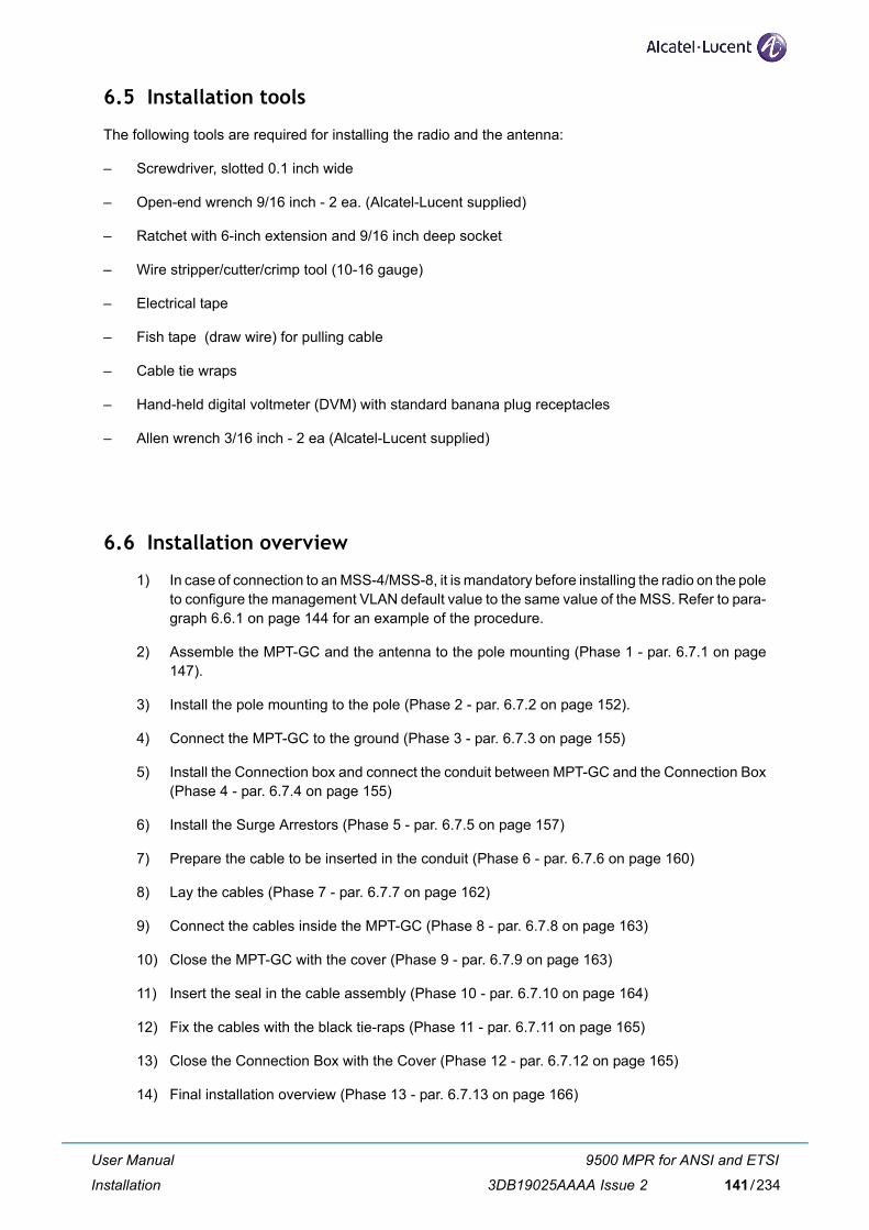
6.5 Installation tools
The following tools are required for installing the radio and the antenna:
– Screwdriver, slotted 0.1 inch wide
– Open-end wrench 9/16 inch - 2 ea. (Alcatel-Lucent supplied)
– Ratchet with 6-inch extension and 9/16 inch deep socket
– Wire stripper/cutter/crimp tool (10-16 gauge)
– Electrical tape
– Fish tape (draw wire) for pulling cable
– Cable tie wraps
– Hand-held digital voltmeter (DVM) with standard banana plug receptacles
– Allen wrench 3/16 inch - 2 ea (Alcatel-Lucent supplied)
6.6 Installation overview
1) In case of connection to an MSS-4/MSS-8, it is mandatory before installing the radio on the poleto configure the management VLAN default value to the same value of the MSS. Refer to para-graph 6.6.1 on page 144 for an example of the procedure.
2) Assemble the MPT-GC and the antenna to the pole mounting (Phase 1 - par. 6.7.1 on page147).
3) Install the pole mounting to the pole (Phase 2 - par. 6.7.2 on page 152).
4) Connect the MPT-GC to the ground (Phase 3 - par. 6.7.3 on page 155)
5) Install the Connection box and connect the conduit between MPT-GC and the Connection Box(Phase 4 - par. 6.7.4 on page 155)
6) Install the Surge Arrestors (Phase 5 - par. 6.7.5 on page 157)
7) Prepare the cable to be inserted in the conduit (Phase 6 - par. 6.7.6 on page 160)
8) Lay the cables (Phase 7 - par. 6.7.7 on page 162)
9) Connect the cables inside the MPT-GC (Phase 8 - par. 6.7.8 on page 163)
10) Close the MPT-GC with the cover (Phase 9 - par. 6.7.9 on page 163)
11) Insert the seal in the cable assembly (Phase 10 - par. 6.7.10 on page 164)
12) Fix the cables with the black tie-raps (Phase 11 - par. 6.7.11 on page 165)
13) Close the Connection Box with the Cover (Phase 12 - par. 6.7.12 on page 165)
14) Final installation overview (Phase 13 - par. 6.7.13 on page 166)
User Manual
Installation
9500 MPR for ANSI and ETSI
3DB19025AAAA Issue 2 141/234
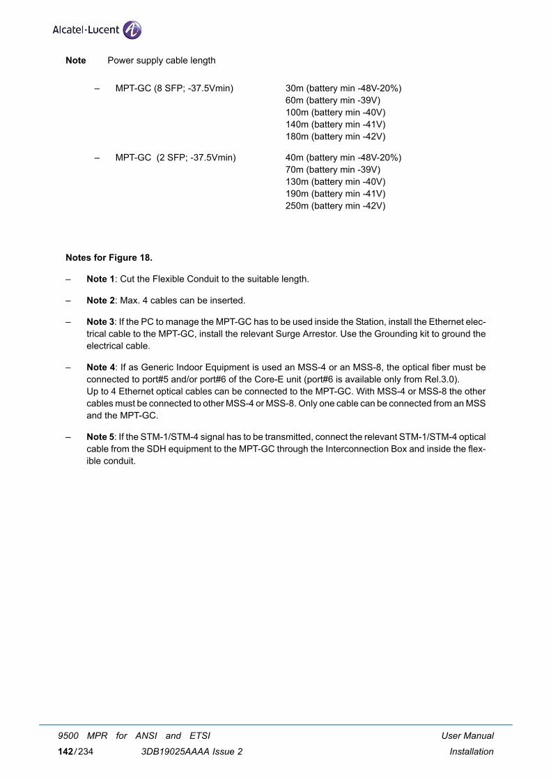
Note Power supply cable length
Notes for Figure 18.
– Note 1: Cut the Flexible Conduit to the suitable length.
– Note 2: Max. 4 cables can be inserted.
– Note 3: If the PC to manage the MPT-GC has to be used inside the Station, install the Ethernet elec-trical cable to the MPT-GC, install the relevant Surge Arrestor. Use the Grounding kit to ground theelectrical cable.
– Note 4: If as Generic Indoor Equipment is used an MSS-4 or an MSS-8, the optical fiber must beconnected to port#5 and/or port#6 of the Core-E unit (port#6 is available only from Rel.3.0).Up to 4 Ethernet optical cables can be connected to the MPT-GC. With MSS-4 or MSS-8 the othercables must be connected to other MSS-4 or MSS-8. Only one cable can be connected from an MSSand the MPT-GC.
– Note 5: If the STM-1/STM-4 signal has to be transmitted, connect the relevant STM-1/STM-4 opticalcable from the SDH equipment to the MPT-GC through the Interconnection Box and inside the flex-ible conduit.
– MPT-GC (8 SFP; -37.5Vmin) 30m (battery min -48V-20%)60m (battery min -39V)100m (battery min -40V)140m (battery min -41V)180m (battery min -42V)
– MPT-GC (2 SFP; -37.5Vmin) 40m (battery min -48V-20%)70m (battery min -39V)130m (battery min -40V)190m (battery min -41V)250m (battery min -42V)
User Manual
Installation
9500 MPR for ANSI and ETSI
3DB19025AAAA Issue 2142/234
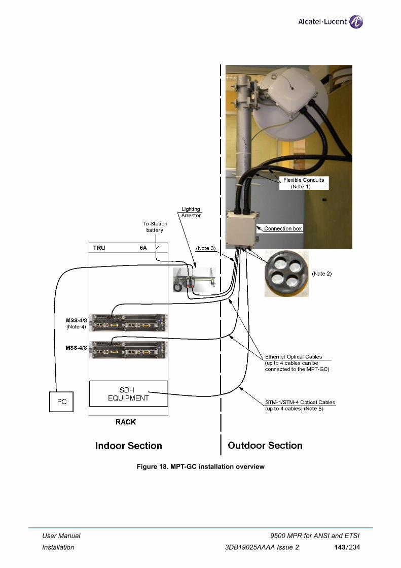
Figure 18. MPT-GC installation overview
User Manual
Installation
9500 MPR for ANSI and ETSI
3DB19025AAAA Issue 2 143/234
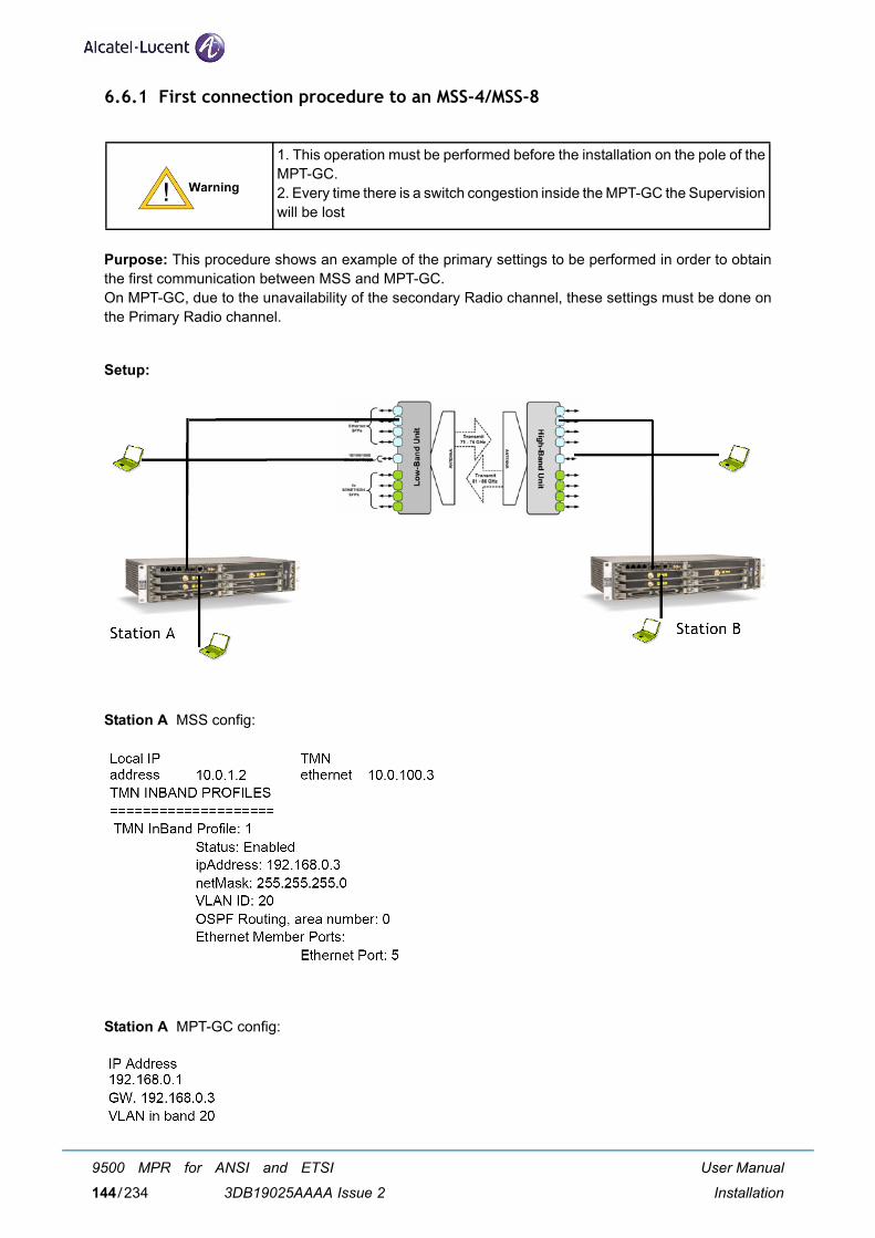
6.6.1 First connection procedure to an MSS-4/MSS-8
Purpose: This procedure shows an example of the primary settings to be performed in order to obtainthe first communication between MSS and MPT-GC. On MPT-GC, due to the unavailability of the secondary Radio channel, these settings must be done onthe Primary Radio channel.
Setup:
Station A MSS config:
Station A MPT-GC config:
1. This operation must be performed before the installation on the pole of theMPT-GC.2. Every time there is a switch congestion inside the MPT-GC the Supervisionwill be lost
User Manual
Installation
9500 MPR for ANSI and ETSI
3DB19025AAAA Issue 2144/234
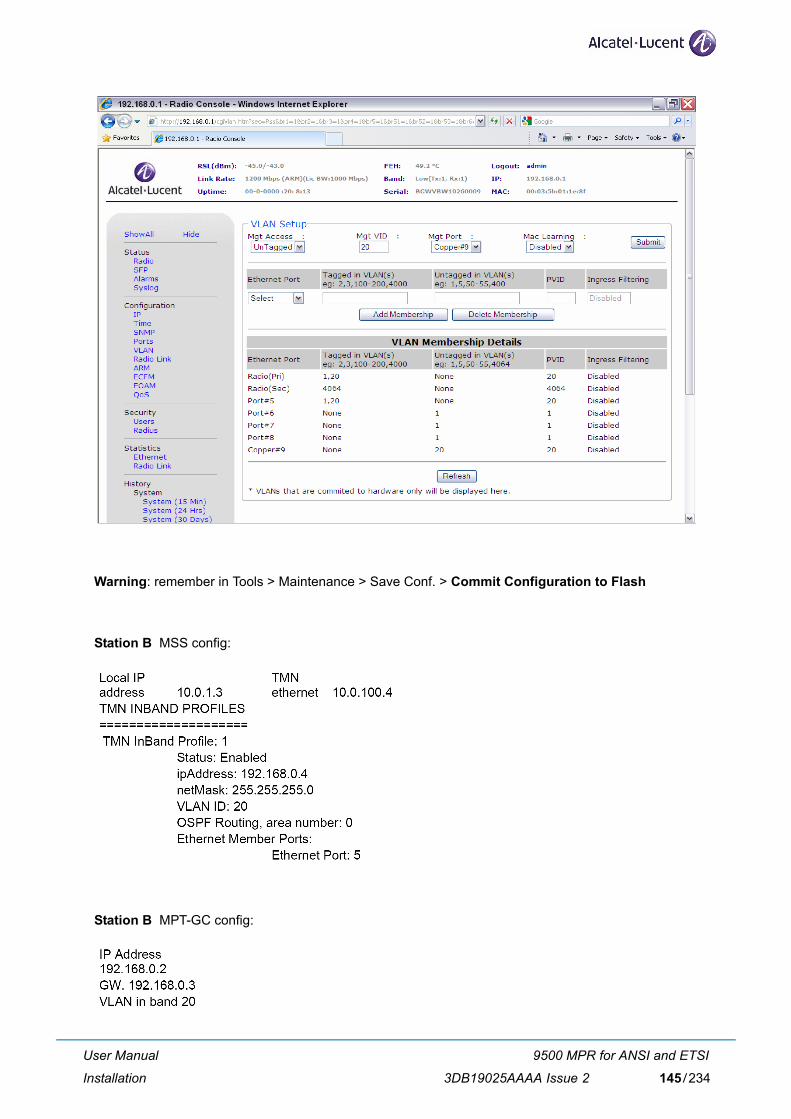
Warning: remember in Tools > Maintenance > Save Conf. > Commit Configuration to Flash
Station B MSS config:
Station B MPT-GC config:
User Manual
Installation
9500 MPR for ANSI and ETSI
3DB19025AAAA Issue 2 145/234
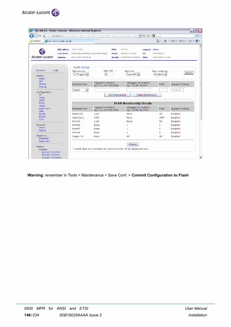
Warning: remember in Tools > Maintenance > Save Conf. > Commit Configuration to Flash
User Manual
Installation
9500 MPR for ANSI and ETSI
3DB19025AAAA Issue 2146/234
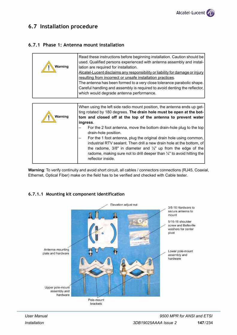
6.7 Installation procedure
6.7.1 Phase 1: Antenna mount installation
Warning: To verify continuity and avoid short circuit, all cables / connectors connections (RJ45, Coaxial,Ethernet, Optical Fiber) make on the field has to be verified and checked with Cable tester.
6.7.1.1 Mounting kit component identification
Read these instructions before beginning installation. Caution should beused. Qualified persons experienced with antenna assembly and instal-lation are required for installation.Alcatel-Lucent disclaims any responsibility or liability for damage or injuryresulting from incorrect or unsafe installation practices.The antenna has been formed to a very close tolerance parabolic shape.Careful handling and assembly is required to avoid denting the reflector,which would degrade antenna performance.
When using the left side radio mount position, the antenna ends up get-ting rotated by 180 degrees. The drain hole must be open at the bot-tom and closed off at the top of the antenna to prevent wateringress. – For the 2 foot antenna, move the bottom drain-hole plug to the top
drain-hole position.– For the 1 foot antenna, plug the original drain hole using common,
industrial RTV sealant. Then drill a new drain hole at the bottom, ofthe radome, 3/8" in diameter and ½" up from the edge of theradome, making sure not to drill deeper than ¼" to avoid hitting thereflector inside.
User Manual
Installation
9500 MPR for ANSI and ETSI
3DB19025AAAA Issue 2 147/234
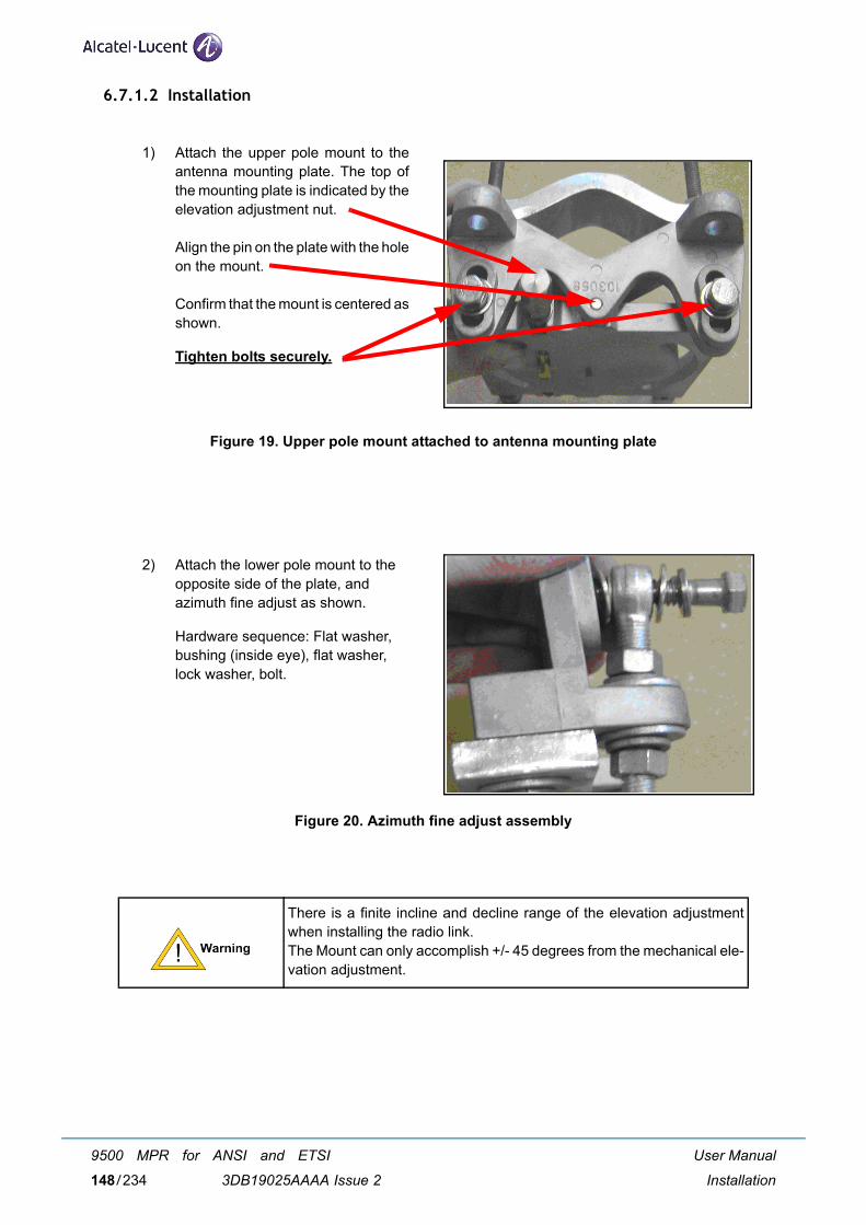
6.7.1.2 Installation
Figure 19. Upper pole mount attached to antenna mounting plate
Figure 20. Azimuth fine adjust assembly
There is a finite incline and decline range of the elevation adjustmentwhen installing the radio link. The Mount can only accomplish +/- 45 degrees from the mechanical ele-vation adjustment.
1) Attach the upper pole mount to theantenna mounting plate. The top ofthe mounting plate is indicated by theelevation adjustment nut.
Align the pin on the plate with the holeon the mount.
Confirm that the mount is centered asshown.
Tighten bolts securely.
2) Attach the lower pole mount to theopposite side of the plate, and azimuth fine adjust as shown.
Hardware sequence: Flat washer,bushing (inside eye), flat washer, lock washer, bolt.
User Manual
Installation
9500 MPR for ANSI and ETSI
3DB19025AAAA Issue 2148/234
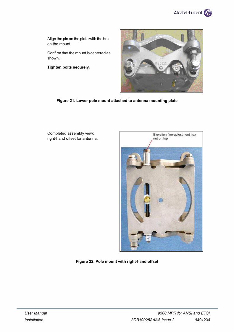
Figure 21. Lower pole mount attached to antenna mounting plate
Figure 22. Pole mount with right-hand offset
Align the pin on the plate with the holeon the mount.
Confirm that the mount is centered asshown.
Tighten bolts securely.
Completed assembly view: right-hand offset for antenna.
User Manual
Installation
9500 MPR for ANSI and ETSI
3DB19025AAAA Issue 2 149/234
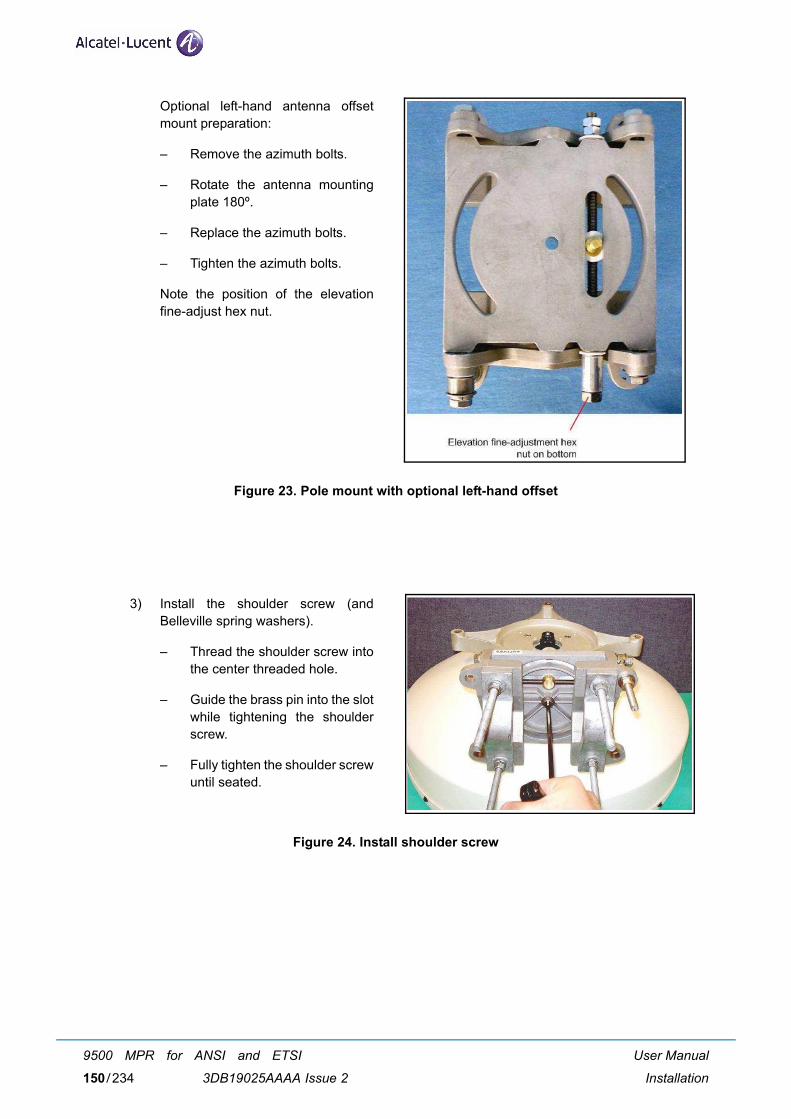
Figure 23. Pole mount with optional left-hand offset
Figure 24. Install shoulder screw
Optional left-hand antenna offsetmount preparation:
– Remove the azimuth bolts.
– Rotate the antenna mountingplate 180º.
– Replace the azimuth bolts.
– Tighten the azimuth bolts.
Note the position of the elevationfine-adjust hex nut.
3) Install the shoulder screw (andBelleville spring washers).
– Thread the shoulder screw intothe center threaded hole.
– Guide the brass pin into the slotwhile tightening the shoulderscrew.
– Fully tighten the shoulder screwuntil seated.
User Manual
Installation
9500 MPR for ANSI and ETSI
3DB19025AAAA Issue 2150/234
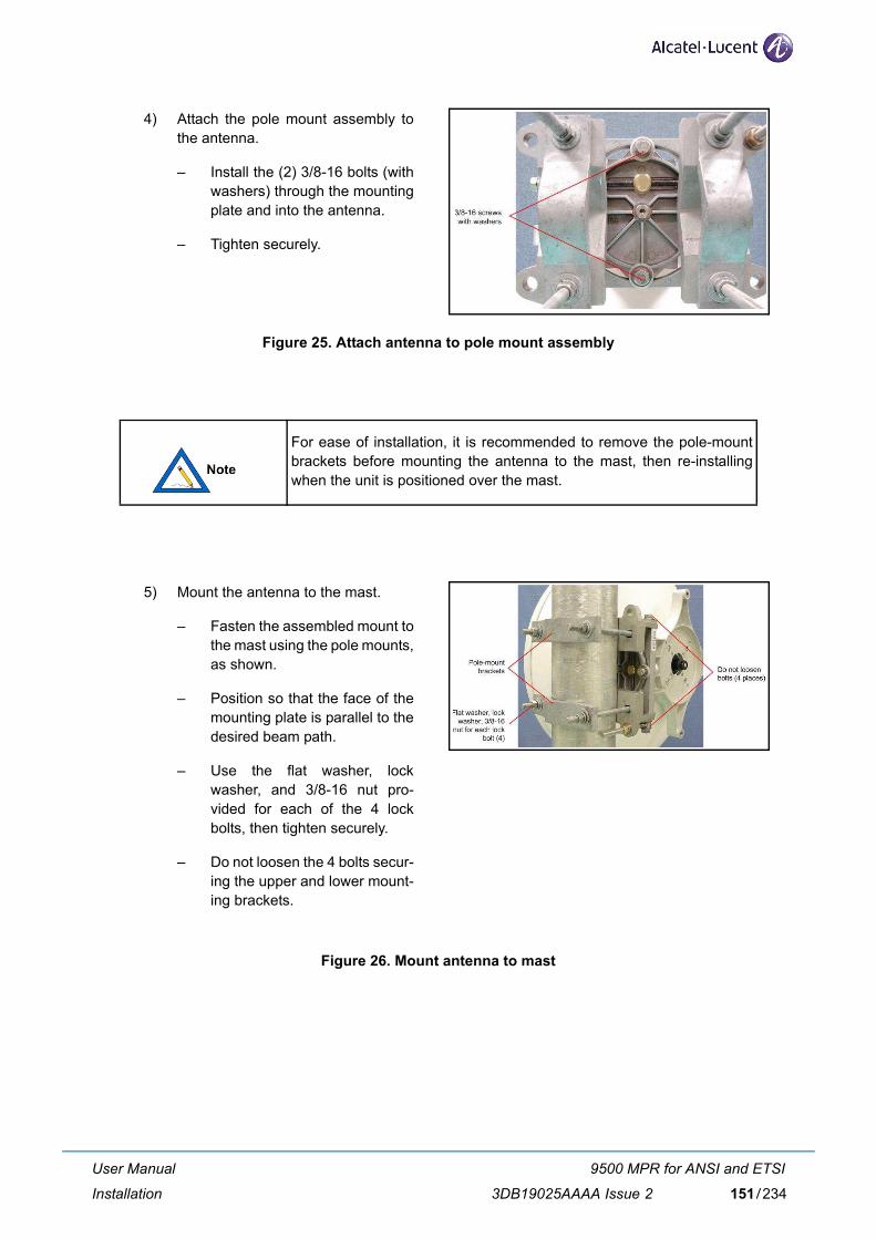
Figure 25. Attach antenna to pole mount assembly
Figure 26. Mount antenna to mast
For ease of installation, it is recommended to remove the pole-mountbrackets before mounting the antenna to the mast, then re-installingwhen the unit is positioned over the mast.
4) Attach the pole mount assembly tothe antenna.
– Install the (2) 3/8-16 bolts (withwashers) through the mountingplate and into the antenna.
– Tighten securely.
5) Mount the antenna to the mast.
– Fasten the assembled mount tothe mast using the pole mounts,as shown.
– Position so that the face of themounting plate is parallel to thedesired beam path.
– Use the flat washer, lockwasher, and 3/8-16 nut pro-vided for each of the 4 lockbolts, then tighten securely.
– Do not loosen the 4 bolts secur-ing the upper and lower mount-ing brackets.
User Manual
Installation
9500 MPR for ANSI and ETSI
3DB19025AAAA Issue 2 151/234
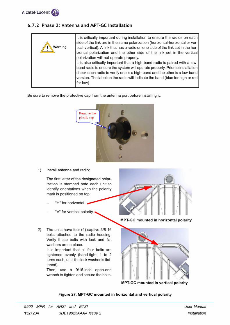
6.7.2 Phase 2: Antenna and MPT-GC installation
Be sure to remove the protective cap from the antenna port before installing it:
Figure 27. MPT-GC mounted in horizontal and vertical polarity
It is critically important during installation to ensure the radios on eachside of the link are in the same polarization (horizontal-horizontal or ver-tical-vertical). A link that has a radio on one side of the link set in the hor-izontal polarization and the other side of the link set in the verticalpolarization will not operate properly.It is also critically important that a high-band radio is paired with a low-band radio to ensure the system will operate properly. Prior to installationcheck each radio to verify one is a high-band and the other is a low-bandversion. The label on the radio will indicate the band (blue for high or redfor low).
1) Install antenna and radio:
The first letter of the designated polar-ization is stamped onto each unit toidentify orientations when the polaritymark is positioned on top:
– "H" for horizontal.
– "V" for vertical polarity.
2) The units have four (4) captive 3/8-16bolts attached to the radio housing.Verify these bolts with lock and flatwashers are in place. It is important that all four bolts aretightened evenly (hand-tight, 1 to 2turns each, until the lock washer is flat-tened).Then, use a 9/16-inch open-endwrench to tighten and secure the bolts.
MPT-GC mounted in horizontal polarity
MPT-GC mounted in vertical polarity
User Manual
Installation
9500 MPR for ANSI and ETSI
3DB19025AAAA Issue 2152/234
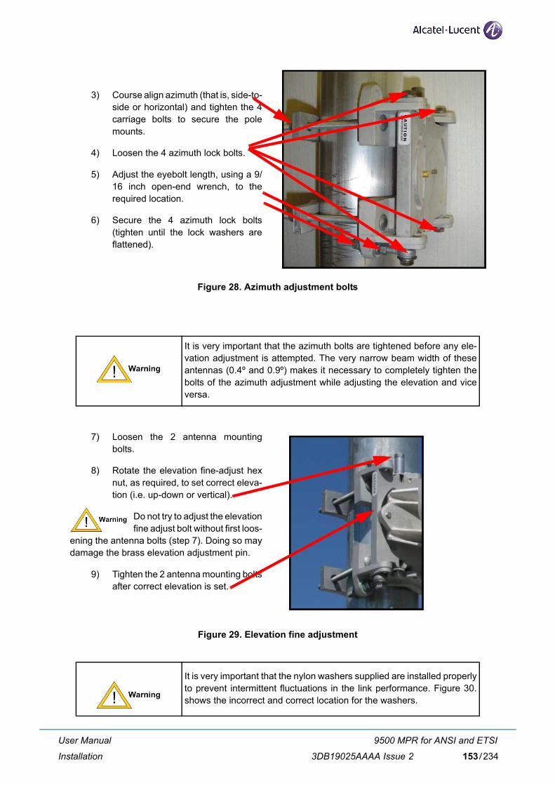
Figure 28. Azimuth adjustment bolts
Figure 29. Elevation fine adjustment
It is very important that the azimuth bolts are tightened before any ele-vation adjustment is attempted. The very narrow beam width of theseantennas (0.4º and 0.9º) makes it necessary to completely tighten thebolts of the azimuth adjustment while adjusting the elevation and viceversa.
It is very important that the nylon washers supplied are installed properlyto prevent intermittent fluctuations in the link performance. Figure 30.shows the incorrect and correct location for the washers.
3) Course align azimuth (that is, side-to-side or horizontal) and tighten the 4carriage bolts to secure the polemounts.
4) Loosen the 4 azimuth lock bolts.
5) Adjust the eyebolt length, using a 9/16 inch open-end wrench, to therequired location.
6) Secure the 4 azimuth lock bolts(tighten until the lock washers areflattened).
7) Loosen the 2 antenna mountingbolts.
8) Rotate the elevation fine-adjust hexnut, as required, to set correct eleva-tion (i.e. up-down or vertical).
Do not try to adjust the elevationfine adjust bolt without first loos-
ening the antenna bolts (step 7). Doing so maydamage the brass elevation adjustment pin.
9) Tighten the 2 antenna mounting boltsafter correct elevation is set.
User Manual
Installation
9500 MPR for ANSI and ETSI
3DB19025AAAA Issue 2 153/234
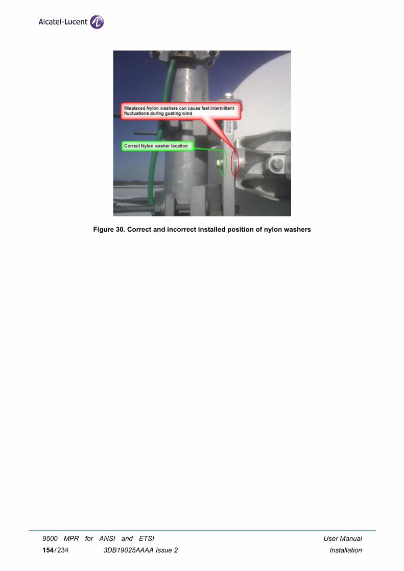
Figure 30. Correct and incorrect installed position of nylon washers
User Manual
Installation
9500 MPR for ANSI and ETSI
3DB19025AAAA Issue 2154/234
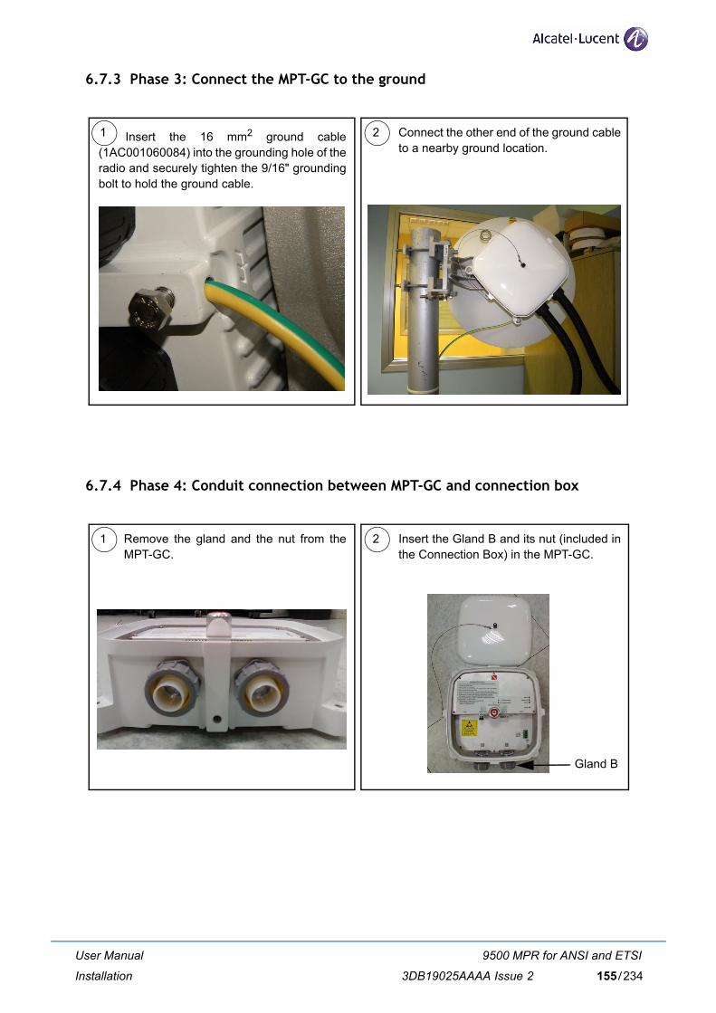
6.7.3 Phase 3: Connect the MPT-GC to the ground
6.7.4 Phase 4: Conduit connection between MPT-GC and connection box
1 2Insert the 16 mm2 ground cable(1AC001060084) into the grounding hole of theradio and securely tighten the 9/16" groundingbolt to hold the ground cable.
Connect the other end of the ground cableto a nearby ground location.
1 2Remove the gland and the nut from theMPT-GC.
Insert the Gland B and its nut (included inthe Connection Box) in the MPT-GC.
Gland B
User Manual
Installation
9500 MPR for ANSI and ETSI
3DB19025AAAA Issue 2 155/234
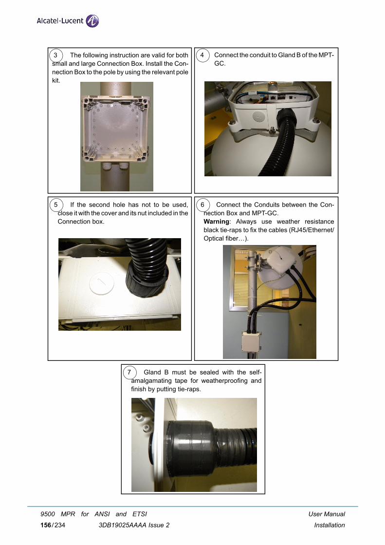
5 6 Connect the Conduits between the Con-nection Box and MPT-GC.Warning: Always use weather resistanceblack tie-raps to fix the cables (RJ45/Ethernet/Optical fiber…).
If the second hole has not to be used,close it with the cover and its nut included in theConnection box.
7 Gland B must be sealed with the self-amalgamating tape for weatherproofing andfinish by putting tie-raps.
3 The following instruction are valid for bothsmall and large Connection Box. Install the Con-nection Box to the pole by using the relevant polekit.
4 Connect the conduit to Gland B of the MPT-GC.
User Manual
Installation
9500 MPR for ANSI and ETSI
3DB19025AAAA Issue 2156/234
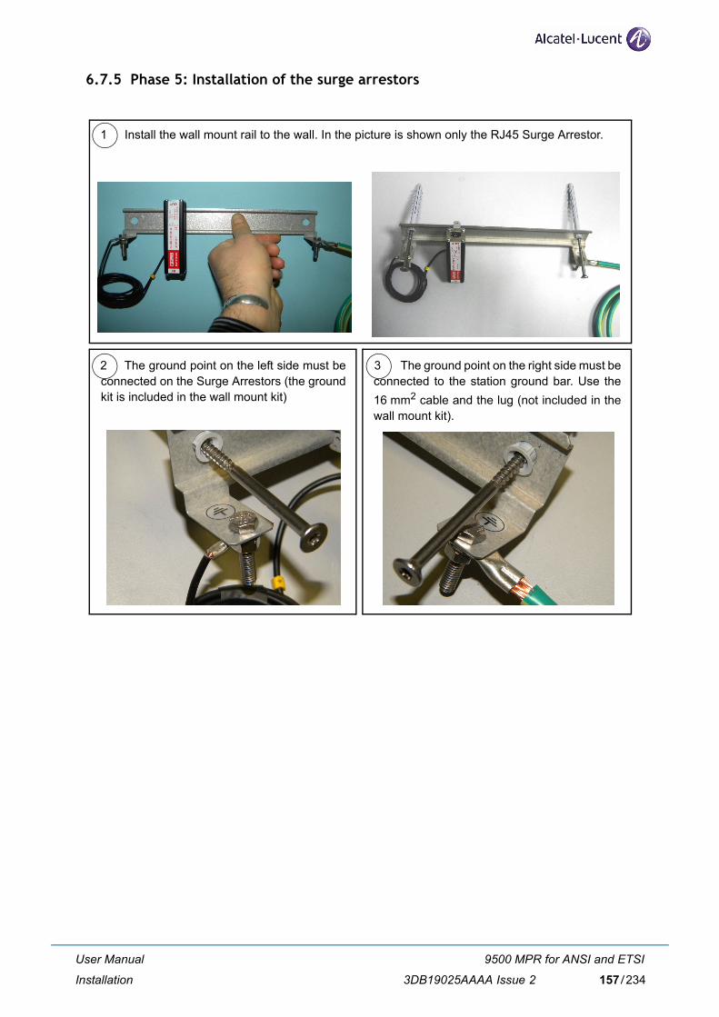
6.7.5 Phase 5: Installation of the surge arrestors
2 The ground point on the left side must beconnected on the Surge Arrestors (the groundkit is included in the wall mount kit)
The ground point on the right side must beconnected to the station ground bar. Use the16 mm2 cable and the lug (not included in thewall mount kit).
1 Install the wall mount rail to the wall. In the picture is shown only the RJ45 Surge Arrestor.
3
User Manual
Installation
9500 MPR for ANSI and ETSI
3DB19025AAAA Issue 2 157/234
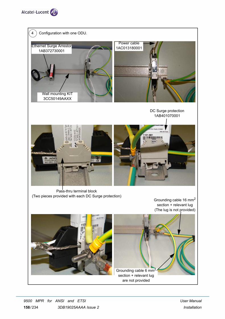
4 Configuration with one ODU.
Ethernet Surge Arrestor1AB372730001
Wall mounting KIT3CC50149AAXX
Power cable1AC013180001
Pass-thru terminal block(Two pieces provided with each DC Surge protection)
DC Surge protection1AB401070001
Grounding cable 16 mm2 section + relevant lug
(The lug is not provided)
Grounding cable 6 mm2 section + relevant lug
are not provided
User Manual
Installation
9500 MPR for ANSI and ETSI
3DB19025AAAA Issue 2158/234
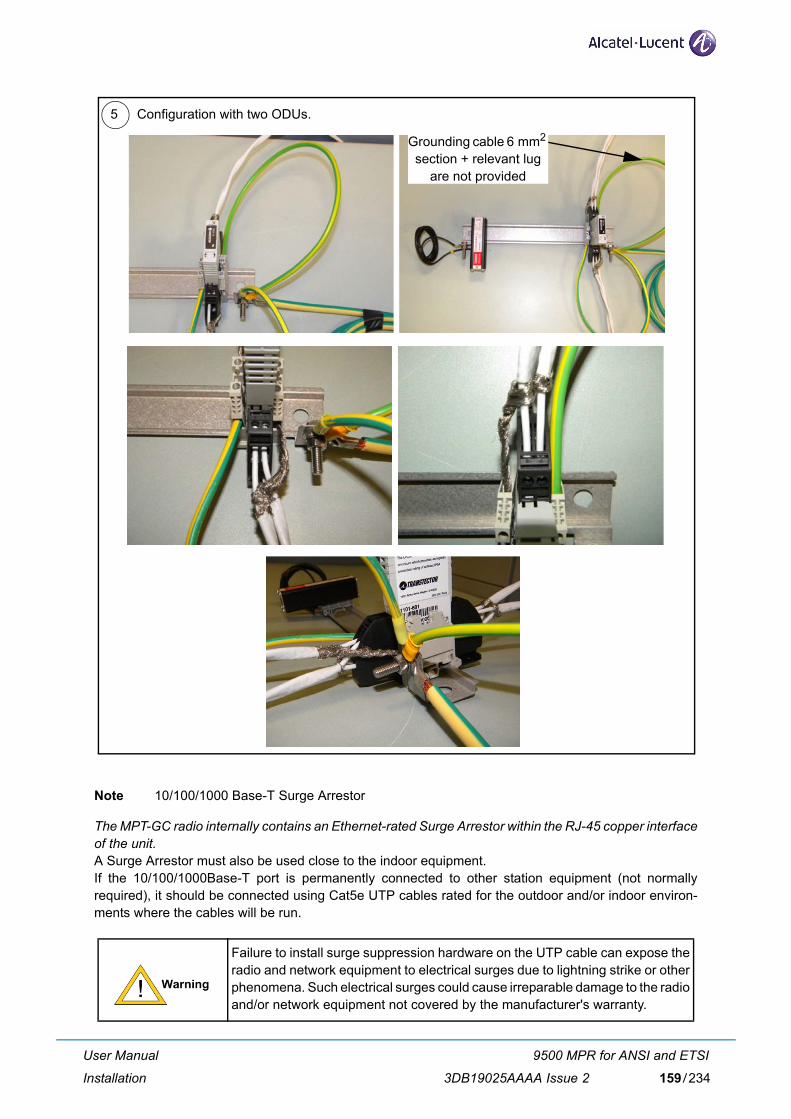
Note 10/100/1000 Base-T Surge Arrestor
The MPT-GC radio internally contains an Ethernet-rated Surge Arrestor within the RJ-45 copper interfaceof the unit. A Surge Arrestor must also be used close to the indoor equipment. If the 10/100/1000Base-T port is permanently connected to other station equipment (not normallyrequired), it should be connected using Cat5e UTP cables rated for the outdoor and/or indoor environ-ments where the cables will be run.
Failure to install surge suppression hardware on the UTP cable can expose theradio and network equipment to electrical surges due to lightning strike or otherphenomena. Such electrical surges could cause irreparable damage to the radioand/or network equipment not covered by the manufacturer's warranty.
5 Configuration with two ODUs.
Grounding cable 6 mm2 section + relevant lug
are not provided
User Manual
Installation
9500 MPR for ANSI and ETSI
3DB19025AAAA Issue 2 159/234
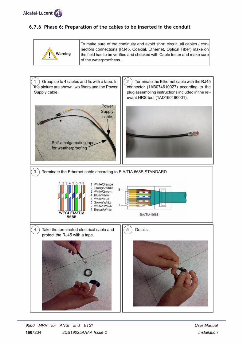
6.7.6 Phase 6: Preparation of the cables to be inserted in the conduit
To make sure of the continuity and avoid short circuit, all cables / con-nectors connections (RJ45, Coaxial, Ethernet, Optical Fiber) make onthe field has to be verified and checked with Cable tester and make sureof the waterproofness.
1 2Group up to 4 cables and fix with a tape. Inthe picture are shown two fibers and the PowerSupply cable.
Terminate the Ethernet cable with the RJ45connector (1AB074610027) according to theplug assembling instructions included in the rel-evant HRS tool (1AD160490001).
Self-amalgamating tapefor weatherproofing
Power Supplycable
3 Terminate the Ethernet cable according to EIA/TIA 568B STANDARD
4 5Take the terminated electrical cable andprotect the RJ45 with a tape.
Details.
User Manual
Installation
9500 MPR for ANSI and ETSI
3DB19025AAAA Issue 2160/234
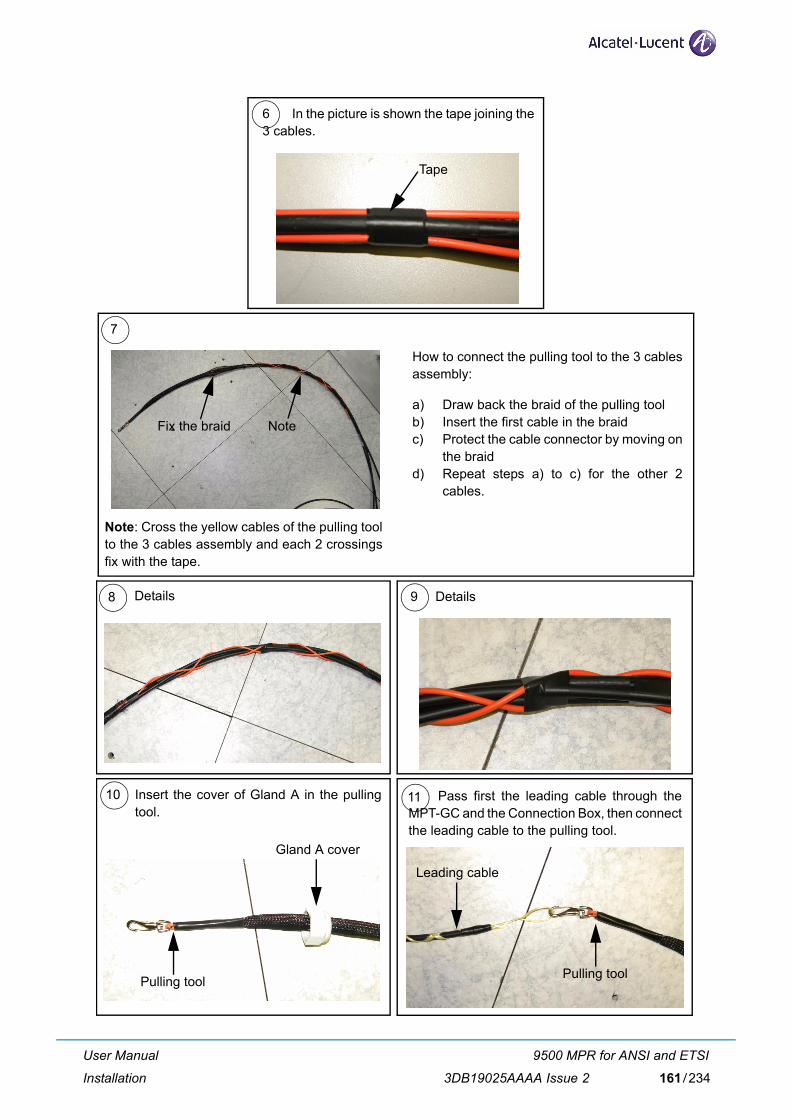
7
How to connect the pulling tool to the 3 cablesassembly:
a) Draw back the braid of the pulling toolb) Insert the first cable in the braidc) Protect the cable connector by moving on
the braidd) Repeat steps a) to c) for the other 2
cables.
6 In the picture is shown the tape joining the3 cables.
Tape
Fix the braid Note
Note: Cross the yellow cables of the pulling toolto the 3 cables assembly and each 2 crossingsfix with the tape.
Details 9 Details8
Pass first the leading cable through theMPT-GC and the Connection Box, then connectthe leading cable to the pulling tool.
10 Insert the cover of Gland A in the pullingtool.
11
Pulling tool
Gland A cover
Leading cable
Pulling tool
User Manual
Installation
9500 MPR for ANSI and ETSI
3DB19025AAAA Issue 2 161/234
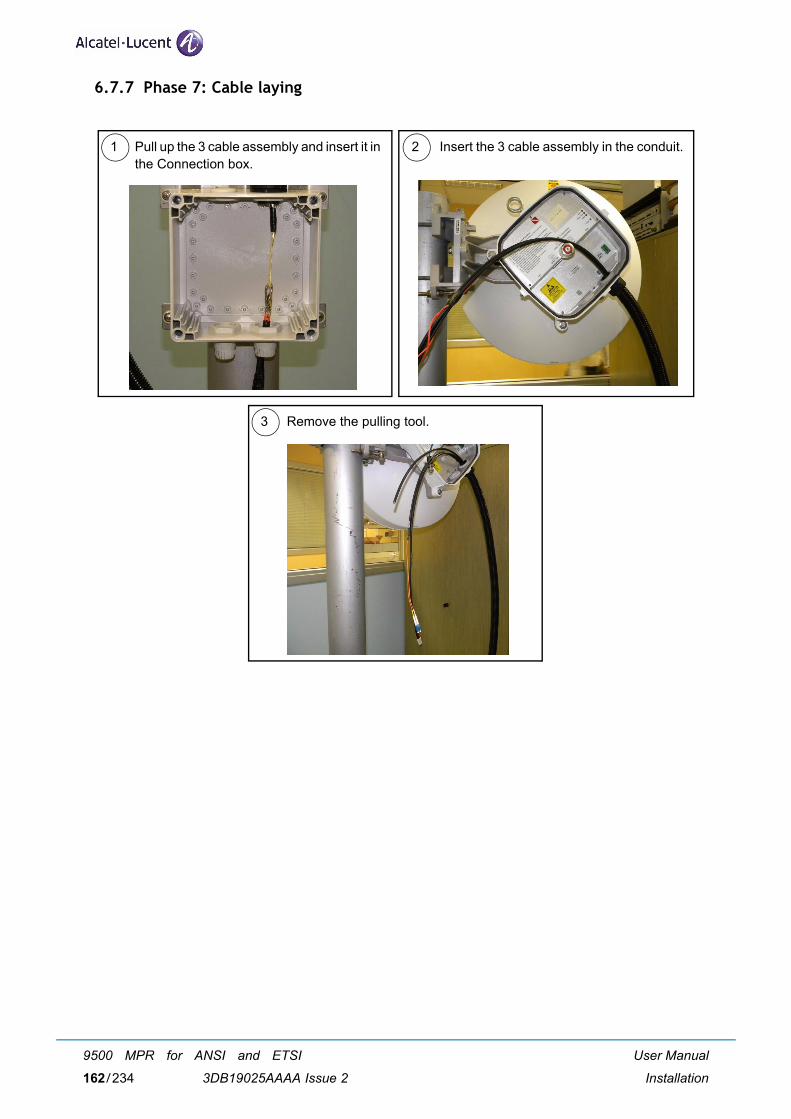
6.7.7 Phase 7: Cable laying
1 2
3
Pull up the 3 cable assembly and insert it inthe Connection box.
Insert the 3 cable assembly in the conduit.
Remove the pulling tool.
User Manual
Installation
9500 MPR for ANSI and ETSI
3DB19025AAAA Issue 2162/234
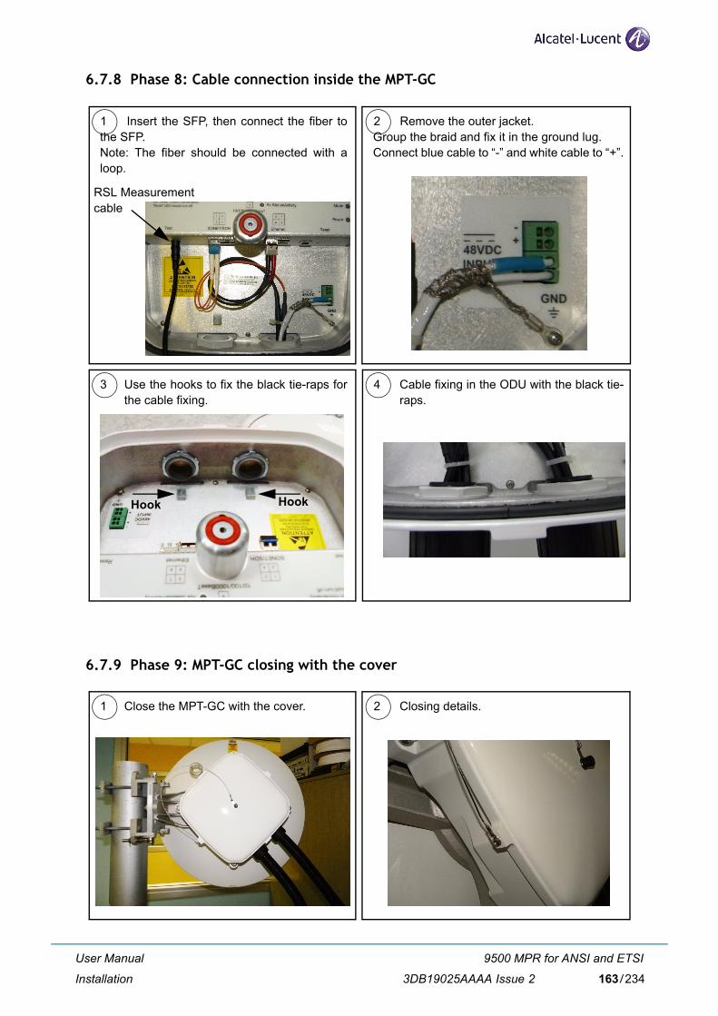
6.7.8 Phase 8: Cable connection inside the MPT-GC
6.7.9 Phase 9: MPT-GC closing with the cover
1 2Insert the SFP, then connect the fiber tothe SFP. Note: The fiber should be connected with aloop.
Remove the outer jacket.Group the braid and fix it in the ground lug.Connect blue cable to “-” and white cable to “+”.
3 4Use the hooks to fix the black tie-raps forthe cable fixing.
Cable fixing in the ODU with the black tie-raps.
Hook Hook
RSL Measurementcable
1 2Close the MPT-GC with the cover. Closing details.
User Manual
Installation
9500 MPR for ANSI and ETSI
3DB19025AAAA Issue 2 163/234
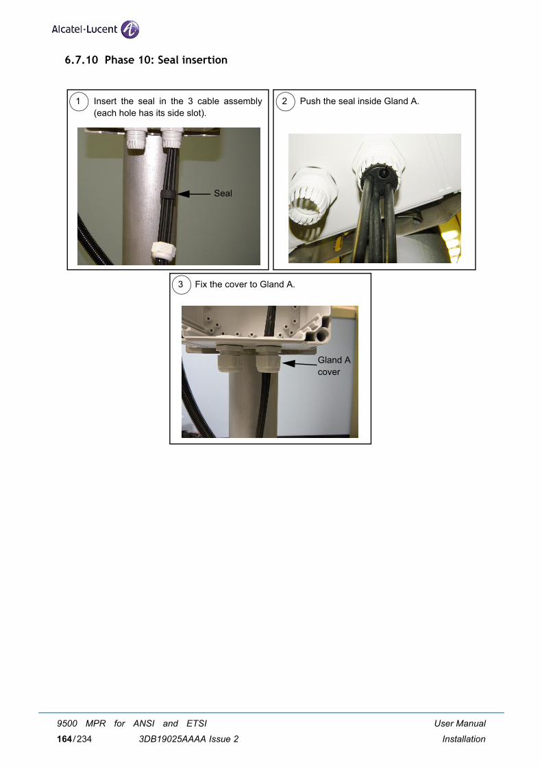
6.7.10 Phase 10: Seal insertion
1 2
3
Insert the seal in the 3 cable assembly(each hole has its side slot).
Push the seal inside Gland A.
Fix the cover to Gland A.
Seal
Gland Acover
User Manual
Installation
9500 MPR for ANSI and ETSI
3DB19025AAAA Issue 2164/234
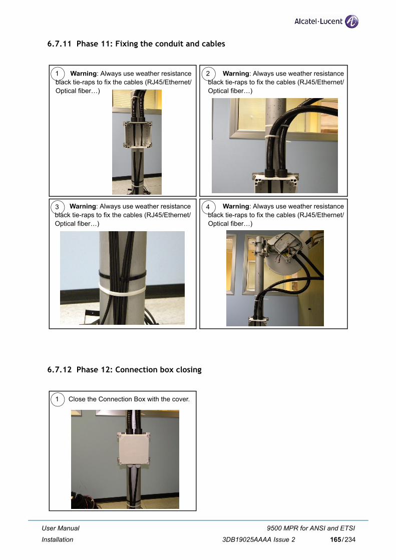
6.7.11 Phase 11: Fixing the conduit and cables
6.7.12 Phase 12: Connection box closing
Warning: Always use weather resistanceblack tie-raps to fix the cables (RJ45/Ethernet/Optical fiber…)
Warning: Always use weather resistanceblack tie-raps to fix the cables (RJ45/Ethernet/Optical fiber…)
1 2
3 4
Warning: Always use weather resistanceblack tie-raps to fix the cables (RJ45/Ethernet/Optical fiber…)
Warning: Always use weather resistanceblack tie-raps to fix the cables (RJ45/Ethernet/Optical fiber…)
1 Close the Connection Box with the cover.
User Manual
Installation
9500 MPR for ANSI and ETSI
3DB19025AAAA Issue 2 165/234

6.7.13 Phase 13: Final installation
6.7.14 Phase 14: Antenna rough-alignment
1) Loosen the pole-mount brackets enough to allow you to swing the unit horizontally.
2) Reference Chapter 6.7.1 for an illustration of antenna-mount bolts and their purpose.
3) Set the radio terminal to the pre-defined azimuth if available. If not, use binoculars or signal mir-ror to locate the far-end radio location.
4) If you can see the far-end radio terminal, estimate the alignment visually and tighten the polemount brackets with fine adjustment bolt set to the middle of adjustment range.
5) Ensure the horizontal adjustment bolts are snug; only tighten bolts one quarter of a turn.
1 Here a picture of the outdoor-side finalinstallation.
User Manual
Installation
9500 MPR for ANSI and ETSI
3DB19025AAAA Issue 2166/234
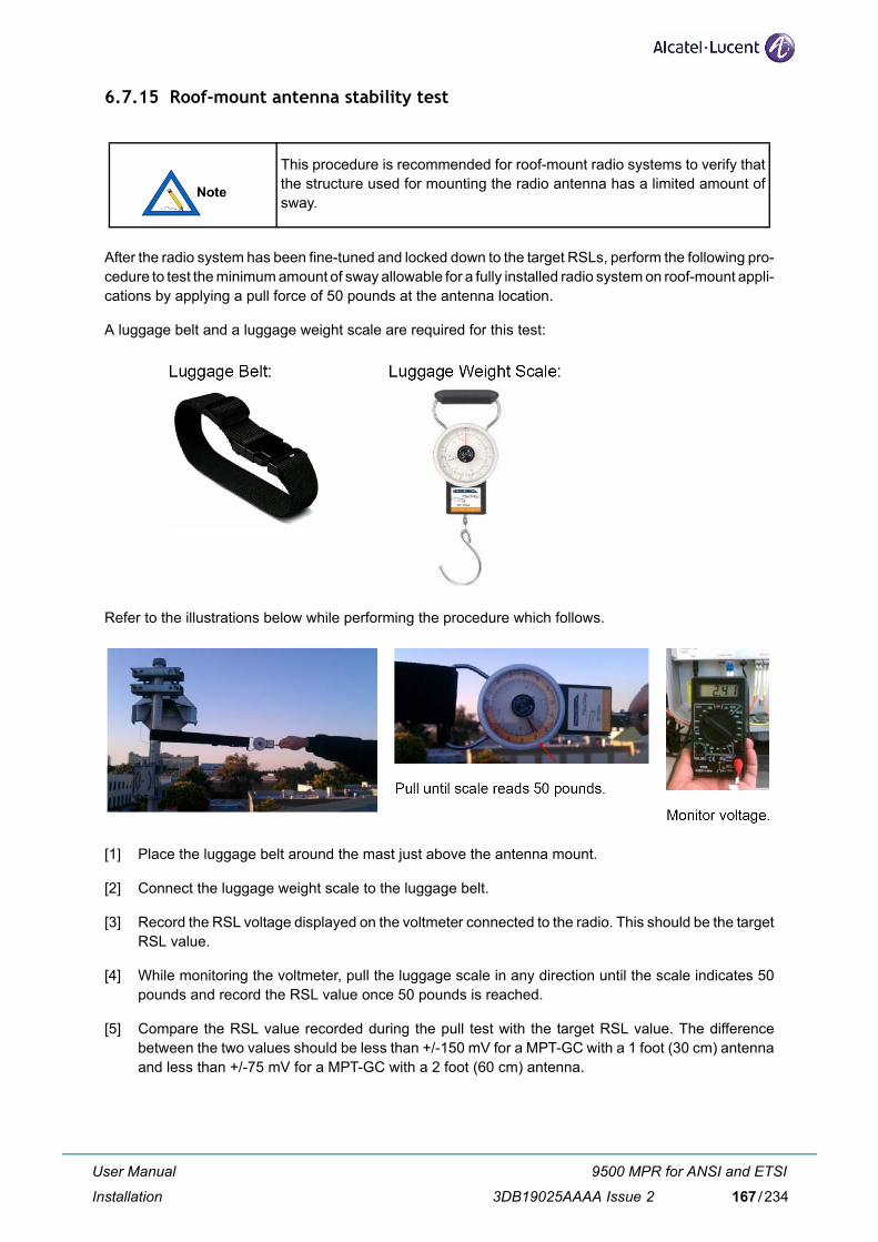
6.7.15 Roof-mount antenna stability test
After the radio system has been fine-tuned and locked down to the target RSLs, perform the following pro-cedure to test the minimum amount of sway allowable for a fully installed radio system on roof-mount appli-cations by applying a pull force of 50 pounds at the antenna location.
A luggage belt and a luggage weight scale are required for this test:
Refer to the illustrations below while performing the procedure which follows.
[1] Place the luggage belt around the mast just above the antenna mount.
[2] Connect the luggage weight scale to the luggage belt.
[3] Record the RSL voltage displayed on the voltmeter connected to the radio. This should be the targetRSL value.
[4] While monitoring the voltmeter, pull the luggage scale in any direction until the scale indicates 50pounds and record the RSL value once 50 pounds is reached.
[5] Compare the RSL value recorded during the pull test with the target RSL value. The differencebetween the two values should be less than +/-150 mV for a MPT-GC with a 1 foot (30 cm) antennaand less than +/-75 mV for a MPT-GC with a 2 foot (60 cm) antenna.
This procedure is recommended for roof-mount radio systems to verify thatthe structure used for mounting the radio antenna has a limited amount ofsway.
User Manual
Installation
9500 MPR for ANSI and ETSI
3DB19025AAAA Issue 2 167/234
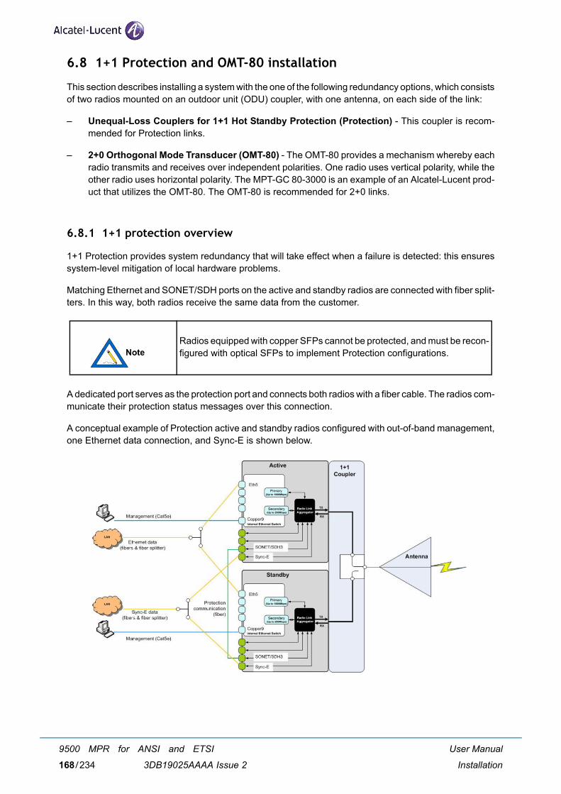
6.8 1+1 Protection and OMT-80 installation
This section describes installing a system with the one of the following redundancy options, which consistsof two radios mounted on an outdoor unit (ODU) coupler, with one antenna, on each side of the link:
– Unequal-Loss Couplers for 1+1 Hot Standby Protection (Protection) - This coupler is recom-mended for Protection links.
– 2+0 Orthogonal Mode Transducer (OMT-80) - The OMT-80 provides a mechanism whereby eachradio transmits and receives over independent polarities. One radio uses vertical polarity, while theother radio uses horizontal polarity. The MPT-GC 80-3000 is an example of an Alcatel-Lucent prod-uct that utilizes the OMT-80. The OMT-80 is recommended for 2+0 links.
6.8.1 1+1 protection overview
1+1 Protection provides system redundancy that will take effect when a failure is detected: this ensuressystem-level mitigation of local hardware problems.
Matching Ethernet and SONET/SDH ports on the active and standby radios are connected with fiber split-ters. In this way, both radios receive the same data from the customer.
A dedicated port serves as the protection port and connects both radios with a fiber cable. The radios com-municate their protection status messages over this connection.
A conceptual example of Protection active and standby radios configured with out-of-band management,one Ethernet data connection, and Sync-E is shown below.
Radios equipped with copper SFPs cannot be protected, and must be recon-figured with optical SFPs to implement Protection configurations.
User Manual
Installation
9500 MPR for ANSI and ETSI
3DB19025AAAA Issue 2168/234
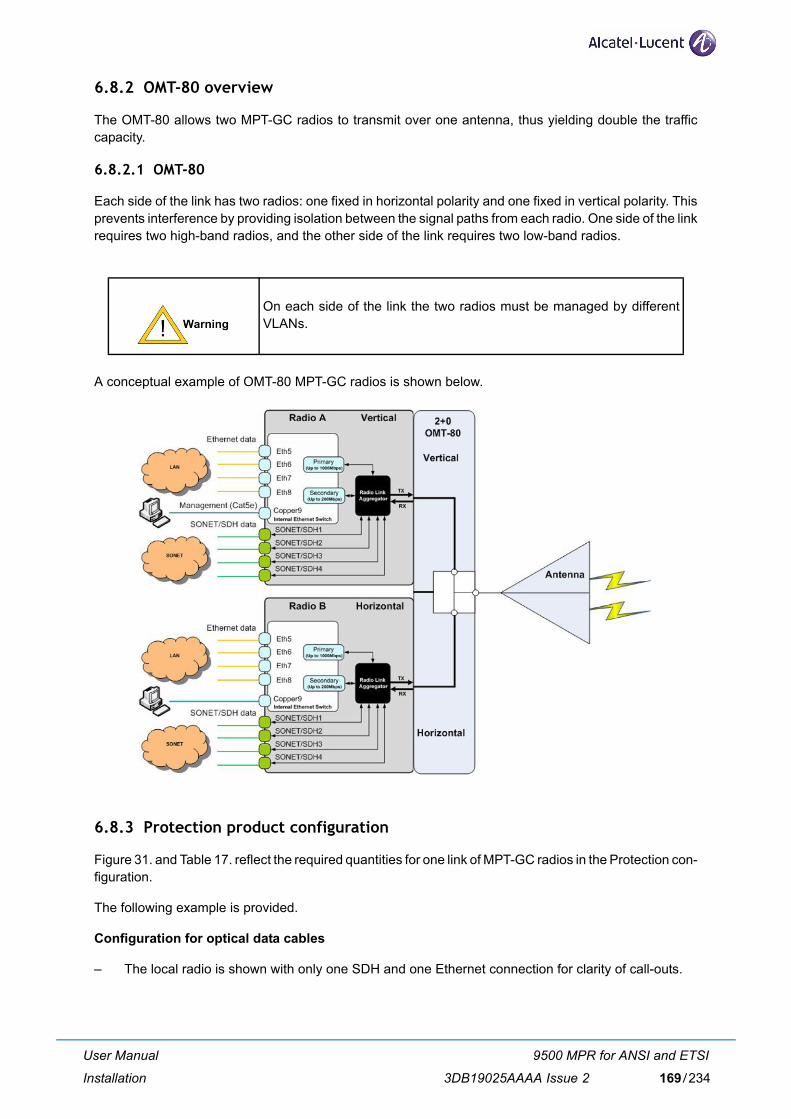
6.8.2 OMT-80 overview
The OMT-80 allows two MPT-GC radios to transmit over one antenna, thus yielding double the trafficcapacity.
6.8.2.1 OMT-80
Each side of the link has two radios: one fixed in horizontal polarity and one fixed in vertical polarity. Thisprevents interference by providing isolation between the signal paths from each radio. One side of the linkrequires two high-band radios, and the other side of the link requires two low-band radios.
A conceptual example of OMT-80 MPT-GC radios is shown below.
6.8.3 Protection product configuration
Figure 31. and Table 17. reflect the required quantities for one link of MPT-GC radios in the Protection con-figuration.
The following example is provided.
Configuration for optical data cables
– The local radio is shown with only one SDH and one Ethernet connection for clarity of call-outs.
On each side of the link the two radios must be managed by differentVLANs.
User Manual
Installation
9500 MPR for ANSI and ETSI
3DB19025AAAA Issue 2 169/234
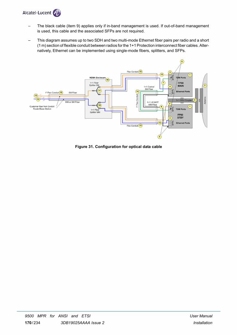
– The black cable (item 9) applies only if in-band management is used. If out-of-band managementis used, this cable and the associated SFPs are not required.
– This diagram assumes up to two SDH and two multi-mode Ethernet fiber pairs per radio and a short(1 m) section of flexible conduit between radios for the 1+1 Protection interconnect fiber cables. Alter-natively, Ethernet can be implemented using single-mode fibers, splitters, and SFPs.
Figure 31. Configuration for optical data cable
User Manual
Installation
9500 MPR for ANSI and ETSI
3DB19025AAAA Issue 2170/234
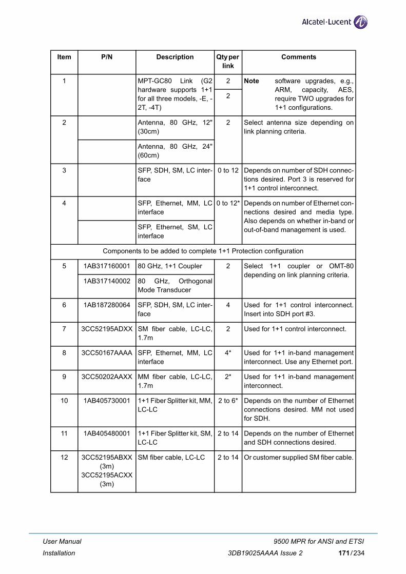
Item P/N Description Qty per link
Comments
1 MPT-GC80 Link (G2hardware supports 1+1for all three models, -E, -2T, -4T)
2 Note software upgrades, e.g.,ARM, capacity, AES,require TWO upgrades for1+1 configurations.
2
2 Antenna, 80 GHz, 12"(30cm)
2 Select antenna size depending onlink planning criteria.
Antenna, 80 GHz, 24"(60cm)
3 SFP, SDH, SM, LC inter-face
0 to 12 Depends on number of SDH connec-tions desired. Port 3 is reserved for1+1 control interconnect.
4 SFP, Ethernet, MM, LCinterface
0 to 12* Depends on number of Ethernet con-nections desired and media type.Also depends on whether in-band orout-of-band management is used.SFP, Ethernet, SM, LC
interface
Components to be added to complete 1+1 Protection configuration
5 1AB317160001 80 GHz, 1+1 Coupler 2 Select 1+1 coupler or OMT-80depending on link planning criteria.
1AB317140002 80 GHz, OrthogonalMode Transducer
6 1AB187280064 SFP, SDH, SM, LC inter-face
4 Used for 1+1 control interconnect.Insert into SDH port #3.
7 3CC52195ADXX SM fiber cable, LC-LC,1.7m
2 Used for 1+1 control interconnect.
8 3CC50167AAAA SFP, Ethernet, MM, LCinterface
4* Used for 1+1 in-band managementinterconnect. Use any Ethernet port.
9 3CC50202AAXX MM fiber cable, LC-LC,1.7m
2* Used for 1+1 in-band managementinterconnect.
10 1AB405730001 1+1 Fiber Splitter kit, MM,LC-LC
2 to 6* Depends on the number of Ethernetconnections desired. MM not usedfor SDH.
11 1AB405480001 1+1 Fiber Splitter kit, SM,LC-LC
2 to 14 Depends on the number of Ethernetand SDH connections desired.
12 3CC52195ABXX(3m)
3CC52195ACXX(3m)
SM fiber cable, LC-LC 2 to 14 Or customer supplied SM fiber cable.
User Manual
Installation
9500 MPR for ANSI and ETSI
3DB19025AAAA Issue 2 171/234
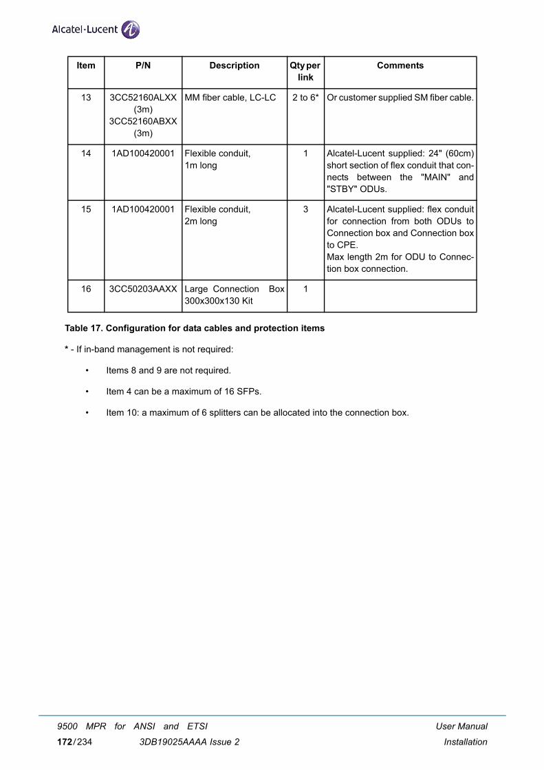
Table 17. Configuration for data cables and protection items
* - If in-band management is not required:
• Items 8 and 9 are not required.
• Item 4 can be a maximum of 16 SFPs.
• Item 10: a maximum of 6 splitters can be allocated into the connection box.
13 3CC52160ALXX(3m)
3CC52160ABXX(3m)
MM fiber cable, LC-LC 2 to 6* Or customer supplied SM fiber cable.
14 1AD100420001 Flexible conduit, 1m long
1 Alcatel-Lucent supplied: 24" (60cm)short section of flex conduit that con-nects between the "MAIN" and"STBY" ODUs.
15 1AD100420001 Flexible conduit, 2m long
3 Alcatel-Lucent supplied: flex conduitfor connection from both ODUs toConnection box and Connection boxto CPE.Max length 2m for ODU to Connec-tion box connection.
16 3CC50203AAXX Large Connection Box300x300x130 Kit
1
Item P/N Description Qty per link
Comments
User Manual
Installation
9500 MPR for ANSI and ETSI
3DB19025AAAA Issue 2172/234
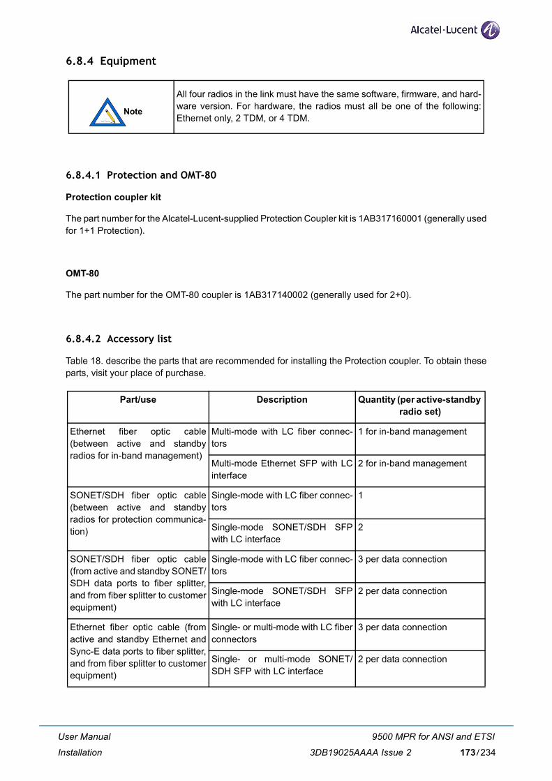
6.8.4 Equipment
6.8.4.1 Protection and OMT-80
Protection coupler kit
The part number for the Alcatel-Lucent-supplied Protection Coupler kit is 1AB317160001 (generally usedfor 1+1 Protection).
OMT-80
The part number for the OMT-80 coupler is 1AB317140002 (generally used for 2+0).
6.8.4.2 Accessory list
Table 18. describe the parts that are recommended for installing the Protection coupler. To obtain theseparts, visit your place of purchase.
All four radios in the link must have the same software, firmware, and hard-ware version. For hardware, the radios must all be one of the following:Ethernet only, 2 TDM, or 4 TDM.
Part/use Description Quantity (per active-standby radio set)
Ethernet fiber optic cable(between active and standbyradios for in-band management)
Multi-mode with LC fiber connec-tors
1 for in-band management
Multi-mode Ethernet SFP with LCinterface
2 for in-band management
SONET/SDH fiber optic cable(between active and standbyradios for protection communica-tion)
Single-mode with LC fiber connec-tors
1
Single-mode SONET/SDH SFPwith LC interface
2
SONET/SDH fiber optic cable(from active and standby SONET/SDH data ports to fiber splitter,and from fiber splitter to customerequipment)
Single-mode with LC fiber connec-tors
3 per data connection
Single-mode SONET/SDH SFPwith LC interface
2 per data connection
Ethernet fiber optic cable (fromactive and standby Ethernet andSync-E data ports to fiber splitter,and from fiber splitter to customerequipment)
Single- or multi-mode with LC fiberconnectors
3 per data connection
Single- or multi-mode SONET/SDH SFP with LC interface
2 per data connection
User Manual
Installation
9500 MPR for ANSI and ETSI
3DB19025AAAA Issue 2 173/234
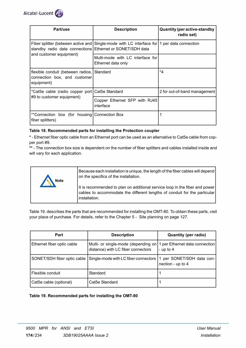
Table 18. Recommended parts for installing the Protection coupler* - Ethernet fiber optic cable from an Ethernet port can be used as an alternative to Cat5e cable from cop-per port #9.** - The connection box size is dependent on the number of fiber splitters and cables installed inside andwill vary for each application.
Table 19. describes the parts that are recommended for installing the OMT-80. To obtain these parts, visityour place of purchase. For details, refer to the Chapter 5 - Site planning on page 127.
Table 19. Recommended parts for installing the OMT-80
Fiber splitter (between active andstandby radio data connectionsand customer equipment)
Single-mode with LC interface forEthernet or SONET/SDH data
1 per data connection
Multi-mode with LC interface forEthernet data only
flexible conduit (between radios,connection box, and customerequipment)
Standard *4
*Cat5e cable (radio copper port#9 to customer equipment)
Cat5e Standard 2 for out-of-band management
Copper Ethernet SFP with RJ45interface
**Connection box (for housingfiber splitters)
Connection Box 1
Because each installation is unique, the length of the fiber cables will dependon the specifics of the installation.
It is recommended to plan on additional service loop in the fiber and powercables to accommodate the different lengths of conduit for the particularinstallation.
Part Description Quantity (per radio)
Ethernet fiber optic cable Multi- or single-mode (depending ondistance) with LC fiber connectors
1 per Ethernet data connection- up to 4
SONET/SDH fiber optic cable Single-mode with LC fiber connectors 1 per SONET/SDH data con-nection - up to 4
Flexible conduit Standard 1
Cat5e cable (optional) Cat5e Standard 1
Part/use Description Quantity (per active-standby radio set)
User Manual
Installation
9500 MPR for ANSI and ETSI
3DB19025AAAA Issue 2174/234
6.8.4.3
6.8.4.4 Installation tools
The following tools are required for installing the radio and the antenna:
– Screwdriver, slotted 0.1 inch wide.
– Open-end wrench 9/16 inch - q.ty 2 (Alcatel-Lucent supplied).
– Open-end wrench 1/2 inch.
– Ratchet with 6 inch extension and 9/16 inch deep socket.
– Wire stripper/cutter/crimp tool (10-16 gauge).
– Electrical tape.
– Fish tape (draw wire) for pulling cable.
– Cable tie wraps.
– Hand-held digital voltmeter (DVM) with standard banana-plug receptacles.
– Allen wrench 3/16 inch - q.ty 2 (Alcatel-Lucent supplied).
User Manual
Installation
9500 MPR for ANSI and ETSI
3DB19025AAAA Issue 2 175/234
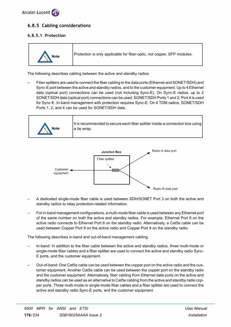
6.8.5 Cabling considerations
6.8.5.1 Protection
The following describes cabling between the active and standby radios.
– Fiber splitters are used to connect the fiber cabling to the data ports (Ethernet and SONET/SDH) andSync-E port between the active and standby radios, and to the customer equipment. Up to 4 Ethernetdata (optical port) connections can be used (not including Sync-E). On Sync-E radios, up to 2SONET/SDH data (optical port) connections can be used: SONET/SDH Ports 1 and 2; Port 4 is usedfor Sync-E. In-band management with protection requires Sync-E. On 4 TDM radios, SONET/SDHPorts 1, 2, and 4 can be used for SONET/SDH data.
– A dedicated single-mode fiber cable is used between SDH/SONET Port 3 on both the active andstandby radios to relay protection-related information.
– For in-band management configurations, a multi-mode fiber cable is used between any Ethernet portof the same number on both the active and standby radios. For example, Ethernet Port 8 on theactive radio connects to Ethernet Port 8 on the standby radio. Alternatively, a Cat5e cable can beused between Copper Port 9 on the active radio and Copper Port 9 on the standby radio.
The following describes in-band and out-of-band management cabling.
– In-band: In addition to the fiber cable between the active and standby radios, three multi-mode orsingle-mode fiber cables and a fiber splitter are used to connect the active and standby radio Sync-E ports, and the customer equipment.
– Out-of-band: One Cat5e cable can be used between the copper port on the active radio and the cus-tomer equipment. Another Cat5e cable can be used between the copper port on the standby radioand the customer equipment. Alternatively, fiber cabling from Ethernet data ports on the active andstandby radios can be used as an alternative to Cat5e cabling from the active and standby radio cop-per ports. Three multi-mode or single-mode fiber cables and a fiber splitter are used to connect theactive and standby radio Sync-E ports, and the customer equipment.
Protection is only applicable for fiber-optic, not copper, SFP modules.
It is recommended to secure each fiber splitter inside a connection box usinga tie wrap.
User Manual
Installation
9500 MPR for ANSI and ETSI
3DB19025AAAA Issue 2176/234
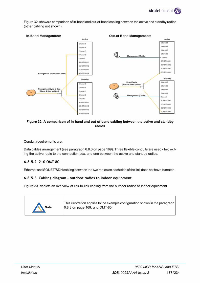
Figure 32. shows a comparison of in-band and out-of-band cabling between the active and standby radios(other cabling not shown).
Figure 32. A comparison of in-band and out-of-band cabling between the active and standby radios
Conduit requirements are:
Data cables arrangement (see paragraph 6.8.3 on page 169): Three flexible conduits are used - two exit-ing the active radio to the connection box, and one between the active and standby radios.
6.8.5.2 2+0 OMT-80
Ethernet and SONET/SDH cabling between the two radios on each side of the link does not have to match.
6.8.5.3 Cabling diagram - outdoor radios to indoor equipment
Figure 33. depicts an overview of link-to-link cabling from the outdoor radios to indoor equipment.
This illustration applies to the example configuration shown in the paragraph6.8.3 on page 169, and OMT-80.
User Manual
Installation
9500 MPR for ANSI and ETSI
3DB19025AAAA Issue 2 177/234
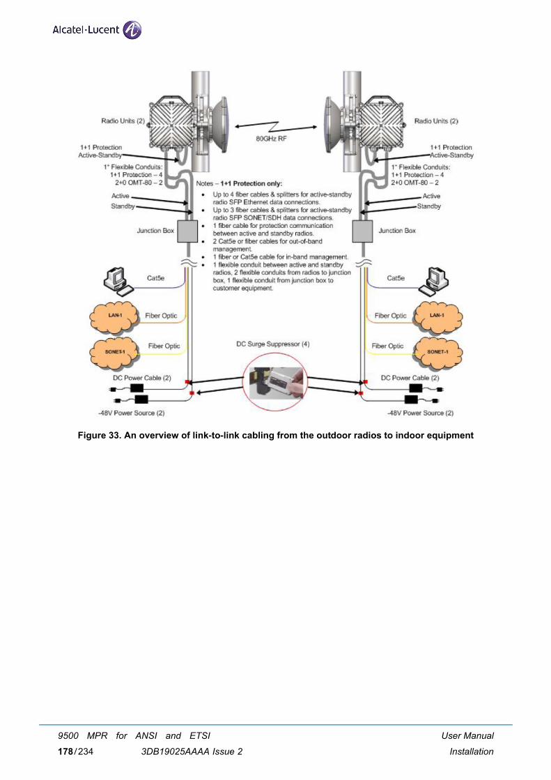
Figure 33. An overview of link-to-link cabling from the outdoor radios to indoor equipment
User Manual
Installation
9500 MPR for ANSI and ETSI
3DB19025AAAA Issue 2178/234
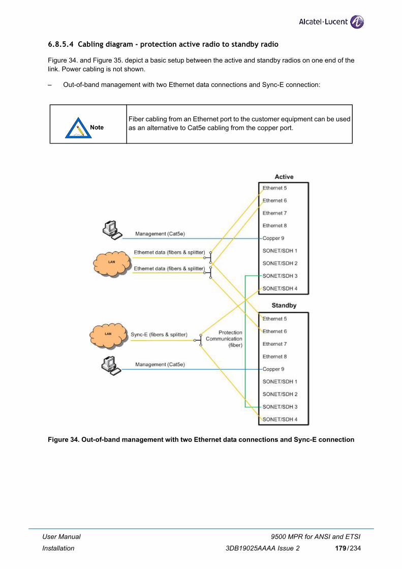
6.8.5.4 Cabling diagram - protection active radio to standby radio
Figure 34. and Figure 35. depict a basic setup between the active and standby radios on one end of thelink. Power cabling is not shown.
– Out-of-band management with two Ethernet data connections and Sync-E connection:
Figure 34. Out-of-band management with two Ethernet data connections and Sync-E connection
Fiber cabling from an Ethernet port to the customer equipment can be usedas an alternative to Cat5e cabling from the copper port.
User Manual
Installation
9500 MPR for ANSI and ETSI
3DB19025AAAA Issue 2 179/234
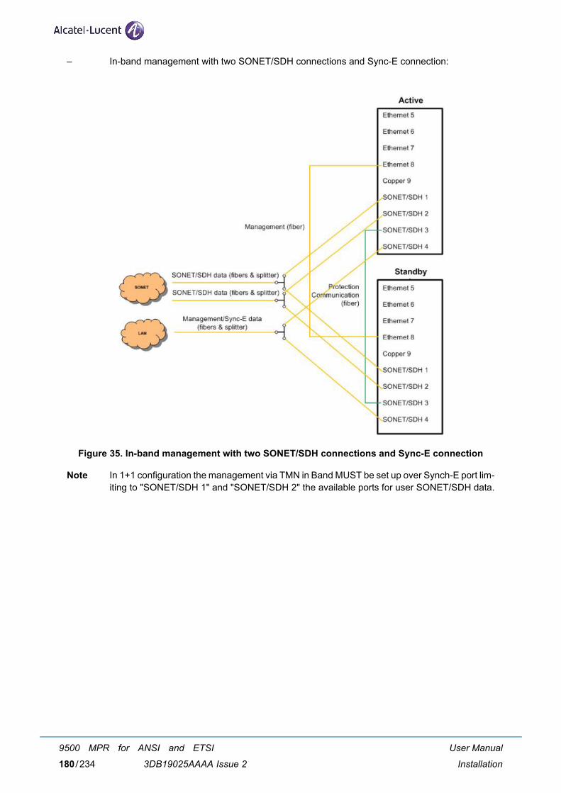
– In-band management with two SONET/SDH connections and Sync-E connection:
Figure 35. In-band management with two SONET/SDH connections and Sync-E connection
Note In 1+1 configuration the management via TMN in Band MUST be set up over Synch-E port lim-iting to "SONET/SDH 1" and "SONET/SDH 2" the available ports for user SONET/SDH data.
User Manual
Installation
9500 MPR for ANSI and ETSI
3DB19025AAAA Issue 2180/234
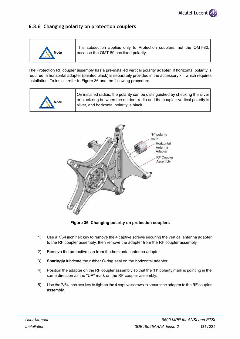
6.8.6 Changing polarity on protection couplers
The Protection RF coupler assembly has a pre-installed vertical polarity adapter. If horizontal polarity isrequired, a horizontal adapter (painted black) is separately provided in the accessory kit, which requiresinstallation. To install, refer to Figure 36.and the following procedure.
Figure 36. Changing polarity on protection couplers
1) Use a 7/64 inch hex key to remove the 4 captive screws securing the vertical antenna adapterto the RF coupler assembly, then remove the adapter from the RF coupler assembly.
2) Remove the protective cap from the horizontal antenna adapter.
3) Sparingly lubricate the rubber O-ring seal on the horizontal adapter.
4) Position the adapter on the RF coupler assembly so that the "H" polarity mark is pointing in thesame direction as the "UP" mark on the RF coupler assembly.
5) Use the 7/64 inch hex key to tighten the 4 captive screws to secure the adapter to the RF couplerassembly.
This subsection applies only to Protection couplers, not the OMT-80,because the OMT-80 has fixed polarity.
On installed radios, the polarity can be distinguished by checking the silveror black ring between the outdoor radio and the coupler: vertical polarity issilver, and horizontal polarity is black.
User Manual
Installation
9500 MPR for ANSI and ETSI
3DB19025AAAA Issue 2 181/234

6.8.7 Antenna mount installation
Install the antenna to the mast as summarized in Figure 37. and the procedure below. For details, referto the paragraph 6.7.1 - Phase 1: Antenna mount installation on page 147.
Figure 37. Antenna mount installation
1) Attach the upper pole mount to the antenna mounting plate.
2) Attach the lower pole mount to the opposite side of the plate, and azimuth fine adjust.
3) Install the shoulder screw.
4) Attach the pole mount assembly to the antenna.
5) Mount the antenna to the mast.
6) Remove the protective plastic cap from the antenna port.
User Manual
Installation
9500 MPR for ANSI and ETSI
3DB19025AAAA Issue 2182/234

6.8.8 RF Coupler assembly and radio installation
The following describes the recommended sequence, in which the RF coupler assembly is attached tothe antenna mounting assembly, and then one radio at a time is attached to the RF coupler assembly.
To install the RF coupler assembly and radios, refer to Figure 38. and the following procedure. (The Pro-tection option is shown below, but the installation sequence is the same for the Protection coupler andOMT-80, except where noted.)
Figure 38. RF Coupler assembly and radio installation
1) Remove the protective cap from the antenna adapter (on the RF coupler assembly).
2) Position the RF coupler assembly against the antenna mounting assembly so that the "UP"mark points up.
3) Tighten the four captive bolts in a star pattern to secure the RF coupler assembly to the antennamounting assembly. On the OMT-80, these bolts will also be used to fine-tune the polarizationskew.
The local end of the link should have two high-band radios, and the remoteend should have two low-band radios - do not put high- and low-band radiosat the same end of the link.
For the OMT-80, use a level while tightening the bolts to ensure the coupleris vertically level.
User Manual
Installation
9500 MPR for ANSI and ETSI
3DB19025AAAA Issue 2 183/234
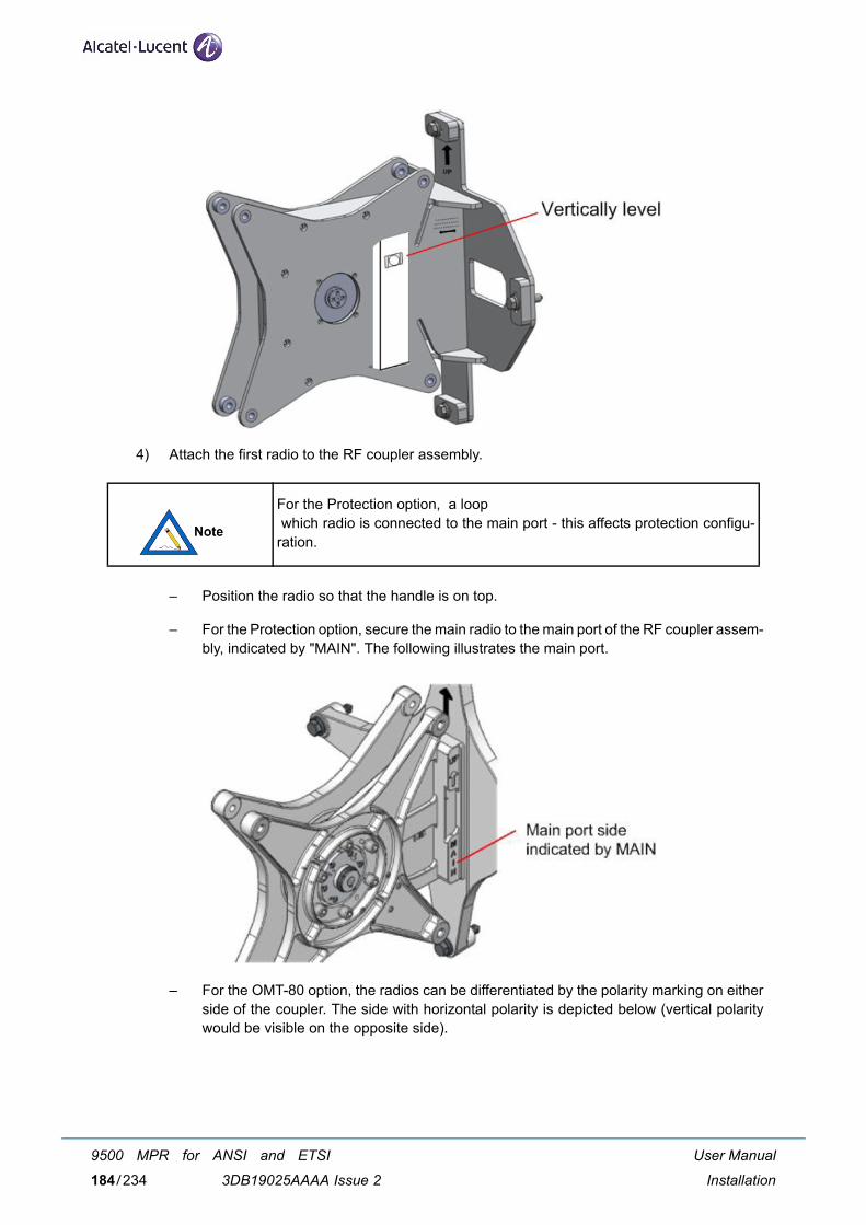
4) Attach the first radio to the RF coupler assembly.
– Position the radio so that the handle is on top.
– For the Protection option, secure the main radio to the main port of the RF coupler assem-bly, indicated by "MAIN". The following illustrates the main port.
– For the OMT-80 option, the radios can be differentiated by the polarity marking on eitherside of the coupler. The side with horizontal polarity is depicted below (vertical polaritywould be visible on the opposite side).
For the Protection option, a loop which radio is connected to the main port - this affects protection configu-ration.
User Manual
Installation
9500 MPR for ANSI and ETSI
3DB19025AAAA Issue 2184/234
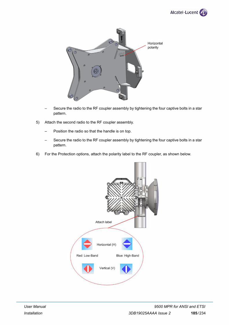
– Secure the radio to the RF coupler assembly by tightening the four captive bolts in a starpattern.
5) Attach the second radio to the RF coupler assembly.
– Position the radio so that the handle is on top.
– Secure the radio to the RF coupler assembly by tightening the four captive bolts in a starpattern.
6) For the Protection options, attach the polarity label to the RF coupler, as shown below.
User Manual
Installation
9500 MPR for ANSI and ETSI
3DB19025AAAA Issue 2 185/234

6.8.9 Antenna adjustment
Adjust the antenna as summarized below. For details, refer to the paragraph 6.7.2 - Phase 2: Antennaand MPT-GC installation on page 152.
1) Course align azimuth (side-to-side or horizontal) and tighten the 4 carriage bolts to secure thepole mounts.
2) Loosen the 4 azimuth lock bolts.
3) Adjust the eyebolt length, using a 9/16 inch open-end wrench, to the required location.
4) Secure the 4 azimuth lock bolts (tighten until the lock washers are flattened).
5) Loosen the 2 antenna mounting bolts.
6) Rotate the elevation fine-adjust hex nut as required to set the correct elevation (up-down or ver-tical).
7) Tighten the 2 antenna mounting bolts after the correct elevation is set.
User Manual
Installation
9500 MPR for ANSI and ETSI
3DB19025AAAA Issue 2186/234
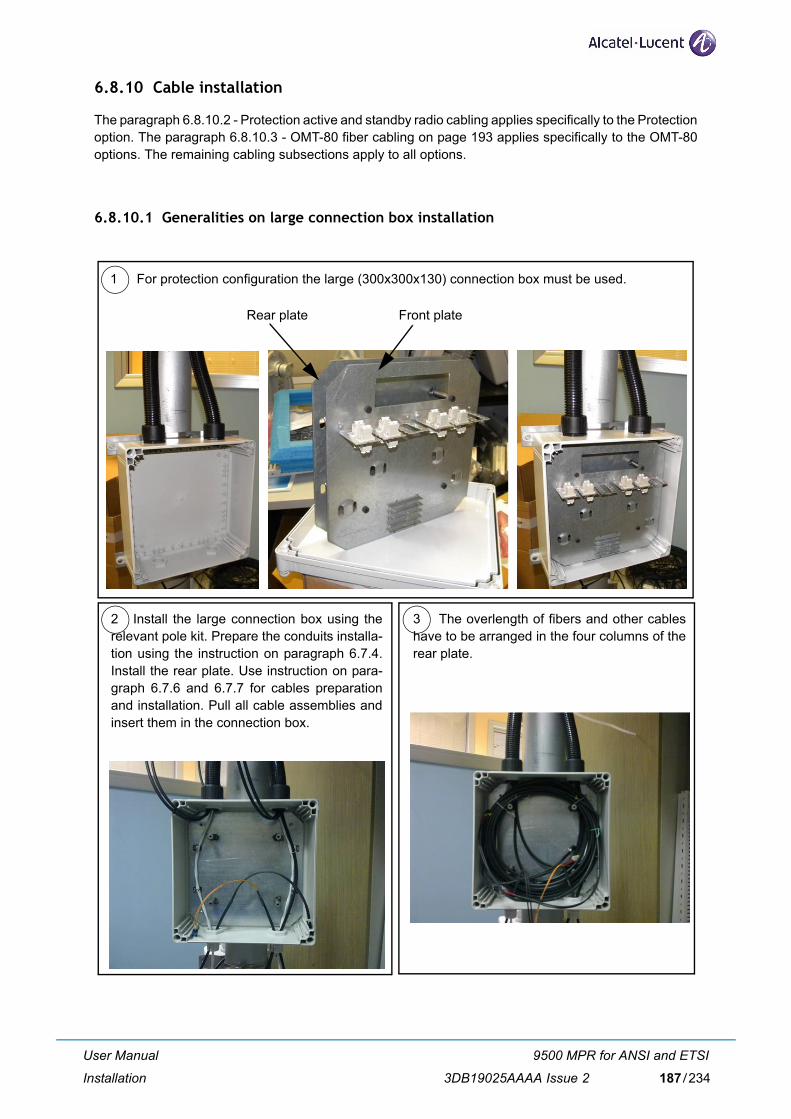
6.8.10 Cable installation
The paragraph 6.8.10.2 - Protection active and standby radio cabling applies specifically to the Protectionoption. The paragraph 6.8.10.3 - OMT-80 fiber cabling on page 193 applies specifically to the OMT-80options. The remaining cabling subsections apply to all options.
6.8.10.1 Generalities on large connection box installation
2 Install the large connection box using therelevant pole kit. Prepare the conduits installa-tion using the instruction on paragraph 6.7.4.Install the rear plate. Use instruction on para-graph 6.7.6 and 6.7.7 for cables preparationand installation. Pull all cable assemblies andinsert them in the connection box.
3 The overlength of fibers and other cableshave to be arranged in the four columns of therear plate.
1 For protection configuration the large (300x300x130) connection box must be used.
Front plateRear plate
User Manual
Installation
9500 MPR for ANSI and ETSI
3DB19025AAAA Issue 2 187/234
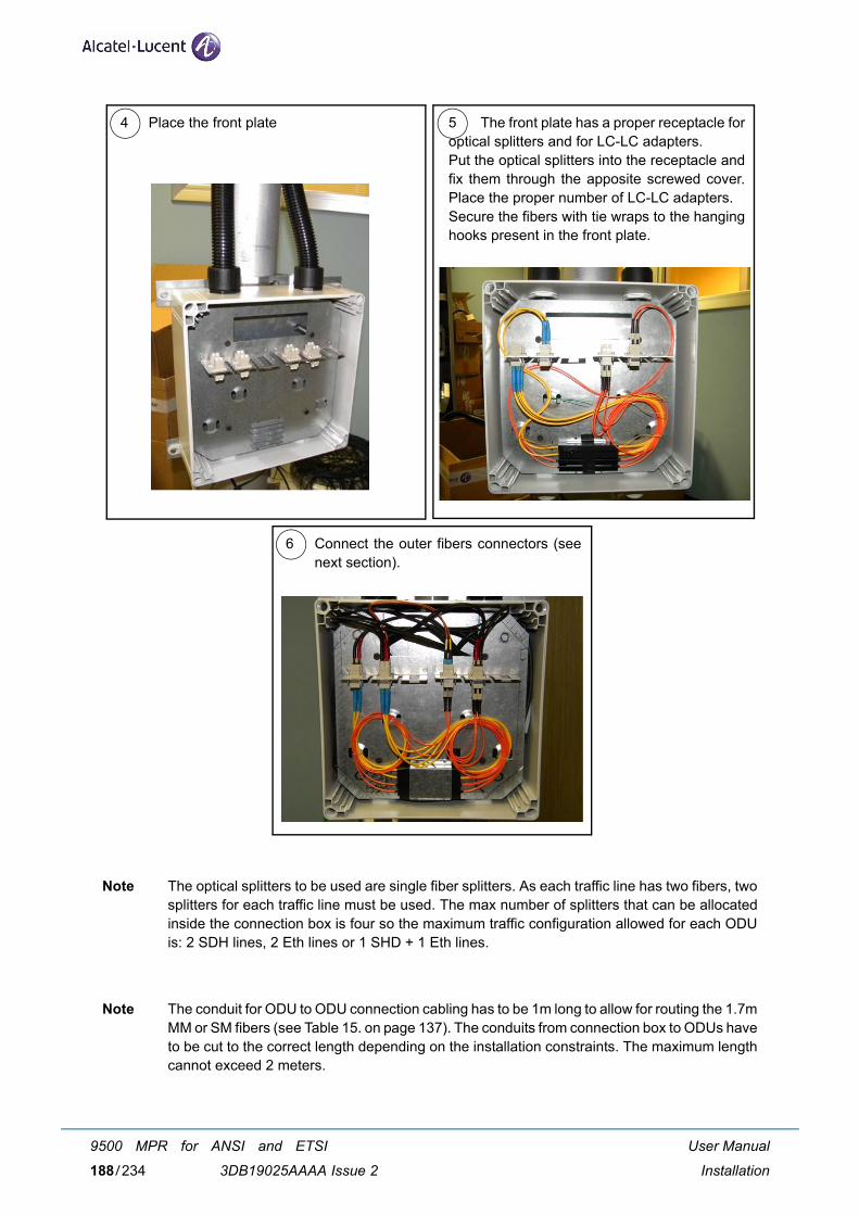
Note The optical splitters to be used are single fiber splitters. As each traffic line has two fibers, twosplitters for each traffic line must be used. The max number of splitters that can be allocatedinside the connection box is four so the maximum traffic configuration allowed for each ODUis: 2 SDH lines, 2 Eth lines or 1 SHD + 1 Eth lines.
Note The conduit for ODU to ODU connection cabling has to be 1m long to allow for routing the 1.7mMM or SM fibers (see Table 15. on page 137). The conduits from connection box to ODUs haveto be cut to the correct length depending on the installation constraints. The maximum lengthcannot exceed 2 meters.
4 Place the front plate 5 The front plate has a proper receptacle foroptical splitters and for LC-LC adapters.Put the optical splitters into the receptacle andfix them through the apposite screwed cover.Place the proper number of LC-LC adapters. Secure the fibers with tie wraps to the hanginghooks present in the front plate.
6 Connect the outer fibers connectors (seenext section).
User Manual
Installation
9500 MPR for ANSI and ETSI
3DB19025AAAA Issue 2188/234
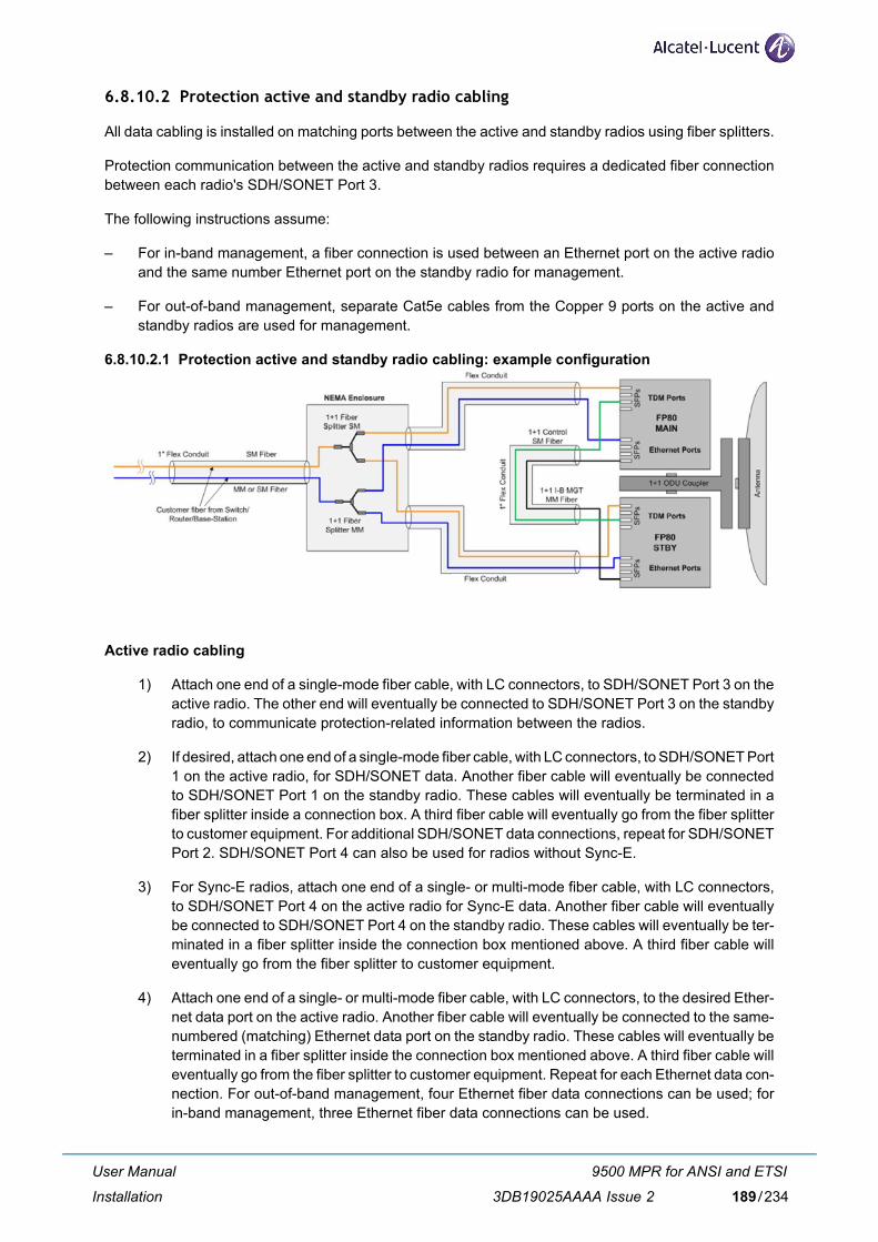
6.8.10.2 Protection active and standby radio cabling
All data cabling is installed on matching ports between the active and standby radios using fiber splitters.
Protection communication between the active and standby radios requires a dedicated fiber connectionbetween each radio's SDH/SONET Port 3.
The following instructions assume:
– For in-band management, a fiber connection is used between an Ethernet port on the active radioand the same number Ethernet port on the standby radio for management.
– For out-of-band management, separate Cat5e cables from the Copper 9 ports on the active andstandby radios are used for management.
6.8.10.2.1 Protection active and standby radio cabling: example configuration
Active radio cabling
1) Attach one end of a single-mode fiber cable, with LC connectors, to SDH/SONET Port 3 on theactive radio. The other end will eventually be connected to SDH/SONET Port 3 on the standbyradio, to communicate protection-related information between the radios.
2) If desired, attach one end of a single-mode fiber cable, with LC connectors, to SDH/SONET Port1 on the active radio, for SDH/SONET data. Another fiber cable will eventually be connectedto SDH/SONET Port 1 on the standby radio. These cables will eventually be terminated in afiber splitter inside a connection box. A third fiber cable will eventually go from the fiber splitterto customer equipment. For additional SDH/SONET data connections, repeat for SDH/SONETPort 2. SDH/SONET Port 4 can also be used for radios without Sync-E.
3) For Sync-E radios, attach one end of a single- or multi-mode fiber cable, with LC connectors,to SDH/SONET Port 4 on the active radio for Sync-E data. Another fiber cable will eventuallybe connected to SDH/SONET Port 4 on the standby radio. These cables will eventually be ter-minated in a fiber splitter inside the connection box mentioned above. A third fiber cable willeventually go from the fiber splitter to customer equipment.
4) Attach one end of a single- or multi-mode fiber cable, with LC connectors, to the desired Ether-net data port on the active radio. Another fiber cable will eventually be connected to the same-numbered (matching) Ethernet data port on the standby radio. These cables will eventually beterminated in a fiber splitter inside the connection box mentioned above. A third fiber cable willeventually go from the fiber splitter to customer equipment. Repeat for each Ethernet data con-nection. For out-of-band management, four Ethernet fiber data connections can be used; forin-band management, three Ethernet fiber data connections can be used.
User Manual
Installation
9500 MPR for ANSI and ETSI
3DB19025AAAA Issue 2 189/234

5) For in-band management, attach one end of a fiber cable to an Ethernet port on the active radio.The other end will eventually be connected to the same-numbered Ethernet port on the standbyradio.
For out-of-band management, attach one end of a Cat5e cable to the Copper Port 9 on theactive radio.
6) Route the fiber cables used for in-band management (if applicable) and protection communi-cation through the straight-through fitting, then attach the flexible conduit to the fitting, ensuringthat the cables do not get pinched when the conduit is pushed on to the fitting. Route thesecables, which will connect to the standby radio, through this conduit.
7) Install the power cabling on the active radio. Refer to the Power Cabling subsection.
8) Route the following cables through the other straight-through fitting: fiber cables for data andSync-E, Copper 9, and power. Then, attach the flexible conduit to the fitting. Route thesecables, which will connect to the connection box, through this conduit.
Standby radio cabling
1) Attach the end of the cable from SDH/SONET Port 3 on the active radio to SDH/SONET Port3 on the standby radio (protection communication).
2) If using SDH/SONET Ports 1, 2, or 4 for data, attach one end of a single-mode fiber cable withLC connectors, for each applicable SONET/SDH port, on the standby radio. These connec-tion(s) should match the SDH/SONET port(s) used on the active radio. These cables will even-tually be terminated in a fiber splitter inside the connection box.
3) For Sync-E radios, attach one end of a multi-mode fiber cable with LC connectors, to SDH/SONET Port 4 on the standby radio for Sync-E data. This cable will eventually be terminatedin a fiber splitter inside the connection box.
4) Attach one end of a single- or multi-mode fiber cable with LC connectors, for each applicableEthernet port, on the standby radio. These connection(s) must match the Ethernet port(s) usedon the active radio. These cables will eventually be terminated in a fiber splitter inside the con-nection box.
5) For in-band management, attach the end of the cable from the Ethernet port on the active radiodedicated for in-band management to the matching Ethernet port on the standby radio.
For out-of-band management, attach one end of a Cat5e cable to Copper Port 9 on the standbyradio.
6) Install the power cabling on the standby radio. Refer to the Power Cabling subsection.
7) Attach the flexible conduit from the active radio to a conduit fitting on the standby radio, toenclose the cabling between the active and standby radios (in-band management, if applicable,and protection communication).
8) Route the following cables through the other straight-through fitting on the standby radio: fibercables for data and Sync-E, Copper 9, and power. Then attach the flexible conduit to the fitting.Route these cables, which will connect to the connection box, through this conduit.
Connection box cabling
1) Prepare and install the large connection box as in paragraph 6.8.10.1 on page 187.
User Manual
Installation
9500 MPR for ANSI and ETSI
3DB19025AAAA Issue 2190/234

2) For each data and Sync-E connection: a) Route the fiber cable from the active radio throughone entry of the connection box and attach the fiber cable LC connector to one sleeve of a fibersplitter. b) Route the fiber cable from the standby radio matching port through the other entryof the connection box and attach the fiber cable LC connector to the second sleeve of the fibersplitter. c) Attach a third fiber cable with an LC connector to the third sleeve of the fiber splitterto eventually be routed from the connection box exit to customer equipment.
Use one multi-mode fiber splitter per matching Ethernet or Sync-E port, and one single-modefiber splitter per matching SONET/SDH port.
3) For out-of-band management, a) Route the cable from the active radio Copper 9 port throughthe connection box entry designated for the active radio. b) Route the cable from the standbyradio Copper 9 port through the connection box entry designated for the standby radio.
4) Route the power cable from the active radio through the connection box entry designated forthe active radio; route the power cable from the active radio through the connection box entrydesignated for the standby radio.
5) Attach flexible conduit to both connection box entries.
6) Route the following cables through the connection box exit: data and Sync-E fiber cables fromthe third sleeve of the fiber splitters, Copper 9 port, and power.
7) Attach flexible conduit to the connection box exit.
8) Connect the fiber and Cat5e cables at the customer equipment.
It is recommended to secure the fiber splitters inside the connection boxusing a tie wrap.
User Manual
Installation
9500 MPR for ANSI and ETSI
3DB19025AAAA Issue 2 191/234
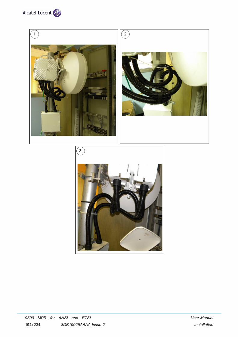
1 2
3
User Manual
Installation
9500 MPR for ANSI and ETSI
3DB19025AAAA Issue 2192/234
6.8.10.3 OMT-80 fiber cabling
1) Install the desired SFP modules in the radio with duplex MMF or SMF fiber from the radio tothe network termination equipment (switch or router with 1000Base-X port or SONET/SDHequipment). The cable should be looped around the inside of the enclosure to provide strain-relief. The connectors on the radio end of the fiber require a duplex LC connector; the connec-tors on the switch/router end should mate to the network equipment.
2) Connect the fibers at the network equipment.
6.8.10.4 Power cabling
Please refer to the Power Cabling subsection.
6.8.10.5 Ground cabling
The preferred method for grounding the radio is to ground the mast to a ground source. If this is not pos-sible, perform the following:
1) Insert the ground cable into the grounding hole of the radio and tighten the 9/16 inch groundingbolt to hold the ground cable.
2) Connect the other end of the ground cable to a nearby ground location.
6.8.10.6 10/100/1000 Base-T surge suppressor
It is recommended to use a surge suppressor at the point where the cable enters a building or is connectedto other outdoor equipment that does not already contain surge suppression hardware.
6.8.10.7 RSL test cable
Please refer to the RSL Test Cable subsection.
The following summarizes surge suppressor cabling. For details, refer to the10/100/1000 Base-T Surge Suppressor subsection.
When removing the cover of the radio to measure voltage, open the claspnearest the antenna last. When replacing the cover, close the clasp nearestthe antenna last.
User Manual
Installation
9500 MPR for ANSI and ETSI
3DB19025AAAA Issue 2 193/234
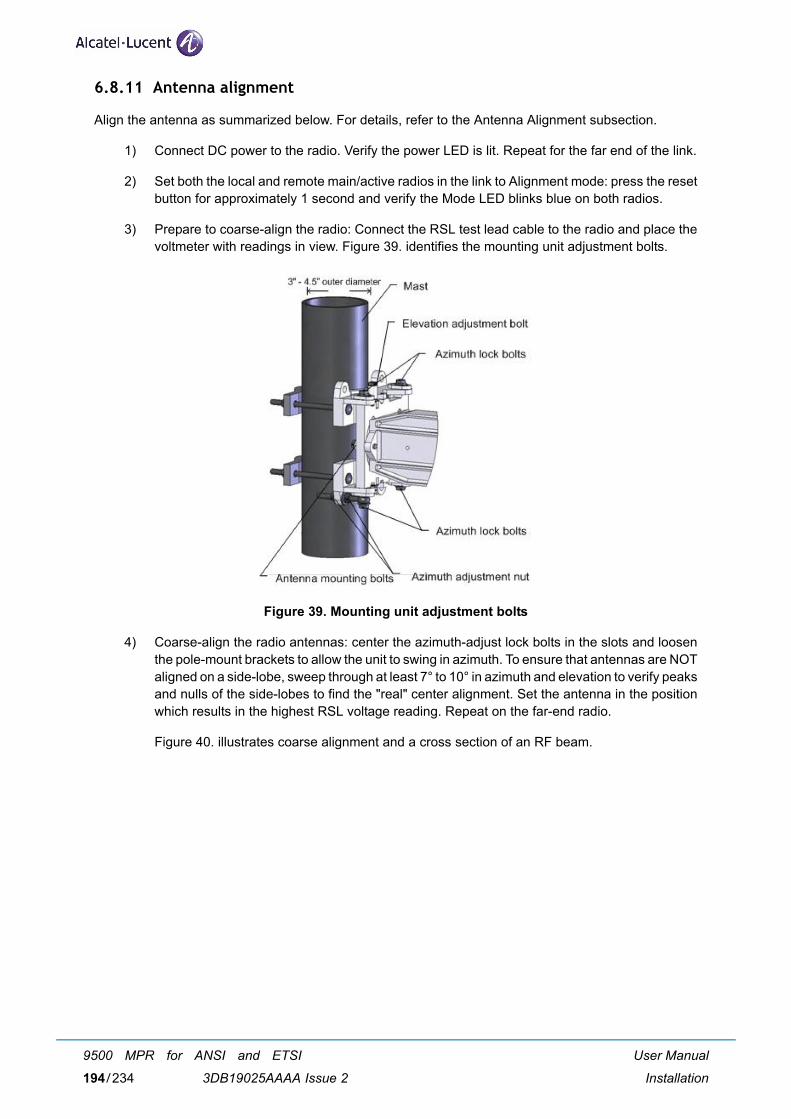
6.8.11 Antenna alignment
Align the antenna as summarized below. For details, refer to the Antenna Alignment subsection.
1) Connect DC power to the radio. Verify the power LED is lit. Repeat for the far end of the link.
2) Set both the local and remote main/active radios in the link to Alignment mode: press the resetbutton for approximately 1 second and verify the Mode LED blinks blue on both radios.
3) Prepare to coarse-align the radio: Connect the RSL test lead cable to the radio and place thevoltmeter with readings in view. Figure 39. identifies the mounting unit adjustment bolts.
Figure 39. Mounting unit adjustment bolts
4) Coarse-align the radio antennas: center the azimuth-adjust lock bolts in the slots and loosenthe pole-mount brackets to allow the unit to swing in azimuth. To ensure that antennas are NOTaligned on a side-lobe, sweep through at least 7° to 10° in azimuth and elevation to verify peaksand nulls of the side-lobes to find the "real" center alignment. Set the antenna in the positionwhich results in the highest RSL voltage reading. Repeat on the far-end radio.
Figure 40. illustrates coarse alignment and a cross section of an RF beam.
User Manual
Installation
9500 MPR for ANSI and ETSI
3DB19025AAAA Issue 2194/234
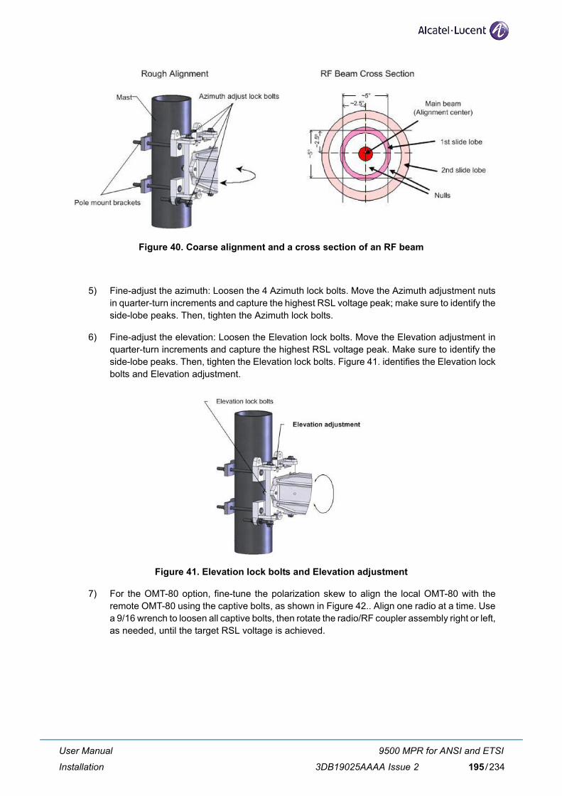
Figure 40. Coarse alignment and a cross section of an RF beam
5) Fine-adjust the azimuth: Loosen the 4 Azimuth lock bolts. Move the Azimuth adjustment nutsin quarter-turn increments and capture the highest RSL voltage peak; make sure to identify theside-lobe peaks. Then, tighten the Azimuth lock bolts.
6) Fine-adjust the elevation: Loosen the Elevation lock bolts. Move the Elevation adjustment inquarter-turn increments and capture the highest RSL voltage peak. Make sure to identify theside-lobe peaks. Then, tighten the Elevation lock bolts. Figure 41. identifies the Elevation lockbolts and Elevation adjustment.
Figure 41. Elevation lock bolts and Elevation adjustment
7) For the OMT-80 option, fine-tune the polarization skew to align the local OMT-80 with theremote OMT-80 using the captive bolts, as shown in Figure 42.. Align one radio at a time. Usea 9/16 wrench to loosen all captive bolts, then rotate the radio/RF coupler assembly right or left,as needed, until the target RSL voltage is achieved.
User Manual
Installation
9500 MPR for ANSI and ETSI
3DB19025AAAA Issue 2 195/234
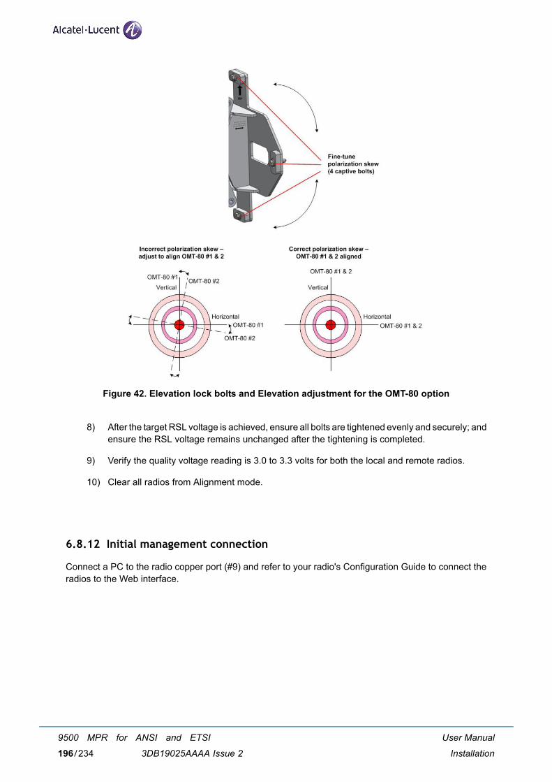
Figure 42. Elevation lock bolts and Elevation adjustment for the OMT-80 option
8) After the target RSL voltage is achieved, ensure all bolts are tightened evenly and securely; andensure the RSL voltage remains unchanged after the tightening is completed.
9) Verify the quality voltage reading is 3.0 to 3.3 volts for both the local and remote radios.
10) Clear all radios from Alignment mode.
6.8.12 Initial management connection
Connect a PC to the radio copper port (#9) and refer to your radio's Configuration Guide to connect theradios to the Web interface.
User Manual
Installation
9500 MPR for ANSI and ETSI
3DB19025AAAA Issue 2196/234
7 ProvisioningThis chapter describes the first installation procedures to configure the NE.
7.1 PC characteristics
The PC to be used for MPT-GC application must meet following characteristics:
PC Hardware Configuration:
– CPU: AMD Atlhon/Intel Celeron/Intel Pentium 4 or higher
– RAM: 1 GB
– Hard Disk space: 1.5 GB (available space for log files, JRE excluded)
– Display Resolution: 1280x800 pixel
– Ethernet Interface: Ethernet Card 10/100 Mbps
Operating Systems Supported:
– Microsoft Windows XP Professional service pack 3 or Microsoft Windows Vista Ultimate service pack2 or Windows 7
Additional requirements:
– Microsoft Internet Explorer 6 SP1, 7, 8, Mozilla Firefox 2, 3, 3.5.
User Manual
Provisioning
9500 MPR for ANSI and ETSI
3DB19025AAAA Issue 2 197/234
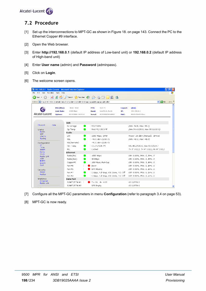
7.2 Procedure
[1] Set up the interconnections to MPT-GC as shown in Figure 18. on page 143. Connect the PC to theEthernet Copper #9 interface.
[2] Open the Web browser.
[3] Enter http://192.168.0.1 (default IP address of Low-band unit) or 192.168.0.2 (default IP addressof High-band unit)
[4] Enter User name (admin) and Password (adminpass).
[5] Click on Login.
[6] The welcome screen opens.
[7] Configure all the MPT-GC parameters in menu Configuration (refer to paragraph 3.4 on page 53).
[8] MPT-GC is now ready.
User Manual
Provisioning
9500 MPR for ANSI and ETSI
3DB19025AAAA Issue 2198/234
8 Line–up and commissioningThis chapter details all phases necessary for the equipment line–up and commissioning.
Subject On page
Introduction 200
General 200
Conventions 201
Summary of the line–up, commissioning, and acceptance phases 201
PC connection 202
How to access the remote MPT-GC 202
Commissioning of STATION A – phase 1 (turn up) 203
Commissioning of STATION B – phase 1 (turn up) 204
Fine antenna alignment and preliminary checks – Stations A & B 204
End of commissioning phase 1 (turn up) in STATION A 205
Commissioning station A – phase 2 (acceptance test) 206
Commissioning station B – phase 2 (acceptance test) 212
Annex A: fine antenna alignment 213
User Manual
Line–up and commissioning
9500 MPR for ANSI and ETSI
3DB19025AAAA Issue 2 199/234
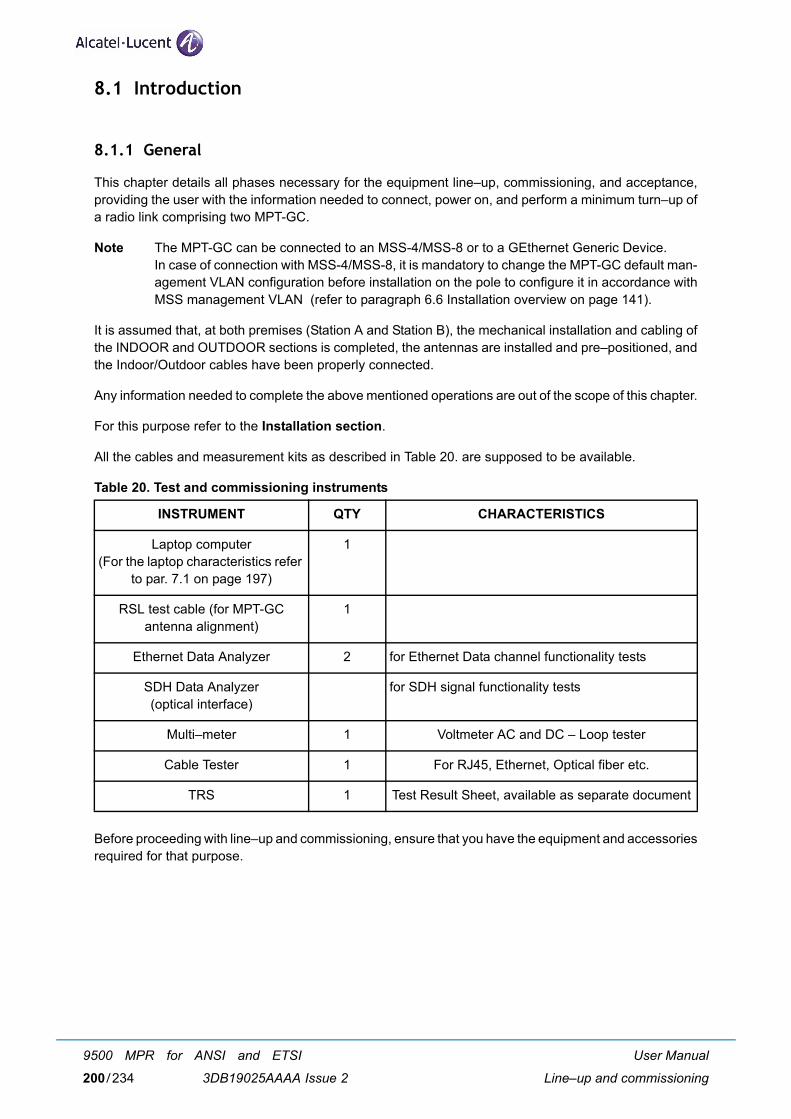
8.1 Introduction
8.1.1 General
This chapter details all phases necessary for the equipment line–up, commissioning, and acceptance,providing the user with the information needed to connect, power on, and perform a minimum turn–up ofa radio link comprising two MPT-GC.
Note The MPT-GC can be connected to an MSS-4/MSS-8 or to a GEthernet Generic Device.In case of connection with MSS-4/MSS-8, it is mandatory to change the MPT-GC default man-agement VLAN configuration before installation on the pole to configure it in accordance withMSS management VLAN (refer to paragraph 6.6 Installation overview on page 141).
It is assumed that, at both premises (Station A and Station B), the mechanical installation and cabling ofthe INDOOR and OUTDOOR sections is completed, the antennas are installed and pre–positioned, andthe Indoor/Outdoor cables have been properly connected.
Any information needed to complete the above mentioned operations are out of the scope of this chapter.
For this purpose refer to the Installation section.
All the cables and measurement kits as described in Table 20. are supposed to be available.
Table 20. Test and commissioning instruments
Before proceeding with line–up and commissioning, ensure that you have the equipment and accessoriesrequired for that purpose.
INSTRUMENT QTY CHARACTERISTICS
Laptop computer(For the laptop characteristics refer
to par. 7.1 on page 197)
1
RSL test cable (for MPT-GC antenna alignment)
1
Ethernet Data Analyzer 2 for Ethernet Data channel functionality tests
SDH Data Analyzer (optical interface)
for SDH signal functionality tests
Multi–meter 1 Voltmeter AC and DC – Loop tester
Cable Tester 1 For RJ45, Ethernet, Optical fiber etc.
TRS 1 Test Result Sheet, available as separate document
User Manual
Line–up and commissioning
9500 MPR for ANSI and ETSI
3DB19025AAAA Issue 2200/234
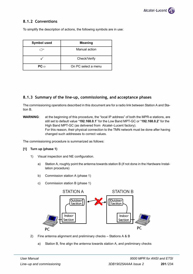
8.1.2 Conventions
To simplify the description of actions, the following symbols are in use:
8.1.3 Summary of the line–up, commissioning, and acceptance phases
The commissioning operations described in this document are for a radio link between Station A and Sta-tion B.
WARNING: at the beginning of this procedure, the “local IP address” of both the MPR-e stations, arestill set to default value “192.168.0.1” for the Low Band MPT-GC or “192.168.0.2” for the High Band MPT-GC (as delivered from Alcatel–Lucent factory). For this reason, their physical connection to the TMN network must be done after havingchanged such addresses to correct values.
The commissioning procedure is summarized as follows:
[1] Turn up (phase 1)
1) Visual inspection and NE configuration.
a) Station A, roughly point the antenna towards station B (if not done in the Hardware Instal-lation procedure)
b) Commission station A (phase 1)
c) Commission station B (phase 1)
2) Fine antenna alignment and preliminary checks – Stations A & B
a) Station B, fine align the antenna towards station A, and preliminary checks
Symbol used Meaning
Manual action
Check/Verify
PC⇒ On PC select a menu
User Manual
Line–up and commissioning
9500 MPR for ANSI and ETSI
3DB19025AAAA Issue 2 201/234
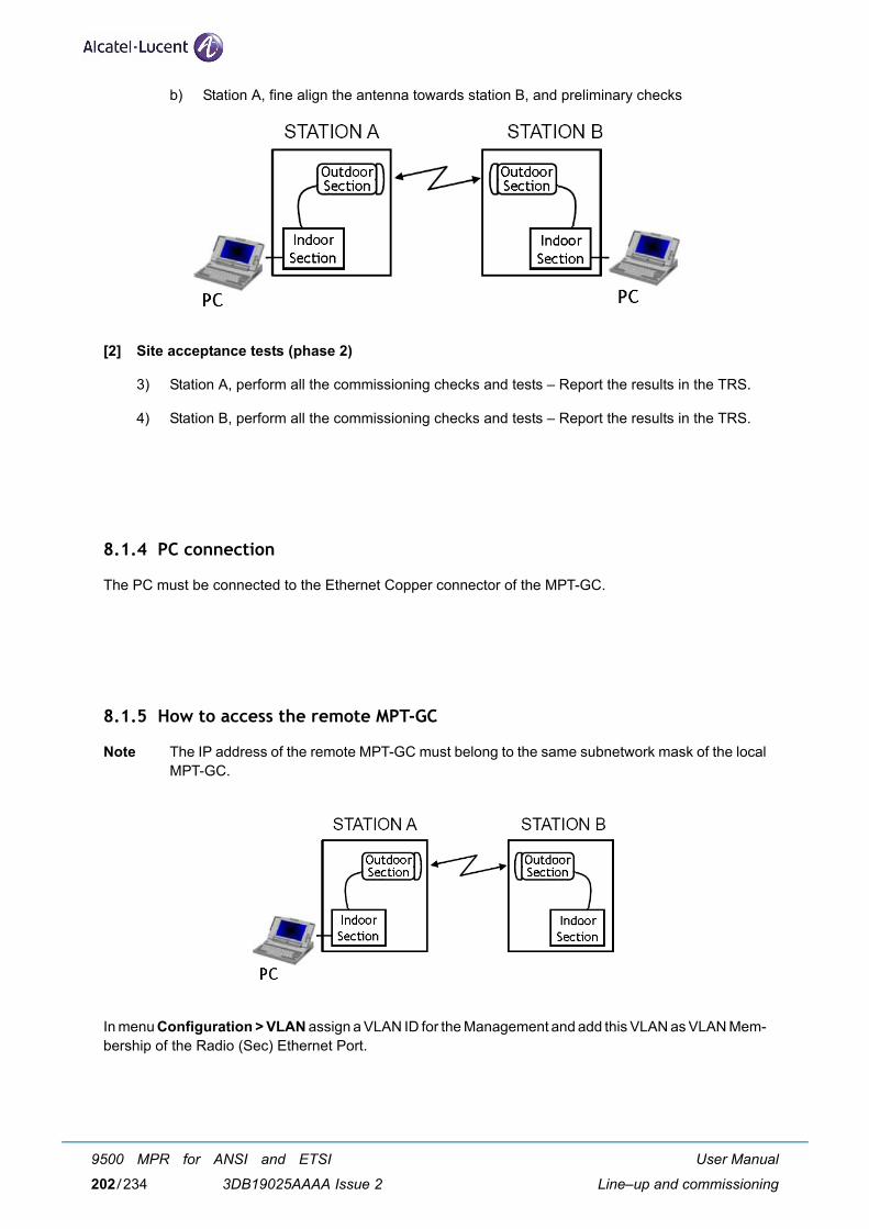
b) Station A, fine align the antenna towards station B, and preliminary checks
[2] Site acceptance tests (phase 2)
3) Station A, perform all the commissioning checks and tests – Report the results in the TRS.
4) Station B, perform all the commissioning checks and tests – Report the results in the TRS.
8.1.4 PC connection
The PC must be connected to the Ethernet Copper connector of the MPT-GC.
8.1.5 How to access the remote MPT-GC
Note The IP address of the remote MPT-GC must belong to the same subnetwork mask of the localMPT-GC.
In menu Configuration > VLAN assign a VLAN ID for the Management and add this VLAN as VLAN Mem-bership of the Radio (Sec) Ethernet Port.
User Manual
Line–up and commissioning
9500 MPR for ANSI and ETSI
3DB19025AAAA Issue 2202/234
8.2 Commissioning of STATION A – phase 1 (turn up)
8.2.1 Turn–on preliminary operations
ALL THESE OPERATIONS ARE PERFORMED WITH THE POWER OFF
The antenna of station A (or B) is pointed towards station B (or A) the best as possible (use compass if necessary).
The hardware configuration of the equipment corresponds to the expected one.
Make visual inspection for equipment installation and cabling:
• Ground connections
• Power supply voltage present with the correct polarity at the MPT-GC power supply connector
• Ethernet connections between the GEthernet Generic Device and MPT-GC
• STM-1/STM-4 connections (if required) between the SDH equipment and MPT-GC.
• Indoor-Outdoor cables grounding kit connections
• MPT-GC ground connections (In the case of a non–integrated antenna, the antenna and theMPT-GC must be ground connected)
• MPT-GC cables connectors waterproofing.
8.2.2 Powering up the MPT-GC
Proceed as follows:
[1] Connect locally the PC to the Copper #9 port of MPT-GC.
[2] Switch on the MPT-GC.
[3] Start-up the PC and wait for the Welcome screen.
– Where necessary, switch OFF the power supply before disconnecting the earth connection,
– Do not connect instruments directly to the ODU cable connector since the connector car-ries DC voltage used to supply the ODU.
User Manual
Line–up and commissioning
9500 MPR for ANSI and ETSI
3DB19025AAAA Issue 2 203/234
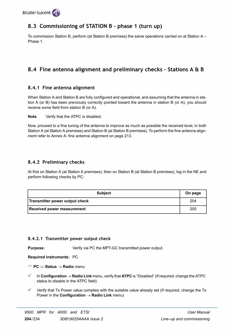
8.3 Commissioning of STATION B – phase 1 (turn up)
To commission Station B, perform (at Station B premises) the same operations carried on at Station A –Phase 1.
8.4 Fine antenna alignment and preliminary checks – Stations A & B
8.4.1 Fine antenna alignment
When Station A and Station B are fully configured and operational, and assuming that the antenna in sta-tion A (or B) has been previously correctly pointed toward the antenna in station B (or A), you shouldreceive some field from station B (or A).
Note Verify that the ATPC is disabled.
Now, proceed to a fine tuning of the antenna to improve as much as possible the received level, in bothStation A (at Station A premises) and Station B (at Station B premises). To perform the fine antenna align-ment refer to Annex A: fine antenna alignment on page 213.
8.4.2 Preliminary checks
At first on Station A (at Station A premises), then on Station B (at Station B premises), log in the NE andperform following checks by PC:
8.4.2.1 Transmitter power output check
Purpose: Verify via PC the MPT-GC transmitted power output.
Required instruments: PC
PC ⇒ Status → Radio menu
In Configuration → Radio Link menu, verify that ATPC is “Disabled” (If required, change the ATPC status to disable in the ATPC field)
Verify that Tx Power value complies with the suitable value already set (If required, change the TxPower in the Configuration → Radio Link menu)
Subject On page
Transmitter power output check 204
Received power measurement 205
User Manual
Line–up and commissioning
9500 MPR for ANSI and ETSI
3DB19025AAAA Issue 2204/234
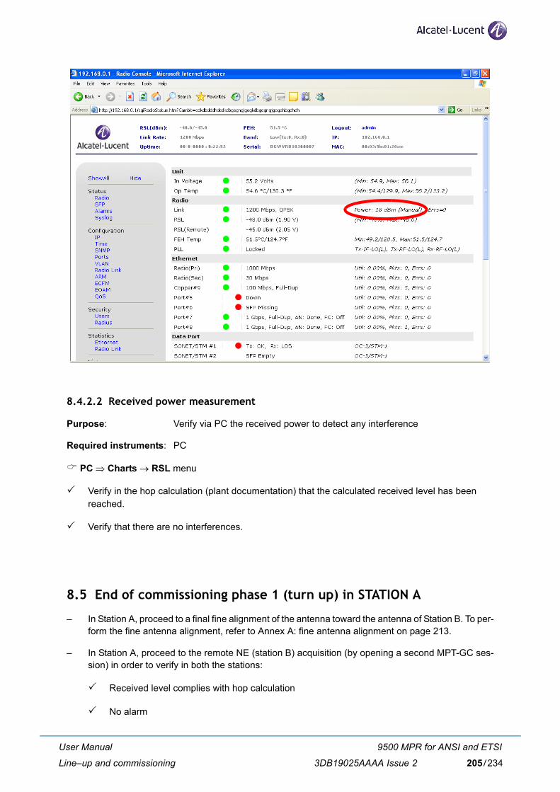
8.4.2.2 Received power measurement
Purpose: Verify via PC the received power to detect any interference
Required instruments: PC
PC ⇒ Charts → RSL menu
Verify in the hop calculation (plant documentation) that the calculated received level has beenreached.
Verify that there are no interferences.
8.5 End of commissioning phase 1 (turn up) in STATION A
– In Station A, proceed to a final fine alignment of the antenna toward the antenna of Station B. To per-form the fine antenna alignment, refer to Annex A: fine antenna alignment on page 213.
– In Station A, proceed to the remote NE (station B) acquisition (by opening a second MPT-GC ses-sion) in order to verify in both the stations:
Received level complies with hop calculation
No alarm
User Manual
Line–up and commissioning
9500 MPR for ANSI and ETSI
3DB19025AAAA Issue 2 205/234
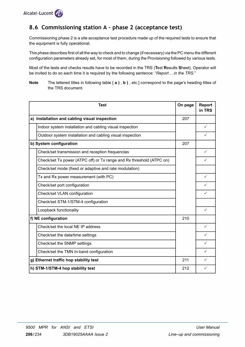
8.6 Commissioning station A – phase 2 (acceptance test)
Commissioning phase 2 is a site acceptance test procedure made up of the required tests to ensure thatthe equipment is fully operational.
This phase describes first of all the way to check and to change (if necessary) via the PC menu the differentconfiguration parameters already set, for most of them, during the Provisioning followed by various tests.
Most of the tests and checks results have to be recorded in the TRS (Test Results Sheet). Operator willbe invited to do so each time it is required by the following sentence: “Report… in the TRS.”
Note The lettered titles in following table [ a ) , b ) , etc.] correspond to the page’s heading titles ofthe TRS document.
Test On page Report in TRS
a) Installation and cabling visual inspection 207
Indoor system installation and cabling visual inspection
Outdoor system installation and cabling visual inspection
b) System configuration 207
Check/set transmission and reception frequencies
Check/set Tx power (ATPC off) or Tx range and Rx threshold (ATPC on)
Check/set mode (fixed or adaptive and rate modulation)
Tx and Rx power measurement (with PC)
Check/set port configuration
Check/set VLAN configuration
Check/set STM-1/STM-4 configuration
Loopback functionality
f) NE configuration 210
Check/set the local NE IP address
Check/set the data/time settings
Check/set the SNMP settings
Check/set the TMN In-band configuration
g) Ethernet traffic hop stability test 211
h) STM-1/STM-4 hop stability test 212
User Manual
Line–up and commissioning
9500 MPR for ANSI and ETSI
3DB19025AAAA Issue 2206/234
8.6.1 Installation and cabling visual inspection
8.6.1.1 Indoor system installation and cabling visual inspection
See and fill the indoor inspection check list in the TRS.
8.6.1.2 Outdoor system installation and cabling visual inspection
See and fill the outdoor inspection check list in the TRS.
8.6.2 System configuration
Purpose: Verify via PC the configuration of the Local Station.
Required Instruments: PC
Procedure: Connect PC to the MPT-GC
8.6.2.1 Check/set transmission and reception frequencies
PC ⇒ Menu Configuration → Radio Link
Report the Tx and the Rx frequencies in the TRS.
If required, change the Tx frequency. Rx Freq. will be automatically adjusted.
8.6.2.2 Check/set Tx power (ATPC off) or Tx range and Rx threshold (ATPC on)
PC ⇒ Menu Configuration → Radio Link
ATPC “Disabled”
Report the ATPC “Disabled” status, Tx nominal Power and Tx Power setting into the TRS.
ATPC “Enabled”
Report the ATPC “Enabled” status, ATPC Range and ATPC RX Threshold setting in the TRS.
If required, change ATPC Mode or ATPC Range or ATPC Rx Threshold then → Apply
8.6.2.3 Check/set mode (fixed or adaptive and rate modulation)
PC ⇒ Menu Configuration → Radio Link
If required, change any parameter.
Report the parameters in the TRS.
User Manual
Line–up and commissioning
9500 MPR for ANSI and ETSI
3DB19025AAAA Issue 2 207/234
8.6.2.4 Tx and Rx power measurement (with PC)
Purpose: Verify via PC the Transmitted (PTx) and Received (PRx) power.
PC ⇒ Menu Status → Radio
Report the Current Tx Local End (PTx) and the current Rx Local End (PRx) in the TRS.
8.6.2.5 Check/set port configuration
PC ⇒ Menu → Port
Report the port configuration in the TRS.
8.6.2.6 Check/set VLAN configuration
PC → Menu Configuration → VLAN
Check/set all the VLAN membership regarding the Ethernet switch.
Report in the TRS.
8.6.2.7 Check/set STM-1/STM-4 configuration
PC ⇒ Menu Configuration → Ports
STM-1/STM-4 ports are port# 1 to port# 4.
If it is necessary, change the STM-1/STM-4 parameters.
Report in the TRS.
8.6.2.7.1 STM-1/STM-4 point to point loop test
Purpose: Verify the point to point STM-1/STM-4 quality
Required instruments: SDH Data Analyzer
Procedure: Connect Pattern Generator/Error Detector on STM-1/STM-4 port (At the Station DDF)
Report the result in the TRS.
User Manual
Line–up and commissioning
9500 MPR for ANSI and ETSI
3DB19025AAAA Issue 2208/234
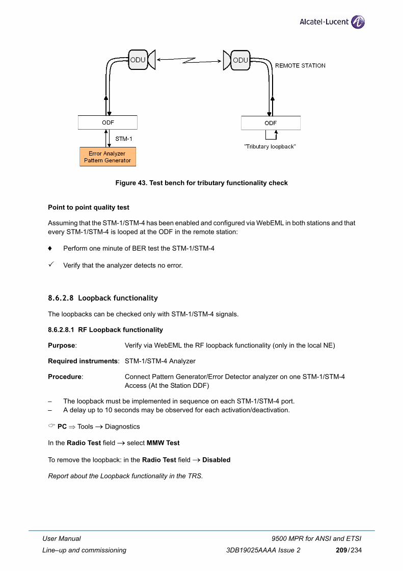
Figure 43. Test bench for tributary functionality check
Point to point quality test
Assuming that the STM-1/STM-4 has been enabled and configured via WebEML in both stations and thatevery STM-1/STM-4 is looped at the ODF in the remote station:
♦ Perform one minute of BER test the STM-1/STM-4
Verify that the analyzer detects no error.
8.6.2.8 Loopback functionality
The loopbacks can be checked only with STM-1/STM-4 signals.
8.6.2.8.1 RF Loopback functionality
Purpose: Verify via WebEML the RF loopback functionality (only in the local NE)
Required instruments: STM-1/STM-4 Analyzer
Procedure: Connect Pattern Generator/Error Detector analyzer on one STM-1/STM-4 Access (At the Station DDF)
– The loopback must be implemented in sequence on each STM-1/STM-4 port.– A delay up to 10 seconds may be observed for each activation/deactivation.
PC ⇒ Tools → Diagnostics
In the Radio Test field → select MMW Test
To remove the loopback: in the Radio Test field → Disabled
Report about the Loopback functionality in the TRS.
User Manual
Line–up and commissioning
9500 MPR for ANSI and ETSI
3DB19025AAAA Issue 2 209/234
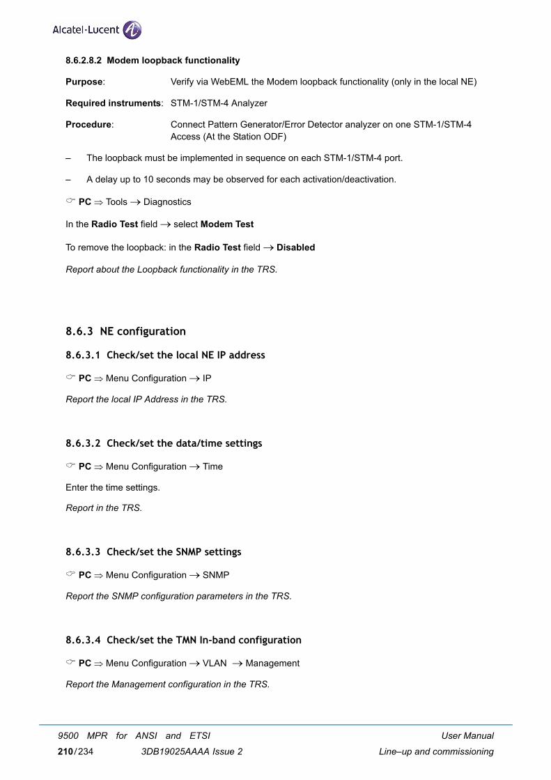
8.6.2.8.2 Modem loopback functionality
Purpose: Verify via WebEML the Modem loopback functionality (only in the local NE)
Required instruments: STM-1/STM-4 Analyzer
Procedure: Connect Pattern Generator/Error Detector analyzer on one STM-1/STM-4 Access (At the Station ODF)
– The loopback must be implemented in sequence on each STM-1/STM-4 port.
– A delay up to 10 seconds may be observed for each activation/deactivation.
PC ⇒ Tools → Diagnostics
In the Radio Test field → select Modem Test
To remove the loopback: in the Radio Test field → Disabled
Report about the Loopback functionality in the TRS.
8.6.3 NE configuration
8.6.3.1 Check/set the local NE IP address
PC ⇒ Menu Configuration → IP
Report the local IP Address in the TRS.
8.6.3.2 Check/set the data/time settings
PC ⇒ Menu Configuration → Time
Enter the time settings.
Report in the TRS.
8.6.3.3 Check/set the SNMP settings
PC ⇒ Menu Configuration → SNMP
Report the SNMP configuration parameters in the TRS.
8.6.3.4 Check/set the TMN In-band configuration
PC ⇒ Menu Configuration → VLAN → Management
Report the Management configuration in the TRS.
User Manual
Line–up and commissioning
9500 MPR for ANSI and ETSI
3DB19025AAAA Issue 2210/234
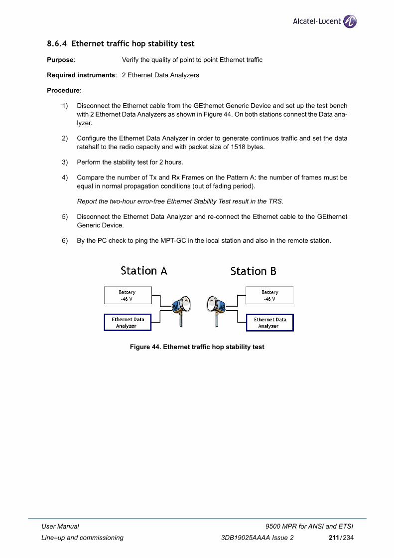
8.6.4 Ethernet traffic hop stability test
Purpose: Verify the quality of point to point Ethernet traffic
Required instruments: 2 Ethernet Data Analyzers
Procedure:
1) Disconnect the Ethernet cable from the GEthernet Generic Device and set up the test benchwith 2 Ethernet Data Analyzers as shown in Figure 44. On both stations connect the Data ana-lyzer.
2) Configure the Ethernet Data Analyzer in order to generate continuos traffic and set the dataratehalf to the radio capacity and with packet size of 1518 bytes.
3) Perform the stability test for 2 hours.
4) Compare the number of Tx and Rx Frames on the Pattern A: the number of frames must beequal in normal propagation conditions (out of fading period).
Report the two-hour error-free Ethernet Stability Test result in the TRS.
5) Disconnect the Ethernet Data Analyzer and re-connect the Ethernet cable to the GEthernetGeneric Device.
6) By the PC check to ping the MPT-GC in the local station and also in the remote station.
Figure 44. Ethernet traffic hop stability test
User Manual
Line–up and commissioning
9500 MPR for ANSI and ETSI
3DB19025AAAA Issue 2 211/234
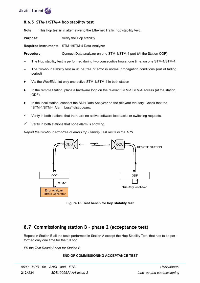
8.6.5 STM-1/STM-4 hop stability test
Note This hop test is in alternative to the Ethernet Traffic hop stability test.
Purpose: Verify the Hop stability
Required instruments: STM-1/STM-4 Data Analyzer
Procedure: Connect Data analyzer on one STM-1/STM-4 port (At the Station ODF)
– The Hop stability test is performed during two consecutive hours, one time, on one STM-1/STM-4.
– The two-hour stability test must be free of error in normal propagation conditions (out of fadingperiod)
♦ Via the WebEML, let only one active STM-1/STM-4 in both station
♦ In the remote Station, place a hardware loop on the relevant STM-1/STM-4 access (at the stationODF).
♦ In the local station, connect the SDH Data Analyzer on the relevant tributary. Check that the “STM-1/STM-4 Alarm Loss” disappears.
Verify in both stations that there are no active software loopbacks or switching requests.
Verify in both stations that none alarm is showing.
Report the two-hour error-free of error Hop Stability Test result in the TRS.
Figure 45. Test bench for hop stability test
8.7 Commissioning station B – phase 2 (acceptance test)
Repeat in Station B all the tests performed in Station A except the Hop Stability Test, that has to be per-formed only one time for the full hop.
Fill the Test Result Sheet for Station B
END OF COMMISSIONING ACCEPTANCE TEST
User Manual
Line–up and commissioning
9500 MPR for ANSI and ETSI
3DB19025AAAA Issue 2212/234
8.8 Annex A: fine antenna alignment
Safety requirements for workers on antenna pole, and microwave radiations (EMF norms)
Antenna pre–pointing should have been done during equipment hardware installation.
This annex explains how to carry out the antenna fine alignment.
8.8.1 Antenna alignment
8.8.1.1 RSL test cable
The alignment procedure is optimized through the use of the provided test cable. This test cable isdesigned for use with a digital voltmeter (not provided) to read the Link Quality and Receive Signal Level(RSL) voltage generated by the radio's receiver. See Figure 46.
Figure 46. Supplied test cable for measuring link quality and receive signal level voltages
1) To read the RSL value of the radio, insert GND (ground) and RSL banana plugs into the volt-meter. Note the RSL voltage. The voltage may be fluctuating; in this case, note the maximumvalue seen.
2) When the radio is put into 'Alignment' mode as described in the following sections, the Qualityvoltage connector will now read the remote radio's RSL voltage.
SAFETY RULESWhen operating on the antenna pole, strictly follow cautions. In particular do not stand on the antenna axis and be aware of the complianceboundaries.
User Manual
Line–up and commissioning
9500 MPR for ANSI and ETSI
3DB19025AAAA Issue 2 213/234
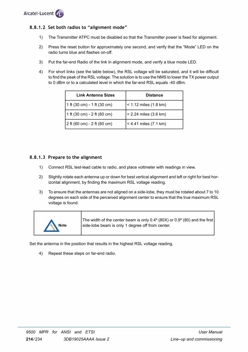
8.8.1.2 Set both radios to “alignment mode”
1) The Transmitter ATPC must be disabled so that the Transmitter power is fixed for alignment.
2) Press the reset button for approximately one second, and verify that the “Mode” LED on theradio turns blue and flashes on-off.
3) Put the far-end Radio of the link in alignment mode, and verify a blue mode LED.
4) For short links (see the table below), the RSL voltage will be saturated, and it will be difficultto find the peak of the RSL voltage. The solution is to use the NMS to lower the TX power outputto 0 dBm or to a calculated level in which the far-end RSL equals -40 dBm.
8.8.1.3 Prepare to the alignment
1) Connect RSL test-lead cable to radio, and place voltmeter with readings in view.
2) Slightly rotate each antenna up or down for best vertical alignment and left or right for best hor-izontal alignment, by finding the maximum RSL voltage reading.
3) To ensure that the antennas are not aligned on a side-lobe, they must be rotated about 7 to 10degrees on each side of the perceived alignment center to ensure that the true maximum RSLvoltage is found.
Set the antenna in the position that results in the highest RSL voltage reading.
4) Repeat these steps on far-end radio.
Link Antenna Sizes Distance
1 ft (30 cm) - 1 ft (30 cm) < 1.12 miles (1.8 km)
1 ft (30 cm) - 2 ft (60 cm) < 2.24 miles (3.6 km)
2 ft (60 cm) - 2 ft (60 cm) < 4.41 miles (7.1 km)
The width of the center beam is only 0.4º (80X) or 0.9º (80) and the firstside-lobe beam is only 1 degree off from center.
User Manual
Line–up and commissioning
9500 MPR for ANSI and ETSI
3DB19025AAAA Issue 2214/234
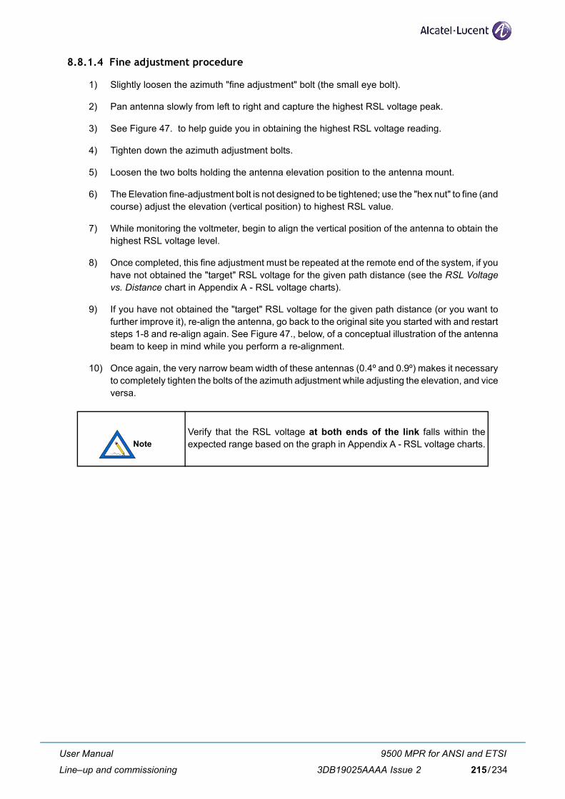
8.8.1.4 Fine adjustment procedure
1) Slightly loosen the azimuth "fine adjustment" bolt (the small eye bolt).
2) Pan antenna slowly from left to right and capture the highest RSL voltage peak.
3) See Figure 47. to help guide you in obtaining the highest RSL voltage reading.
4) Tighten down the azimuth adjustment bolts.
5) Loosen the two bolts holding the antenna elevation position to the antenna mount.
6) The Elevation fine-adjustment bolt is not designed to be tightened; use the "hex nut" to fine (andcourse) adjust the elevation (vertical position) to highest RSL value.
7) While monitoring the voltmeter, begin to align the vertical position of the antenna to obtain thehighest RSL voltage level.
8) Once completed, this fine adjustment must be repeated at the remote end of the system, if youhave not obtained the "target" RSL voltage for the given path distance (see the RSL Voltagevs. Distance chart in Appendix A - RSL voltage charts).
9) If you have not obtained the "target" RSL voltage for the given path distance (or you want tofurther improve it), re-align the antenna, go back to the original site you started with and restartsteps 1-8 and re-align again. See Figure 47., below, of a conceptual illustration of the antennabeam to keep in mind while you perform a re-alignment.
10) Once again, the very narrow beam width of these antennas (0.4º and 0.9º) makes it necessaryto completely tighten the bolts of the azimuth adjustment while adjusting the elevation, and viceversa.
Verify that the RSL voltage at both ends of the link falls within theexpected range based on the graph in Appendix A - RSL voltage charts.
User Manual
Line–up and commissioning
9500 MPR for ANSI and ETSI
3DB19025AAAA Issue 2 215/234
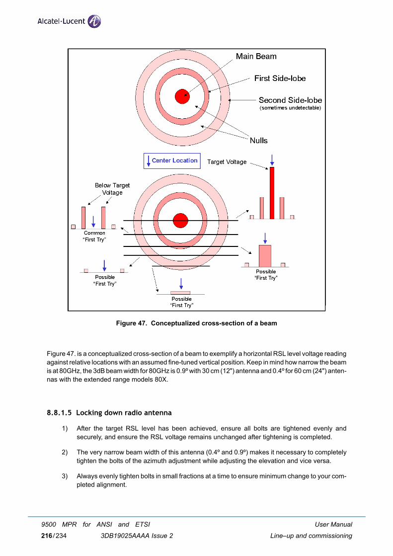
Figure 47. Conceptualized cross-section of a beam
Figure 47. is a conceptualized cross-section of a beam to exemplify a horizontal RSL level voltage readingagainst relative locations with an assumed fine-tuned vertical position. Keep in mind how narrow the beamis at 80GHz, the 3dB beam width for 80GHz is 0.9º with 30 cm (12") antenna and 0.4º for 60 cm (24") anten-nas with the extended range models 80X.
8.8.1.5 Locking down radio antenna
1) After the target RSL level has been achieved, ensure all bolts are tightened evenly andsecurely, and ensure the RSL voltage remains unchanged after tightening is completed.
2) The very narrow beam width of this antenna (0.4º and 0.9º) makes it necessary to completelytighten the bolts of the azimuth adjustment while adjusting the elevation and vice versa.
3) Always evenly tighten bolts in small fractions at a time to ensure minimum change to your com-pleted alignment.
User Manual
Line–up and commissioning
9500 MPR for ANSI and ETSI
3DB19025AAAA Issue 2216/234
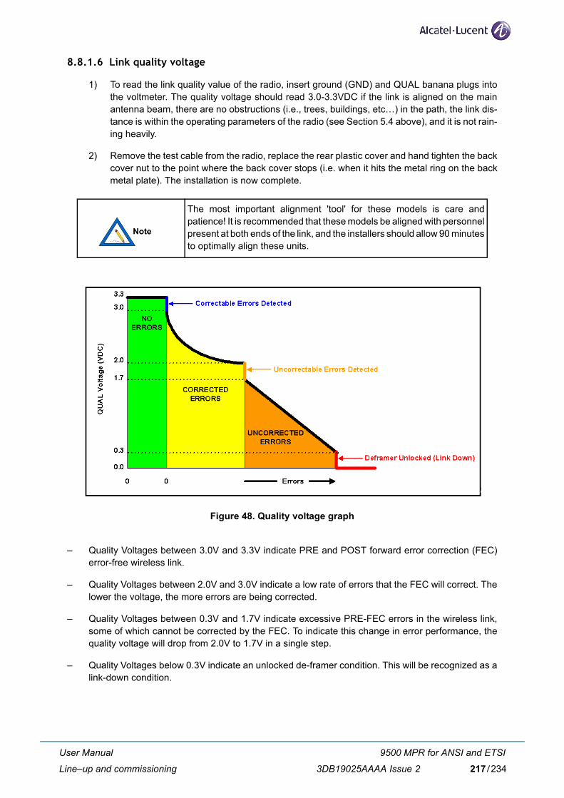
8.8.1.6 Link quality voltage
1) To read the link quality value of the radio, insert ground (GND) and QUAL banana plugs intothe voltmeter. The quality voltage should read 3.0-3.3VDC if the link is aligned on the mainantenna beam, there are no obstructions (i.e., trees, buildings, etc…) in the path, the link dis-tance is within the operating parameters of the radio (see Section 5.4 above), and it is not rain-ing heavily.
2) Remove the test cable from the radio, replace the rear plastic cover and hand tighten the backcover nut to the point where the back cover stops (i.e. when it hits the metal ring on the backmetal plate). The installation is now complete.
Figure 48. Quality voltage graph
– Quality Voltages between 3.0V and 3.3V indicate PRE and POST forward error correction (FEC)error-free wireless link.
– Quality Voltages between 2.0V and 3.0V indicate a low rate of errors that the FEC will correct. Thelower the voltage, the more errors are being corrected.
– Quality Voltages between 0.3V and 1.7V indicate excessive PRE-FEC errors in the wireless link,some of which cannot be corrected by the FEC. To indicate this change in error performance, thequality voltage will drop from 2.0V to 1.7V in a single step.
– Quality Voltages below 0.3V indicate an unlocked de-framer condition. This will be recognized as alink-down condition.
The most important alignment 'tool' for these models is care andpatience! It is recommended that these models be aligned with personnelpresent at both ends of the link, and the installers should allow 90 minutesto optimally align these units.
User Manual
Line–up and commissioning
9500 MPR for ANSI and ETSI
3DB19025AAAA Issue 2 217/234
8.8.1.7 Clear both radios from 'alignment mode'.
1) The Transmitter ATPC must be re-enabled so that the transmitter power is automatically con-trolled.
2) Press the reset button for approximately one second and verify that the 'Mode" LED on the radioturns from blue to off.
3) Put the far-end radio of the link in alignment mode and verify that the flashing blue 'Mode' LEDis off.
If you cannot obtain a good quality voltage, and you have obtained the target RSL, contact the TechnicalSupport.
At this point, open the Status page from the unit's NMS interface and ensure the Radio TX and RX is oper-ating at expected SONET and/or 1000 Mbps for both radios.
1) Go to Statistics page and reset the statistics for each radio end.
2) Perform a ping test. Open two command line windows, and ping the local and remote man-agement agent. Factory default IPs are; 192.168.0.1 for low-band and 192.168.0.2 for high-band. Perform a ping to both ends and wait a few minutes, ensure you are getting responsesfrom the local and remote management agents.
3) Review the Statistics page results and ensure packets are being transmitted, received, andthere are no excessive error conditions.
User Manual
Line–up and commissioning
9500 MPR for ANSI and ETSI
3DB19025AAAA Issue 2218/234
9 Maintenance and troubleshooting
9.1 Normal operation
During normal operation, the following conditions should exist at the radio:
– The Power LED should be lit-solid green;
– The Mode LED should be 'OFF';
– The Radio Link Up LED should be lit-solid green;
– The 'Alarm' LED should be OFF;
– The Link Quality BER voltage normally should be 3.0-3.3V when it is not raining.
9.2 Maintenance
The MPT-GC system does not require periodic maintenance. However, each end of the link should beperiodically inspected for visible damage or excessive accumulation of dirt on the antenna's radome.
9.3 Troubleshooting
Table 21. provides a summary of possible problems you might encounter while installing an Alcatel-LucentMPT-GC link, along with possible causes and their solutions.
Table 21. Troubleshooting
Problem Possible cause Resolution
No power to radio Wrong polarity of supply voltage Use a DVM to determine the polarityand voltage on the DC cable.
The supply voltage measured at theradio (when connected) is below min-imum VDC specification
The cable run is too long or the cablegauge is too small. Shorten the lengthof the cable or use larger gaugecable.
User Manual
Maintenance and troubleshooting
9500 MPR for ANSI and ETSI
3DB19025AAAA Issue 2 219/234
RSL voltage lower thanexpected
Incorrect calculation of link distance Verify that the calculation tool usedand the GPS used both have thesame annotation system (degreehours minutes seconds or degreewith a decimal value)
Antennas aligned on side lobes Repeat antenna alignment proce-dure.
Radios set to different polarizations Verify that both radios are mounted inthe same polarization. (See section6.7.2)
Installed two high or two low bandradios in one link
Verify that one end of the link is highand the other end is a low band radio
Test cable not inserted into test porton radio properly
Ensure test cable is completedinserted into the test port of the radio.
Make sure that you are using correctRSL voltage table.
If table is for a different product, con-sult the correct product manual.
Low link quality voltage Antennas are not aligned for maxi-mum RSL
Verify antenna alignment, useinstructions provided in sections6.7.2.
Interference This is unusual unless other radiosusing the same spectrum are co-located.Check for possible interference byturning off the radio at the other end ofthe link and verify the RSL voltage onthe local site drops below 0.2V.
Test cable not inserted into test porton radio properly
Ensure test cable is completelyinserted into the test port of the radio.
Cannot connect to radionetwork managementagent
Incorrect IP address configuration onradio or PC
Verify Ethernet connections are up,verify IP address, check for IPaddress conflicts, clear ARP cacheon PC.
Management agent access isblocked through one or more inter-faces
Try accessing agent through otherinterfaces (fiber, copper, radio link).
Perform hard reset on radio unit Attempt to access on default addressvia copper port.
Problem Possible cause Resolution
User Manual
Maintenance and troubleshooting
9500 MPR for ANSI and ETSI
3DB19025AAAA Issue 2220/234
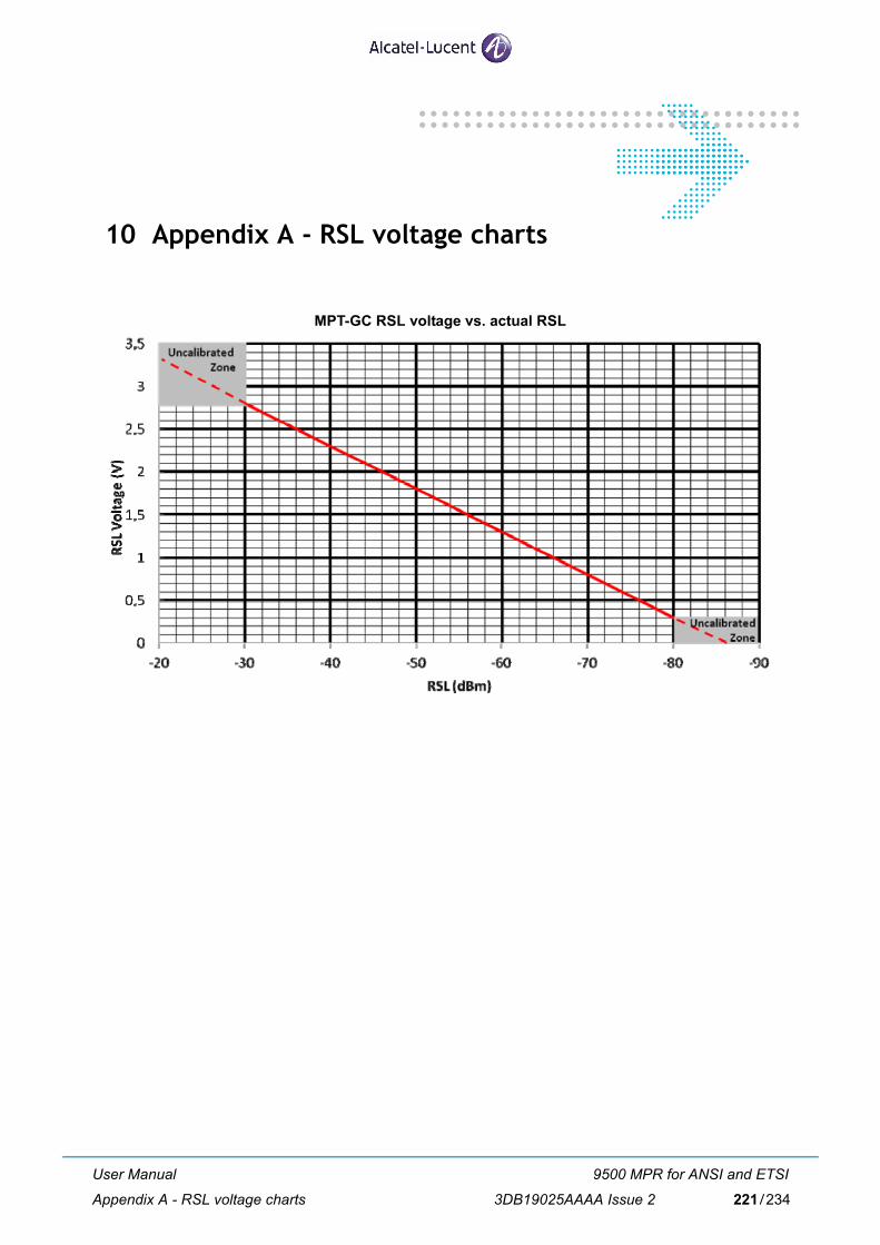
10 Appendix A - RSL voltage charts
MPT-GC RSL voltage vs. actual RSL
User Manual
Appendix A - RSL voltage charts
9500 MPR for ANSI and ETSI
3DB19025AAAA Issue 2 221/234

User Manual
Appendix A - RSL voltage charts
9500 MPR for ANSI and ETSI
3DB19025AAAA Issue 2222/234
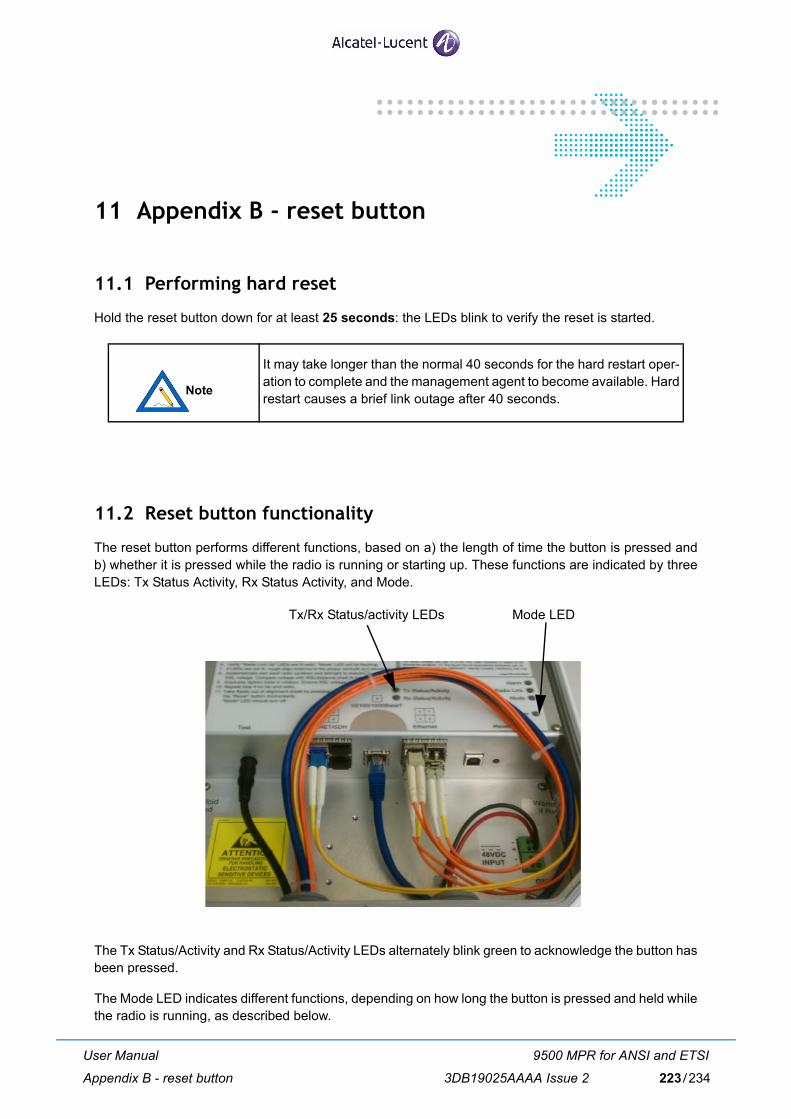
11 Appendix B - reset button
11.1 Performing hard reset
Hold the reset button down for at least 25 seconds: the LEDs blink to verify the reset is started.
11.2 Reset button functionality
The reset button performs different functions, based on a) the length of time the button is pressed andb) whether it is pressed while the radio is running or starting up. These functions are indicated by threeLEDs: Tx Status Activity, Rx Status Activity, and Mode.
The Tx Status/Activity and Rx Status/Activity LEDs alternately blink green to acknowledge the button hasbeen pressed.
The Mode LED indicates different functions, depending on how long the button is pressed and held whilethe radio is running, as described below.
It may take longer than the normal 40 seconds for the hard restart oper-ation to complete and the management agent to become available. Hardrestart causes a brief link outage after 40 seconds.
Tx/Rx Status/activity LEDs Mode LED
User Manual
Appendix B - reset button
9500 MPR for ANSI and ETSI
3DB19025AAAA Issue 2 223/234
11.2.1 Changing ATPC mode
If the button is pressed and held, then released between 1-10 seconds, the ATPC mode toggles betweenManual and Automatic. The Mode LED blinks blue in Manual mode and turns off in Automatic mode.
Analog output is also tied to ATPC mode. When the ATPC mode is set to Manual, the analog output rep-resents remote RSL voltage. When set to Automatic mode, the analog output represents local quality volt-age.
11.2.2 Hard restart
If the button is pressed and held, then released between 11-20 seconds, the radio performs a hard restartequivalent to the Web interface (the radio is restarted, and current configuration settings are maintained).The Mode LED illuminates solid red.
11.2.3 Factory hard reset
If the button is pressed and held, then released between 21-30 seconds, the Web interface is restarted(the radio is restarted and defaults to factory configuration settings). The Mode LED blinks red.
If the button is pressed and held between 30-60 seconds, no actionoccurs.
User Manual
Appendix B - reset button
9500 MPR for ANSI and ETSI
3DB19025AAAA Issue 2224/234
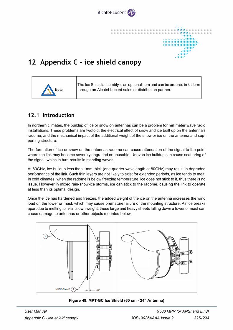
12 Appendix C - ice shield canopy
12.1 Introduction
In northern climates, the buildup of ice or snow on antennas can be a problem for millimeter wave radioinstallations. These problems are twofold: the electrical effect of snow and ice built up on the antenna'sradome; and the mechanical impact of the additional weight of the snow or ice on the antenna and sup-porting structure.
The formation of ice or snow on the antennas radome can cause attenuation of the signal to the pointwhere the link may become severely degraded or unusable. Uneven ice buildup can cause scattering ofthe signal, which in turn results in standing waves.
At 80GHz, ice buildup less than 1mm thick (one-quarter wavelength at 80GHz) may result in degradedperformance of the link. Such thin layers are not likely to exist for extended periods, as ice tends to melt.In cold climates, when the radome is below freezing temperature, ice does not stick to it, thus there is noissue. However in mixed rain-snow-ice storms, ice can stick to the radome, causing the link to operateat less than its optimal design.
Once the ice has hardened and freezes, the added weight of the ice on the antenna increases the windload on the tower or mast, which may cause premature failure of the mounting structure. As ice breaksapart due to melting, or via its own weight, these large and heavy sheets falling down a tower or mast cancause damage to antennas or other objects mounted below.
Figure 49. MPT-GC Ice Shield (60 cm - 24" Antenna)
The Ice Shield assembly is an optional item and can be ordered in kit formthrough an Alcatel-Lucent sales or distribution partner.
User Manual
Appendix C - ice shield canopy
9500 MPR for ANSI and ETSI
3DB19025AAAA Issue 2 225/234
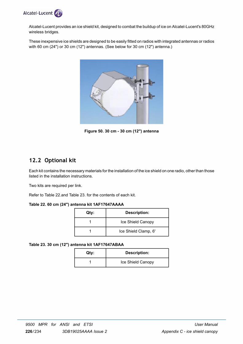
Alcatel-Lucent provides an ice shield kit, designed to combat the buildup of ice on Alcatel-Lucent's 80GHzwireless bridges.
These inexpensive ice shields are designed to be easily fitted on radios with integrated antennas or radioswith 60 cm (24") or 30 cm (12") antennas. (See below for 30 cm (12") antenna.)
Figure 50. 30 cm - 30 cm (12") antenna
12.2 Optional kit
Each kit contains the necessary materials for the installation of the ice shield on one radio, other than thoselisted in the installation instructions.
Two kits are required per link.
Refer to Table 22.and Table 23. for the contents of each kit.
Table 22. 60 cm (24") antenna kit 1AF17647AAAA
Table 23. 30 cm (12") antenna kit 1AF17647ABAA
Qty: Description:
1 Ice Shield Canopy
1 Ice Shield Clamp, 6'
Qty: Description:
1 Ice Shield Canopy
User Manual
Appendix C - ice shield canopy
9500 MPR for ANSI and ETSI
3DB19025AAAA Issue 2226/234

12.3 Installation instructions - 60 cm (24") antenna
12.3.1 Required tools
A screwdriver or 5/16" nut driver, not provided by Alcatel-Lucent, is used for installing the ice shield on60 cm (24") antennas.
12.3.2 Installation
1) Note the RSL voltage prior to installation.2) Remove the protective liner from the plastic canopy.3) Use a screwdriver or 5/16" nut driver to set the hose clamp to the end of its range for maximum
opening.4) Slip the hose clamp over the radome, so that it loosely sits approximately in the middle of the
radome.5) Slide one end of the plastic canopy under the clamp and slowly bend it around the canopy, and
work it under the rest of the clamp.6) Align the canopy to the back edge of the radome, and position the clamp 1-3" away from the
edge.7) Tighten the clamp until snug. (Do not over-tighten.).
12.4 Installation instructions - 30 cm (12") antenna
12.4.1 Required tools
The following tools, not provided by Alcatel-Lucent, are used for installing the ice shield:
– Open-end wrench 9/16-inch.
– Ratchet with 9/16-inch socket.
12.4.2 Installation
1) Note the RSL voltage prior to installation.2) Loosen the four bolts at the corners of the radio enough to slide the canopy behind the flat
washer(s) on the upper three bolts. The fourth bolt is loosened to maintain even torque on theantenna feed and to prevent the radio from fully disengaging from the antenna mount.
3) Slide the canopy into place behind the flat washers of the top three bolts.4) Evenly tighten the four bolts.
Remove the canopy when it is not snowing to reduce antenna wind load-ing.
User Manual
Appendix C - ice shield canopy
9500 MPR for ANSI and ETSI
3DB19025AAAA Issue 2 227/234

User Manual
Appendix C - ice shield canopy
9500 MPR for ANSI and ETSI
3DB19025AAAA Issue 2228/234
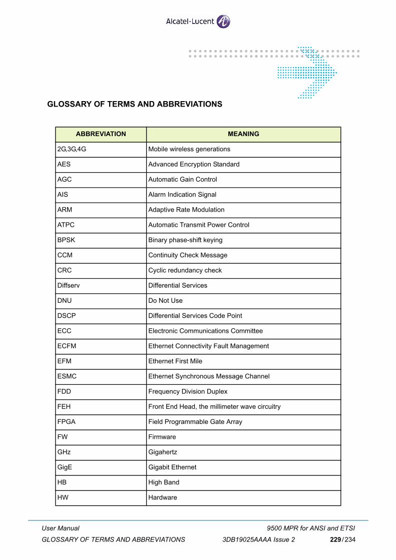
GLOSSARY OF TERMS AND ABBREVIATIONS
ABBREVIATION MEANING
2G,3G,4G Mobile wireless generations
AES Advanced Encryption Standard
AGC Automatic Gain Control
AIS Alarm Indication Signal
ARM Adaptive Rate Modulation
ATPC Automatic Transmit Power Control
BPSK Binary phase-shift keying
CCM Continuity Check Message
CRC Cyclic redundancy check
Diffserv Differential Services
DNU Do Not Use
DSCP Differential Services Code Point
ECC Electronic Communications Committee
ECFM Ethernet Connectivity Fault Management
EFM Ethernet First Mile
ESMC Ethernet Synchronous Message Channel
FDD Frequency Division Duplex
FEH Front End Head, the millimeter wave circuitry
FPGA Field Programmable Gate Array
FW Firmware
GHz Gigahertz
GigE Gigabit Ethernet
HB High Band
HW Hardware
User Manual
GLOSSARY OF TERMS AND ABBREVIATIONS
9500 MPR for ANSI and ETSI
3DB19025AAAA Issue 2 229/234

IEEE Institute of Electrical and Electronics Engineers
IFB IF Board
IP Internet Protocol
LB Low Band
LOC Loss of Carrier
LOS Loss of Signal
LSP Link State Propagation
LTE Long Term Evolution
MA Maintenance Association
MAC Media Access Control
Mbps Mega Bits Per Second
MD Maintenance Domain
MEP Maintenance End Point
MHz Megahertz
MIP Maintenance Intermediate Point
mm-wave Millimeter wave
MP Maintenance Point
OAM Operation Administration Maintenance
OC-12 Synchronous data network line rate of 622.080 Mbps
OC-3 Synchronous data network line rate of 155.520 Mbps
ODU Outdoor Unit
Pbits Priority bits
PDU Protocol data unit
PRBS Pseudo random bit sequence
QoS Quality of Service
QPSK Quadrature phase-shift keying
RADIUS Remote Authentication Dial In User Service
RF Radio Frequency (normally the highest frequencies in the product)
RMA Return Material Authorization
RoHS Restrictions of Hazardous Materials
ABBREVIATION MEANING
User Manual
GLOSSARY OF TERMS AND ABBREVIATIONS
9500 MPR for ANSI and ETSI
3DB19025AAAA Issue 2230/234
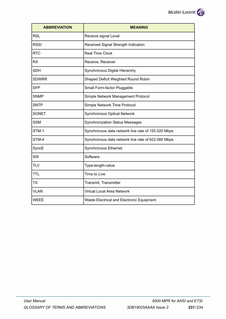
RSL Receive signal Level
RSSI Received Signal Strength Indication
RTC Real Time Clock
RX Receive, Receiver
SDH Synchronous Digital Hierarchy
SDWRR Shaped Deficit Weighted Round Robin
SFP Small Form-factor Pluggable
SNMP Simple Network Management Protocol
SNTP Simple Network Time Protocol
SONET Synchronous Optical Network
SSM Synchronization Status Messages
STM-1 Synchronous data network line rate of 155.520 Mbps
STM-4 Synchronous data network line rate of 622.080 Mbps
SyncE Synchronous Ethernet
SW Software
TLV Type-length-value
TTL Time to Live
TX Transmit, Transmitter
VLAN Virtual Local Area Network
WEEE Waste Electrical and Electronic Equipment
ABBREVIATION MEANING
User Manual
GLOSSARY OF TERMS AND ABBREVIATIONS
9500 MPR for ANSI and ETSI
3DB19025AAAA Issue 2 231/234

User Manual
GLOSSARY OF TERMS AND ABBREVIATIONS
9500 MPR for ANSI and ETSI
3DB19025AAAA Issue 2232/234

CUSTOMER DOCUMENTATION FEEDBACK
Customer documentation
http://www.alcatel-lucent.com/myaccess
Product manuals and documentation updates are available at alcatel-lucent.com. If you are a newuser and require access to this service, contact your Alcatel-Lucent sales representative.
Technical support
http://support.alcatel-lucent.com
Documentation feedback
User Manual
Customer Documentation Feedback
9500 MPR for ANSI and ETSI
3DB19025AAAA Issue 2 233/234

234
User ManualCustomer Documentation Feedback
9500 MPR for ANSI and ETSI
3DB19025AAAA Issue 2234/234

3DB19025AAAA Edition 2

w
All rights reserved.Passing on and copying of this document,
use and communication of its contents is not permittedwithout written authorization from Alcatel -Lucent.
ww.alcatel-lucent.com