Embed Size (px)
Citation preview

Owner's Manual - July, 1994 -
WARNING: If the information in this manual is not followed exactly, a fire or explosion mayresult causing property damage, personal injury or loss of life.
- Do not store or use gasoline or other flammable vapors and liquids in the vicinity of this or anyother appliance.
- WHAT TO DO IF YOU SMELL GAS¥ Do not try to light any appliance.¥ Do not touch any electrical switch; do not use any phone in your building.¥ Immediately call gas supplier from a neighbor's phone. Follow the gas supplier's instructions.¥ If you cannot reach your gas supplier, call the fire department.
- Installation and service must be performed by a qualified installer, service agency or the gas supplier.
Spirit - Gas Stove Room Heater10850 117th Place N.E. Kirkland, WA 98033
OMNI Listed

PAGE 2 SAFETY PRECAUTIONS
¥ IF YOU SMELL GAS:
* Do not light any appliance* Extinguish any open flame* Do not touch any electrical switch or plug or unplug anything* Open windows and vacate building* Call gas supplier from neighbor's house, if not reached, call fire department
¥ This unit must be installed by a qualified installer to prevent the possibility ofan explosion. Your dealer will know the requirements in your area and caninform you of those people considered qualified. The room heater should beinspected before use and at least annually by a qualified service person. Morefrequent cleaning may be required due to excessive lint from carpeting,bedding material, etc.
¥ The instructions in this manual must be strictly adhered to. Do not usemakeshift methods or compromise in the installation. Improper installationwill void the warranty and safety listing.
THIS CONTROL HAS BEEN
CONVERTED FOR NATURAL GAS
THIS CONTROL
HAS BEEN CONVERTED TO
LP
¥ This heater is either approved for natural gas(NG) or for propane (LP). Burning theincorrect fuel will void the warranty and safetylisting and may cause an extreme safetyhazard. Direct questions about the type of fuelused to your dealer. Check the label and flameadjust knob on the gas control valve.
OOkk
¥ Contact your localbuilding officials toobtain a permit andinformation on anyinstallation restrictions orinspection requirements inyour area. Notify yourinsurance company of thisheater as well.
¥ If the flame becomessooty, dark orange incolor, or extremely tall,do not operate the heater.Call your dealer andarrange for properservicing.
¥ It is imperative thatcontrol compartments,screens, or circulating airpassageways of the heaterbe kept clean and free ofobstructions. These areasprovide the air necessaryfor safe operation.
?¥ Do not operate the heater
if it is not operatingproperly in any fashion orif you are uncertain. Callyour dealer for a fullexplanation of your heaterand what to expect.
Gas
¥ Do not store or usegasoline or otherflammable liquids in thevicinity of this heater.
¥ Keep all furniture or othercombustible items at least36" away from the frontof the heater.
¥ Do not operate if anyportion of the heater wassubmerged in water or ifany corrosion occurs.

SAFETY PRECAUTIONS (CONTINUED) PAGE 3
¥ Do not place clothing orother flammable items onor near the heater.Because this heater can becontrolled by a thermostatthere is a possibility of theheater turning on andigniting any items placedon or near it.
AAAAAAAAA
¥ Light the heater using thebuilt-in piezo igniter. Donot use matches or anyother external device tolight your heater.
¥ Never remove, replace,modify or substitute anypart of the heater unless
¥ The viewing glass shouldbe opened for service only(see the maintenancesection of this manual).
¥ Any safety screen orguard removed forservicing must bereplaced prior tooperating the heater.
instructions are given inthis manual. All otherwork must be done by atrained technician. Don'tmodify or replace orifices.
¥ Allow the heater to coolbefore carrying out anymaintenance or cleaning.
¥ Operate the heateraccording to theinstructions included inthis manual.
¥ If the main burners do notstart correctly turn the gasoff at the gas controlvalve and call your dealerfor service.
¥ The pilot flame mustcontact the thermopileand thermocouple (see theillustration to the left). Ifit does not, turn the gascontrol valve to "OFF"and call your dealer.
¥ This unit is not for usewith solid fuel
¥ Do not place anythinginside the firebox (exceptthe included fiber logs).
¥ If the fiber logs becomedamaged, replace withTravis Industries log set.
ThisManual
¥ Do not throw this manualaway. This manual hasimportant operating andmaintenance instructionsthat you will need at alater time. Always followthe instructions in thismanual.
¥ Do not touch the hotsurfaces of the heater.Educate all children of thedanger of a high-temperature heater.Young children should besupervised when they arein the same room as theheater.
¥ Plug the heater into a115V grounded electricaloutlet. Do not remove thegrounding plug.
¥ Don't route the electricalcord in front of or overthe heater
¥ Instruct everyone in thehouse how to shut gas offto the appliance and at thegas main shutoff valve.The gas main shutoffvalve is usually next tothe gas meter or propanetank and requires awrench to shut off.
¥ Travis Industries, Inc.grants no warranty,implied or stated, for theinstallation ormaintenance of yourheater, and assumes noresponsibility of anyconsequentialdamage(s).

PAGE 4 TABLE OF CONTENTS
General InformationIntroduction & Important Information ................................................................................................... 1Safety Precautions............................................................................................................................... 2Features & Specifications.................................................................................................................... 5
Stove InstallationHeater Placement ................................................................................................................................ 6Floor Protection ................................................................................................................................... 7Vent Requirements.............................................................................................................................. 7Gas Line Install .................................................................................................................................... 8Finalizing the Installation ..................................................................................................................... 9
Operating Your HeaterReviewing the Installation.................................................................................................................... 10Before You Begin................................................................................................................................. 11Location of Controls ............................................................................................................................. 11Starting The Pilot ................................................................................................................................. 12Running Your Heater ........................................................................................................................... 13
Starting the Heater for the First Time ........................................................................................... 13Turning the Heater On and Off ..................................................................................................... 14Adjusting the Flame Height .......................................................................................................... 15Adjusting the Blower Speed ......................................................................................................... 15
Normal Operating Sounds ................................................................................................................... 15
Maintaining Your HeaterInspecting the Firebox ......................................................................................................................... 16Installing and Removing the Logs and Coals ...................................................................................... 17Inspecting the Door ............................................................................................................................. 18
Replacing the Door Gasket .......................................................................................................... 18Replacing the Glass or Glass Gasket........................................................................................... 18
TroubleshootingTroubleshooting Table ......................................................................................................................... 19How this Heater Works........................................................................................................................ 20
What Turns the Main Burners On and Off .................................................................................... 20Why Nothing Should Be Placed Against the Heater..................................................................... 20What Prevents Gas Buildup ......................................................................................................... 21Wiring Diagram............................................................................................................................. 22Replacement Parts List ................................................................................................................ 22
WarrantyWarranty .............................................................................................................................................. 23
Listing InformationListing Information ............................................................................................................................... 24
Optional EquipmentLegs ..................................................................................................................................................... 25Pedestal ............................................................................................................................................... 25Remote Control ................................................................................................................................... 26Thermostat........................................................................................................................................... 28Re-Routing the Power Cord to the Left or Rear of the Heater............................................................. 30
IndexIndex.................................................................................................................................................... 32

FEATURES AND SPECIFICATIONS PAGE 5
Features:
¥ Works During Power Outages (utilizes millivolt system)
¥ High Efficiency; up to 80% for Natural Gas, 82% for LP (Steady State)
¥ Optional Thermostat or Remote Control
¥ Realistic "Wood Fire" Look
¥ Convenient Operating Controls
¥ Variable-Rate Heat Output
¥ Quiet Blower for Effective Heat Distribution¥ Low Maintenance
Heating Specifications: Spirit NaturalGas
Spirit LP(propane)
Approximate Maximum Heating Capacity (in square feet)* 900 - 1,500 900 - 1,500High Burn Input Rate (In BTU's)** 31,000 31,000Low Burn Input Rate (In BTU's)** 18,000 17,000AFUE Efficiency 70.0% 70.0%
* Heating capacity will vary depending on the home's floor plan, degree of insulation, and the outside temperature. It is alsoaffected by the natural gas or LP BTU rating.
** To measure the net BTU's, multiply the BTU input by the efficiency percentage (80% for natural gas, 82% for LP).
Spirit Dimensions
HEIGHT*:With Pedestal 34 7/8" **With Brass Legs 30 7/8"With Cast Legs 30 7/8"With Black Legs 29 1/2"
* Subtract 4" to reach the base of the flue collar**Use the Lopi pedestal, part # 99200 101
20 3/4" 24"5 1/2"
Vent Opening Diameter = 4"Weight = 205 Pounds
Electrical Specifications:Blower Electrical Rating: 115 Volts, 1.3 Amps, 60 Hz (150 watts on high)
Fuel:The heater is designed either for natural gas or for propane (but not for both). Check the stickeron the top of the gas control valve.
Emissions:This unit has passed the ANSI emission standards for vented room heaters as tested by WarnockHersey, LTD.
PAGE 6 STOVE INSTALLATION - For qualified installers only!
This appliance must be installed in accordance with all local codes, if any; if not,follow ANSI Z223.1 and the requirements listed in this manual. Failure to follow allof the requirements may result in property damage, bodily injury, or even death.
Check with local building officials for any permits required for installation of this gas heater andnotify your insurance company before hooking up this heater. The requirements listed below aredivided into sections. All requirements must be met simultaneously. The order of installation isnot rigid Ð the qualified installer should follow the procedure best suited for the installation.
Heater PlacementThe heater must be placed so the following requirements are met:
¥ Stove must be placed so that no combustibles are within, or can swing within (e.g.drapes, doors), 36" of the front of the heater
¥ The stove must be placed on a set of Travis Industries legs or pedestal¥ Heater must be installed on a level, secure floor¥ The stove must not be placed so the vents below the ashlip, above the door, along
the sides of stove, or along the back of the heater can become blocked
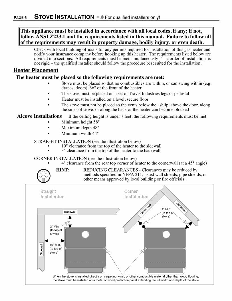
Alcove Installations If the ceiling height is under 7 feet, the following requirements must be met:¥ Minimum height 58"¥ Maximum depth 48"¥ Minimum width 44"
STRAIGHT INSTALLATION (see the illustration below)¥ 10" clearance from the top of the heater to the sidewall¥ 3" clearance from the top of the heater to the backwall
CORNER INSTALLATION (see the illustration below)¥ 4" clearance from the rear top corner of heater to the cornerwall (at a 45° angle)
HINT: REDUCING CLEARANCES - Clearances may be reduced bymethods specified in NFPA 211, listed wall shields, pipe shields, orother means approved by local building or fire officials.
Corner Insta l lat ion
Backwall
Sid
ewal
l
Straight Insta l lat ion
CornerwallCor
nerw
all
4" MIn.(to top of stove)
10" MIn.(to top of stove)
3" MIn.(to top of stove)
When the stove is installed directly on carpeting, vinyl, or other combustible material other than wood flooring, the stove must be installed on a metal or wood protection panel extending the full width and depth of the stove.

STOVE INSTALLATION (CONT.) - For qualified installers only! PAGE 7
Floor ProtectionWhen the stove is installed directly on carpeting, vinyl or other combustible material other thanwood flooring, the stove must be installed on a metal or wood protection panel extending the fullwidth and depth of the stove.
Vent RequirementsThe vent must be installed in accordance with all local codes, if any; if not, follow ANSI 223.1and the requirements listed below. Furthermore, the vent must be installed to meet theinstallation requirements of the vent manufacturer.
¥ Minimum 5' vertical rise from top of stove (see the illustration below)¥ The horizontal run may not exceed 50% of the vertical rise¥ Use 4" dia. B vent for entire system from one manufacturer (don't mix brands)
- or -Use high temperature factory built chimney and connector with listed gaschimney liner running the entire length
¥ The vent must not service another appliance¥ 1" clearance to all combustibles must be maintained¥ Must meet all of the vent manufacturer's requirements¥ Vent termination must be above the roof and not below any eaves or overhangs
Type B Vent
Vent must terminate a minimum 1' above the roof.
Listed Gas Chimney Liner
Maintain 1" minimum clearance
Provide a 1/4" rise for every 12" run.
Min. 5' RiseHigh temperature factory built chimney and connector
Chimney with LinerStandard Installation Exterior Vent
Min. 5' Rise
The total horizontal run must not exceed 50% of the vertical rise
Do not block gas vent termination

PAGE 8 STOVE INSTALLATION (CONT.) - For qualified installers only!
Vent Requirements (continued)
¥ Vent termination must have an approved cap (to prevent water from entering)¥ Vent termination must not be located where it will become plugged by snow or
other material¥ Vent termination must be 1' above the roof and meet the requirements outlined in
ANSI 223.1, section 7.6.2.
1' Minimum
Note: ANSI 223.1, section 7.6.2 outlines additional requirements for gas vent terminations. If your installation involves a roof with a slope greater than 6/12 or if a wall or other verical obstruction is within 8' of the vent termination, the vent termination will need to be taller. Refer to ANSI 223.1 for full details.
NOTE: When installed, the vent must provide suitable draft for theappliance. Other factors, such as exhaust fans, may create negativepressure inside the home and cause down drafts. Additional ventheight may be required in these circumstances.
Draft Hood
TO TEST THE DRAFT:Remove the back panel. Start the heater and check the perimeter of the draft hood with a gas detector or smoke. If combustion products leak out the draft hood, the vent may need to be taller to improve draft.
Vent Collar
Spill Switch
Gas Line InstallThe gas line must be installed in accordance with all local codes, if any; if not, follow ANSI223.1 and the requirements listed below.
Gas Line Connection:
¥ The gas inlet is a male 3/8" NPT¥ This appliance requires a shutoff valve upstream of
the appliance. This valve must be accessible andwithin 3 feet of the heater.

STOVE INSTALLATION (CONT.) - For qualified installers only! PAGE 9
Gas Inlet Location:
The 3/8" N.P.T. gas inlet portrudes 1 1/2" from the back edge of the stove.
HEIGHT: From Base of Stove 1 1/2"With Pedestal 12 3/4"With Brass Legs 9 3/8"With Cast Legs 9 3/8"With Black Legs 8"
LOCATION OF THE GAS INLET CENTER:
CL
7 1/2" (from center of stove)
Gas Pressure:Minimum Input Pressure
Natural Gas 7" W.C.Propane 11" W.C.
¥ If the pressure is not sufficient, make sure the piping used is large enough, thesupply regulator is adequately adjusted, and the total gas load for the residencedoes not exceed the amount supplied.
¥ The supply regulator (the regulator that attaches directly to the residence inlet orto the propane tank) should supply gas at the suggested input pressure listedabove. Contact the local gas supplier if the regulator is at an improper pressure.
Purging the Gas Line:The gas line must be properly purged to release all air in the gas line prior to starting the heater.
Finalizing the Installation¥ Before starting, all gas line joints must be leak tested.¥ Optional equipment must be installed (instructions are in the rear of this manual).¥ The ceramic logs must be placed inside the firebox (see the section "Installing the
Logs and Coals" in the maintenance section of this manual).¥ Start the heater and check for proper performance. Review the operations portion
of this manual to make sure the owner understands the operation of the heater.Note: See the instructions "Re-Routing the Power Cord to the Left or Rear of the Heater" in the optional
equipment section of this manual to re-route the power cord.

PAGE 10 REVIEWING THE INSTALLATION
The check off list below details the installation concerns that you, the consumer,should know prior to starting the heater. This information is very important andmust be checked off.
( ) There are no combustibleitems placed within 36" of thefront of the heater or swingwithin 36" of the front ofheater. This includesfurniture, doors, drapes, etc.
Combustible
36" Minimum
( ) No combustibles are within1" of the exhaust vent. Duetoo high temperatures, theroom heater should be locatedout of traffic and away fromcombustibles. This includesdrywall, drapes, window sills,etc. If any question exists,call your dealer for a fullexplanation.
CombustibleGas Vent
Min.1" clearance
( ) The location of the GASMAIN SHUTOFF VALVE.It is usually directly next tothe gas meter or propane tankand may require a wrench toshut off. Everyone in thehouse should know where thegas main shutoff valve is andhow to turn it off.
On most valves this is ON On most valves this is OFF
( ) All of the necessary permitsand installation informationhave been obtained for yourrecords. This includes thepermits from buildingofficials, receipts, and thismanual.
O k
Permits Receipts This Manual
OWNER'SMANUAL
( ) The operation card includedwith the heater slides outfrom behind the access panel.If you can not find it, callyour dealer for details. Thiscard includes importantoperation information thatmust be kept with the heaterat all times.

OPERATING YOUR HEATER PAGE 11
Before You BeginREAD THIS ENTIRE MANUAL BEFORE YOU USE YOUR NEW HEATER.FAILURE TO FOLLOW THE INSTRUCTIONS MAY RESULT IN PROPERTYDAMAGE, BODILY INJURY, OR EVEN DEATH.
Before starting your heater make sure you have read the section titled Safety Precautions. Anyquestions should be referred to your dealer.
Location of Controls - See explanation below
Flame Adjust Knob
With the access panel flipped down the controls can be accessed.
ON
OFF
MA
IN
BU
RN
ER
PILOT IGNITER
BL
OW
ER
Gas Control Knob
ON/OFF Switch
PILOT IGNITER
BLOWER Dial
H IOFF
LO
Blower Knob This knob controls the speed of the internal convection blower that pushes theheated air into the room.
On/Off Switch This control is used to turn the heater on and off.
Pilot Igniter The pilot igniter is used only to start the pilot. When pressed, it sends anelectrical charge to the pilot assembly. This creates a blue spark directly nextto the pilot, igniting the pilot flame.
Gas Control Knob This knob is used to control gas to the heater and for starting the pilot. Thereare three positions, ON, OFF, & PILOT. The pointer directly below the knobindicates the position this knob is in.
Flame Adjust Knob This knob controls the flame height from low ("LO") to high ("HI"). Thepointer to the upper right of the knob points to the position this knob is in.
? If using a remote control or thermostat, the On/Off Switch must be left "ON".Turning the On/Off Switch "OFF" will keep the heater off always.

PAGE 12 OPERATING YOUR HEATER (CONTINUED)
Starting The Pilot FlameThe pilot flame is required to ignite the main burners (it also plays a safety role). It should beleft on once lit. It will stay lit unless the gas control valve is turned to "OFF". However, thepilot will go out if the gas is shut off or if the heater malfunctions. If the pilot turns offfrequently, call your dealer for information. To start the pilot follow the directions below:
A Push the gas controlknob in slightly and turnit to the "OFF" position.The knob will not turnfrom "ON" to "OFF"unless the knob isdepressed slightly.
B Wait five minutes to letany gas that may haveaccumulated inside thefirebox escape. If yousmell gas, follow thedirections on the cover"IF YOU SMELL GAS".
C Turn the gas controlknob to the "PILOT"position and press theknob in, this will allowgas to flow to the pilotlight. Press the redbutton on the pilotigniter repeatedly untilyou see the pilot light.KEEP THE GASCONTROL KNOBDEPRESSED FOR 30SECONDS ONCE IT ISLIT. Note: If the pilotdoes not light afterseveral tries, call yourdealer for service.
D Release the gas controlknob. If the pilot goesout, repeat step C. If thepilot refuses to stay lit,call your dealer forservice.
E Turn the gas controlknob counter-clockwiseto "ON". The pilot isnow lit and the heatercan be turned on and off.
PILOT ADJ
PILOT ADJ
PILOT IGNITER
T OL PI
ONOFF
PILOT ADJ
T OL PI
ONOFF
AAAAAA
AAAA
30 seconds
AAAAAAAA
AAAA
5 minutes
TO
L
PI
ON
OF
F
PILOT ADJ
T OL PI
ONOFF
?
A B
C
D
PILOT ADJ
E
TO
L
PI
ON
OF
F
PILOT SPARK

OPERATING YOUR HEATER (CONTINUED) PAGE 13
Starting the Heater for the First Time¥ Paint Curing insures a durable finish. Start the heater and burn on low for 20
minutes. Turn off and let cool. Repeat twice to fully cure the paint.+ Fumes and smoke from the paint curing and oil burning off the steel may occur
the first time you start your heater. This is normal. We recommend you openwindows to vent the room.
+ Condensation may appear on the glass each time you start the heater - this isnormal.
+ Blue Flames will occur on the heater when it first comes on. After fifteenminutes the flames will turn a more realistic yellow and orange color.
? Certain installations use a remote "wall switch" to turn the heater on and off. Ifthis is the case, leave the ON/OFF switch "ON".
Turning the Heater On and Off
OFF
ON
Use this switch to turn the main burner on and off manually.
After the pilot has been started...
For systems with remotes, make sure the On/Off Switch shown to the left is on. Then use this button here to turn the main burner on and off.
For systems with thermostats, use this switch to control the temperature (right is hotter, left cooler). Some systems require the on/off switch to be on.
See the optional equipment instructions for installing the battery.
! Do not place any combustible items on top of or directly in front of the heater,even temporarily. The optional thermostat may start the heater causing acombustible item to ignite.
? If the heater turns on and off frequently while using the thermostat, you may wantto adjust the flame height down until it produces just enough heat needed.
Adjusting the Flame Height+ Your heater has an adjustable flame to tailor the look and heat output to your
specific needs. It is adjusted by turning the middle dial on the gas control valve.
Flame Height Adjustment Knob
Index Mark
Turn clockwise to adjust the flame higher, counter-clockwise to lower.
PILOT ADJ
VE
NT
TO L PI
ON
OFF
HILO
VE
NT
HI
LO

PAGE 14 OPERATING YOUR HEATER (CONTINUED)
Adjusting the Blower Speed+ The blower helps transfer the heat from the heater into the room. It will not turn
on until the heater is up to temperature (approximately 10 minutes after starting).See the illustration below for instructions on adjusting the blower speed.
BL
OW
ER
LO
OFF HIPILOT IGNITER
Blower Knob
Turn the knob all the way counter-clockwise to turn the blower off. One click clockwise turns the blower to high speed. Turning the knob clockwise from the high position decreases the speed of the blower.

OPERATING YOUR HEATER (CONTINUED) PAGE 15
Normal Operating Sounds
Gas Control ValveAs the gas control valve is turned on and off you will hear a dull clicking sound. This is the valve opening up and shutting down.
Blower This heater uses a high tech blower to push heated air into the room. It will make a whirring sound and will increase in volume as the speed is increased.
Burner PanThe burner pan is underneath the logs and is used to mix the proper amount of air with the natural gas to produce a clean and efficient burn. When it is started you will hear a slight "whoosh" sound. When the main burner is running you will hear the gas flowing through the burner pan and orifices Ð this sound will decrease as the flame height is lowered.
Pilot FlameThe pilot flame, which remains on, makes a very slight "whisper" sound.
Blower Thermodisk This part can produce a clicking sound as it turns the blower on and off.
Stove BodyDue to the heavy steel construction, occasional clicks may come from the heater, especially during startup.

PAGE 16 MAINTAINING YOUR HEATER
Every year you should inspect the firebox and door to make sure they are clean and functional.
WARNING: Failure to inspect and maintain your heater may lead to improperburning inside the heater, leading to a dangerous situation.
Inspecting the FireboxThe firebox should be inspected and cleaned of any soot or dust that may have been drawn intothe heater. To do this, follow the directions below.
1. Remove the door (see the illustration below).
Lift the door off the hinges (use both hands).
1. Unscrew the handle until it can be removed.
2. Swing the door open.
3.
2. Remove the logs and coals (see the instructions on the following page).3. Use a vacuum cleaner with a soft brush attachment to vacuum any dirt off the
burner pan (see the illustration below). The rear log is fragile and should not bevacuumed. Inspect the burner pan and firebox for any deterioration. If it showssigns of deterioration, call your dealer for a full inspection. There should be nosoot in the firebox, except for a small amount on the logs where the flames brushup against them. If there is additional soot, the heater may need adjustment.Contact your dealer for information.
Make sure all the burner holes are clean and no dirt has collected Log clips
Rear log
4. To replace the front log and coals follow the directions in the section "Installingthe Logs and Coals".
5. Replace the door. Turn the door handle clockwise until the door seals tight withdoor handle facing downward.
MAINTAINING YOUR HEATER (CONTINUED) PAGE 17
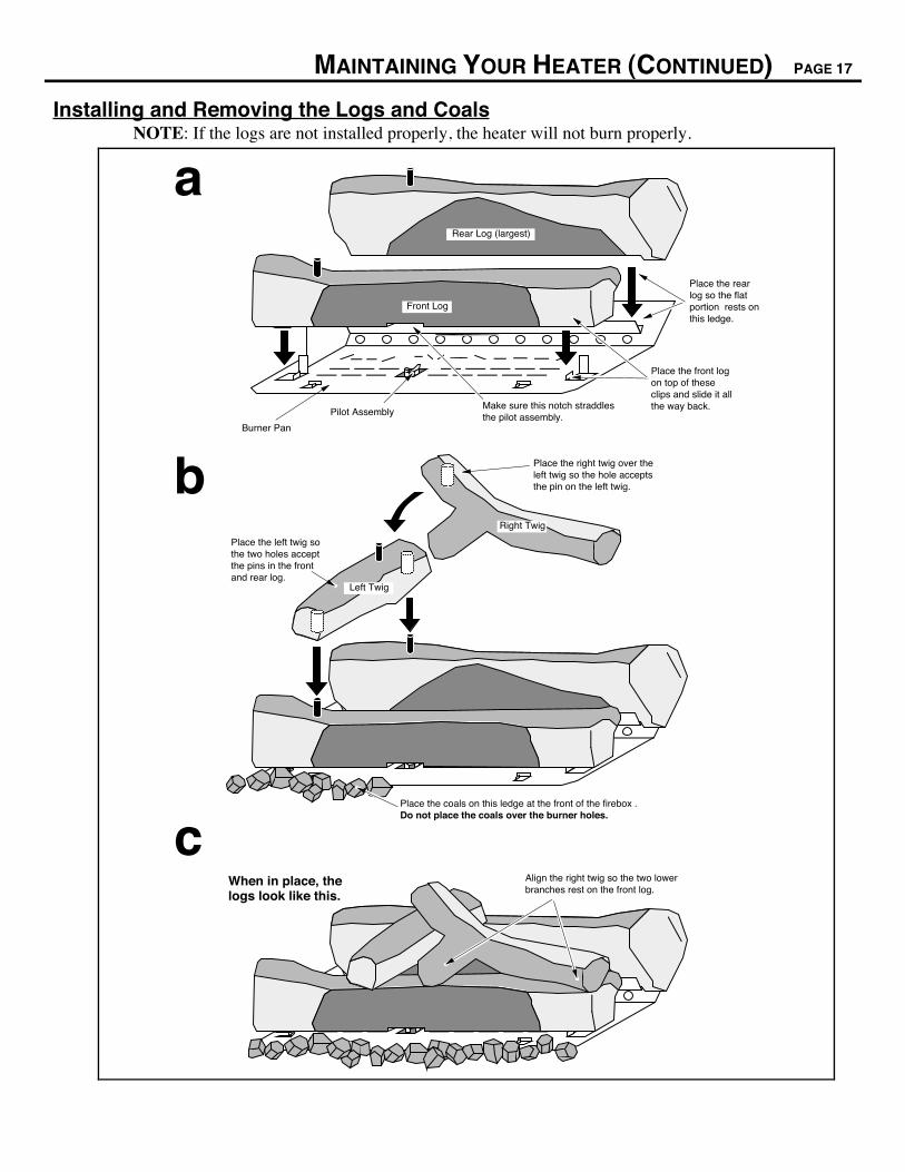
Installing and Removing the Logs and CoalsNOTE: If the logs are not installed properly, the heater will not burn properly.
Place the left twig so the two holes accept the pins in the front and rear log.
AAAAAAAAA
AAAAA
Left Twig
Place the right twig over the left twig so the hole accepts the pin on the left twig.
Place the coals on this ledge at the front of the firebox . Do not place the coals over the burner holes.
AAAAA
Right Twig
Place the rear log so the flat portion rests onthis ledge.
Rear Log (largest)
Place the front log on top of these clips and slide it all the way back.
Pilot Assembly
Front Log
Burner Pan
When in place, the logs look like this.
Align the right twig so the two lower branches rest on the front log.
a
b
c
Make sure this notch straddles the pilot assembly.
PAGE 18 MAINTAINING YOUR HEATER (CONTINUED)
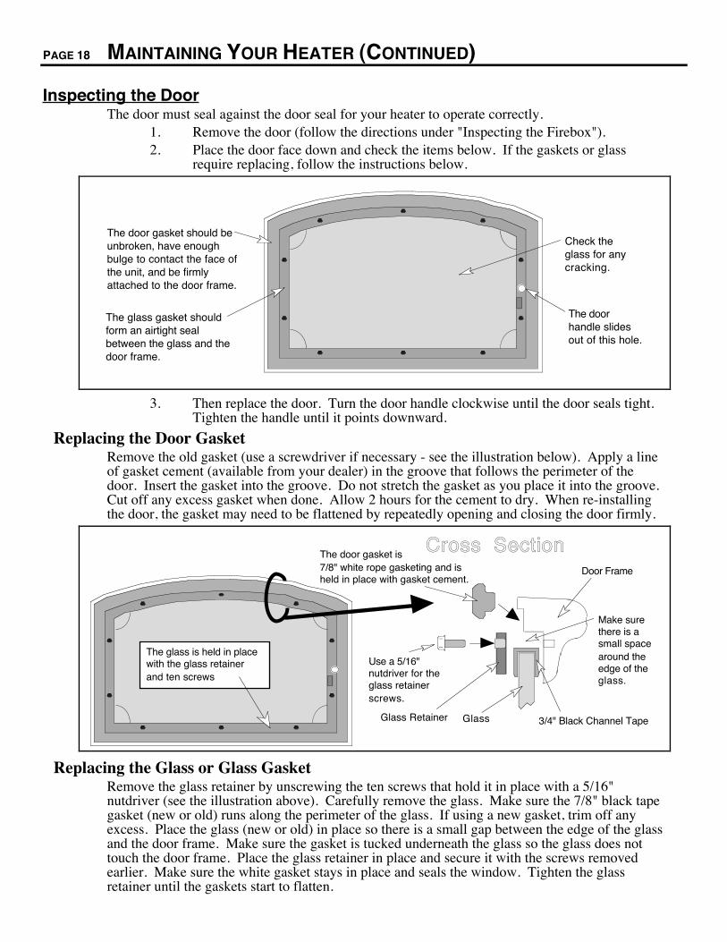
Inspecting the DoorThe door must seal against the door seal for your heater to operate correctly.
1. Remove the door (follow the directions under "Inspecting the Firebox").2. Place the door face down and check the items below. If the gaskets or glass
require replacing, follow the instructions below.
The door gasket should be unbroken, have enough bulge to contact the face of the unit, and be firmly attached to the door frame.
The glass gasket should form an airtight seal between the glass and the door frame.
Check the glass for any cracking.
The door handle slides out of this hole.
3. Then replace the door. Turn the door handle clockwise until the door seals tight.Tighten the handle until it points downward.
Replacing the Door GasketRemove the old gasket (use a screwdriver if necessary - see the illustration below). Apply a lineof gasket cement (available from your dealer) in the groove that follows the perimeter of thedoor. Insert the gasket into the groove. Do not stretch the gasket as you place it into the groove.Cut off any excess gasket when done. Allow 2 hours for the cement to dry. When re-installingthe door, the gasket may need to be flattened by repeatedly opening and closing the door firmly.
Use a 5/16" nutdriver for the glass retainer screws.
The door gasket is 7/8" white rope gasketing and is held in place with gasket cement.
Cross SectionDoor Frame
GlassGlass Retainer 3/4" Black Channel Tape
The glass is held in place with the glass retainer and ten screws
Make sure there is a small space around the edge of the glass.
Replacing the Glass or Glass GasketRemove the glass retainer by unscrewing the ten screws that hold it in place with a 5/16"nutdriver (see the illustration above). Carefully remove the glass. Make sure the 7/8" black tapegasket (new or old) runs along the perimeter of the glass. If using a new gasket, trim off anyexcess. Place the glass (new or old) in place so there is a small gap between the edge of the glassand the door frame. Make sure the gasket is tucked underneath the glass so the glass does nottouch the door frame. Place the glass retainer in place and secure it with the screws removedearlier. Make sure the white gasket stays in place and seals the window. Tighten the glassretainer until the gaskets start to flatten.

TROUBLESHOOTING PAGE 19
Problem: Possible Cause: Don't Call for ServiceUntil You:
Pilot Will Not Light A gas shut off valve is turned off
The valve control knob isn't turned to "PILOT"
The valve control knob isn't pushed in
The igniter wasn't pressed repeatedly
Check all gas shut off valves
See "Starting the Pilot Light" Step C
See "Starting the Pilot Light" Step C
See "Starting the Pilot Light" Step C
Main Burners Will NotStart
The pilot light has gone out
The ON/OFF switch is turned to "OFF"
The remote control is not working correctly
The thermostat is disconnected or set too high
See "Starting the Pilot Light"
Turn the ON/OFF switch to "ON"
See "Remote Control Operation"
See "Thermostat Operation"
Remote Control DoesNot Work
The pilot light has gone out
The ON/OFF switch is turned to "OFF"
The remote is too far away from the heater
The remote control receiver is turned "Off" or "On"
One of the two remote control batteries is dead
See "Starting the Pilot Light"
Turn the ON/OFF switch to "ON"
Use the remote closer to the heater
See "Remote Control Operation"
See "Remote Control Operation"
Thermostat Does NotWork
The pilot light has gone out
The ON/OFF switch is turned to "OFF"
The thermostat is set too high
See "Starting the Pilot Light"
Turn the ON/OFF switch to "ON"
See "Thermostat Operation"
Heater Will NotDistribute Heat
The heater is unplugged
The heater is not up to temperature
Plug the heater in.
See "Operating Your Heater"
Pilot Goes Out Once AMonth Or More
The gas supply has not been shut off
The vent is experiencing a cold air blockage or a negativepressure situation exists in the home
Keep the gas supply turned on
This is a necessary safety feature thatdisables the heater if a down draft occurs.If this problem is persistent the vent mayneed to be improved or changes may needto be done to remove the negative pressureinside the home - see your dealer fordetails
Flame (and Pilot) GoesOut 10 to 25Minutes AfterStarting
The vent is experiencing a cold air blockage or a negativepressure situation exists in the home
This is a necessary safety feature. First tryrestarting the heater. If it works correctly,a cold air blockage occurred and the ventjust needed to be heated sufficiently. Ifthis problem is persistent the vent mayneed to be improved or changes may needto be done to remove the negative pressureinside the home - see your dealer fordetails
Flames Are Too Blue The heater has just been started This is normal - see "Operating YourHeater"
Flames Are OrangeWith Dirty Smoke
Something may be placed against the heater See "How this Heater Works"
Flames Are Too Short(Under 6")
The flame height may be turned too low
Something may be placed against the heater
Turn the flame height to "HI" -See "Operating Your Heater"
See "How this Heater Works"
Thin Layer of SootCovers the Glass
The logs are placed incorrectly See "Installing the Logs and Coals"
PAGE 20 TROUBLESHOOTING (CONTINUED)
How this Heater WorksThis gas heater is designed with safety as the primary concern. Most of the components insidethis heater are used for safety purposes. Therefore, only certified gas service technicians shouldservice this heater. Your dealer can help you find a certified gas service technician.
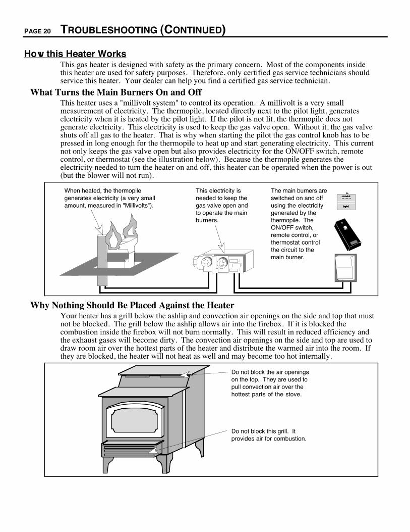
What Turns the Main Burners On and OffThis heater uses a "millivolt system" to control its operation. A millivolt is a very smallmeasurement of electricity. The thermopile, located directly next to the pilot light, generateselectricity when it is heated by the pilot light. If the pilot is not lit, the thermopile does notgenerate electricity. This electricity is used to keep the gas valve open. Without it, the gas valveshuts off all gas to the heater. That is why when starting the pilot the gas control knob has to bepressed in long enough for the thermopile to heat up and start generating electricity. This currentnot only keeps the gas valve open but also provides electricity for the ON/OFF switch, remotecontrol, or thermostat (see the illustration below). Because the thermopile generates theelectricity needed to turn the heater on and off, this heater can be operated when the power is out(but the blower will not run).
When heated, the thermopile generates electricity (a very small amount, measured in "Millivolts").
This electricity is needed to keep the gas valve open and to operate the main burners.
The main burners are switched on and off using the electricity generated by the thermopile. The ON/OFF switch, remote control, or thermostat control the circuit to the main burner.
Why Nothing Should Be Placed Against the HeaterYour heater has a grill below the ashlip and convection air openings on the side and top that mustnot be blocked. The grill below the ashlip allows air into the firebox. If it is blocked thecombustion inside the firebox will not burn normally. This will result in reduced efficiency andthe exhaust gases will become dirty. The convection air openings on the side and top are used todraw room air over the hottest parts of the heater and distribute the warmed air into the room. Ifthey are blocked, the heater will not heat as well and may become too hot internally.
Do not block this grill. It provides air for combustion.
Do not block the air openings on the top. They are used to pull convection air over the hottest parts of the stove.
TROUBLESHOOTING (CONTINUED) PAGE 21
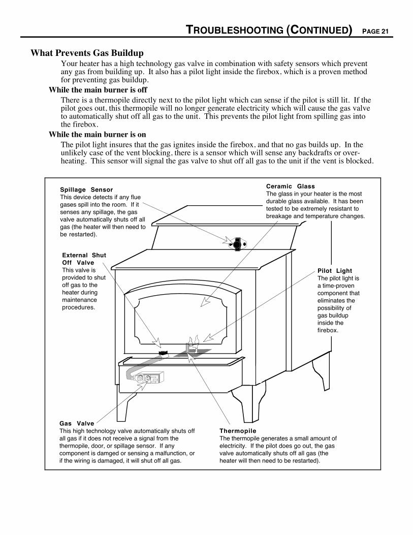
What Prevents Gas BuildupYour heater has a high technology gas valve in combination with safety sensors which preventany gas from building up. It also has a pilot light inside the firebox, which is a proven methodfor preventing gas buildup.
While the main burner is offThere is a thermopile directly next to the pilot light which can sense if the pilot is still lit. If thepilot goes out, this thermopile will no longer generate electricity which will cause the gas valveto automatically shut off all gas to the unit. This prevents the pilot light from spilling gas intothe firebox.
While the main burner is onThe pilot light insures that the gas ignites inside the firebox, and that no gas builds up. In theunlikely case of the vent blocking, there is a sensor which will sense any backdrafts or over-heating. This sensor will signal the gas valve to shut off all gas to the unit if the vent is blocked.
Spillage SensorThis device detects if any flue gases spill into the room. If it senses any spillage, the gas valve automatically shuts off all gas (the heater will then need to be restarted).
Gas ValveThis high technology valve automatically shuts off all gas if it does not receive a signal from the thermopile, door, or spillage sensor. If any component is damged or sensing a malfunction, or if the wiring is damaged, it will shut off all gas.
ThermopileThe thermopile generates a small amount of electricity. If the pilot does go out, the gas valve automatically shuts off all gas (the heater will then need to be restarted).
External Shut Off ValveThis valve is provided to shut off gas to the heater during maintenance procedures.
Ceramic GlassThe glass in your heater is the most durable glass available. It has been tested to be extremely resistant to breakage and temperature changes.
Pilot LightThe pilot light is a time-proven component that eliminates the possibility of gas buildup inside the firebox.

PAGE 22 TROUBLESHOOTING (CONTINUED)
Wiring Diagram
Optional Remote Control
Jumper for Manual Operation
Optional On/Off Devices
Optional Thermostat
Piezo Igniter
Orange
120 Volt A.C. Grounded Outlet
Molex Connectors
Blower Rheostat
Chassis Ground
Black
Blower Snap Disk
Green
White
White
Black Black
On/Off Switch
Thermopile
Spill Switch
Red
RedGreen
Green
Red
EPU terminal
White
Red
Black Black
Blower Motor
White
Black
Replacement Parts List
Replacement parts are available at your dealer. Contact Travis Industries for information on theclosest dealer. The parts listed below are the only parts that the consumer may replace. All otherparts must be replaced by a qualified gas service person.
PART Part descriptionDoor Gasket White 7/8" dia. Fiberglass rope 56" longGlass Gasket Black 3/8" dia. Fiberglass rope 62" longDoor Glass 5 mm neoceram, 10 1/8" tall @ center, 17.094" wideGlass Clips Four clips used to hold glass in place, includes 4 self-adhesive fiberglass strips & 8 screwsHandle for Door Wood handleDoor Handle Steel shaft with threaded end (includes wood handle)Log Set (includes coals) Front and back log, left and right twig, and coals (ceramic fiber)Owner's Manual This document

WARRANTY PAGE 23
TRAVIS INDUSTRIES, INC. warrants the LOPI Spirit gas heater to be defect-free in material and workmanship for five (5) years from thedate of purchase, with the exception of the glass, paint, electrical components, switches, piezo igniter, fans, gaskets, logs, moving parts, gasvalve, manifold, and burner pan. This does not include service call cost or any other additional charges. Check with your dealer for allcosts if arranging a warranty call. The exceptions listed are warranted for one (1) year from the date of purchase to be defect-free inmaterial and workmanship, with the exception of the glass and paint, which are not covered by the warranty.
Exclusions to this limited warranty include: Injury malfunction to the product, loss, damage, defect, failure to function due to accident,negligence, misuse, improper installation, alteration or adjustment of the manufacturers settings of components, lack of proper and regularmaintenance, damage incurred while the unit is in transit, alteration, or act of God.
This limited warranty excludes damage caused by normal wear and tear, such as paint discoloration or chipping, worn or torn gasketing,logs, coals, etc. Also excluded is damage to the unit caused by abuse, improper installation, modification of the unit, drilling of the orifices,or the use of fuel not listed on the sticker on top of the gas control valve.
TRAVIS INDUSTRIES, INC. is free of liability for any damages caused by the unit, as well as inconvenience expenses, material and laborcharges incurred by the removal or reinstallation of any LOPI Spirit unit. Incidental or consequential damages are not covered by thiswarranty. In some states, the exclusion of incidental or consequential damage may not apply.
This warranty does not cover any loss or damage incurred by the use or removal of any component or apparatus to or from the LOPI Spiritunit without the express written permission of TRAVIS INDUSTRIES, INC. and bearing a TRAVIS INDUSTRIES, INC. label ofapproval.
Any statement or representation of LOPI Spirit products and their performance contained in LOPI Spirit advertising, packaging literature,or printed material is not part of this limited warranty.
This warranty is automatically voided if the unitÕs serial number has been removed or altered in any way.
Only the original purchaser of a LOPI Spirit heater is covered by this warranty. If the unit is used for commercial purposes, it is excludedfrom this warranty.
No dealer, distributor, or similar person has the authority to represent or warrant LOPI Spirit products beyond the terms contained withinthis warranty. TRAVIS INDUSTRIES, INC. assumes no liability for such warranties or representations.
THIS LIMITED WARRANTY IS THE ONLY WARRANTY SUPPLIED BY TRAVIS INDUSTRIES, INC., THE MANUFACTUREROF THE UNITS. ALL OTHER WARRANTIES, WHETHER EXPRESS OR IMPLIED, ARE HEREBY EXPRESSLY DISCLAIMEDAND PURCHASERÕS RECOURSE IS EXPRESSLY LIMITED TO THE WARRANTIES SET FORTH HEREIN.
This warranty is limited to the time frame set forth above. In some states, time limitations on warranties do not apply.
HOW TO USE YOUR LOPI Spirit FIVE-YEAR WARRANTY: If you find your unit to be defective in workmanship or material within a5-year period from the date of purchase contact your local authorized LOPI Spirit dealer. If your dealer is unable to repair your unitÕsdefect, he may process a warranty claim through TRAVIS INDUSTRIES, INC., including the name of the dealership where you purchasedthe unit, a copy of your receipt showing the date of the unitÕs purchase, and the serial number on your unit. At that time, you will be askedto ship your unit, freight charges prepaid, to TRAVIS INDUSTRIES, INC. TRAVIS INDUSTRIES, INC., at its option, will repair orreplace, free of charge, your LOPI Spirit unit if it is found to be defective in material or workmanship within the time frame stated withinthis limited warranty. TRAVIS INDUSTRIES, INC. will ship your unit, freight charges prepaid by TRAVIS INDUSTRIES, INC., to yourregional distributor, or dealership.
To register your TRAVIS INDUSTRIES, INC. Five-Year Warranty, complete the enclosed warranty card and mail it within ten (10) daysof the unit purchase date to: TRAVIS INDUSTRIES, INC., 10850 117th Place N.E., Kirkland, Washington 98033.
OTHER RIGHTS:
This warranty provides you with certain legal rights. You may have additional rights, which vary from state to state, in regards to thiswarranty.
Unit Serial Number
Date of Purchase Complete andDealer Name and Address save for your
records
Travis Industries, Inc. reserves the right to change, without notice, product features or specifications described.
10850 117th Place N.E. Kirkland, WA 98033

OPTIONAL EQUIPMENT PAGE 25
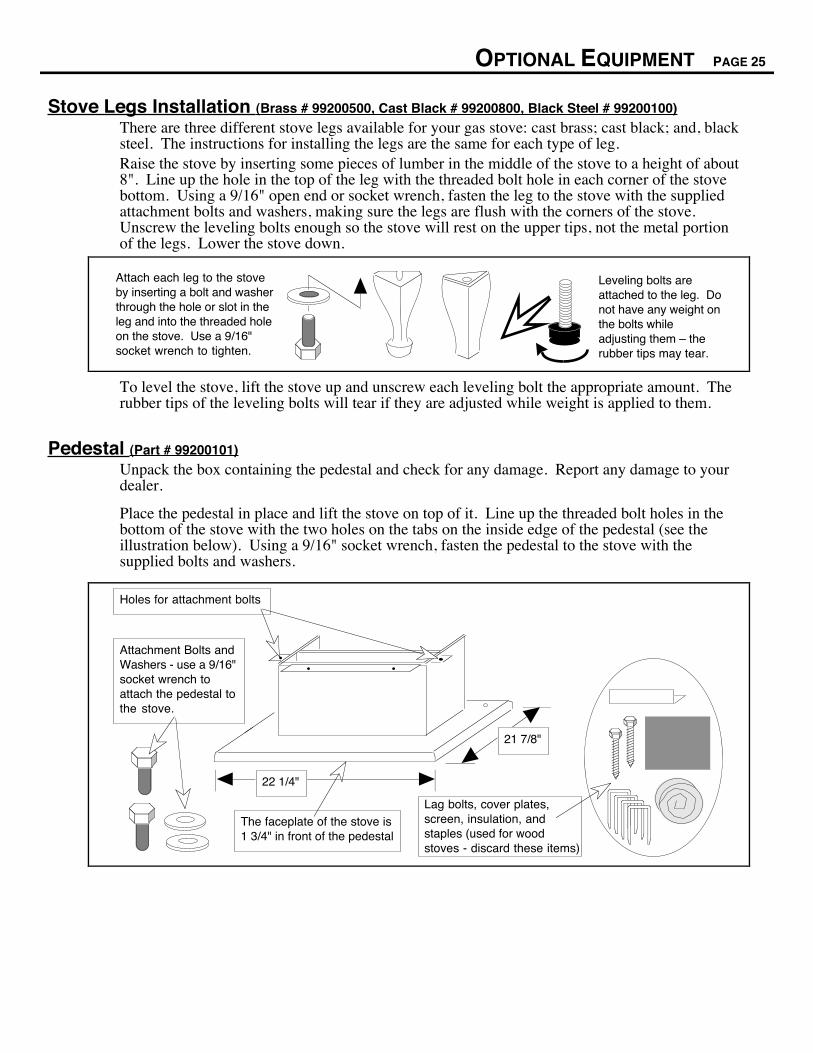
Stove Legs Installation (Brass # 99200500, Cast Black # 99200800, Black Steel # 99200100)
There are three different stove legs available for your gas stove: cast brass; cast black; and, blacksteel. The instructions for installing the legs are the same for each type of leg.Raise the stove by inserting some pieces of lumber in the middle of the stove to a height of about8". Line up the hole in the top of the leg with the threaded bolt hole in each corner of the stovebottom. Using a 9/16" open end or socket wrench, fasten the leg to the stove with the suppliedattachment bolts and washers, making sure the legs are flush with the corners of the stove.Unscrew the leveling bolts enough so the stove will rest on the upper tips, not the metal portionof the legs. Lower the stove down.
Attach each leg to the stove by inserting a bolt and washer through the hole or slot in the leg and into the threaded hole on the stove. Use a 9/16" socket wrench to tighten.
Leveling bolts are attached to the leg. Do not have any weight on the bolts while adjusting them Ð the rubber tips may tear.
To level the stove, lift the stove up and unscrew each leveling bolt the appropriate amount. Therubber tips of the leveling bolts will tear if they are adjusted while weight is applied to them.
Pedestal (Part # 99200101)
Unpack the box containing the pedestal and check for any damage. Report any damage to yourdealer.
Place the pedestal in place and lift the stove on top of it. Line up the threaded bolt holes in thebottom of the stove with the two holes on the tabs on the inside edge of the pedestal (see theillustration below). Using a 9/16" socket wrench, fasten the pedestal to the stove with thesupplied bolts and washers.
Lag bolts, cover plates, screen, insulation, and staples (used for wood stoves - discard these items)
Holes for attachment bolts
21 7/8"
22 1/4"
Attachment Bolts and Washers - use a 9/16" socket wrench to attach the pedestal to the stove.
The faceplate of the stove is 1 3/4" in front of the pedestal
PAGE 26 OPTIONAL EQUIPMENT (CONTINUED)
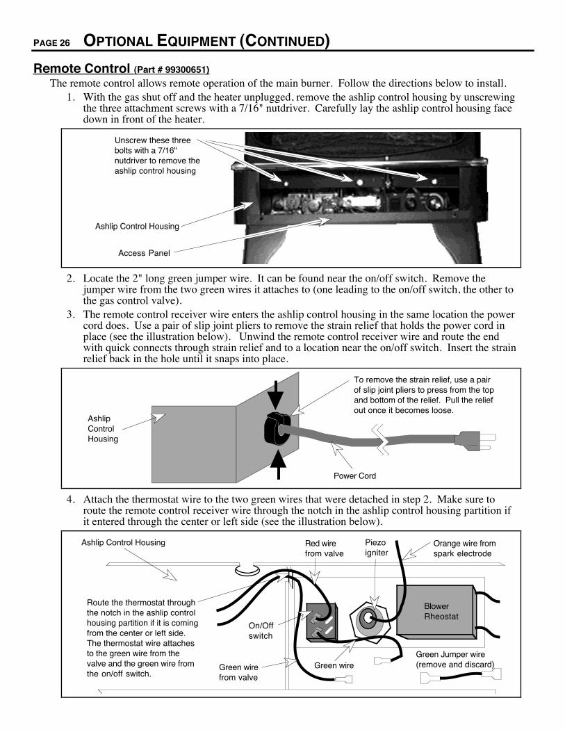
Remote Control (Part # 99300651)
The remote control allows remote operation of the main burner. Follow the directions below to install.1. With the gas shut off and the heater unplugged, remove the ashlip control housing by unscrewing
the three attachment screws with a 7/16" nutdriver. Carefully lay the ashlip control housing facedown in front of the heater.
Unscrew these three bolts with a 7/16" nutdriver to remove the ashlip control housing
Ashlip Control Housing
Access Panel
2. Locate the 2" long green jumper wire. It can be found near the on/off switch. Remove thejumper wire from the two green wires it attaches to (one leading to the on/off switch, the other tothe gas control valve).
3. The remote control receiver wire enters the ashlip control housing in the same location the powercord does. Use a pair of slip joint pliers to remove the strain relief that holds the power cord inplace (see the illustration below). Unwind the remote control receiver wire and route the endwith quick connects through strain relief and to a location near the on/off switch. Insert the strainrelief back in the hole until it snaps into place.
Ashlip Control Housing
Power Cord
To remove the strain relief, use a pair of slip joint pliers to press from the top and bottom of the relief. Pull the relief out once it becomes loose.
4. Attach the thermostat wire to the two green wires that were detached in step 2. Make sure toroute the remote control receiver wire through the notch in the ashlip control housing partition ifit entered through the center or left side (see the illustration below).
Route the thermostat through the notch in the ashlip control housing partition if it is coming from the center or left side. The thermostat wire attaches to the green wire from the valve and the green wire from the on/off switch.
On/Off switch
Piezo igniter
Red wire from valve
Orange wire from spark electrode
Blower Rheostat
Green wire from valve
Green wireGreen Jumper wire(remove and discard)
Ashlip Control Housing

OPTIONAL EQUIPMENT (CONTINUED) PAGE 27
Remote Control (continued)5. Replace the ashlip control housing. Make sure none of the wiring is pinched. Determine the
location of the remote control receiver. Find a location that is within reach of 10' of wire. Routethe remote control receiver wire to the location and connect it to the remote control receiver byattaching the quick connects (the orientation of the wires does not matter).
6. Place a nine volt battery inside the remote control receiver and remote control (see theillustration below).
Mount a 9 volt battery in both the remote control and remote control receiver.
Remove this screw with a phillips head screwdriver.
This clip holds the battery in place.
Attach the remote control receiver wire to these two quick connects.
Remote Control Receiver
7. Mount the remote control receiver to the wall using two screws (not included). The screws passthrough the cover plate and hold the remote control receiver in place.
The distance between the mounting holes is 3 1/4".
The hole must be 2 1/2" tall.
The hole must be 1 3/4" wide.Remote Control Receiver
Cover Plate
The screws insert here (screws not included)
8. Test the remote control's operation prior to leaving the installation. Start the pilot, let it run fiveminutes, then turn the on/off switch on the heater to "ON". Switch the remote control receiver to"REMOTE". Press the remote control for one second to turn the heater on and off. If it does not,check all of the electrical connections and re-test. When the remote control receiver is turned to"ON" the heater will stay on, when on "OFF" the heater will stay off, regardless of the remotecontrol.

PAGE 28 OPTIONAL EQUIPMENT (CONTINUED)
Thermostat (Part # 99300650)
The thermostat allows the main burner to turn on and off automatically for consistent room temperature.Follow the directions below to install.
1. With the gas shut off and the heater unplugged, remove the ashlip control housing by unscrewingthe three attachment screws with a 7/16" nutdriver. Carefully lay the ashlip control housing facedown in front of the heater.
Unscrew these three bolts with a 7/16" nutdriver to remove the ashlip control housing
Ashlip Control Housing
Access Panel
2. Locate the 2" long green jumper wire. It can be found near the on/off switch. Remove thejumper wire from the two green wires it attaches to (one leading to the on/off switch, the other tothe gas control valve - see the illustration on the following page).
3. The thermostat wire enters the ashlip control housing in the same location the power cord does.Use a pair of slip joint pliers to remove the strain relief that holds the power cord in place (seethe illustration below). Unwind the thermostat wire and route the end with quick connectsthrough the strain relief and to a location near the on/off switch. Insert the strain relief back inthe hole until it snaps into place.
Ashlip Control Housing
Power Cord
To remove the strain relief, use a pair of slip joint pliers to press from the top and bottom of the relief. Pull the relief out once it becomes loose.
4. Attach the thermostat wire to the two green wires that were detached in step 2. Make sure toroute the thermostat wire through the notch in the ashlip control housing partition if it enteredthrough the center or left side.
OPTIONAL EQUIPMENT (CONTINUED) PAGE 29
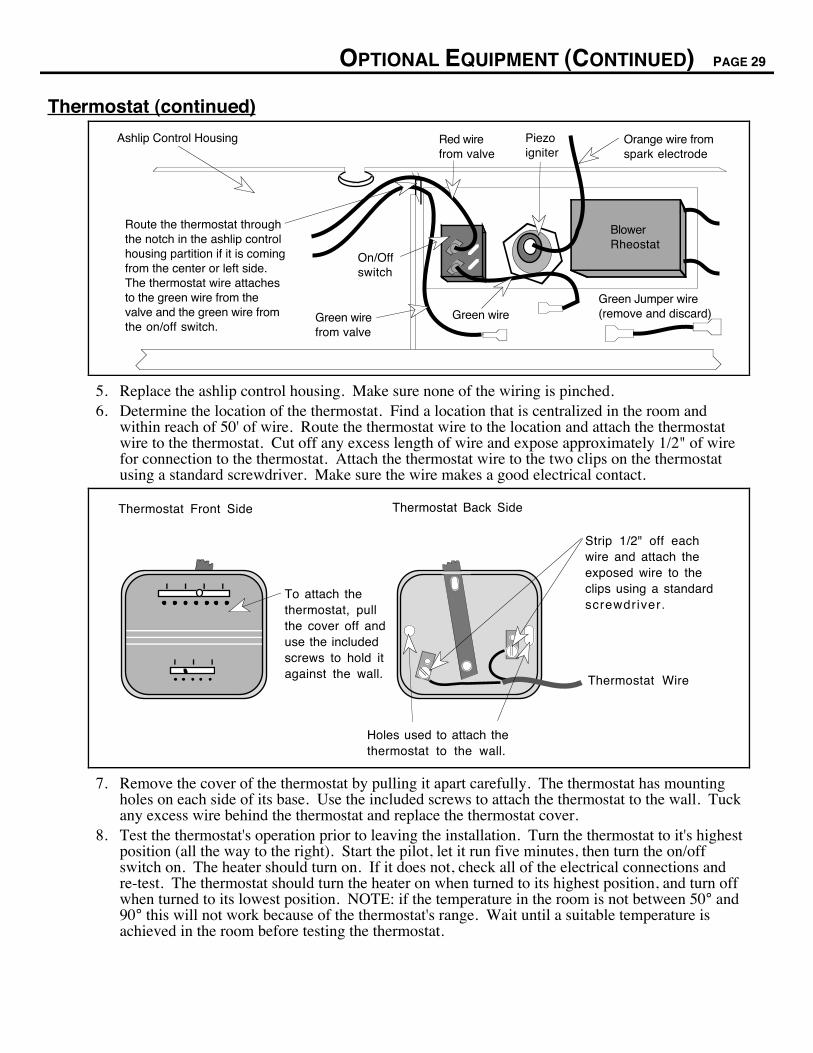
Thermostat (continued)
Route the thermostat through the notch in the ashlip control housing partition if it is coming from the center or left side. The thermostat wire attaches to the green wire from the valve and the green wire from the on/off switch.
On/Off switch
Piezo igniter
Red wire from valve
Orange wire from spark electrode
Blower Rheostat
Green wire from valve
Green wireGreen Jumper wire(remove and discard)
Ashlip Control Housing
5. Replace the ashlip control housing. Make sure none of the wiring is pinched.6. Determine the location of the thermostat. Find a location that is centralized in the room and
within reach of 50' of wire. Route the thermostat wire to the location and attach the thermostatwire to the thermostat. Cut off any excess length of wire and expose approximately 1/2" of wirefor connection to the thermostat. Attach the thermostat wire to the two clips on the thermostatusing a standard screwdriver. Make sure the wire makes a good electrical contact.
To attach the thermostat, pull the cover off and use the included screws to hold it against the wall.
Strip 1/2" off each wire and attach the exposed wire to the clips using a standard screwdriver.
Thermostat Wire
Thermostat Front Side Thermostat Back Side
Holes used to attach the thermostat to the wall.
7. Remove the cover of the thermostat by pulling it apart carefully. The thermostat has mountingholes on each side of its base. Use the included screws to attach the thermostat to the wall. Tuckany excess wire behind the thermostat and replace the thermostat cover.
8. Test the thermostat's operation prior to leaving the installation. Turn the thermostat to it's highestposition (all the way to the right). Start the pilot, let it run five minutes, then turn the on/offswitch on. The heater should turn on. If it does not, check all of the electrical connections andre-test. The thermostat should turn the heater on when turned to its highest position, and turn offwhen turned to its lowest position. NOTE: if the temperature in the room is not between 50° and90° this will not work because of the thermostat's range. Wait until a suitable temperature isachieved in the room before testing the thermostat.

PAGE 30 OPTIONAL EQUIPMENT (CONTINUED)
Re-Routing the Power Cord to the Left or Rear of the Heater
The power cord is normally routed to the right side of the heater. It may be re-routed to the left or rearof the stove. The directions below detail this procedure.
1. TURN THE GAS LINE VALVE TO OFF AND UNPLUG THE HEATER (if the heater isconnected or plugged in).
2. Use slip joint pliers to remove the strain relief that holds the power cord in place (see theillustration below).
Ashlip Control Housing
Power Cord
To remove the strain relief, use a pair of slip joint pliers to press from the top and bottom of the relief. Pull the relief out once it becomes loose.
3. Open the access panel and with a 7/16" nutdriver loosen the three bolts that hold the controlhousing in place. When the control housing becomes loose, lift it off the bolts and place it facedown in front of the heater. The wires that lead to the control housing can then be accessed.
Loosen these three bolts with a 7/16" nutdriver
Ashlip Control Housing
Access Panel
4. Disconnect the molex connector that attaches to the power cord. Remove the power cord fromthe heater by threading the molex plug through the hole in the ashlip control housing (see theillustration below). To route the power cord to the left side, follow step 5A. To route the cord tothe rear (stoves only), follow step 5B.
Blower Rheostat
Disconnect the molex plug to re-route the power cord.
Route the power cord through this notch in the ashlip control housing partition.
This hole if for routing the power cord to the rear of the heater.

OPTIONAL EQUIPMENT (CONTINUED) PAGE 31
Re-Routing the Power Cord to the Left or Rear of the Heater (Continued)
5A Pry the button plug from the left side of the ashlip control housing using a screwdriver (see theillustration below). Insert it in the hole on the right side where the strain relief was removed.Insert the power cord through the hole on the left side. Route the power cord through the notchin the ashlip control housing partition and re-connect the power cord by connecting the molexplugs (see the illustration on the previous page). Place the strain relief over the power cord nextto the ashlip control housing. Compress the strain relief by clamping it with a pair of slip nosepliers. Then insert it into the ashlip control housing until it locks into place.
Button Plug
Remove the button plug by prying it loose with a screwdriver
5B Included in the accessory pack are three cord mounts and a button plug. Insert the button plug inthe hole on the right where the strain relief was removed. Insert the power cord through the holeon the bottom of the ashlip control housing. Route the power cord through the notch in theashlip control housing partition and re-connect the power cord by connecting the molex plugs(see the illustration on the previous page). Place the strain relief over the power cord next to theashlip control housing. Compress the strain relief by clamping it with a pair of slip nose pliers.Then insert it into the ashlip control housing until it locks into place. The cord is hidden underthe heater with the use of cord mounts inserted into the baseplate of the heater. Insert the threecord mounts into the base of the heater (see the illustration below for details). Then insert thepower cord into each cord mount until it latches in place. After installation, pull the slack out ofthe power cord.
Cord mount
Insert the power cord through these two arms until they lock in place.
FOR STOVES WITH PEDESTALSInsert a cord mount into the hole on the right side of the pedestal and route the cord around the base of the pedestal.
FOR STOVES WITH LEGSInsert a cord mount into the hole in the center of the stove and route the cord down the middle of the stove.
Front of S
tove
Ashlip Control Housing
Insert this end in until these barbs expand, locking it in place.
Baseplate
Power Cord Strain Relief
6. Replace the ashlip control housing, making sure no wiring becomes pinched, and tighten thethree bolts that hold it in place.
PAGE 32 INDEX
B vent .......................................................................... 7
Blower Speed............................................................... 15
BTU Input ..................................................................... 5
Cap (vent termination) ................................................. 8
Clearances .................................................................. 6
Controls........................................................................ 11
Dimensions................................................................... 5
Door (inspection, removal, replacing components)...... 18
Door Gasket ................................................................. 18
Emissions..................................................................... 5
Fan Speed ................................................................... 15
Firebox (inspection) ..................................................... 16
Flame Height................................................................ 15
Flexible Tube Note ...................................................... 8
Floor Protection ........................................................... 7
Fuel .............................................................................. 5
Gas Inlet Location ....................................................... 8
Gas Leak............................................ See Inst. on Cover
Gas Line Install ........................................................... 8
Gas Pressure .............................................................. 9
Gas Smell............................................ See Inst. on Cover
Glass, Glass Gasket .................................................... 18
Heater Placement ....................................................... 6
Heating Specifications ................................................. 5
How this Heater Works................................................. 20
Leaking Gas ....................................... See Inst. on Cover
Legs (installation) ......................................................... 25
Listing Information........................................................ 24
Logs and Coals (installation, removal) ......................... 17
Manifold Pressure ....................................................... 9
Natural Gas Verses Propane Heater ........................... 2
On/Off Operation.......................................................... 14
Operating Sounds ........................................................ 15
Operating the Heater .................................................... 13
Paint Curing................................................................. 13
Parts List ..................................................................... 22
Pedestal (installation) ................................................... 25
Pilot (starting) ............................................................... 12
Power Cord (re-routing to rear or left of heater) ........... 30
Propane Line Install (gas line install)........................... 8
Propane Verses Natural Gas Heater........................... 2
Purging Gas Line ........................................................ 9
Remote Control (installation) ....................................... 26
Remote Control (operation) .......................................... 14
Replacement Parts...................................................... 22
Reviewing the Installation ............................................ 10
Running Your Heater................................................... 13
Safety Label ................................................................. 24
Safety Precautions ...................................................... 2
Sounds (normal operating sounds) .............................. 15
Starting The Pilot .......................................................... 12
Starting the Heater for the First Time........................... 13
Stove Clearances......................................................... 6
Table of Contents......................................................... 4
Thermostat (installation)............................................... 28
Thermostat (operation)................................................ 14
Troubleshooting Table................................................. 19
Turning the Heater On and Off.................................... 14
Vent Requirements ..................................................... 7
Vent termination .......................................................... 8
Warranty....................................................................... 23
Weight .......................................................................... 5
What Prevents Gas Buildup ........................................ 21
What Turns the Main Burners On and Off .................... 20
Why Nothing Should Be Placed Against the Heater ... 20
Wiring Diagram............................................................ 22