Embed Size (px)
Citation preview
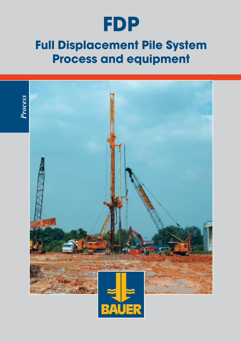
FDPFull Displacement Pile System
Process and equipment
Pro
cess
905-657-X_06-13_FDP.qxd 04.07.2013 9:32 Uhr Seite 1
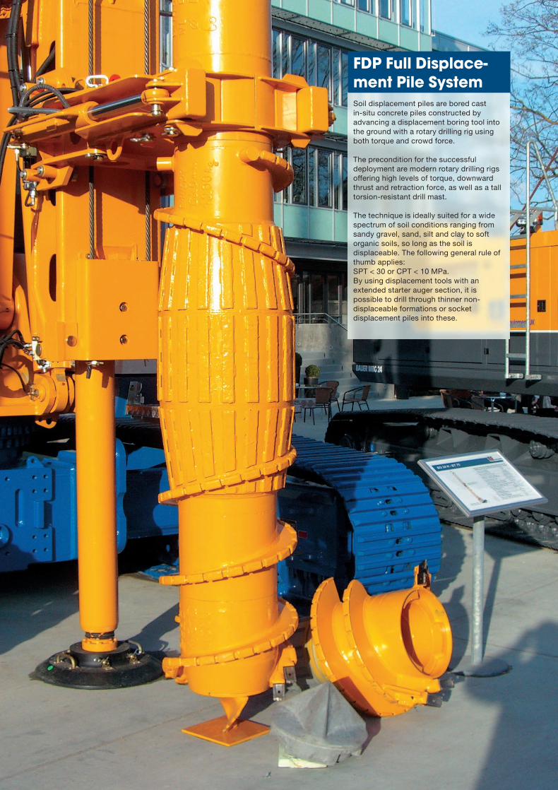
Soil displacement piles are bored cast in-situ concrete piles constructed byadvancing a displacement boring tool intothe ground with a rotary drilling rig usingboth torque and crowd force.
The precondition for the successfuldeployment are modern rotary drilling rigsoffering high levels of torque, downwardthrust and retraction force, as well as a talltorsion-resistant drill mast.
The technique is ideally suited for a widespectrum of soil conditions ranging fromsandy gravel, sand, silt and clay to softorganic soils, so long as the soil isdisplaceable. The following general rule ofthumb applies: SPT < 30 or CPT < 10 MPa.By using displacement tools with anextended starter auger section, it ispossible to drill through thinner non-displaceable formations or socketdisplacement piles into these.
FDP Full Displace-ment Pile System
905-657-X_06-13_FDP.qxd 04.07.2013 9:32 Uhr Seite 2
3
© BAUER Maschinen GmbH, 6/2013
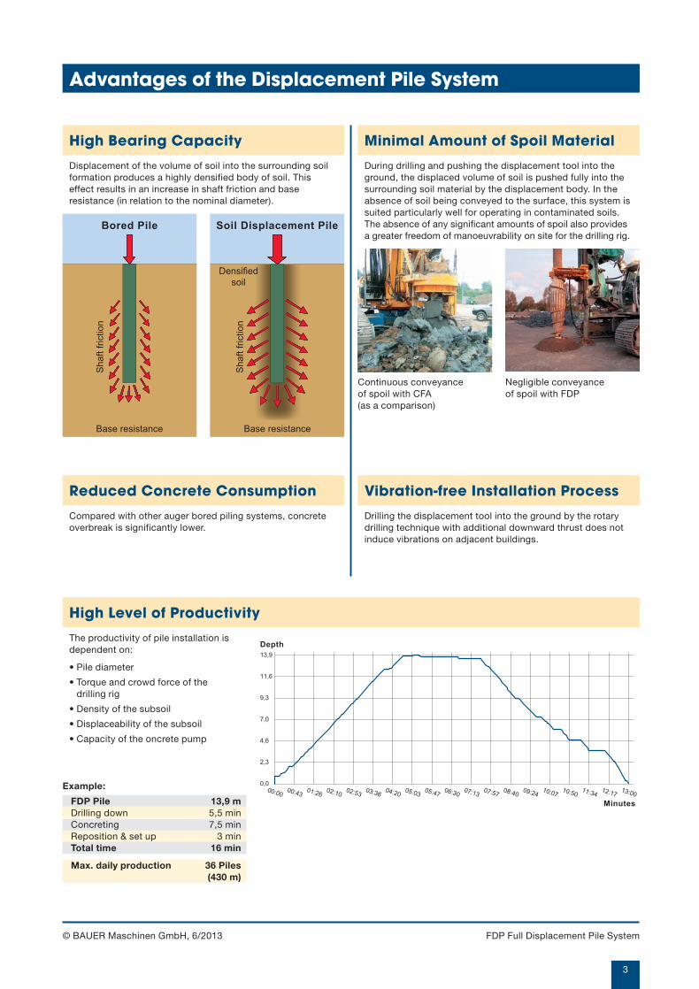
High Bearing Capacity
Displacement of the volume of soil into the surrounding soilformation produces a highly densified body of soil. Thiseffect results in an increase in shaft friction and baseresistance (in relation to the nominal diameter).
Vibration-free Installation Process
Drilling the displacement tool into the ground by the rotarydrilling technique with additional downward thrust does notinduce vibrations on adjacent buildings.
Minimal Amount of Spoil Material
During drilling and pushing the displacement tool into theground, the displaced volume of soil is pushed fully into thesurrounding soil material by the displacement body. In theabsence of soil being conveyed to the surface, this system issuited particularly well for operating in contaminated soils.The absence of any significant amounts of spoil also providesa greater freedom of manoeuvrability on site for the drilling rig.
High Level of Productivity
The productivity of pile installation isdependent on:
• Pile diameter
• Torque and crowd force of the drilling rig
• Density of the subsoil
• Displaceability of the subsoil
• Capacity of the oncrete pump
Reduced Concrete Consumption
Compared with other auger bored piling systems, concreteoverbreak is significantly lower.
Negligible conveyance of spoil with FDP
Continuous conveyance of spoil with CFA (as a comparison)
Depth
Minutes
0,000:00
2,3
4,6
7,0
9,3
11,6
00:4301:26
02:1002:53
03:3604:20
05:0305:47
06:3007:13
07:5708:40
09:2410:07
10:5011:34
12:1713:00
13,9
Example:
FDP Pile 13,9 mDrilling down 5,5 minConcreting 7,5 minReposition & set up 3 minTotal time 16 min
Max. daily production 36 Piles(430 m)
Base resistance
Shaft friction
Bored Pile
Base resistance
Soil Displacement Pile
Densified
soil
Shaft friction
FDP Full Displacement Pile System
Advantages of the Displacement Pile System
905-657-X_06-13_FDP.qxd 04.07.2013 9:32 Uhr Seite 3
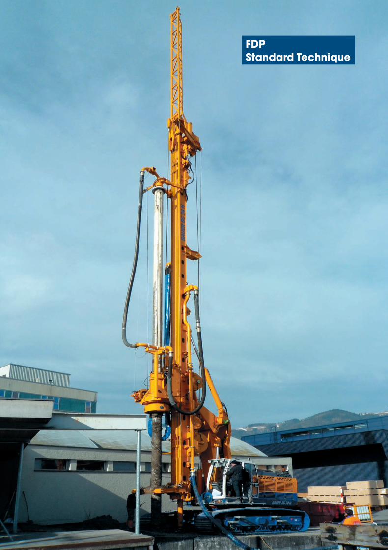
FDP Standard Technique
905-657-X_06-13_FDP.qxd 04.07.2013 9:32 Uhr Seite 4
5
1 2 3 4 5
© BAUER Maschinen GmbH, 6/2013
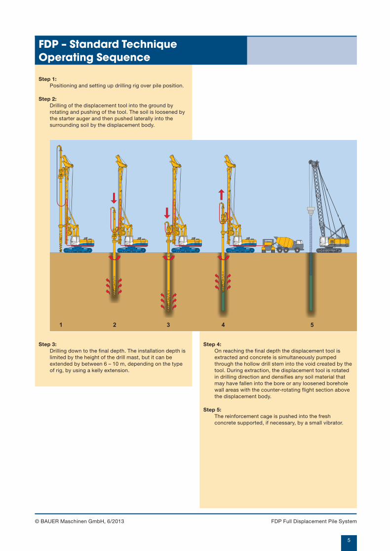
FDP – Standard TechniqueOperating Sequence
Step 1:Positioning and setting up drilling rig over pile position.
Step 2:Drilling of the displacement tool into the ground byrotating and pushing of the tool. The soil is loosened bythe starter auger and then pushed laterally into thesurrounding soil by the displacement body.
Step 4:On reaching the final depth the displacement tool isextracted and concrete is simultaneously pumpedthrough the hollow drill stem into the void created by thetool. During extraction, the displacement tool is rotatedin drilling direction and densifies any soil material thatmay have fallen into the bore or any loosened boreholewall areas with the counter-rotating flight section abovethe displacement body.
Step 5:The reinforcement cage is pushed into the freshconcrete supported, if necessary, by a small vibrator.
Step 3:Drilling down to the final depth. The installation depth islimited by the height of the drill mast, but it can beextended by between 6 – 10 m, depending on the typeof rig, by using a kelly extension.
FDP Full Displacement Pile System
905-657-X_06-13_FDP.qxd 04.07.2013 9:32 Uhr Seite 5
6
© BAUER Maschinen GmbH, 6/2013
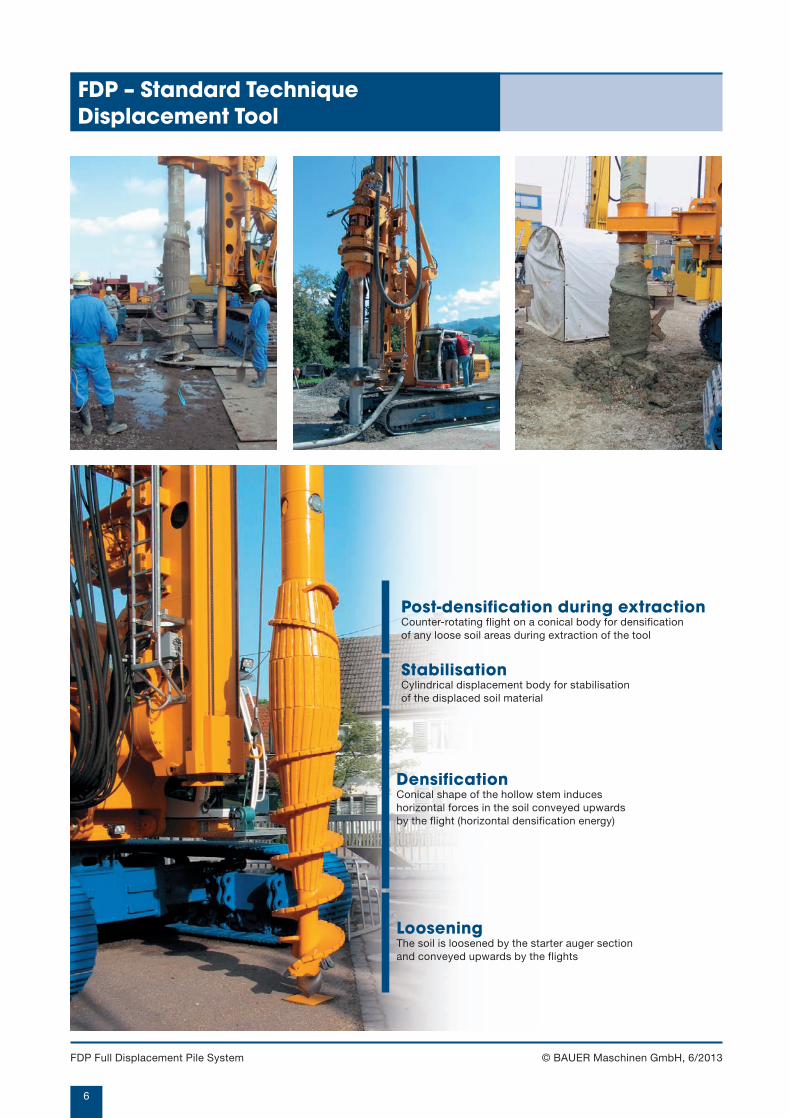
FDP – Standard TechniqueDisplacement Tool
Post-densification during extractionCounter-rotating flight on a conical body for densification of any loose soil areas during extraction of the tool
StabilisationCylindrical displacement body for stabilisation of the displaced soil material
DensificationConical shape of the hollow stem induces horizontal forces in the soil conveyed upwards by the flight (horizontal densification energy)
LooseningThe soil is loosened by the starter auger section and conveyed upwards by the flights
FDP Full Displacement Pile System
905-657-X_06-13_FDP.qxd 04.07.2013 9:32 Uhr Seite 6
7
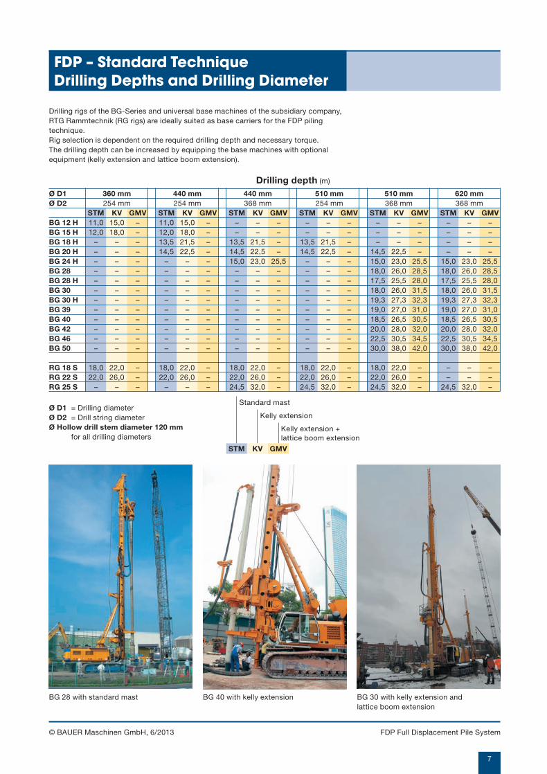
Ø D1 360 mm 440 mm 440 mm 510 mm 510 mm 620 mmØ D2 254 mm 254 mm 368 mm 254 mm 368 mm 368 mm
STM KV GMV STM KV GMV STM KV GMV STM KV GMV STM KV GMV STM KV GMVBG 12 H 11,0 15,0 – 11,0 15,0 – – – – – – – – – – – – –BG 15 H 12,0 18,0 – 12,0 18,0 – – – – – – – – – – – – –BG 18 H – – – 13,5 21,5 – 13,5 21,5 – 13,5 21,5 – – – – – – –BG 20 H – – – 14,5 22,5 – 14,5 22,5 – 14,5 22,5 – 14,5 22,5 – – – –BG 24 H – – – – – – 15,0 23,0 25,5 – – – 15,0 23,0 25,5 15,0 23,0 25,5BG 28 – – – – – – – – – – – – 18,0 26,0 28,5 18,0 26,0 28,5BG 28 H – – – – – – – – – – – – 17,5 25,5 28,0 17,5 25,5 28,0BG 30 – – – – – – – – – – – – 18,0 26,0 31,5 18,0 26,0 31,5BG 30 H – – – – – – – – – – – – 19,3 27,3 32,3 19,3 27,3 32,3BG 39 – – – – – – – – – – – – 19,0 27,0 31,0 19,0 27,0 31,0BG 40 – – – – – – – – – – – – 18,5 26,5 30,5 18,5 26,5 30,5BG 42 – – – – – – – – – – – – 20,0 28,0 32,0 20,0 28,0 32,0BG 46 – – – – – – – – – – – – 22,5 30,5 34,5 22,5 30,5 34,5BG 50 – – – – – – – – – – – – 30,0 38,0 42,0 30,0 38,0 42,0
RG 18 S 18,0 22,0 – 18,0 22,0 – 18,0 22,0 – 18,0 22,0 – 18,0 22,0 – – – –RG 22 S 22,0 26,0 – 22,0 26,0 – 22,0 26,0 – 22,0 26,0 – 22,0 26,0 – – – –RG 25 S – – – – – – 24,5 32,0 – 24,5 32,0 – 24,5 32,0 – 24,5 32,0 –
STM KV GMV
© BAUER Maschinen GmbH, 6/2013
FDP – Standard TechniqueDrilling Depths and Drilling Diameter
BG 28 with standard mast BG 40 with kelly extension BG 30 with kelly extension and lattice boom extension
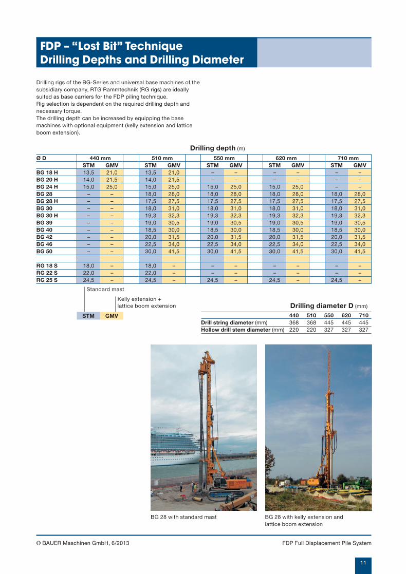
Drilling rigs of the BG-Series and universal base machines of the subsidiary company,RTG Rammtechnik (RG rigs) are ideally suited as base carriers for the FDP pilingtechnique.Rig selection is dependent on the required drilling depth and necessary torque.The drilling depth can be increased by equipping the base machines with optionalequipment (kelly extension and lattice boom extension).
Ø D1 = Drilling diameterØ D2 = Drill string diameter Ø Hollow drill stem diameter 120 mm
for all drilling diameters
Drilling depth (m)
Standard mast
Kelly extension
Kelly extension + lattice boom extension
FDP Full Displacement Pile System
905-657-X_06-13_FDP.qxd 04.07.2013 9:33 Uhr Seite 7

As a variant, the FDP soil displacement pilesystem can also be deployed with asacrificial drill bit. It differs from thestandard technique by a detachable full-face drill bit, a hollow drill stem with alarger internal diameter and a concretehopper that is mounted at the top of thehollow stem. With this set-up concrete canbe placed in the pile by gravity feed alonewithout the application of pressure.Due to the "unpressurised" placement ofthe concrete, excessive consumption ofconcrete is kept to a minimum particularlyin soft soils. It also reduces the risk of thedisplacement body becoming jammedduring concreting.
FDP “Lost Bit”Technique
905-657-X_06-13_FDP.qxd 04.07.2013 9:33 Uhr Seite 8
9
© BAUER Maschinen GmbH, 6/2013
FDP – “Lost Bit” TechniqueOperating Sequence
Concrete
Camera
1 2 3 4 5
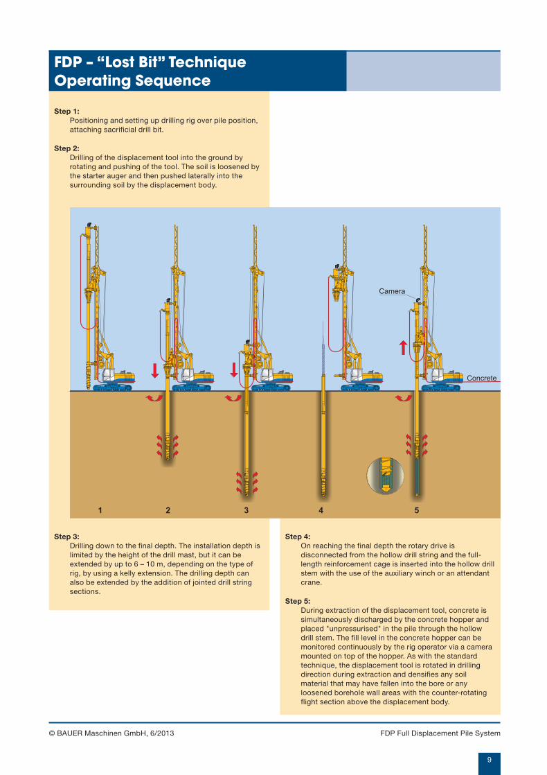
Step 1:Positioning and setting up drilling rig over pile position,attaching sacrificial drill bit.
Step 2:Drilling of the displacement tool into the ground byrotating and pushing of the tool. The soil is loosened bythe starter auger and then pushed laterally into thesurrounding soil by the displacement body.
Step 4:On reaching the final depth the rotary drive isdisconnected from the hollow drill string and the full-length reinforcement cage is inserted into the hollow drillstem with the use of the auxiliary winch or an attendantcrane.
Step 5:During extraction of the displacement tool, concrete issimultaneously discharged by the concrete hopper andplaced "unpressurised" in the pile through the hollowdrill stem. The fill level in the concrete hopper can bemonitored continuously by the rig operator via a cameramounted on top of the hopper. As with the standardtechnique, the displacement tool is rotated in drillingdirection during extraction and densifies any soilmaterial that may have fallen into the bore or anyloosened borehole wall areas with the counter-rotatingflight section above the displacement body.
Step 3:Drilling down to the final depth. The installation depth islimited by the height of the drill mast, but it can beextended by up to 6 – 10 m, depending on the type ofrig, by using a kelly extension. The drilling depth canalso be extended by the addition of jointed drill stringsections.
FDP Full Displacement Pile System
905-657-X_06-13_FDP.qxd 04.07.2013 9:33 Uhr Seite 9
10
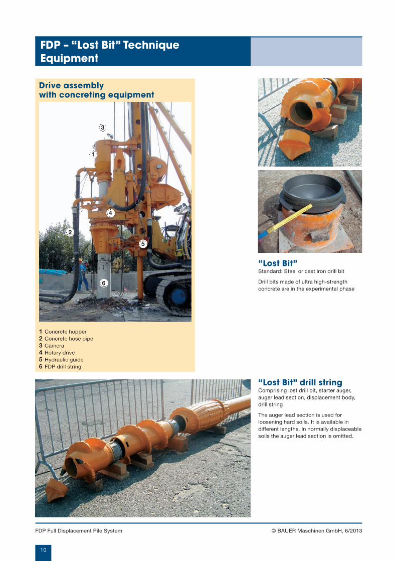
1
2
3
4
5
6
© BAUER Maschinen GmbH, 6/2013
“Lost Bit”Standard: Steel or cast iron drill bit
Drill bits made of ultra high-strengthconcrete are in the experimental phase
Drive assembly with concreting equipment
1 Concrete hopper2 Concrete hose pipe3 Camera4 Rotary drive5 Hydraulic guide6 FDP drill string
“Lost Bit” drill stringComprising lost drill bit, starter auger,auger lead section, displacement body,drill string
The auger lead section is used forloosening hard soils. It is available indifferent lengths. In normally displaceablesoils the auger lead section is omitted.
FDP – “Lost Bit” TechniqueEquipment
FDP Full Displacement Pile System
905-657-X_06-13_FDP.qxd 04.07.2013 9:33 Uhr Seite 10
11
440 510 550 620 710368 368 445 445 445220 220 327 327 327
Ø D 440 mm 510 mm 550 mm 620 mm 710 mmSTM GMV STM GMV STM GMV STM GMV STM GMV
BG 18 H 13,5 21,0 13,5 21,0 – – – – – –BG 20 H 14,0 21,5 14,0 21,5 – – – – – –BG 24 H 15,0 25,0 15,0 25,0 15,0 25,0 15,0 25,0 – –BG 28 – – 18,0 28,0 18,0 28,0 18,0 28,0 18,0 28,0BG 28 H – – 17,5 27,5 17,5 27,5 17,5 27,5 17,5 27,5BG 30 – – 18,0 31,0 18,0 31,0 18,0 31,0 18,0 31,0BG 30 H – – 19,3 32,3 19,3 32,3 19,3 32,3 19,3 32,3BG 39 – – 19,0 30,5 19,0 30,5 19,0 30,5 19,0 30,5BG 40 – – 18,5 30,0 18,5 30,0 18,5 30,0 18,5 30,0BG 42 – – 20,0 31,5 20,0 31,5 20,0 31,5 20,0 31,5BG 46 – – 22,5 34,0 22,5 34,0 22,5 34,0 22,5 34,0BG 50 – – 30,0 41,5 30,0 41,5 30,0 41,5 30,0 41,5
RG 18 S 18,0 – 18,0 – – – – – – –RG 22 S 22,0 – 22,0 – – – – – – –RG 25 S 24,5 – 24,5 – 24,5 – 24,5 – 24,5 –
STM GMV
© BAUER Maschinen GmbH, 6/2013
BG 28 with standard mast BG 28 with kelly extension andlattice boom extension
Drilling rigs of the BG-Series and universal base machines of thesubsidiary company, RTG Rammtechnik (RG rigs) are ideallysuited as base carriers for the FDP piling technique.Rig selection is dependent on the required drilling depth andnecessary torque.The drilling depth can be increased by equipping the basemachines with optional equipment (kelly extension and latticeboom extension).
Drilling depth (m)
Standard mast
Kelly extension + lattice boom extension Drilling diameter D (mm)
Drill string diameter (mm)Hollow drill stem diameter (mm)
FDP – “Lost Bit” TechniqueDrilling Depths and Drilling Diameter
FDP Full Displacement Pile System
905-657-X_06-13_FDP.qxd 04.07.2013 9:33 Uhr Seite 11
12
© BAUER Maschinen GmbH, 6/2013
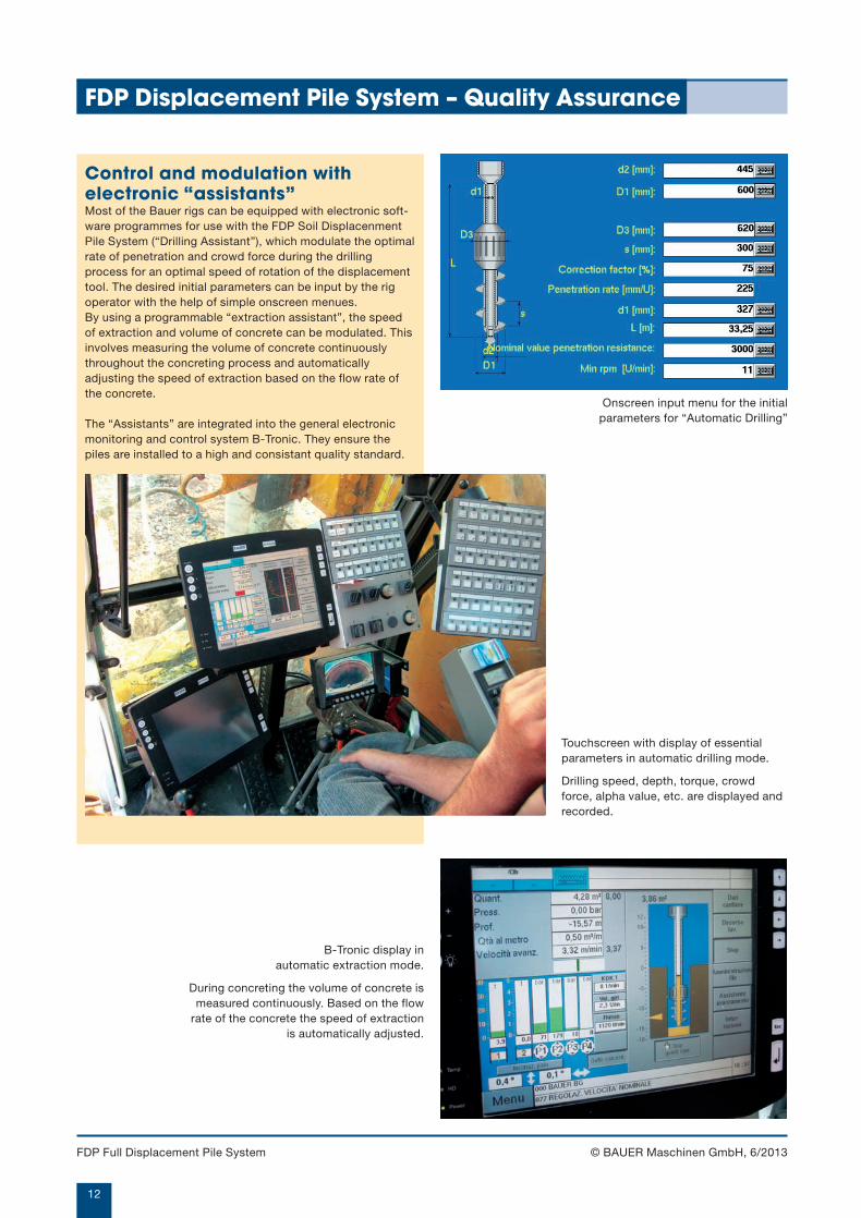
Control and modulation withelectronic “assistants”Most of the Bauer rigs can be equipped with electronic soft-ware programmes for use with the FDP Soil DisplacenmentPile System (“Drilling Assistant”), which modulate the optimalrate of penetration and crowd force during the drillingprocess for an optimal speed of rotation of the displacementtool. The desired initial parameters can be input by the rigoperator with the help of simple onscreen menues. By using a programmable “extraction assistant”, the speedof extraction and volume of concrete can be modulated. Thisinvolves measuring the volume of concrete continuouslythroughout the concreting process and automaticallyadjusting the speed of extraction based on the flow rate ofthe concrete.
The “Assistants” are integrated into the general electronicmonitoring and control system B-Tronic. They ensure thepiles are installed to a high and consistant quality standard.
Onscreen input menu for the initialparameters for “Automatic Drilling”
Touchscreen with display of essentialparameters in automatic drilling mode.
Drilling speed, depth, torque, crowdforce, alpha value, etc. are displayed andrecorded.
B-Tronic display in automatic extraction mode.
During concreting the volume of concrete ismeasured continuously. Based on the flow
rate of the concrete the speed of extractionis automatically adjusted.
FDP Displacement Pile System – Quality Assurance
FDP Full Displacement Pile System
905-657-X_06-13_FDP.qxd 04.07.2013 9:33 Uhr Seite 12
13
1 2 3 4 5 6 7 8
© BAUER Maschinen GmbH, 6/2013
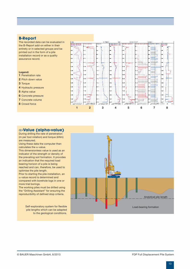
B-ReportThe recorded data can be evaluated inthe B-Report add-on either in theirentirety or in selected groups and beprinted out in the form of a pileinstallation record or as a qualityassurance record.
Legend:1 Penetration rate
2 Pitch down value
3 Torque
4 Hydraulic pressure
5 Alpha value
6 Concrete pressure
7 Concrete volume
8 Crowd force
Load-bearing formation
Analytical pile length
�-Value (alpha-value)During drilling the rate of penetration (m per tool rotation) and torque (kNm)are measured.Using these data the computer thencalculates the �-value.This dimensionless value is used as anindicator of the strength or density ofthe prevailing soil formation. It providesan indication that the required loadbearing horizon of a pile is beingreached and can, therefore, be used tooptimise the pile length.Prior to starting the pile installation, an�-value record is determined andcompared with borehole logs in one ormore trial borings.The working piles must be drilled usingthe “Drilling Assistant” for ensuring thereproducibility of defined stop criteria.
Self-exploratory system for flexible pile lengths which can be adapted
to the geological conditions.
FDP Full Displacement Pile System
905-657-X_06-13_FDP.qxd 04.07.2013 9:33 Uhr Seite 13
14
© BAUER Maschinen GmbH, 6/2013
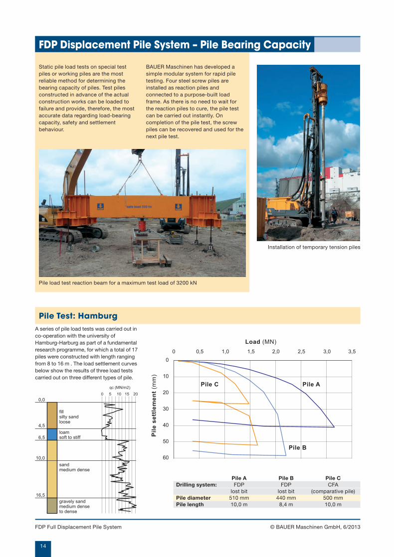
Static pile load tests on special testpiles or working piles are the mostreliable method for determining thebearing capacity of piles. Test pilesconstructed in advance of the actualconstruction works can be loaded tofailure and provide, therefore, the mostaccurate data regarding load-bearingcapacity, safety and settlementbehaviour.
Pile load test reaction beam for a maximum test load of 3200 kN
Installation of temporary tension piles
BAUER Maschinen has developed asimple modular system for rapid piletesting. Four steel screw piles areinstalled as reaction piles andconnected to a purpose-built loadframe. As there is no need to wait forthe reaction piles to cure, the pile testcan be carried out instantly. Oncompletion of the pile test, the screwpiles can be recovered and used for thenext pile test.
A series of pile load tests was carried out inco-operation with the university ofHamburg-Harburg as part of a fundamentalresearch programme, for which a total of 17piles were constructed with length rangingfrom 8 to 16 m . The load settlement curvesbelow show the results of three load testscarried out on three different types of pile.
fillsilty sandloose
loamsoft to stiff
sandmedium dense
0,0
4,5
6,5
10,0
16,5
gravely sandmedium dense to dense
0 5 10 15 20
qc (MN/m2)
0
10
20
30
40
50
60
0 0,5 1,0 1,5 2,0 2,5 3,0 3,5
Load (MN)
Pil
e s
ett
lem
en
t (m
m)
Pile A
Pile B
Pile C
Pile A Pile B Pile CDrilling system: FDP FDP CFA
lost bit lost bit (comparative pile)Pile diameter 510 mm 440 mm 500 mmPile length 10,0 m 8,4 m 10,0 m
Pile Test: Hamburg
FDP Displacement Pile System – Pile Bearing Capacity
FDP Full Displacement Pile System
905-657-X_06-13_FDP.qxd 04.07.2013 9:34 Uhr Seite 14
15
© BAUER Maschinen GmbH, 6/2013
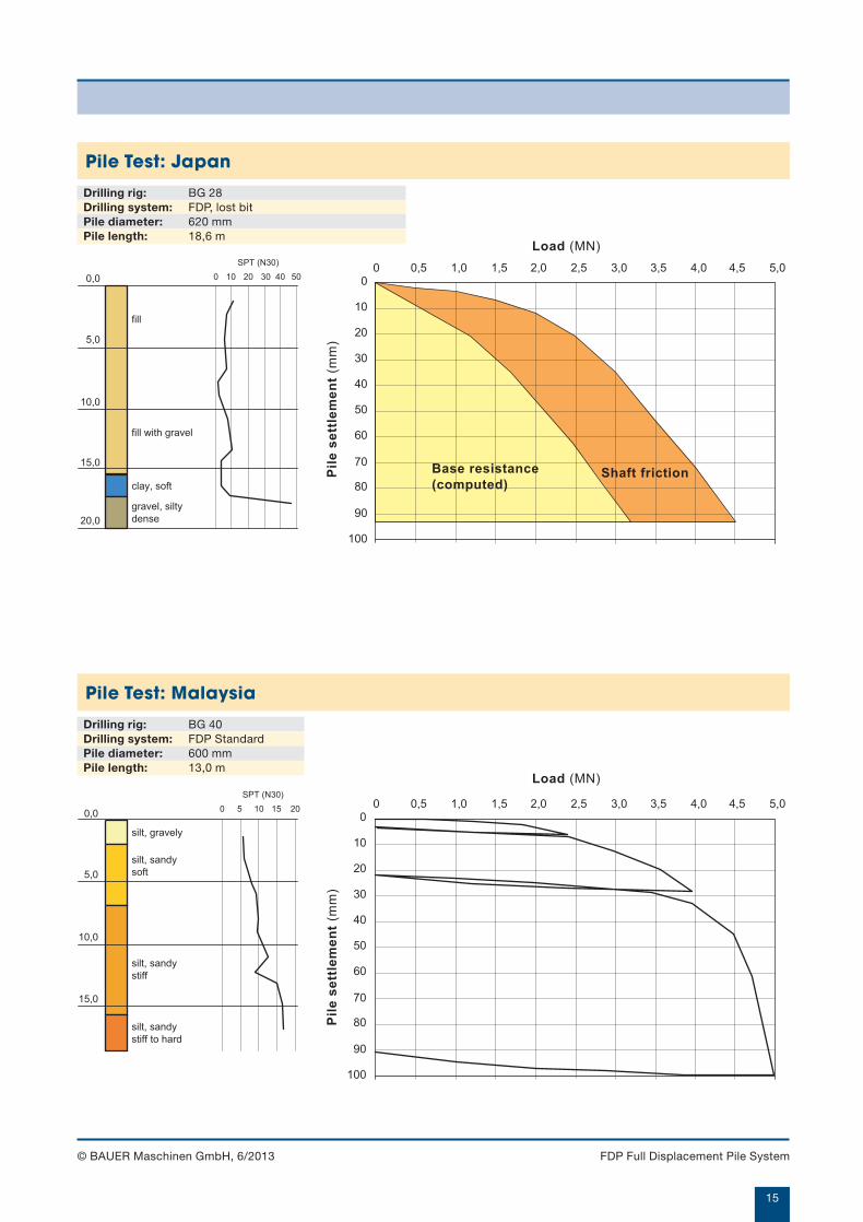
Drilling rig: BG 28Drilling system: FDP, lost bitPile diameter: 620 mmPile length: 18,6 m
Pile Test: Japan
0,0
5,0
10,0
15,0
20,0
0 10 20 30 40 50
SPT (N30)
fill
fill with gravel
clay, soft
gravel, silty
dense
0
10
20
30
40
50
60
70
80
90
100
0 0,5 1,0 1,5 2,0 2,5 3,0 3,5 4,0 4,5 5,0
Load (MN)
Shaft frictionBase resistance
(computed)
Pil
e s
ett
lem
en
t (m
m)
Drilling rig: BG 40Drilling system: FDP StandardPile diameter: 600 mmPile length: 13,0 m
Pile Test: Malaysia
silt, gravely
silt, sandy
soft
silt, sandy
stiff
0,0
5,0
10,0
15,0
silt, sandy
stiff to hard
0 5 10 15 20
SPT (N30)
0
10
20
30
40
50
60
70
80
90
100
0 0,5 1,0 1,5 2,0 2,5 3,0 3,5 4,0 4,5 5,0
Load (MN)
Pil
e s
ett
lem
en
t (m
m)
FDP Full Displacement Pile System
905-657-X_06-13_FDP.qxd 04.07.2013 9:34 Uhr Seite 15
BAUER Maschinen GmbHBAUER-Straße 1D-86529 SchrobenhausenTel. +49 (0)82 52/97-0Fax +49 (0)82 52/97-1135e-mail: [email protected]
Design developments and process improvements may require thespecification and materials to be updated and changed withoutprior notice or liability. Illustrations may include optional equipmentand not show all possible configurations. These and the technical data are provided as indicative informationonly, with any errors and misprints reserved.
905.657.2 6/2013
905-657-X_06-13_FDP.qxd 04.07.2013 9:34 Uhr Seite 16