Embed Size (px)
Citation preview
HARDWARE LIST
Head Cap Bolt14 pcs. (+1 extra)
Hex Wrench1 pc.
Pull Handle2 pcs.
Machine Screw for Pull Handle4 pcs.
Wood Screwfor Caster16 pcs. (+2 extra)
Adjustable Pin8 pcs. (+2 extra)
Wood Plug10 pcs.(+2 extra)
Thai Patent Pending Numbers 077214
88 9100 001 C Kitchen Cart (Natural Finish)
A.Side Panel
1 pc.
PART LIST
B.Side Panel1 pc.
H. Back Panel3 pcs.
F. Back Post2 pcs.
E. Front Post2 pcs.
I.Back Stretcher1 pc.
J.Front Stretcher1 pc.
K.Front Rail3 pcs.
G.Base1 pc.
R.Shelf2 pcs.
L.Side Rack
1 pc.
M.Side Rack1 pc.
OBrush Chrome Pipes 3 pcs.
Q.Round Arm
1 pc.
P.Handle Arm2 pcs.
D.Middle Panel1 pc.
C.Middle Panel
1 pc.
N.Base Rack1 pc.
Tools Required For Assembly : Philips screwdriver
T.Door1 pc.
S.Door1 pc.
U.KD. Drawer3 pcs.
V.KD. Drawer1 pc.
(For Drawer U&V packed in separate carton with hardware and assembly instructions.)
Castertwo locktwo non-lock 4 pcs.
IMPORTANT NOTE
Carefully remove all the parts from the carton and put them individually on a soft cloth to prevent scratches or other damages occuring to the wood parts.
We have taken great care in the design of this product and request that you carefully and strictly follow our assembly instructions to ensure a completed product as it was designed. Casual Attire For Today's Home
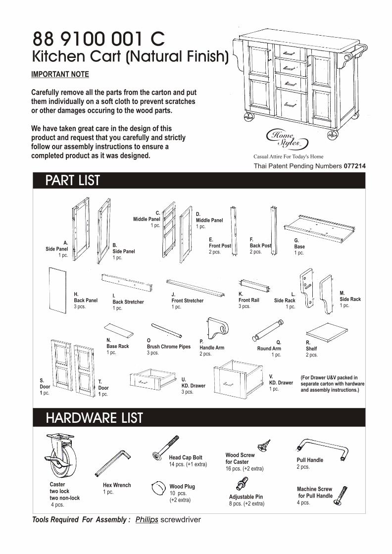
Assembly Instructions 2/3
STEP 1
STEP 2
STEP 3
G
D
G
H H H
K
K
K
CD
A
C
Attach 4 Casters to the underside of the Base (G), put the 2 Casters with lock in front as you first need to lock the cart from moving. (See sticker in the bottom indicating front side)
Put the Front Rail (K) in between the Middle Frame (C) and (D).
Attach the Side Panel (A) to the side of the unit with Head Cap Bolts.
Slide the Back Panels (H) into place.
Attach the Back Post (F) and Front Post (E) to the Middle Panel(C) and (D).
Attach the assembled Middle Panel (C) and (D) to the Base (G).
IMPORTANTDo not tighten up all the screws until each part is properly assembled.You should keep Hex Wrench in the safe place as you may need to tighten up the Head Cap Bolts in the future.
F
C
E
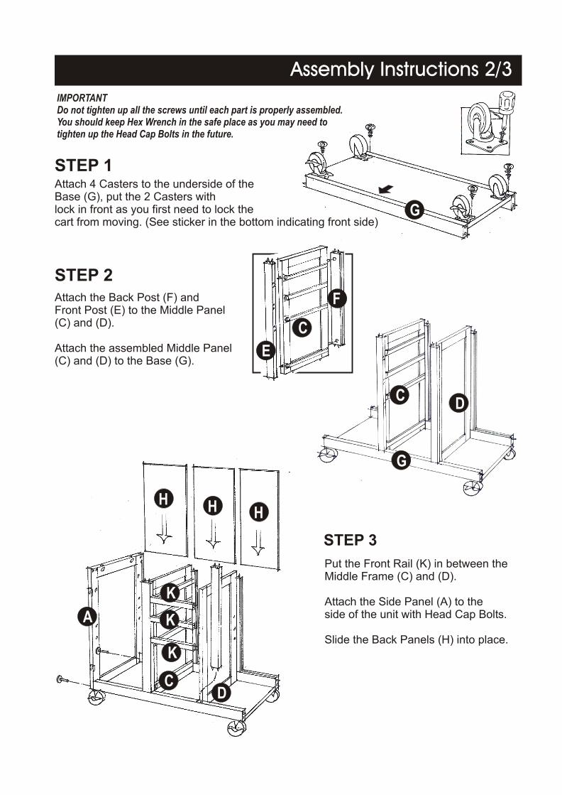
STEP 5
STEP 4
STEP 6
STEP 7
Attach the Handle Arm (P) to the Side Panel (B) with Head Cap Bolts.
Slide the Round Arm (Q) into place.
Attach the Back and Front Stretcher (I), (J) to the assembled unit with Head Cap Bolts.
Attach the Side Panel (B) to the other sideof the unit with Head Cap Bolts.
Assembly Instructions 3/3
J
B
I
N
O
O
O
P
A
C DR
R
B
P QB
L
A
M
Attach the Side Rack (L) to the Side Panel (A)with the Head Cap Bolts.
Attach the Brush Chrome Pipes (O) to the pre-drilledholes of Side Rack (L).
Attach the Base Rack (N) to the Side Rack (L).
Attach the Side Rack (M) to the Side Panel (A),using Head Cap Bolts.
Insert the Adjustable Pins into the Side Panel (A), Middle Panel (C) and SidePanel (B), Middle Panel (D) at the desired level. Place Shelf (R) into place.
Assembly Instructions
Unit Part List
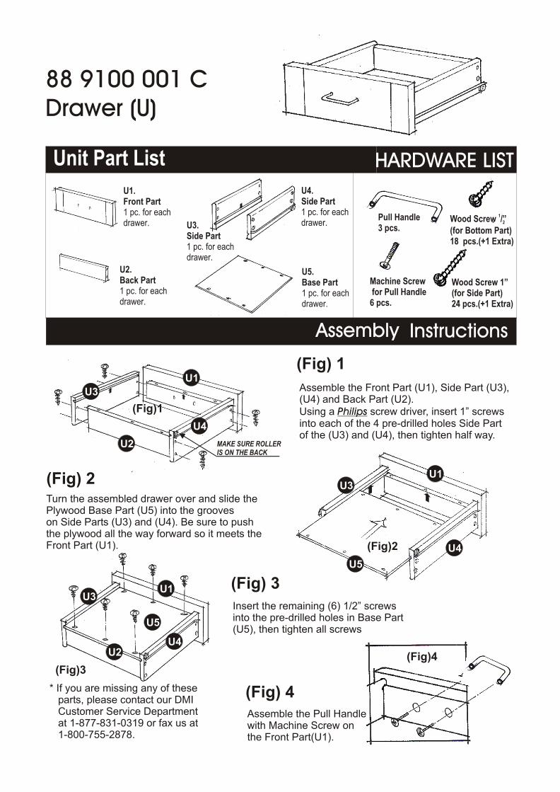
U3.Side Part1 pc. for eachdrawer.
U4.Side Part1 pc. for each drawer.
U5.Base Part1 pc. for eachdrawer.
U2.Back Part1 pc. for eachdrawer.
U2
U2
U5
U5
U3
U4
U4
U4
U3
U3
U1
U1
U1
(Fig) 2
(Fig) 3
(Fig) 4Assemble the Pull Handle with Machine Screw onthe Front Part(U1).
(Fig)1
(Fig)2
(Fig)3(Fig)4
Turn the assembled drawer over and slide the Plywood Base Part (U5) into the grooveson Side Parts (U3) and (U4). Be sure to pushthe plywood all the way forward so it meets the Front Part (U1).
HARDWARE LIST
Pull Handle3 pcs.
Machine Screw for Pull Handle6 pcs.
1Wood Screw /”2
(for Bottom Part)18 pcs.(+1 Extra)
Wood Screw 1”(for Side Part)24 pcs.(+1 Extra)
(Fig) 1
Insert the remaining (6) 1/2” screwsinto the pre-drilled holes in Base Part(U5), then tighten all screws
MAKE SURE ROLLERIS ON THE BACK
* If you are missing any of these parts, please contact our DMI Customer Service Department at 1-877-831-0319 or fax us at 1-800-755-2878.
U1.Front Part1 pc. for eachdrawer.
88 9100 001 CDrawer (U)
Assemble the Front Part (U1), Side Part (U3),(U4) and Back Part (U2).Using a Philips screw driver, insert 1” screwsinto each of the 4 pre-drilled holes Side Part of the (U3) and (U4), then tighten half way.
Assembly Instructions
Unit Part List
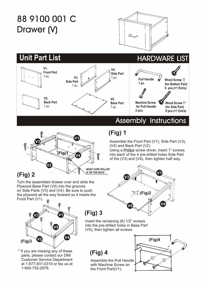
V3.Side Part
1 pc.
V4.Side Part1 pc.
V5.Base Part1 pc.
V2.Back Part1 pc.
V2
V2
V5
V5
V3
V4
V4
V4
V3
V3
V1
V1
V1
(Fig) 2
(Fig) 3
(Fig) 4Assemble the Pull Handle with Machine Screw onthe Front Part(V1).
(Fig)1
(Fig)2
(Fig)3 (Fig)4
Turn the assembled drawer over and slide the Plywood Base Part (V5) into the grooveson Side Parts (V3) and (V4). Be sure to pushthe plywood all the way forward so it meets the Front Part (V1).
HARDWARE LIST
Pull Handle1 pc.
Machine Screw for Pull Handle2 pcs.
1Wood Screw /”2
(for Bottom Part)6 pcs.(+1 Extra)
Wood Screw 1”(for Side Part)8 pcs.(+1 Extra)
(Fig) 1
Insert the remaining (6) 1/2” screwsinto the pre-drilled holes in Base Part(V5), then tighten all screws
MAKE SURE ROLLERIS ON THE BACK
* If you are missing any of these parts, please contact our DMI Customer Service Department at 1-877-831-0319 or fax us at 1-800-755-2878.
V1.Front Part1 pc.
Assemble the Front Part (V1), Side Part (V3),(V4) and Back Part (V2).Using a Philips screw driver, insert 1” screwsinto each of the 4 pre-drilled holes Side Part of the (V3) and (V4), then tighten half way.
88 9100 001 CDrawer (V)