Embed Size (px)
Citation preview

8792Power TubeLinear Beam Power Amplifier Tube
• 1000 Watts Peak Sync Output in VHF
Translator Service
• 265 Watt Average-Noise-Power Output
with White Noise Loading
• 300 Watt Power Output in UHF-Linear
Telephony Service
• 1200 Watts PEP Output in SSB
Suppressed-Carrier Service CERMOLOX®
• Full Input to 400 MHz
The BURLE 8792 is designed specifically to meet thehigh linearity and low noise requirements of moderndata transmission and communication systems. Itssturdy construction makes it ideal for use in portableor mobile equipments.
The design linearity has been evaluated using Method2206 of MIL-STD-1311. This method employs whitenoise with a Gaussian amplitude distribution to checkthe inherent distortion in power amplifiers over abroad operating spectrum. The 8792 tested betterthan the -40 dB specified for Government high-performance equipments for data transmission. Thistest checks the linearity for all methods of modulationboth continuous (amplitude, frequency and phase)and also pulse (position, amplitude and duration).
The 8792 is also rated for SSB - suppressed carrierservice where it can deliver up to 1200 watts of peakenvelope power at a third order intermodulationdistortion of -37 dB when tested with “Two ToneModulation” (Method 2204 of MIL-STD-1311). It canalso supply in excess of 300 watts of useful poweroutput in linear telephony applications.
The sturdy, low-inductance, coaxial construction ofthe 8792 enables the use of simple, economical circuittechniques in all HF, VHF, and UHF applications.
Its large, matrix-oxide cathode enhances systemreliability and life, while the efficient forced-air-cooledradiator reduces system air requirements and permitsreliable, low-temperature operation.
This bulletin gives application information unique tothe BURLE 8792. General information, covering theinstallation and operation of this tube type, is given inthe “Application Guide for BURLE Power Tubes”,
TP-105. Close attention to the instructions containedtherein will assure longer tube life, safer operation,less equipment downtime, and fewer tube handlingaccidents.
General DataElectrical
Heater-Cathode:
Type Unipotential, Oxide Coated, Matrix Type
Voltage1 (AC or DC) 5.5 typ. V
5.8 max. V
Current (@5.5 V) 17.3 A
Minimum heating time 180 s
Mu Factor 7
(Grid No.1 to grid No.2)
Direct Interelectrode Capacitances:
Grid No.1 to plate2 0.2 max. pF
Grid No.1 to cathode-heater 38 pF
Plate to cathode-heater2 0.03 max. pF
Grid No.1 to grid No.2 52 pF
Grid No.2 to plate 16 pF
Grid No.2 to cathode-heater2 2.0 max. pF
Mechanical
Operating Position Any
Maximum Length 84.8 mm (3.34 in)
Greatest Diameter 95.3 mm (3.75 in)
Terminal Connection See Dimensional Outline
Socket See Mounting Arrangement
Radiator Integral Part of Tube
Weight (Approx.) 0.9 kg (2 Ibs)
Thermal
Seal Temperature3 250 max. °C
(Plate, grid No.1, grid No.2
cathode-heater, and heater)
Plate Core Temperature3 250 max. ° C

Linear RF Power Amplifier1
Single-Sideband, Suppressed-CarrierServiceMaximum CCS Ratings, Absolute-Maximum Values
Up to 400 MHz
DC Plate Voltages1 3500 V
DC Grid-No.2 Voltage1 1000 V
DC Plate Current at Peak of Envelope4 1.25 A
Grid-No.2 Input1 50 W
Plate Dissipation 1.8 kW
Maximum Circuit ValuesGrid-No.1 Circuit Resistance:
With fixed bias 5000 ohms
With cathode bias Not Recommended
Grid-No.2 Circuit Impedance See note 1
Plate Circuit Impedance See note 1
Typical Class AB, CCS Operation with“Two-Tone” Modulation
In a grid-drive circuit at 30 MHz
DC Plate Voltage 2500 2500 V
DC Grid-No.2 Voltage 600 600 V
DC Grid-No.1 Voltage5 -65 -61 V
Zero-Signal DC Plate Current 0.5 0.6 A
Effective RF Load Resistance 1050 1050 ohms
DC Plate Current at Peak of Envelope 1.0 1.1 A
Average DC Plate Current .0.75 0.85 A
DC Grid-No.2 Current at
Peak of Envelope -0.020 -0.022 A
Average DC Grid-No.2 Current -0.014 -0.017 A
Peak RF Grid-No.1 Voltage 50 47 V
Output Circuit Efficiency (Approx.) 90 90 %
Useful Power Output (Approx.):
Average 530 600 W
Peak envelope 1060 1200 W
Distortion Products Level6:
Third order 357 377 dB
Fifth order 457 477 dB
Unbypassed Cathode Resistor 0 0 ohm
Typical Class AB, CCS Operation with WhiteNoise Loading as Specified in Method 2206of MIL-STD-1311
At 4.0 MHz
DC Plate Voltage 2500 2500 V
DC Grid-No.2 Voltage 600 600 V
DC Grid-No. 1 Voltage -74 -70 V
Zero Signal DC Plate Current 500 600 mA
RF Load Resistance 1500 1000 ohms
Average DC Plate Current 560 695 mA
Average DC Grid-No.2 Current -10 -11 mA
Driver Power Output8 4.5 8.5 W
Output Circuit Efficiency 90 90 %
Noise Power Ratio (NPR) -40 -40 dB
Unbypassed Cathode Resistor 0 5 ohms
Useful Noise Power Output (NP0) 200 265 W
Linear RF Power Amplifier1 Class AB or Class BTelephonyCarrier conditions for use with a maximum modulation factor of 1.0.
Maximum CCS Ratings, Absolute-Maximum ValuesDC Plate Voltage1 3500 V
DC Grid-No.2 Voltage1 1000 V
DC Plate Current 700 mA
Grid-No.2 Input 50 W
Plate Dissipation 1800 W
Calculated CCS Operation as a Class AB1 AmplifierIn a cathode drive circuit at 400 MHz with an output circuit bandwidth
of 3.5 MHz9.
DC Plate Voltage 2600 A
DC Grid-No.2 Voltage1 500 V
DCGrid-No.1 Voltage10 -65 V
DC Plate Current 550 mA
DC Grid-No.1 Current 0 A
DC Grid-No.2 Current -10 mA
Drive Power (Approx.) 25 W
Output Circuit Eff. (Approx.) 90 %
Useful Power Output 300 W
Linear RF Power AmplifierVHF Translator Service, Class ABSynchronizing-level conditions per tube unless otherwise specified.
Maximum CCS Ratings, Absolute-Maximum ValuesDC Plate Voltage 3500 V
DC Grid-No.2 Voltage 1000 V
DC Plate Current 1.25 A
Plate Dissipation 1800 W
Grid-No.2 Input 50 W
Typical OperationIn a cathode-drive circuit with video RF drive at 200 MHz and a
1.0 dB bandwidth of 6.5 MHz min.
DC Plate Voltage 2500 V
DC Grid-No.2 Voltage 600 V
DC Grid-No.1 Voltage -55 V
DC Plate Current::
Zero signal 0.6 A
Synchronizing level 1.25 A
Pedestal level 0.9 A
DC Grid-No.2 Current:
Synchronizing level -50 mA
DC Grid-No.1 Current:
Synchronizing level 0 mA
Drive Power Output:
Synchronizing level 63 W
Pedestal level 38 W
Useful Power Output:
Synchronizing level 1000 W
Pedestal level 600 W
Inter Mod Distortion -54 dB
Measured with 3 Tone input signal under CCIR conditions. Visual
carrier adjusted to-8 dB below 1 kW level. Aural carrier at-7 dBand
and the color subcarrier at -17 dB.
Warning - Personal Safety HazardsElectrical Shock - Operating voltagesapplied to this device present a shock hazard
.
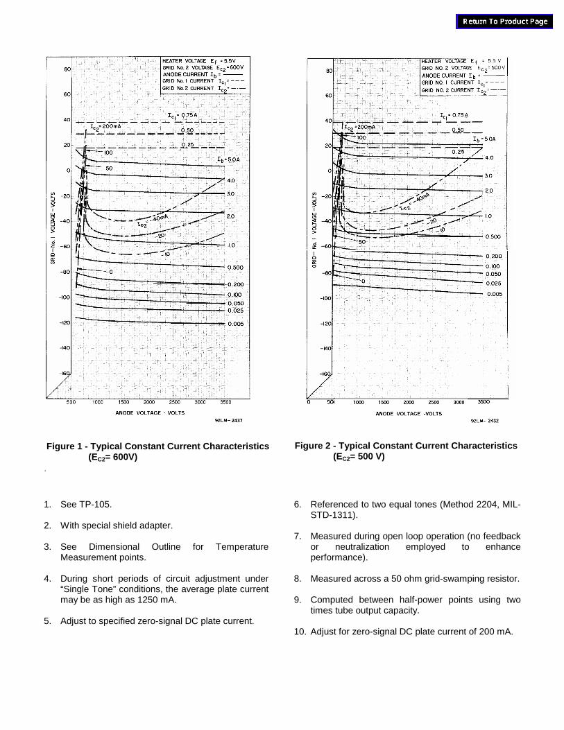
1. See TP-105.
2. With special shield adapter.
3. See Dimensional Outline for TemperatureMeasurement points.
4. During short periods of circuit adjustment under“Single Tone” conditions, the average plate currentmay be as high as 1250 mA.
5. Adjust to specified zero-signal DC plate current.
6. Referenced to two equal tones (Method 2204, MIL-STD-1311).
7. Measured during open loop operation (no feedbackor neutralization employed to enhanceperformance).
8. Measured across a 50 ohm grid-swamping resistor.
9. Computed between half-power points using twotimes tube output capacity.
10. Adjust for zero-signal DC plate current of 200 mA.
Figure 1 - Typical Constant Current Characteristics(EC2= 600V)
Figure 2 - Typical Constant Current Characteristics(EC2= 500 V)
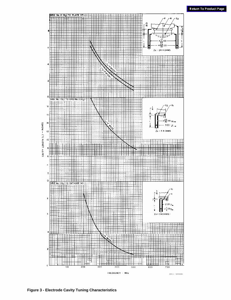
Figure 3 - Electrode Cavity Tuning Characteristics
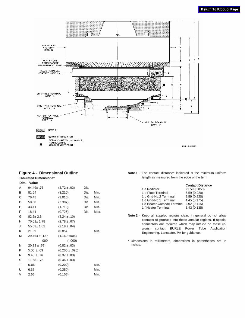
Figure 4 - Dimensional OutlineTabulated Dimensions*
Dim. Value
A 94.49± .76 (3.72 ± .03) Dia.
B 81.54 (3.210) Dia. Min.
C 76.45 (3.010) Dia. Min.
D 58.60 (2.307) Dia. Min.
E 43.41 (1.710) Dia. Min.
F 18.41 (0.725) Dia. Max.
G 82.3± 2.5 (3.24 ± .10)
H 70.61± 1.78 (2.78 ± .07)
J 55.63± 1.02 (2.19 ± .04)
K 21.59 (0.85) Min.
M 29.464 + .127 (1.160 +005)
-000 (-.000)
N 20.83 ± .76 (0.82 ± .03)
P 5.08 ± .63 (0.200 ± .025)
R 9.40 ± .76 (0.37 ± .03)
S 11.68± .76 (0.46 ± .03)
T 5.08 (0.200) Min.
U 6.35 (0.250) Min.
V 2.66 (0.105) Min.
Note 1 - The contact distance* indicated is the minimum uniformlength as measured from the edge of the term
Contact Distance1.a Radiator 21.59 (0.850)1.b Plate Terminal 5.59 (0.220)1.c Grid-No.2 Terminal 5.59 (0.220)1.d Grid-No.1 Terminal 4.45 (0.175)1.e Heater-Cathode Terminal 2.92 (0.115)1.f Heater Terminal 3.43 (0.135)
Note 2 - Keep all stippled regions clear. In general do not allowcontacts to protrude into these annular regions. If specialconnectors are required which may intrude on these re-gions, contact BURLE Power Tube ApplicationEngineering, Lancaster, PA for guidance.
* Dimensions in millimeters, dimensions in parentheses are ininches.
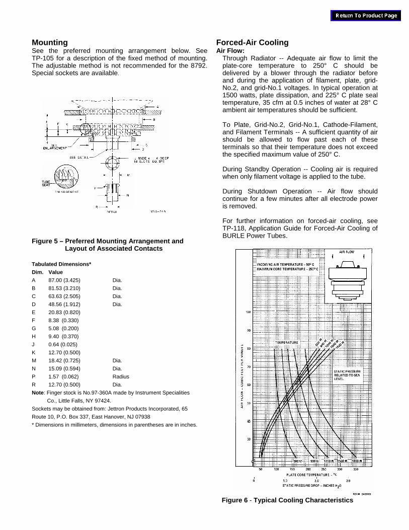
MountingSee the preferred mounting arrangement below. SeeTP-105 for a description of the fixed method of mounting.The adjustable method is not recommended for the 8792.Special sockets are available.
Figure 5 – Preferred Mounting Arrangement andLayout of Associated Contacts
Tabulated Dimensions*
Dim. Value
A 87.00 (3.425) Dia.
B 81.53 (3.210) Dia.
C 63.63 (2.505) Dia.
D 48.56 (1.912) Dia.
E 20.83 (0.820)
F 8.38 (0.330)
G 5.08 (0.200)
H 9.40 (0.370)
J 0.64 (0.025)
K 12.70 (0.500)
M 18.42 (0.725) Dia.
N 15.09 (0.594) Dia.
P 1.57 (0.062) Radius
R 12.70 (0.500) Dia.
Note: Finger stock is No.97-360A made by Instrument Specialities
Co., Little Falls, NY 97424.
Sockets may be obtained from: Jettron Products Incorporated, 65
Route 10, P.O. Box 337, East Hanover, NJ 07938
* Dimensions in millimeters, dimensions in parentheses are in inches.
Forced-Air CoolingAir Flow:
Through Radiator -- Adequate air flow to limit theplate-core temperature to 250° C should bedelivered by a blower through the radiator beforeand during the application of filament, plate, grid-No.2, and grid-No.1 voltages. In typical operation at1500 watts, plate dissipation, and 225° C plate sealtemperature, 35 cfm at 0.5 inches of water at 28° Cambient air temperatures should be sufficient.
To Plate, Grid-No.2, Grid-No.1, Cathode-Filament,and Filament Terminals -- A sufficient quantity of airshould be allowed to flow past each of theseterminals so that their temperature does not exceedthe specified maximum value of 250° C.
During Standby Operation -- Cooling air is requiredwhen only filament voltage is applied to the tube.
During Shutdown Operation -- Air flow shouldcontinue for a few minutes after all electrode poweris removed.
For further information on forced-air cooling, seeTP-118, Application Guide for Forced-Air Cooling ofBURLE Power Tubes.
Figure 6 - Typical Cooling Characteristics