Embed Size (px)
Citation preview
8791/V1Power Tube
VHF-TV Amplifier Tube
• CERMOLOX®
• Ruggedized, Reliable
• Matrix Oxide Cathode
• Full Input to 400 MHz
• 1000 W Peak Sync Output in VHF-TV Service
The BURLE 8791/V1 is designed specifically to meetthe stringent requirements of modern VHF-TVequipments. Its high gain, CERMOLOX® tubeconstruction and full input rating to 400 MHz make itideally suited for high frequency applications such asVHF-TV grid-modulated service and VHF or UHFClass B linear service where it will deliver better thanone kilowatt peak sync or 200 watts carrier outputrespectively.
The ruggedized, low inductance, coaxial constructionof the 8791/V1 enables the use of simple, economicalcircuit techniques in all HF, VHF, and UHFapplications.
Its matrix oxide cathode enhances system reliabilitywhile the efficient, forced-air cooled radiator reducessystem air requirements and permits more reliable,lower temperature operation.
To comply with environmental design objectives,design samples are subjected to 50 g-3/4 millisecondshock; 500 g-3/4 millisecond shock; and 20 g-2000hertz vibration testing.
This bulletin gives application information unique to theBURLE 8791/V1. General information, covering theinstallation and operation of this tube type, is given inthe “Application Guide for BURLE Power Tubes”,TP-105. Close attention to the instructions containedtherein will assure longer tube life, safer operation, lessequipment downtime, and fewer tube handlingaccidents.
General Data
Electrical
Heater-Cathode:Type…………… Unipotential, Oxide Coated, Matrix TypeVoltage1 (ac or dc)………………….. 5.5 typ. V
6.6 max VCurrent at 5.5 volts…………………. 7.2 AMinimum Heating Time……………….. 120 sMu-Factor, (Grid No.2 to Grid No.1)… 13Direct Interelectrode Capacitances:2
Grid No.1 to plate…………………….. 0.10 max. pFGrid No.1 to cathode & heater……… 28 pFPlate to cathode & heater…………… 0.010 max. pFGrid No.1 to grid No.2……………….. 36 pFGrid No.2 to plate……………………. 5.1 pFGrid No.2 to cathode & heater……… 1.0 max. pF
Mechanical
Operating Position………………….. AnyOverall Length…………..………….. 62.0 mm (2.44 in) max.Greatest Diameter…………..….….. 64.8 mm (2.55 in) max.Terminal Connections…………… See Dimensional OutlineSockets…………..…………..………. See page 2Radiator…………..…………..……… Integral part of tubeWeight (Approx.) …………..………. 0.3 kg (3/4 Ib)
Thermal
Seal Temperature3(Plate, Grid No.2)Grid No.1, Cathode-Heater and Heater)... 250 max. °CPlate-Core Temperature………………….. 250 max. °C
Grid-Modulated RF Power Amplifier -Class C Television Service4
Synchronizing-level conditions per tube unless otherwise specifiedMaximum CCS Ratings, Absolute-Maximum Values
up to 216 MHzDC Plate Voltage4……………………………………….. 3000 VDC Grid-No.2 Voltage4…………………………………… 750 VDC Grid-No. 1 Voltage
(White Level)……………………………………………. -250 VDC plate Current…………………………………………. 750 mAGrid-No.2 Input…………………………………………….. 25 WPlate Dissipation…………………………………………. 1000 WGrid-No. 1 Current…………………………………………. 100 mA
Calculated OperationGrid-drive circuit at 216 MHz at a bandwidth of 8.5 MHz5
DC Plate Voltage ....................................................... 2700 VDC Grid-No.2 Voltage .................................................. 450 VDC Grid-No. 1 Voltage:
Synchronizing level .................................................... -70 VBlanking level............................................................. -80 VWhite level ............................................................... -110 V
Peak RF Grid-No. 1 Voltage .......................................... 70 VDC Plate Current:Synchronizing level ..................................................... 700 mABlanking level............................................................. 500 mA
DC Grid-No.1 Current (Approx.):Synchronizing level ......................................................... 0 ABlanking level................................................................. 0 A
Driver Power Output (Approx.):Synchronizing level ...................................................... 8.0 WBlanking level.............................................................. 4.5 W
Useful Power Output (Approx.):Synchronizing level ................................................... 1100 WBlanking level............................................................. 615 W
Linear RF Power Amplifier4
Class AB or Class B TelephonyCarrier conditions for use with a maximum modulation factor of 1.0Maximum CCS Ratings, Absolute-Maximum Values:DC Plate Voltage4 ..................................................... 3000 VDC Grid-No.2 Voltage4.................................................. 75 VDC Plate Current......................................................... 500 mAGrid-No.2 Input ............................................................. 25 WPlate Dissipation ....................................................... 1000 W
Calculated CCS Operation as a Class AB1AmplifierIn a cathode drive circuit, at 400 MHz with an output circuitbandwidth of 10.0 MHz5
DC Plate Voltage…………………………………….. 2500 VDC Grid-No.2 Voltage……………………………… 450 VDC Grid-No. 1 Voltage……………………………… -45 VDC Plate Current…………………………………….. 340 mADC Grid-No. 1 Current……………………………… 0 ADC Grid-No. 2 Current……………………………… -2.0 mADrive Power…………………………………………... 8.0 WOutput Circuit Efficiency (Approx.) ………………… 80 %Useful Power Output……………………………….. 200 W
Characteristics Range ValuesMin. Max.
Heater Current6………………………… 6.9 8.3 ADirect Interelectrode Capacitances:Grid No.1 to plate7……………………… - 0.010 pFGrid No.1 to cathode & heater7……….. 27 32 pFPlate to cathode & heater7…………….. - 0.010 pFGrid No.1 to grid No.27………………… 34 41 pFGrid No.2 to plate7……………………… 4.5 6.0 pFGrid No.2 to cathode & heater7……… - 1.0 pFReverse Grid-No.1 Current6,8…………. - -50 µAInterelectrode LeakageResistance9……………………………… 8.0 - MohmsCutoff Grid-No. 1 Voltage76,10…………. - -82 VGrid-No. 1 Voltage6,8…………………… -25 -42 VSocket……………………………… Erie 9706-011
Jettron 89-083 or equivalent
Sockets may be obtained from: Jettron Products Incorporated,56 Route 10, Hanover, NJ 07936.
1. For maximum life expectancy, the heater-voltage must be ad-justed initially and throughout life to the lowest value that willgive the desired performance.1. Before the application of any other voltages to a new tube,
the heater voltage should be adjusted 5.5 volts at the tubesocket. A true RMS voltmeter should be used for accuratemeasurement.
2. Apply voltages and adjust tuning controls as necessary forproper operation as described in the appropriate instructionmanual.
3. Reduce the heater voltage in 0.1-volt increments --repeating Step 2 until performance degradation is noted.Then increase the heater voltage 0.1 volt above this point.Typically, depending upon the application, this voltage willbe in the range of 4.8 to 5.5 volts.
During life when evidence is observed that a tube is becomingemission limited, increasing the heater voltage may extend theuseful life of the tube. However, never increase heater voltageto compensate for a decrease in other circuit parameters suchas RF drive or video modulating voltage!
2. Measured with special Adapter.3. See Dimensional Outline for temperature measurement points.4. See TP-105.5. Computed between half-power points and based on 1-1/2
times tube output capacity.6. With 6.3 V ac or dc on heater.7. Measured with special shield adapter.8. With dc plate voltage of 2500 volts, dc grid-No.2 voltage of 400
volts, and dc grid-No.1 voltage adjusted to give a plate currentof 240 mA.
9. Under conditions with tube at 20° to 30 °C for at least 30minutes without any voltages applied to the tube. The minimumresistance between any two electrodes (except across heaterterminals) is measured with a 200-volt Megger-type ohmmeterhaving an internal impedance of 1.0 megohm.
10. With dc plate voltage of 2500 volts, dc grid-No.2 voltage of 400volts, and dc grid-No.1 voltage adjusted to give a plate currentof 5 mA.
MountingSee the preferred mounting arrangement in Figure 5. SeeTP105 for a description of the fixed method of mounting.The adjustable method is not recommended for the8791/V1. Special sockets are available. (See page 2.)
Forced-Air CoolingAir Flow:Through radiator -- Adequate air flow to limit the plate-coretemperature to 250 °C should be delivered by a blowerthrough the radiator before and during the application ofheater, plate, grid-No.2, and grid-No.1 voltages. In typicaloperation at 750 watts plate dissipation and 200 °C platecore temperature 12 cfm at 0.36 inch of water at 22 °Cambient air temperature should be sufficient as shown onAir Flow Chart.
To Plate, Grid-No.2, Grid-No.1, Heater Cathode, and HeaterTerminals -- A sufficient quantity of air should be allowed toflow past each of these terminals so that their temperaturedoes not exceed the specified maximum value of 250 °C.
During Standby Operation -- Cooling air is required whenonly heater voltage is applied to the tube.
During Shutdown Operation --Air flow should continue for afew minutes after all electrode power is removed.
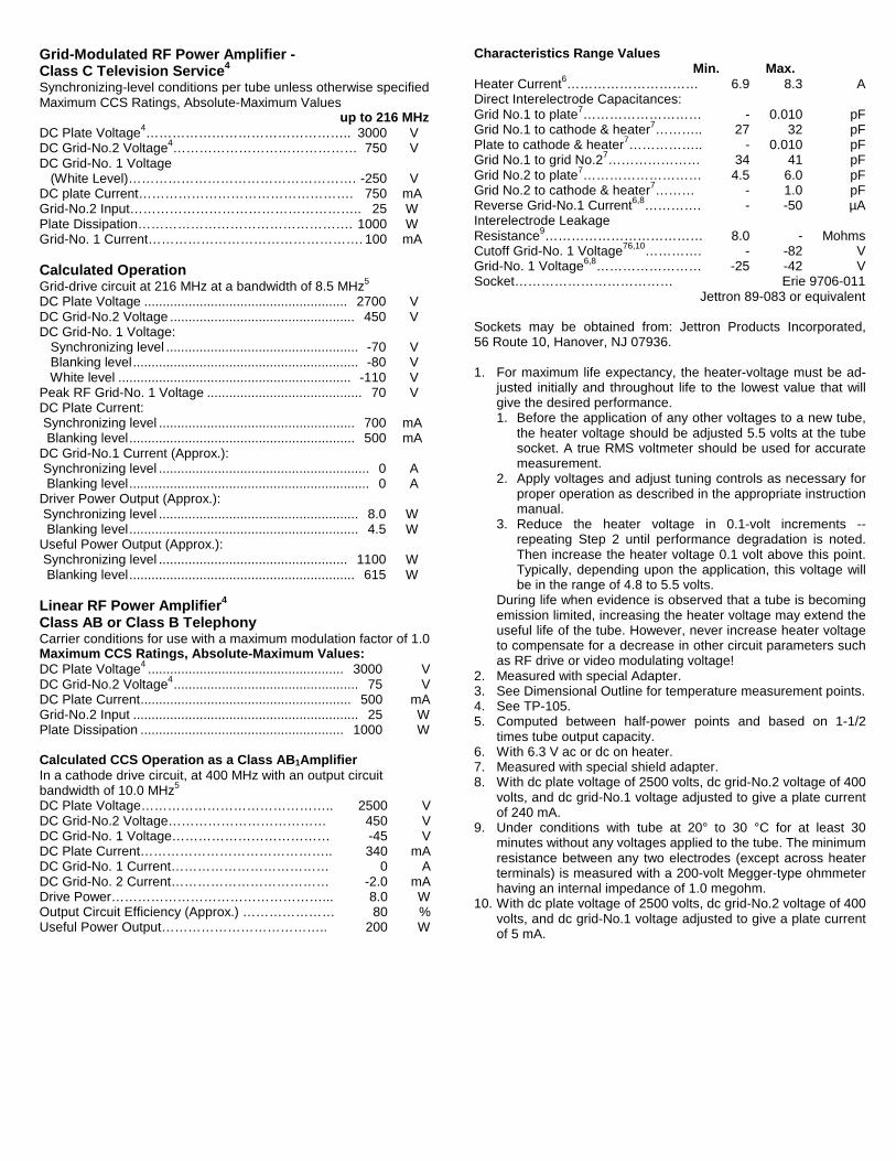
Figure 1 - Typical Constant Current Characteristics(EC2 350 V)
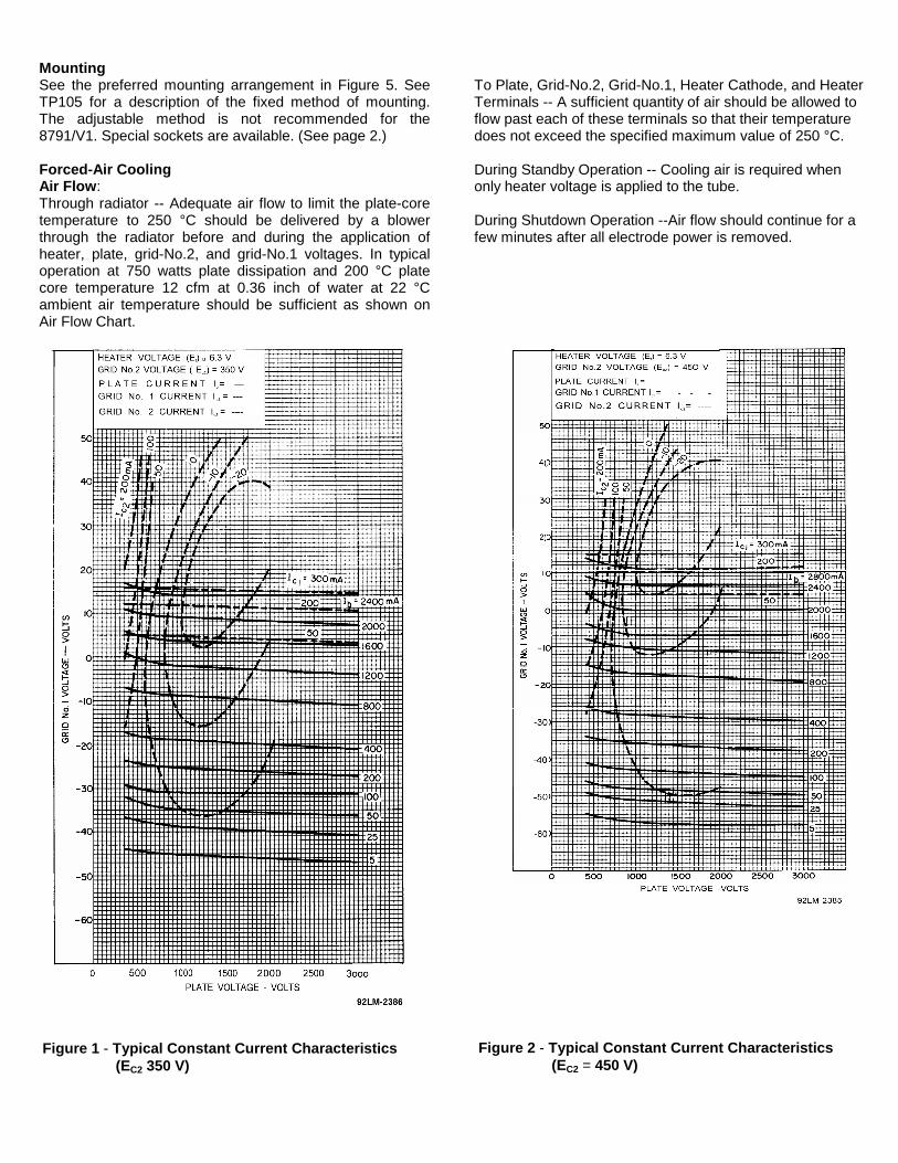
Figure 2 - Typical Constant Current Characteristics(EC2 = 450 V)
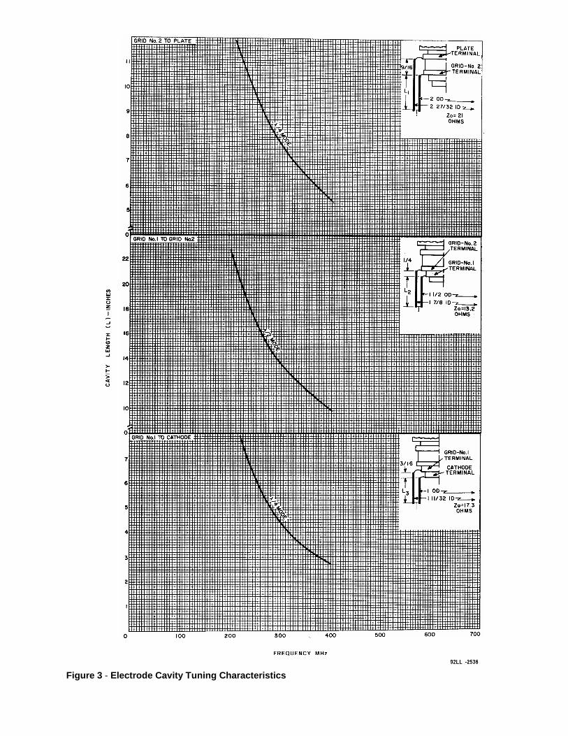
Figure 3 - Electrode Cavity Tuning Characteristics
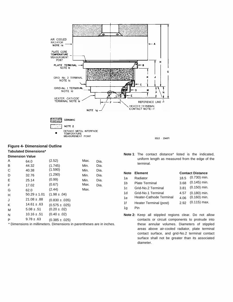
Figure 4- Dimensional OutlineTabulated Dimensions*Dimension ValueA 64.0 (2.52) Max. Dia.B 44.32 (1.745) Min. Dia.C 40.38 (1.590) Min. Dia.D 32.76 (1.290) Min. Dia.E 25.14 (0.99) Min. Dia.
F 17.02 (0.67) Max. Dia.G 62.0 (2.44) Max.
H 50.29 ± 1.01 (1.98 ± .04)
J 21.08 ± .88 (0.830 ± .035)K 14.61 ± .63 (0.575 ± .025)M 5.08 ± .51 (0.20 ± .02)
N 10.16 ± .51 (0.40 ± .02)
P 9.78 ± .63 (0.385 ± .025)* Dimensions in millimeters. Dimensions in parentheses are in inches.
Note 1: The contact distance* listed is the indicated,uniform length as measured from the edge of theterminal.
Note Element Contact Distance1a Radiator 18.5 (0.730) min.
1b Plate Terminal 3.68 (0.145) min.
1c Grid-No.2 Terminal 3.81 (0.150) min.
1d Grid-No.1 Terminal 4.57 (0.180) min.1e Heater-Cathode Terminal 4.06 (0.160) min.
1f Heater Terminal (post) 2.92 (0.115) max.
1g Pin
Note 2: Keep all stippled regions clear. Do not allowcontacts or circuit components to protrude intothese annular volumes. Diameters of stippledareas above air-cooled radiator, plate terminalcontact surface, and grid-No.2 terminal contactsurface shall not be greater than its associateddiameter.
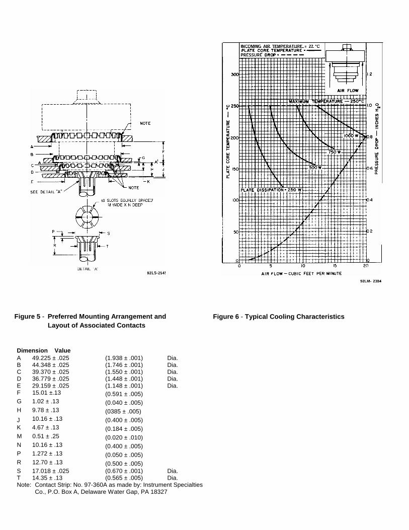
Dimension ValueA 49.225 ± .025 (1.938 ± .001) Dia.B 44.348 ± .025 (1.746 ± .001) Dia.C 39.370 ± .025 (1.550 ± .001) Dia.D 36.779 ± .025 (1.448 ± .001) Dia.E 29.159 ± .025 (1.148 ± .001) Dia.F 15.01 ±.13 (0.591 ± .005)G 1.02 ± .13 (0.040 ± .005)H 9.78 ± .13 (0385 ± .005)J 10.16 ± .13 (0.400 ± .005)K 4.67 ± .13 (0.184 ± .005)M 0.51 ± .25 (0.020 ± .010)N 10.16 ± .13 (0.400 ± .005)P 1.272 ± .13 (0.050 ± .005)R 12.70 ± .13 (0.500 ± .005)S 17.018 ± .025 (0.670 ± .001) Dia.T 14.35 ± .13 (0.565 ± .005) Dia.Note: Contact Strip: No. 97-360A as made by: Instrument Specialties
Co., P.O. Box A, Delaware Water Gap, PA 18327
Figure 5 - Preferred Mounting Arrangement andLayout of Associated Contacts
Figure 6 - Typical Cooling Characteristics