Embed Size (px)
Citation preview
06/04 01/1306/04 01/1301/05 05/1301/05 05/1303/07
748167 19220508 ŠKODA• Octavia II Limousine Saloon• Octavia II Combi Estate • Octavia II Scout
brink.eu
WiringkitEinbauanleitung
Installation instructions
Consignes de montage
Montagehandleiding
Montagevejledning
Monteringsinstruksjon
Installationsanvising
Asennusohje
Intruzioni per il montaggio
Instrucciones de montaje
Instuções de montagem
Οδηγίες εγκατάστασης
Návod k montáži
Navodilo za vgradnjo
Montážny návod
Instrukcja montazu
Montaj talimatı
Beépítési útmutató
Upute o ugradnji
инструкции за монтаж
Instrucțiuni de montaj
Инструкция по монтaжу и устaновке
Montavimo informacija
lemontešanas pamaciba
Paigaldusjuhend
D
GB
F
NL
DK
N
S
FIN
I
E
P
GR
CZ
SLO
SK
PL
TR
H
HR
BUL
RO
RU
LT
LV
EST
87220683 / 24.01.2017 / Subject to changes 1/12
07/14
87220683 / 24.01.2017 / Subject to changes 2/12
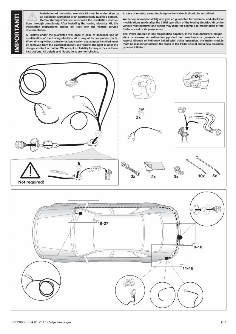
3x 10x 5x3x2x
15A
2x
19-27
11-16
3-10
Not required!
IMP
OR
TAN
T! In case of missing a rear fog lamp on the trailer, it should be retrofitted.
We accept no responsibility and give no guarantee for technical and electrical modifications made after the initial operation of the towing electrics kit by the vehicle manufacturer and which may lead, for example to malfunction of the trailer socket or its peripheries.
The trailer module is not diagnostics-capable. If the manufacturer’s diagno-stics processes or software-supported test mechanisms generate error reports directly or indirectly linked with trailer operation, the trailer module must be disconnected from the leads to the trailer socket and a new diagnstic process initiated.
Installation of the towing electrics kit must be undertaken by za specialist workshop or an appropriately qualified person. Before starting work, you must read the installation instruc-tions through completely. After installing the towing electrics kit, the installation instructions should be kept with the vehicle service documentation.
All claims under the guarantee will lapse in case of improper use or modification of the towing electrics kit or any of its component parts. When driving without a trailer or load carrier, any adapter installed must be removed from the electrical socket. We reserve the right to alter the design, content or colour. We accept no liability for any errors in these instructions. All details and illustrations are non-binding.
87220683 / 24.01.2017 / Subject to changes 3/12
1
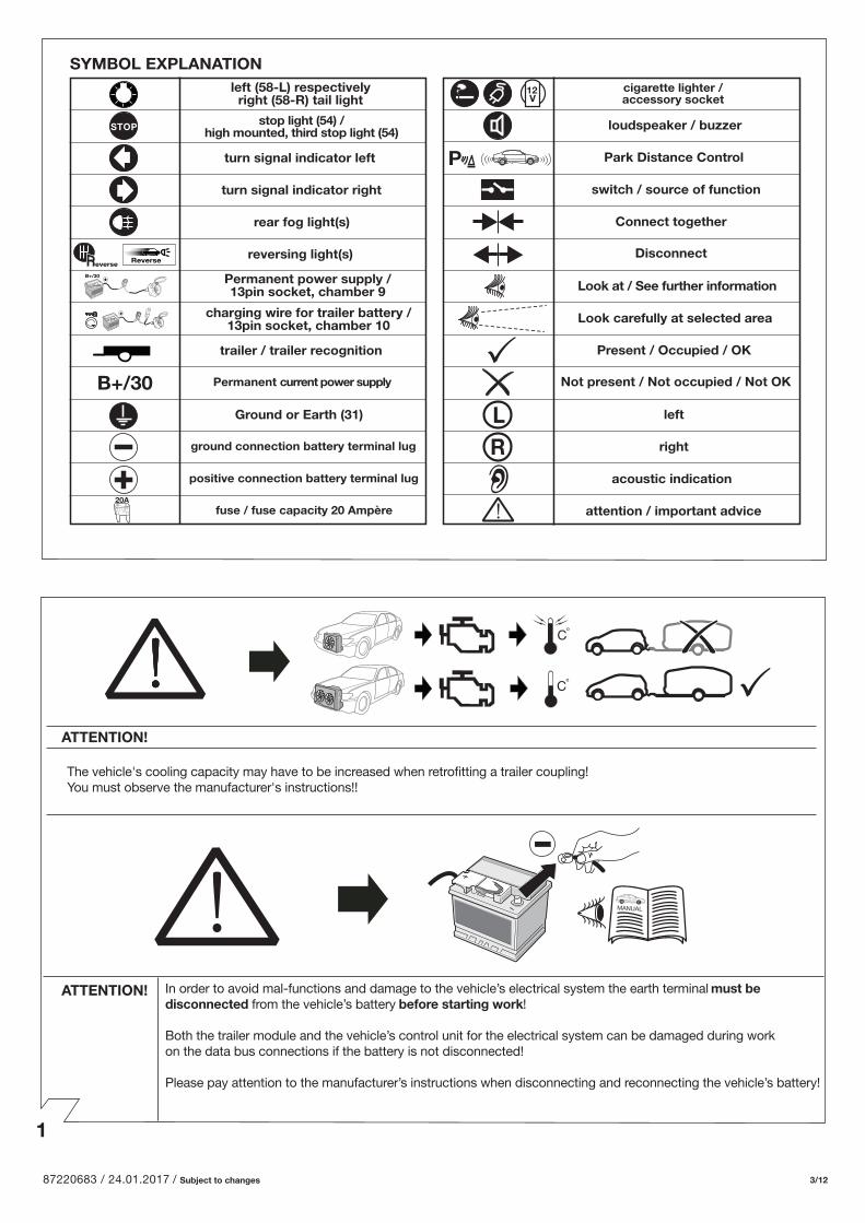
SYMBOL EXPLANATION
Reverse
B+/30
20A
left (58-L) respectively right (58-R) tail light
stop light (54) / high mounted, third stop light (54)
turn signal indicator left
turn signal indicator right
rear fog light(s)
reversing light(s)
trailer / trailer recognition
Permanent current power supply
Ground or Earth (31)
ground connection battery terminal lug
positive connection battery terminal lug
fuse / fuse capacity 20 Ampère
12V
P
cigarette lighter /accessory socket
loudspeaker / buzzer
Park Distance Control
switch / source of function
Connect together
Disconnect
Look at / See further information
Look carefully at selected area
Present / Occupied / OK
Not present / Not occupied / Not OK
left
right
acoustic indication
attention / important advice
B+/30 Permanent power supply / 13pin socket, chamber 9
charging wire for trailer battery / 13pin socket, chamber 10
everse
MANUAL
In order to avoid mal-functions and damage to the vehicle’s electrical system the earth terminal must be disconnected from the vehicle’s battery before starting work!
Both the trailer module and the vehicle’s control unit for the electrical system can be damaged during work on the data bus connections if the battery is not disconnected!
Please pay attention to the manufacturer’s instructions when disconnecting and reconnecting the vehicle’s battery!
The vehicle's cooling capacity may have to be increased when retrofitting a trailer coupling! You must observe the manufacturer's instructions!!
Co
Co
ATTENTION!
ATTENTION!
87220683 / 24.01.2017 / Subject to changes 4/12
2 3
4
5
6 7
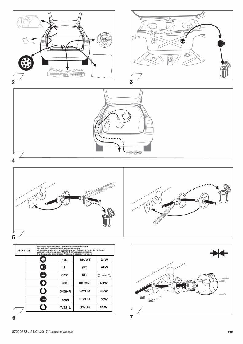
Belegung der Steckdose / Maximale AusgangsleistungSocket configuration / Maximum power outputCorrespondance des contacts de la prise / Puissance de sortie maximaleAbbinamento della presa / Uscita di alimentazione massimaIndeling van de stekkerdoos / maximaal uitgangsvermogen
ISO 1724
5/58-R
6/54
1/L
4/R
2
3/31
BK/WT
WT
BK/GN
BR
GY/RD
BK/RD
7/58-L GY/BK
21W
42W
21W
52W
63W
52W
87220683 / 24.01.2017 / Subject to changes 5/12
X00000000
ooooooooooooooooo
X00000000
ooooooooooooooooo
8
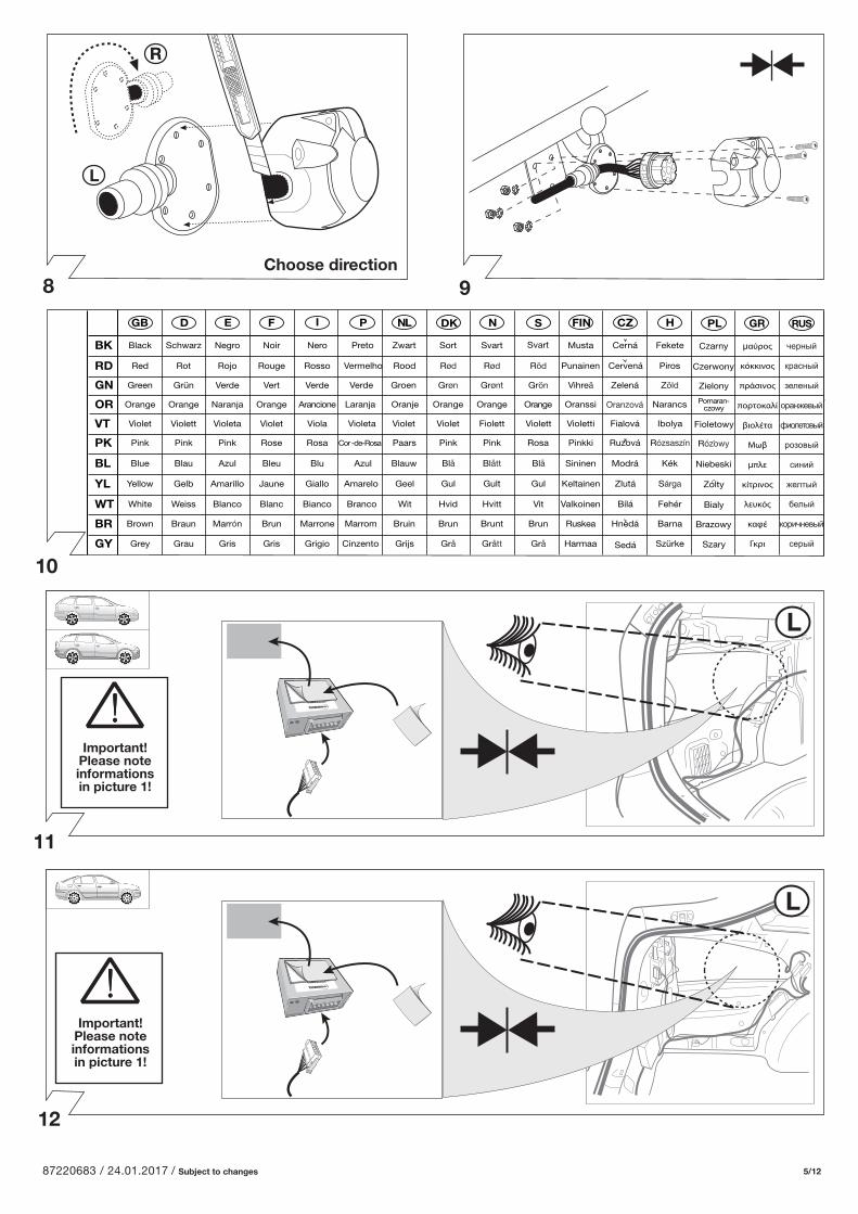
Important! Please note informations in picture 1!
Important! Please note informations in picture 1!
9
10
11
12
Choose direction
D FGB IE
Black Schwarz Negro Noir Nero
Red Rot Rojo Rouge Rosso
Green Grün Verde Vert Verde
Orange Orange Naranja Orange Arancione
Violet Violett Violeta Violet Viola
Pink Pink Pink Rose Rosa
Blue Blau Azul Bleu Blu
Yellow Gelb Amarillo Jaune Giallo
White Weiss Blanco Blanc Bianco
Brown Braun Marrón Brun Marrone
Grey Grau Gris Gris Grigio
NL NP SDK
Preto Zwart Sort Svart
Vermelho Rood Rød Rød Röd
Verde Groen Grøn Grønt Grön
Laranja Oranje Orange Orange Orange
Violeta Violet Violet Fiolett Violett
Cor-de-Rosa Paars Pink Pink Rosa
Azul Blauw Blå Blått Blå
Amarelo Geel Gul Gult Gul
Branco Wit Hvid Hvitt Vit
Marrom Bruin Brun Brunt Brun
Cinzento Grijs Grå Grått Grå
CZFIN H
Musta Cerná Fekete
Punainen Cervená Piros
Vihreä Zelená Zöld
Oranssi Narancs
Violetti Fialová Ibolya
Pinkki Ruzová Rózsaszín
Sininen Modrá Kék
Keltainen Zlutá Sárga
Valkoinen Bílá Fehér
Ruskea Hnedá Barna
Harmaa Sedá Szürke
PL GR RUS
Czarny µαύρος
κόκκινος
πράσινος
πορτοκαλί
βιολέτα
Μωβ
µπλε
κίτρινος
λευκός
καφέ
Γκρι
черный
красный
зеленый
оранжевый
фиолетовый
розовый
синий
желтый
белый
коричневый
серый
Czerwony
Zielony
Pomaran-czowy
Fioletowy
Rózowy
Niebeski
Zólty
Bialy
Brazowy
Szary
Svart
Oranzová
RD
BK
GN
OR
VT
PK
BL
YL
WT
BR
GY
87220683 / 24.01.2017 / Subject to changes 6/12
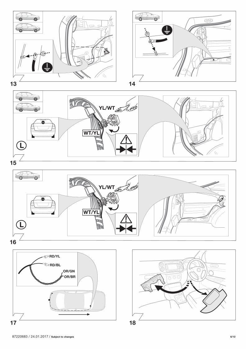
YL/WT
YL/WT
WT/YL
WT/YL
OR/GN
OR/BR
RD/YL
RD/BL
13 14
15
16
17 18
87220683 / 24.01.2017 / Subject to changes 7/12
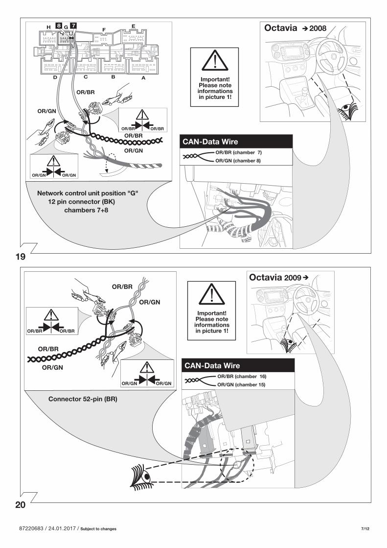
Octavia 2009 OR/BR
OR/BR
OR/GN
OR/GN
Important! Please note informations in picture 1!
Important! Please note informations in picture 1!
OR/BR (chamber 16)
OR/GN (chamber 15)
OR/BROR/BR
OR/GNOR/GN
19
20
OR/BR
OR/BR
OR/GN
OR/GN
Octavia 2008
OR/BR OR/BR
OR/GN OR/GN
Network control unit position "G" 12 pin connector (BK)
chambers 7+8
H G
D C B A
EF
OR/BR (chamber 7)
OR/GN (chamber 8)
CAN-Data Wire
CAN-Data Wire
Connector 52-pin (BR)
87220683 / 24.01.2017 / Subject to changes 8/12
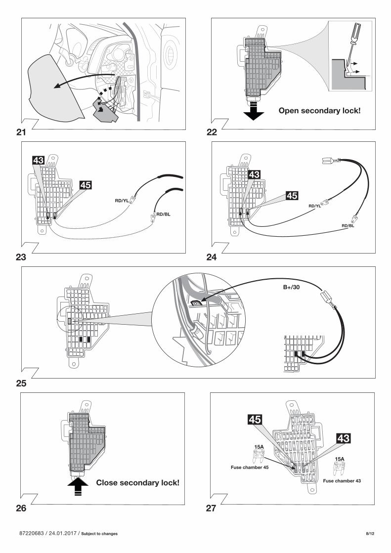
Open secondary lock!
21 22
23 24
25
26 27
Close secondary lock!
45
RD/YL
RD/BL
43
45RD/YL
RD/BL
43
B+/30
15A
Fuse chamber 45
45
43
15A
Fuse chamber 43
87220683 / 24.01.2017 / Subject to changes 9/12
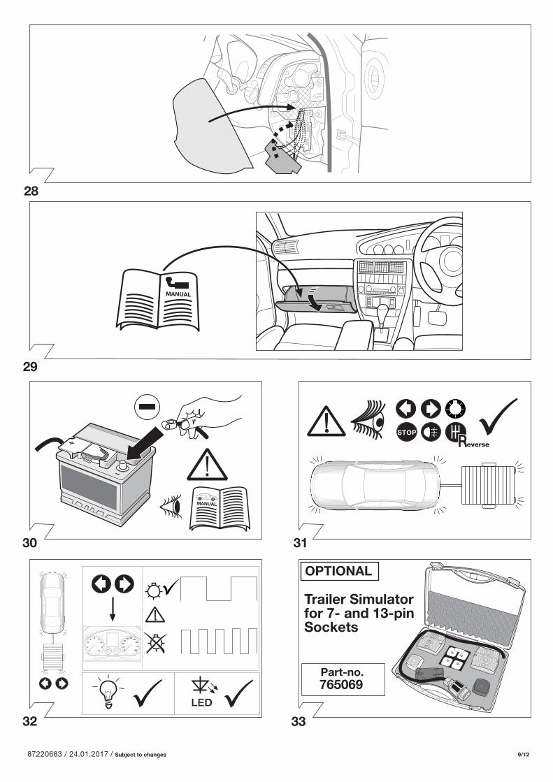
everse
MANUAL
OPTIONAL
Part-no.765069
Trailer Simulatorfor 7- and 13-pinSockets
Permanent power supply
Charging wire for trailer battery
Dauerstrom
Ladeleitung
everse
PIN 9
PIN 10
28
29
32
30
33
31
MANUAL
LED
87220683 / 24.01.2017 / Subject to changes 10/12
35
34
36
37
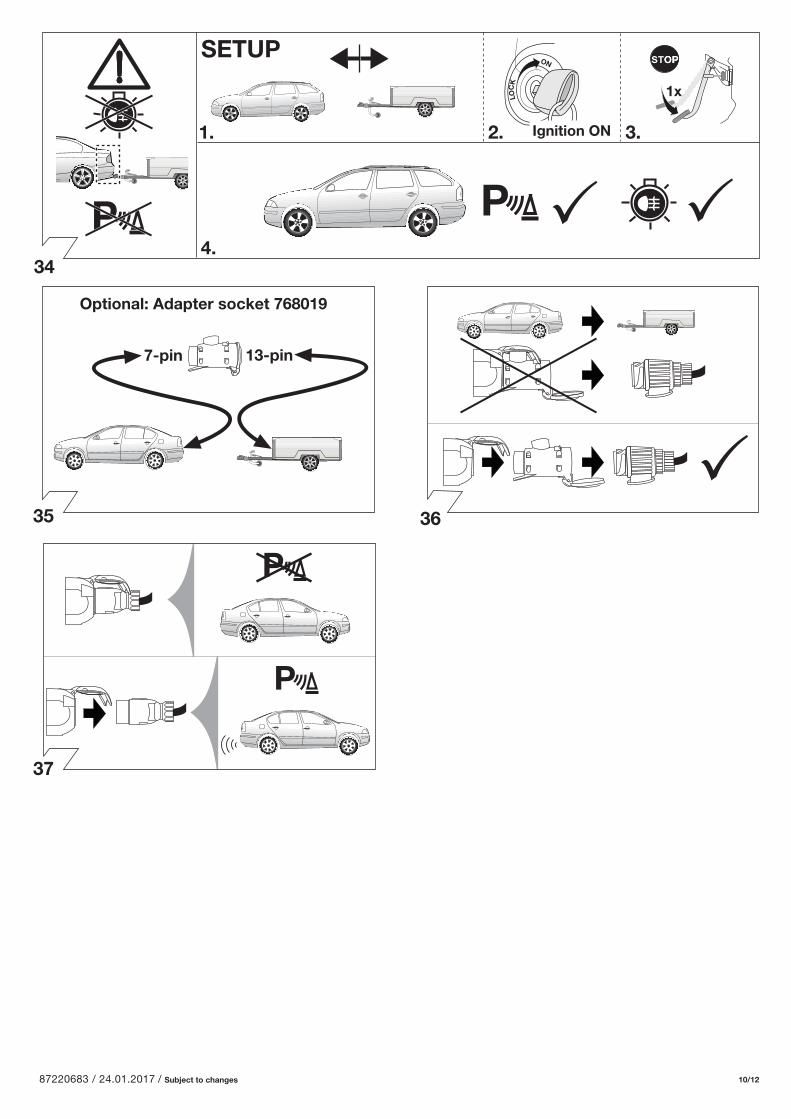
SETUP
1x
P
1. 2. 3.
4.
ON
LOC
K
Ignition ON
P
P
P
13-pin7-pin
Optional: Adapter socket 768019
87220683 / 24.01.2017 / Subject to changes 11/12
39
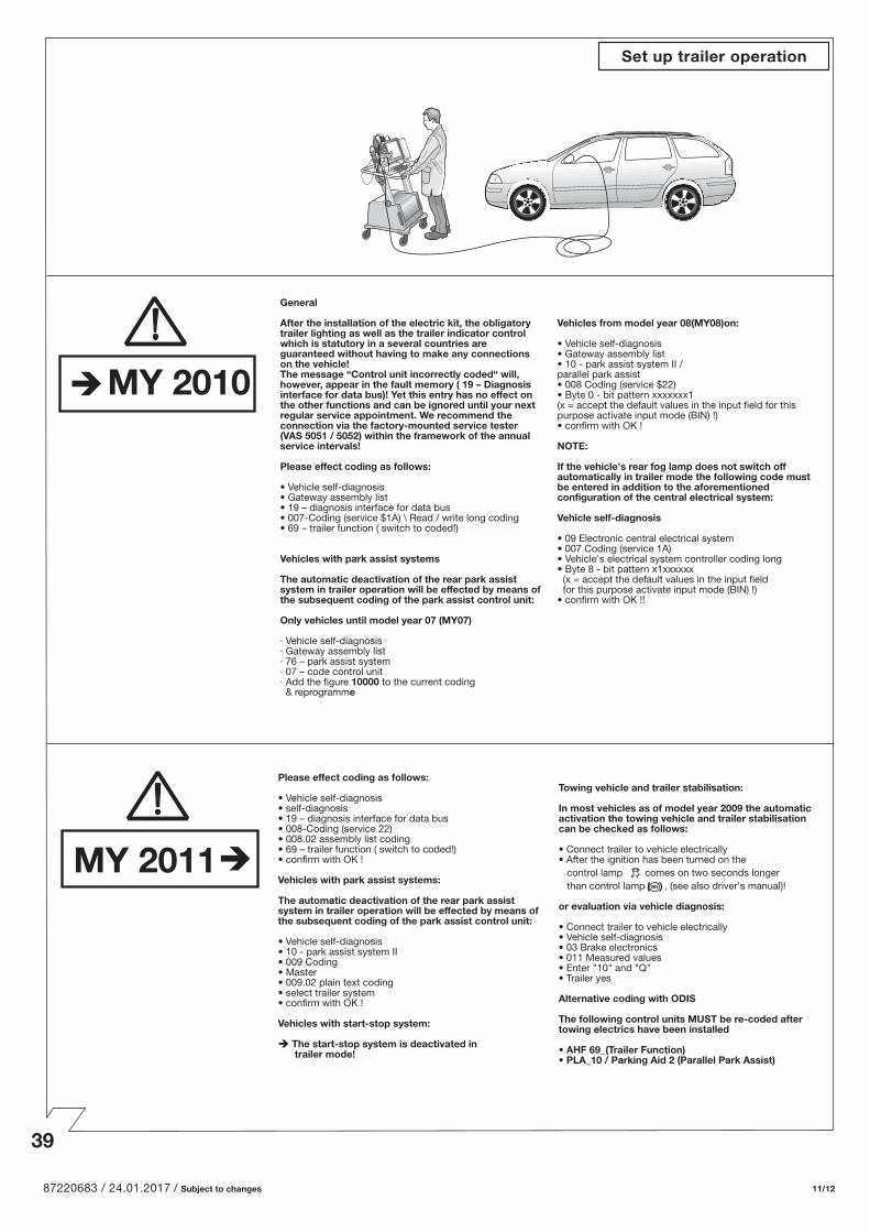
General
After the installation of the electric kit, the obligatory trailer lighting as well as the trailer indicator control which is statutory in a several countries are guaranteed without having to make any connections on the vehicle! The message “Control unit incorrectly coded“ will, however, appear in the fault memory ( 19 – Diagnosis interface for data bus)! Yet this entry has no e�ect on the other functions and can be ignored until your next regular service appointment. We recommend the connection via the factory-mounted service tester (VAS 5051 / 5052) within the framework of the annual service intervals!
Please e�ect coding as follows:
• Vehicle self-diagnosis • Gateway assembly list• 19 – diagnosis interface for data bus• 007-Coding (service $1A) \ Read / write long coding• 69 – trailer function ( switch to coded!)
Vehicles with park assist systems
The automatic deactivation of the rear park assist system in trailer operation will be e�ected by means of the subsequent coding of the park assist control unit:
Only vehicles until model year 07 (MY07)
· Vehicle self-diagnosis· Gateway assembly list· 76 – park assist system· 07 – code control unit· Add the figure 10000 to the current coding & reprogramme
Vehicles from model year 08(MY08)on:
• Vehicle self-diagnosis• Gateway assembly list• 10 - park assist system II / parallel park assist• 008 Coding (service $22)• Byte 0 - bit pattern xxxxxxx1(x = accept the default values in the input field for this purpose activate input mode (BIN) !)• confirm with OK !
NOTE:
If the vehicle's rear fog lamp does not switch o� automatically in trailer mode the following code must be entered in addition to the aforementioned configuration of the central electrical system:
Vehicle self-diagnosis
• 09 Electronic central electrical system• 007 Coding (service 1A)• Vehicle's electrical system controller coding long • Byte 8 - bit pattern x1xxxxxx (x = accept the default values in the input field for this purpose activate input mode (BIN) !)• confirm with OK !!
Set up trailer operation
MY 2010
Please e�ect coding as follows:
• Vehicle self-diagnosis• self-diagnosis • 19 – diagnosis interface for data bus• 008-Coding (service 22)• 008.02 assembly list coding• 69 – trailer function ( switch to coded!)• confirm with OK !
Vehicles with park assist systems:
The automatic deactivation of the rear park assist system in trailer operation will be e�ected by means of the subsequent coding of the park assist control unit:
• Vehicle self-diagnosis• 10 - park assist system II • 009 Coding• Master• 009.02 plain text coding• select trailer system• confirm with OK !
Vehicles with start-stop system:
The start-stop system is deactivated in trailer mode!
Towing vehicle and trailer stabilisation: In most vehicles as of model year 2009 the automaticactivation the towing vehicle and trailer stabilisationcan be checked as follows:
• Connect trailer to vehicle electrically • After the ignition has been turned on the control lamp comes on two seconds longer than control lamp , (see also driver's manual)!
or evaluation via vehicle diagnosis:
• Connect trailer to vehicle electrically • Vehicle self-diagnosis• 03 Brake electronics• 011 Measured values • Enter "10" and "Q" • Trailer yes
Alternative coding with ODIS
The following control units MUST be re-coded after towing electrics have been installed • AHF 69_(Trailer Function)• PLA_10 / Parking Aid 2 (Parallel Park Assist)
MY 2011
87220683 / 24.01.2017 / Subject to changes 12/12
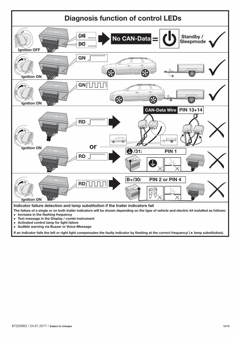
Diagnosis function of control LEDs
ON
LOC
K
Ignition ON
ON
LOC
K
Ignition ON
ON
LOC
K
Ignition ON
RD
orRD
RD
No CAN-Data Standby /Sleepmode=
B+/30: PIN 2 or PIN 4
/31: PIN 1
OFF
Ignition OFF
ON
LOC
K
Ignition ON
GN
RD
GN
GN
CAN-Data Wire PIN 13+14
Indicator failure detection and lamp substitution if the trailer indicators failThe failure of a single or on both trailer indicators will be shown depending on the type of vehicle and electric kit installed as follows: Increase in the flashing frequency Text message in the Display / combi-instrument Activated control lamp for light failure Audible warning via Buzzer or Voice-Message
If an indicator fails the left or right light compensates the faulty indicator by flashing at the correct frequency! ( lamp substitution).