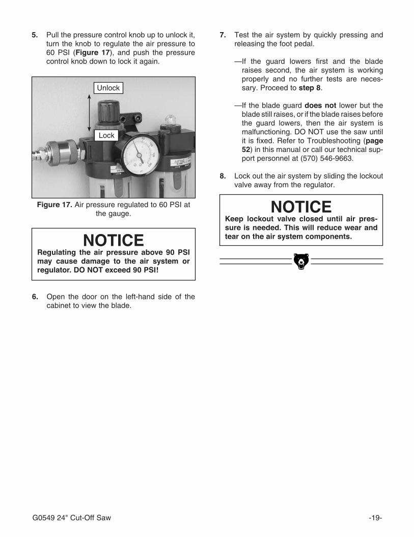
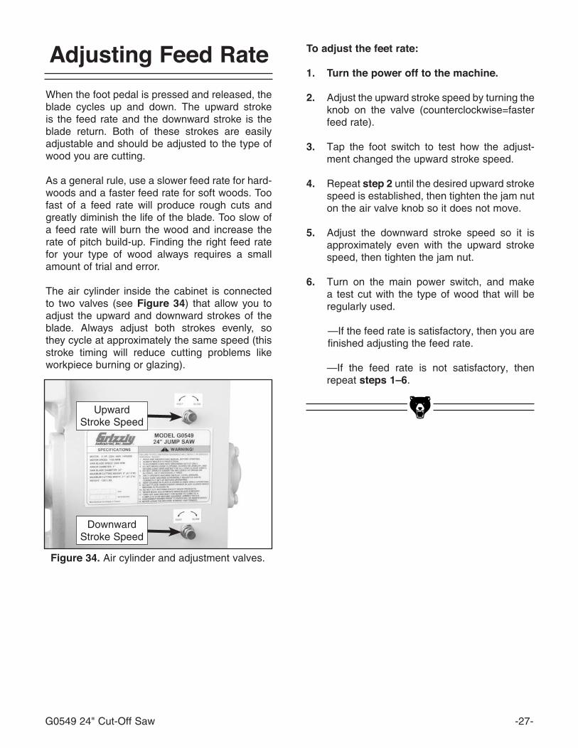
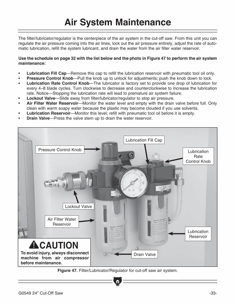
Embed Size (px)
Citation preview


Copyright © FEBrUAry, 2009 By grizzly indUstriAl, inC.Warning: no portion of this manual may be reproduced in any shape
or form Without the Written approval of grizzly industrial, inc. #ts11589 printEd in tAiwAn
the Model g0549 Jump saw has changed from when the manual was originally written. we have added a limit switch for the glade guard hood and a guard over the foot pedal. the 440V conversion information has also been updated. the new parts breakdowns, parts lists, wiring diagrams, and 440V conversion instruc-tions are included in this update.
Before operating your new machine, you MUst read and understand this manual update And the original manual to reduce the risk of injury from improper use or setup. pay special attention to the warning informa-tion included below regarding the blade guard.
If you need additional help with any of these procedures, contact our Tech Support at (570) 546-9663 or by email at [email protected].
model g054924" Jump saWmanual update
(for machines manufacturedafter march, 2008)
in addition to the safety instructions in your owner's manual for this machine, follow these rules regarding the blade guard hood and clamping blade guard:
• ALWAYSdisconnectpower to themachineBEFOREmakingadjustments to theclampingbladeguardtoavoidtheriskofunexpectedstartup,whichcouldresultinseriouspersonalinjury.
• ALWAYSproperlyadjust theclampingbladeguard for theworkpiece thicknessso that itoperates safely and efficiently.
• Theclampingbladeguardmovesdownwithgreatforceandcaneasilycrushyourhands.ALWAYSkeepyourhandsandbodypartsaway from thisguardbeforepressing the footpedal.
• NEVERhavethemachineconnectedtopowerwhenthegladeguardhoodisremoved.
• DONOTmodifythegladeguardhoodorclampingbladeguard.DONOTinterferewiththeiroperation in any way.
Blade guard hood
Clamping Blade guard
-2- g0549 Manual Update
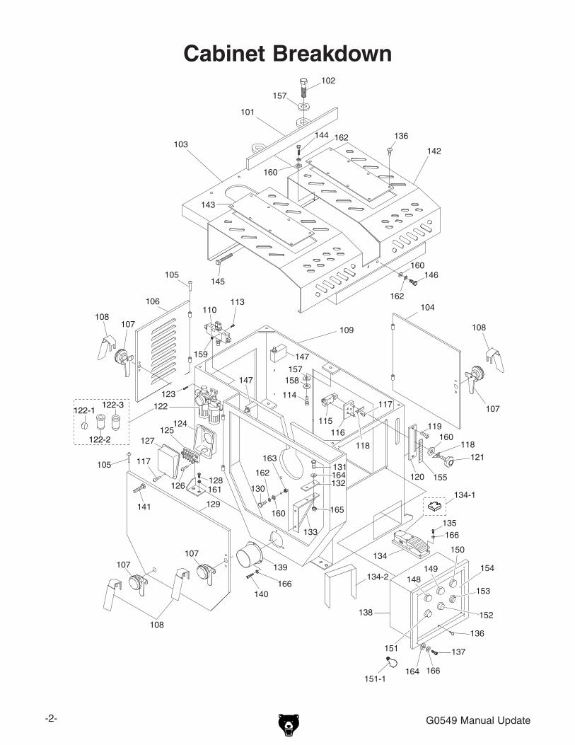
CabinetBreakdown
127
117105
107
140
129
122
124
126
125
130
139
106
107
105
120
138
132
133
114
115
131
116
137
135
119
104
109
142103
101
147
102
108
145
136
146
110113
123
141
128
108136
134
134-1
117
107
107
157
108
158157
160
121
161
162
160
163
165
164
166
166164
166
162
160
159
118
143
144 162
160
148149
150
151
152
153
154
155
118
122-1122-3
122-2
147
134-2
151-1

g0549 Manual Update -3-
cabinet parts listREF PART # DESCRIPTION REF PART # DESCRIPTION101 P0549101 FENCE 134-1 P0549134-1 PEDAL CONTROLLER102 PB75M HEX BOLT M12-1.75 X 35 134-2 P0549134-2 PEDAL GUARD103 P0549103 TABLE 135 PB18M HEX BOLT M6-1 X 15104 P0549104 RIGHT SIDE DOOR 136 PS38M PHLP HD SCR M4-.7 X 10105 P0549105 HINGE PIN 137 PB10M HEX BOLT M6-1 X 25106 P0549106 REAR DOOR 138 P0549138 CONTROL BOX ASSEMBLY107 P0549107 SAFETY LOCK 139 P0549139 DUST PORT108 P0549108 SAFETY LOCK HANDLE 140 PSB28M CAP SCREW M6-1 X 15109 P0549109 CABINET 141 P0549141 SPECIAL BOLT M10-1.5 X 130110 P0549110 AIR VALVE 142 P0549142 BLADE GUARD HOOD113 PS65M PHLP HD SCR M4-.7 X 40 143 P0549143 ACRYLIC PLATE114 PB27M HEX BOLT M12-1.75 X 30 144 PB09M HEX BOLT M8-1.25 X 20115 P0549115 LIMIT SWITCH 145 PB89 HEX BOLT 1/2-12 X 4-1/2116 P0549116 LIMIT SWITCH PLATE 146 PB09M HEX BOLT M8-1.25 X 20117 PS06 PHLP HD SCR 10-24 X 3/8 147 P0549147 LIMIT SWITCH118 P0549118 ELEVATION POINTER 148 P0549148 AIR INLET SWITCH119 PSB28M CAP SCREW M6-1 X 15 149 P0549149 AIR E-STOP BUTTON120 P0549120 ELEVATION LOCK PLATE 150 P0549150 MANUAL SWITCH121 P0549121 LOCK KNOB M8-1.25 X 30 151 P0549151 POWER SOURCE LIGHT122 P0549122 FILTER/LUBRICATOR/REGULATOR 151-1 P0549151-1 BULB 220V122-1 P0549122-1 GAUGE 152 P0549152 SAW START BUTTON122-2 P0549122-2 OIL CUP 153 P0549153 SAW STOP BUTTON122-3 P0549122-3 WATER CUP 154 P0549154 PANEL123 PSB02M CAP SCREW M6-1 X 20 155 P0549155 SCALE124 P0549124 TERMINAL BOX BASE 157 PW06M FLAT WASHER 12MM125 P0549125 TERMINAL BLOCK 158 PLW05M LOCK WASHER 12MM126 PS03 PHLP HD SCR 10-24 X 1 159 PN04M HEX NUT M4-.7127 P0549127 TERMINAL BOX COVER 160 PW01M FLAT WASHER 8MM128 PB51M HEX BOLT M16-2 X 50 161 PN13M HEX NUT M16-2129 P0549129 LEFT SIDE DOOR 162 PLW04M LOCK WASHER 8MM130 PB118M HEX BOLT M8-1.25 X 45 163 PN03M HEX NUT M8-1.25131 PB47M HEX BOLT M6-1 X 40 164 PW03M FLAT WASHER 6MM132 P0549132 RUBBER PAD 165 PN01M HEX NUT M6-1133 P0549133 SPINDLE SUPPORT BRACKET 166 PLW03M LOCK WASHER 6MM134 P0549134 PEDAL SWITCH

-4- g0549 Manual Update
HeadBreakdown
REF PART # DESCRIPTION REF PART # DESCRIPTION201 P0549201 HEAD COVER 220 P0549220 SUPPORT CRANK202 PUCF205 BALL BEARING UCF205 221 P0549221 UPPER DUST HOOD203 PB24 HEX BOLT 3/8-16 X 1-1/4 222 P0549222 ADJUSTABLE PLATE204 P0549204 ADJUSTABLE AIR VALVE 223 PB71M HEX BOLT M6-1 X 45205 PFH38M FLAT HD SCR M6-1 X 16 224 P0549224 WING BOLT M6-1 X 12206 P0549206 CLAMPING BLADE GUARD 225 P0549225 RUBBER PLATE207 P0549207 REAR SAFETY COVER 226 PFH03M FLAT HD SCR M6-1 X 40208 PB118M HEX BOLT M8-1.25 X 45 227 P0549227 BAKELITE INSERT209 PS68M PHLP HD SCR M6-1 X 10 228 P0549228 GREASE FITTING 1/16 X 90 DEG210 P0549210 HEAD REAR COVER 229 PSS02M SET SCREW M6-1 X 6211 PB27M HEX BOLT M12-1.75 X 30 230 P0549230 ADJUSTMENT KNOB 3/4-10212 P0549212 SUPPORT ARM SHAFT 231 PSS16M SET SCREW M8-1.25 X 10213 P0549213 SQUARE BRACKET 232 PN17 HEX NUT 3/4"-10214 PSB14 CAP SCREW 3/8-16 X 1 233 P0549233 STUD 3/4-10 X 6"215 P6206 BALL BEARING 6206ZZ 234 PLW04 LOCK WASHER 3/8216 PB53 HEX BOLT 1/2-12 X 1 235 PLW04M LOCK WASHER 8MM217 P0549217 FENDER WASHER 1/2 236 PLW05M LOCK WASHER 12MM218 P0549218 MAIN CRANK 237 PW03M FLAT WASHER 6MM219 P0549219 GREASE FITTING 1/8 X 45 DEG 238 PN01M HEX NUT M6-1
217216
219219
203
232
231
226
222
224
211
236
234
237237
238
238235
227
228
229
223 221
225
226
205
215
216217
210
209
216
217
220
219
217
218
214
213
212
216
233
208
206
207
230
202
201
204
g0549 Manual Update -5-
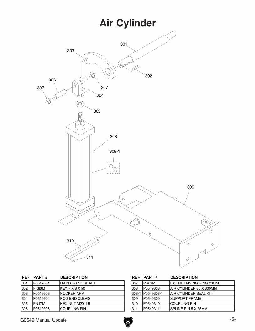
air cylinder
REF PART # DESCRIPTION REF PART # DESCRIPTION301 P0549301 MAIN CRANK SHAFT 307 PR09M EXT RETAINING RING 20MM302 PK86M KEY 7 X 8 X 50 308 P0549308 AIR CYLINDER 80 X 300MM303 P0549303 ROCKER ARM 308-1 P0549308-1 AIR CYLINDER SEAL KIT304 P0549304 ROD END CLEVIS 309 P0549309 SUPPORT FRAME305 PN17M HEX NUT M20-1.5 310 P0549310 COUPLING PIN306 P0549306 COUPLING PIN 311 P0549311 SPLINE PIN 5 X 35MM
307 307
305
309
311
310
303
306
308
304
301
302
308-1

-6- g0549 Manual Update
motor
REF PART # DESCRIPTION REF PART # DESCRIPTION401 PB33M HEX BOLT M12-1.75 X 50 411-1 P0549411-1 MOTOR FAN COVER402 P0549402 TABLE BRACKET 411-2 P0549411-2 MOTOR FAN403 P6205 BALL BEARING 6205ZZ 411-3 P0549411-3 MOTOR WIRING JUNCTION BOX404 PN13M HEX NUT M16-2 412 PK87M KEY 10 X 8 X 80405 PW08M FLAT WASHER 16MM 413 P0549413 MOTOR PULLEY406 P0549406 MOTOR MOUNT BAR M12-1.75 414 PSS13M SET SCREW M10-1.5 X 12407 PN09M HEX NUT M12-1.75 415 P0549415 V-BELT MF6500408 P0549408 MOTOR SCREW M16-2 X 150 416 PLW05M LOCK WASHER 12MM409 P0549409 MOTOR PLATE 417 PLW06M LOCK WASHER 10MM410 PB01M HEX BOLT M10-1.5 X 30 418 PW04M FLAT WASHER 10MM411 P0549411 MOTOR 15HP 220/440V 3PH 60HZ
401
418
402
407
403416
404405
412
409
407
408
406
404
405
413
411
404414
405
415
402
403
417
410
404
405
416
416
401
416
411-2
411-1411-3

g0549 Manual Update -7-
blade assembly
REF PART # DESCRIPTION REF PART # DESCRIPTION501 P0549501 ARBOR WRENCH 513 P0549513 LIMIT SWITCH DOG502 P0549502 ARBOR NUT 1-12 514 PB07M HEX BOLT M8-1.25 X 25503 P0549503 BLADE 24 X 1 X 80T X 0.16 515 P0549515 SPINDLE SHAFT504 P0549504 OUTSIDE ARBOR FLANGE 516 PK86M KEY 7 X 8 X 50505 P0549505 INSIDE ARBOR FLANGE 517 P0549517 SPANNER NUT (LH) M35-16506 P0549506 FRONT END CAP 518 P0549518 REAR END CAP507 PSB02M CAP SCREW M6-1 X 20 519 P0549519 ARBOR PULLEY508 P6207 BALL BEARING 6207ZZ 520 PSS75M SET SCREW M10-1.5 X 16509 P0549509 SPINDLE HOUSING 521 PLW05M LOCK WASHER 12MM510 PSB92M CAP SCREW M12-1.75 X 40 522 PLW04M LOCK WASHER 8MM511 P0549511 TAPER PIN 4 X 40MM 523 PW01M FLAT WASHER 8MM512 P0549512 GREASE FITTING 1/4
508
502
515
501 516
504
503
507
511
505
517518
507
519
512
508506
509
513
514
510
520
521
522523

-8- g0549 Manual Update
roller tables
REF PART # DESCRIPTION REF PART # DESCRIPTION600A P0549600A LEFT & RIGHT ROLLER TABLE ASSY 607 PB07M HEX BOLT M8-1.25 X 25601 P0549601 BRACKET 608 P0549608 LOCK HANDLE M8-1.25 X 20602 P0549602 LEFT ROLLER TABLE ASSEMBLY 609 P0502025 QUICK STOP602-1 P0549602-1 INDIVIDUAL ROLLER 610 P0549610 FIXED STOP602A P0549602A RIGHT ROLLER TABLE ASSEMBLY 611 P0549611 SPECIAL FLAT WASHER 8MM603 P0549603 STAND 612 P0549612 SQUARE RAIL604 P0549604 ADJUSTMENT FOOT 5/8-11 X 4 613 P0549613 SCALE605 PB09M HEX BOLT M8-1.25 X 20 614 PSB13M CAP SCREW M8-1.25 X 30606 PW01M FLAT WASHER 8MM
602 – LEFT ROLLERTABLE ASSEMBLY
605
606
612614
611
610609
608
608
606
605
601
607606
613
604
603
602A – RIGHT ROLLERTABLE ASSEMBLY
605
606
601
606
607
606
605
603
604
602-1
600A

g0549 Manual Update -9-
electrical panel
10 2
R S TU1 V1 W1 Z1 X1 Y1
1T1R1
R T R27 6
5 5
98R S T5R S T
5 9 8
10 10 10 10
U1 V1 W1 4 Z1 X1 Y1 6 Z1 X1 Y1 7
KM1DC-25D10
KM1DC-25D01
KM1SC-18D01
KT1H3-30S
FU1 FU2 FU3
FR1NTH-25
HM
M4
HM
M4
HM
M4
HM
M4
HM
M4
HM
M4
CB
D10
CB
D10
CB
D10
PE 220V 440V 380V 220V0V 0V
T1R1R22
PE
Transformer
701 702 703 704 705
706
717
707
708 709 710
711 712
713
714
715
716
440V Rewire Kit
11
HM
M2
1 12
HM
M2
HM
M2
10 2
FR1NTH-14
REF PART # DESCRIPTION701 P0549701 CONTACTOR KM1M C-25D 220V NHD702 P0549702 CONTACTOR KM1D C-25D 220V NHD703 P0549703 CONTACTOR KM1S C-18D01 220V704 P0549704 TIMER KT1 H3-30S705 P0549705 FUSE 5 AMP706 P0549706 OL RELAY NHD NTH-25 21-25 220V707 P0549707 TERMINAL STRIP PE X 6708 P0549708 MODULAR TERMINAL CBD10709 P0549709 MODULAR TERMINAL HMM4710 P0549710 MODULAR TERMINAL HMM2711 P0549711 MODULAR TERMINAL BASE712 P0549712 TRANSFORMER TC1713 P0549713 WIRE LOOM & COVER 25 X 230714 P0549714 WIRE LOOM & COVER 25 X 190715 P0549715 WIRE LOOM & COVER 25 X 160716 P0549716 WIRE LOOM & COVER 25 X 130717 P0549717 440V CONVERSION KIT 11/14A NHD

-10- g0549 Manual Update
label placement
Safetylabelswarnaboutmachinehazardsandwaystopreventinjury.Theownerofthismachinemust maintain the original location and readability of the labels on the machine. if any label is removed or becomes unreadable, replace that label before using the machine again. contact grizzly at (800) 523-4777 or www.grizzly.com to order new labels.
REF PART # DESCRIPTION REF PART # DESCRIPTION615 PLABEL-12 READ MANUAL LABEL 621 P0549621 MACHINE ID LABEL616 PLABEL-11 SAFETY GLASSES LABEL 622 P0549622 CUTTING HAZARD LABEL617 PLABEL-36 DISCONNECT POWER-DOOR LABEL 623 P0549623 SAFETY GUARD LABEL618 P0549618 HANDS UNDER GUARD LABEL 624 PPAINT-1 GRIZZLY GREEN TOUCH-UP PAINT619 PLABEL-14 ELECTRICITY LABEL 625 PPAINT-11 GRIZZLY PUTTY TOUCH-UP PAINT620 PLABEL-30 CLOSE DOOR LABEL
615
616
617
618
619
620
621
622
623
624
625
622
620

g0549 Manual Update -11-
Wiring diagram
11
HM
M2
Power Source
Air Inlet Switch Air Emergency Stop Button
Saw Start ButtonSaw Stop Button
Manual Switch
220V440V
440V
11
3
5 5
4 2
1
2
3
4
10 2
R S TU1 V1 W1 Z1 X1 Y1
1 12
1T1R1
R T R27 6
5 5
98R S T5R S T
5 9 8
10 10 10 10
U1 V1 W1 4 Z1 X1 Y1 6 Z1 X1 Y1 7
KM1MC-25D10
KM1DC-25D01
KM1SC-18D01
KT1H3-30S
FU1 FU2 FU3
NTH-25 (220V)
NTH-12 (440V)
HM
M2
HM
M4
HM
M4
HM
M4
HM
M4
HM
M4
HM
M4
CB
D10
CB
D10
CB
D10
HM
M2
PE 220V 440V 380V 220V0V 0V
T1R1R22
PE
Transformer
W6 U6 V6
X1 Y1 Z1
W2 U2 V2
U5 V5 W5
U1 V1 W1
U1 V1 W1
W6 U6 V6
X1 Y1 Z1
U2 V2 W2
U5 V5 W5
U1 V1 W1
U1 V1 W1
ClosedOpen
NormallyCommon
ClosedOpen
NormallyCommon
Safety GuardLimit Switch
Door SafetyLimit Switch

-12- g0549 Manual Update
440v conversion
the Model g0549 can be converted for 440V 3-phase operation. the procedure consists of changing the overload relay, and rewiring the transformer and motor.
order the Model g0549 440V Conversion Kit (p/n p0549717) by calling our Customer service at (800) 523-4777.
the 440v conversion procedure requires moderateelectricalskillandknowledge,andthe rewiring must be inspected by a licensed electrician before the saw is connected to power.Heedthiswarningtoavoidtheriskofserious personal injury from electrocutionor damage to the saw.
to convert the model g0549 for 440v opera-tion:
1. disConnECt sAw FroM powEr!
2. open the electrical panel, then replace the overload relay with the one from the 440V conversion kit (see figure 4).
3. Move the wire that is connected to the r1 terminal on the transformer to the one above the 440V terminal, as illustrated in figure 5.
440V
PE 220V 440V 380V 220V0V 0V
T1R1R22
Transformer
figure 5. rewiring the transform for 440V operation.
4. Make sure the trip load dial of the overload relay is set at 12 amps (see figure 4).
5. wire the motor as shown on the inside of the motor wiring junction box cover for 440V operation.
note: The illustration in Figure 6 is provided for your reference and was current at the time that this manual update was printed. However, always use the diagram on the wir-ing junction box cover that comes with your motor.
W6 U6 V6
X1 Y1 Z1
U2 V2 W2
U5 V5 W5
U1 V1 W1
U1 V1 W1
figure 6. Model g0549 motor wiring for 440V operation.
figure 4. Model g0549 overload relay inside the electrical panel.
overloadrelay
trip load dial

New Blade GuardWe improved the blade guard by installing a stake-type guard on the infeed side and one-way hinged guard flaps on the outfeed side.
MODEL G054924" CUT-OFF SAW
MANUAL UpDATE
Copyright © MArCh, 2010 By grizzly industriAl, inC. rEVisEd April, 2010 (JB)WArNiNG: NO pOrTiON OF ThiS MANUAL MAy BE rEprODUCED iN ANy ShApE
Or FOrM WiThOUT ThE WriTTEN ApprOvAL OF GrizzLy iNDUSTriAL, iNC.(For ModEls MAnuFACturEd sinCE 4/10) #JB12659 printEd in usA
this machine has changed slightly from when the manual was originally written. it now includes a deluxe blade guard, a workpiece holding mechanism, and dual start buttons to prevent access to the blade during operations. this update includes instructions for setting up the guard before each use and operating the machine with its new components, and a parts breakdown and list for the new components.
Before operating the machine, you Must read and understand this manual update And the original manual to reduce the risk of injury from improper use or setup. since this update covers changes made to the machine after the owner's manual was printed, you Must keep this update with your owner's manual for future reference. If you have questions, contact Tech Support at (570) 546-9663 or by email at [email protected].
To prepare the blade guard for operation:
1. place the workpiece on the machine against the fence and approximately 1" away from the guard.
2. For each guard stake, loosen the wing screw, then adjust the height approximately 1" above the stock you plan to cut. this will allow ade-quate clearance for inserting the stock but help keep fingers or hands out of the cutting area.
Note: The two guard stakes above the workpiece holding mechanism must be left high enough to not interfere with the mecha-nism during operation.
OperationWhen properly assembled, the changes to the machine help keep hands away from the blade during operation; however, this requires different procedures from those described in the Model g0549 owner's manual.
To operate the G0549:
1. perform Steps 1–3 on page 25 of the Model g0549 manual to prepare the machine and stock for operation. Make sure to place the end of the stock firmly against the stop and the side of the stock against the fence.
2. press the stArt button on the control panel to turn the motor ON, then allow the saw blade to reach full speed.

-2- Model g0549
3. press and hold the foot pedal to engage the holding mechanism, which will press the stock against the fence and help keep it from moving when your hands are removed from the stock.
4. simultaneously press both stArt buttons on the front of the cabinet to cycle the blade.
Adjustmentthe holding mechanism is adjustable to allow for cutting a variety of stock widths. For all opera-tions, it must be positioned to push the stock against the fence when the pedal is pushed and provide adequate clearance to move the stock when the pedal is released.
To adjust the holding mechanism:
1. loosen the two lock handles shown in Figure 1, then slide the actuator bracket to adjust the position of the holding mechanism. For nar-row stock, slide it towards the fence. For wide stock, slide it away from the fence.
Figure 1. Holding mechanism.
2. tighten the lock handles, then press the foot pedal to check the range of movement of the holding mechanism.
—if the holding mechanism forces the stock against the fence when the pedal is pressed and provides adequate clearance when the pedal is released, the adjustment is cor-rect. otherwise, repeat Steps 1–2.
lock handles
Actuator Bracket

Model g0549 -3-
901
902
903
904-1
904
905
906
907908
909
910
911
912
913913-1
913-1
914
913-1
914
913-1
914
915
917
918919
134V2
921
922
923
924
925
925-1
926926-1
927V2
928
929
930
CONTROL
VALVE
UNIT
REF PART # DESCRIPTION REF PART # DESCRIPTION134V2 P0549134V2 PEDAL SWITCH V2.01.10 915 PCAP12M CAP SCREW M8-1.25 X 40901 P0549901 CLAMP GATE 917 PN03M HEX NUT M8-1.25902 P0549902 MOUNTING BRACKET 918 P0502216 YOKE PIN 8 X 22903 P0549903 ADJUSTABLE PLATE 919 PEC015M E-CLIP 8MM904 P0549904 HINGE 921 PCAP01M CAP SCREW M6-1 X 16904-1 PCAP02M CAP SCREW M6-1 X 20 922 PB01M HEX BOLT M10-1.5 X 30905 PCAP01M CAP SCREW M6-1 X 16 923 PW04M FLAT WASHER 10MM906 P0549906 LOCK HANDLE M10-1.5 X 25 924 P0549924 BRASS FITTING KIT907 PW04M FLAT WASHER 10MM 925 P0549925 LARGE T-FITTING 8MM908 P0549908 ACTUATOR CYLINDER 925-1 P0549925-1 SMALL T-FITTING 2.5MM909 P0549909 ACTUATOR YOKE 926 P0502224 AIR HOSE 6.5 X 10MM910 P0549910 REGULATOR VALVE 926-1 P0502224-1 AIR HOSE 2.5 X 4MM911 P0549911 ACTUATOR BRACKET 927V2 P0549927V2 START BUTTON ASSY V2.04.10912 PFH06M FLAT HD SCR M6-1 X 20 928 P0502226 CONTROL VALVE UNIT913 PW03M FLAT WASHER 6MM 929 P0502227 PHLP HD SCR M4-.7 X 55913-1 PLW03M LOCK WASHER 6MM 930 PN04M HEX NUT M4-.7914 PN01M HEX NUT M6-1
holding Mechanism Breakdown

-4- Model g0549
REF PART # DESCRIPTION REF PART # DESCRIPTION931 P0549931 STAKE GUARD 934-4 PCAP06M CAP SCREW M6-1 X 25931-1 PCAP17M CAP SCREW M4-.7 X 10 935 P0549935 NOTCHED GUARD FLAP932 P0549932 INNER GUARD PLATE 936 P0502236 HINGE933 P0549933 OUTER GUARD PLATE 936-1 PS07M PHLP HD SCR M4-.7 X 8933-1 P0502233-1 WING SCREW M6-1 X 12 936-2 PN04M HEX NUT M4-.7933-2 PCAP26M CAP SCREW M6-1 X 12 941 P0549941 ANGLED GUARD FLAP934 P0549934 GUARD MOUNT BRACKET 942 P0549942 SQUARE GUARD FLAP934-1 PCAP01M CAP SCREW M6-1 X 16 943 P0502236 HINGE934-2 PLW03M LOCK WASHER 6MM 943-1 PS07M PHLP HD SCR M4-.7 X 8934-3 PN01M HEX NUT M6-1 943-2 PN04M HEX NUT M4-.7
931
931-1
932
933
933-1933-2
934
934-1934-2
934-2
934-3
934-3
934-4
935
936
936-1
936-2
941
942
943943-1
943-2
Deluxe Guard Breakdown


Buy Direct and Save with Grizzly® – Trusted, Proven and a Great Value!
-OR-
• SECURE ORDERING
• ORDERS SHIPPED WITHIN 24 HOURS
• E-MAIL RESPONSE WITHIN ONE HOUR
Visit Our Website Today And Discover Why Grizzly® Is The Industry Leader!
Call Today For A FREEFull Color Catalog