Embed Size (px)
Citation preview

865 Differential Protection RelayFor Motor, Transformer and Generator Differential ProtectionBulletin 865, Series A
User Manual
Solid-state equipment has operational characteristics differing from those of electro-mechanical equipment. Safety Guidelines for the Application, Installation and Maintenance of Solid-State Controls (Publication SGI-1.1 available from your local Rockwell Automation sales office or online at http://literature.rockwellautomation.com) describes some important differences between solid-state equipment and hard-wired electromechanical devices. Because of this difference, and also because of the wide variety of uses for solid-state equipment, all persons responsible for applying this equipment must satisfy themselves that each intended application of this equipment is acceptable.
In no event will Rockwell Automation, Inc. be responsible or liable for any indirect or consequential damages resulting from the use or application of this equipment.
The examples and diagrams in this manual are included solely for illustrative purposes. Because of the many variables and requirements associated with any particular installation, Rockwell Automation, Inc. cannot assume responsibility or liability for actual use, based on the examples and diagrams.
No patent liability is assumed by Rockwell Automation, Inc. with respect to use of information, circuits, equipment, or software described in this manual.
Reproduction of the contents of this manual, in whole or in part, without written permission of Rockwell Automation, Inc. is prohibited.
Throughout this manual, when necessary we use notes to make you aware of safety considerations.
W A R N I N GW A R N I N G
Identifies information about practices or circumstances that can cause an explosion in a hazardous environment, which may lead to personal injury or death, property damage, or economic loss.
I M P O R T A N TI M P O R T A N T
Identifies information that is critical for successful application and understanding of the product.
A T T E N T I O NA T T E N T I O N
Identifies information about practices or circumstances that can lead to personal injury or death, property damage, or economic loss. Attentions help you identify a hazard, avoid a hazard, and recognize the consequences.
S H O C K H A Z A R DS H O C K H A Z A R D
Labels may be on or inside the equipment (for example, drive or motor) to alert people that dangerous voltage may be present.
B U R N H A Z A R DB U R N H A Z A R D
Labels may be on or inside the equipment (for example, drive or motor) to alert people that surfaces may reach dangerous temperatures.
Important User Information
Table of Contents
865-UM001A-EN-P – July 2009
Chapter 1 Overview Introduction ............................................................................. 1-1 Main Relay Features ................................................................1-1
User Interface ...........................................................................1-3
Operating Safety ..................................................................... 1-3
Chapter 2 Relay Front Panel ....................................................................2-1
Display ............................................................................. 2-1
Menu Navigation and Pointers ......................................... 2-3
Keypad ............................................................................. 2-3
Operation Indicators ......................................................... 2-4
Resetting Latched Indicators and Output Relays ............. 2-5
Adjusting Display Contrast .............................................. 2-5
Local Panel Options ................................................................ 2-5
Navigating in Menus ........................................................ 2-5
Main Menu ....................................................................... 2-7
Menu Structure of Protection Functions .......................... 2-9
Setting Groups ................................................................ 2-12
Fault Logs ....................................................................... 2-13
Operating Levels ............................................................ 2-14
Opening Access .............................................................. 2-15
Password Handling ......................................................... 2-15
Operating Measures .............................................................. 2-16
Control Functions ........................................................... 2-16
Measured Data ............................................................... 2-17
Reading Event Register .................................................. 2-18
Forced Control (Force) ................................................... 2-19
Configuration and Parameter Setting .................................... 2-20
Parameter Setting ........................................................... 2-21
Setting Range Limits ...................................................... 2-22
Disturbance Recorder Menu DR .................................... 2-23
Configuring Digital Inputs DI ........................................ 2-23
Configuring Digital Outputs DO .................................... 2-24
Protection Menu Prot ..................................................... 2-24
Configuration Menu CONF ........................................... 2-25
Protocol Menu Bus ......................................................... 2-27
Single Line Diagram Editing .......................................... 2-30
SetPointPS PC Software ....................................................... 2-31
Chapter 3 Protection Functions Maximum Number of Protection Stages ................................ 3-1
Protection Functions ............................................................... 3-1
General Features of Protection Stages .................................... 3-1
Setting Groups .................................................................. 3-1
Forcing Start or Trip Condition for Testing ..................... 3-2
Forcing Start or Trip Condition for Testing Purposes ...... 3-2
Start and Trip Signals ....................................................... 3-2
Output Matrix ................................................................... 3-2
Blocking ........................................................................... 3-3
Local Panel User Interface
ii Table of Contents
865-UM001A-EN-P – July 2009
Retardation Time .............................................................. 3-3
Reset Time (Release Time) .............................................. 3-4
Hysteresis or Dead Band .................................................. 3-5
Differential Overcurrent Protection ΔI> (87) ......................... 3-6
Parameters of the Differential Overcurrent Stages ......... 3-10
Overcurrent Protection I> (50/51) ........................................ 3-11
Two Independent Stages ................................................ 3-11
Inverse Operation Time .................................................. 3-11
Inverse Time Limitation ................................................. 3-11
Setting Groups ................................................................ 3-11
Recorded Values of the Latest Eight Faults ................... 3-14
Current Unbalance Protection I2>, I’2 (46) ........................... 3-15
Inverse Delay ................................................................. 3-15
More Stages (Definite Time Delay only) ....................... 3-15
Setting Groups ................................................................ 3-15
Recorded Values of the Latest Eight Faults ................... 3-17
Earth Fault Protection I0> (50N/51N) ................................... 3-17
Input Signal Selection .................................................... 3-18
Intermittent Earth Fault Detection .................................. 3-18
Four Independent Undirectional Earth Fault
Overcurrent Stages ................................................... 3-18
Inverse Operation Time (I0> stage only) ........................ 3-19
Inverse Time Limitation ................................................. 3-19
Setting Groups ................................................................ 3-19
Recorded Values of the Latest Eight Faults ................... 3-22
Thermal Overload Protection T> (49) .................................. 3-22
Thermal Model ............................................................... 3-22
Time Constant for Cooling Situation ............................. 3-23
Heat Capacitance, Service Factor and Ambient Temp. ...3-23
Example of a Behavior of the Thermal Model ............... 3-24
Initial Temperature Rise after Restart ............................ 3-24
Alarm Function .............................................................. 3-24
Circuit-Breaker Failure Protection CBFP (50BF) ................ 3-26
Recorded Values of the Latest Eight Faults .......................... 3-27
Arc Fault Protection (50ARC/50NARC) - Optional ............ 3-28
Three Stages for Arc Faults ............................................ 3-28
Light Channel Selection ................................................. 3-28
Binary Input ................................................................... 3-28
Binary Output ................................................................. 3-29
Delayed Light Indication Signal .................................... 3-29
Pick Up Scaling .............................................................. 3-29
Recorded Values of the Latest Eight Faults ................... 3-30
Programmable Stages (99) .................................................... 3-31
Available Signals to be Supervised by the
Programmable Stages .............................................. 3-31
Eight Independent Stages ............................................... 3-31
Setting Groups ................................................................ 3-31
Recorded Values of the Latest Eight Faults ................... 3-32
Chapter 3 Protection Functions (cont.)
Table of Contents iii
865-UM001A-EN-P – July 2009
Inverse Time Operation ........................................................ 3-33
Stage Specific Inverse Delay .......................................... 3-33
Operation Modes ............................................................ 3-33
Local Panel Graph .......................................................... 3-33
Inverse Time Setting Error Signal .................................. 3-34
Limitation ....................................................................... 3-34
Standard Inverse Delays IEC, IEEE, IEEE2, RI ............ 3-35
IEC Inverse Time Operation .................................... 3-36
IEEE/ANSI Inverse Time Operation ....................... 3-38
IEEE2 Inverse Time Operation ............................... 3-42
RI and RXIDG type Inverse Time Operation .......... 3-43
Free Parametrisation using IEC, IEEE and IEEE2
Equations ................................................................. 3-45
Programmable Inverse Time Curves .............................. 3-46
Inverse Time Setting Error Signal .................................. 3-47
Limitations ..................................................................... 3-47
Chapter 4 Supporting Functions Event Log ................................................................................4-1
Event Enabling/Masking .................................................. 4-1
Event Buffer Overflow ..................................................... 4-2
Disturbance Recorder ............................................................. 4-2
Triggering the Recorder ................................................... 4-2
Reading Recordings ......................................................... 4-2
Number of Channels ........................................................ 4-3
Available Channels .......................................................... 4-3
Current Transformer Supervision ........................................... 4-5
Circuit Breaker Condition Monitoring ................................... 4-6
Breaker Curve and its Approximation ............................. 4-6
Setting Alarm Points ........................................................ 4-7
Clearing “Operations Left” Counters ............................... 4-8
Operation Counters to Monitor the Wearing .................... 4-8
Logarithmic Interpolation ................................................ 4-8
Example of the Logarithmic Interpolation ....................... 4-9
Example of Operation Counter Decrementing ................. 4-9
System Clock and Synchronization .......................................4-11
Adapting Auto Adjust .................................................... 4-11
Time Drift Correction Without External Sync ............... 4-11
System Clock Parameters ..................................................... 4-13
Running Hour Counter ......................................................... 4-14
Timers ................................................................................... 4-14
Combined Overcurrent Status ............................................... 4-16
Self-Supervision ................................................................... 4-17
Chapter 3 Protection Functions (cont.)
iv Table of Contents
865-UM001A-EN-P – July 2009
Chapter 5 Measurement Functions Measurement Accuracy ...........................................................5-1
Harmonics and Total Harmonic Distortion (THD) ................. 5-2
RMS Values ............................................................................ 5-3
RMS Currents ................................................................... 5-3
Demand Values ....................................................................... 5-3
Maximum and Maximum Values ........................................... 5-3
Maximum Values of the last 31 days and 12 months ............. 5-4
Primary, Secondary and per unit Scaling ................................ 5-4
Current Scaling ................................................................. 5-4
Chapter 6 Control Functions Output Relays ..........................................................................6-1
Digital Inputs .......................................................................... 6-2
Virtual Inputs and Outputs ...................................................... 6-3
Output Matrix ......................................................................... 6-4
Blocking Matrix ...................................................................... 6-5
Controllable Objects ............................................................... 6-5
Object States ..................................................................... 6-6
Basic Settings for Controllable Objects ........................... 6-6
Output Signals of Controllable Objects ........................... 6-6
Settings for Read-only Objects ........................................ 6-7
Controlling with DI (Firmware version >= 5.53) ............. 6-7
Local/Remote Selection ................................................... 6-7
Logic Functions ...................................................................... 6-8
Chapter 7 Communications Communication Ports ..............................................................7-1
Local Port X4 ................................................................... 7-2
Remote Port X5 ................................................................ 7-4
Extension Port X4 ............................................................ 7-6
Optional Inbuilt Ethernet Port .......................................... 7-7
Optional 61850 Interface .................................................. 7-7
Communication Protocols ...................................................... 7-8
PC Communication .......................................................... 7-8
Modbus TCP and Modbus RTU........................................ 7-8
Probibus DP ..................................................................... 7-9
SPA-bus .......................................................................... 7-10
IEC 60870-5-103 ............................................................ 7-11
DNP 3.0 .......................................................................... 7-13
IEC 60870-5-101 .............................................................7-14
TCP/IP ............................................................................ 7-16
External I/O (Modbus RTU master) ............................... 7-16
IEC 61850 ...................................................................... 7-16
Table of Contents v
865-UM001A-EN-P – July 2009
Chapter 8 Applications Restricted Earth Fault Protection .............................................8-1
Restricted Earth Fault Protection for a Transformer
With Neutral Connection ................................................. 8-2
CT Requirements ............................................................. 8-2
Calculating the Stabilizing Resistance RS, VDR Value,
and Actual Sensitivity ................................................ 8-3
Value of Stabilizing Resistor RS ...................................... 8-3
Voltage Limitation ........................................................... 8-3
Actual Operating Sensitivity ............................................ 8-4
Current Transformer Selection ............................................... 8-5
CT Classification according IEC 60044-1, 1996 ............. 8-5
CT Requirement for Protection ........................................ 8-8
Protection of a Dyn11 Transformer ...................................... 8-11
Protection of a YNd11 Transformer ..................................... 8-13
Protection of Generator and Block Transformer .................. 8-14
Application Example of Differential Protection
using Allen-Bradley 865 Relay ...................................... 8-15
Trip Circuit Supervision ...................................................... 8-16
Chapter 9 Connections Rear Panel View ......................................................................9-1
Auxiliary Voltage ................................................................... 9-5
Serial Communication Connectors ......................................... 9-5
Front Panel Connector ...................................................... 9-5
Rear Panel Connector X5 (REMOTE) ............................. 9-5
X4 Rear Panel Connector (Local RS232 and
Extension RS485 ports) ............................................. 9-7
Optional Two-Channel Arc Protection Card .......................... 9-8
Optional Digital I/O Card (DI19/DI20) .................................. 9-8
Connection Examples ............................................................. 9-9

vi Table of Contents
865-UM001A-EN-P – July 2009
Chapter 10 Technical Data Connections .......................................................................... 10-1
Measuring Circuitry ....................................................... 10-1
Auxiliary Voltage ........................................................... 10-1
Digital Inputs .................................................................. 10-2
Trip Contacts .................................................................. 10-2
Alarm Contacts ............................................................... 10-2
Local Serial Communication Port .................................. 10-3
Remote Control Connection ........................................... 10-3
Arc Protection Interface (Option) .................................. 10-3
Tests and Environmental Conditions .................................... 10-4
Disturbance Tests ........................................................... 10-4
Test Voltages .................................................................. 10-4
Mechanical Tests ............................................................ 10-4
Environmental Conditions .............................................. 10-4
Casing ............................................................................. 10-5
Package .......................................................................... 10-5
Protection Stages .................................................................. 10-5
Differential Protection .................................................... 10-5
Differential Overcurrent Stage ΔI> (87) .................. 10-5
Differential Overcurrent Stage ΔI>> (87) ............... 10-5
Non-Directional Current Protection ............................... 10-6
Overcurrent Stage I>, I’> (50/51) ............................ 10-6
Overcurrent Stage I>> and I’>> (50/51) .................. 10-6
Thermal Overload Stage T> (49) ............................. 10-7
Unbalance Stage I2>, I’2> (46) ................................. 10-7
Earth Fault Stage I0> (50N/51N) ............................. 10-8
Earth Fault Stage I0>>, I0>>>, I0>>>> (50N/51N) .. 10-8
Circuit-breaker Failure Protection .................................. 10-9
Arc Fault Protection Stages (Option) ............................. 10-9
Arc Protection Stage Arcl> (50AR), Option ........... 10-9
Arc Protection Stage Arcl0> (50AR), Option .......... 10-9
Arc Protection Stage Arcl02> (50AR), Option ....... 10-10
Supporting Functions ................................................... 10-10
Disturbance Recorder (DR) ................................... 10-10
Chapter 11 List of Abbreviations and Symbols .......................................11-1
Chapter 12 Installation Mounting Instructions ...........................................................12-1
Abbreviations and Symbols
Chapter 1
865-UM001A-EN-P – July 2009
Overview
Introduction The Allen-Bradley 865 differential protection system includes all the
essential protection functions needed to protect transformers for
distribution networks of utilities, industry, power plants and offshore
applications as well as motor and generator differential protection.
Further, the device includes several programmable functions, such as
thermal and circuit breaker protection and communication protocols
for various protection and communication situations. An optional
arc flash protection feature is also available.
The Allen-Bradley 865 can be used for selective differential
overcurrent, short-circuit protection of generators, transformers
and motors in solidly or impedance earthed power systems. The
relay can also be used for single, two or three-phase overcurrent
and/or sensitive earth fault protection.
The modern technology in association with an extensive self-
supervision system and a reliable construction ensures extremely
high system availability for the Allen-Bradley 865 protection
relay.
Main Relay Features The main features of Allen-Bradley 865 are:
• Fully digital signal handling with a powerful 16-bit
microprocessor, and high measuring accuracy on all the setting
ranges due to an accurate 16-bit A/D conversion technique
• Wide setting ranges for the protection functions, e.g. the earth
fault protection can reach a sensitivity of 0.5%
• The device can be matched to the requirements of the application
by disabling the functions that are not needed
• Flexible control and blocking possibilities due to digital signal
control inputs (DI) and outputs (DO)
• Easy adaptability of the relay to various substations and alarm
systems due to flexible signal-grouping matrix in the relay
• Freely configurable display with six measurement values
1-2 Overview
865-UM001A-EN-P – July 2009
• Freely configurable interlocking schemes with basic logic
functions
• Recording of events and fault values into an event register from
which the data can be read via a keypad and a local HMI or by
means of a PC based SetPointPS user interface
• Latest events and indications are in non-volatile memory.
• Easy configuration, parameter setting and reading of information
via local HMI, or with the SetPointPS programming software
• Easy connection to power plant automation system due to a
versatile serial connection and several available communication
protocols
• Built-in, self-regulating ac/dc converter for auxiliary power
supply from any source within the range from 40 to 865 V dc or
ac. The alternative power supply is for 18 to 36 V dc
• Built-in disturbance recorder for evaluating all the analogue and
digital signals
• Eight (8) programmable stages for alarming or protection
purposes
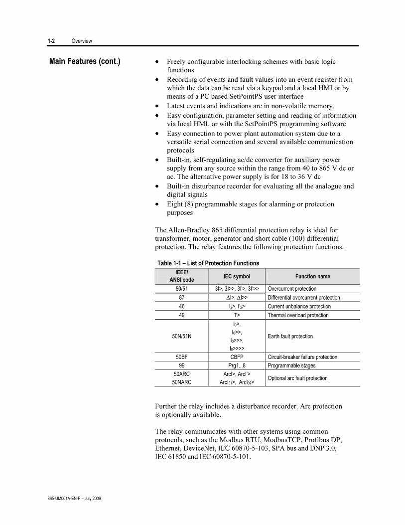
The Allen-Bradley 865 differential protection relay is ideal for
transformer, motor, generator and short cable (100) differential
protection. The relay features the following protection functions.
Table 1-1 – List of Protection Functions
IEEE/
ANSI code IEC symbol Function name
50/51 3I>, 3I>>, 3I’>, 3I’>> Overcurrent protection
87 ∆I>, ∆I>> Differential overcurrent protection
46 I2>, I’2> Current unbalance protection
49 T> Thermal overload protection
50N/51N
I0>,
I0>>,
I0>>>,
I0>>>>
Earth fault protection
50BF CBFP Circuit-breaker failure protection
99 Prg1...8 Programmable stages
50ARC
50NARC
ArcI>, ArcI’>
ArcI01>, ArcI02> Optional arc fault protection
Further the relay includes a disturbance recorder. Arc protection
is optionally available.
The relay communicates with other systems using common
protocols, such as the Modbus RTU, ModbusTCP, Profibus DP,
Ethernet, DeviceNet, IEC 60870-5-103, SPA bus and DNP 3.0,
IEC 61850 and IEC 60870-5-101.
Main Features (cont.)
Overview 1-3
865-UM001A-EN-P – July 2009
User Interface
The relay can be controlled in three ways:
• Locally with the push-buttons on the relay front panel
• Locally using a PC connected to the serial port on the front panel
or on the rear panel of the relay (both cannot be used
simultaneously)
• Via remote control over the remote control port on the relay rear
panel.
Operating Safety
A T T E N T I O NA T T E N T I O N
The terminals on the rear panel of the relay may
carry dangerous voltages, even if the auxiliary
voltage is switched off. A live current
transformer secondary circuit must not be
opened. Disconnecting a live circuit may cause
dangerous voltages! Any operational measures
must be carried out according to national and
local handling directives and instructions.
Carefully read through all operation instructions before any
operational measures are carried out.

1-4 Overview
865-UM001A-EN-P – July 2009
Chapter 2
865-UM001A-EN-P – July 2009
Local Panel User Interface Relay Front Panel The figure below shows, as an example, the front panel of the
Allen-Bradley 865 relay and the location of the user interface elements used for local control.
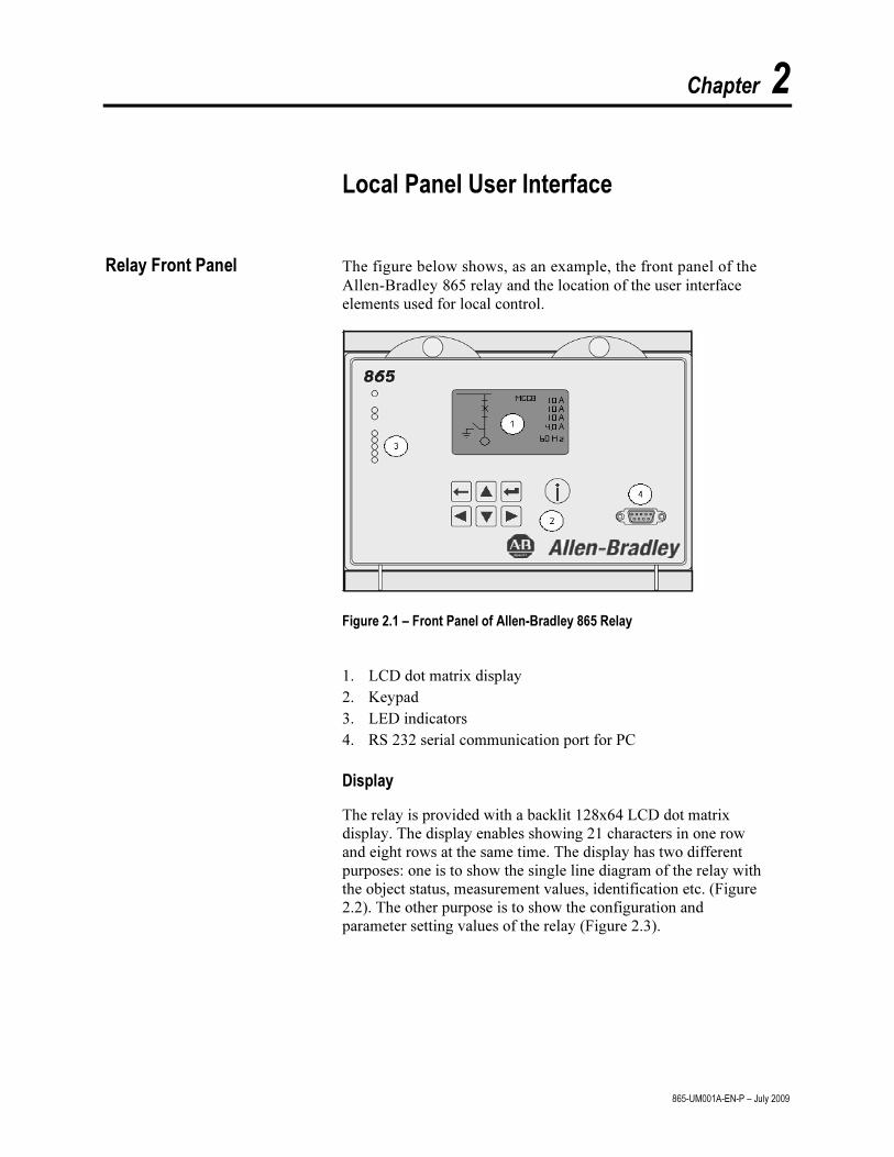
Figure 2.1 – Front Panel of Allen-Bradley 865 Relay
1. LCD dot matrix display 2. Keypad 3. LED indicators 4. RS 232 serial communication port for PC
Display
The relay is provided with a backlit 128x64 LCD dot matrix display. The display enables showing 21 characters in one row and eight rows at the same time. The display has two different purposes: one is to show the single line diagram of the relay with the object status, measurement values, identification etc. (Figure 2.2). The other purpose is to show the configuration and parameter setting values of the relay (Figure 2.3).
2-2 Local Panel User Interface
865-UM001A-EN-P – July 2009
23
4
5
1
6
K0006 L
AR: 1
50.02 Hz
Q1
Q0
Q3
Q9
Q4
7
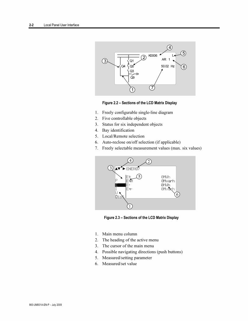
Figure 2.2 – Sections of the LCD Matrix Display
1. Freely configurable single-line diagram 2. Five controllable objects 3. Status for six independent objects 4. Bay identification 5. Local/Remote selection 6. Auto-reclose on/off selection (if applicable) 7. Freely selectable measurement values (max. six values)
Figure 2.3 – Sections of the LCD Matrix Display
1. Main menu column 2. The heading of the active menu 3. The cursor of the main menu 4. Possible navigating directions (push buttons) 5. Measured/setting parameter 6. Measured/set value

Local Panel User Interface 2-3
865-UM001A-EN-P – July 2009
Backlight Control
Display backlight can be switched on with a digital input, virtual
input or virtual output. LOCALPANEL CONF/Display backlight
ctrl setting is used for selecting trigger input for backlight control. When the selected input activates (rising edge), display backlight is set on for 60 minutes.
Menu Navigation and Pointers
1. Use the arrow keys UP and DOWN to move up and down in the main menu, that is, on the left-hand side of the display. The active main menu option is indicated with a cursor. The options in the main menu items are abbreviations, e.g. Evnt = events.
2. After any selection, the arrow symbols in the upper left corner of the display show the possible navigating directions (applicable navigation keys) in the menu.
3. The name of the active submenu and a possible ANSI code of the selected function are shown in the upper part of the display, e.g. CURRENTS.
4. Further, each display holds the measured values and units of one or more quantities or parameters, e.g. ILmax 300A.
Keypad
You can navigate in the menu and set the required parameter values using the keypad and the guidance given in the display. Furthermore, the keypad is used to control objects and switches on the single line diagram display. The keypad is composed of four arrow keys, one cancel key, one enter key and one info key.
Figure 2-4 – Keys on the Keypad
1. Enter and confirmation key (ENTER) 2. Cancel key (CANCEL) 3. Up/Down [Increase/Decrease] arrow keys (UP/DOWN)
2-4 Local Panel User Interface
865-UM001A-EN-P – July 2009
4. Keys for selecting submenus [selecting a digit in a numerical value] (LEFT/RIGHT)
5. Additional information key (INFO)
NOTE: The term, which is used for the buttons in this manual, is inside the rounded brackets.
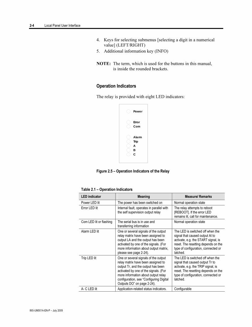
Operation Indicators The relay is provided with eight LED indicators:
Power
Error
Com
Alarm
Trip
A
B
C
Figure 2.5 – Operation Indicators of the Relay
Table 2.1 – Operation Indicators
LED indicator Meaning Measure/ Remarks
Power LED lit The power has been switched on Normal operation state
Error LED lit Internal fault, operates in parallel with the self supervision output relay
The relay attempts to reboot [REBOOT]. If the error LED remains lit, call for maintenance.
Com LED lit or flashing The serial bus is in use and transferring information
Normal operation state
Alarm LED lit One or several signals of the output relay matrix have been assigned to output LA and the output has been activated by one of the signals. (For more information about output matrix, please see page 2-24).
The LED is switched off when the signal that caused output Al to activate, e.g. the START signal, is reset. The resetting depends on the type of configuration, connected or latched.
Trip LED lit One or several signals of the output relay matrix have been assigned to output Tr, and the output has been activated by one of the signals. (For more information about output relay configuration, see “Configuring Digital Outputs DO” on page 2-24).
The LED is switched off when the signal that caused output Tr to activate, e.g. the TRIP signal, is reset. The resetting depends on the type of configuration, connected or latched.
A- C LED lit Application-related status indicators. Configurable
Local Panel User Interface 2-5
865-UM001A-EN-P – July 2009
Resetting Latched Indicators and Output Relays
All the indicators and output relays can be given a latching function in the configuration.
There are several ways to reset latched indicators and relays:
• From the alarm list, move back to the initial display by pushing the CANCEL key for approx. 3 s. Then reset the latched indicators and output relays by pushing the ENTER key.
• Acknowledge each event in the alarm list one by one by pushing the ENTER key equivalent times. Then, in the initial display, reset the latched indicators and output relays by pushing the ENTER key.
The latched indicators and relays can also be reset via a remote
communication bus or via a digital input configured for that purpose.
Adjusting Display Contrast
The readability of the LCD varies with the brightness and the temperature of the environment. The contrast of the display can be adjusted via the PC user interface, and SetPointPS software.
Local Panel Operations The front panel can be used to control objects, change the local/ remote status, read the measured values, set parameters, and to configure relay functions. Some parameters, however, can only be set by means of a PC connected to one of the local communication ports. Some parameters are factory-set.
Navigating in Menus All the menu functions are based on the main menu/submenu structure:
1. Use the arrow keys UP and DOWN to move up and down in the main menu.
2. To move to a submenu, repeatedly push the RIGHT key until the required submenu is shown. Correspondingly, push the LEFT key to return to the main menu.
3. Push the ENTER key to confirm the selected submenu. If there are more than six items in the selected submenu, a black line appears to the right side of the display (Figure 2.6). It is then possible to scroll down in the submenu.
4. Push the CANCEL key to cancel a selection.
2-6 Local Panel User Interface
865-UM001A-EN-P – July 2009
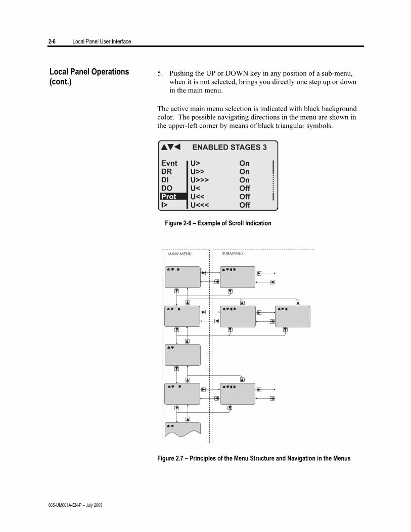
5. Pushing the UP or DOWN key in any position of a sub-menu,
when it is not selected, brings you directly one step up or down in the main menu.
The active main menu selection is indicated with black background
color. The possible navigating directions in the menu are shown in the upper-left corner by means of black triangular symbols.
Figure 2-6 – Example of Scroll Indication
Figure 2.7 – Principles of the Menu Structure and Navigation in the Menus
Local Panel Operations (cont.)
Local Panel User Interface 2-7
865-UM001A-EN-P – July 2009
6. Push the INFO key to obtain additional information about any menu item.
7. Push the CANCEL key to revert to the normal display.
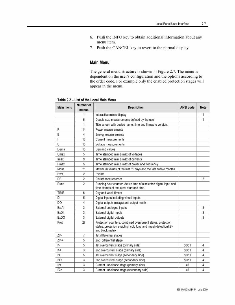
Main Menu
The general menu structure is shown in Figure 2.7. The menu is dependent on the user's configuration and the options according to the order code. For example only the enabled protection stages will appear in the menu.
Table 2.2 – List of the Local Main Menu
Main menu Number of
menus Description ANSI code Note
1 Interactive mimic display 1
5 Double size measurements defined by the user 1
1 Title screen with device name, time and firmware version.
P 14 Power measurements
E 4 Energy measurements
I 13 Current measurements
U 15 Voltage measurements
Dema 15 Demand values
Umax 5 Time stamped min & max of voltages
Imax 9 Time stamped min & max of currents
Pmax 5 Time stamped min & max of power and frequency
Mont 21 Maximum values of the last 31 days and the last twelve months
Evnt 2 Events
DR 2 Disturbance recorder 2
Runh 2 Running hour counter. Active time of a selected digital input and time stamps of the latest start and stop.
TIMR 6 Day and week timers
DI 5 Digital inputs including virtual inputs
DO 4 Digital outputs (relays) and output matrix
ExtAI 3 External analogue inputs 3
ExDI 3 External digital inputs 3
ExDO 3 External digital outputs 3
Prot 27 Protection counters, combined overcurrent status, protection status, protection enabling, cold load and inrush detectionIf2> and block matrix
ΔI> 7 1st differential stages
ΔI>> 5 2nd differential stage
I> 5 1st overcurrent stage (primary side) 50/51 4
I>> 3 2nd overcurrent stage (primary side) 50/51 4
I’> 5 1st overcurrent stage (secondary side) 50/51 4
I’>> 3 2nd overcurrent stage (secondary side) 50/51 4
I2> 3 Current unbalance stage (primary side) 46 4
I’2> 3 Current unbalance stage (secondary side) 46 4
2-8 Local Panel User Interface
865-UM001A-EN-P – July 2009
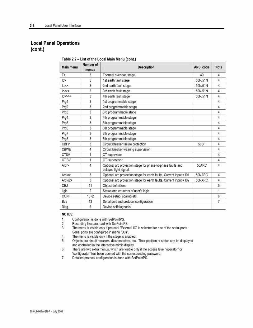
Table 2.2 – List of the Local Main Menu (cont.)
Main menu Number of
menus Description ANSI code Note
T> 3 Thermal overload stage 49 4
Io> 5 1st earth fault stage 50N/51N 4
Io>> 3 2nd earth fault stage 50N/51N 4
Io>>> 3 3rd earth fault stage 50N/51N 4
Io>>>> 3 4th earth fault stage 50N/51N 4
Prg1 3 1st programmable stage 4
Prg2 3 2nd programmable stage 4
Prg3 3 3rd programmable stage 4
Prg4 3 4th programmable stage 4
Prg5 3 5th programmable stage 4
Prg6 3 6th programmable stage 4
Prg7 3 7th programmable stage 4
Prg8 3 8th programmable stage 4
CBFP 3 Circuit breaker failure protection 50BF 4
CBWE 4 Circuit breaker wearing supervision 4
CTSV 1 CT supervisor 4
CT’SV 1 CT’ supervisor 4
ArcI> 4 Optional arc protection stage for phase-to-phase faults and delayed light signal.
50ARC 4
ArcIo> 3 Optional arc protection stage for earth faults. Current input = I01 50NARC 4
ArcIo2> 3 Optional arc protection stage for earth faults. Current input = I02 50NARC 4
OBJ 11 Object definitions 5
Lgic 2 Status and counters of user's logic 1
CONF 10+2 Device setup, scaling etc. 6
Bus 13 Serial port and protocol configuration 7
Diag 6 Device selfdiagnosis
NOTES:
1. Configuration is done with SetPointPS. 2. Recording files are read with SetPointPS. 3. The menu is visible only if protocol ”External IO” is selected for one of the serial ports. Serial ports are configured in menu ”Bus”. 4. The menu is visible only if the stage is enabled. 5. Objects are circuit breakers, disconnectors, etc. Their position or status can be displayed and controlled in the interactive mimic display. 6. There are two extra menus, which are visible only if the access level ”operator” or ”configurator” has been opened with the corresponding password. 7. Detailed protocol configuration is done with SetPointPS.
Local Panel Operations (cont.)
Local Panel User Interface 2-9
865-UM001A-EN-P – July 2009
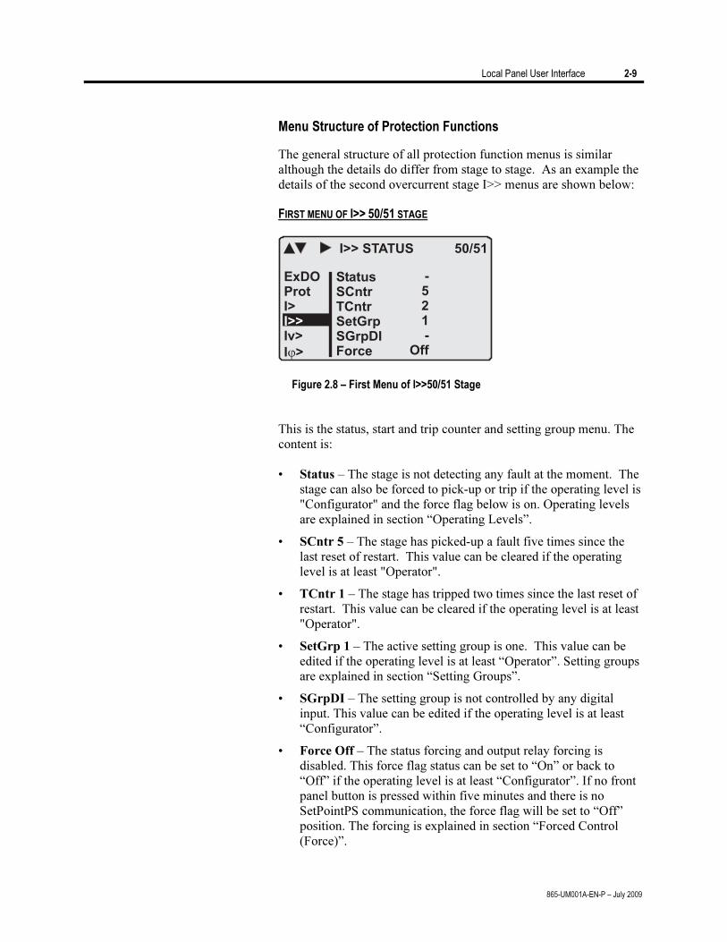
Menu Structure of Protection Functions
The general structure of all protection function menus is similar although the details do differ from stage to stage. As an example the details of the second overcurrent stage I>> menus are shown below:
FIRST MENU OF I>> 50/51 STAGE
I>> STATUS 50/51
StatusSCntrTCntrSetGrpSGrpDIForce
-521-
Off
ExDOProtI>
Iv>
I >
I>>
Figure 2.8 – First Menu of I>>50/51 Stage
This is the status, start and trip counter and setting group menu. The
content is: • Status – The stage is not detecting any fault at the moment. The
stage can also be forced to pick-up or trip if the operating level is "Configurator" and the force flag below is on. Operating levels are explained in section “Operating Levels”.
• SCntr 5 – The stage has picked-up a fault five times since the last reset of restart. This value can be cleared if the operating level is at least "Operator".
• TCntr 1 – The stage has tripped two times since the last reset of restart. This value can be cleared if the operating level is at least "Operator".
• SetGrp 1 – The active setting group is one. This value can be edited if the operating level is at least “Operator”. Setting groups are explained in section “Setting Groups”.
• SGrpDI – The setting group is not controlled by any digital input. This value can be edited if the operating level is at least “Configurator”.
• Force Off – The status forcing and output relay forcing is disabled. This force flag status can be set to “On” or back to “Off” if the operating level is at least “Configurator”. If no front panel button is pressed within five minutes and there is no SetPointPS communication, the force flag will be set to “Off” position. The forcing is explained in section “Forced Control (Force)”.
2-10 Local Panel User Interface
865-UM001A-EN-P – July 2009
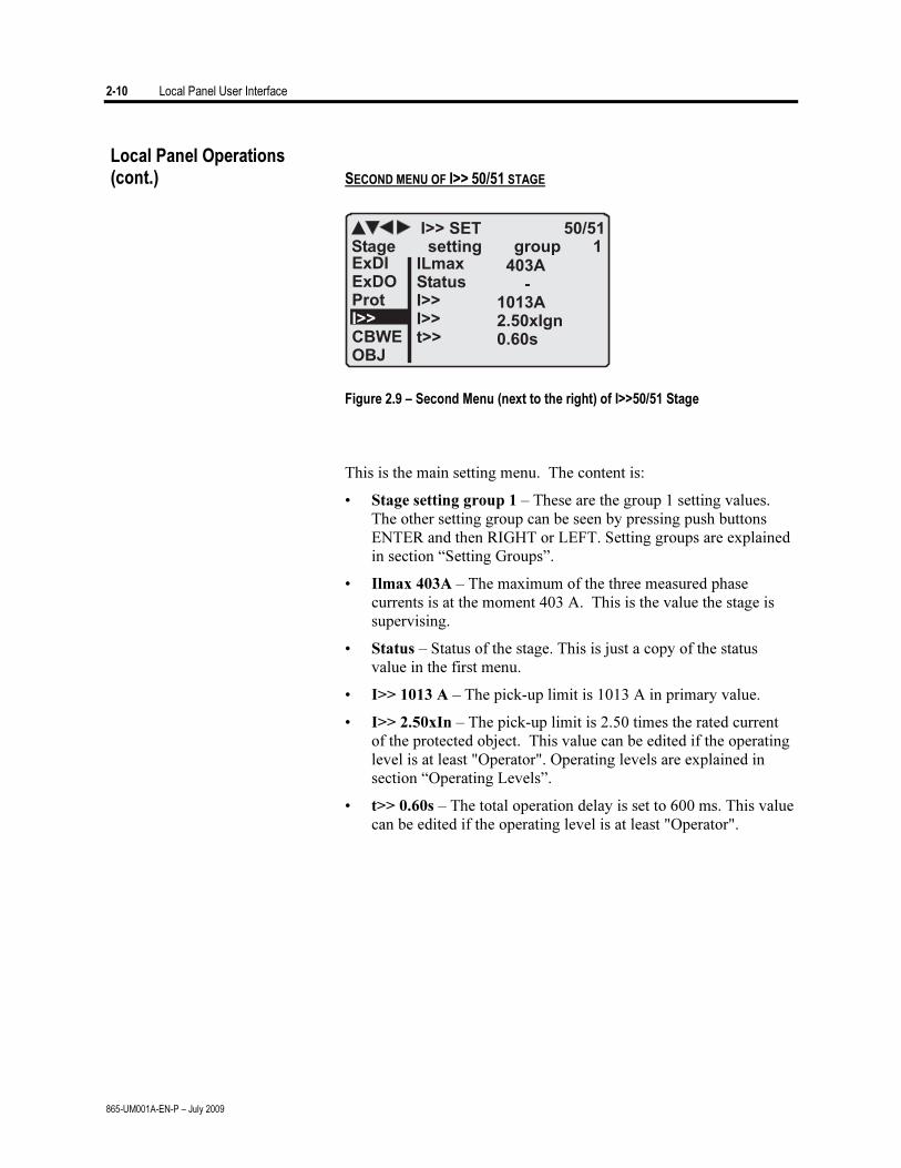
SECOND MENU OF I>> 50/51 STAGE
I>> SET 50/51
ILmaxStatusI>>I>>t>>
403A-
1013A2.50xIgn0.60s
ExDIExDOProt
CBWEOBJ
I>>
Stage setting group 1
Figure 2.9 – Second Menu (next to the right) of I>>50/51 Stage
This is the main setting menu. The content is:
• Stage setting group 1 – These are the group 1 setting values. The other setting group can be seen by pressing push buttons ENTER and then RIGHT or LEFT. Setting groups are explained in section “Setting Groups”.
• Ilmax 403A – The maximum of the three measured phase currents is at the moment 403 A. This is the value the stage is supervising.
• Status – Status of the stage. This is just a copy of the status value in the first menu.
• I>> 1013 A – The pick-up limit is 1013 A in primary value.
• I>> 2.50xIn – The pick-up limit is 2.50 times the rated current of the protected object. This value can be edited if the operating level is at least "Operator". Operating levels are explained in section “Operating Levels”.
• t>> 0.60s – The total operation delay is set to 600 ms. This value can be edited if the operating level is at least "Operator".
Local Panel Operations (cont.)
Local Panel User Interface 2-11
865-UM001A-EN-P – July 2009
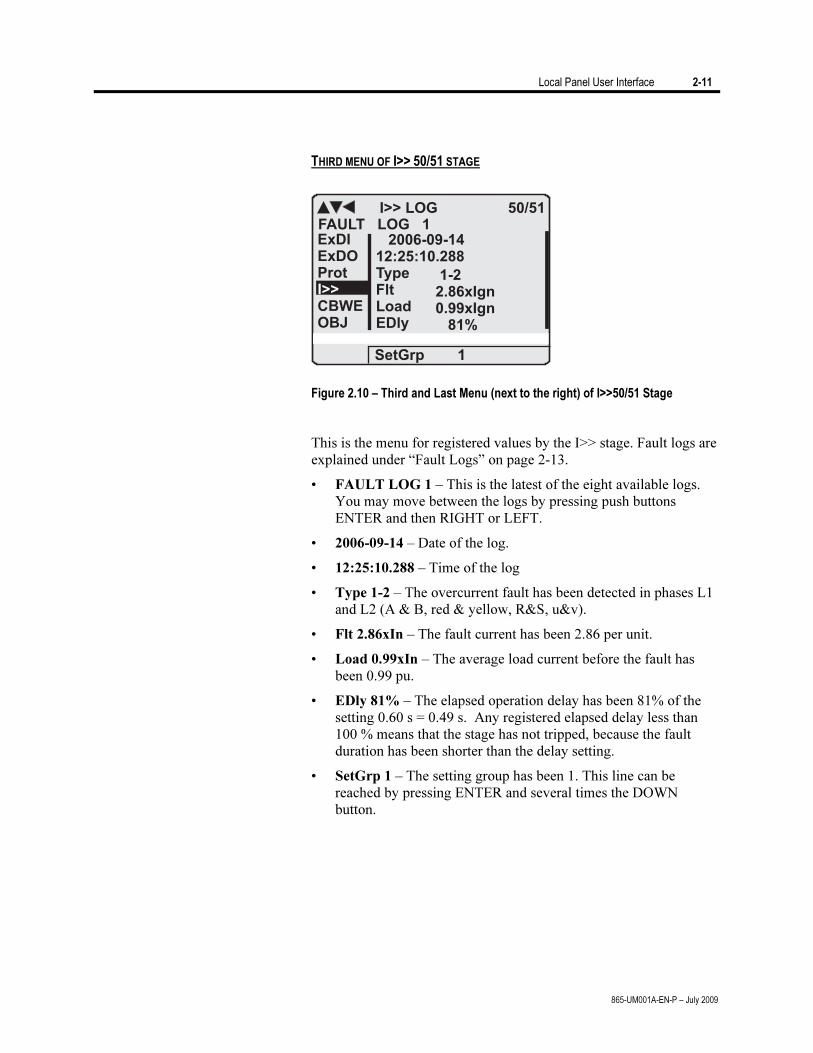
THIRD MENU OF I>> 50/51 STAGE
I>> LOG 50/51
2006-09-1412:25:10.288TypeFltLoadEDly
1-22.86xIgn0.99xIgn
81%
ExDIExDOProt
CBWEOBJ
I>>
FAULT LOG 1
SetGrp 1
Figure 2.10 – Third and Last Menu (next to the right) of I>>50/51 Stage
This is the menu for registered values by the I>> stage. Fault logs are
explained under “Fault Logs” on page 2-13.
• FAULT LOG 1 – This is the latest of the eight available logs. You may move between the logs by pressing push buttons ENTER and then RIGHT or LEFT.
• 2006-09-14 – Date of the log.
• 12:25:10.288 – Time of the log
• Type 1-2 – The overcurrent fault has been detected in phases L1 and L2 (A & B, red & yellow, R&S, u&v).
• Flt 2.86xIn – The fault current has been 2.86 per unit.
• Load 0.99xIn – The average load current before the fault has been 0.99 pu.
• EDly 81% – The elapsed operation delay has been 81% of the setting 0.60 s = 0.49 s. Any registered elapsed delay less than 100 % means that the stage has not tripped, because the fault duration has been shorter than the delay setting.
• SetGrp 1 – The setting group has been 1. This line can be reached by pressing ENTER and several times the DOWN button.
2-12 Local Panel User Interface
865-UM001A-EN-P – July 2009
Setting Groups
Most of the protection functions of the relay have two setting groups. These groups are useful for example when the network topology is changed frequently. The active group can be changed by a digital input, through remote communication or locally by using the local panel.
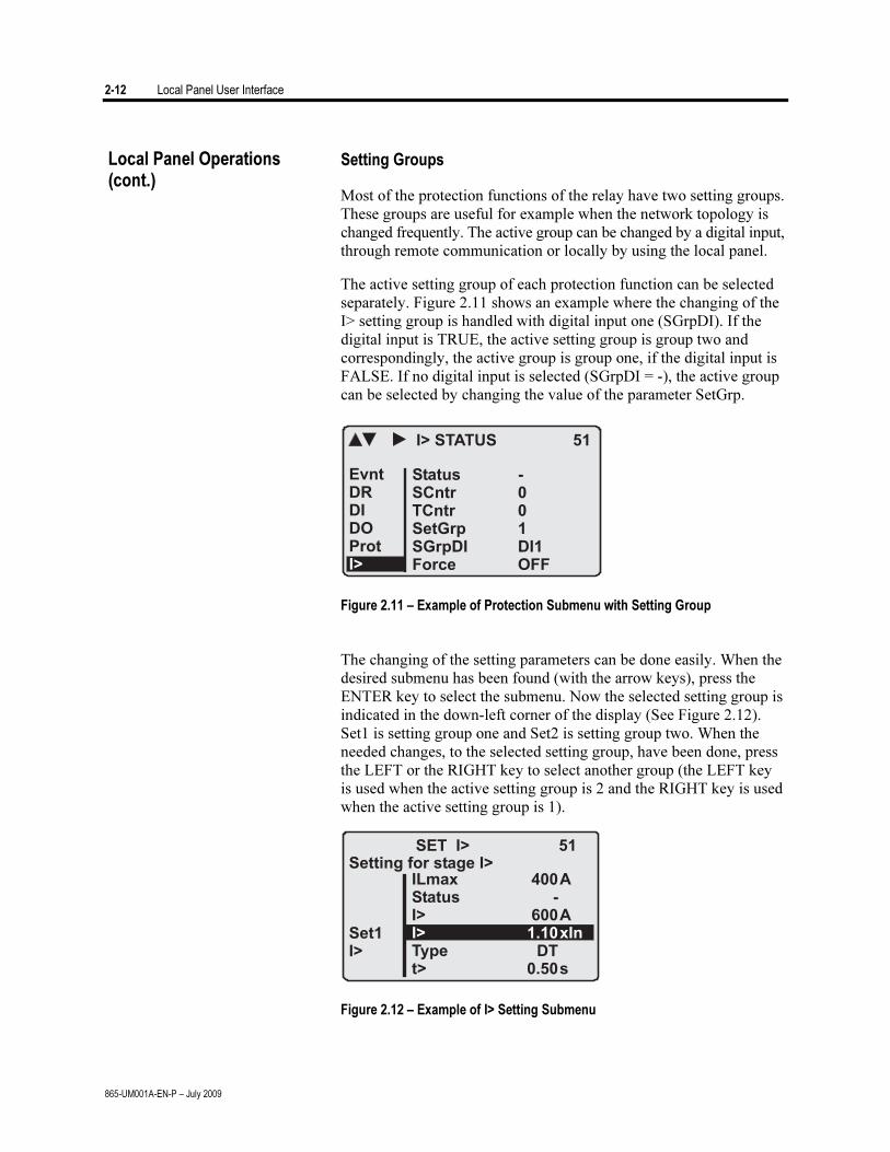
The active setting group of each protection function can be selected separately. Figure 2.11 shows an example where the changing of the I> setting group is handled with digital input one (SGrpDI). If the digital input is TRUE, the active setting group is group two and correspondingly, the active group is group one, if the digital input is FALSE. If no digital input is selected (SGrpDI = -), the active group can be selected by changing the value of the parameter SetGrp.
Figure 2.11 – Example of Protection Submenu with Setting Group
The changing of the setting parameters can be done easily. When the
desired submenu has been found (with the arrow keys), press the ENTER key to select the submenu. Now the selected setting group is indicated in the down-left corner of the display (See Figure 2.12). Set1 is setting group one and Set2 is setting group two. When the needed changes, to the selected setting group, have been done, press the LEFT or the RIGHT key to select another group (the LEFT key is used when the active setting group is 2 and the RIGHT key is used when the active setting group is 1).
Figure 2.12 – Example of I> Setting Submenu
Local Panel Operations (cont.)
Local Panel User Interface 2-13
865-UM001A-EN-P – July 2009
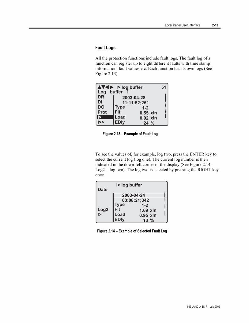
Fault Logs All the protection functions include fault logs. The fault log of a
function can register up to eight different faults with time stamp information, fault values etc. Each function has its own logs (See Figure 2.13).
Figure 2.13 – Example of Fault Log
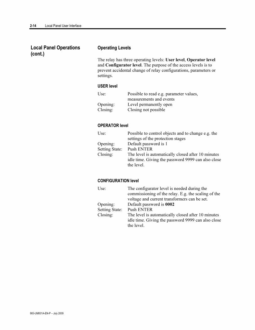
To see the values of, for example, log two, press the ENTER key to
select the current log (log one). The current log number is then indicated in the down-left corner of the display (See Figure 2.14, Log2 = log two). The log two is selected by pressing the RIGHT key once.
Figure 2.14 – Example of Selected Fault Log
2-14 Local Panel User Interface
865-UM001A-EN-P – July 2009
Operating Levels
The relay has three operating levels: User level, Operator level
and Configurator level. The purpose of the access levels is to prevent accidental change of relay configurations, parameters or settings.
USER level
Use: Possible to read e.g. parameter values, measurements and events
Opening: Level permanently open Closing: Closing not possible OPERATOR level
Use: Possible to control objects and to change e.g. the settings of the protection stages
Opening: Default password is 1 Setting State: Push ENTER Closing: The level is automatically closed after 10 minutes
idle time. Giving the password 9999 can also close the level.
CONFIGURATION level
Use: The configurator level is needed during the commissioning of the relay. E.g. the scaling of the voltage and current transformers can be set.
Opening: Default password is 0002 Setting State: Push ENTER Closing: The level is automatically closed after 10 minutes
idle time. Giving the password 9999 can also close the level.
Local Panel Operations (cont.)
Local Panel User Interface 2-15
865-UM001A-EN-P – July 2009
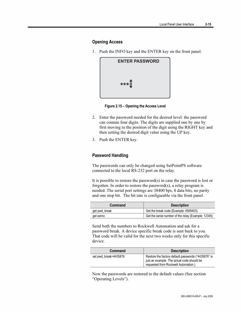
Opening Access
1. Push the INFO key and the ENTER key on the front panel.
ENTER PASSWORD
0***
Figure 2.15 – Opening the Access Level
2. Enter the password needed for the desired level: the password can contain four digits. The digits are supplied one by one by first moving to the position of the digit using the RIGHT key and then setting the desired digit value using the UP key.
3. Push the ENTER key.
Password Handling The passwords can only be changed using SetPointPS software
connected to the local RS-232 port on the relay. It is possible to restore the password(s) in case the password is lost or
forgotten. In order to restore the password(s), a relay program is needed. The serial port settings are 38400 bps, 8 data bits, no parity and one stop bit. The bit rate is configurable via the front panel.
Command Description
get pwd_break Get the break code (Example: 6569403)
get serno Get the serial number of the relay (Example: 12345)
Send both the numbers to Rockwell Automation and ask for a
password break. A device specific break code is sent back to you. That code will be valid for the next two weeks only for this specific device.
Command Description
set pwd_break=4435876 Restore the factory default passwords (“4435876” is just an example. The actual code should be requested from Rockwell Automation.)
Now the passwords are restored to the default values (See section “Operating Levels”).
2-16 Local Panel User Interface
865-UM001A-EN-P – July 2009
Operating Measures Control Functions The default display of the local panel is a single-line diagram
including relay identification, Local/Remote indication, Auto-reclose on/off selection and selected analogue measurement values.
Please note that the operator password must be active in order to be
able to control the objects. Please refer to ‘Opening Access’ on page 2-15.
Toggling Local/Remote Control
1. Push the ENTER key. The previously activated object starts to blink.
2. Select the Local/Remote object (“L” or “R” squared) by using the arrow keys.
3. Push the ENTER key. The L/R dialog opens. Select “REMOTE” to enable remote control and disable local control. Select “LOCAL” to enable local control and disable remote control.
4. Confirm the setting by pushing the ENTER key. The Local/Remote state will change.
Object Control
1. Push the ENTER key. The previously activated object starts to blink.
2. Select the object to control by using the arrow keys. Please note that only controllable objects can be selected.
3. Push the ENTER key. A control dialog opens.
4. Select the “Open” or “Close” command by using the UP and DOWN arrow keys.
5. Confirm the operation by pushing the ENTER key. The state of the object changes.
Toggling Virtual Inputs
1. Push the ENTER key. The previously activated object starts to blink.
2. Select the virtual input object (empty or black square)
3. The dialog opens
4. Select “VIon” to activate the virtual input or select “VIoff” to deactivate the virtual input
Local Panel User Interface 2-17
865-UM001A-EN-P – July 2009
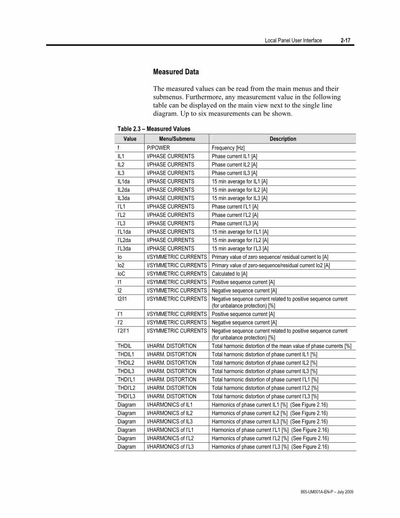
Measured Data The measured values can be read from the main menus and their
submenus. Furthermore, any measurement value in the following table can be displayed on the main view next to the single line diagram. Up to six measurements can be shown.
Table 2.3 – Measured Values
Value Menu/Submenu Description
f P/POWER Frequency [Hz]
IL1 I/PHASE CURRENTS Phase current IL1 [A]
IL2 I/PHASE CURRENTS Phase current IL2 [A]
IL3 I/PHASE CURRENTS Phase current IL3 [A]
IL1da I/PHASE CURRENTS 15 min average for IL1 [A]
IL2da I/PHASE CURRENTS 15 min average for IL2 [A]
IL3da I/PHASE CURRENTS 15 min average for IL3 [A]
I’L1 I/PHASE CURRENTS Phase current I’L1 [A]
I’L2 I/PHASE CURRENTS Phase current I’L2 [A]
I’L3 I/PHASE CURRENTS Phase current I’L3 [A]
I’L1da I/PHASE CURRENTS 15 min average for I’L1 [A]
I’L2da I/PHASE CURRENTS 15 min average for I’L2 [A]
I’L3da I/PHASE CURRENTS 15 min average for I’L3 [A]
Io I/SYMMETRIC CURRENTS Primary value of zero sequence/ residual current Io [A]
Io2 I/SYMMETRIC CURRENTS Primary value of zero-sequence/residual current Io2 [A]
IoC I/SYMMETRIC CURRENTS Calculated Io [A]
I1 I/SYMMETRIC CURRENTS Positive sequence current [A]
I2 I/SYMMETRIC CURRENTS Negative sequence current [A]
I2/I1 I/SYMMETRIC CURRENTS Negative sequence current related to positive sequence current (for unbalance protection) [%]
I’1 I/SYMMETRIC CURRENTS Positive sequence current [A]
I’2 I/SYMMETRIC CURRENTS Negative sequence current [A]
I’2/I’1 I/SYMMETRIC CURRENTS Negative sequence current related to positive sequence current (for unbalance protection) [%]
THDIL I/HARM. DISTORTION Total harmonic distortion of the mean value of phase currents [%]
THDIL1 I/HARM. DISTORTION Total harmonic distortion of phase current IL1 [%]
THDIL2 I/HARM. DISTORTION Total harmonic distortion of phase current IL2 [%]
THDIL3 I/HARM. DISTORTION Total harmonic distortion of phase current IL3 [%]
THDI’L1 I/HARM. DISTORTION Total harmonic distortion of phase current I’L1 [%]
THDI’L2 I/HARM. DISTORTION Total harmonic distortion of phase current I’L2 [%]
THDI’L3 I/HARM. DISTORTION Total harmonic distortion of phase current I’L3 [%]
Diagram I/HARMONICS of IL1 Harmonics of phase current IL1 [%] (See Figure 2.16)
Diagram I/HARMONICS of IL2 Harmonics of phase current IL2 [%] (See Figure 2.16)
Diagram I/HARMONICS of IL3 Harmonics of phase current IL3 [%] (See Figure 2.16)
Diagram I/HARMONICS of I’L1 Harmonics of phase current I’L1 [%] (See Figure 2.16)
Diagram I/HARMONICS of I’L2 Harmonics of phase current I’L2 [%] (See Figure 2.16)
Diagram I/HARMONICS of I’L3 Harmonics of phase current I’L3 [%] (See Figure 2.16)
2-18 Local Panel User Interface
865-UM001A-EN-P – July 2009
Operating measures (cont.)
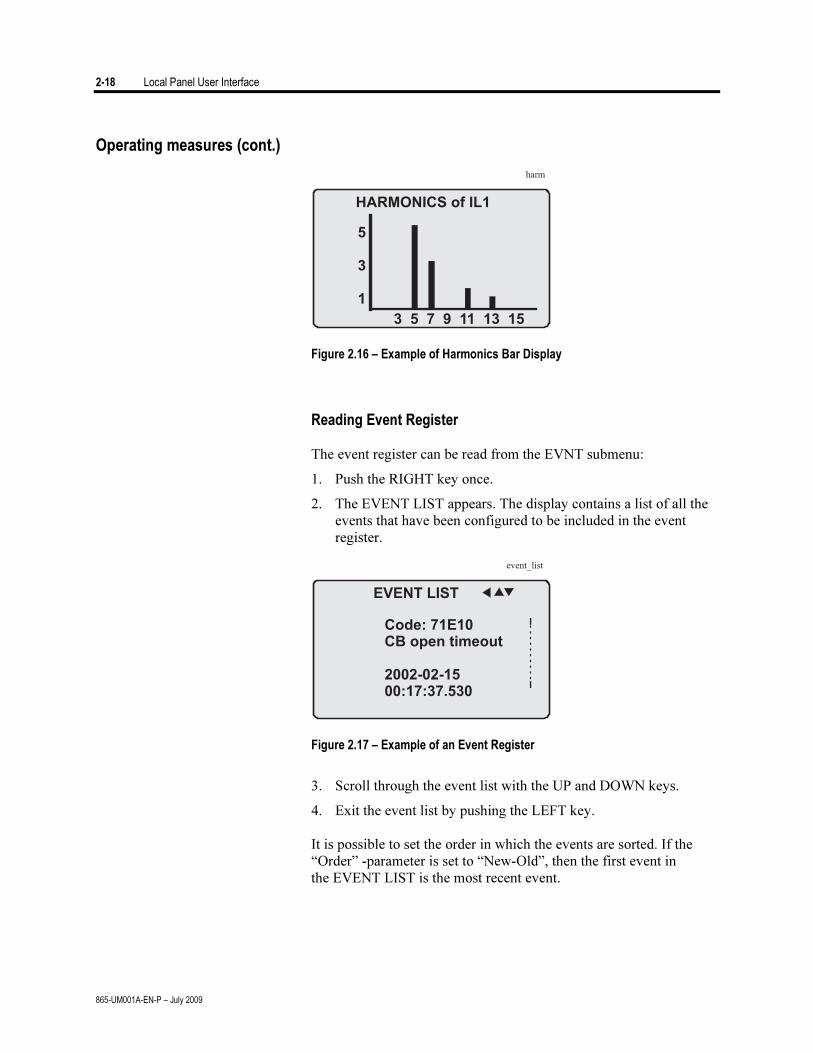
Figure 2.16 – Example of Harmonics Bar Display
Reading Event Register The event register can be read from the EVNT submenu:
1. Push the RIGHT key once.
2. The EVENT LIST appears. The display contains a list of all the events that have been configured to be included in the event register.
Figure 2.17 – Example of an Event Register
3. Scroll through the event list with the UP and DOWN keys.
4. Exit the event list by pushing the LEFT key. It is possible to set the order in which the events are sorted. If the
“Order” -parameter is set to “New-Old”, then the first event in the EVENT LIST is the most recent event.
Local Panel User Interface 2-19
865-UM001A-EN-P – July 2009
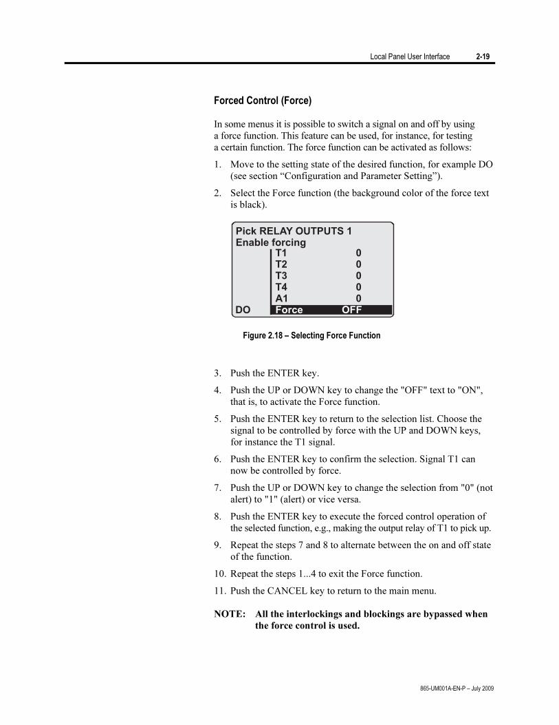
Forced Control (Force) In some menus it is possible to switch a signal on and off by using
a force function. This feature can be used, for instance, for testing a certain function. The force function can be activated as follows:
1. Move to the setting state of the desired function, for example DO (see section “Configuration and Parameter Setting”).
2. Select the Force function (the background color of the force text is black).
Figure 2.18 – Selecting Force Function
3. Push the ENTER key.
4. Push the UP or DOWN key to change the "OFF" text to "ON", that is, to activate the Force function.
5. Push the ENTER key to return to the selection list. Choose the signal to be controlled by force with the UP and DOWN keys, for instance the T1 signal.
6. Push the ENTER key to confirm the selection. Signal T1 can now be controlled by force.
7. Push the UP or DOWN key to change the selection from "0" (not alert) to "1" (alert) or vice versa.
8. Push the ENTER key to execute the forced control operation of the selected function, e.g., making the output relay of T1 to pick up.
9. Repeat the steps 7 and 8 to alternate between the on and off state of the function.
10. Repeat the steps 1...4 to exit the Force function.
11. Push the CANCEL key to return to the main menu.
NOTE: All the interlockings and blockings are bypassed when
the force control is used.
2-20 Local Panel User Interface
865-UM001A-EN-P – July 2009
The minimum procedure to configure a relay is:
1. Open the access level "Configurator". The default password for configurator access level is 2.
2. Set the rated values in menu [CONF] including at least current transformers and a protected transformer rating. Also the date and time settings are in this same main menu.
3. Enable the needed protection functions and disable the rest of the protection functions in main menu [Prot].
4. Set the setting parameter of the enable protection stages according the application.
5. Connect the output relays to the start and trip signals of the enabled protection stages using the output matrix. This can be done in main menu [DO], although the SetPointPS program is recommended for output matrix editing.
6. Configure the needed digital inputs in main menu [DI].
7. Configure blocking and interlockings for protection stages using the block matrix. This can be done in main menu [Prot], although SetPointPS is recommended for block matrix editing.
Some of the parameters can only be changed via the RS-232
serial port using the SetPointPS software. Such parameters, (for example passwords, blockings and mimic configuration) are normally set only during commissioning.
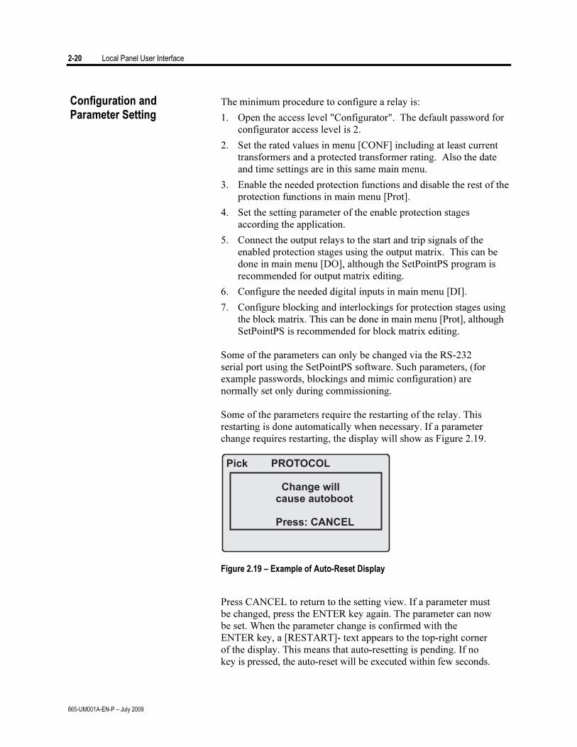
Some of the parameters require the restarting of the relay. This
restarting is done automatically when necessary. If a parameter change requires restarting, the display will show as Figure 2.19.
Figure 2.19 – Example of Auto-Reset Display
Press CANCEL to return to the setting view. If a parameter must
be changed, press the ENTER key again. The parameter can now be set. When the parameter change is confirmed with the ENTER key, a [RESTART]- text appears to the top-right corner of the display. This means that auto-resetting is pending. If no key is pressed, the auto-reset will be executed within few seconds.
Configuration and Parameter Setting
Local Panel User Interface 2-21
865-UM001A-EN-P – July 2009
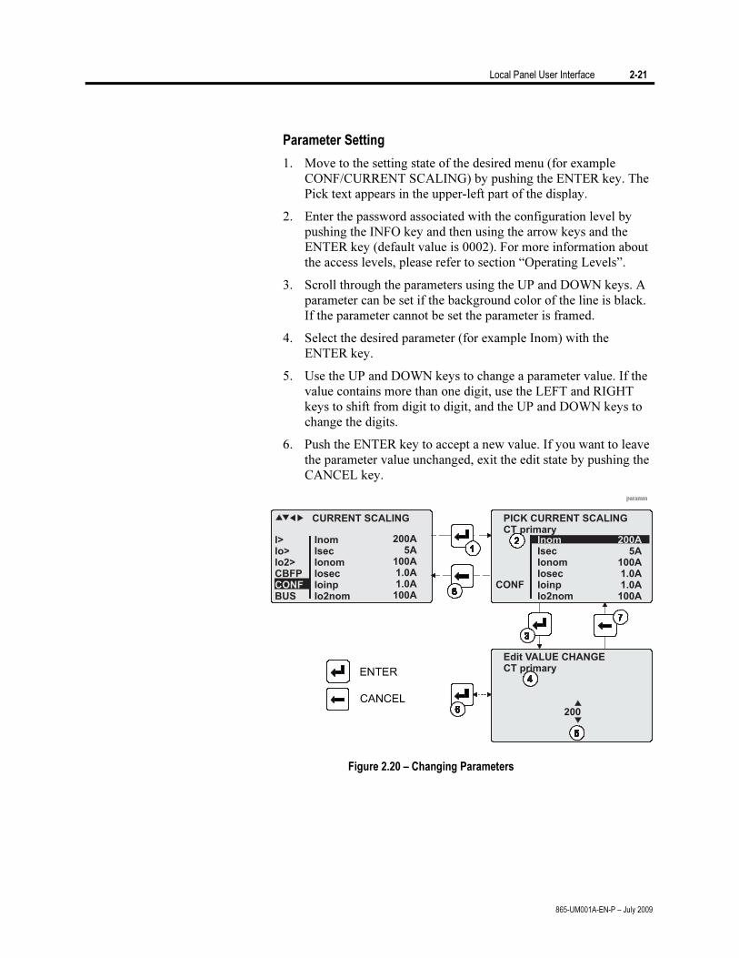
Parameter Setting
1. Move to the setting state of the desired menu (for example CONF/CURRENT SCALING) by pushing the ENTER key. The Pick text appears in the upper-left part of the display.
2. Enter the password associated with the configuration level by pushing the INFO key and then using the arrow keys and the ENTER key (default value is 0002). For more information about the access levels, please refer to section “Operating Levels”.
3. Scroll through the parameters using the UP and DOWN keys. A parameter can be set if the background color of the line is black. If the parameter cannot be set the parameter is framed.
4. Select the desired parameter (for example Inom) with the ENTER key.
5. Use the UP and DOWN keys to change a parameter value. If the value contains more than one digit, use the LEFT and RIGHT keys to shift from digit to digit, and the UP and DOWN keys to change the digits.
6. Push the ENTER key to accept a new value. If you want to leave the parameter value unchanged, exit the edit state by pushing the CANCEL key.
Figure 2.20 – Changing Parameters
2-22 Local Panel User Interface
865-UM001A-EN-P – July 2009
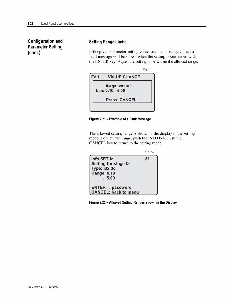
Setting Range Limits If the given parameter setting values are out-of-range values, a
fault message will be shown when the setting is confirmed with the ENTER key. Adjust the setting to be within the allowed range.
Figure 2.21 – Example of a Fault Message
The allowed setting range is shown in the display in the setting
mode. To view the range, push the INFO key. Push the CANCEL key to return to the setting mode.
Figure 2.22 – Allowed Setting Ranges shown in the Display
Configuration and Parameter Setting (cont.)

Local Panel User Interface 2-23
865-UM001A-EN-P – July 2009
Disturbance Recorder Menu DR Via the submenus of the disturbance recorder menu the
following functions and features can be read and set: DISTURBANCE RECORDER
• Recording mode (Mode) • Sample rate (Rate) • Recording time (Time) • Pre trig time (PreTrig) • Manual trigger (MnlTrig) • Count of ready records (ReadyRe)
REC. COUPLING
• Add a link to the recorder (AddLink) • Clear all links (ClrLnks)
Available links:
• DO, DI • IL, I’L • I2/In, I2/I1, I2, I1, IoCalc, I2/In, I’2/I’1, I’2, I’1, I’oCalc • f • Io2, Io1 • IL3, IL2, IL1, I’L3, I’L2, I’L1 • IL1RMS, IL2RMS, IL3RMS • ILmin, ILmax, I’Lmin, I’Lmax • ΔIl1, ΔIl2, ΔIl3 • IL1w, IL2w, IL3w, I’L1w, I’L2w, I’L3w
Configuring Digital Inputs DI The following functions can be read and set via the submenus of
the digital inputs menu: • The status of digital inputs (DIGITAL INPUTS 1-6) • Operation counters (DI COUNTERS) • Operation delay (DELAYs for DigIn) • The polarity of the input signal (INPUT POLARITY). Either
normally open (NO) or normally closed (NC) circuit. • Event enabling EVENT MASK1
2-24 Local Panel User Interface
865-UM001A-EN-P – July 2009
Configuring Digital Outputs DO The following functions can be read and set via the submenus of
the digital outputs menu: • The status of the output relays (RELAY OUTPUTS1 and 2) • The forcing of the output relays (RELAY OUTPUTS1 and 2)
(only if Force = ON): – Forced control (0 or 1) of the Trip relays – Forced control (0 or 1) of the Alarm relays – Forced control (0 or 1) of the IF relay
• The configuration of the output signals to the output relays. The configuration of the operation indicators (LED) Alarm and Trip and application specific alarm leds A, B and C (that is, the output relay matrix).
NOTE: The amount of Trip and Alarm relays depends on the relay type and optional hardware.
Protection Menu Prot The following functions can be read and set via the submenus of
the Prot menu: Reset all the counters (PROTECTION SET/ClAll) Read the status of all the protection functions (PROTECT
STATUS 1-x) Enable and disable protection functions (ENABLED STAGES
1-x) Define the interlockings between signals (only with SetPointPS).
Each stage of the protection functions can be disabled or enabled
individually in the Prot menu. When a stage is enabled, it will be in operation immediately without a need to reset the relay.
The relay includes several protection functions. However, the
processor capacity limits the number of protection functions that can be active at the same time.
Configuration and Parameter Setting (cont.)
Local Panel User Interface 2-25
865-UM001A-EN-P – July 2009
Configuration Menu CONF The following functions and features can be read and set via the
submenus of the configuration menu: DEVICE SETUP
• Bit rate for the command line interface in ports X4 and the front panel. The front panel is always using this setting. If SPABUS is selected for the rear panel local port X4, the bit rate is according SPABUS settings.
• Access level [Acc]
LANGUAGE
• List of available languages in the relay
CURRENT SCALING
• Rated phase CT primary current (Inom) • Rated phase CT secondary current (Isec) • Rated input of the relay [Iinput]. 5 A or 1 A. This is specified in
the order code of the device. • Rated phase CT’ primary current (I’nom) • Rated phase CT’ secondary current (I’sec) • Rated input of the relay [I’input]. 5 A or 1 A. This is specified in
the order code of the device. • Rated value of I0 CT primary current (Ionom) • Rated value of I0 CT secondary current (Iosec) • Rated I01 input of the relay [Ioinp]. 5 A or 1 A. This is specified
in the order code of the device. • Rated value of I02 CT primary current (Io2nom) • Rated value of I02 CT secondary current (Io2sec) • Rated I02 input of the relay [Io2inp]. 5A, 1 A or 0.2 A. This is
specified in the order code of the device. The rated input values are usually equal to the rated secondary
value of the CT.
The rated CT secondary may be greater than the rated input but the continuous current must be less than four times the rated input. In compensated, high impedance earthed and isolated networks using cable transformer to measure residual current I0, it is quite usual to use a relay with 1 A or 0.2 A input although the CT is 5 A or 1A. This increases the measurement accuracy.
The rated CT secondary may also be less than the rated input but the measurement accuracy near zero current will decrease.
2-26 Local Panel User Interface
865-UM001A-EN-P – July 2009
TRANSFORMER SETTING
• Rated voltage in IL side (typically high voltage side) • Rated voltage in I’L side (typically low voltage side) • Rated power of transformer • Connection group of transformer • Zero current compensation in IL side (If transformer is earthed in
IL side, this must set as “ON”) • Zero current compensation in I’L side (If transformer is earthed
in I’L side, this must set as “ON”) • Connection group of the unit transformer, if any. IEC marking
with capital letters Y and D for HV side and small case letters y and d for LV side combined with the dial hour is used. For example Yd11 means a wye-delta transformer where the delta side phase-to-ground voltages are leading 30° the wye side phase-to-ground voltages.
DEVICE INFO
• Relay type (Type ALLEN BRADLEY 865) • Serial number (SerN) • Software version (PrgVer) • Bootcode version (BootVer)
DATE/TIME SETUP
• Day, month and year (Date) • Time of day (Time) • Date format (Style). The choices are "yyyy-mm-dd",
"dd.nn.yyyy" and "mm/dd/yyyy".
CLOCK SYNCHRONISATION
• Digital input for minute sync pulse (SyncDI). If any digital input is not used for synchronization, select "".
• Daylight saving time for NTP synchronization (DST). • Detected source of synchronization (SyScr). • Synchronization message counter (MsgCnt). • Latest synchronization deviation (Dev).
The following parameters are visible only when the access level is
higher than "User". • Offset, i.e. constant error, of the synchronization source (SyOS). • Auto adjust interval (AAIntv). • Average drift direction (AvDrft): "Lead" or "lag". • Average synchronization deviation (FilDev).
Configuration and Parameter Setting (cont.)
Local Panel User Interface 2-27
865-UM001A-EN-P – July 2009
Protocol Menu Bus There are three communication ports in the rear panel. In
addition there is a connector in the front panel overruling the local port in the rear panel.
REMOTE PORT X5
• Communication protocol for remote port X5 [Protocol]. • Message counter [Msg#]. This can be used to verify that the
device is receiving messages. • Communication error counter [Errors]. • Communication time-out error counter [Tout]. • Information of bit rate/data bits/parity/stop bits.
This value is not directly editable. Editing is done in the appropriate protocol setting menus.
The counters are useful when testing the communication.
LOCAL PORT X4 (pins 2, 3 and 5)
This port is disabled, if a cable is connected to the front panel connector. • Communication protocol for the local port X4 [Protocol]. For
SetPointPS use "None" or "SPABUS". • Message counter [Msg#]. This can be used to verify that the
device is receiving messages. • Communication error counter [Errors]. • Communication time-out error counter [Tout]. • Information of bit rate/data bits/parity/stop bits.
This value is not directly editable. Editing is done in the appropriate protocol setting menus. For SetPointPS and protocol "None" the setting is done in menu CONF/DEVICE SETUP.
PC (LOCAL/SPA BUS)
This is a second menu for local port X4. The SetPointPS communication status is showed. • Bytes/size of the transmitter buffer [Tx]. • Message counter [Msg#]. This can be used to verify that the
device is receiving messages. • Communication error counter [Errors] • Communication time-out error counter [Tout]. • Same information as in the previous menu.
2-28 Local Panel User Interface
865-UM001A-EN-P – July 2009
EXTENSION PORT X4 (pins 7, 8 and 5)
• Communication protocol for extension port X4 [Protocol]. • Message counter [Msg#]. This can be used to verify that the
device is receiving messages. • Communication error counter [Errors]. • Communication time-out error counter [Tout]. • Information of bit rate/data bits/parity/stop bits.
This value is not directly editable. Editing is done in the appropriate protocol setting menus.
MODBUS
• Modbus address for this slave device [Addr]. This address has to be unique within the system.
• Modbus bit rate [bit/s]. Default is "9600". • Parity [Parity]. Default is "Even".
For details see the technical description part of the manual.
EXTERNAL I/O protocol
This is a Modbus master protocol to communicate with the extension I/O modules connected to the extension port. Only one instance of this protocol is possible. • Bit rate [bit/s]. Default is "9600". • Parity [Parity]. Default is "Even".
For details see the technical description part of the manual.
SPA BUS
Several instances of this protocol are possible. • SPABUS address for this device [Addr]. This address has to be
unique within the system. • Bit rate [bit/s]. Default is "9600". • Event numbering style [Emode]. Default is "Channel".
For details see the technical description part of the manual.
IEC 60870-5-103
Only one instance of this protocol is possible. • Address for this device [Addr]. This address has to be unique
within the system. • Bit rate [bit/s]. Default is "9600". • Minimum measurement response interval [MeasInt]. • ASDU6 response time mode [SyncRe].
For details see the technical description part of the manual.
IEC 103 DISTURBANCE RECORDINGS
For details see the technical description part of the manual.
Configuration and Parameter Setting (cont.)
Local Panel User Interface 2-29
865-UM001A-EN-P – July 2009
PROFIBUS
Only one instance of this protocol is possible. • [Mode] • Bit rate [bit/s]. Use 2400 bps. This parameter is the bit rate
between the main CPU and the Profibus ASIC. The actual Profibus bit rate is automatically set by the Profibus master and can be up to 12 Mbit/s.
• Event numbering style [Emode]. • Size of the Profibus Tx buffer [InBuf]. • Size of the Profibus Rx buffer [OutBuf].
When configuring the Profibus master system, the length of these buffers are needed. The size of the both buffers is set indirectly when configuring the data items for Profibus.
• Address for this slave device [Addr]. This address has to be unique within the system.
• Profibus converter type [Conv]. If the shown type is a dash “-“, either Profibus protocol has not been selected or the device has not restarted after protocol change or there is a communication problem between the main CPU and the Profibus ASIC.
For details see the technical description part of the manual.
DNP3
Only one instance of this protocol is possible. • Bit rate [bit/s]. Default is "9600". • [Parity]. • Addres for this device [SlvAddr]. This address has to be unique
within the system. • Master's addres [MstrAddr].
For further details see the technical description part of the manual.
TCP/IP
These TCP/IP parameters are used by the ethernet interface module. For changing the nnn.nnn.nnn.nnn style parameter values, SetPointPS is recommended. • IP address [IpAddr]. • Net mask [NetMsk]. • Gateway [Gatew]. • Name server [NameSw]. • Network time protocol (NTP) server [NTPSvr]. • Protocol port for IP [Port]. Default is 502.
2-30 Local Panel User Interface
865-UM001A-EN-P – July 2009
DEVICENET
The optional plug on DeviceNet Communication Module provides
the following features:
Node address and network data rate is programmable through the front panel of the 865 relay.
Alternatively, the configuration settings can be accomplished over the DeviceNet network, utilizing a network configuration tool such as RSNetWorx for DeviceNet.
The status of the module is reported the status of the device bus and network communications.
UCMM (Unconnected Message Manager) messages are supported with the ability to allocate up to 3 explicit message connections concurrently.
DeviceNet Group 2 slave functionality including: – Explicit connection – Polled connection – 1 COS (Change of State)/Cyclic connection
Full DeviceNet Parameter Object support allows EDS files to be extracted from all units.
TCP/IP [Ethernet]
These TCP/IP parameters are used by the ethernet interface module. For changing the nnn.nnn.nnn.nnn style parameter values, SetPointPS is recommended.
IP address [IpAddr].
Net mask [NetMsk].
Gateway [Gatew].
Name server [NameSw].
Network time protocol (NTP) server [NTPSvr].
Protocol port for IP [Port]. Default is 502.
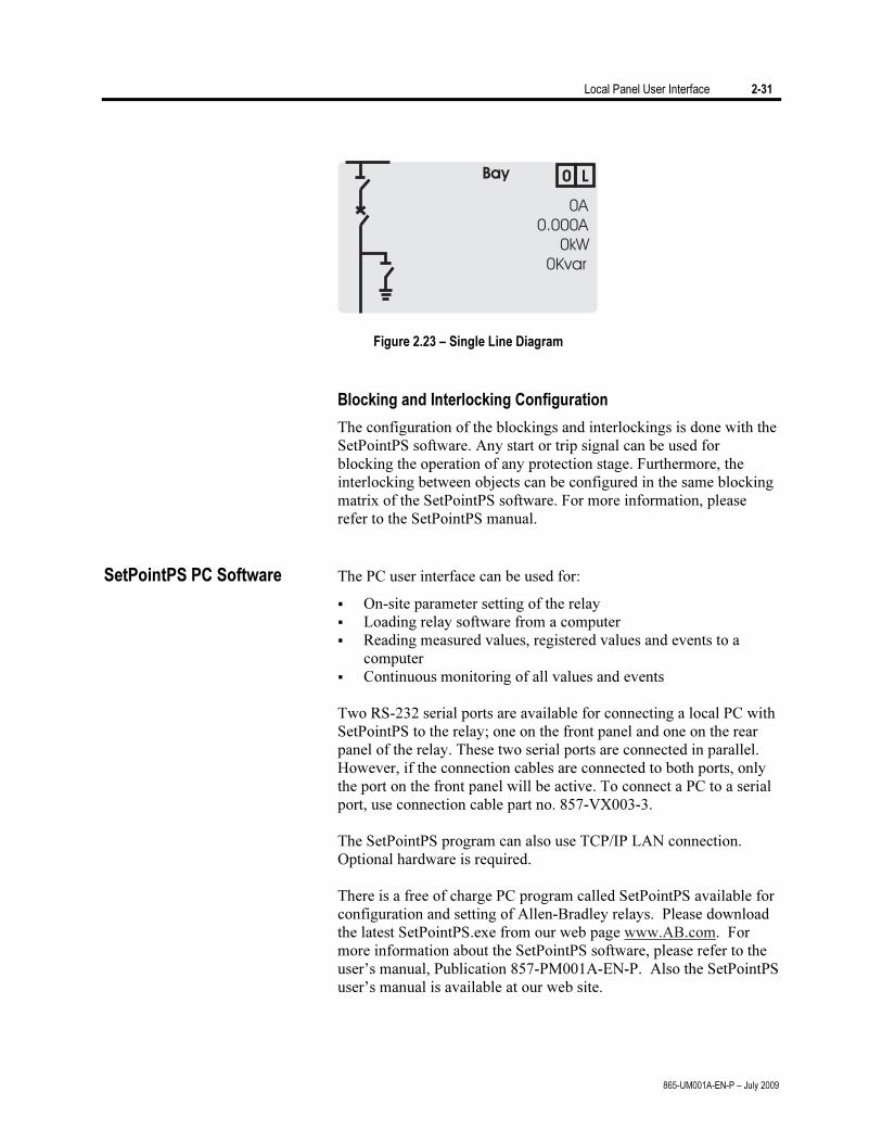
Single Line Diagram Editing
The single-line diagram is drawn with the SetPointPS software. For more information, please refer to the SetPointPS manual.
Configuration and Parameter Setting (cont.)
Local Panel User Interface 2-31
865-UM001A-EN-P – July 2009
Bay 0 L
0A
0.000A
0kW
0Kvar
Figure 2.23 – Single Line Diagram
Blocking and Interlocking Configuration
The configuration of the blockings and interlockings is done with the SetPointPS software. Any start or trip signal can be used for blocking the operation of any protection stage. Furthermore, the interlocking between objects can be configured in the same blocking matrix of the SetPointPS software. For more information, please refer to the SetPointPS manual.
SetPointPS PC Software The PC user interface can be used for:
On-site parameter setting of the relay Loading relay software from a computer Reading measured values, registered values and events to a
computer Continuous monitoring of all values and events
Two RS-232 serial ports are available for connecting a local PC with
SetPointPS to the relay; one on the front panel and one on the rear panel of the relay. These two serial ports are connected in parallel. However, if the connection cables are connected to both ports, only the port on the front panel will be active. To connect a PC to a serial port, use connection cable part no. 857-VX003-3.
The SetPointPS program can also use TCP/IP LAN connection.
Optional hardware is required. There is a free of charge PC program called SetPointPS available for
configuration and setting of Allen-Bradley relays. Please download the latest SetPointPS.exe from our web page www.AB.com. For more information about the SetPointPS software, please refer to the user’s manual, Publication 857-PM001A-EN-P. Also the SetPointPS user’s manual is available at our web site.

2-32 Local Panel User Interface
865-UM001A-EN-P – July 2009
Chapter 3
865-UM001A-EN-P – July 2009
Protection Functions
Each protection stage can independently be enabled or disabled
according to the requirements of the intended application.
The device limits the maximum number of enabled stages to about
30, depending on the type of the stages. For more information,
please see the configuration instructions in Chapter 2 in the first part
of this manual.
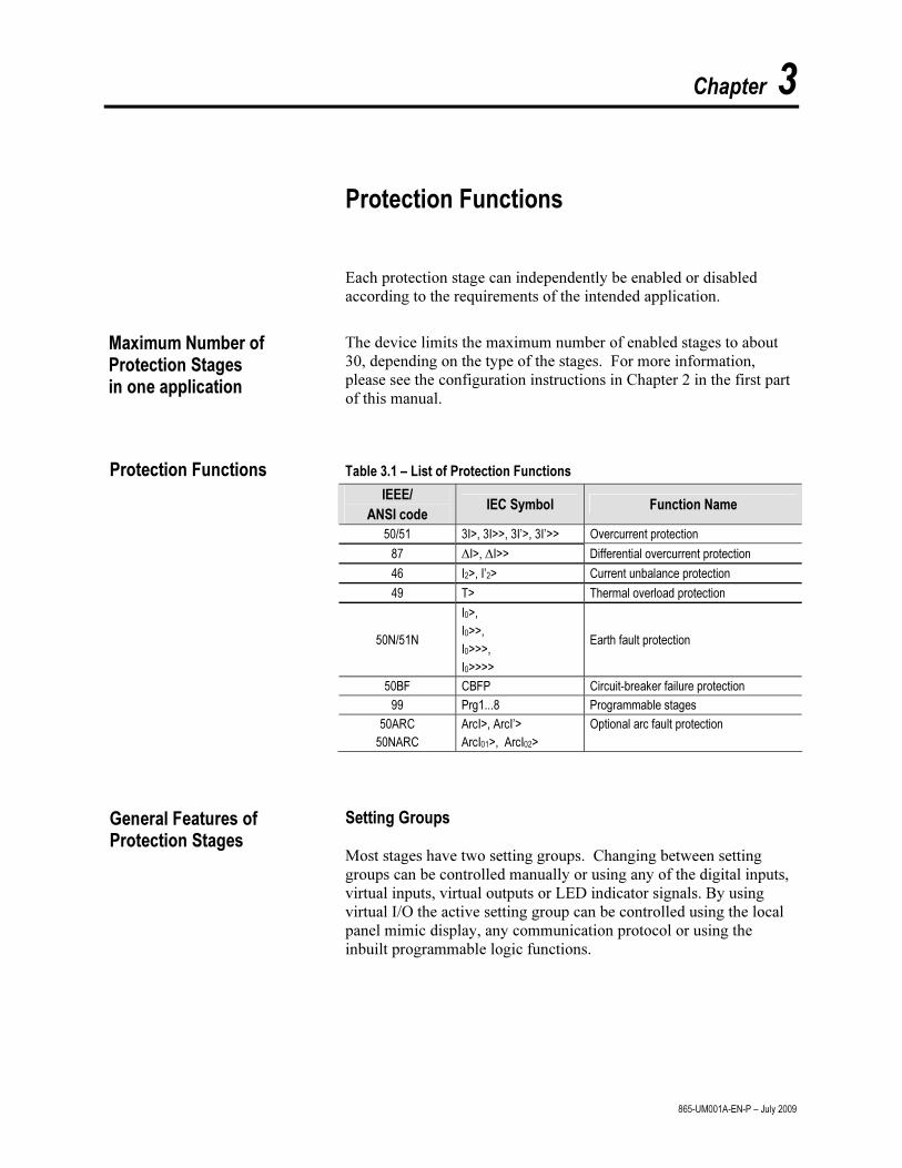
Table 3.1 – List of Protection Functions
IEEE/
ANSI code IEC Symbol Function Name
50/51 3I>, 3I>>, 3I’>, 3I’>> Overcurrent protection
87 ∆I>, ∆I>> Differential overcurrent protection
46 I2>, I’2> Current unbalance protection
49 T> Thermal overload protection
50N/51N
I0>,
I0>>,
I0>>>,
I0>>>>
Earth fault protection
50BF CBFP Circuit-breaker failure protection
99 Prg1...8 Programmable stages
50ARC
50NARC
ArcI>, ArcI’>
ArcI01>, ArcI02>
Optional arc fault protection
Setting Groups
Most stages have two setting groups. Changing between setting
groups can be controlled manually or using any of the digital inputs,
virtual inputs, virtual outputs or LED indicator signals. By using
virtual I/O the active setting group can be controlled using the local
panel mimic display, any communication protocol or using the
inbuilt programmable logic functions.
Maximum Number of Protection Stages in one application
General Features of Protection Stages
Protection Functions
3-2 Protection Functions
865-UM001A-EN-P – July 2009
Forcing Start or Trip Condition for Testing
The status of a protection stage can be one of the followings:
• Ok = ‘–‘ The stage is not detecting any fault.
• Blocked The stage is detecting a fault but blocked by some
reason.
• Start The stage is counting the operation delay.
• Trip The stage has tripped and the fault is still on.
The blocking reason may be an active signal via the block matrix
from other stages, the programmable logic or any digital input.
Some stages also have inbuilt blocking logic. For example an under
frequency stage is blocked if voltage is too low. For more details
about block matrix, see Chapter 5.
Forcing Start or Trip Condition for Testing Purposes
There is a "Force flag" parameter which, when activated, allows
forcing the status of any protection stage to be "start" or "trip" for a
half second. By using this forcing feature any current or voltage
injection to the relay is not necessary to check the output matrix
configuration, to check the wiring from the output relays to the
circuit breaker and also to check that communication protocols are
correctly transferring event information to a SCADA system.
After testing the force flag will automatically reset 5-minute after the
last local panel push button activity.
The force flag also enables forcing of the output relays and forcing
the optional mA outputs.
Start and Trip Signals
Every protection stage has two internal binary output signals: start
and trip. The start signal is issued when a fault has been detected.
The trip signal is issued after the configured operation delay unless
the fault disappears before the end of the delay time.
Output Matrix
Using the output matrix the user connects the internal start and trip
signals to the output relays and indicators. For more details see
Chapter 5.
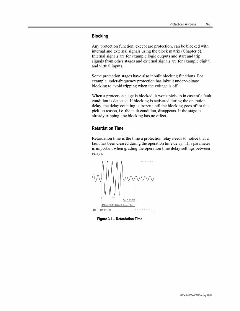
Protection Functions 3-3
865-UM001A-EN-P – July 2009
Blocking
Any protection function, except arc protection, can be blocked with
internal and external signals using the block matrix (Chapter 5).
Internal signals are for example logic outputs and start and trip
signals from other stages and external signals are for example digital
and virtual inputs.
Some protection stages have also inbuilt blocking functions. For
example under-frequency protection has inbuilt under-voltage
blocking to avoid tripping when the voltage is off.
When a protection stage is blocked, it won't pick-up in case of a fault
condition is detected. If blocking is activated during the operation
delay, the delay counting is frozen until the blocking goes off or the
pick-up reason, i.e. the fault condition, disappears. If the stage is
already tripping, the blocking has no effect.
Retardation Time
Retardation time is the time a protection relay needs to notice that a
fault has been cleared during the operation time delay. This parameter
is important when grading the operation time delay settings between
relays.
DELAY SETTING > t + tFAULT RET
TRIP CONTACTS
t < 50 msRET
tFAULT
RetardationTime
Figure 3.1 – Retardation Time
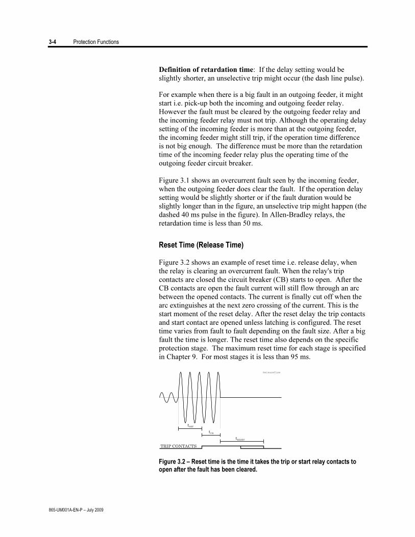
3-4 Protection Functions
865-UM001A-EN-P – July 2009
Definition of retardation time: If the delay setting would be
slightly shorter, an unselective trip might occur (the dash line pulse).
For example when there is a big fault in an outgoing feeder, it might
start i.e. pick-up both the incoming and outgoing feeder relay.
However the fault must be cleared by the outgoing feeder relay and
the incoming feeder relay must not trip. Although the operating delay
setting of the incoming feeder is more than at the outgoing feeder,
the incoming feeder might still trip, if the operation time difference
is not big enough. The difference must be more than the retardation
time of the incoming feeder relay plus the operating time of the
outgoing feeder circuit breaker.
Figure 3.1 shows an overcurrent fault seen by the incoming feeder,
when the outgoing feeder does clear the fault. If the operation delay
setting would be slightly shorter or if the fault duration would be
slightly longer than in the figure, an unselective trip might happen (the
dashed 40 ms pulse in the figure). In Allen-Bradley relays, the
retardation time is less than 50 ms.
Reset Time (Release Time)
Figure 3.2 shows an example of reset time i.e. release delay, when
the relay is clearing an overcurrent fault. When the relay's trip
contacts are closed the circuit breaker (CB) starts to open. After the
CB contacts are open the fault current will still flow through an arc
between the opened contacts. The current is finally cut off when the
arc extinguishes at the next zero crossing of the current. This is the
start moment of the reset delay. After the reset delay the trip contacts
and start contact are opened unless latching is configured. The reset
time varies from fault to fault depending on the fault size. After a big
fault the time is longer. The reset time also depends on the specific
protection stage. The maximum reset time for each stage is specified
in Chapter 9. For most stages it is less than 95 ms.
tSET
tCB
tRESET
TRIP CONTACTS
ReleaseTime
Figure 3.2 – Reset time is the time it takes the trip or start relay contacts to
open after the fault has been cleared.
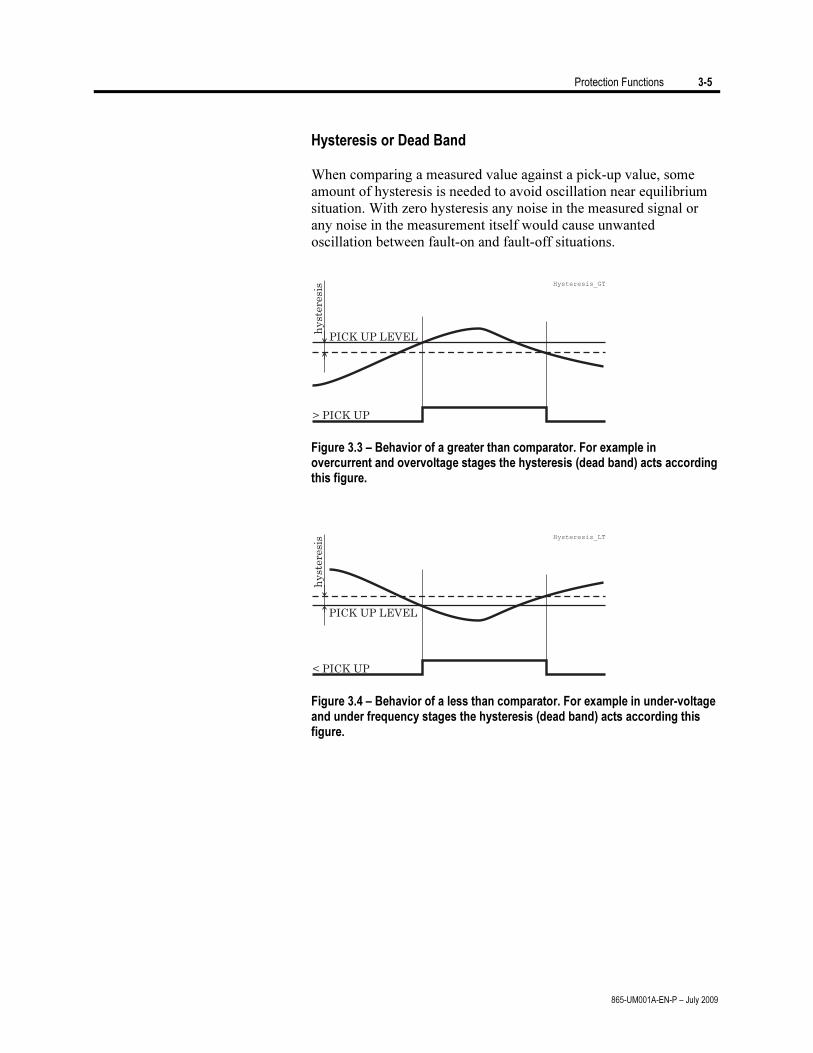
Protection Functions 3-5
865-UM001A-EN-P – July 2009
Hysteresis or Dead Band
When comparing a measured value against a pick-up value, some
amount of hysteresis is needed to avoid oscillation near equilibrium
situation. With zero hysteresis any noise in the measured signal or
any noise in the measurement itself would cause unwanted
oscillation between fault-on and fault-off situations.
> PICK UP
PICK UP LEVEL
hyst
eres
is
Hysteresis_GT
Figure 3.3 – Behavior of a greater than comparator. For example in
overcurrent and overvoltage stages the hysteresis (dead band) acts according this figure.
< PICK UP
PICK UP LEVEL
hyst
eres
is
Hysteresis_LT
Figure 3.4 – Behavior of a less than comparator. For example in under-voltage
and under frequency stages the hysteresis (dead band) acts according this figure.
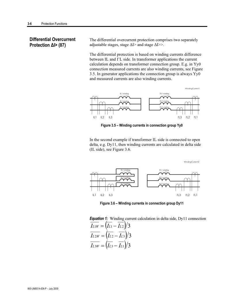
3-6 Protection Functions
865-UM001A-EN-P – July 2009
The differential overcurrent protection comprises two separately
adjustable stages, stage ΔI> and stage ΔI>>.
The differential protection is based on winding currents difference
between IL and I’L side. In transformer applications the current
calculation depends on transformer connection group. E.g. in Yy0
connection measured currents are also winding currents, see Figure
3.5. In generator applications the connection group is always Yy0
and measured currents are also winding currents.
Figure 3.5 – Winding currents in connection group Yy0
In the second example if transformer IL side is connected to open
delta, e.g. Dy11, then winding currents are calculated in delta side
(IL side), see Figure 3.6.
Figure 3.6 – Winding currents in connection group Dy11
Equation 1: Winding current calculation in delta side, Dy11 connection
( ))(
( ) 33
3
133
322
211
LLWL
LLWL
LLWL
III
III
III
−=
−=
−=
Differential Overcurrent Protection ΔI> (87)
Protection Functions 3-7
865-UM001A-EN-P – July 2009
Equation 2: Winding currents in star side, Dy11 connection
33
22
11
''
''
''
LWL
LWL
LWL
II
II
II
=
=
=
Equation 3: Bias current
2
'WW
b
II
I
+
=
Equation 4: Differential current
WWd
III '+=
Bias current calculation is only used in protection stage ΔI>. Bias
current describes the average current flow in transformer. Bias and
differential currents are calculated individually for each phase.
If transformer is earthed, e.g. connection group Dyn11, then zero
current must be compensated before differential and bias current
calculation. Zero current compensation can be selected individually
for IL and I’L side.
Table 3.2 describes connection group and zero current compensation
for different connection groups. If protection area is only generator
then connection group setting is always Yy0, see Table 3.3. Also the
settings of Un and U’n are set to be the same, e.g. generator nominal
voltage.
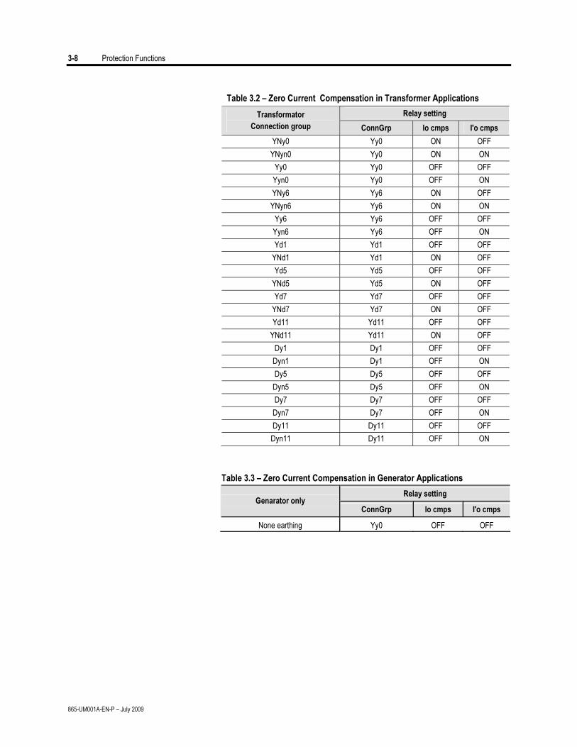
3-8 Protection Functions
865-UM001A-EN-P – July 2009
Table 3.2 – Zero Current Compensation in Transformer Applications
Relay setting Transformator
Connection group ConnGrp Io cmps I'o cmps
YNy0 Yy0 ON OFF
YNyn0 Yy0 ON ON
Yy0 Yy0 OFF OFF
Yyn0 Yy0 OFF ON
YNy6 Yy6 ON OFF
YNyn6 Yy6 ON ON
Yy6 Yy6 OFF OFF
Yyn6 Yy6 OFF ON
Yd1 Yd1 OFF OFF
YNd1 Yd1 ON OFF
Yd5 Yd5 OFF OFF
YNd5 Yd5 ON OFF
Yd7 Yd7 OFF OFF
YNd7 Yd7 ON OFF
Yd11 Yd11 OFF OFF
YNd11 Yd11 ON OFF
Dy1 Dy1 OFF OFF
Dyn1 Dy1 OFF ON
Dy5 Dy5 OFF OFF
Dyn5 Dy5 OFF ON
Dy7 Dy7 OFF OFF
Dyn7 Dy7 OFF ON
Dy11 Dy11 OFF OFF
Dyn11 Dy11 OFF ON
Table 3.3 – Zero Current Compensation in Generator Applications
Relay setting Genarator only
ConnGrp Io cmps I'o cmps
None earthing Yy0 OFF OFF
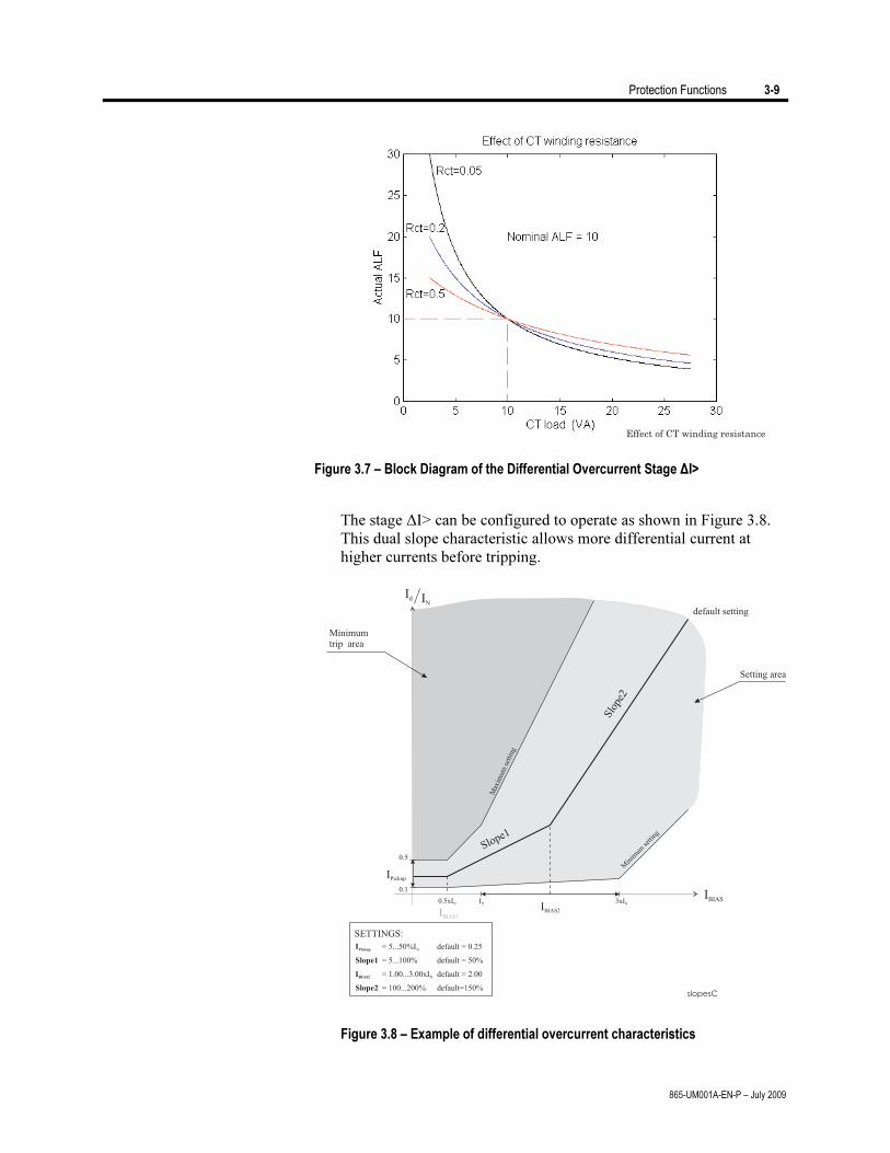
Protection Functions 3-9
865-UM001A-EN-P – July 2009
Figure 3.7 – Block Diagram of the Differential Overcurrent Stage ΔI>
The stage ΔI> can be configured to operate as shown in Figure 3.8.
This dual slope characteristic allows more differential current at
higher currents before tripping.
Figure 3.8 – Example of differential overcurrent characteristics
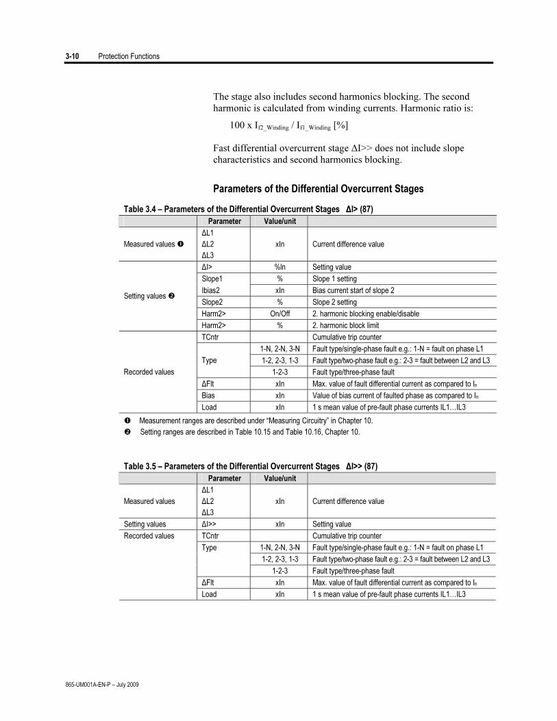
3-10 Protection Functions
865-UM001A-EN-P – July 2009
The stage also includes second harmonics blocking. The second
harmonic is calculated from winding currents. Harmonic ratio is:
100 x If2_Winding / If1_Winding [%]
Fast differential overcurrent stage ΔI>> does not include slope
characteristics and second harmonics blocking.
Parameters of the Differential Overcurrent Stages
Table 3.4 – Parameters of the Differential Overcurrent Stages ΔI> (87)
Parameter Value/unit
Measured values
ΔL1
ΔL2
ΔL3
xIn Current difference value
ΔI> %ln Setting value
Slope1 % Slope 1 setting
Ibias2 xIn Bias current start of slope 2
Slope2 % Slope 2 setting
Harm2> On/Off 2. harmonic blocking enable/disable
Setting values
Harm2> % 2. harmonic block limit
TCntr Cumulative trip counter
1-N, 2-N, 3-N Fault type/single-phase fault e.g.: 1-N = fault on phase L1
1-2, 2-3, 1-3 Fault type/two-phase fault e.g.: 2-3 = fault between L2 and L3 Type
1-2-3 Fault type/three-phase fault
ΔFlt xIn Max. value of fault differential current as compared to In
Bias xIn Value of bias current of faulted phase as compared to In
Recorded values
Load xIn 1 s mean value of pre-fault phase currents IL1…IL3
Measurement ranges are described under “Measuring Circuitry” in Chapter 10.
Setting ranges are described in Table 10.15 and Table 10.16, Chapter 10.
Table 3.5 – Parameters of the Differential Overcurrent Stages ΔI>> (87)
Parameter Value/unit
Measured values
ΔL1
ΔL2
ΔL3
xIn Current difference value
Setting values ΔI>> xIn Setting value
TCntr Cumulative trip counter
1-N, 2-N, 3-N Fault type/single-phase fault e.g.: 1-N = fault on phase L1
1-2, 2-3, 1-3 Fault type/two-phase fault e.g.: 2-3 = fault between L2 and L3
Type
1-2-3 Fault type/three-phase fault
ΔFlt xIn Max. value of fault differential current as compared to In
Recorded values
Load xIn 1 s mean value of pre-fault phase currents IL1…IL3
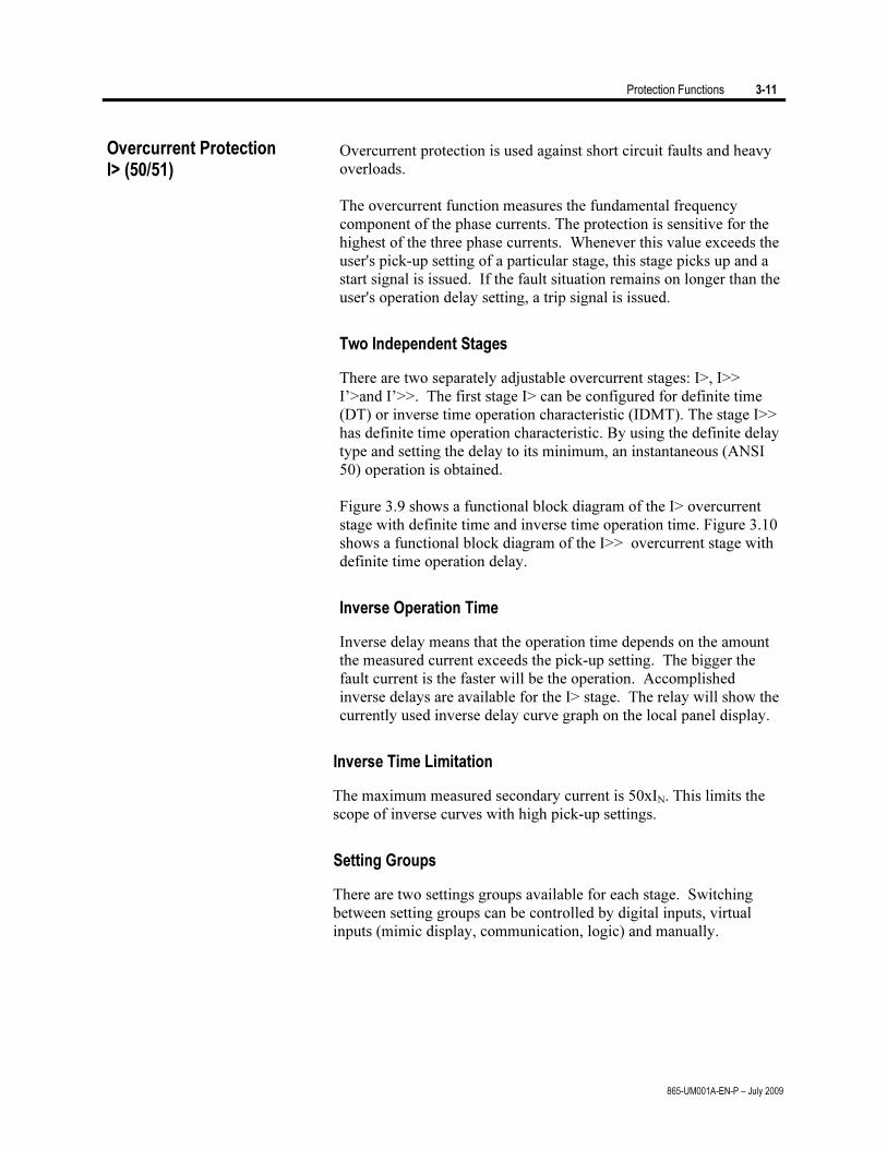
Protection Functions 3-11
865-UM001A-EN-P – July 2009
Overcurrent protection is used against short circuit faults and heavy
overloads.
The overcurrent function measures the fundamental frequency
component of the phase currents. The protection is sensitive for the
highest of the three phase currents. Whenever this value exceeds the
user's pick-up setting of a particular stage, this stage picks up and a
start signal is issued. If the fault situation remains on longer than the
user's operation delay setting, a trip signal is issued.
Two Independent Stages
There are two separately adjustable overcurrent stages: I>, I>>
I’>and I’>>. The first stage I> can be configured for definite time
(DT) or inverse time operation characteristic (IDMT). The stage I>>
has definite time operation characteristic. By using the definite delay
type and setting the delay to its minimum, an instantaneous (ANSI
50) operation is obtained.
Figure 3.9 shows a functional block diagram of the I> overcurrent
stage with definite time and inverse time operation time. Figure 3.10
shows a functional block diagram of the I>> overcurrent stage with
definite time operation delay.
Inverse Operation Time
Inverse delay means that the operation time depends on the amount
the measured current exceeds the pick-up setting. The bigger the
fault current is the faster will be the operation. Accomplished
inverse delays are available for the I> stage. The relay will show the
currently used inverse delay curve graph on the local panel display.
Inverse Time Limitation
The maximum measured secondary current is 50xIN. This limits the
scope of inverse curves with high pick-up settings.
Setting Groups
There are two settings groups available for each stage. Switching
between setting groups can be controlled by digital inputs, virtual
inputs (mimic display, communication, logic) and manually.
Overcurrent Protection I> (50/51)
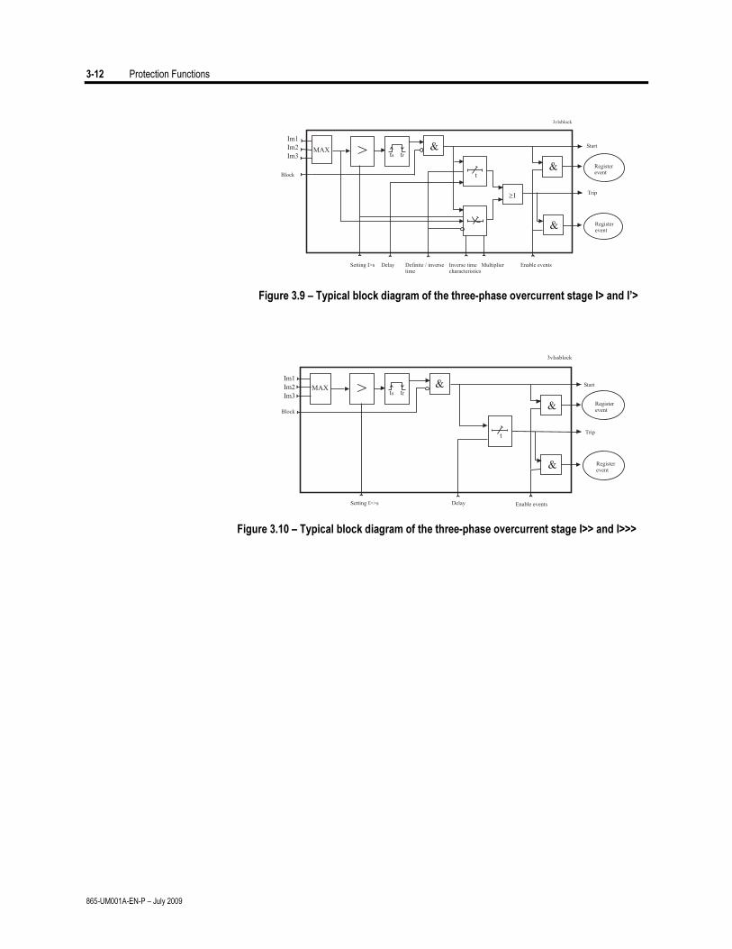
3-12 Protection Functions
865-UM001A-EN-P – July 2009
Figure 3.9 – Typical block diagram of the three-phase overcurrent stage I> and I’>
Figure 3.10 – Typical block diagram of the three-phase overcurrent stage I>> and I>>>
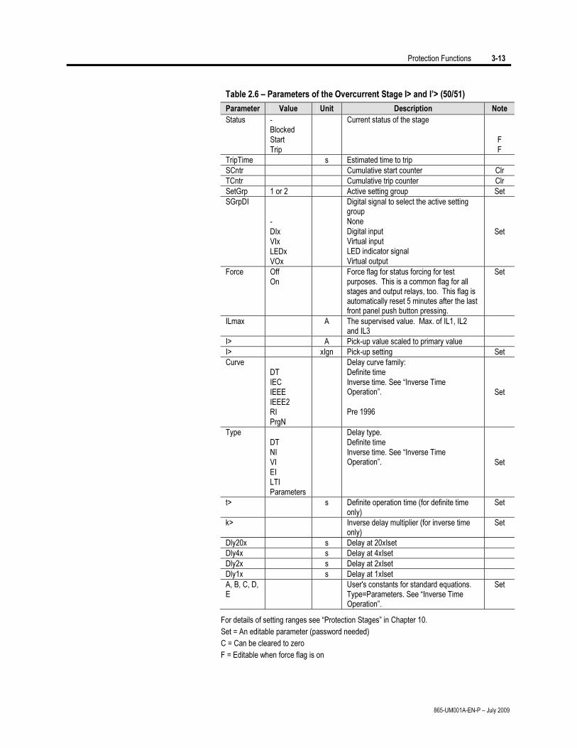
Protection Functions 3-13
865-UM001A-EN-P – July 2009
Table 2.6 – Parameters of the Overcurrent Stage I> and I’> (50/51)
Parameter Value Unit Description Note
Status - Blocked Start Trip
Current status of the stage
F F
TripTime s Estimated time to trip
SCntr Cumulative start counter Clr
TCntr Cumulative trip counter Clr
SetGrp 1 or 2 Active setting group Set
SGrpDI - DIx VIx LEDx VOx
Digital signal to select the active setting group None Digital input Virtual input LED indicator signal Virtual output
Set
Force Off On
Force flag for status forcing for test purposes. This is a common flag for all stages and output relays, too. This flag is automatically reset 5 minutes after the last front panel push button pressing.
Set
ILmax A The supervised value. Max. of IL1, IL2 and IL3
I> A Pick-up value scaled to primary value
I> xIgn Pick-up setting Set
Curve DT IEC IEEE IEEE2 RI PrgN
Delay curve family: Definite time Inverse time. See “Inverse Time Operation”. Pre 1996
Set
Type DT NI VI EI LTI Parameters
Delay type. Definite time Inverse time. See “Inverse Time Operation”.
Set
t> s Definite operation time (for definite time only)
Set
k> Inverse delay multiplier (for inverse time only)
Set
Dly20x s Delay at 20xIset
Dly4x s Delay at 4xIset
Dly2x s Delay at 2xIset
Dly1x s Delay at 1xIset
A, B, C, D, E
User's constants for standard equations. Type=Parameters. See “Inverse Time Operation”.
Set
For details of setting ranges see “Protection Stages” in Chapter 10.
Set = An editable parameter (password needed)
C = Can be cleared to zero
F = Editable when force flag is on
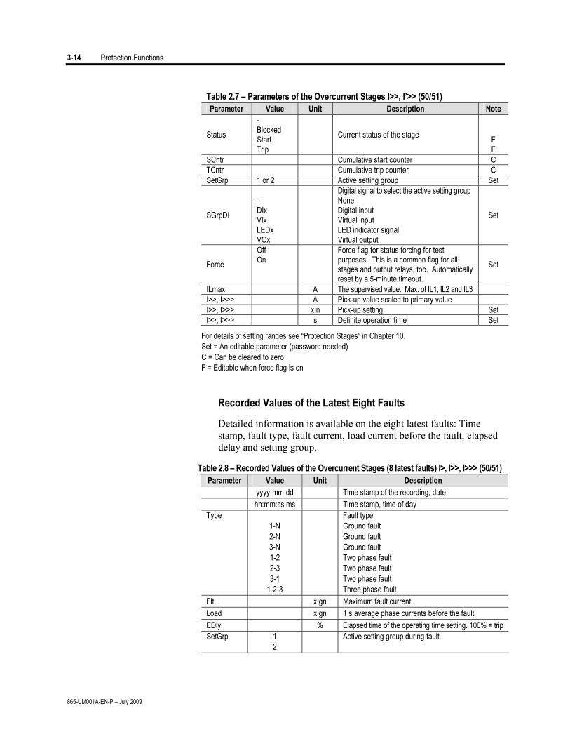
3-14 Protection Functions
865-UM001A-EN-P – July 2009
Table 2.7 – Parameters of the Overcurrent Stages I>>, I’>> (50/51)
Parameter Value Unit Description Note
Status
- Blocked Start Trip
Current status of the stage
F F
SCntr Cumulative start counter C
TCntr Cumulative trip counter C
SetGrp 1 or 2 Active setting group Set
SGrpDI
- DIx VIx LEDx VOx
Digital signal to select the active setting group None Digital input Virtual input LED indicator signal Virtual output
Set
Force
Off On
Force flag for status forcing for test purposes. This is a common flag for all stages and output relays, too. Automatically reset by a 5-minute timeout.
Set
ILmax A The supervised value. Max. of IL1, IL2 and IL3
I>>, I>>> A Pick-up value scaled to primary value
I>>, I>>> xIn Pick-up setting Set
t>>, t>>> s Definite operation time Set
For details of setting ranges see “Protection Stages” in Chapter 10.
Set = An editable parameter (password needed)
C = Can be cleared to zero
F = Editable when force flag is on
Recorded Values of the Latest Eight Faults
Detailed information is available on the eight latest faults: Time
stamp, fault type, fault current, load current before the fault, elapsed
delay and setting group.
Table 2.8 – Recorded Values of the Overcurrent Stages (8 latest faults) I>, I>>, I>>> (50/51)
Parameter Value Unit Description
yyyy-mm-dd Time stamp of the recording, date
hh:mm:ss.ms Time stamp, time of day
Type
1-N
2-N
3-N
1-2
2-3
3-1
1-2-3
Fault type
Ground fault
Ground fault
Ground fault
Two phase fault
Two phase fault
Two phase fault
Three phase fault
Flt xIgn Maximum fault current
Load xIgn 1 s average phase currents before the fault
EDly % Elapsed time of the operating time setting. 100% = trip
SetGrp 1
2
Active setting group during fault

Protection Functions 3-15
865-UM001A-EN-P – July 2009
The current unbalance stage protects against unbalanced phase
currents and single phasing. The protection is based on the negative
sequence current.
Both definite time and inverse time characteristics are available. The
inverse delay is based on Equation 5. Only the base frequency com-
ponents of the phase currents are used to calculate the negative
sequence value I2.
Inverse Delay
The inverse delay is based on the following equation.
Equation 5
2
2
2
2
1
KI
I
Kt
N
−⎟⎟⎠
⎞⎜⎜⎝
⎛= , where
t = Operation time
K1 = Delay multiplier
I2 = Measured and calculated negative sequence
phase current of fundamental frequency.
IN = Rated current
K2 = Pick-up setting I2> in pu. The maximum
allowed degree of unbalance.
Example:
K1 = 15 s
I2 = 22.9 % = 0.229 xIN
K2 = 5 % = 0.05 xIN
4.300
05.01
229.0
15
2
2=
−⎟⎠
⎞⎜⎝
⎛=t
The operation time in this example will be five minutes.
More Stages (Definite Time Delay only)
If more than one definite time delay stages are needed for current
unbalance protection, the freely programmable stages can be used
(Chapter 2).
Setting Groups
There are two settings groups available. Switching between setting
groups can be controlled by digital inputs, virtual inputs (mimic
display, communication, logic) and manually.
Current unbalance protection I2>, I’2> (46)
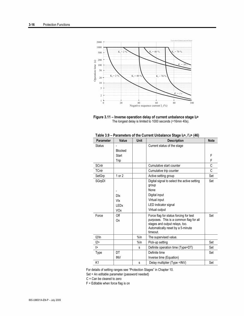
3-16 Protection Functions
865-UM001A-EN-P – July 2009
01
10
100
1000
2
20
200
2000
5
50
500
20Negative sequence current I (%)2
CurrentUnbalanceChar
Op
erat
ion
tim
e(s
)
40 60 80 100
K = 1 s1
K = 50 s1
K = 2 %2
K = 2 %2
K = 40 %2
K = 40 %2
K = 70 %2
K = 70 %2
Figure 3.11 – Inverse operation delay of current unbalance stage I2> The longest delay is limited to 1000 seconds (=16min 40s).
Table 3.9 – Parameters of the Current Unbalance Stage I2>, I’2> (46)
Parameter Value Unit Description Note
Status -
Blocked
Start
Trip
Current status of the stage
F
F
SCntr Cumulative start counter C
TCntr Cumulative trip counter C
SetGrp 1 or 2 Active setting group Set
SGrpDI
-
DIx
VIx
LEDx
VOx
Digital signal to select the active setting group
None
Digital input
Virtual input
LED indicator signal
Virtual output
Set
Force Off
On
Force flag for status forcing for test purposes. This is a common flag for all stages and output relays, too. Automatically reset by a 5-minute timeout.
Set
I2/In %In The supervised value.
I2> %In Pick-up setting Set
t> s Definite operation time (Type=DT) Set
Type DT
INV
Definite time
Inverse time (Equation)
Set
K1 s Delay multiplier (Type =INV) Set
For details of setting ranges see “Protection Stages” in Chapter 10.
Set = An editable parameter (password needed)
C = Can be cleared to zero
F = Editable when force flag is on
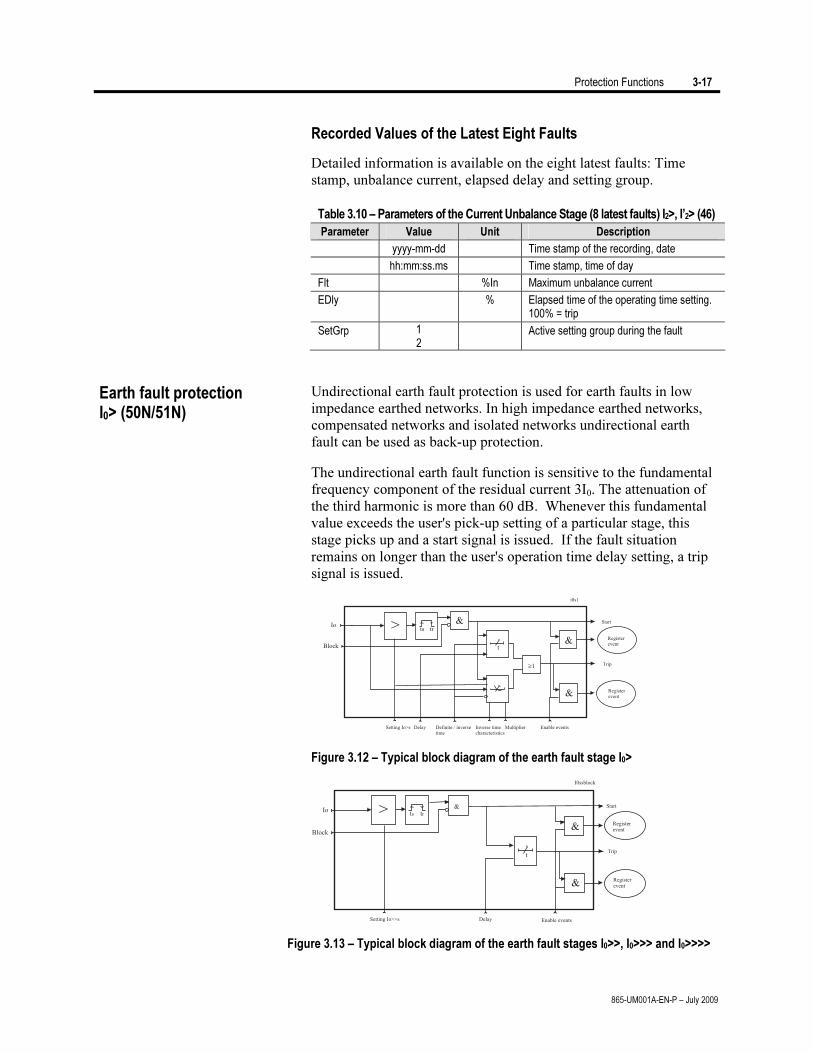
Protection Functions 3-17
865-UM001A-EN-P – July 2009
Recorded Values of the Latest Eight Faults
Detailed information is available on the eight latest faults: Time
stamp, unbalance current, elapsed delay and setting group.
Table 3.10 – Parameters of the Current Unbalance Stage (8 latest faults) I2>, I’2> (46)
Parameter Value Unit Description
yyyy-mm-dd Time stamp of the recording, date
hh:mm:ss.ms Time stamp, time of day
Flt %In Maximum unbalance current
EDly % Elapsed time of the operating time setting. 100% = trip
SetGrp 1 2
Active setting group during the fault
Undirectional earth fault protection is used for earth faults in low
impedance earthed networks. In high impedance earthed networks,
compensated networks and isolated networks undirectional earth
fault can be used as back-up protection.
The undirectional earth fault function is sensitive to the fundamental
frequency component of the residual current 3I0. The attenuation of
the third harmonic is more than 60 dB. Whenever this fundamental
value exceeds the user's pick-up setting of a particular stage, this
stage picks up and a start signal is issued. If the fault situation
remains on longer than the user's operation time delay setting, a trip
signal is issued.
Figure 3.12 – Typical block diagram of the earth fault stage I0>
Figure 3.13 – Typical block diagram of the earth fault stages I0>>, I0>>> and I0>>>>
Earth fault protection I0> (50N/51N)

3-18 Protection Functions
865-UM001A-EN-P – July 2009
Figure 3.12 shows a functional block diagram of the I0> earth
overcurrent stage with definite time and inverse time operation time.
Figure 3.13 shows a functional block diagram of the I0>>, I0>>> and
I0>>>> earth fault stages with definite time operation delay.
Input Signal Selection
Each stage can be connected to supervise any of the following inputs
and signals:
• Input I01 for all networks other than rigidly earthed
• Input I02 for all networks other than rigidly earthed
• Calculated signal I0Calc for rigidly and low impedance earthed
networks. I0Calc = IL1 + IL2 + IL3
• Calculated signal I’0Calc for rigidly and low impedance earthed
networks. I’0Calc = I’L1 + I’L2 + I’L3
Additionally the stage I0> have two more input signal alternatives to
measure current peaks to detect a restriking intermittent earth fault:
• I01Peak to measure the peak value of input I01
• I02Peak to measure the peak value of input I02
Intermittent Earth Fault Detection
Short earth faults make the protection to start (pick up), but will not
cause trip. When starting happens often enough, such intermittent
faults can be cleared using the intermittent time setting.
When a new start happens within the set intermittent time, the
operation delay counter is not cleared between adjacent faults and
finally the stage will trip. By using input signals I01Peak or I02Peak a
single one-millisecond current peak is enough to start the stage and
increase the delay counter by 20 ms. For example if the operating
time is 120 ms, and the time between two peaks does not exceed the
intermittent time setting, the sixth peak will cause a trip.
Four Independent Undirectional Earth Fault Overcurrent Stages
There are four separately adjustable earth fault stages: I0>, I0>>,
I0>>>, and I0>>>>. The first stage I0> can be configured for definite
time (DT) or inverse time operation characteristic (IDMT). The other
stages have definite time operation characteristic. By using the definite
delay type and setting the delay to its minimum, an instantaneous
(ANSI 50N) operation is obtained.
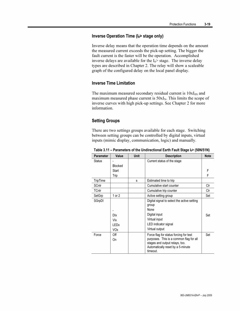
Protection Functions 3-19
865-UM001A-EN-P – July 2009
Inverse Operation Time (I0> stage only)
Inverse delay means that the operation time depends on the amount
the measured current exceeds the pick-up setting. The bigger the
fault current is the faster will be the operation. Accomplished
inverse delays are available for the I0> stage. The inverse delay
types are described in Chapter 2. The relay will show a scaleable
graph of the configured delay on the local panel display.
Inverse Time Limitation
The maximum measured secondary residual current is 10xI0N and
maximum measured phase current is 50xIN. This limits the scope of
inverse curves with high pick-up settings. See Chapter 2 for more
information.
Setting Groups
There are two settings groups available for each stage. Switching
between setting groups can be controlled by digital inputs, virtual
inputs (mimic display, communication, logic) and manually.
Table 3.11 – Parameters of the Undirectional Earth Fault Stage I0> (50N/51N)
Parameter Value Unit Description Note
Status -
Blocked
Start
Trip
Current status of the stage
F
F
TripTime s Estimated time to trip
SCntr Cumulative start counter Clr
TCntr Cumulative trip counter Clr
SetGrp 1 or 2 Active setting group Set
SGrpDI
-
DIx
VIx
LEDx
VOx
Digital signal to select the active setting group
None
Digital input
Virtual input
LED indicator signal
Virtual output
Set
Force Off
On
Force flag for status forcing for test purposes. This is a common flag for all stages and output relays, too. Automatically reset by a 5-minute timeout.
Set
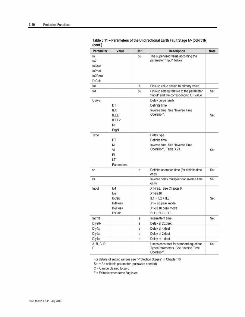
3-20 Protection Functions
865-UM001A-EN-P – July 2009
Table 3.11 – Parameters of the Undirectional Earth Fault Stage I0> (50N/51N) (cont.)
Parameter Value Unit Description Note
Io
Io2
IoCalc
IoPeak
Io2Peak
I’oCalc
pu The supervised value according the parameter "Input" below.
Io> A Pick-up value scaled to primary value
Io> pu Pick-up setting relative to the parameter "Input" and the corresponding CT value
Set
Curve
DT
IEC
IEEE
IEEE2
RI
PrgN
Delay curve family:
Definite time
Inverse time. See “Inverse Time Operation”.
Set
Type
DT
NI
VI
EI
LTI
Parameters
Delay type.
Definite time
Inverse time. See “Inverse Time Operation”, Table 3.23.
Set
t> s Definite operation time (for definite time only)
Set
k> Inverse delay multiplier (for inverse time only)
Set
Input Io1
Io2
IoCalc
Io1Peak
Io2Peak
I’oCalc
X1-7&8. See Chapter 9.
X1-9&10
IL1 + IL2 + IL3
X1-7&8 peak mode
X1-9&10 peak mode
I’L1 + I’L2 + I’L3
Set
Intrmt s Intermittent time Set
Dly20x s Delay at 20xIset
Dly4x s Delay at 4xIset
Dly2x s Delay at 2xIset
Dly1x s Delay at 1xIset
A, B, C, D, E
User's constants for standard equations. Type=Parameters. See “Inverse Time Operation”.
Set
For details of setting ranges see “Protection Stages” in Chapter 10.
Set = An editable parameter (password needed)
C = Can be cleared to zero
F = Editable when force flag is on
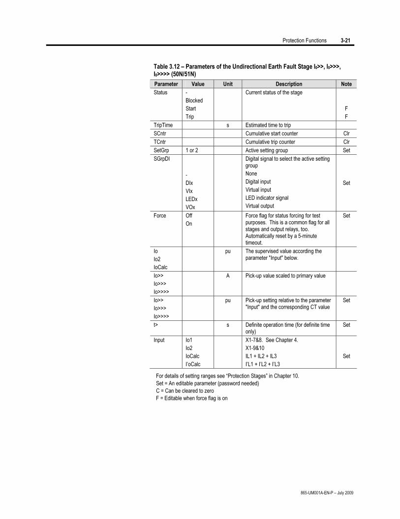
Protection Functions 3-21
865-UM001A-EN-P – July 2009
Table 3.12 – Parameters of the Undirectional Earth Fault Stage I0>>, I0>>>, I0>>>> (50N/51N)
Parameter Value Unit Description Note
Status -
Blocked
Start
Trip
Current status of the stage
F
F
TripTime s Estimated time to trip
SCntr Cumulative start counter Clr
TCntr Cumulative trip counter Clr
SetGrp 1 or 2 Active setting group Set
SGrpDI
-
DIx
VIx
LEDx
VOx
Digital signal to select the active setting group
None
Digital input
Virtual input
LED indicator signal
Virtual output
Set
Force Off
On
Force flag for status forcing for test purposes. This is a common flag for all stages and output relays, too. Automatically reset by a 5-minute timeout.
Set
Io
Io2
IoCalc
pu The supervised value according the parameter "Input" below.
Io>>
Io>>>
Io>>>>
A Pick-up value scaled to primary value
Io>>
Io>>>
Io>>>>
pu Pick-up setting relative to the parameter "Input" and the corresponding CT value
Set
t> s Definite operation time (for definite time only)
Set
Input Io1
Io2
IoCalc
I’oCalc
X1-7&8. See Chapter 4.
X1-9&10
IL1 + IL2 + IL3
I’L1 + I’L2 + I’L3
Set
For details of setting ranges see “Protection Stages” in Chapter 10.
Set = An editable parameter (password needed)
C = Can be cleared to zero
F = Editable when force flag is on
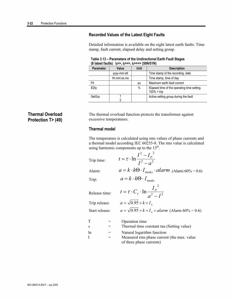
3-22 Protection Functions
865-UM001A-EN-P – July 2009
Recorded Values of the Latest Eight Faults
Detailed information is available on the eight latest earth faults: Time
stamp, fault current, elapsed delay and setting group.
Table 3.13 – Parameters of the Undirectional Earth Fault Stages (8 latest faults) I0>>, I0>>>, I0>>>> (50N/51N)
Parameter Value Unit Description
yyyy-mm-dd Time stamp of the recording, date
hh:mm:ss.ms Time stamp, time of day
Flt pu Maximum earth fault current
EDly % Elapsed time of the operating time setting. 100% = trip
SetGrp 1 2
Active setting group during the fault
The thermal overload function protects the transformer against
excessive temperatures.
Thermal model
The temperature is calculated using rms values of phase currents and
a thermal model according IEC 60255-8. The rms value is calculated
using harmonic components up to the 15th.
Trip time: 22
22
lnaI
IIt
P
−
−
⋅=τ
Alarm: alarmIkkae⋅⋅Θ⋅=
mod (Alarm 60% = 0.6)
Trip: e
Ikkamod
⋅Θ⋅=
Release time: 22
2
lnIa
ICt
P
−
⋅⋅=τ
τ
Trip release: nIka ××= 95.0
Start release: alarmIkan×××= 95.0 (Alarm 60% = 0.6)
T = Operation time
τ = Thermal time constant tau (Setting value)
ln = Natural logarithm function
I = Measured rms phase current (the max. value
of three phase currents)
Thermal Overload Protection T> (49)
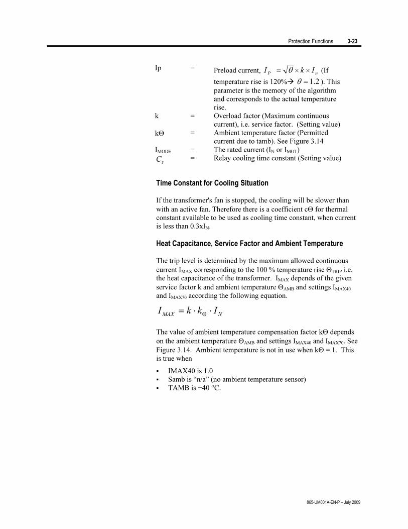
Protection Functions 3-23
865-UM001A-EN-P – July 2009
Ip = Preload current, nPIkI ××= θ (If
temperature rise is 120% 2.1=θ ). This
parameter is the memory of the algorithm
and corresponds to the actual temperature
rise.
k = Overload factor (Maximum continuous
current), i.e. service factor. (Setting value)
kΘ = Ambient temperature factor (Permitted
current due to tamb). See Figure 3.14
IMODE = The rated current (IN or IMOT)
τC = Relay cooling time constant (Setting value)
Time Constant for Cooling Situation
If the transformer's fan is stopped, the cooling will be slower than
with an active fan. Therefore there is a coefficient cΘ for thermal
constant available to be used as cooling time constant, when current
is less than 0.3xIN.
Heat Capacitance, Service Factor and Ambient Temperature
The trip level is determined by the maximum allowed continuous
current IMAX corresponding to the 100 % temperature rise ΘTRIP i.e.
the heat capacitance of the transformer. IMAX depends of the given
service factor k and ambient temperature ΘAMB and settings IMAX40
and IMAX70 according the following equation.
NMAXIkkI ⋅⋅=
Θ
The value of ambient temperature compensation factor kΘ depends
on the ambient temperature ΘAMB and settings IMAX40 and IMAX70. See
Figure 3.14. Ambient temperature is not in use when kΘ = 1. This
is true when
IMAX40 is 1.0
Samb is “n/a” (no ambient temperature sensor)
TAMB is +40 °C.
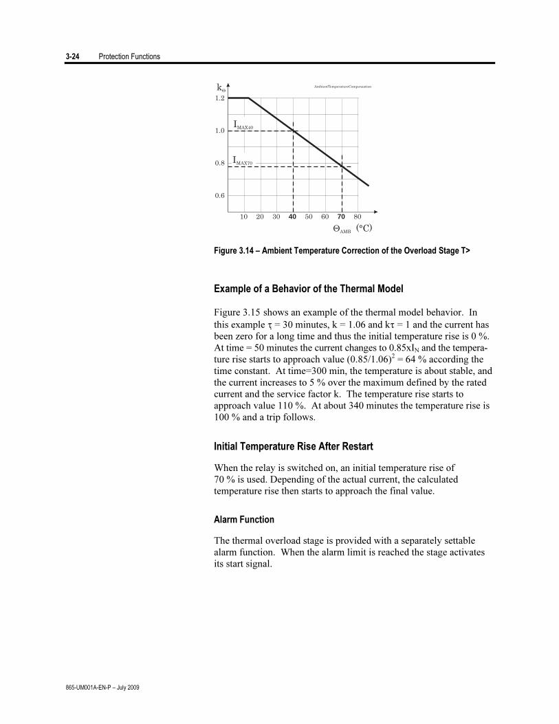
3-24 Protection Functions
865-UM001A-EN-P – July 2009
k
IMAX70
IMAX40
AMB (°C)
AmbientTemperatureCompensation
0.6
10 20 30 40 50 60 70 80
0.8
1.0
1.2
Figure 3.14 – Ambient Temperature Correction of the Overload Stage T>
Example of a Behavior of the Thermal Model
Figure 3.15 shows an example of the thermal model behavior. In
this example τ = 30 minutes, k = 1.06 and kτ = 1 and the current has
been zero for a long time and thus the initial temperature rise is 0 %.
At time = 50 minutes the current changes to 0.85xIN and the tempera-
ture rise starts to approach value (0.85/1.06)2 = 64 % according the
time constant. At time=300 min, the temperature is about stable, and
the current increases to 5 % over the maximum defined by the rated
current and the service factor k. The temperature rise starts to
approach value 110 %. At about 340 minutes the temperature rise is
100 % and a trip follows.
Initial Temperature Rise After Restart
When the relay is switched on, an initial temperature rise of
70 % is used. Depending of the actual current, the calculated
temperature rise then starts to approach the final value.
Alarm Function
The thermal overload stage is provided with a separately settable
alarm function. When the alarm limit is reached the stage activates
its start signal.
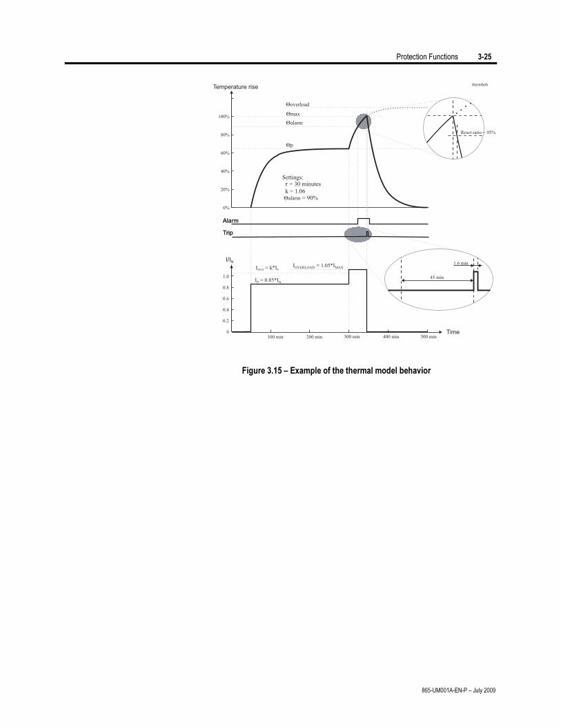
Protection Functions 3-25
865-UM001A-EN-P – July 2009
Figure 3.15 – Example of the thermal model behavior

3-26 Protection Functions
865-UM001A-EN-P – July 2009
Table 3.14 – Parameters of the Thermal Overload Stage T> (49)
Parameter Value Unit Description Note
Status -
Blocked
Start
Trip
Current status of the stage
F
F
Time hh:mm:ss Estimated time to trip
SCntr Cumulative start counter C
TCntr Cumulative trip counter C
Force Off
On
Force flag for status forcing for test purposes. This is a common flag for all stages and output relays, too. Automatically reset by a 5-minute timeout.
Set
T % Calculated temperature rise. Trip limit is 100 %.
F
MaxRMS Arms Measured current. Highest of the three phases.
Imax A kxIgn. Current corresponding to the 100 % temperature rise.
k> xIn Allowed overload (service factor) Set
Alarm % Alarm level Set
tau min Thermal time constant Set
ctau xtau Coefficient for cooling time constant. Default = 1.0
Set
kTamb xIn Ambient temperature corrected max. allowed continuous current
Imax40 %In Allowed load at Tamb +40 °C. Default = 100 %.
Set
Imax70 %In Allowed load at Tamb +70 °C. Set
Tamb °C Ambient temperature. Editable
Samb=n/a. Default = +40 °C
Set
Samb
n/a
ExtAI1...16
Sensor for ambient temperature
No sensor in use for Tamb
External Analogue input 1...16
Set
For details of setting ranges see “Protection Stages” in Chapter 10.
Set = An editable parameter (password needed)
C = Can be cleared to zero
F = Editable when force flag is on
The circuit breaker failure protection can be used to trip any upstream
circuit breaker (CB), if the fault has not disappeared within a given
time after the initial trip command. A different output contact of the
relay must be used for this backup trip.
The operation of the circuit-breaker failure protection (CBFP) is
based on the supervision of the signal to the selected trip relay and
the time the fault remains on after the trip command.
Circuit-breaker failure protection CBFP (50BF)
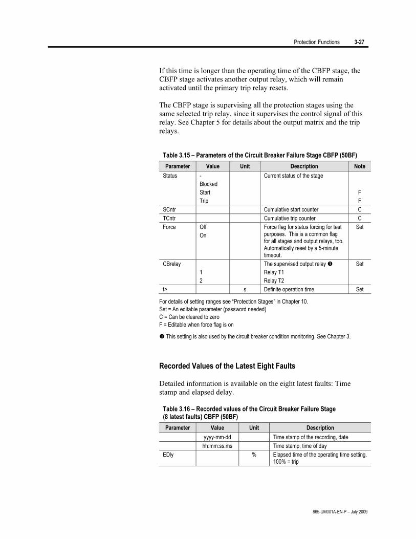
Protection Functions 3-27
865-UM001A-EN-P – July 2009
If this time is longer than the operating time of the CBFP stage, the
CBFP stage activates another output relay, which will remain
activated until the primary trip relay resets.
The CBFP stage is supervising all the protection stages using the
same selected trip relay, since it supervises the control signal of this
relay. See Chapter 5 for details about the output matrix and the trip
relays.
Table 3.15 – Parameters of the Circuit Breaker Failure Stage CBFP (50BF)
Parameter Value Unit Description Note
Status -
Blocked
Start
Trip
Current status of the stage
F
F
SCntr Cumulative start counter C
TCntr Cumulative trip counter C
Force Off
On
Force flag for status forcing for test purposes. This is a common flag for all stages and output relays, too. Automatically reset by a 5-minute timeout.
Set
CBrelay
1
2
The supervised output relay
Relay T1
Relay T2
Set
t> s Definite operation time. Set
For details of setting ranges see “Protection Stages” in Chapter 10.
Set = An editable parameter (password needed)
C = Can be cleared to zero
F = Editable when force flag is on
This setting is also used by the circuit breaker condition monitoring. See Chapter 3.
Recorded Values of the Latest Eight Faults
Detailed information is available on the eight latest faults: Time
stamp and elapsed delay.
Table 3.16 – Recorded values of the Circuit Breaker Failure Stage (8 latest faults) CBFP (50BF)
Parameter Value Unit Description
yyyy-mm-dd Time stamp of the recording, date
hh:mm:ss.ms Time stamp, time of day
EDly % Elapsed time of the operating time setting. 100% = trip
3-28 Protection Functions
865-UM001A-EN-P – July 2009
NOTE: This protection function needs optional hardware in slot X6.
More details of the hardware can be found under “Optional Two-
Channel Arc Protection Card” in Chapter 9, and “Arc Protection
Interface (Option)” in Chapter 10.
Arc protection is used for fast arc protection. The function is based
on simultaneous light and current measurement. Special arc sensors
are used to measure the light of an arc.
Three Stages for Arc Faults
There are three separate stages for the various current inputs:
• ArcI> for phase-to-phase arc faults. Current inputs
IL1, IL2, IL3 are used.
• ArcI’> for phase-to-phase arc faults. Current inputs
I’L1, I’L2, I’L3 are used.
• ArcI01> for phase-to-earth arc faults. Current input
I01 is used.
• ArcI02> for phase-to-earth arc faults. Current input
I02 is used.
Light Channel Selection
The light information source to the stages can be selected from the
following list.
• – No sensor selected. The stage will not work.
• S1 Light sensor S1.
• S2 Light sensor S2.
• S1/S2 Either one of the light sensors S1 or S2.
• BI Binary input of the arc card. 48 Vdc.
• S1/BI Light sensor S1 or the binary input.
• S2/BI Light sensor S2 or the binary input.
• S1/S2/BI Light sensor S1 or S2 or the binary input.
Binary Input
The binary input (BI) on the arc option card (see Chapter 8) can be
used to get the light indication from another relay to build selective
arc protection systems. The BI signal can also be connected to any
of the output relays, BO, indicators etc. offered by the output matrix
(See Chapter 5). BI is a dry input for 48 Vdc signal from binary
outputs of other Allen-Bradley relays or dedicated arc protection
devices by Allen-Bradley.
Arc fault protection (50ARC/50NARC) (optional)
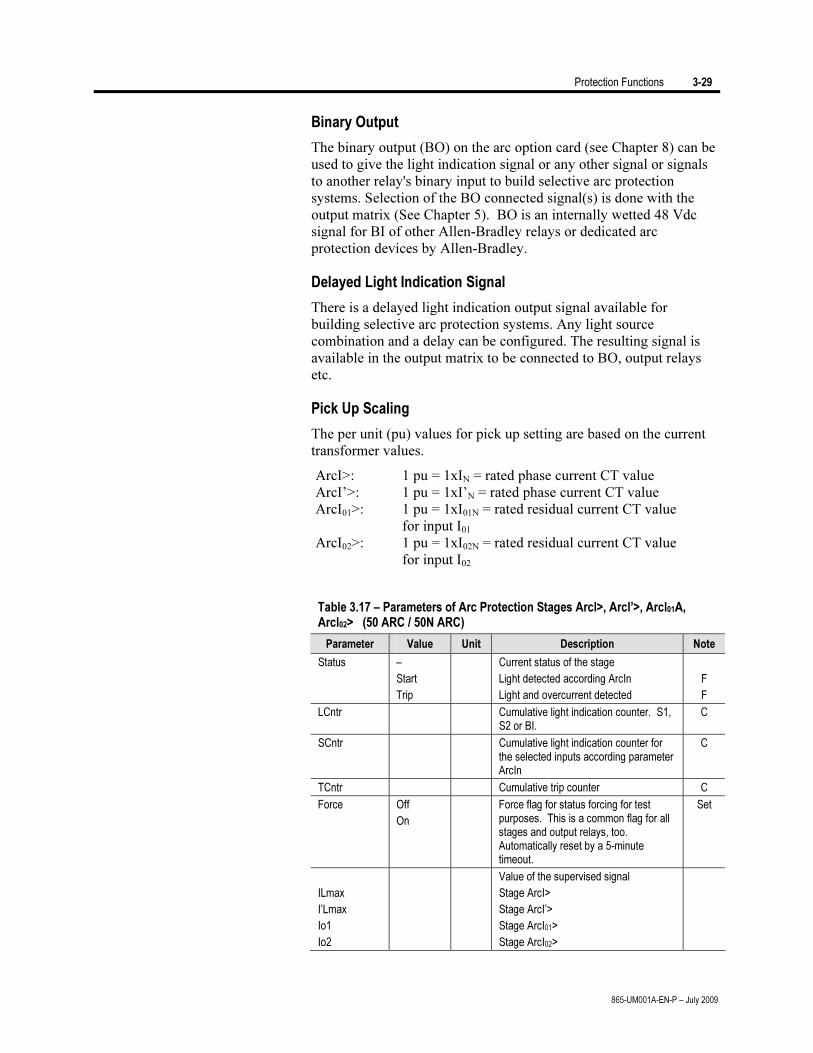
Protection Functions 3-29
865-UM001A-EN-P – July 2009
Binary Output
The binary output (BO) on the arc option card (see Chapter 8) can be
used to give the light indication signal or any other signal or signals
to another relay's binary input to build selective arc protection
systems. Selection of the BO connected signal(s) is done with the
output matrix (See Chapter 5). BO is an internally wetted 48 Vdc
signal for BI of other Allen-Bradley relays or dedicated arc
protection devices by Allen-Bradley.
Delayed Light Indication Signal
There is a delayed light indication output signal available for
building selective arc protection systems. Any light source
combination and a delay can be configured. The resulting signal is
available in the output matrix to be connected to BO, output relays
etc.
Pick Up Scaling
The per unit (pu) values for pick up setting are based on the current
transformer values.
ArcI>: 1 pu = 1xIN = rated phase current CT value
ArcI’>: 1 pu = 1xI’N = rated phase current CT value
ArcI01>: 1 pu = 1xI01N = rated residual current CT value
for input I01
ArcI02>: 1 pu = 1xI02N = rated residual current CT value
for input I02
Table 3.17 – Parameters of Arc Protection Stages Arcl>, Arcl’>, Arcl01A, Arcl02> (50 ARC / 50N ARC)
Parameter Value Unit Description Note
Status –
Start
Trip
Current status of the stage
Light detected according ArcIn
Light and overcurrent detected
F
F
LCntr Cumulative light indication counter. S1, S2 or BI.
C
SCntr Cumulative light indication counter for the selected inputs according parameter ArcIn
C
TCntr Cumulative trip counter C
Force Off
On
Force flag for status forcing for test purposes. This is a common flag for all stages and output relays, too. Automatically reset by a 5-minute timeout.
Set
ILmax
I’Lmax
Io1
Io2
Value of the supervised signal
Stage ArcI>
Stage ArcI’>
Stage ArcI01>
Stage ArcI02>
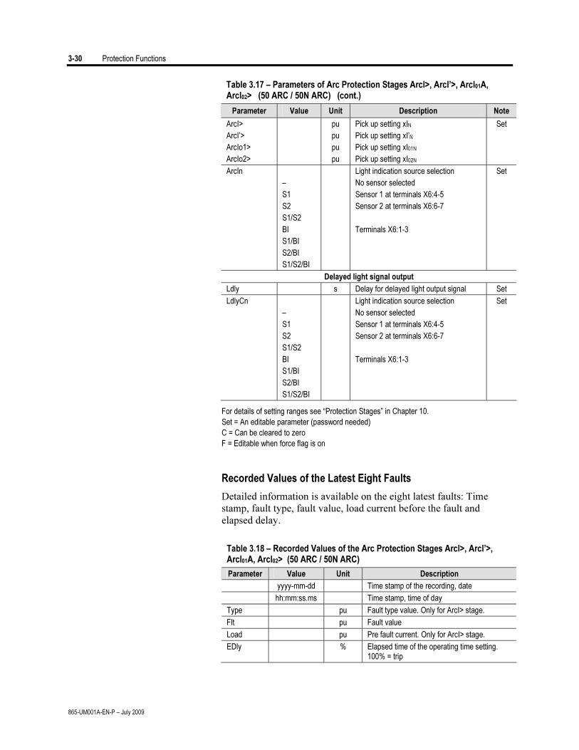
3-30 Protection Functions
865-UM001A-EN-P – July 2009
Table 3.17 – Parameters of Arc Protection Stages Arcl>, Arcl’>, Arcl01A, Arcl02> (50 ARC / 50N ARC) (cont.)
Parameter Value Unit Description Note
ArcI>
ArcI’>
ArcIo1>
ArcIo2>
pu
pu
pu
pu
Pick up setting xIN
Pick up setting xI’N
Pick up setting xI01N
Pick up setting xI02N
Set
ArcIn
–
S1
S2
S1/S2
BI
S1/BI
S2/BI
S1/S2/BI
Light indication source selection
No sensor selected
Sensor 1 at terminals X6:4-5
Sensor 2 at terminals X6:6-7
Terminals X6:1-3
Set
Delayed light signal output
Ldly s Delay for delayed light output signal Set
LdlyCn
–
S1
S2
S1/S2
BI
S1/BI
S2/BI
S1/S2/BI
Light indication source selection
No sensor selected
Sensor 1 at terminals X6:4-5
Sensor 2 at terminals X6:6-7
Terminals X6:1-3
Set
For details of setting ranges see “Protection Stages” in Chapter 10.
Set = An editable parameter (password needed)
C = Can be cleared to zero
F = Editable when force flag is on
Recorded Values of the Latest Eight Faults
Detailed information is available on the eight latest faults: Time
stamp, fault type, fault value, load current before the fault and
elapsed delay.
Table 3.18 – Recorded Values of the Arc Protection Stages Arcl>, Arcl’>, Arcl01A, Arcl02> (50 ARC / 50N ARC)
Parameter Value Unit Description
yyyy-mm-dd Time stamp of the recording, date
hh:mm:ss.ms Time stamp, time of day
Type pu Fault type value. Only for ArcI> stage.
Flt pu Fault value
Load pu Pre fault current. Only for ArcI> stage.
EDly % Elapsed time of the operating time setting. 100% = trip
Protection Functions 3-31
865-UM001A-EN-P – July 2009
Programmable Stages (99) For special applications the user can built his own protection stages
by selecting the supervised signal and the comparison mode.
The following parameters are available:
Priority •
If operation times less than 60 milliseconds are needed
select 10 ms. For operation times under one second 20 ms
is recommended. For longer operation times and THD
signals 100 ms is recommended.
Link •
The name of the supervised signal (see table below).
Cmp •
Compare mode. ‘>’ for over or ‘<’ for under comparison.
Pick-up •
Limit of the stage. The available setting range and the unit
depend on the selected signal.
t •
Definite time operation delay
Hyster •
Dead band (hysteresis)
NoCmp •
Only used with compare mode under (‘<’). This is the limit to
start the comparison. Signal values under NoCmp are not
regarded as fault.
Available Signals to be Supervised by the Programmable Stages
Alarm stages link signals Task interval
IL1 – IL3, IL1W-IL3W, I’L1W-I’L3W, IL, I’L 100ms
Io, Io2, Iocalc, I’oCalc, I1, I2, I2/I1, I2/In, I’1,
I’2, I’2/I’1, I’2/In, dIL1, dIL2, dIL3
THDIL1, THDIL2, THDIL3
Eight Independent Stages
The relay has eight independent programmable stages. Each
programmable stage can be enabled or disabled to fit the intended
application.
Setting Groups
There are two settings groups available. Switching between setting
groups can be controlled by digital inputs, virtual inputs (mimic
display, communication, logic) and manually.
There are two identical stages available with independent setting
parameters.
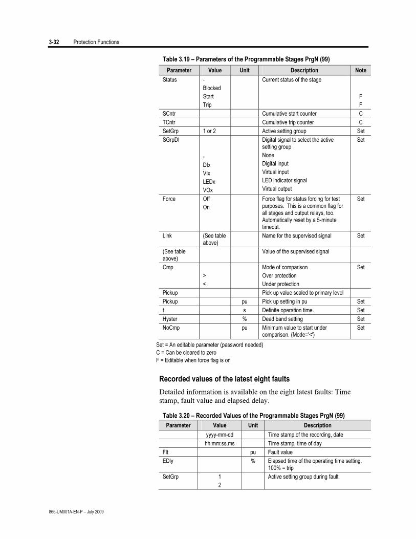
3-32 Protection Functions
865-UM001A-EN-P – July 2009
Table 3.19 – Parameters of the Programmable Stages PrgN (99)
Parameter Value Unit Description Note
Status -
Blocked
Start
Trip
Current status of the stage
F
F
SCntr Cumulative start counter C
TCntr Cumulative trip counter C
SetGrp 1 or 2 Active setting group Set
SGrpDI
-
DIx
VIx
LEDx
VOx
Digital signal to select the active setting group
None
Digital input
Virtual input
LED indicator signal
Virtual output
Set
Force Off
On
Force flag for status forcing for test purposes. This is a common flag for all stages and output relays, too. Automatically reset by a 5-minute timeout.
Set
Link (See table above)
Name for the supervised signal Set
(See table above)
Value of the supervised signal
Cmp
>
<
Mode of comparison
Over protection
Under protection
Set
Pickup Pick up value scaled to primary level
Pickup pu Pick up setting in pu Set
t s Definite operation time. Set
Hyster % Dead band setting Set
NoCmp pu Minimum value to start under comparison. (Mode='<')
Set
Set = An editable parameter (password needed)
C = Can be cleared to zero
F = Editable when force flag is on
Recorded values of the latest eight faults
Detailed information is available on the eight latest faults: Time
stamp, fault value and elapsed delay.
Table 3.20 – Recorded Values of the Programmable Stages PrgN (99)
Parameter Value Unit Description
yyyy-mm-dd Time stamp of the recording, date
hh:mm:ss.ms Time stamp, time of day
Flt pu Fault value
EDly % Elapsed time of the operating time setting. 100% = trip
SetGrp 1
2
Active setting group during fault
Protection Functions 3-33
865-UM001A-EN-P – July 2009
Inverse Time Operation The inverse time operation – i.e. inverse delay minimum time (IDMT)
type of operation – is available for several protection functions. The
common principle, formula and graphic representations of the
available inverse delay types are described in this chapter.
Inverse delay means that the operation time depends on the measured
real time process values during a fault. When utilizing an overcurrent
stage using an inverse delay, a large fault current results in faster
operation. The alternative to inverse delay is definite delay. With
definite delay a preset time is used and the operation time does not
depend on the size of a fault.
Stage Specific Inverse Delay
Some protection functions have their own specific type of inverse
delay. Details of these dedicated inverse delays are described with
the appropriate protection function.
Operation Modes
There are three operation modes to use the inverse time
characteristics:
Standard delays
Using standard delay characteristics by selecting a curve family
(IEC, IEEE, IEEE2, RI) and a delay type (Normal inverse, Very
inverse etc). See “Standard Inverse Delays IEC, IEEE, IEEE2,
RI”.
Standard delay formula with parameters
Selecting a curve family (IEC, IEEE, IEEE2) and defining one's
own parameters for the selected delay formula. This mode is
activated by setting delay type to ‘Parameters’, and then editing
the delay function parameters A ... E. See “Parameter setting
using IEC, IEEE and IEEE2 Equations”.
Fully programmable inverse delay characteristics
Building the characteristics by setting 16 [current, time] points.
The relay interpolates the values between given points with 2nd
degree polynomials. This mode is activated by setting curve
family to ‘PrgN’'. There are maximum three different
programmable curves available at the same time. Each
programmed curve can be used by any number of protection
stages. See “Programmable Inverse Time Curves”.
Local Panel Graph
The relay will show a graph of the currently used inverse delay on
the local panel display. Up and down keys can be used for zooming.
Also the delays at 20xISET, 4xISET and 2xISET are shown.
3-34 Protection Functions
865-UM001A-EN-P – July 2009
Inverse Time Setting Error Signal
If there are any errors in the inverse delay configuration the
appropriate protection stage will use definite time delay.
There is a signal ‘Setting Error’ available in output matrix, which
indicates three different situations:
1. Settings are currently changed with SetPointPS or local panel,
and there is temporarily an illegal combination of
curve/delay/points. For example if previous settings were
IEC/NI and then curve family is changed to IEEE, the setting
error will active, because there is no NI type available for IEEE
curves. After changing valid delay type for IEEE mode (for
example MI), the ‘Setting Error’ signal will release.
There are errors in formula parameters A…E, and the device
is not able to build the delay curve
There are errors in the programmable curve configuration
and the device is not able to interpolate values between the
given points.
Limitation
The maximum measured phase current is 50xIN and the maximum
directly measured earth fault current is 5xI0N. This limits the scope of
inverse curves when the setting is more than 2.5xIN (overcurrent
stages and earth fault stages using I0Calc input) or 0.25xI01N (earth
fault stages using I01 input or I02 input). The IN and I01N and I02N
depend on the order code (See Chapter 12). The table below gives the
limit values in secondary amperes.
Example of limitation:
CT = 750/5
IN = 577 A
CT0 = 100/1 (a cable CT for I0)
Secondary scaled IGNsec is now 3.85A
For overcurrent stage I> the table below gives 12.5 A. Thus the
maximum setting for I> stage giving full inverse delay range is 12.5
A / 3.85 A = 3.25 xIGN.
For earth fault stage I0> and input I01 the table below gives 0.25 A.
Thus the maximum setting for I0> stage giving full inverse delay
range is 0.25A / 1 A = 0.25 pu. This equals a 25A primary earth fault
current.
When using input signal I0Calc the corresponding setting is 12.5A / 1 A
= 12.5 pu. This equals a 9375A of primary earth fault current.
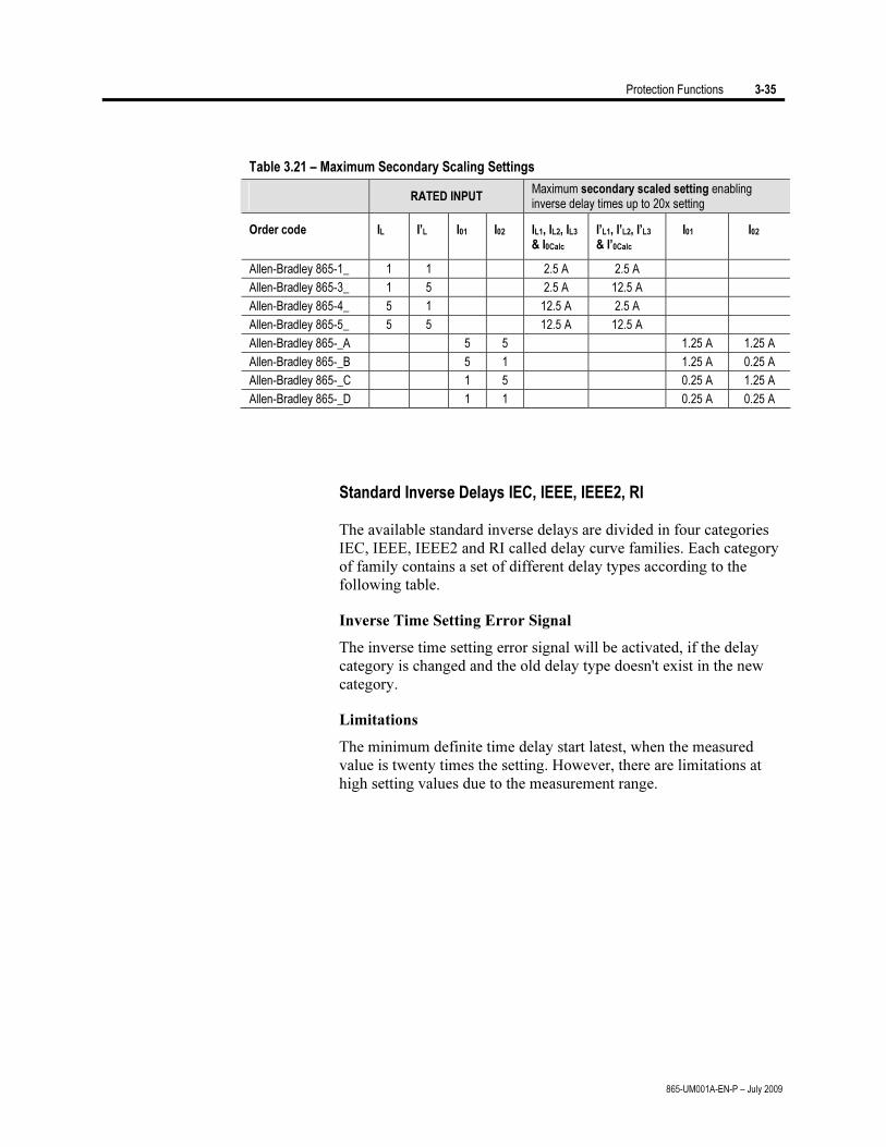
Protection Functions 3-35
865-UM001A-EN-P – July 2009
Table 3.21 – Maximum Secondary Scaling Settings
RATED INPUT Maximum secondary scaled setting enabling inverse delay times up to 20x setting
Order code IL I’L I01 I02
IL1, IL2, IL3 & I0Calc
I’L1, I’L2, I’L3 & I’0Calc
I01 I02
Allen-Bradley 865-1_ 1 1 2.5 A 2.5 A
Allen-Bradley 865-3_ 1 5 2.5 A 12.5 A
Allen-Bradley 865-4_ 5 1 12.5 A 2.5 A
Allen-Bradley 865-5_ 5 5 12.5 A 12.5 A
Allen-Bradley 865-_A 5 5 1.25 A 1.25 A
Allen-Bradley 865-_B 5 1 1.25 A 0.25 A
Allen-Bradley 865-_C 1 5 0.25 A 1.25 A
Allen-Bradley 865-_D 1 1 0.25 A 0.25 A
Standard Inverse Delays IEC, IEEE, IEEE2, RI
The available standard inverse delays are divided in four categories
IEC, IEEE, IEEE2 and RI called delay curve families. Each category
of family contains a set of different delay types according to the
following table.
Inverse Time Setting Error Signal
The inverse time setting error signal will be activated, if the delay
category is changed and the old delay type doesn't exist in the new
category.
Limitations
The minimum definite time delay start latest, when the measured
value is twenty times the setting. However, there are limitations at
high setting values due to the measurement range.
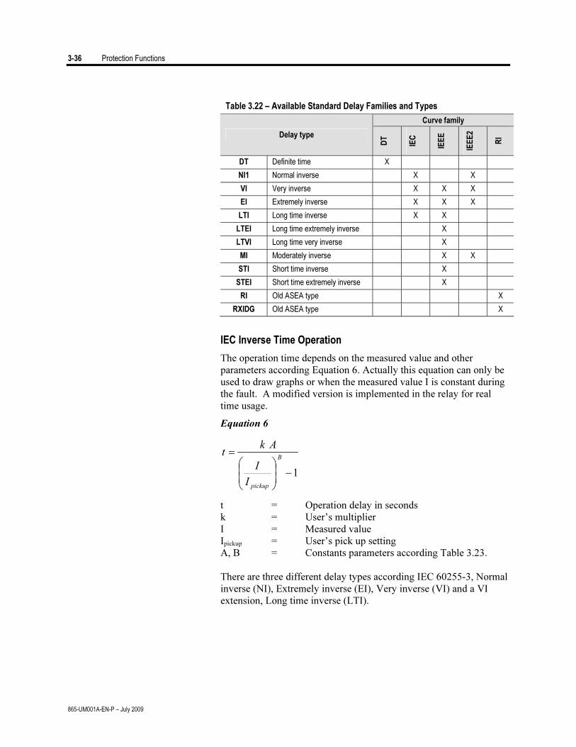
3-36 Protection Functions
865-UM001A-EN-P – July 2009
Table 3.22 – Available Standard Delay Families and Types
Curve family
Delay type
DT
IEC
IEE
E
IEE
E2
RI
DT Definite time X
NI1 Normal inverse X X
VI Very inverse X X X
EI Extremely inverse X X X
LTI Long time inverse X X
LTEI Long time extremely inverse X
LTVI Long time very inverse X
MI Moderately inverse X X
STI Short time inverse X
STEI Short time extremely inverse X
RI Old ASEA type X
RXIDG Old ASEA type X
IEC Inverse Time Operation
The operation time depends on the measured value and other
parameters according Equation 6. Actually this equation can only be
used to draw graphs or when the measured value I is constant during
the fault. A modified version is implemented in the relay for real
time usage.
Equation 6
1−⎟⎟
⎠
⎞
⎜⎜
⎝
⎛=
B
pickupI
I
Akt
t = Operation delay in seconds
k = User’s multiplier
I = Measured value
Ipickup = User’s pick up setting
A, B = Constants parameters according Table 3.23.
There are three different delay types according IEC 60255-3, Normal
inverse (NI), Extremely inverse (EI), Very inverse (VI) and a VI
extension, Long time inverse (LTI).
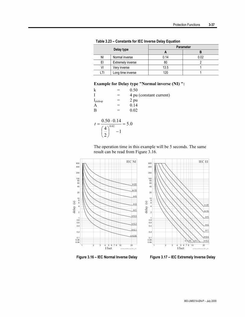
Protection Functions 3-37
865-UM001A-EN-P – July 2009
Table 3.23 – Constants for IEC Inverse Delay Equation
Parameter Delay type
A B
NI Normal inverse 0.14 0.02
EI Extremely inverse 80 2
VI Very inverse 13.5 1
LTI Long time inverse 120 1
Example for Delay type "Normal inverse (NI) ":
k = 0.50
I = 4 pu (constant current)
Ipickup = 2 pu
A = 0.14
B = 0.02
0.5
12
4
14.050.0
02.0=
−⎟⎠
⎞⎜⎝
⎛
⋅=t
The operation time in this example will be 5 seconds. The same
result can be read from Figure 3.16.
Figure 3.16 – IEC Normal Inverse Delay Figure 3.17 – IEC Extremely Inverse Delay
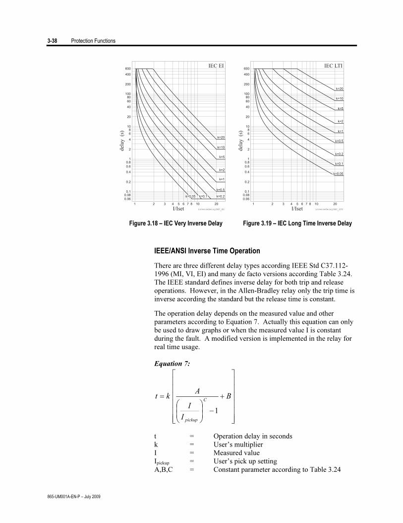
3-38 Protection Functions
865-UM001A-EN-P – July 2009
Figure 3.18 – IEC Very Inverse Delay Figure 3.19 – IEC Long Time Inverse Delay
IEEE/ANSI Inverse Time Operation
There are three different delay types according IEEE Std C37.112-
1996 (MI, VI, EI) and many de facto versions according Table 3.24.
The IEEE standard defines inverse delay for both trip and release
operations. However, in the Allen-Bradley relay only the trip time is
inverse according the standard but the release time is constant.
The operation delay depends on the measured value and other
parameters according to Equation 7. Actually this equation can only
be used to draw graphs or when the measured value I is constant
during the fault. A modified version is implemented in the relay for
real time usage.
Equation 7:
⎥⎥⎥⎥⎥⎥
⎦
⎤
⎢⎢⎢⎢⎢⎢
⎣
⎡
+
−⎟⎟
⎠
⎞
⎜⎜
⎝
⎛= B
I
I
Akt
C
pickup
1
t = Operation delay in seconds
k = User’s multiplier
I = Measured value
Ipickup = User’s pick up setting
A,B,C = Constant parameter according to Table 3.24

Protection Functions 3-39
865-UM001A-EN-P – July 2009
Table 3.24 – Constants for IEEE/ASI Inverse Delay Equation
Parameter Delay type
A B C
LTI Long time inverse 0.086 0.185 0.02
LTVI Long time very inverse 28.55 0.712 2
LTEI Long time extremely inverse 64.07 0.250 2
MI Moderately inverse 0.0515 0.1140 0.02
VI Very inverse 19.61 0.491 2
EI Extremely inverse 28.2 0.1217 2
STI Short time inverse 0.16758 0.11858 0.02
STEI Short time extremely inverse 1.281 0.005 2
Example for Delay type "Moderately inverse (MI)":
k = 0.50
I = 4 pu
Ipickup = 2 pu
A = 0.0515
B = 0.114
C = 0.02
9.11140.0
12
4
0515.050.0
02.0=
⎥⎥⎥⎥⎥
⎦
⎤
⎢⎢⎢⎢⎢
⎣
⎡
+
−⎟⎠
⎞⎜⎝
⎛⋅=t
The operation time in this example will be 1.9 seconds. The same result
can be read from Figure 3.23.
Figure 3.20 – ANSI/IEEE Long Time Figure 3.21 – ANSI/IEEE Long Time Inverse Delay Very Inverse Delay
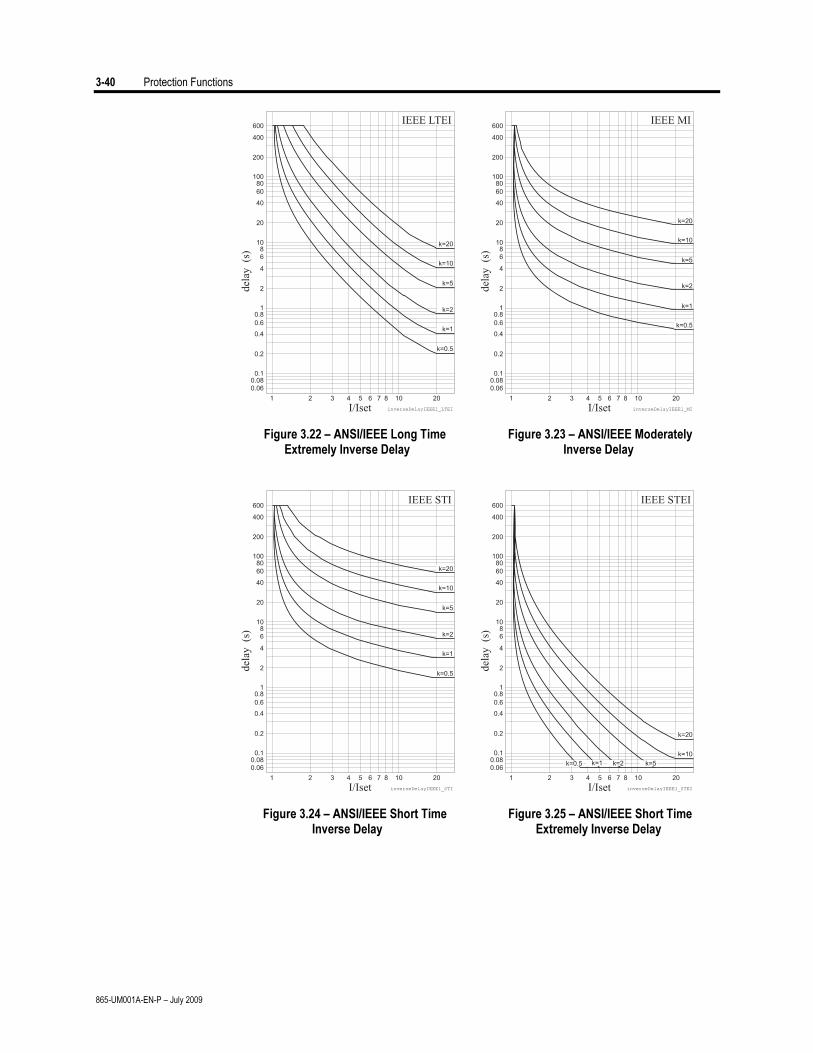
3-40 Protection Functions
865-UM001A-EN-P – July 2009
Figure 3.22 – ANSI/IEEE Long Time Figure 3.23 – ANSI/IEEE Moderately Extremely Inverse Delay Inverse Delay
Figure 3.24 – ANSI/IEEE Short Time Figure 3.25 – ANSI/IEEE Short Time Inverse Delay Extremely Inverse Delay
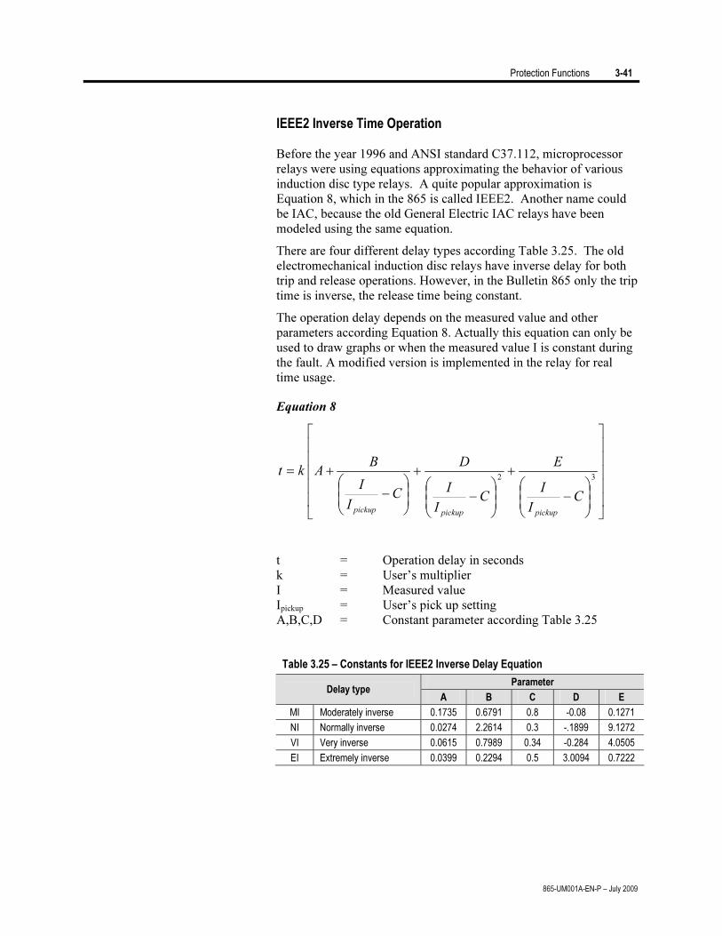
Protection Functions 3-41
865-UM001A-EN-P – July 2009
IEEE2 Inverse Time Operation
Before the year 1996 and ANSI standard C37.112, microprocessor
relays were using equations approximating the behavior of various
induction disc type relays. A quite popular approximation is
Equation 8, which in the 865 is called IEEE2. Another name could
be IAC, because the old General Electric IAC relays have been
modeled using the same equation.
There are four different delay types according Table 3.25. The old
electromechanical induction disc relays have inverse delay for both
trip and release operations. However, in the Bulletin 865 only the trip
time is inverse, the release time being constant.
The operation delay depends on the measured value and other
parameters according Equation 8. Actually this equation can only be
used to draw graphs or when the measured value I is constant during
the fault. A modified version is implemented in the relay for real
time usage.
Equation 8
⎥⎥⎥⎥⎥
⎦
⎤
⎢⎢⎢⎢⎢
⎣
⎡
⎟⎟
⎠
⎞
⎜⎜
⎝
⎛−
+
⎟⎟
⎠
⎞
⎜⎜
⎝
⎛−
+
⎟⎟
⎠
⎞
⎜⎜
⎝
⎛−
+=32
CI
I
E
CI
I
D
CI
I
BAkt
pickuppickuppickup
t = Operation delay in seconds
k = User’s multiplier
I = Measured value
Ipickup = User’s pick up setting
A,B,C,D = Constant parameter according Table 3.25
Table 3.25 – Constants for IEEE2 Inverse Delay Equation
Parameter Delay type
A B C D E
MI Moderately inverse 0.1735 0.6791 0.8 -0.08 0.1271
NI Normally inverse 0.0274 2.2614 0.3 -.1899 9.1272
VI Very inverse 0.0615 0.7989 0.34 -0.284 4.0505
EI Extremely inverse 0.0399 0.2294 0.5 3.0094 0.7222
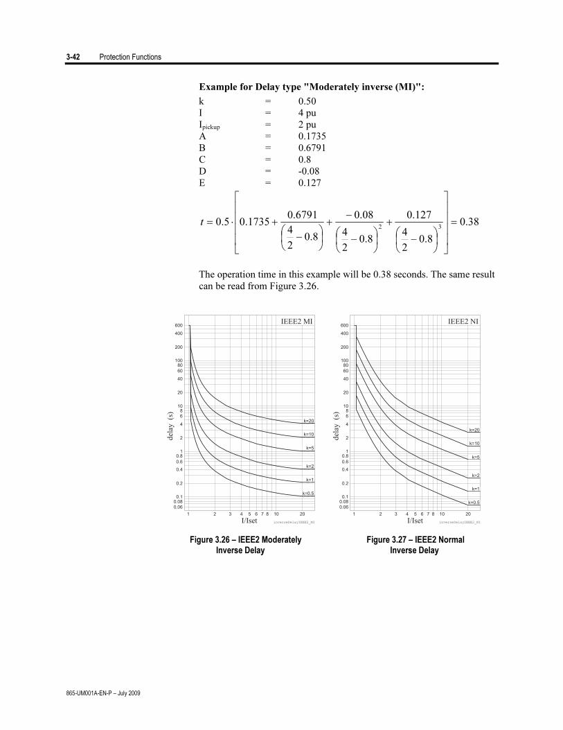
3-42 Protection Functions
865-UM001A-EN-P – July 2009
Example for Delay type "Moderately inverse (MI)":
k = 0.50
I = 4 pu
Ipickup = 2 pu
A = 0.1735
B = 0.6791
C = 0.8
D = -0.08
E = 0.127
38.0
8.02
4
127.0
8.02
4
08.0
8.02
4
6791.01735.05.0
32=
⎥⎥⎥⎥
⎦
⎤
⎢⎢⎢⎢
⎣
⎡
⎟⎠
⎞⎜⎝
⎛−
+
⎟⎠
⎞⎜⎝
⎛−
−+
⎟⎠
⎞⎜⎝
⎛−
+⋅=t
The operation time in this example will be 0.38 seconds. The same result
can be read from Figure 3.26.
Figure 3.26 – IEEE2 Moderately Figure 3.27 – IEEE2 Normal Inverse Delay Inverse Delay
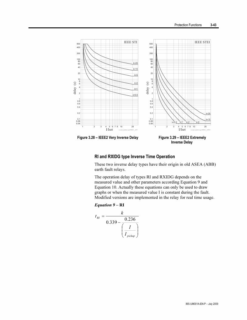
Protection Functions 3-43
865-UM001A-EN-P – July 2009
Figure 3.28 – IEEE2 Very Inverse Delay Figure 3.29 – IEEE2 Extremely Inverse Delay
RI and RXIDG type Inverse Time Operation
These two inverse delay types have their origin in old ASEA (ABB)
earth fault relays.
The operation delay of types RI and RXIDG depends on the
measured value and other parameters according Equation 9 and
Equation 10. Actually these equations can only be used to draw
graphs or when the measured value I is constant during the fault.
Modified versions are implemented in the relay for real time usage.
Equation 9 – RI
⎟⎟
⎠
⎞
⎜⎜
⎝
⎛−
=
pickup
RI
I
I
kt
236.0339.0

3-44 Protection Functions
865-UM001A-EN-P – July 2009
Equation 10 – RXIDG
pickup
RXIDGIk
It ln35.18.5 −=
t = Operation delay in seconds
k = User’s multiplier
I = Measured value
Ipickup = User’s pick up setting
Example for Delay type RI :
k = 0.50
I = 4 pu
Ipickup = 2 pu
3.2
2
4
236.0339.0
5.0=
⎟⎠
⎞⎜⎝
⎛−
=RIt
The operation time in this example will be 2.3 seconds. The same result
can be read from Figure 3.30.
Example for Delay type RXIDG:
k = 0.50
I = 4 pu
Ipickup = 2 pu
9.325.0
4ln35.18.5 =
⋅
−=RXIDGt
The operation time in this example will be 3.9 seconds. The same result
can be read from Figure 3.31.
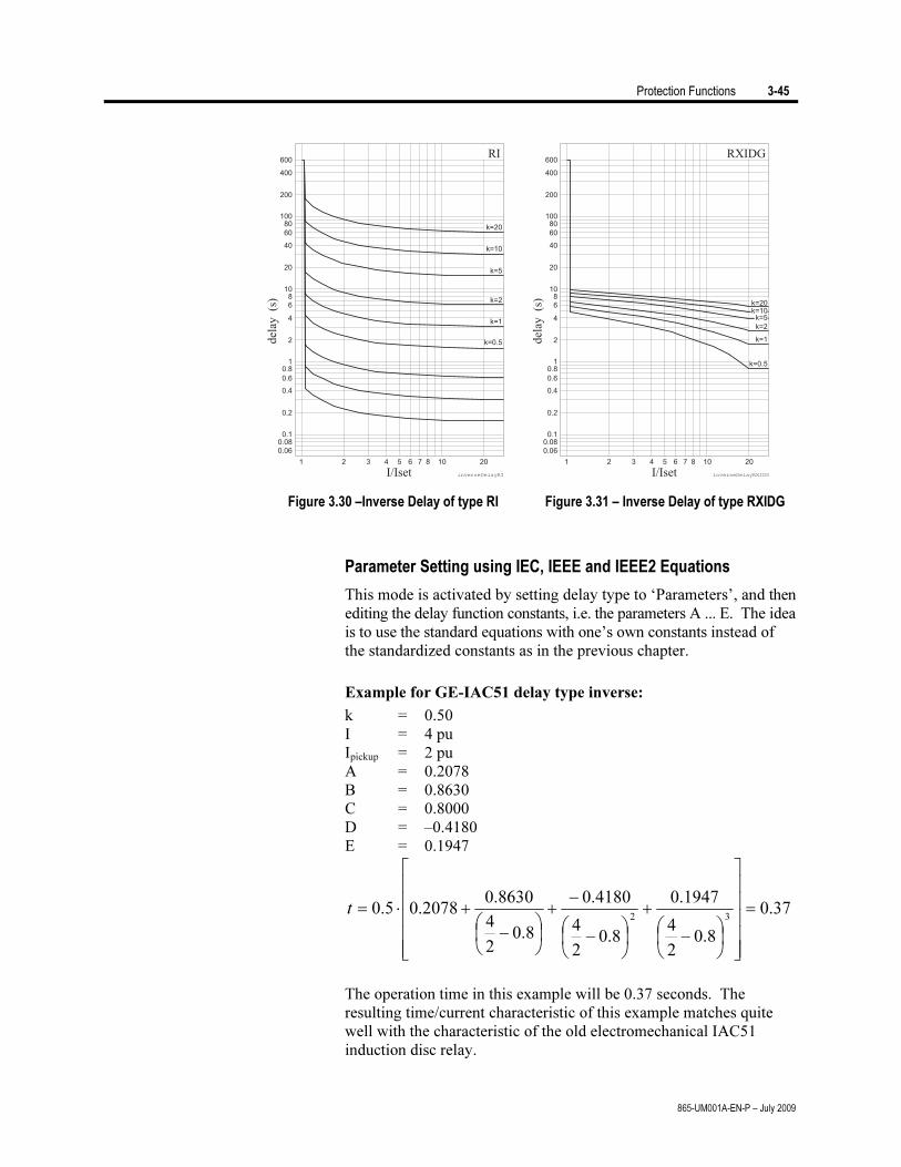
Protection Functions 3-45
865-UM001A-EN-P – July 2009
Figure 3.30 –Inverse Delay of type RI Figure 3.31 – Inverse Delay of type RXIDG
Parameter Setting using IEC, IEEE and IEEE2 Equations
This mode is activated by setting delay type to ‘Parameters’, and then
editing the delay function constants, i.e. the parameters A ... E. The idea
is to use the standard equations with one’s own constants instead of
the standardized constants as in the previous chapter.
Example for GE-IAC51 delay type inverse:
k = 0.50
I = 4 pu
Ipickup = 2 pu
A = 0.2078
B = 0.8630
C = 0.8000
D = –0.4180
E = 0.1947
37.0
8.02
4
1947.0
8.02
4
4180.0
8.02
4
8630.02078.05.0
32=
⎥⎥⎥⎥⎥
⎦
⎤
⎢⎢⎢⎢⎢
⎣
⎡
⎟⎠
⎞⎜⎝
⎛−
+
⎟⎠
⎞⎜⎝
⎛−
−+
⎟⎠
⎞⎜⎝
⎛−
+⋅=t
The operation time in this example will be 0.37 seconds. The
resulting time/current characteristic of this example matches quite
well with the characteristic of the old electromechanical IAC51
induction disc relay.
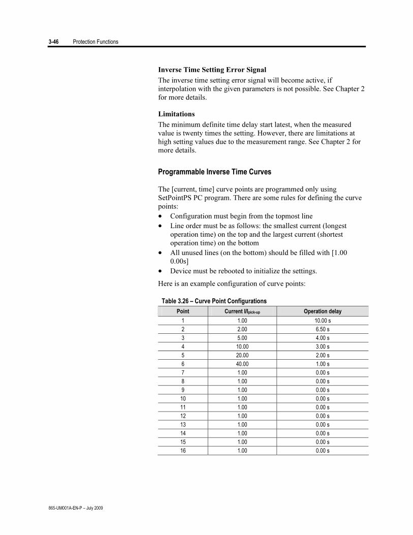
3-46 Protection Functions
865-UM001A-EN-P – July 2009
Inverse Time Setting Error Signal
The inverse time setting error signal will become active, if
interpolation with the given parameters is not possible. See Chapter 2
for more details.
Limitations
The minimum definite time delay start latest, when the measured
value is twenty times the setting. However, there are limitations at
high setting values due to the measurement range. See Chapter 2 for
more details.
Programmable Inverse Time Curves
The [current, time] curve points are programmed only using
SetPointPS PC program. There are some rules for defining the curve
points:
• Configuration must begin from the topmost line
• Line order must be as follows: the smallest current (longest
operation time) on the top and the largest current (shortest
operation time) on the bottom
• All unused lines (on the bottom) should be filled with [1.00
0.00s]
• Device must be rebooted to initialize the settings.
Here is an example configuration of curve points:
Table 3.26 – Curve Point Configurations
Point Current I/Ipick-up Operation delay
1 1.00 10.00 s
2 2.00 6.50 s
3 5.00 4.00 s
4 10.00 3.00 s
5 20.00 2.00 s
6 40.00 1.00 s
7 1.00 0.00 s
8 1.00 0.00 s
9 1.00 0.00 s
10 1.00 0.00 s
11 1.00 0.00 s
12 1.00 0.00 s
13 1.00 0.00 s
14 1.00 0.00 s
15 1.00 0.00 s
16 1.00 0.00 s
Protection Functions 3-47
865-UM001A-EN-P – July 2009
Inverse Time Setting Error Signal
The inverse time setting error signal will be activated, if interpolation
with the given points fails. See section “Inverse Time Operation” for
more details.
Limitations
The minimum definite time delay start latest, when the measured
value is twenty times the setting. However, there are limitations at
high setting values due to the measurement range. See section
“Inverse Time Operation” in Chapter 2 for more details.

3-48 Protection Functions
865-UM001A-EN-P – July 2009
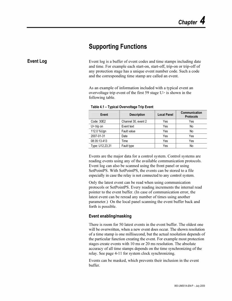
Chapter 4
865-UM001A-EN-P – July 2009
Supporting Functions
Event Log Event log is a buffer of event codes and time stamps including date and time. For example each start-on, start-off, trip-on or trip-off of any protection stage has a unique event number code. Such a code and the corresponding time stamp are called an event.
As an example of information included with a typical event an overvoltage trip event of the first 59 stage U> is shown in the following table.
Table 4.1 – Typical Overvoltage Trip Event
Event Description Local Panel Communication
Protocols
Code: 30E2 Channel 30, event 2 Yes Yes
U> trip on Event text Yes No
112.0 %Ugn Fault value Yes No
2007-01-31 Date Yes Yes
08:35:13.413 Time Yes Yes
Type: U12,23,31 Fault type Yes No
Events are the major data for a control system. Control systems are reading events using any of the available communication protocols. Event log can also be scanned using the front panel or using SetPointPS. With SetPointPS, the events can be stored to a file especially in case the relay is not connected to any control system.
Only the latest event can be read when using communication protocols or SetPointPS. Every reading increments the internal read pointer to the event buffer. (In case of communication error, the latest event can be reread any number of times using another parameter.) On the local panel scanning the event buffer back and forth is possible.
Event enabling/masking
There is room for 50 latest events in the event buffer. The oldest one will be overwritten, when a new event does occur. The shown resolution of a time stamp is one millisecond, but the actual resolution depends of the particular function creating the event. For example most protection stages create events with 10 ms or 20 ms resolution. The absolute accuracy of all time stamps depends on the time synchronizing of the relay. See page 4-11 for system clock synchronizing.
Events can be masked, which prevents their inclusion in the event buffer.
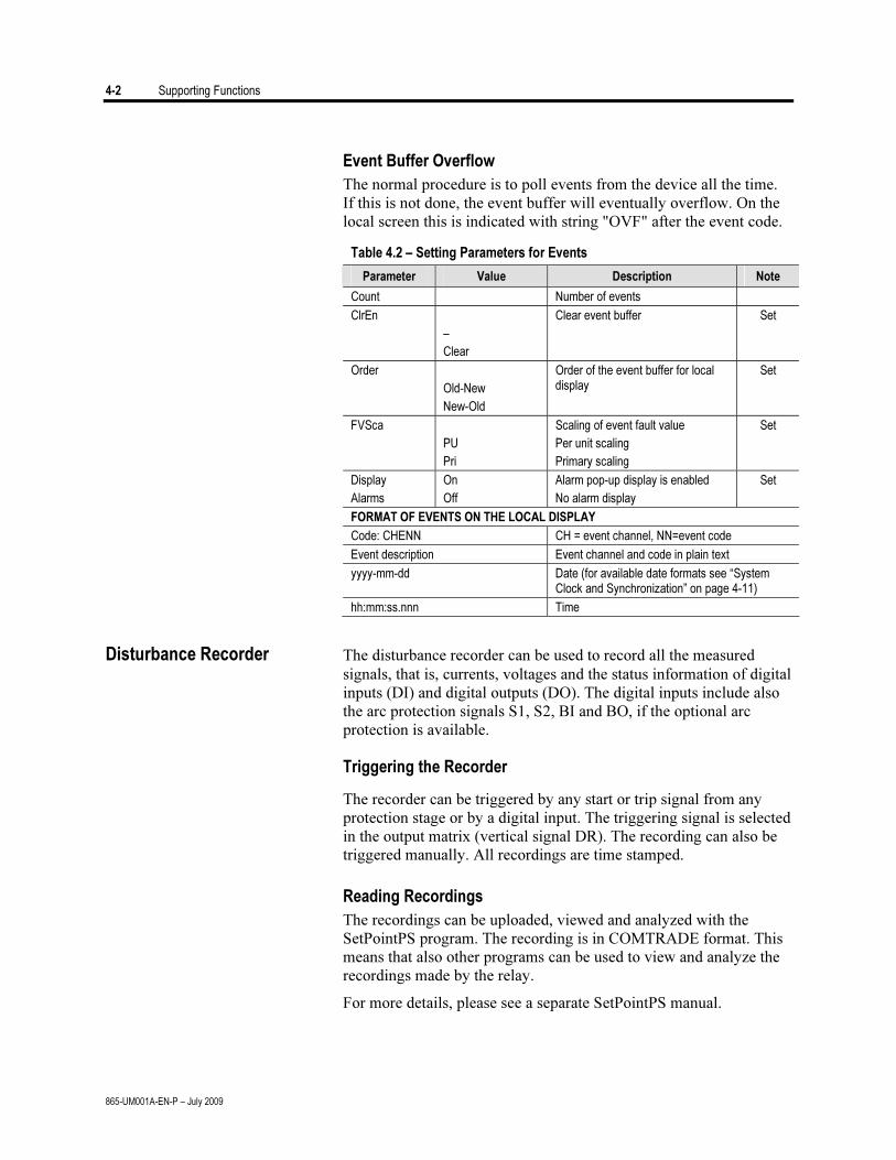
4-2 Supporting Functions
865-UM001A-EN-P – July 2009
Event Buffer Overflow
The normal procedure is to poll events from the device all the time. If this is not done, the event buffer will eventually overflow. On the local screen this is indicated with string "OVF" after the event code.
Table 4.2 – Setting Parameters for Events
Parameter Value Description Note
Count Number of events
ClrEn
–
Clear
Clear event buffer Set
Order
Old-New
New-Old
Order of the event buffer for local display
Set
FVSca
PU
Pri
Scaling of event fault value
Per unit scaling
Primary scaling
Set
Display
Alarms
On
Off
Alarm pop-up display is enabled
No alarm display
Set
FORMAT OF EVENTS ON THE LOCAL DISPLAY
Code: CHENN CH = event channel, NN=event code
Event description Event channel and code in plain text
yyyy-mm-dd Date (for available date formats see “System Clock and Synchronization” on page 4-11)
hh:mm:ss.nnn Time
Disturbance Recorder The disturbance recorder can be used to record all the measured signals, that is, currents, voltages and the status information of digital inputs (DI) and digital outputs (DO). The digital inputs include also the arc protection signals S1, S2, BI and BO, if the optional arc protection is available.
Triggering the Recorder
The recorder can be triggered by any start or trip signal from any protection stage or by a digital input. The triggering signal is selected in the output matrix (vertical signal DR). The recording can also be triggered manually. All recordings are time stamped.
Reading Recordings
The recordings can be uploaded, viewed and analyzed with the SetPointPS program. The recording is in COMTRADE format. This means that also other programs can be used to view and analyze the recordings made by the relay.
For more details, please see a separate SetPointPS manual.
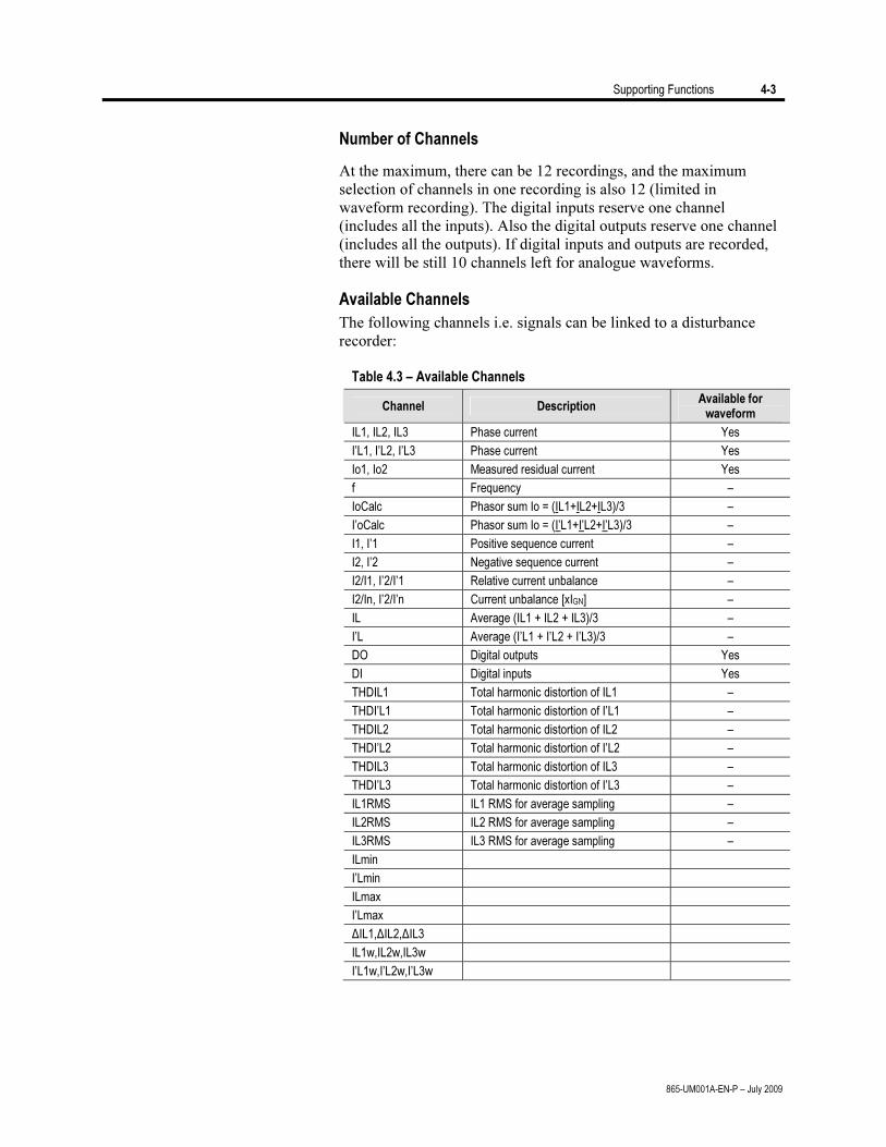
Supporting Functions 4-3
865-UM001A-EN-P – July 2009
Number of Channels
At the maximum, there can be 12 recordings, and the maximum selection of channels in one recording is also 12 (limited in waveform recording). The digital inputs reserve one channel (includes all the inputs). Also the digital outputs reserve one channel (includes all the outputs). If digital inputs and outputs are recorded, there will be still 10 channels left for analogue waveforms.
Available Channels
The following channels i.e. signals can be linked to a disturbance recorder:
Table 4.3 – Available Channels
Channel Description Available for
waveform
IL1, IL2, IL3 Phase current Yes
I’L1, I’L2, I’L3 Phase current Yes
Io1, Io2 Measured residual current Yes
f Frequency –
IoCalc Phasor sum Io = (IL1+IL2+IL3)/3 –
I’oCalc Phasor sum Io = (I’L1+I’L2+I’L3)/3 –
I1, I’1 Positive sequence current –
I2, I’2 Negative sequence current –
I2/I1, I’2/I’1 Relative current unbalance –
I2/In, I’2/I’n Current unbalance [xIGN] –
IL Average (IL1 + IL2 + IL3)/3 –
I’L Average (I’L1 + I’L2 + I’L3)/3 –
DO Digital outputs Yes
DI Digital inputs Yes
THDIL1 Total harmonic distortion of IL1 –
THDI’L1 Total harmonic distortion of I’L1 –
THDIL2 Total harmonic distortion of IL2 –
THDI’L2 Total harmonic distortion of I’L2 –
THDIL3 Total harmonic distortion of IL3 –
THDI’L3 Total harmonic distortion of I’L3 –
IL1RMS IL1 RMS for average sampling –
IL2RMS IL2 RMS for average sampling –
IL3RMS IL3 RMS for average sampling –
ILmin
I’Lmin
ILmax
I’Lmax
ΔIL1,ΔIL2,ΔIL3
IL1w,IL2w,IL3w
I’L1w,I’L2w,I’L3w
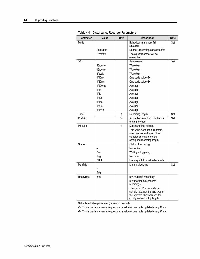
4-4 Supporting Functions
865-UM001A-EN-P – July 2009
Table 4.4 – Disturbance Recorder Parameters
Parameter Value Unit Description Note
Mode
Saturated
Overflow
Behaviour in memory full situation:
No more recordings are accepted
The oldest recorder will be overwritten
Set
SR
32/cycle
16/cycle
8/cycle
1/10ms
1/20ms
1/200ms
1/1s
1/5s
1/10s
1/15s
1/30s
1/1min
Sample rate
Waveform
Waveform
Waveform
One cycle value
One cycle value
Average
Average
Average
Average
Average
Average
Average
Set
Time s Recording length Set
PreTrig % Amount of recording data before the trig moment
Set
MaxLen s Maximum time setting.
This value depends on sample rate, number and type of the selected channels and the configured recording length.
Status
–
Run
Trig
FULL
Status of recording
Not active
Waiting a triggering
Recording
Memory is full in saturated mode
ManTrig
–
Trig
Manual triggering Set
ReadyRec n/m n = Available recordings
m = maximum number of recordings
The value of 'm' depends on sample rate, number and type of the selected channels and the configured recording length.
Set = An editable parameter (password needed)
This is the fundamental frequency rms value of one cycle updated every 10 ms.
This is the fundamental frequency rms value of one cycle updated every 20 ms.
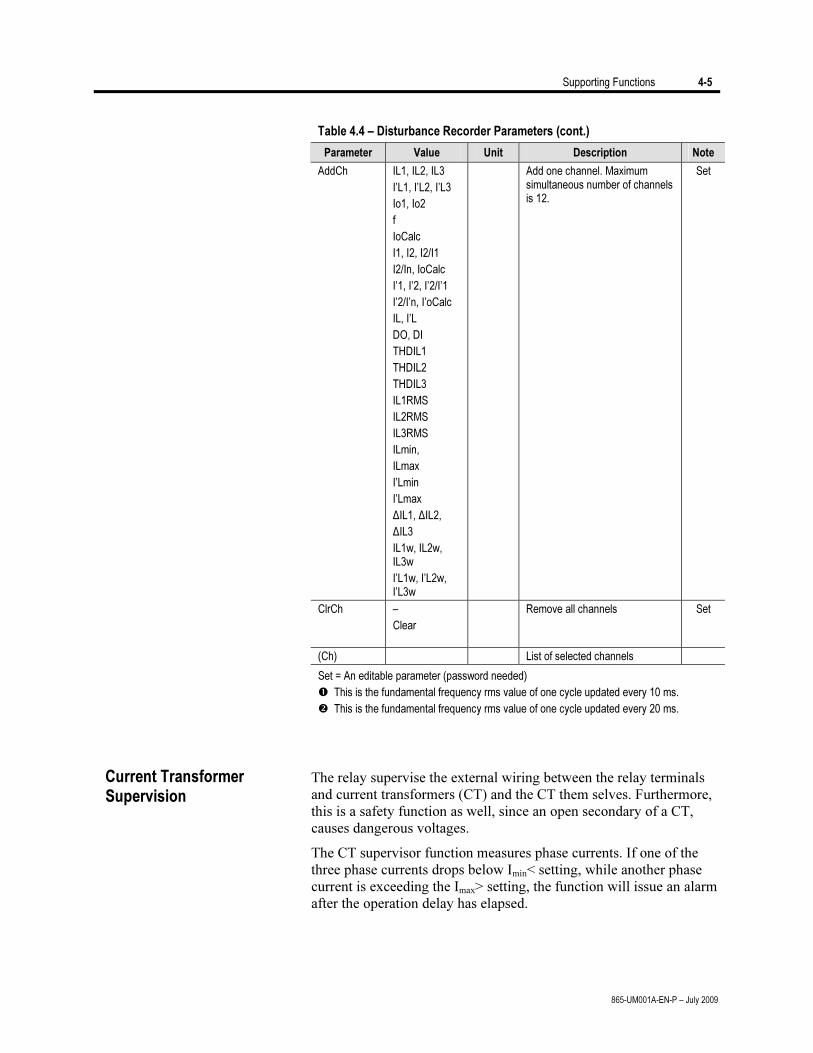
Supporting Functions 4-5
865-UM001A-EN-P – July 2009
Table 4.4 – Disturbance Recorder Parameters (cont.)
Parameter Value Unit Description Note
AddCh IL1, IL2, IL3
I’L1, I’L2, I’L3
Io1, Io2
f
IoCalc
I1, I2, I2/I1
I2/In, IoCalc
I’1, I’2, I’2/I’1
I’2/I’n, I’oCalc
IL, I’L
DO, DI
THDIL1
THDIL2
THDIL3
IL1RMS
IL2RMS
IL3RMS
ILmin,
ILmax
I’Lmin
I’Lmax
ΔIL1, ΔIL2,
ΔIL3
IL1w, IL2w, IL3w
I’L1w, I’L2w, I’L3w
Add one channel. Maximum simultaneous number of channels is 12.
Set
ClrCh –
Clear
Remove all channels Set
(Ch) List of selected channels
Set = An editable parameter (password needed)
This is the fundamental frequency rms value of one cycle updated every 10 ms.
This is the fundamental frequency rms value of one cycle updated every 20 ms.
The relay supervise the external wiring between the relay terminals
and current transformers (CT) and the CT them selves. Furthermore, this is a safety function as well, since an open secondary of a CT, causes dangerous voltages.
The CT supervisor function measures phase currents. If one of the three phase currents drops below Imin< setting, while another phase current is exceeding the Imax> setting, the function will issue an alarm after the operation delay has elapsed.
Current Transformer Supervision
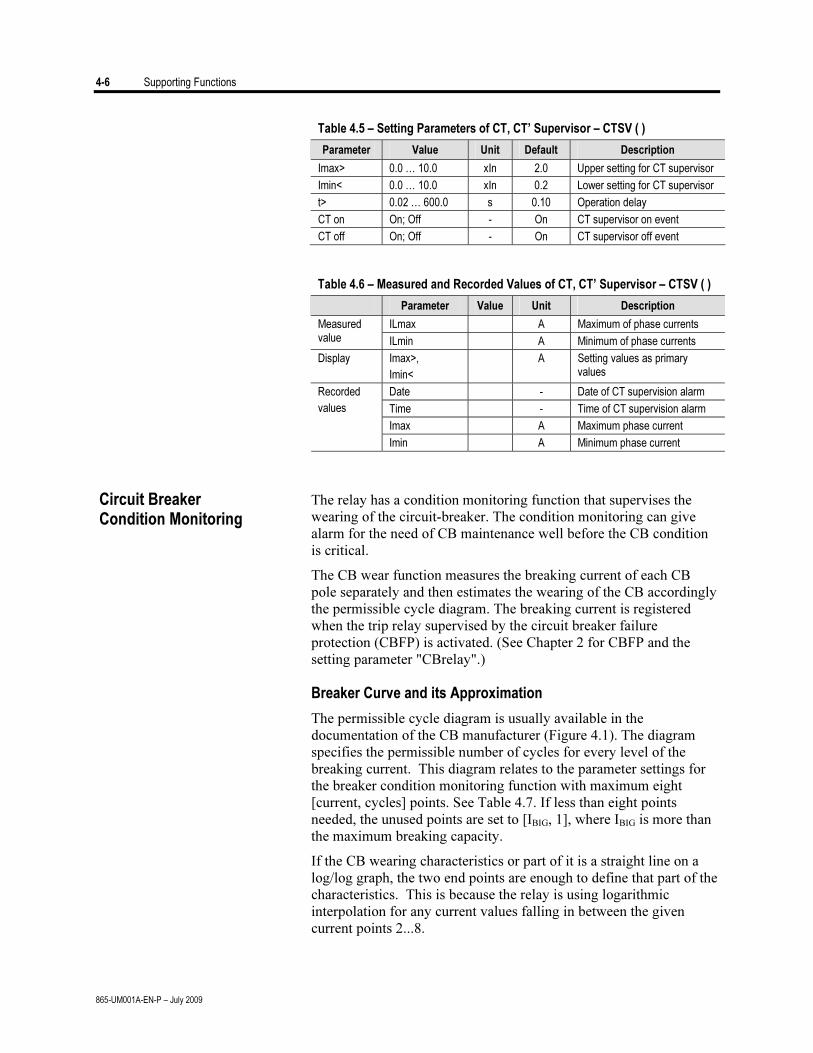
4-6 Supporting Functions
865-UM001A-EN-P – July 2009
Table 4.5 – Setting Parameters of CT, CT’ Supervisor – CTSV ( )
Parameter Value Unit Default Description
Imax> 0.0 … 10.0 xIn 2.0 Upper setting for CT supervisor
Imin< 0.0 … 10.0 xIn 0.2 Lower setting for CT supervisor
t> 0.02 … 600.0 s 0.10 Operation delay
CT on On; Off - On CT supervisor on event
CT off On; Off - On CT supervisor off event
Table 4.6 – Measured and Recorded Values of CT, CT’ Supervisor – CTSV ( )
Parameter Value Unit Description
ILmax A Maximum of phase currents Measured value ILmin A Minimum of phase currents
Display Imax>,
Imin<
A Setting values as primary values
Date - Date of CT supervision alarm
Time - Time of CT supervision alarm
Imax A Maximum phase current
Recorded
values
Imin A Minimum phase current
The relay has a condition monitoring function that supervises the wearing of the circuit-breaker. The condition monitoring can give alarm for the need of CB maintenance well before the CB condition is critical.
The CB wear function measures the breaking current of each CB pole separately and then estimates the wearing of the CB accordingly the permissible cycle diagram. The breaking current is registered when the trip relay supervised by the circuit breaker failure protection (CBFP) is activated. (See Chapter 2 for CBFP and the setting parameter "CBrelay".)
Breaker Curve and its Approximation
The permissible cycle diagram is usually available in the documentation of the CB manufacturer (Figure 4.1). The diagram specifies the permissible number of cycles for every level of the breaking current. This diagram relates to the parameter settings for the breaker condition monitoring function with maximum eight [current, cycles] points. See Table 4.7. If less than eight points needed, the unused points are set to [IBIG, 1], where IBIG is more than the maximum breaking capacity.
If the CB wearing characteristics or part of it is a straight line on a log/log graph, the two end points are enough to define that part of the characteristics. This is because the relay is using logarithmic interpolation for any current values falling in between the given current points 2...8.
Circuit Breaker Condition Monitoring
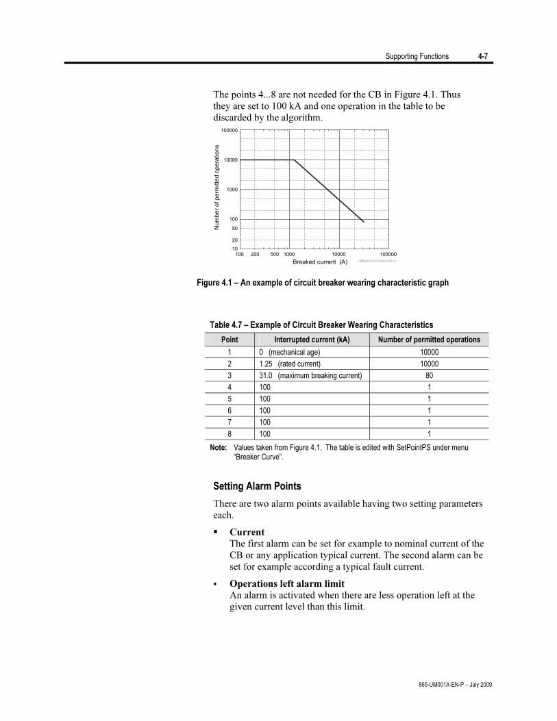
Supporting Functions 4-7
865-UM001A-EN-P – July 2009
The points 4...8 are not needed for the CB in Figure 4.1. Thus
they are set to 100 kA and one operation in the table to be discarded by the algorithm.
10
20
50
100
1000
10000
100000
100 200 500 1000 10000 100000
Nu
mb
er
of
pe
rmitte
do
pe
ratio
ns
Breaked current (A) CBWEARcharacteristics
Figure 4.1 – An example of circuit breaker wearing characteristic graph
Table 4.7 – Example of Circuit Breaker Wearing Characteristics
Point Interrupted current (kA) Number of permitted operations
1 0 (mechanical age) 10000
2 1.25 (rated current) 10000
3 31.0 (maximum breaking current) 80
4 100 1
5 100 1
6 100 1
7 100 1
8 100 1
Note: Values taken from Figure 4.1. The table is edited with SetPointPS under menu “Breaker Curve”.
Setting Alarm Points
There are two alarm points available having two setting parameters each.
Current The first alarm can be set for example to nominal current of the CB or any application typical current. The second alarm can be set for example according a typical fault current.
Operations left alarm limit An alarm is activated when there are less operation left at the given current level than this limit.
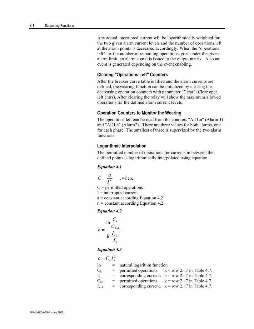
4-8 Supporting Functions
865-UM001A-EN-P – July 2009
Any actual interrupted current will be logarithmically weighted for
the two given alarm current levels and the number of operations left at the alarm points is decreased accordingly. When the "operations left" i.e. the number of remaining operations, goes under the given alarm limit, an alarm signal is issued to the output matrix. Also an event is generated depending on the event enabling.
Clearing "Operations Left" Counters
After the breaker curve table is filled and the alarm currents are defined, the wearing function can be initialized by clearing the decreasing operation counters with parameter "Clear" (Clear oper. left cntrs). After clearing the relay will show the maximum allowed operations for the defined alarm current levels.
Operation Counters to Monitor the Wearing
The operations left can be read from the counters "Al1Ln" (Alarm 1) and "Al2Ln" (Alarm2). There are three values for both alarms, one for each phase. The smallest of three is supervised by the two alarm functions.
Logarithmic Interpolation
The permitted number of operations for currents in between the defined points is logarithmically interpolated using equation
Equation 4.1
n
I
aC = , where
C = permitted operations I = interrupted current a = constant according Equation 4.2 n = constant according Equation 4.2
Equation 4.2
k
k
k
k
I
I
C
C
n
1
1
ln
ln
+
+
=
Equation 4.3
2
kkICa =
ln = natural logarithm function Ck = permitted operations. k = row 2...7 in Table 4.7. Ik = corresponding current. k = row 2...7 in Table 4.7. Ck+1 = permitted operations. k = row 2...7 in Table 4.7. Ik+1 = corresponding current. k = row 2...7 in Table 4.7.
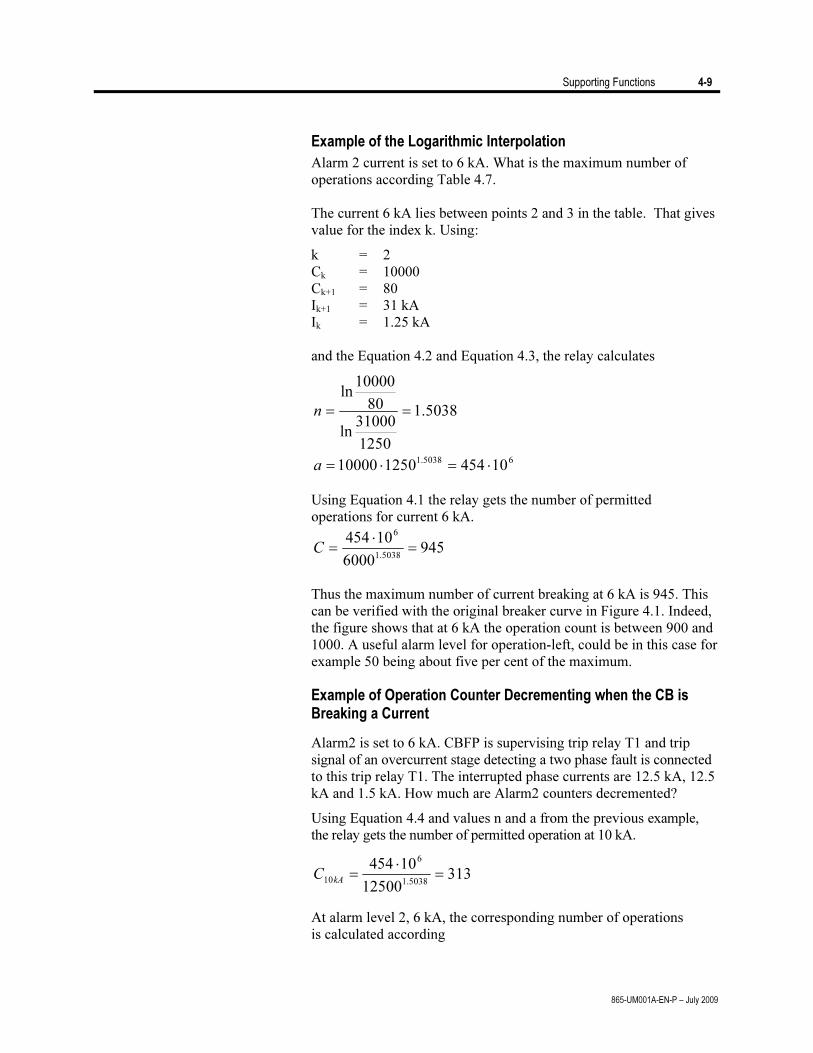
Supporting Functions 4-9
865-UM001A-EN-P – July 2009
Example of the Logarithmic Interpolation
Alarm 2 current is set to 6 kA. What is the maximum number of operations according Table 4.7.
The current 6 kA lies between points 2 and 3 in the table. That gives
value for the index k. Using:
k = 2 Ck = 10000 Ck+1 = 80 Ik+1 = 31 kA Ik = 1.25 kA and the Equation 4.2 and Equation 4.3, the relay calculates
5038.1
1250
31000ln
80
10000ln
==n
65038.110454125010000 ⋅=⋅=a
Using Equation 4.1 the relay gets the number of permitted operations for current 6 kA.
9456000
10454
5038.1
6
=
⋅
=C
Thus the maximum number of current breaking at 6 kA is 945. This
can be verified with the original breaker curve in Figure 4.1. Indeed, the figure shows that at 6 kA the operation count is between 900 and 1000. A useful alarm level for operation-left, could be in this case for example 50 being about five per cent of the maximum.
Example of Operation Counter Decrementing when the CB is Breaking a Current
Alarm2 is set to 6 kA. CBFP is supervising trip relay T1 and trip signal of an overcurrent stage detecting a two phase fault is connected to this trip relay T1. The interrupted phase currents are 12.5 kA, 12.5 kA and 1.5 kA. How much are Alarm2 counters decremented?
Using Equation 4.4 and values n and a from the previous example, the relay gets the number of permitted operation at 10 kA.
31312500
10454
5038.1
6
10=
⋅
=kA
C
At alarm level 2, 6 kA, the corresponding number of operations is calculated according
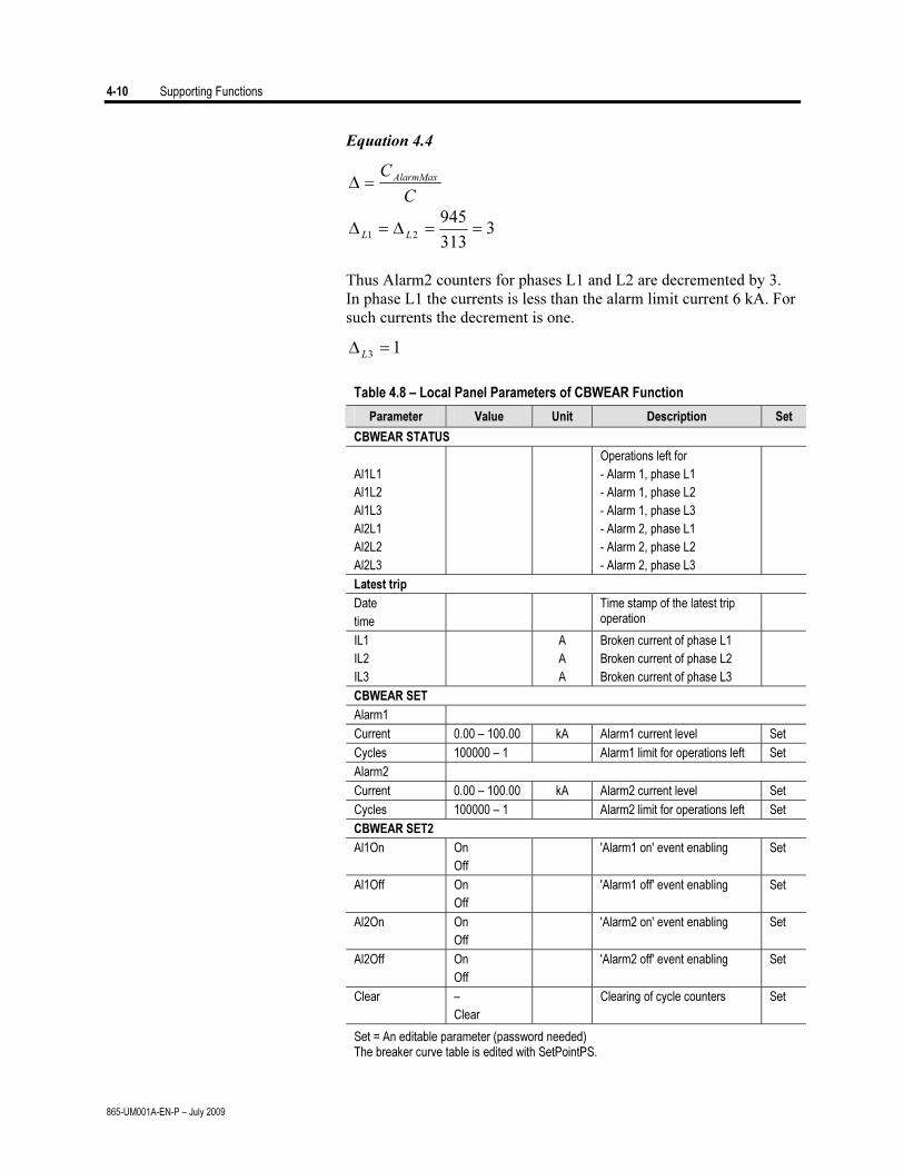
4-10 Supporting Functions
865-UM001A-EN-P – July 2009
Equation 4.4
C
CAlarmMax
=Δ
3313
945
21==Δ=Δ
LL
Thus Alarm2 counters for phases L1 and L2 are decremented by 3.
In phase L1 the currents is less than the alarm limit current 6 kA. For such currents the decrement is one.
13=Δ
L
Table 4.8 – Local Panel Parameters of CBWEAR Function
Parameter Value Unit Description Set
CBWEAR STATUS
Al1L1
Al1L2
Al1L3
Al2L1
Al2L2
Al2L3
Operations left for
- Alarm 1, phase L1
- Alarm 1, phase L2
- Alarm 1, phase L3
- Alarm 2, phase L1
- Alarm 2, phase L2
- Alarm 2, phase L3
Latest trip
Date
time
Time stamp of the latest trip operation
IL1
IL2
IL3
A
A
A
Broken current of phase L1
Broken current of phase L2
Broken current of phase L3
CBWEAR SET
Alarm1
Current 0.00 – 100.00 kA Alarm1 current level Set
Cycles 100000 – 1 Alarm1 limit for operations left Set
Alarm2
Current 0.00 – 100.00 kA Alarm2 current level Set
Cycles 100000 – 1 Alarm2 limit for operations left Set
CBWEAR SET2
Al1On On
Off
'Alarm1 on' event enabling Set
Al1Off On
Off
'Alarm1 off' event enabling Set
Al2On On
Off
'Alarm2 on' event enabling Set
Al2Off On
Off
'Alarm2 off' event enabling Set
Clear –
Clear
Clearing of cycle counters Set
Set = An editable parameter (password needed) The breaker curve table is edited with SetPointPS.
Supporting Functions 4-11
865-UM001A-EN-P – July 2009
The internal clock of the relay is used to time stamp events and disturbance recordings.
The system clock should be externally synchronized to get comparable event time stamps for all the relays in the system.
The synchronizing is based on the difference of the internal time and the synchronizing message or pulse. This deviation is filtered and the internal time is corrected softly towards a zero deviation.
Adapting Auto Adjust
During tens of hours of synchronizing the device will learn its average error and starts to make small corrections by itself. The target is that when the next synchronizing message is received, the deviation is already near zero. Parameters "AAIntv" and "AvDrft" will show the adapted correction time interval of this ±1 ms auto-adjust function.
Time Drift Correction Without External Sync
If any external synchronizing source is not available and the system clock has a known steady drift, it is possible to roughly correct the clock error by editing the parameters "AAIntv" and "AvDrft". The following equation can be used if the previous "AAIntv" value has been zero.
WeekDriftInOne
AAIntv8.604
=
If the auto-adjust interval "AAIntv" has not been zero, but further
trimming is still needed, the following equation can be used to calculate a new auto-adjust interval.
8.604
1
1
WeekDriftInOne
AAIntv
AAIntv
PREVIOUS
NEW
+
=
The term DriftInOneWeek/604.8 may be replaced with the relative drift
multiplied by 1000, if some other period than one week has been used. For example if the drift has been 37 seconds in 14 days, the relative drift is 37*1000/ (14*24*3600) = 0.0306 ms/s.
System Clock and Synchronization
4-12 Supporting Functions
865-UM001A-EN-P – July 2009
Example 1:
If there has been no external sync and the relay's clock is leading sixty-one seconds a week and the parameter AAIntv has been zero, the parameters are set as
sAAIntv
LeadAvDrft
9.961
8.604==
=
With these parameter values the system clock corrects itself with
–1 ms every 9.9 seconds which equals 61.091 s/week. Example 2:
If there is no external sync and the relay's clock has been lagging five seconds in nine days and the AAIntv has been 9.9 s, leading, then the parameters are set as
6.10
3600249
5000
9.9
1
1=
⋅⋅
−
=NEW
AAIntv
LeadAvDrft =
NOTE: When the internal time is roughly correct – deviation is less than four seconds – any synchronizing or auto-adjust will never turn the clock backwards. Instead, in case the clock is leading, it is softly slowed down to maintain causality.
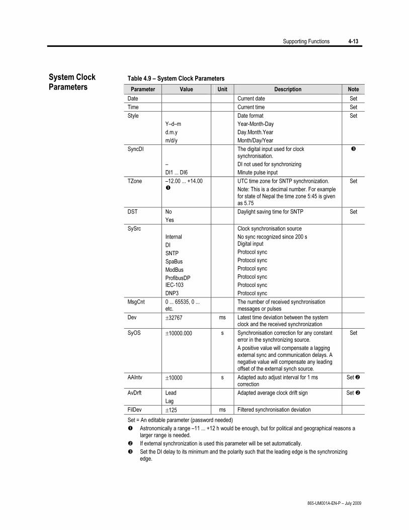
Supporting Functions 4-13
865-UM001A-EN-P – July 2009
Table 4.9 – System Clock Parameters
Parameter Value Unit Description Note
Date Current date Set
Time Current time Set
Style
Y–d–m
d.m.y
m/d/y
Date format
Year-Month-Day
Day.Month.Year
Month/Day/Year
Set
SyncDI
–
DI1 ... DI6
The digital input used for clock synchronisation.
DI not used for synchronizing
Minute pulse input
TZone –12.00 ... +14.00
UTC time zone for SNTP synchronization.
Note: This is a decimal number. For example for state of Nepal the time zone 5:45 is given as 5.75
Set
DST No
Yes
Daylight saving time for SNTP Set
SySrc
Internal
DI
SNTP
SpaBus
ModBus
ProfibusDP IEC-103
DNP3
Clock synchronisation source
No sync recognized since 200 s Digital input
Protocol sync
Protocol sync
Protocol sync
Protocol sync
Protocol sync
Protocol sync
MsgCnt 0 ... 65535, 0 ... etc.
The number of received synchronisation messages or pulses
Dev ±32767 ms Latest time deviation between the system clock and the received synchronization
SyOS ±10000.000 s Synchronisation correction for any constant error in the synchronizing source.
A positive value will compensate a lagging external sync and communication delays. A negative value will compensate any leading offset of the external synch source.
Set
AAIntv ±10000 s Adapted auto adjust interval for 1 ms correction
Set
AvDrft Lead
Lag
Adapted average clock drift sign Set
FilDev ±125 ms Filtered synchronisation deviation
Set = An editable parameter (password needed)
Astronomically a range –11 ... +12 h would be enough, but for political and geographical reasons a larger range is needed.
If external synchronization is used this parameter will be set automatically.
Set the DI delay to its minimum and the polarity such that the leading edge is the synchronizing edge.
System Clock Parameters
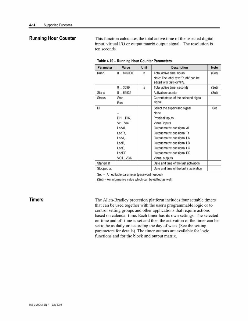
4-14 Supporting Functions
865-UM001A-EN-P – July 2009
Running Hour Counter This function calculates the total active time of the selected digital input, virtual I/O or output matrix output signal. The resolution is ten seconds.
Table 4.10 – Running Hour Counter Parameters
Parameter Value Unit Description Note
Runh 0 ... 876000 h Total active time, hours
Note: The label text "Runh" can be edited with SetPointPS.
(Set)
0 ... 3599 s Total active time, seconds (Set)
Starts 0 ... 65535 Activation counter (Set)
Status Stop
Run
Current status of the selected digital signal
DI
–
DI1 ...DI6,
VI1...VI4,
LedAl,
LedTr,
LedA,
LedB,
LedC,
LedDR
VO1...VO6
Select the supervised signal
None
Physical inputs
Virtual inputs
Output matrix out signal Al
Output matrix out signal Tr
Output matrix out signal LA
Output matrix out signal LB
Output matrix out signal LC
Output matrix out signal DR
Virtual outputs
Set
Started at Date and time of the last activation
Stopped at Date and time of the last inactivation
Set = An editable parameter (password needed)
(Set) = An informative value which can be edited as well.
Timers The Allen-Bradley protection platform includes four settable timers that can be used together with the user's programmable logic or to control setting groups and other applications that require actions based on calendar time. Each timer has its own settings. The selected on-time and off-time is set and then the activation of the timer can be set to be as daily or according the day of week (See the setting parameters for details). The timer outputs are available for logic functions and for the block and output matrix.
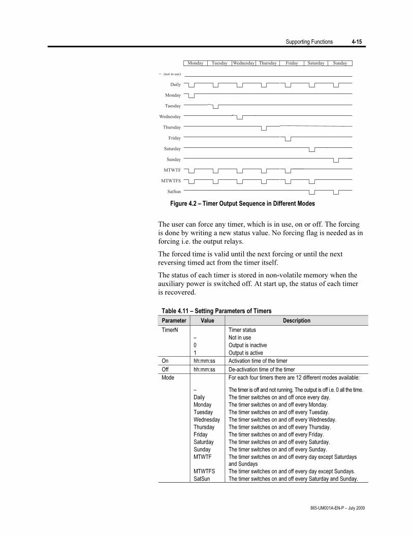
Supporting Functions 4-15
865-UM001A-EN-P – July 2009
Figure 4.2 – Timer Output Sequence in Different Modes
The user can force any timer, which is in use, on or off. The forcing
is done by writing a new status value. No forcing flag is needed as in forcing i.e. the output relays.
The forced time is valid until the next forcing or until the next reversing timed act from the timer itself.
The status of each timer is stored in non-volatile memory when the auxiliary power is switched off. At start up, the status of each timer is recovered.
Table 4.11 – Setting Parameters of Timers
Parameter Value Description
TimerN
–
0
1
Timer status
Not in use
Output is inactive
Output is active
On hh:mm:ss Activation time of the timer
Off hh:mm:ss De-activation time of the timer
For each four timers there are 12 different modes available:
– The timer is off and not running. The output is off i.e. 0 all the time.
Daily The timer switches on and off once every day.
Monday The timer switches on and off every Monday.
Tuesday The timer switches on and off every Tuesday.
Wednesday The timer switches on and off every Wednesday.
Thursday The timer switches on and off every Thursday.
Friday The timer switches on and off every Friday.
Saturday The timer switches on and off every Saturday.
Sunday The timer switches on and off every Sunday.
MTWTF The timer switches on and off every day except Saturdays and Sundays
MTWTFS The timer switches on and off every day except Sundays.
Mode
SatSun The timer switches on and off every Saturday and Sunday.
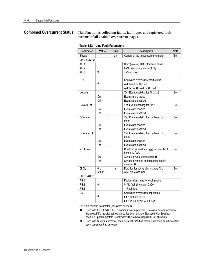
4-16 Supporting Functions
865-UM001A-EN-P – July 2009
Combined Overcurrent Status This function is collecting faults, fault types and registered fault currents of all enabled overcurrent stages.
Table 4.12 – Line Fault Parameters
Parameter Value Unit Description Note
IFltLas xIN Current of the latest overcurrent fault (Set)
LINE ALARM
AlrL1
AlrL2
AlrL3
0
1
Start (=alarm) status for each phase.
0=No start since alarm ClrDly
1=Start is on
OCs 0
1
Combined overcurrent start status.
AlrL1=AlrL2=AlrL3=0
AlrL1=1 orAlrL2=1 or AlrL3=1
LxAlarm
On
Off
‘On’ Event enabling for AlrL1…3
Events are enabled
Events are disabled
Set
LxAlarmOff
On
Off
‘Off’ Event enabling for AlrL1…3
Events are enabled
Events are disabled
Set
OCAlarm
On
Off
‘On’ Event enabling for combined o/c starts
Events are enabled
Events are disabled
Set
OCAlarmOff
On
Off
‘Off’ Event enabling for combined o/c starts
Events are enabled
Events are disabled
Set
IncFltEvnt
On
Off
Disabling several start and trip events of the same fault
Several events are enabled
Several events of an increasing fault is disabled
Set
ClrDly 0 ... 65535
s Duration for active alarm status AlrL1, Alr2, AlrL3 and Ocs
Set
LINE FAULT
FltL1
FltL2
FltL3
0
1
Fault (=trip) status for each phase.
0=No fault since fault ClrDly
1=Fault is on
Oct 0
1
Combined overcurrent trip status.
FltL1=FltL2=FltL3=0
FltL1=1 orFltL2=1 or FltL3=1
Set = An editable parameter (password needed)
Used with IEC 60870-105-103 communication protocol. The alarm screen will show the latest if it's the biggest registered fault current, too. Not used with Spabus, because Spabus masters usually don't like to have unpaired On/Off events.
Used with SPA-bus protocol, because most SPA-bus masters do need an off-event for each corresponding on-event.
Supporting Functions 4-17
865-UM001A-EN-P – July 2009
Table 4.12 – Line Fault Parameters (cont.)
Parameter Value Unit Description Note
LxTrip
On
Off
‘On’ Event enabling for FltL1…3
Events are enabled
Events are disabled
Set
LxTripOff
On
Off
‘Off’ Event enabling for FltL1…3
Events are enabled
Events are disabled
Set
OCTrip
On
Off
‘On’ Event enabling for combined o/c trips
Events are enabled
Events are disabled
Set
OCTripOff
On
Off
'Off' Event enabling for combined o/c starts
Events are enabled
Events are disabled
Set
IncFltEvnt
On
Off
Disabling several events of the same fault
Several events are enabled
Several events of an increasing fault is disabled
Set
ClrDly 0 ... 65535
s Duration for active alarm status FltL1, Flt2, FltL3 and OCt
Set
Set = An editable parameter (password needed)
Used with IEC 60870-105-103 communication protocol. The alarm screen will show the latest if it's the biggest registered fault current, too. Not used with Spabus, because Spabus masters usually don't like to have unpaired On/Off events.
Used with SPA-bus protocol, because most SPA-bus masters do need an off-event for each corresponding on-event.
Self-Supervision The functions of the micro controller and the associated circuitry, as well as the program execution are supervised by means of a separate watchdog circuit. Besides supervising the relay, the watchdog circuit attempts to restart the micro controller in a fault situation. If the restarting fails, the watchdog issues a self-supervision alarm indicating a permanent internal fault.
When the watchdog circuit detects a permanent fault, it always blocks any control of other output relays (except for the self-supervision output relay).
In addition, the internal supply voltages are supervised. Should the auxiliary supply of the relay disappear, an alarm is automatically given because the internal fault (IF) output relay functions on a working current principle. This means that the IF relay is energized when the auxiliary supply is on and no internal fault is detected.

4-18 Supporting Functions
865-UM001A-EN-P – July 2009
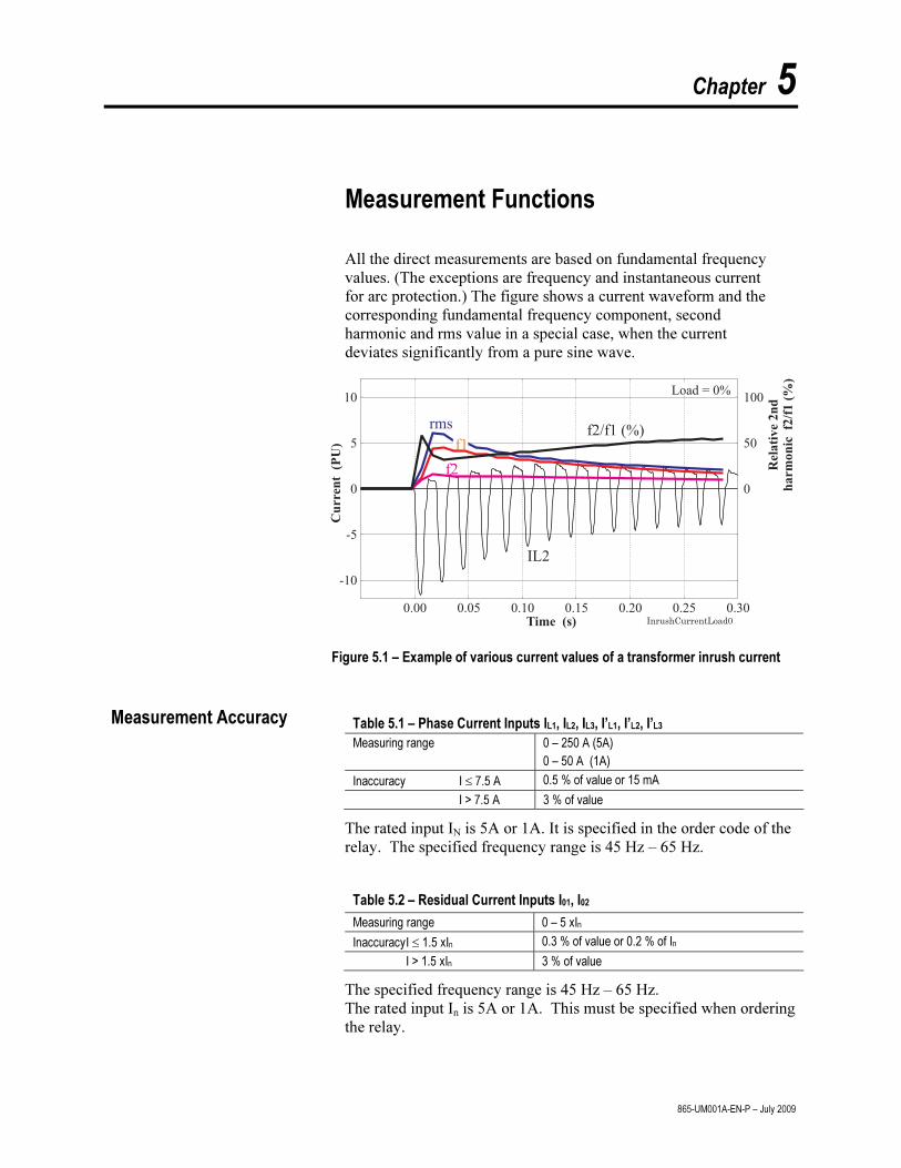
Chapter 5
865-UM001A-EN-P – July 2009
Measurement Functions
All the direct measurements are based on fundamental frequency
values. (The exceptions are frequency and instantaneous current
for arc protection.) The figure shows a current waveform and the
corresponding fundamental frequency component, second
harmonic and rms value in a special case, when the current
deviates significantly from a pure sine wave.
0.00 0.05 0.10 0.15 0.20 0.25 0.30Time (s)
Cu
rre
nt
(PU
)
-10
-5
0
5
10
rms
IL2
f1
f2
Load = 0%
InrushCurrentLoad0
Rela
tive
2n
d
harm
on
icf2
/f1
(%)
0
50
100
f2/f1 (%)
Figure 5.1 – Example of various current values of a transformer inrush current
Table 5.1 – Phase Current Inputs IL1, IL2, IL3, I’L1, I’L2, I’L3
Measuring range 0 – 250 A (5A)
0 – 50 A (1A)
Inaccuracy I ≤ 7.5 A 0.5 % of value or 15 mA
I > 7.5 A 3 % of value
The rated input IN is 5A or 1A. It is specified in the order code of the
relay. The specified frequency range is 45 Hz – 65 Hz.
Table 5.2 – Residual Current Inputs I01, I02
Measuring range 0 – 5 xIn
Inaccuracy I ≤ 1.5 xIn 0.3 % of value or 0.2 % of In
I > 1.5 xIn 3 % of value
The specified frequency range is 45 Hz – 65 Hz.
The rated input In is 5A or 1A. This must be specified when ordering
the relay.
Measurement Accuracy

5-2 Measurement Functions
865-UM001A-EN-P – July 2009
Table 5.3 – Frequency
Measuring range 16 Hz – 75 Hz
Inaccuracy 10 mHz
In the Allen-Bradley 865, frequency is measured from current
signals.
Table 5.4 – THD and Harmonics
Inaccuracy I 0.1 PU 2 % units
Update rate Once a second
The specified frequency range is 45 Hz – 65 Hz.
The device calculates the THDs as percentage of the base
frequency for currents and voltages.
The device calculates the harmonics from the 2nd
to the 15th of
phase currents and voltages. (The 17th harmonic component will
also be shown partly in the value of the 15th harmonic
component. This is due to the nature of digital sampling.)
The harmonic distortion is calculated using equation
1
15
2
2
h
h
THDi
i∑=
= , where
h1 = Fundamental value
h2...15 = Harmonics
Example
h1 = 100 A
h3 = 10 A
h7 = 3 A
h11 = 8 A
%2.13100
8310222
=++
=THD
For reference the RMS value is:
ARMS 9.10083101002222=+++=
Another way to calculate THD is to use the RMS value as
reference instead of the fundamental frequency value. In the
example above the result would then be 13.0 %.
Harmonics and Total Harmonic Distortion (THD)
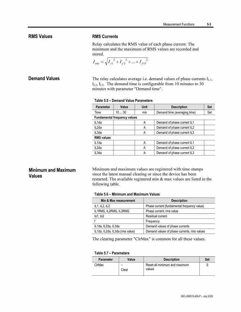
Measurement Functions 5-3
865-UM001A-EN-P – July 2009
RMS Values RMS Currents
Relay calculates the RMS value of each phase current. The
minimum and the maximum of RMS values are recorded and
stored.
2
15
2
2
2
1... fffrms IIII +++=
Demand Values The relay calculates average i.e. demand values of phase currents IL1,
IL2, IL3. The demand time is configurable from 10 minutes to 30
minutes with parameter "Demand time".
Table 5.5 – Demand Value Parameters
Parameter Value Unit Description Set
Time 10 ... 30 min Demand time (averaging time) Set
Fundamental frequency values
IL1da A Demand of phase current IL1
IL2da A Demand of phase current IL2
IL3da A Demand of phase current IL3
RMS values
IL1da A Demand of phase current IL1
IL2da A Demand of phase current IL2
IL3da A Demand of phase current IL3
Minimum and maximum values are registered with time stamps
since the latest manual clearing or since the device has been
restarted. The available registered min & max values are listed in the
following table.
Table 5.6 – Minimum and Maximum Values
Min & Max measurement Description
IL1, IL2, IL3 Phase current (fundamental frequency value)
IL1RMS, IL2RMS, IL3RMS Phase current, rms value
Io1, Io2 Residual current
f Frequency
IL1da, IL2da, IL3da Demand values of phase currents
IL1da, IL2da, IL3da (rms value) Demand values of phase currents, rms values
The clearing parameter "ClrMax" is common for all these values.
Table 5.7 – Parameters
Parameter Value Description Set
ClrMax –
Clear
Reset all minimum and maximum values
S
Minimum and Maximum Values
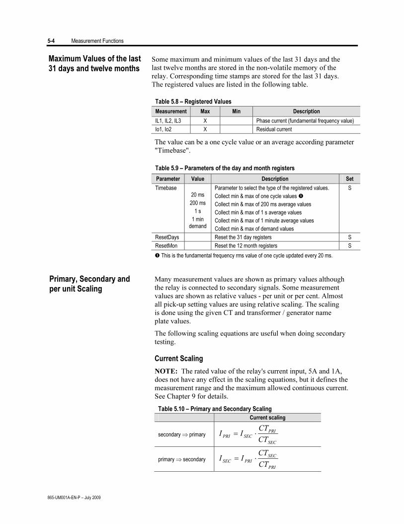
5-4 Measurement Functions
865-UM001A-EN-P – July 2009
Some maximum and minimum values of the last 31 days and the
last twelve months are stored in the non-volatile memory of the
relay. Corresponding time stamps are stored for the last 31 days.
The registered values are listed in the following table.
Table 5.8 – Registered Values
Measurement Max Min Description
IL1, IL2, IL3 X Phase current (fundamental frequency value)
Io1, Io2 X Residual current
The value can be a one cycle value or an average according parameter
"Timebase".
Table 5.9 – Parameters of the day and month registers
Parameter Value Description Set
Timebase 20 ms
200 ms
1 s
1 min demand
Parameter to select the type of the registered values.
Collect min & max of one cycle values
Collect min & max of 200 ms average values
Collect min & max of 1 s average values
Collect min & max of 1 minute average values
Collect min & max of demand values
S
ResetDays Reset the 31 day registers S
ResetMon Reset the 12 month registers S
This is the fundamental frequency rms value of one cycle updated every 20 ms.
Many measurement values are shown as primary values although
the relay is connected to secondary signals. Some measurement
values are shown as relative values - per unit or per cent. Almost
all pick-up setting values are using relative scaling. The scaling
is done using the given CT and transformer / generator name
plate values.
The following scaling equations are useful when doing secondary
testing.
Current Scaling
NOTE: The rated value of the relay's current input, 5A and 1A,
does not have any effect in the scaling equations, but it defines the
measurement range and the maximum allowed continuous current.
See Chapter 9 for details.
Table 5.10 – Primary and Secondary Scaling
Current scaling
secondary ⇒ primary
SEC
PRI
SECPRI
CT
CTII ⋅=
primary ⇒ secondary
PRI
SEC
PRISEC
CT
CTII ⋅=
Maximum Values of the last 31 days and twelve months
Primary, Secondary and per unit Scaling
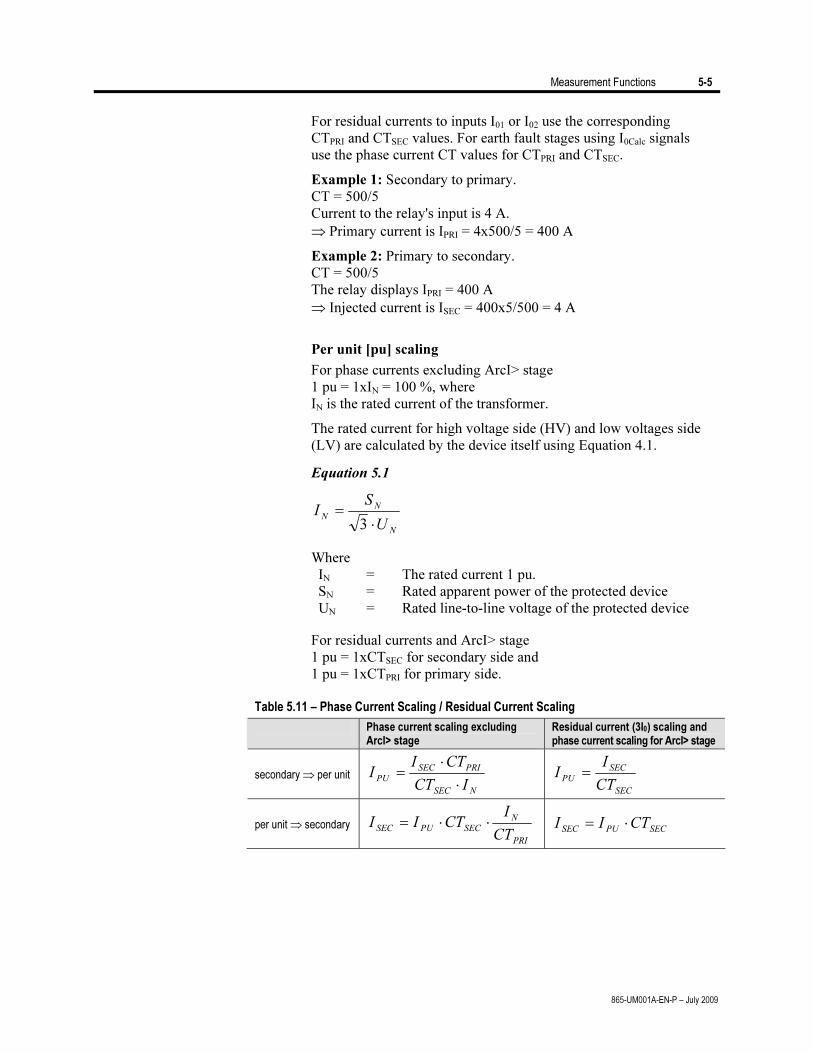
Measurement Functions 5-5
865-UM001A-EN-P – July 2009
For residual currents to inputs I01 or I02 use the corresponding
CTPRI and CTSEC values. For earth fault stages using I0Calc signals
use the phase current CT values for CTPRI and CTSEC.
Example 1: Secondary to primary.
CT = 500/5
Current to the relay's input is 4 A.
⇒ Primary current is IPRI = 4x500/5 = 400 A
Example 2: Primary to secondary.
CT = 500/5
The relay displays IPRI = 400 A
⇒ Injected current is ISEC = 400x5/500 = 4 A
Per unit [pu] scaling
For phase currents excluding ArcI> stage
1 pu = 1xIN = 100 %, where
IN is the rated current of the transformer.
The rated current for high voltage side (HV) and low voltages side
(LV) are calculated by the device itself using Equation 4.1.
Equation 5.1
N
N
N
U
SI
⋅
=
3
Where
IN = The rated current 1 pu.
SN = Rated apparent power of the protected device
UN = Rated line-to-line voltage of the protected device
For residual currents and ArcI> stage
1 pu = 1xCTSEC for secondary side and
1 pu = 1xCTPRI for primary side.
Table 5.11 – Phase Current Scaling / Residual Current Scaling
Phase current scaling excluding ArcI> stage
Residual current (3I0) scaling and phase current scaling for ArcI> stage
secondary ⇒ per unit
NSEC
PRISEC
PU
ICT
CTII
⋅
⋅
=
SEC
SEC
PU
CT
II =
per unit ⇒ secondary
PRI
N
SECPUSEC
CT
ICTII ⋅⋅=
SECPUSECCTII ⋅=
5-6 Measurement Functions
865-UM001A-EN-P – July 2009
Example 1: Secondary to per unit and percent for phase currents
excluding ArcI>.
CTPRI = 150/1
CTSEC = 800/5
SN = 25 MVA
UN = 110 kV
U'N = 21 kV
Current injected to the relay's primary side input is 175 mA and 859
mA for the secondary side input.
The rated current on HV and LV side will be
IN = 25 MVA/ (√3 x 110 kV) = 131.2 A
I'N = 25 MVA/ (√3 x 21 kV) = 687.3 A
⇒ Per unit currents are
IPU = 0.175x150/(1x131.2) = 0.20 pu = 20 %xIN (HV side)
I'PU = 0.859x800/(5x687.3) = 0.20 pu = 20 % (LV side)
Example 2: Secondary to per unit for ArcI>.
CT = 750/5
Current injected to the relay's inputs is 7 A.
⇒ Per unit current is
IPU = 7/5 = 1.4 pu = 140 %
Example 3: Per unit and percent to secondary for phase currents
excluding ArcI>.
CTPRI = 150/1
CTSEC = 800/5
SN = 25 MVA
UN = 110 kV
U'N = 21 kV
The relay setting is 0.20 pu = 20 %xIN.
The rated current on HV and LV side will be same as in example 1.
⇒ The corresponding secondary currents are
ISEC = 0.20xIN = 0.20x131.2x1/150 = 175 mA (HV side)
I'SEC = 0.20xI'N = 0.20x687.3x5/800 = 859 mA (LV side)
Example 4: Per unit to secondary for ArcI>.
CT = 750/5
The relay setting is 2 pu = 200 %.
⇒ Secondary current is
ISEC = 2x5 = 10 A
Example 5: Secondary to per unit for residual current.
Input is I01 or I02.
CT0 = 50/1
Current injected to the relay's input is 30 mA.
⇒ Per unit current is
IPU = 0.03/1 = 0.03 pu = 3 %
Primary, Secondary and per unit Scaling (cont.)
Measurement Functions 5-7
865-UM001A-EN-P – July 2009
Example 6: Per unit to secondary for residual current.
Input is I01 or I02.
CT0 = 50/1
The relay setting is 0.03 pu = 3 %.
⇒ Secondary current is
ISEC = 0.03x1 = 30 mA
Example 7: Secondary to per unit for residual current.
Input is I0Calc.
CT = 750/5
Currents injected to the relay's IL1 input is 0.5 A.
IL2 = IL3 = 0.
⇒ Per unit current is
IPU = 0.5/5 = 0.1 pu = 10 %
Example 8: Per unit to secondary for residual current.
Input is I0Calc.
CT = 750/5
The relay setting is 0.1 pu = 10 %.
⇒ If IL2 = IL3 = 0, then secondary current to IL1 is
ISEC = 0.1x5 = 0.5 A

5-8 Measurement Functions
865-UM001A-EN-P – July 2009
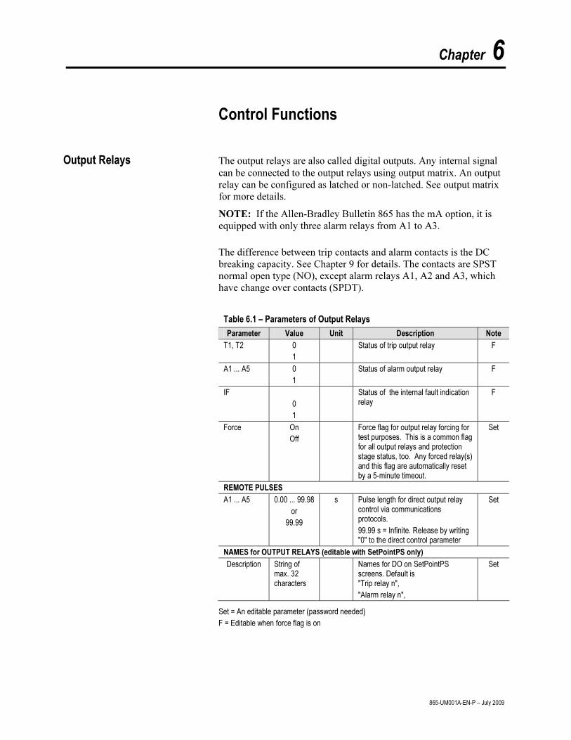
Chapter 6
865-UM001A-EN-P – July 2009
Control Functions
Output Relays The output relays are also called digital outputs. Any internal signal can be connected to the output relays using output matrix. An output relay can be configured as latched or non-latched. See output matrix for more details.
NOTE: If the Allen-Bradley Bulletin 865 has the mA option, it is equipped with only three alarm relays from A1 to A3.
The difference between trip contacts and alarm contacts is the DC
breaking capacity. See Chapter 9 for details. The contacts are SPST normal open type (NO), except alarm relays A1, A2 and A3, which have change over contacts (SPDT).
Table 6.1 – Parameters of Output Relays
Parameter Value Unit Description Note
T1, T2 0
1
Status of trip output relay F
A1 ... A5 0
1
Status of alarm output relay F
IF
0
1
Status of the internal fault indication relay
F
Force On
Off
Force flag for output relay forcing for test purposes. This is a common flag for all output relays and protection stage status, too. Any forced relay(s) and this flag are automatically reset by a 5-minute timeout.
Set
REMOTE PULSES
A1 ... A5 0.00 ... 99.98
or
99.99
s Pulse length for direct output relay control via communications protocols.
99.99 s = Infinite. Release by writing "0" to the direct control parameter
Set
NAMES for OUTPUT RELAYS (editable with SetPointPS only)
Description String of max. 32 characters
Names for DO on SetPointPS screens. Default is "Trip relay n",
"Alarm relay n",
Set
Set = An editable parameter (password needed)
F = Editable when force flag is on
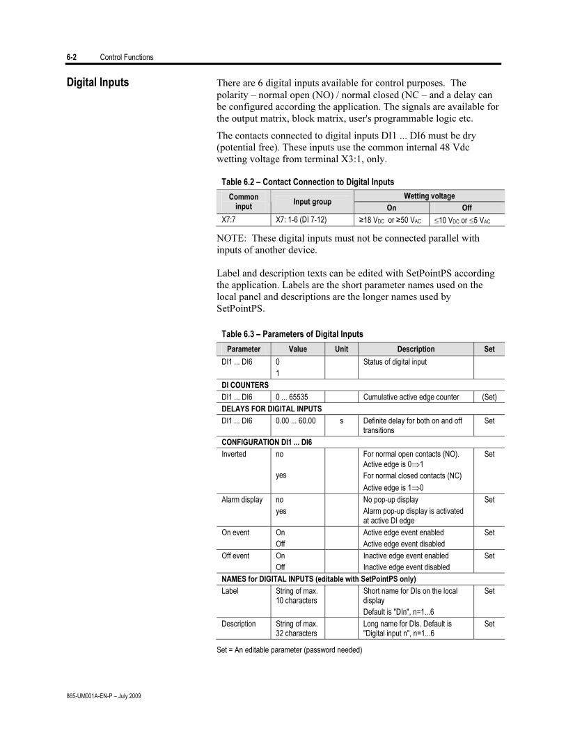
6-2 Control Functions
865-UM001A-EN-P – July 2009
Digital Inputs There are 6 digital inputs available for control purposes. The polarity – normal open (NO) / normal closed (NC – and a delay can be configured according the application. The signals are available for the output matrix, block matrix, user's programmable logic etc.
The contacts connected to digital inputs DI1 ... DI6 must be dry (potential free). These inputs use the common internal 48 Vdc wetting voltage from terminal X3:1, only.
Table 6.2 – Contact Connection to Digital Inputs
Wetting voltage Common input
Input group On Off
X7:7 X7: 1-6 (DI 7-12) ≥18 VDC or ≥50 VAC ≤10 VDC or ≤5 VAC
NOTE: These digital inputs must not be connected parallel with inputs of another device.
Label and description texts can be edited with SetPointPS according
the application. Labels are the short parameter names used on the local panel and descriptions are the longer names used by SetPointPS.
Table 6.3 – Parameters of Digital Inputs
Parameter Value Unit Description Set
DI1 ... DI6 0
1
Status of digital input
DI COUNTERS
DI1 ... DI6 0 ... 65535 Cumulative active edge counter (Set)
DELAYS FOR DIGITAL INPUTS
DI1 ... DI6 0.00 ... 60.00 s Definite delay for both on and off transitions
Set
CONFIGURATION DI1 ... DI6
Inverted no
yes
For normal open contacts (NO).
Active edge is 0⇒1
For normal closed contacts (NC)
Active edge is 1⇒0
Set
Alarm display no
yes
No pop-up display
Alarm pop-up display is activated at active DI edge
Set
On event On
Off
Active edge event enabled
Active edge event disabled
Set
Off event On
Off
Inactive edge event enabled
Inactive edge event disabled
Set
NAMES for DIGITAL INPUTS (editable with SetPointPS only)
Label String of max. 10 characters
Short name for DIs on the local display
Default is "DIn", n=1...6
Set
Description String of max. 32 characters
Long name for DIs. Default is "Digital input n", n=1...6
Set
Set = An editable parameter (password needed)

Control Functions 6-3
865-UM001A-EN-P – July 2009
Table 6.4 – Summary of Digital Inputs
DI Terminal Operating voltage Availability
X3:1 48VDC supply for DI1…6
1 X3:2
2 X3:3
3 X3:4
4 X3:5
5 X3:6
6 X3:7
Internal 48VDC
Allen-Bradley 865
19 X6:1…2 External 18…865 VDC
50…250 VAC ARC card with 2 DIs
Virtual Inputs and Outputs There are four virtual inputs and six virtual outputs. The four virtual inputs acts like normal digital inputs. The state of the virtual input can be changed from display, communication bus and from SetPointPS. For example setting groups can be changed using virtual inputs.
Table 6.5 – Parameters of Virtual Inputs
Parameter Value Unit Description Set
VI1 ... VI4 0
1
Status of virtual input
Events On
Off
Event enabling Set
NAMES for VIRTUAL INPUTS (editable with SetPointPS only)
Label String of max. 10 characters
Short name for VIs on the local display
Default is "VIn", n=1...4
Set
Description String of max. 32 characters
Long name for VIs. Default is "Virtual input n", n=1...4
Set
Set = An editable parameter (password needed)
The six virtual outputs do act like output relays, but there are no physical contacts. Virtual outputs are shown in the output matrix and the block matrix. Virtual outputs can be used with the user's programmable logic and to change the active setting group etc.
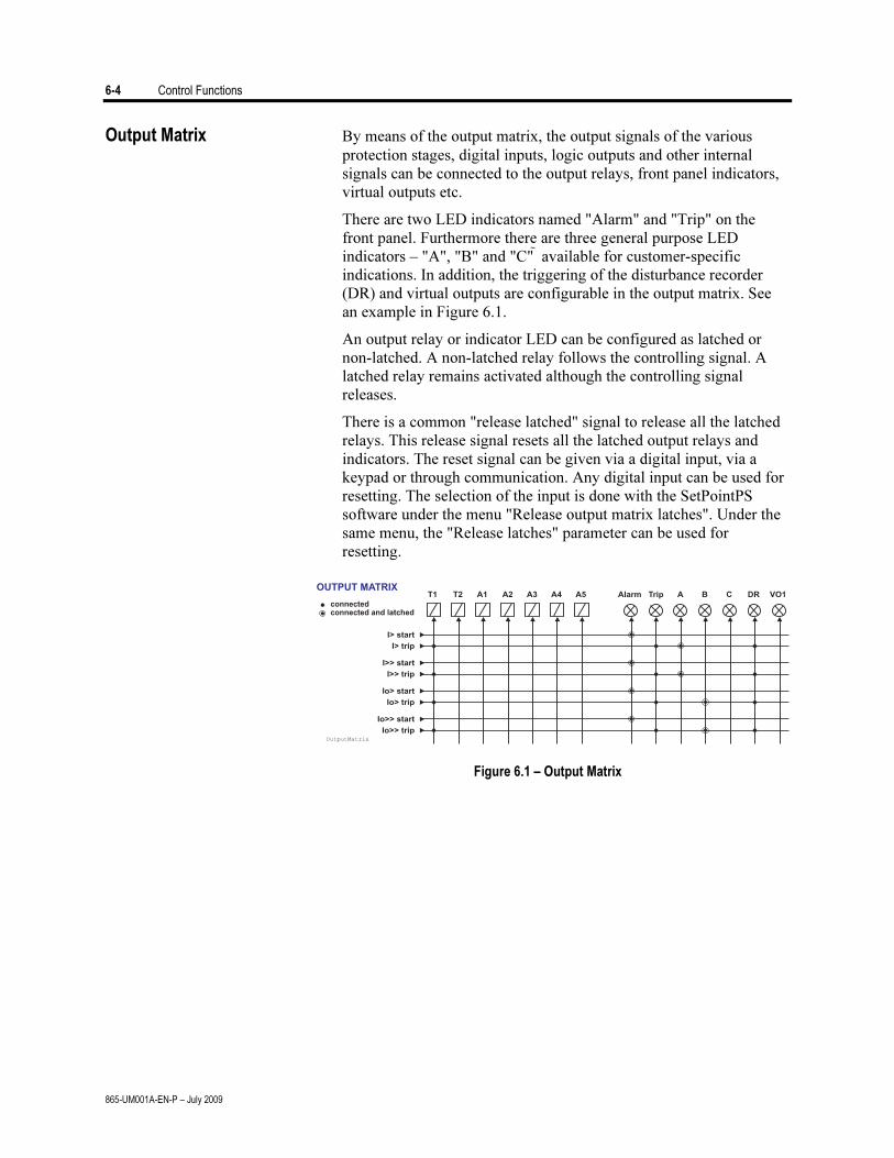
6-4 Control Functions
865-UM001A-EN-P – July 2009
Output Matrix By means of the output matrix, the output signals of the various
protection stages, digital inputs, logic outputs and other internal signals can be connected to the output relays, front panel indicators, virtual outputs etc.
There are two LED indicators named "Alarm" and "Trip" on the front panel. Furthermore there are three general purpose LED indicators – "A", "B" and "C" available for customer-specific indications. In addition, the triggering of the disturbance recorder (DR) and virtual outputs are configurable in the output matrix. See an example in Figure 6.1.
An output relay or indicator LED can be configured as latched or non-latched. A non-latched relay follows the controlling signal. A latched relay remains activated although the controlling signal releases.
There is a common "release latched" signal to release all the latched relays. This release signal resets all the latched output relays and indicators. The reset signal can be given via a digital input, via a keypad or through communication. Any digital input can be used for resetting. The selection of the input is done with the SetPointPS software under the menu "Release output matrix latches". Under the same menu, the "Release latches" parameter can be used for resetting.
OUTPUT MATRIX
connected
I> start
I>> start
Io> start
Io>> start
I> trip
I>> trip
Io> trip
Io>> trip
T1 T2 A1 A2 A3 A4 A5 Alarm Trip A B C DR VO1
connected and latched
OutputMatrix
Figure 6.1 – Output Matrix
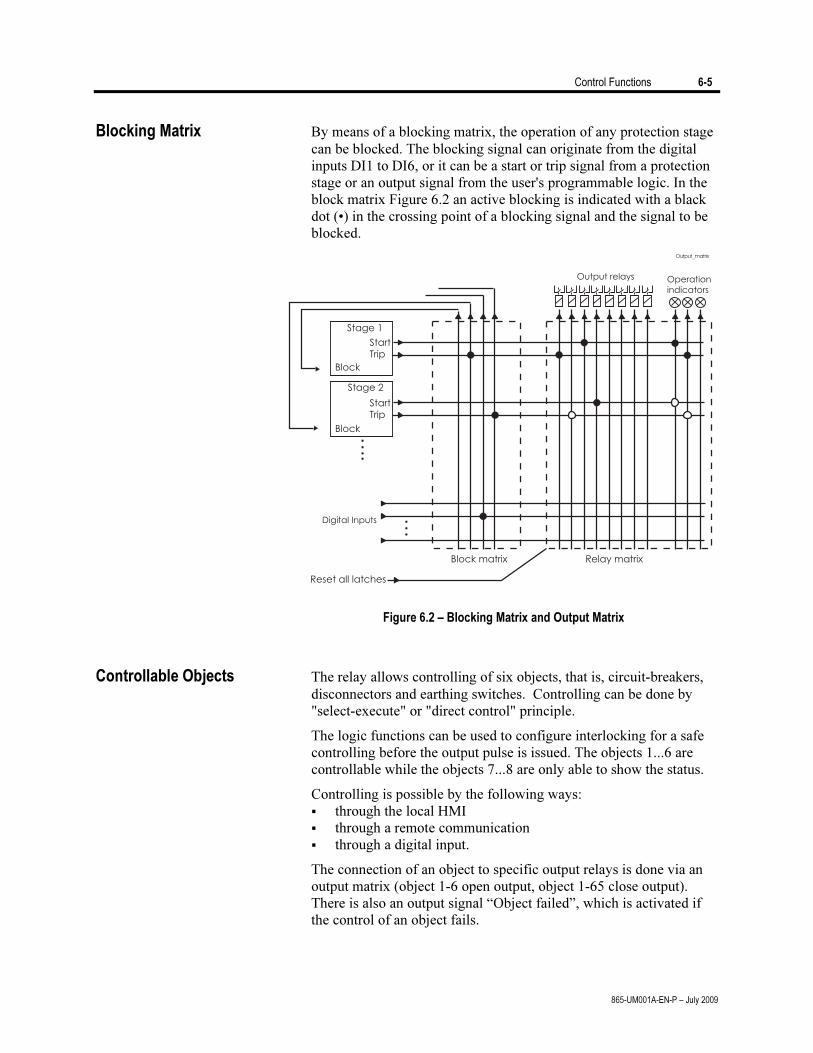
Control Functions 6-5
865-UM001A-EN-P – July 2009
Blocking Matrix By means of a blocking matrix, the operation of any protection stage can be blocked. The blocking signal can originate from the digital inputs DI1 to DI6, or it can be a start or trip signal from a protection stage or an output signal from the user's programmable logic. In the block matrix Figure 6.2 an active blocking is indicated with a black dot (•) in the crossing point of a blocking signal and the signal to be blocked.
Figure 6.2 – Blocking Matrix and Output Matrix
Controllable Objects The relay allows controlling of six objects, that is, circuit-breakers, disconnectors and earthing switches. Controlling can be done by "select-execute" or "direct control" principle.
The logic functions can be used to configure interlocking for a safe controlling before the output pulse is issued. The objects 1...6 are controllable while the objects 7...8 are only able to show the status.
Controlling is possible by the following ways: through the local HMI through a remote communication through a digital input.
The connection of an object to specific output relays is done via an output matrix (object 1-6 open output, object 1-65 close output). There is also an output signal “Object failed”, which is activated if the control of an object fails.
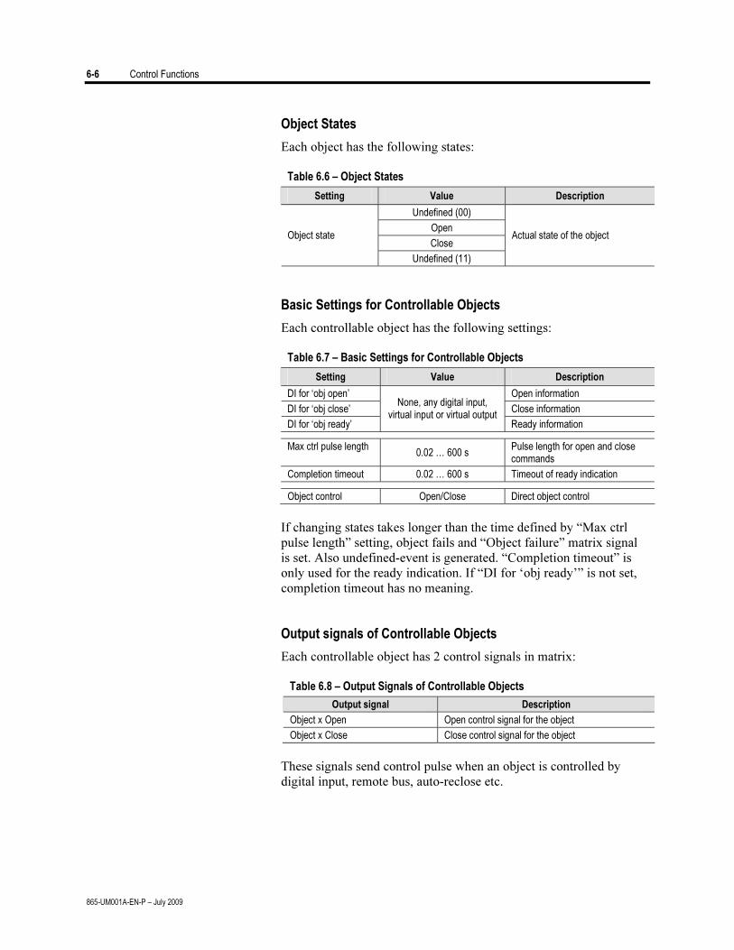
6-6 Control Functions
865-UM001A-EN-P – July 2009
Object States
Each object has the following states:
Table 6.6 – Object States
Setting Value Description
Undefined (00)
Open
Close Object state
Undefined (11)
Actual state of the object
Basic Settings for Controllable Objects
Each controllable object has the following settings:
Table 6.7 – Basic Settings for Controllable Objects
Setting Value Description
DI for ‘obj open’ Open information
DI for ‘obj close’ Close information
DI for ‘obj ready’
None, any digital input, virtual input or virtual output
Ready information
Max ctrl pulse length 0.02 … 600 s
Pulse length for open and close commands
Completion timeout 0.02 … 600 s Timeout of ready indication
Object control Open/Close Direct object control
If changing states takes longer than the time defined by “Max ctrl
pulse length” setting, object fails and “Object failure” matrix signal is set. Also undefined-event is generated. “Completion timeout” is only used for the ready indication. If “DI for ‘obj ready’” is not set, completion timeout has no meaning.
Output signals of Controllable Objects
Each controllable object has 2 control signals in matrix:
Table 6.8 – Output Signals of Controllable Objects
Output signal Description
Object x Open Open control signal for the object
Object x Close Close control signal for the object
These signals send control pulse when an object is controlled by
digital input, remote bus, auto-reclose etc.
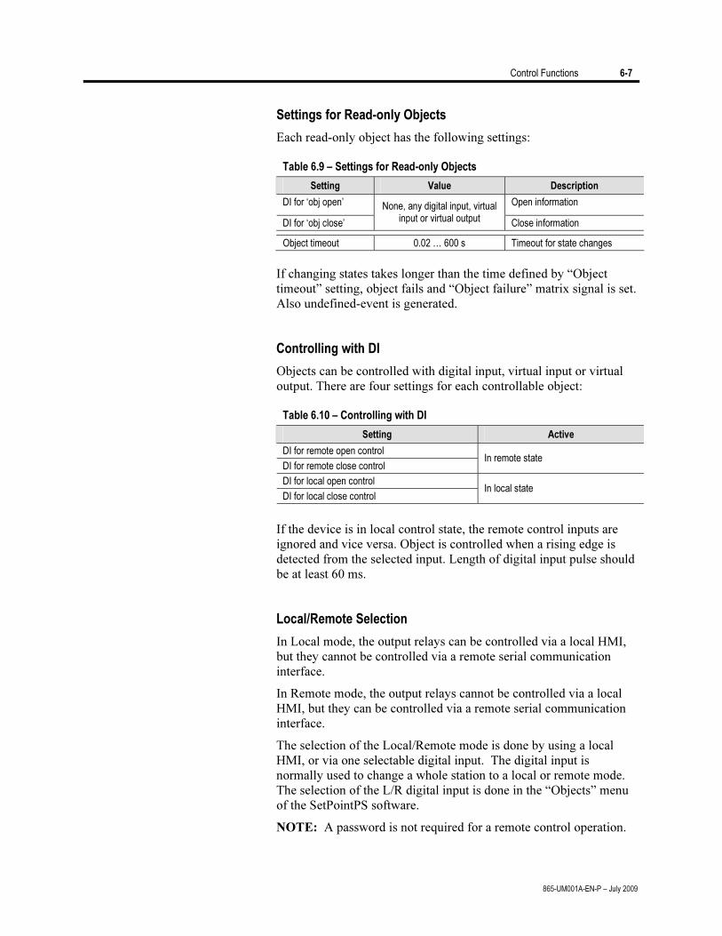
Control Functions 6-7
865-UM001A-EN-P – July 2009
Settings for Read-only Objects
Each read-only object has the following settings:
Table 6.9 – Settings for Read-only Objects
Setting Value Description
DI for ‘obj open’ Open information
DI for ‘obj close’
None, any digital input, virtual input or virtual output Close information
Object timeout 0.02 … 600 s Timeout for state changes
If changing states takes longer than the time defined by “Object
timeout” setting, object fails and “Object failure” matrix signal is set. Also undefined-event is generated.
Controlling with DI
Objects can be controlled with digital input, virtual input or virtual output. There are four settings for each controllable object:
Table 6.10 – Controlling with DI
Setting Active
DI for remote open control
DI for remote close control In remote state
DI for local open control
DI for local close control In local state
If the device is in local control state, the remote control inputs are
ignored and vice versa. Object is controlled when a rising edge is detected from the selected input. Length of digital input pulse should be at least 60 ms.
Local/Remote Selection
In Local mode, the output relays can be controlled via a local HMI, but they cannot be controlled via a remote serial communication interface.
In Remote mode, the output relays cannot be controlled via a local HMI, but they can be controlled via a remote serial communication interface.
The selection of the Local/Remote mode is done by using a local HMI, or via one selectable digital input. The digital input is normally used to change a whole station to a local or remote mode. The selection of the L/R digital input is done in the “Objects” menu of the SetPointPS software.
NOTE: A password is not required for a remote control operation.

6-8 Control Functions
865-UM001A-EN-P – July 2009
Logic Functions The relay supports customer-defined programmable logic for
Boolean signals. The logic is designed by using the SetPointPS setting tool and downloaded to the relay. Functions available are: AND OR XOR NOT COUNTERs RS & D flip-flops
Maximum number of outputs is 20. Maximum number of input gates
is 31. An input gate can include any number of inputs.
For detailed information, please refer to the SetPointPS manual (857-PM001A-EN-P).
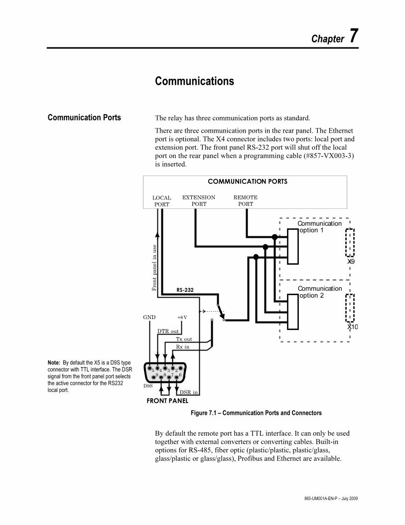
Chapter 7
865-UM001A-EN-P – July 2009
Communications
Communication Ports The relay has three communication ports as standard.
There are three communication ports in the rear panel. The Ethernet
port is optional. The X4 connector includes two ports: local port and
extension port. The front panel RS-232 port will shut off the local
port on the rear panel when a programming cable (#857-VX003-3)
is inserted.
Note: By default the X5 is a D9S type connector with TTL interface. The DSR signal from the front panel port selects the active connector for the RS232 local port.
12345
6789
D9S
Frontpanelin
use
Rx in
DSR in
LOCAL
PORT
EXTENSION
PORT
REMOTE
PORT
Tx out
RS-232
DTR out
+8 VGND
FRONT PANEL
COMMUNICATION PORTS
Communicationoption 1
Communicationoption 2
X9
X10
Figure 7.1 – Communication Ports and Connectors
By default the remote port has a TTL interface. It can only be used
together with external converters or converting cables. Built-in
options for RS-485, fiber optic (plastic/plastic, plastic/glass,
glass/plastic or glass/glass), Profibus and Ethernet are available.
7-2 Communications
865-UM001A-EN-P – July 2009
Local Port X4
The local port has two connectors:
On the front panel
X4 the rear panel (D9S pins 2, 3 and 5)
Only one can be used at a time.
NOTE: The extension port is locating in the same X4 connector.
NOTE: When the 857-VX003-3 cable is inserted to the front panel
connector it activates the front panel port and disables the rear panel
local port by connecting the DTR pin 6 and DSR pin 4 together. See
Figure 7.1.
Protocol for the Local Port
The front panel port is always using the command line protocol for
SetPointPS regardless of the selected protocol for the rear panel local
port.
If other than "None" protocol is selected for the rear panel local port,
the front panel connector, when activated, is still using the plain
command line interface with the original speed, parity etc. For
example if the rear panel local port is used for remote SetPointPS
communication using SPA-bus default 9600/7E1, it is possible to
temporarily connect a PC with SetPointPS to the front panel
connector with the default 38400/8N1.
While the front panel connector is in use, the rear panel local port is
disabled. The communication parameter display on the local display
will show the active parameter values for the local port.
Physical Interface
The physical interface of this port is RS-232.
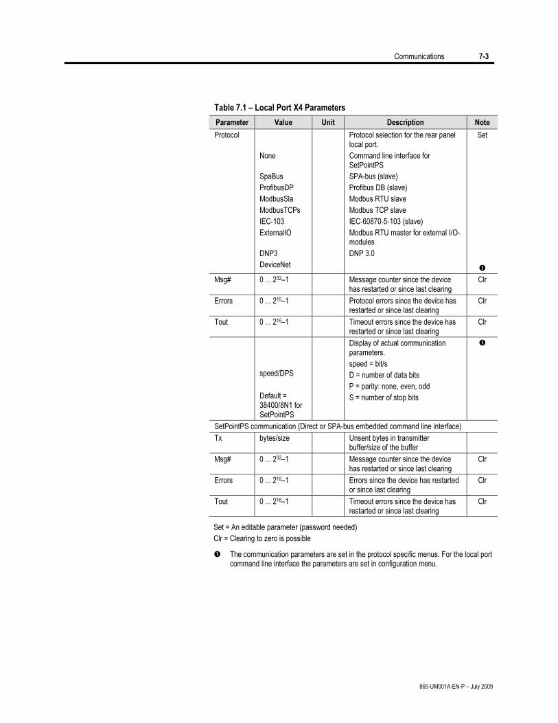
Communications 7-3
865-UM001A-EN-P – July 2009
Table 7.1 – Local Port X4 Parameters
Parameter Value Unit Description Note
Protocol
None
SpaBus
ProfibusDP
ModbusSla
ModbusTCPs
IEC-103
ExternalIO
DNP3
DeviceNet
Protocol selection for the rear panel local port.
Command line interface for SetPointPS
SPA-bus (slave)
Profibus DB (slave)
Modbus RTU slave
Modbus TCP slave
IEC-60870-5-103 (slave)
Modbus RTU master for external I/O-modules
DNP 3.0
Set
Msg# 0 ... 232–1 Message counter since the device has restarted or since last clearing
Clr
Errors 0 ... 216–1 Protocol errors since the device has restarted or since last clearing
Clr
Tout 0 ... 216–1 Timeout errors since the device has restarted or since last clearing
Clr
speed/DPS
Default = 38400/8N1 for SetPointPS
Display of actual communication parameters.
speed = bit/s
D = number of data bits
P = parity: none, even, odd
S = number of stop bits
SetPointPS communication (Direct or SPA-bus embedded command line interface)
Tx bytes/size Unsent bytes in transmitter buffer/size of the buffer
Msg# 0 ... 232–1 Message counter since the device has restarted or since last clearing
Clr
Errors 0 ... 216–1 Errors since the device has restarted or since last clearing
Clr
Tout 0 ... 216–1 Timeout errors since the device has restarted or since last clearing
Clr
Set = An editable parameter (password needed)
Clr = Clearing to zero is possible
The communication parameters are set in the protocol specific menus. For the local port command line interface the parameters are set in configuration menu.
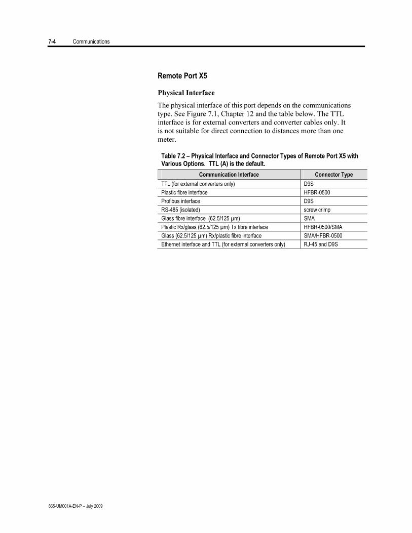
7-4 Communications
865-UM001A-EN-P – July 2009
Remote Port X5
Physical Interface
The physical interface of this port depends on the communications
type. See Figure 7.1, Chapter 12 and the table below. The TTL
interface is for external converters and converter cables only. It
is not suitable for direct connection to distances more than one
meter.
Table 7.2 – Physical Interface and Connector Types of Remote Port X5 with Various Options. TTL (A) is the default.
Communication Interface Connector Type
TTL (for external converters only) D9S
Plastic fibre interface HFBR-0500
Profibus interface D9S
RS-485 (isolated) screw crimp
Glass fibre interface (62.5/125 µm) SMA
Plastic Rx/glass (62.5/125 µm) Tx fibre interface HFBR-0500/SMA
Glass (62.5/125 µm) Rx/plastic fibre interface SMA/HFBR-0500
Ethernet interface and TTL (for external converters only) RJ-45 and D9S
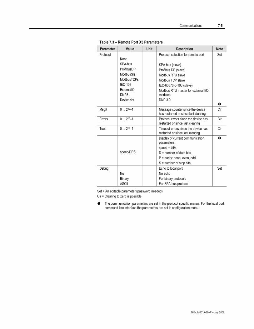
Communications 7-5
865-UM001A-EN-P – July 2009
Table 7.3 – Remote Port X5 Parameters
Parameter Value Unit Description Note
Protocol None
SPA-bus
ProfibusDP
ModbusSla
ModbusTCPs
IEC-103
ExternalIO
DNP3
DeviceNet
Protocol selection for remote port
–
SPA-bus (slave)
Profibus DB (slave)
Modbus RTU slave
Modbus TCP slave
IEC-60870-5-103 (slave)
Modbus RTU master for external I/O-modules
DNP 3.0
Set
Msg# 0 ... 232–1 Message counter since the device has restarted or since last clearing
Clr
Errors 0 ... 216–1 Protocol errors since the device has restarted or since last clearing
Clr
Tout 0 ... 216–1 Timeout errors since the device has restarted or since last clearing
Clr
speed/DPS
Display of current communication parameters.
speed = bit/s
D = number of data bits
P = parity: none, even, odd
S = number of stop bits
Debug
No
Binary
ASCII
Echo to local port
No echo
For binary protocols
For SPA-bus protocol
Set
Set = An editable parameter (password needed)
Clr = Clearing to zero is possible
The communication parameters are set in the protocol specific menus. For the local port command line interface the parameters are set in configuration menu.
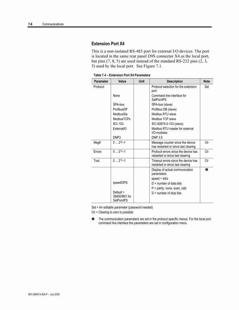
7-6 Communications
865-UM001A-EN-P – July 2009
Extension Port X4
This is a non-isolated RS-485 port for external I/O devices. The port
is located in the same rear panel D9S connector X4 as the local port,
but pins (7, 8, 5) are used instead of the standard RS-232 pins (2, 3,
5) used by the local port. See Figure 7.1.
Table 7.4 – Extension Port X4 Parameters
Parameter Value Unit Description Note
Protocol
None
SPA-bus
ProfibusDP
ModbusSla
ModbusTCPs
IEC-103
ExternalIO
DNP3
Protocol selection for the extension port.
Command line interface for SetPointPS
SPA-bus (slave)
Profibus DB (slave)
Modbus RTU slave
Modbus TCP slave
IEC-60870-5-103 (slave)
Modbus RTU master for external I/O-modules
DNP 3.0
Set
Msg# 0 ... 232–1 Message counter since the device has restarted or since last clearing
Clr
Errors 0 ... 216–1 Protocol errors since the device has restarted or since last clearing
Clr
Tout 0 ... 216–1 Timeout errors since the device has restarted or since last clearing
Clr
speed/DPS
Default = 38400/8N1 for SetPointPS
Display of actual communication parameters.
speed = bit/s
D = number of data bits
P = parity: none, even, odd
S = number of stop bits
Set = An editable parameter (password needed)
Clr = Clearing to zero is possible
The communication parameters are set in the protocol specific menus. For the local port command line interface the parameters are set in configuration menu.
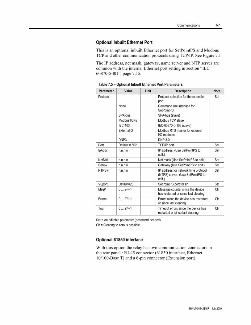
Communications 7-7
865-UM001A-EN-P – July 2009
Optional Inbuilt Ethernet Port
This is an optional inbuilt Ethernet port for SetPointPS and Modbus
TCP and other communication protocols using TCP/IP. See Figure 7.1
The IP address, net mask, gateway, name server and NTP server are
common with the internal Ethernet port setting in section “IEC
60870-5-l01”, page 7.15.
Table 7.5 – Optional Inbuilt Ethernet Port Parameters
Parameter Value Unit Description Note
Protocol
None
SPA-bus
ModbusTCPs
IEC-103
ExternalIO
DNP3
Protocol selection for the extension port.
Command line interface for SetPointPS
SPA-bus (slave)
Modbus TCP slave
IEC-60870-5-103 (slave)
Modbus RTU master for external I/O-modules
DNP 3.0
Set
Port Default = 502 TCP/IP port. Set
IpAddr n.n.n.n IP address. (Use SetPointPS to edit.)
Set
NetMsk n.n.n.n Net mask (Use SetPointPS to edit.) Set
Gatew n.n.n.n Gateway (Use SetPointPS to edit.) Set
NTPSvr n.n.n.n IP address for network time protocol (NTPS) server. (Use SetPointPS to edit.)
Set
VSport Default=23 SetPointPS port for IP Set
Msg# 0 ... 232–1 Message counter since the device has restarted or since last clearing
Clr
Errors 0 ... 216–1 Errors since the device has restarted or since last clearing
Clr
Tout 0 ... 216–1 Timeout errors since the device has restarted or since last clearing
Clr
Set = An editable parameter (password needed)
Clr = Clearing to zero is possible
Optional 61850 interface
With this option the relay has two communication connectors in
the rear panel : RJ-45 connector (61850 interface, Ethernet
10/100-Base T) and a 6-pin connector (Extension port).
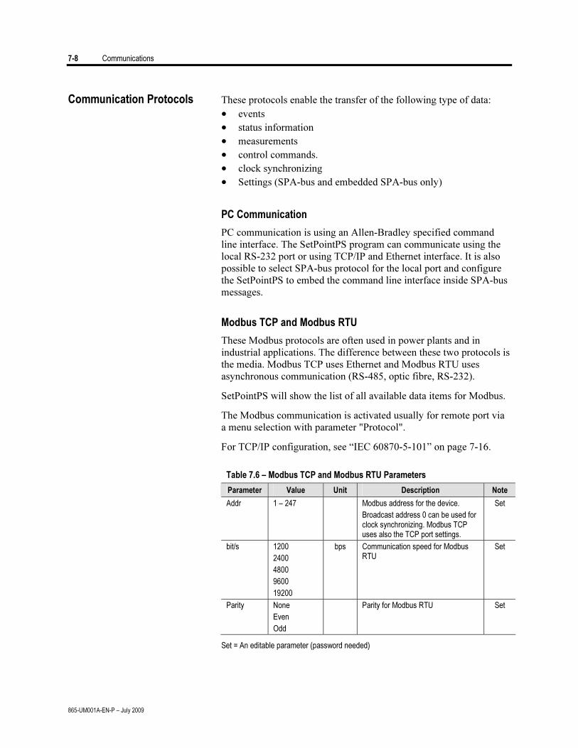
7-8 Communications
865-UM001A-EN-P – July 2009
Communication Protocols These protocols enable the transfer of the following type of data:
• events
• status information
• measurements
• control commands.
• clock synchronizing
• Settings (SPA-bus and embedded SPA-bus only)
PC Communication
PC communication is using an Allen-Bradley specified command
line interface. The SetPointPS program can communicate using the
local RS-232 port or using TCP/IP and Ethernet interface. It is also
possible to select SPA-bus protocol for the local port and configure
the SetPointPS to embed the command line interface inside SPA-bus
messages.
Modbus TCP and Modbus RTU
These Modbus protocols are often used in power plants and in
industrial applications. The difference between these two protocols is
the media. Modbus TCP uses Ethernet and Modbus RTU uses
asynchronous communication (RS-485, optic fibre, RS-232).
SetPointPS will show the list of all available data items for Modbus.
The Modbus communication is activated usually for remote port via
a menu selection with parameter "Protocol".
For TCP/IP configuration, see “IEC 60870-5-101” on page 7-16.
Table 7.6 – Modbus TCP and Modbus RTU Parameters
Parameter Value Unit Description Note
Addr 1 – 247
Modbus address for the device.
Broadcast address 0 can be used for clock synchronizing. Modbus TCP uses also the TCP port settings.
Set
bit/s 1200
2400
4800
9600
19200
bps Communication speed for Modbus RTU
Set
Parity None
Even
Odd
Parity for Modbus RTU Set
Set = An editable parameter (password needed)
Communications 7-9
865-UM001A-EN-P – July 2009
Profibus DP
The Profibus DP protocol is widely used in industry worldwide. An
external or internal Profibus module is required.
Device profile "Continuous Mode"
In this mode the device is sending a configured set of data
parameters continuously to the Profibus DP master. The benefit of
this mode is the speed and easy access to the data in the Profibus
master. The drawback is the maximum buffer size of 128 bytes,
which limits the number of data items transferred to the master.
Some PLCs have their own limitation for the Profibus buffer size,
which may further limit the number of transferred data items.
Device profile "Request mode"
Using the request mode it is possible to read all the available data
from the Allen-Bradley device and still use only a very short buffer
for Profibus data transfer. The drawback is the slower overall speed
of the data transfer and the need of increased data processing at the
Profibus master as every data item must be separately requested by
the master.
NOTE: In request more it is not possible to read continuously only
one single data item. At least two data items must be read in turn to
get updated data from the device.
Available Data
SetPointPS will show the list of all available data items for both
modes.
The Profibus DP communication is activated usually for remote port
via a menu selection with parameter "Protocol".
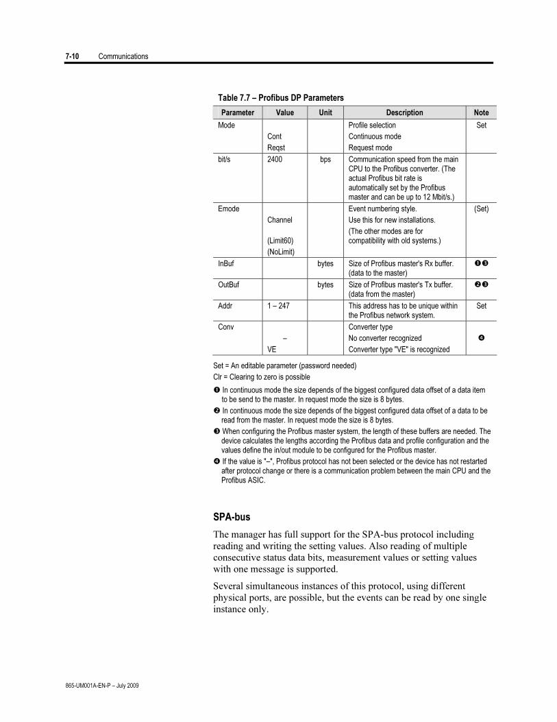
7-10 Communications
865-UM001A-EN-P – July 2009
Table 7.7 – Profibus DP Parameters
Parameter Value Unit Description Note
Mode
Cont
Reqst
Profile selection
Continuous mode
Request mode
Set
bit/s 2400 bps Communication speed from the main CPU to the Profibus converter. (The actual Profibus bit rate is automatically set by the Profibus master and can be up to 12 Mbit/s.)
Emode
Channel
(Limit60)
(NoLimit)
Event numbering style.
Use this for new installations.
(The other modes are for compatibility with old systems.)
(Set)
InBuf bytes Size of Profibus master's Rx buffer. (data to the master)
OutBuf bytes Size of Profibus master's Tx buffer. (data from the master)
Addr 1 – 247
This address has to be unique within the Profibus network system.
Set
Conv
–
VE
Converter type
No converter recognized
Converter type "VE" is recognized
Set = An editable parameter (password needed)
Clr = Clearing to zero is possible
In continuous mode the size depends of the biggest configured data offset of a data item to be send to the master. In request mode the size is 8 bytes.
In continuous mode the size depends of the biggest configured data offset of a data to be read from the master. In request mode the size is 8 bytes.
When configuring the Profibus master system, the length of these buffers are needed. The device calculates the lengths according the Profibus data and profile configuration and the values define the in/out module to be configured for the Profibus master.
If the value is "–", Profibus protocol has not been selected or the device has not restarted after protocol change or there is a communication problem between the main CPU and the Profibus ASIC.
SPA-bus
The manager has full support for the SPA-bus protocol including
reading and writing the setting values. Also reading of multiple
consecutive status data bits, measurement values or setting values
with one message is supported.
Several simultaneous instances of this protocol, using different
physical ports, are possible, but the events can be read by one single
instance only.
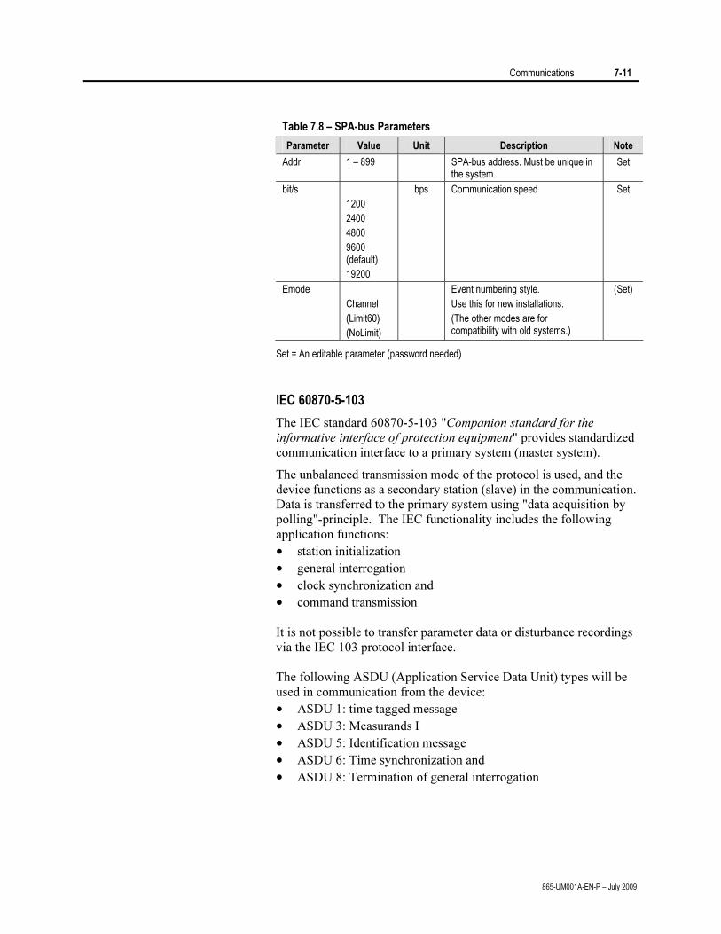
Communications 7-11
865-UM001A-EN-P – July 2009
Table 7.8 – SPA-bus Parameters
Parameter Value Unit Description Note
Addr 1 – 899 SPA-bus address. Must be unique in the system.
Set
bit/s
1200
2400
4800
9600 (default)
19200
bps Communication speed Set
Emode
Channel
(Limit60)
(NoLimit)
Event numbering style.
Use this for new installations.
(The other modes are for compatibility with old systems.)
(Set)
Set = An editable parameter (password needed)
IEC 60870-5-103
The IEC standard 60870-5-103 "Companion standard for the
informative interface of protection equipment" provides standardized
communication interface to a primary system (master system).
The unbalanced transmission mode of the protocol is used, and the
device functions as a secondary station (slave) in the communication.
Data is transferred to the primary system using "data acquisition by
polling"-principle. The IEC functionality includes the following
application functions:
• station initialization
• general interrogation
• clock synchronization and
• command transmission
It is not possible to transfer parameter data or disturbance recordings
via the IEC 103 protocol interface.
The following ASDU (Application Service Data Unit) types will be
used in communication from the device:
• ASDU 1: time tagged message
• ASDU 3: Measurands I
• ASDU 5: Identification message
• ASDU 6: Time synchronization and
• ASDU 8: Termination of general interrogation
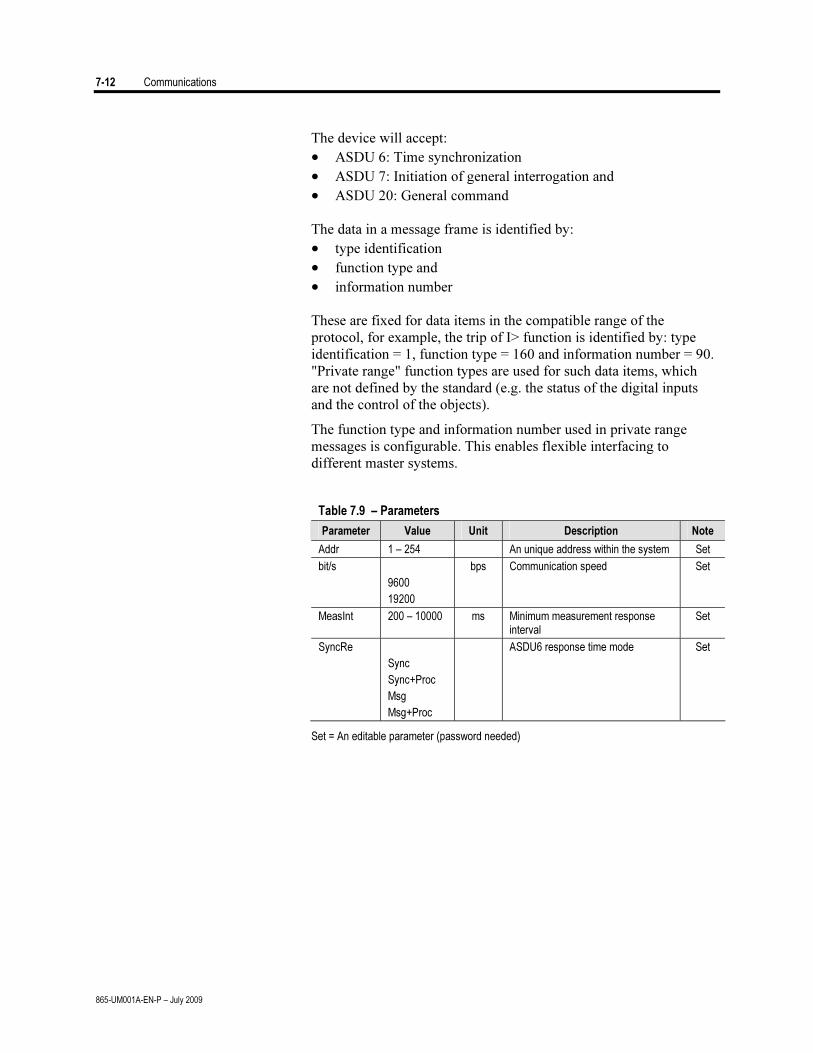
7-12 Communications
865-UM001A-EN-P – July 2009
The device will accept:
• ASDU 6: Time synchronization
• ASDU 7: Initiation of general interrogation and
• ASDU 20: General command
The data in a message frame is identified by:
• type identification
• function type and
• information number
These are fixed for data items in the compatible range of the
protocol, for example, the trip of I> function is identified by: type
identification = 1, function type = 160 and information number = 90.
"Private range" function types are used for such data items, which
are not defined by the standard (e.g. the status of the digital inputs
and the control of the objects).
The function type and information number used in private range
messages is configurable. This enables flexible interfacing to
different master systems.
Table 7.9 – Parameters
Parameter Value Unit Description Note
Addr 1 – 254 An unique address within the system Set
bit/s
9600
19200
bps Communication speed Set
MeasInt 200 – 10000 ms Minimum measurement response interval
Set
SyncRe
Sync
Sync+Proc
Msg
Msg+Proc
ASDU6 response time mode Set
Set = An editable parameter (password needed)
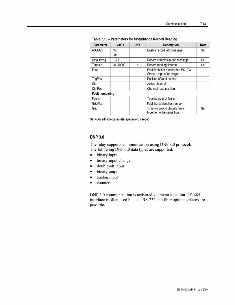
Communications 7-13
865-UM001A-EN-P – July 2009
Table 7.10 – Parameters for Disturbance Record Reading
Parameter Value Unit Description Note
ASDU23 On
Off
Enable record info message Set
Smpls/msg 1–25 Record samples in one message Set
Timeout 10–10000 s Record reading timeout Set
Fault Fault identifier number for IEC-103. Starts + trips of all stages.
TagPos Position of read pointer
Chn Active channel
ChnPos Channel read position
Fault numbering
Faults Total number of faults
GridFlts Fault burst identifier number
Grid Time window to classify faults together to the same burst.
Set
Set = An editable parameter (password needed)
DNP 3.0
The relay supports communication using DNP 3.0 protocol.
The following DNP 3.0 data types are supported:
• binary input
• binary input change
• double-bit input
• binary output
• analog input
• counters
DNP 3.0 communication is activated via menu selection. RS-485
interface is often used but also RS-232 and fiber optic interfaces are
possible.
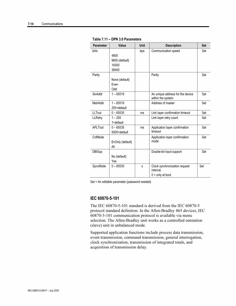
7-14 Communications
865-UM001A-EN-P – July 2009
Table 7.11 – DPN 3.0 Parameters
Parameter Value Unit Description Set
bit/s
4800
9600 (default)
19200
38400
bps Communication speed Set
Parity
None (default)
Even
Odd
Parity Set
SlvAddr 1 – 65519 An unique address for the device within the system
Set
MstrAddr 1 – 65519
255=default
Address of master Set
LLTout 0 – 65535 ms Link layer confirmation timeout Set
LLRetry 1 – 255
1=default
Link layer retry count Set
APLTout 0 – 65535
5000=default
ms Application layer confirmation timeout
Set
CnfMode
EvOnly (default)
All
Application layer confirmation mode
Set
DBISup
No (default)
Yes
Double-bit input support Set
SyncMode 0 – 65535 s Clock synchronization request interval.
0 = only at boot
Set
Set = An editable parameter (password needed)
IEC 60870-5-101
The IEC 60870-5-101 standard is derived from the IEC 60870-5
protocol standard definition. In the Allen-Bradley 865 devices, IEC
60870-5-101 communication protocol is available via menu
selection. The Allen-Bradley unit works as a controlled outstation
(slave) unit in unbalanced mode.
Supported application functions include process data transmission,
event transmission, command transmission, general interrogation,
clock synchronization, transmission of integrated totals, and
acquisition of transmission delay.
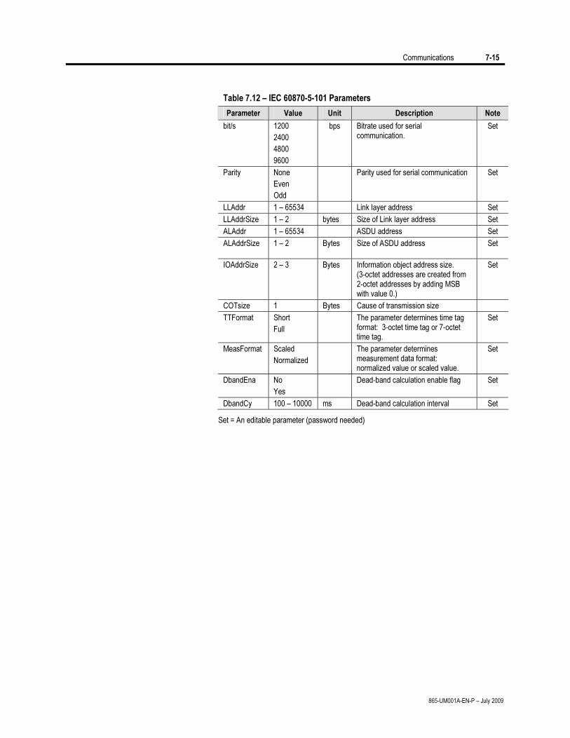
Communications 7-15
865-UM001A-EN-P – July 2009
Table 7.12 – IEC 60870-5-101 Parameters
Parameter Value Unit Description Note
bit/s 1200
2400
4800
9600
bps Bitrate used for serial communication.
Set
Parity None
Even
Odd
Parity used for serial communication Set
LLAddr 1 – 65534 Link layer address Set
LLAddrSize 1 – 2 bytes Size of Link layer address Set
ALAddr 1 – 65534 ASDU address Set
ALAddrSize 1 – 2
Bytes Size of ASDU address Set
IOAddrSize 2 – 3 Bytes Information object address size. (3-octet addresses are created from 2-octet addresses by adding MSB with value 0.)
Set
COTsize 1 Bytes Cause of transmission size
TTFormat Short
Full
The parameter determines time tag format: 3-octet time tag or 7-octet time tag.
Set
MeasFormat Scaled
Normalized
The parameter determines measurement data format: normalized value or scaled value.
Set
DbandEna No
Yes
Dead-band calculation enable flag Set
DbandCy 100 – 10000 ms Dead-band calculation interval Set
Set = An editable parameter (password needed)

7-16 Communications
865-UM001A-EN-P – July 2009
TCP/IP
Modbus TCP uses TCP/IP protocol. Also SetPointPS and SPA-bus
and DNP 3.0 communication can be directed via TCP/IP.
The IP address, net mask, gateway, name server and NTP server are
common with the internal Ethernet port setting.
Table 7.13 – TCP/IP Parameters
Parameter Value Unit Description Set
IpAddr n.n.n.n Internet protocol address (set with SetPointPS)
Set
NetMsk n.n.n.n Net mask (set with SetPointPS) Set
Gatew default = 0.0.0.0 Gateway IP address (set with SetPointPS)
Set
NameSv default = 0.0.0.0 Name server (set with SetPointPS) Set
NTPSvr n.n.n.n Network time protocol server (set with SetPointPS)
0.0.0.0 = no SNTP
Set
Port 502 = default Port 502 is reserved for Modbus TCP
Set
Set = An editable parameter (password needed)
External I/O (Modbus RTU master)
External Modbus I/O devices can be connected to the relay using this
protocol. (See “External input/output Module” in Chapter 9 for more
information).
IEC 61850
IEC 61850 protocol is available with the optional 61850 interface.
The protocol can be configured to transfer the same information
which is available with the IEC 103 protocol. When IEC 61850 is
used, the Remote port protocol of the relay is set to IEC-103.
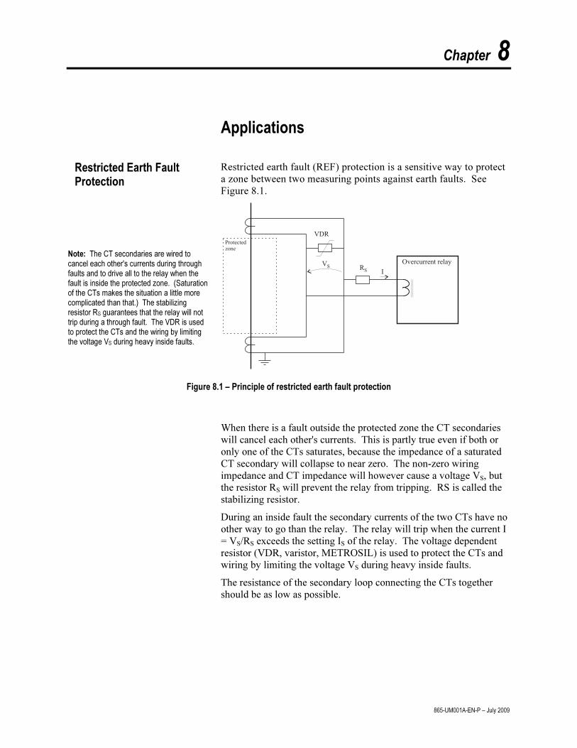
Chapter 8
865-UM001A-EN-P – July 2009
Applications Restricted earth fault (REF) protection is a sensitive way to protect
a zone between two measuring points against earth faults. See Figure 8.1.
Note: The CT secondaries are wired to cancel each other's currents during through faults and to drive all to the relay when the fault is inside the protected zone. (Saturation of the CTs makes the situation a little more complicated than that.) The stabilizing resistor RS guarantees that the relay will not trip during a through fault. The VDR is used to protect the CTs and the wiring by limiting the voltage VS during heavy inside faults.
Figure 8.1 – Principle of restricted earth fault protection
When there is a fault outside the protected zone the CT secondaries
will cancel each other's currents. This is partly true even if both or only one of the CTs saturates, because the impedance of a saturated CT secondary will collapse to near zero. The non-zero wiring impedance and CT impedance will however cause a voltage VS, but the resistor RS will prevent the relay from tripping. RS is called the stabilizing resistor.
During an inside fault the secondary currents of the two CTs have no other way to go than the relay. The relay will trip when the current I = VS/RS exceeds the setting IS of the relay. The voltage dependent resistor (VDR, varistor, METROSIL) is used to protect the CTs and wiring by limiting the voltage VS during heavy inside faults.
The resistance of the secondary loop connecting the CTs together should be as low as possible.
Restricted Earth Fault Protection
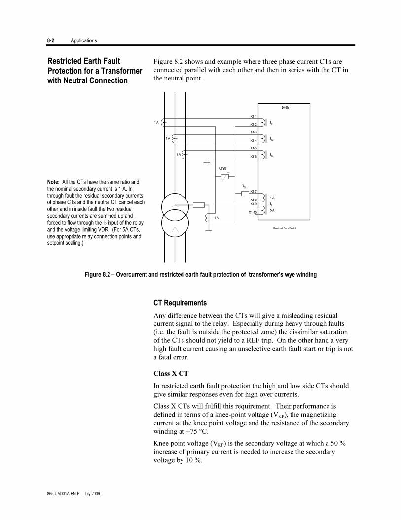
8-2 Applications
865-UM001A-EN-P – July 2009
Figure 8.2 shows and example where three phase current CTs are connected parallel with each other and then in series with the CT in the neutral point.
Note: All the CTs have the same ratio and the nominal secondary current is 1 A. In through fault the residual secondary currents of phase CTs and the neutral CT cancel each other and in inside fault the two residual secondary currents are summed up and forced to flow through the I0 input of the relay and the voltage limiting VDR. (For 5A CTs, use appropriate relay connection points and setpoint scaling.)
RS
VDR
865
IL1
IL2
IL3
1A
1A
1A
1A
1A
5A
I0
X1-1
X1-2
X1-3
X1-4
X1-5
X1-6
X1-7
X1-8
X1-9
X1-10
Restricted Earth Fault 3
Figure 8.2 – Overcurrent and restricted earth fault protection of transformer's wye winding
CT Requirements
Any difference between the CTs will give a misleading residual current signal to the relay. Especially during heavy through faults (i.e. the fault is outside the protected zone) the dissimilar saturation of the CTs should not yield to a REF trip. On the other hand a very high fault current causing an unselective earth fault start or trip is not a fatal error.
Class X CT
In restricted earth fault protection the high and low side CTs should give similar responses even for high over currents.
Class X CTs will fulfill this requirement. Their performance is defined in terms of a knee-point voltage (VKP), the magnetizing current at the knee point voltage and the resistance of the secondary winding at +75 °C.
Knee point voltage (VKP) is the secondary voltage at which a 50 % increase of primary current is needed to increase the secondary voltage by 10 %.
Restricted Earth Fault Protection for a Transformer with Neutral Connection
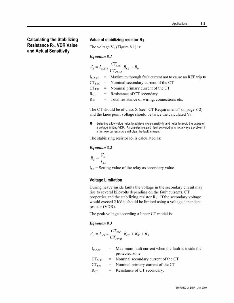
Applications 8-3
865-UM001A-EN-P – July 2009
Value of stabilizing resistor RS
The voltage VS (Figure 8.1) is:
Equation 8.1
WCT
PRIM
SEC
MAXTSRR
CT
CTIV +=
IMAXT = Maximum through fault current not to cause an REF trip CTSEC = Nominal secondary current of the CT CTPRI = Nominal primary current of the CT RCT = Resistance of CT secondary. RW = Total resistance of wiring, connections etc.
The CT should be of class X (see “CT Requirements” on page 8-2)
and the knee point voltage should be twice the calculated VS.
Selecting a low value helps to achieve more sensitivity and helps to avoid the usage of a voltage limiting VDR. An unselective earth fault pick-up/trip is not always a problem if a fast overcurrent stage will clear the fault anyway.
The stabilizing resistor RS is calculated as:
Equation 8.2
R
V
IS
S
Set
=
ISet = Setting value of the relay as secondary value.
Voltage Limitation
During heavy inside faults the voltage in the secondary circuit may rise to several kilovolts depending on the fault currents, CT properties and the stabilizing resistor RS. If the secondary voltage would exceed 2 kV it should be limited using a voltage dependent resistor (VDR).
The peak voltage according a linear CT model is:
Equation 8.3
SWCT
PRIM
SECMAXFp RRB
CT
CTIV ++=
IMAXF = Maximum fault current when the fault is inside the
protected zone CTSEC = Nominal secondary current of the CT CTPRI = Nominal primary current of the CT RCT = Resistance of CT secondary.
Calculating the Stabilizing Resistance RS, VDR Value and Actual Sensitivity
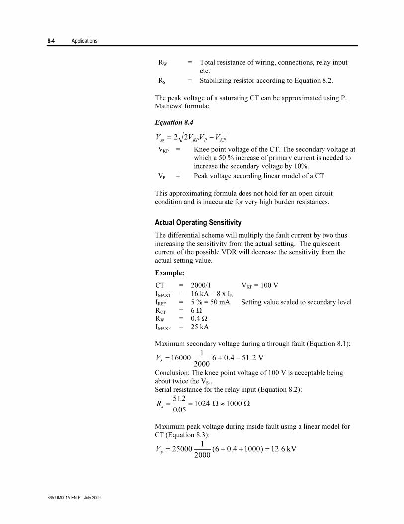
8-4 Applications
865-UM001A-EN-P – July 2009
RW = Total resistance of wiring, connections, relay input
etc. RS = Stabilizing resistor according to Equation 8.2.
The peak voltage of a saturating CT can be approximated using P.
Mathews' formula:
Equation 8.4
KPPKPsp VVVV −= 22
VKP = Knee point voltage of the CT. The secondary voltage at which a 50 % increase of primary current is needed to increase the secondary voltage by 10%.
VP = Peak voltage according linear model of a CT This approximating formula does not hold for an open circuit
condition and is inaccurate for very high burden resistances.
Actual Operating Sensitivity
The differential scheme will multiply the fault current by two thus increasing the sensitivity from the actual setting. The quiescent current of the possible VDR will decrease the sensitivity from the actual setting value.
Example:
CT = 2000/1 VKP = 100 V IMAXT = 16 kA = 8 x IN IREF = 5 % = 50 mA Setting value scaled to secondary level RCT = 6 Ω RW = 0.4 Ω IMAXF = 25 kA
Maximum secondary voltage during a through fault (Equation 8.1):
V 2.514.062000
116000 −+=
SV
Conclusion: The knee point voltage of 100 V is acceptable being about twice the VS..
Serial resistance for the relay input (Equation 8.2):
R
S= = ≈
512
0 051024 1000
.
. Ω Ω
Maximum peak voltage during inside fault using a linear model for
CT (Equation 8.3):
kV 6.12)10004.06(2000
125000 =++=
pV
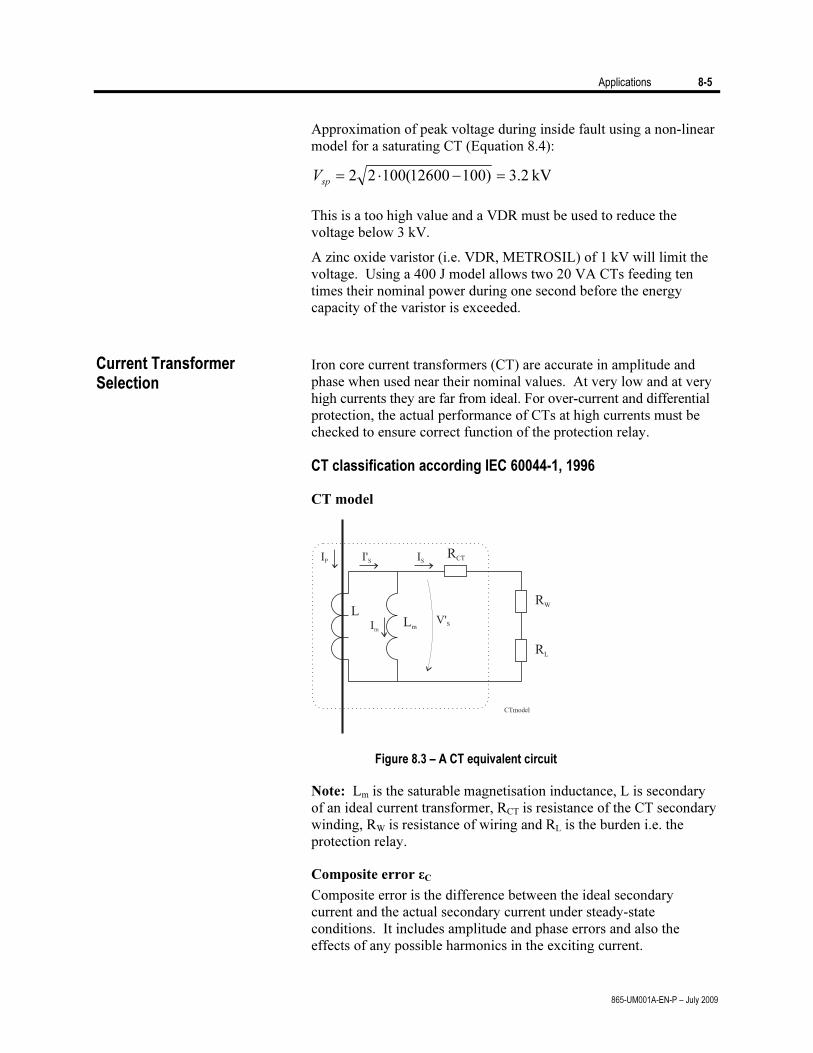
Applications 8-5
865-UM001A-EN-P – July 2009
Approximation of peak voltage during inside fault using a non-linear model for a saturating CT (Equation 8.4):
kV 2.3)10012600(10022 =−⋅=sp
V
This is a too high value and a VDR must be used to reduce the
voltage below 3 kV.
A zinc oxide varistor (i.e. VDR, METROSIL) of 1 kV will limit the voltage. Using a 400 J model allows two 20 VA CTs feeding ten times their nominal power during one second before the energy capacity of the varistor is exceeded.
Iron core current transformers (CT) are accurate in amplitude and
phase when used near their nominal values. At very low and at very high currents they are far from ideal. For over-current and differential protection, the actual performance of CTs at high currents must be checked to ensure correct function of the protection relay.
CT classification according IEC 60044-1, 1996
CT model
Figure 8.3 – A CT equivalent circuit
Note: Lm is the saturable magnetisation inductance, L is secondary of an ideal current transformer, RCT is resistance of the CT secondary winding, RW is resistance of wiring and RL is the burden i.e. the protection relay.
Composite error εC
Composite error is the difference between the ideal secondary current and the actual secondary current under steady-state conditions. It includes amplitude and phase errors and also the effects of any possible harmonics in the exciting current.
Current Transformer Selection
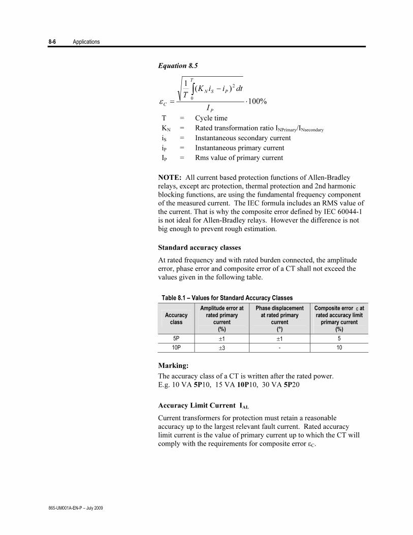
8-6 Applications
865-UM001A-EN-P – July 2009
Equation 8.5
%100
)(1 2
0
⋅
−
=
∫
P
T
PSN
C
I
dtiiKT
ε
T = Cycle time KN = Rated transformation ratio INPrimary/INsecondary
iS = Instantaneous secondary current iP = Instantaneous primary current IP = Rms value of primary current
NOTE: All current based protection functions of Allen-Bradley relays, except arc protection, thermal protection and 2nd harmonic blocking functions, are using the fundamental frequency component of the measured current. The IEC formula includes an RMS value of the current. That is why the composite error defined by IEC 60044-1 is not ideal for Allen-Bradley relays. However the difference is not big enough to prevent rough estimation.
Standard accuracy classes
At rated frequency and with rated burden connected, the amplitude error, phase error and composite error of a CT shall not exceed the values given in the following table.
Table 8.1 – Values for Standard Accuracy Classes
Accuracy class
Amplitude error at rated primary
current
(%)
Phase displacement at rated primary
current (°)
Composite error C at rated accuracy limit
primary current (%)
5P ±1 ±1 5
10P ±3 - 10
Marking:
The accuracy class of a CT is written after the rated power. E.g. 10 VA 5P10, 15 VA 10P10, 30 VA 5P20
Accuracy Limit Current IAL
Current transformers for protection must retain a reasonable accuracy up to the largest relevant fault current. Rated accuracy limit current is the value of primary current up to which the CT will comply with the requirements for composite error εC.
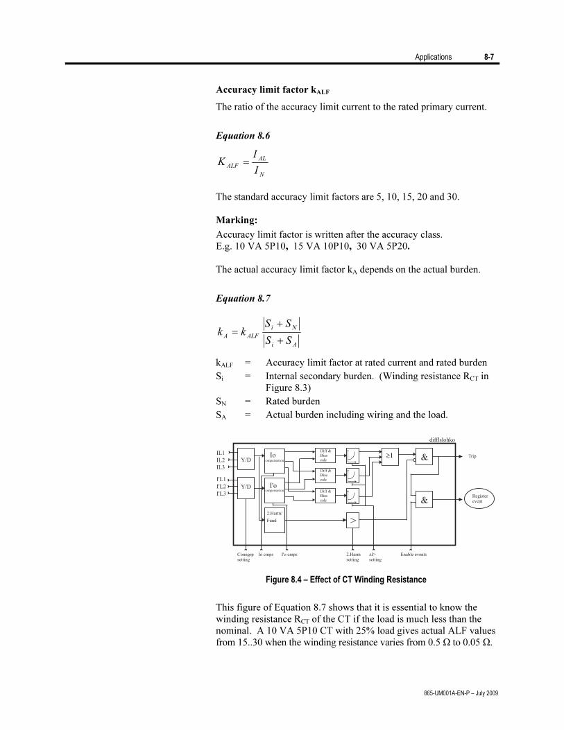
Applications 8-7
865-UM001A-EN-P – July 2009
Accuracy limit factor kALF
The ratio of the accuracy limit current to the rated primary current.
Equation 8.6
N
AL
ALF
I
IK =
The standard accuracy limit factors are 5, 10, 15, 20 and 30. Marking:
Accuracy limit factor is written after the accuracy class. E.g. 10 VA 5P10, 15 VA 10P10, 30 VA 5P20. The actual accuracy limit factor kA depends on the actual burden.
Equation 8.7
Ai
Ni
ALFA
SS
SSkk
+
+
=
kALF = Accuracy limit factor at rated current and rated burden Si = Internal secondary burden. (Winding resistance RCT in
Figure 8.3) SN = Rated burden SA = Actual burden including wiring and the load.
Figure 8.4 – Effect of CT Winding Resistance
This figure of Equation 8.7 shows that it is essential to know the winding resistance RCT of the CT if the load is much less than the nominal. A 10 VA 5P10 CT with 25% load gives actual ALF values from 15..30 when the winding resistance varies from 0.5 Ω to 0.05 Ω.
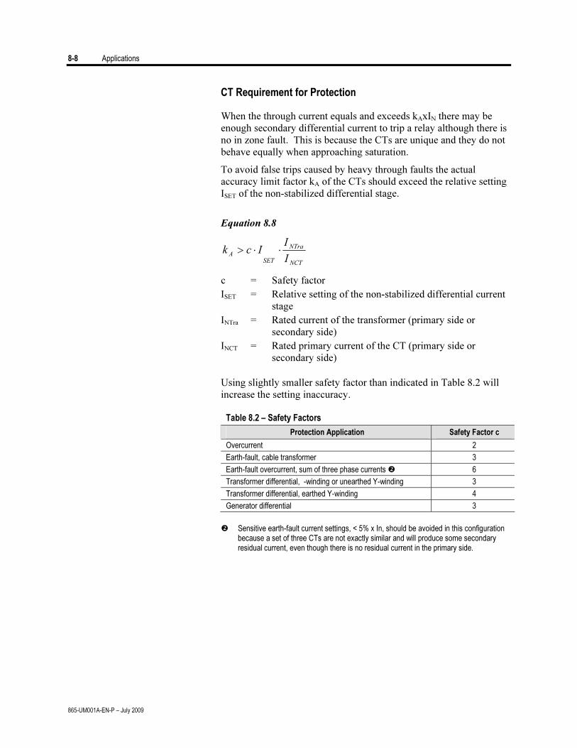
8-8 Applications
865-UM001A-EN-P – July 2009
CT Requirement for Protection
When the through current equals and exceeds kAxIN there may be enough secondary differential current to trip a relay although there is no in zone fault. This is because the CTs are unique and they do not behave equally when approaching saturation.
To avoid false trips caused by heavy through faults the actual accuracy limit factor kA of the CTs should exceed the relative setting ISET of the non-stabilized differential stage.
Equation 8.8
NCT
NTra
SET
A
I
IIck ⋅⋅>
c = Safety factor ISET = Relative setting of the non-stabilized differential current
stage INTra = Rated current of the transformer (primary side or
secondary side) INCT = Rated primary current of the CT (primary side or
secondary side) Using slightly smaller safety factor than indicated in Table 8.2 will
increase the setting inaccuracy.
Table 8.2 – Safety Factors
Protection Application Safety Factor c
Overcurrent 2
Earth-fault, cable transformer 3
Earth-fault overcurrent, sum of three phase currents 6
Transformer differential, -winding or unearthed Y-winding 3
Transformer differential, earthed Y-winding 4
Generator differential 3
Sensitive earth-fault current settings, < 5% x In, should be avoided in this configuration because a set of three CTs are not exactly similar and will produce some secondary residual current, even though there is no residual current in the primary side.
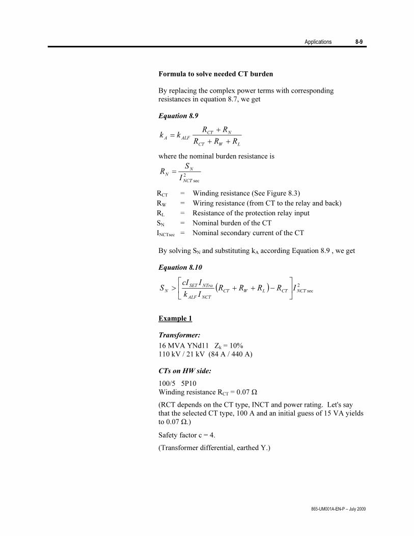
Applications 8-9
865-UM001A-EN-P – July 2009
Formula to solve needed CT burden
By replacing the complex power terms with corresponding resistances in equation 8.7, we get
Equation 8.9
LWCT
NCT
ALFA
RRR
RRkk
++
+
=
where the nominal burden resistance is
2
secNCT
N
N
I
SR =
RCT = Winding resistance (See Figure 8.3) RW = Wiring resistance (from CT to the relay and back) RL = Resistance of the protection relay input SN = Nominal burden of the CT INCTsec = Nominal secondary current of the CT
By solving SN and substituting kA according Equation 8.9 , we get
Equation 8.10
( ) 2
secNCTCTLWCT
NCTALF
NTraSET
NIRRRR
Ik
IcIS ⎥
⎦
⎤⎢⎣
⎡−++>
Example 1
Transformer:
16 MVA YNd11 Zk = 10% 110 kV / 21 kV (84 A / 440 A)
CTs on HW side:
100/5 5P10 Winding resistance RCT = 0.07 Ω
(RCT depends on the CT type, INCT and power rating. Let's say that the selected CT type, 100 A and an initial guess of 15 VA yields to 0.07 Ω.)
Safety factor c = 4.
(Transformer differential, earthed Y.)
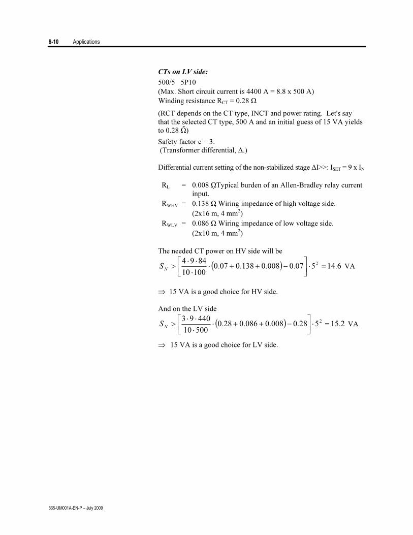
8-10 Applications
865-UM001A-EN-P – July 2009
CTs on LV side:
500/5 5P10 (Max. Short circuit current is 4400 A = 8.8 x 500 A) Winding resistance RCT = 0.28 Ω
(RCT depends on the CT type, INCT and power rating. Let's say that the selected CT type, 500 A and an initial guess of 15 VA yields to 0.28 Ω)
Safety factor c = 3. (Transformer differential, Δ.) Differential current setting of the non-stabilized stage ΔI>>: ISET = 9 x IN
RL = 0.008 ΩTypical burden of an Allen-Bradley relay current input.
RWHV = 0.138 Ω Wiring impedance of high voltage side. (2x16 m, 4 mm2)
RWLV = 0.086 Ω Wiring impedance of low voltage side. (2x10 m, 4 mm2)
The needed CT power on HV side will be
( ) 6.14507.0008.0138.007.010010
8494 2 =⋅⎥⎦
⎤⎢⎣
⎡−++⋅
⋅
⋅⋅>
NS VA
⇒ 15 VA is a good choice for HV side. And on the LV side
( ) 2.15528.0008.0086.028.050010
44093 2 =⋅⎥⎦
⎤⎢⎣
⎡−++⋅
⋅
⋅⋅>
NS VA
⇒ 15 VA is a good choice for LV side.
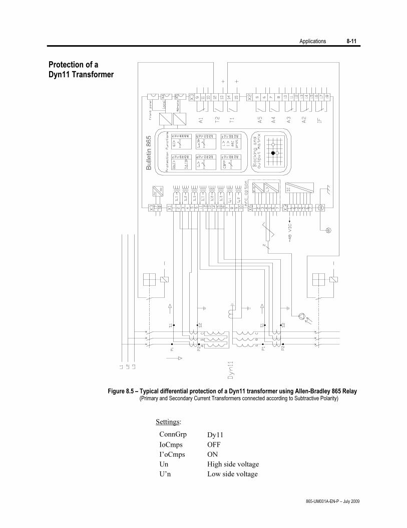
Applications 8-11
865-UM001A-EN-P – July 2009
Bulle
tin 8
65
Figure 8.5 – Typical differential protection of a Dyn11 transformer using Allen-Bradley 865 Relay (Primary and Secondary Current Transformers connected according to Subtractive Polarity)
Settings:
ConnGrp Dy11 IoCmps OFF I’oCmps ON Un High side voltage U’n Low side voltage
Protection of a Dyn11 Transformer
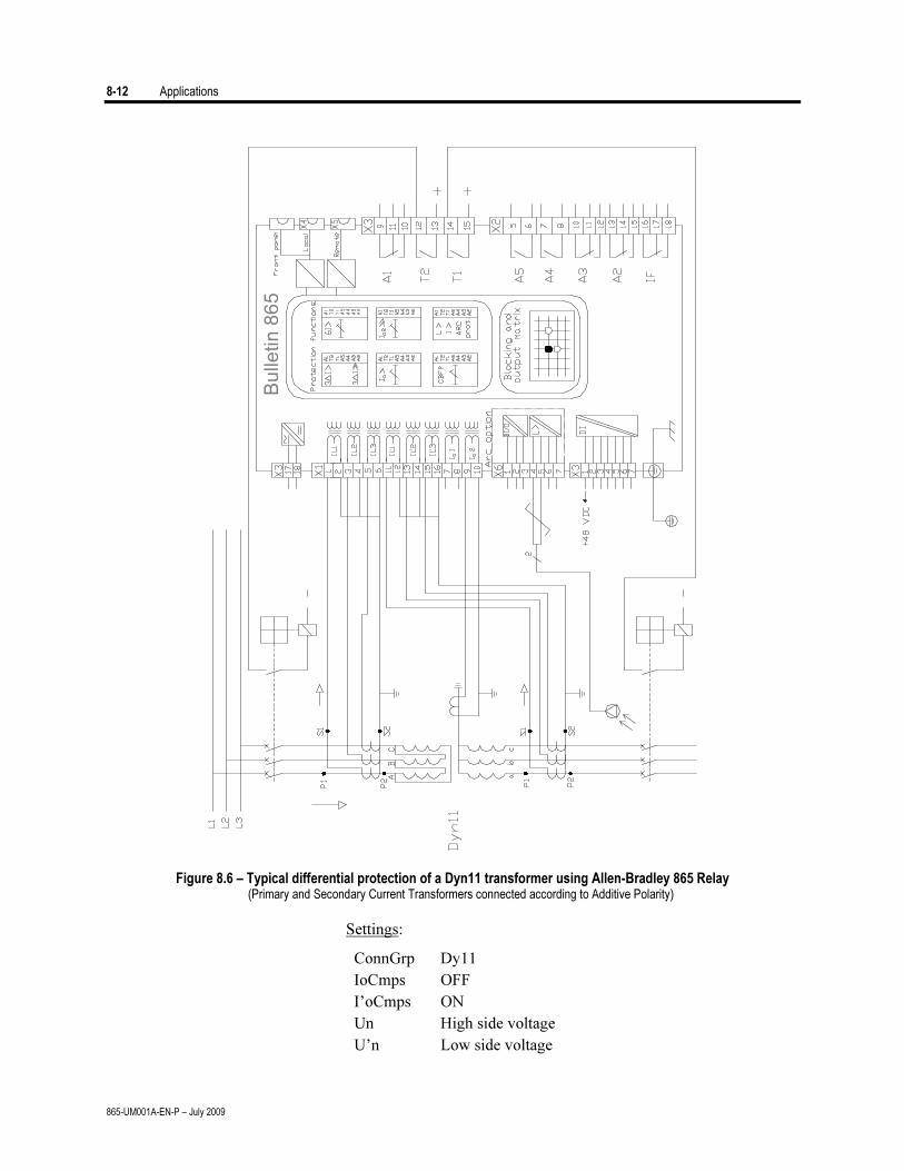
8-12 Applications
865-UM001A-EN-P – July 2009
Bu
lle
tin
86
5
Figure 8.6 – Typical differential protection of a Dyn11 transformer using Allen-Bradley 865 Relay
(Primary and Secondary Current Transformers connected according to Additive Polarity)
Settings:
ConnGrp Dy11 IoCmps OFF I’oCmps ON Un High side voltage U’n Low side voltage
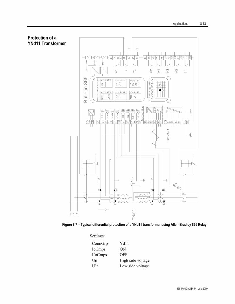
Applications 8-13
865-UM001A-EN-P – July 2009
Bu
lle
tin
86
5
Figure 8.7 – Typical differential protection of a YNd11 transformer using Allen-Bradley 865 Relay
Settings:
ConnGrp Yd11 IoCmps ON I’oCmps OFF Un High side voltage U’n Low side voltage
Protection of a YNd11 Transformer
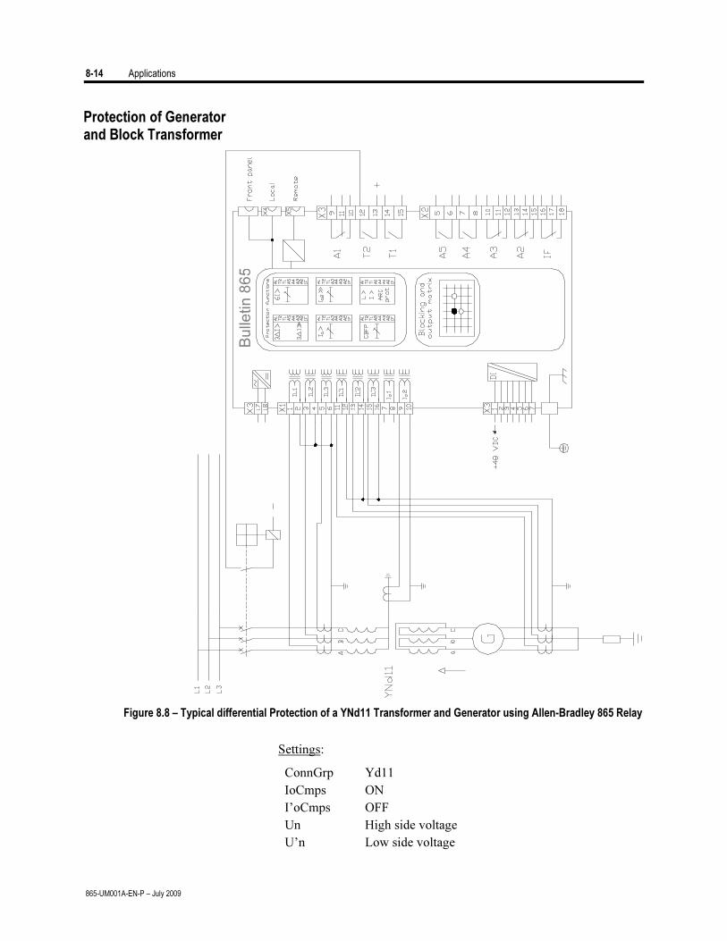
8-14 Applications
865-UM001A-EN-P – July 2009
Bu
lle
tin
86
5
Figure 8.8 – Typical differential Protection of a YNd11 Transformer and Generator using Allen-Bradley 865 Relay
Settings:
ConnGrp Yd11 IoCmps ON I’oCmps OFF Un High side voltage U’n Low side voltage
Protection of Generator and Block Transformer
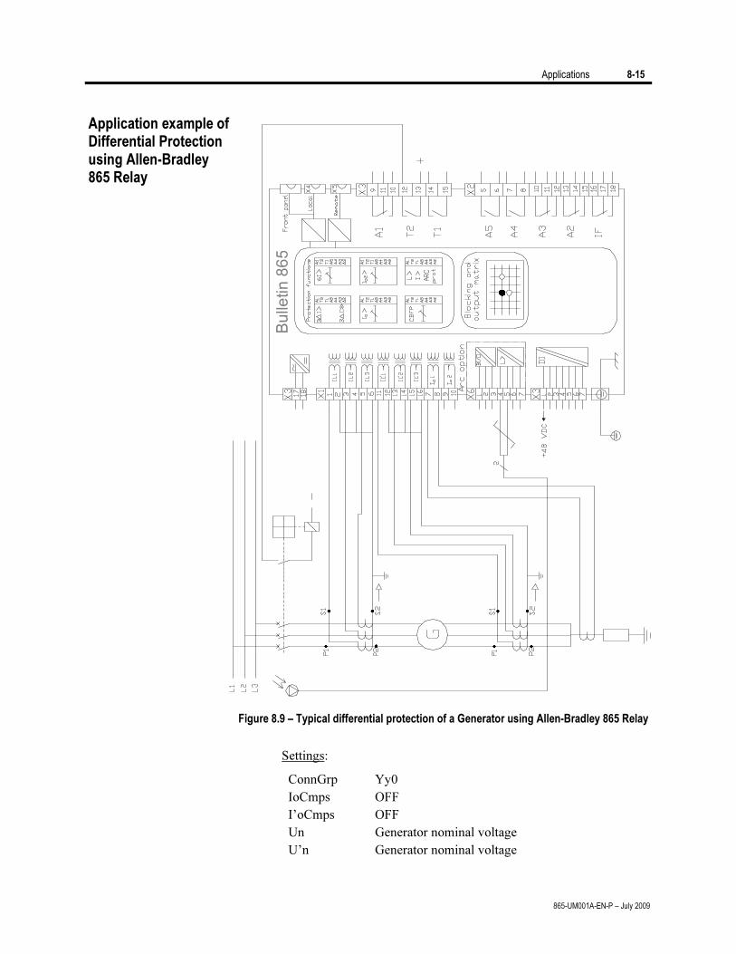
Applications 8-15
865-UM001A-EN-P – July 2009
Bu
lle
tin
86
5
Figure 8.9 – Typical differential protection of a Generator using Allen-Bradley 865 Relay
Settings:
ConnGrp Yy0 IoCmps OFF I’oCmps OFF Un Generator nominal voltage U’n Generator nominal voltage
Application example of Differential Protection using Allen-Bradley 865 Relay
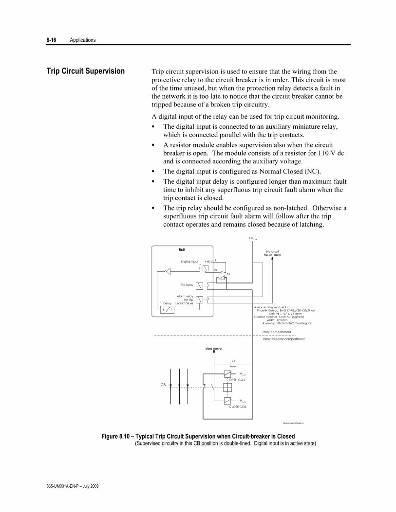
8-16 Applications
865-UM001A-EN-P – July 2009
Trip Circuit Supervision Trip circuit supervision is used to ensure that the wiring from the protective relay to the circuit breaker is in order. This circuit is most of the time unused, but when the protection relay detects a fault in the network it is too late to notice that the circuit breaker cannot be tripped because of a broken trip circuitry.
A digital input of the relay can be used for trip circuit monitoring.
The digital input is connected to an auxiliary miniature relay, which is connected parallel with the trip contacts.
A resistor module enables supervision also when the circuit breaker is open. The module consists of a resistor for 110 V dc and is connected according the auxiliary voltage.
The digital input is configured as Normal Closed (NC).
The digital input delay is configured longer than maximum fault time to inhibit any superfluous trip circuit fault alarm when the trip contact is closed.
The trip relay should be configured as non-latched. Otherwise a superfluous trip circuit fault alarm will follow after the trip contact operates and remains closed because of latching.
CB
CLOSE COIL
OPEN COIL
close control
trip circuit
failure alarm
R1
-VAUX
+VAUX
-VAUX
865
Digital input
Trip relay
Delay
Alarm relayfor trip
circuit failure
relay compartment
circuit breaker compartment
+
K1
1
DI
+48 V
A snap in relay module K1:
Phoenix Contact EMG 17-REL/KSR-120/21 AuCoil: 96 .. 127 V, 24 kohm
Contact material: 5 mm Au (AgPd60)
Width: 17.5 mmAssembly: DIN EN 50022 mounting rail
TripCircuitSup200CloseP os
Figure 8.10 – Typical Trip Circuit Supervision when Circuit-breaker is Closed (Supervised circuitry in this CB position is double-lined. Digital input is in active state)
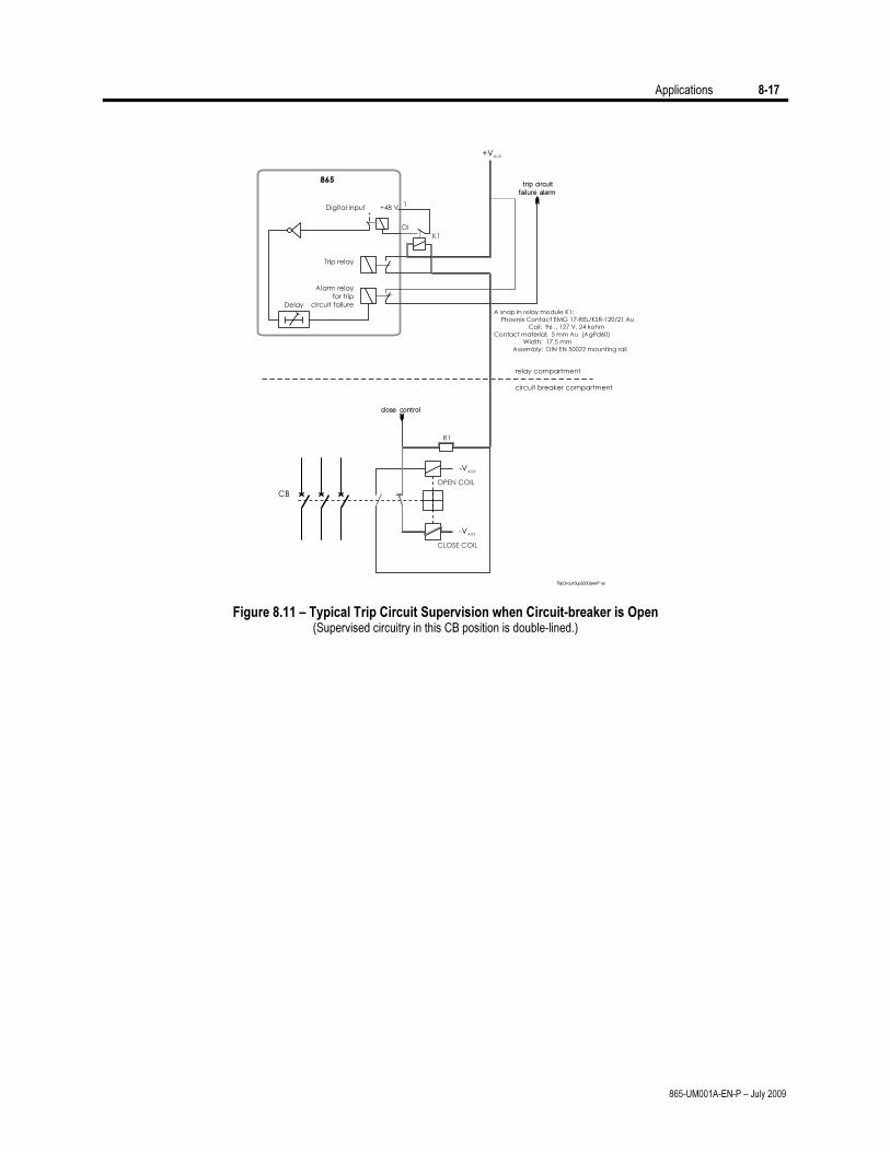
Applications 8-17
865-UM001A-EN-P – July 2009
CB
CLOSE COIL
OPEN COIL
-VAUX
-VAUX
Delay
Alarm relay
for trip
circuit failure
close control
trip circuit
failure alarm
R1
+VAUX
865
Digital input
Trip relay
relay compartment
circuit breaker compartment
+
K1
1
DI
+48 V
A snap in relay module K1:
Phoenix Contact EMG 17-REL/KSR-120/21 Au
Coil: 96 .. 127 V, 24 kohm
Contact material: 5 mm Au (AgPd60)
Width: 17.5 mm
Assembly: DIN EN 50022 mounting rail
TripCircuitSup200OpenP os
Figure 8.11 – Typical Trip Circuit Supervision when Circuit-breaker is Open (Supervised circuitry in this CB position is double-lined.)

8-18 Applications
865-UM001A-EN-P – July 2009
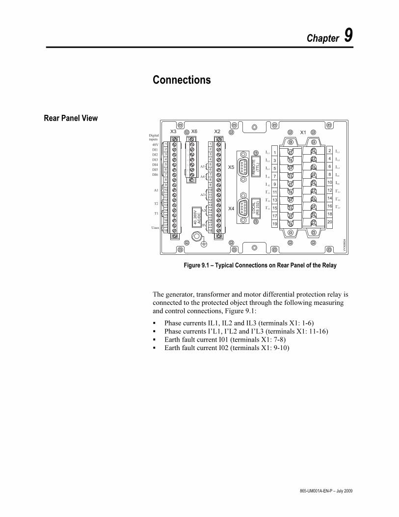
Chapter 9
865-UM001A-EN-P – July 2009
Connections
1
2
3
4
5
6
7
8
9
10
11
12
13
14
15
16
17
18
1
2
3
4
5
6
7
8
9
10
11
12
13
14
15
16
17
18
1
3
5
7
9
11
13
15
17
19
2
4
6
8
10
12
14
16
18
20
X3 X6 X1
VY
X0
60
A
40..265V
AC
/DC
LO
CA
L(R
S232)
RE
MO
TE
(TT
L)
Digitalinputs
48V
DI1
DI2
DI3
DI4
DI5
DI6
A1
A5
A4
A3
A2
IF
T1
Uaux
T2
I´
I
I´
I
I
I I
I
I I
I I
I´ I´
I´ I´
L1L1
L3
0101
0202
L3
L2L2
L1L1
L2L2
L3L3
1
2
3
4
5
6
7
X5
X4
X2
Figure 9.1 – Typical Connections on Rear Panel of the Relay
The generator, transformer and motor differential protection relay is
connected to the protected object through the following measuring and control connections, Figure 9.1:
Phase currents IL1, IL2 and IL3 (terminals X1: 1-6) Phase currents I’L1, I’L2 and I’L3 (terminals X1: 11-16) Earth fault current I01 (terminals X1: 7-8) Earth fault current I02 (terminals X1: 9-10)
Rear Panel View
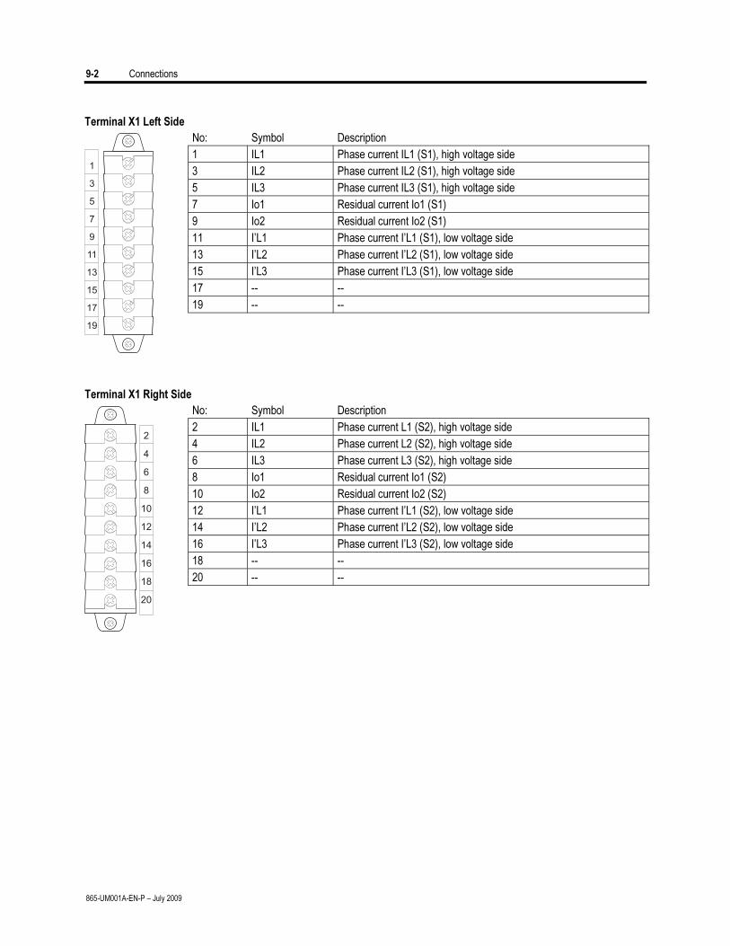
9-2 Connections
865-UM001A-EN-P – July 2009
Terminal X1 Left Side
No: Symbol Description
1 IL1 Phase current IL1 (S1), high voltage side
3 IL2 Phase current IL2 (S1), high voltage side
5 IL3 Phase current IL3 (S1), high voltage side
7 Io1 Residual current Io1 (S1)
9 Io2 Residual current Io2 (S1)
11 I’L1 Phase current I’L1 (S1), low voltage side
13 I’L2 Phase current I’L2 (S1), low voltage side
15 I’L3 Phase current I’L3 (S1), low voltage side
17 -- --
19 -- --
Terminal X1 Right Side
No: Symbol Description
2 IL1 Phase current L1 (S2), high voltage side
4 IL2 Phase current L2 (S2), high voltage side
6 IL3 Phase current L3 (S2), high voltage side
8 Io1 Residual current Io1 (S2)
10 Io2 Residual current Io2 (S2)
12 I’L1 Phase current I’L1 (S2), low voltage side
14 I’L2 Phase current I’L2 (S2), low voltage side
16 I’L3 Phase current I’L3 (S2), low voltage side
18 -- --
20 -- --
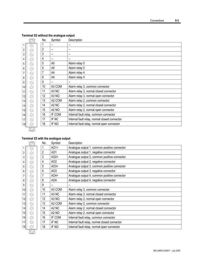
Connections 9-3
865-UM001A-EN-P – July 2009
Terminal X2 without the analogue output
No: Symbol Description
1 -- --
2 -- --
3 -- --
4 -- --
5 A5 Alarm relay 5
6 A5 Alarm relay 5
7 A4 Alarm relay 4
8 A4 Alarm relay 4
9 -- --
10 A3 COM Alarm relay 3, common connector
11 A3 NC Alarm relay 3, normal closed connector
12 A3 NO Alarm relay 3, normal open connector
13 A2 COM Alarm relay 2, common connector
14 A2 NC Alarm relay 2, normal closed connector
15 A2 NO Alarm relay 2, normal open connector
16 IF COM Internal fault relay, common connector
17 IF NC Internal fault relay, normal closed connector
18 IF NO Internal fault relay, normal open connector
Terminal X2 with the analogue output
No: Symbol Description
1 AO1+ Analogue output 1, common positive connector
2 AO1 Analogue output 1, negative connector
3 AO2+ Analogue output 2, common positive connector
4 AO2 Analogue output 2, negative connector
5 AO3+ Analogue output 3, common positive connector
6 AO3 Analogue output 3, negative connector
7 AO4+ Analogue output 4, common positive connector
8 AO4 Analogue output 4, negative connector
9 -- --
10 A3 COM Alarm relay 3, common connector
11 A3 NC Alarm relay 3, normal closed connector
12 A3 NO Alarm relay 3, normal open connector
13 A2 COM Alarm relay 2, common connector
14 A2 NC Alarm relay 2, normal closed connector
15 A2 NO Alarm relay 2, normal open connector
16 IF COM Internal fault relay, common connector
17 IF NC Internal fault relay, normal closed connector
18 IF NO Internal fault relay, normal open connector
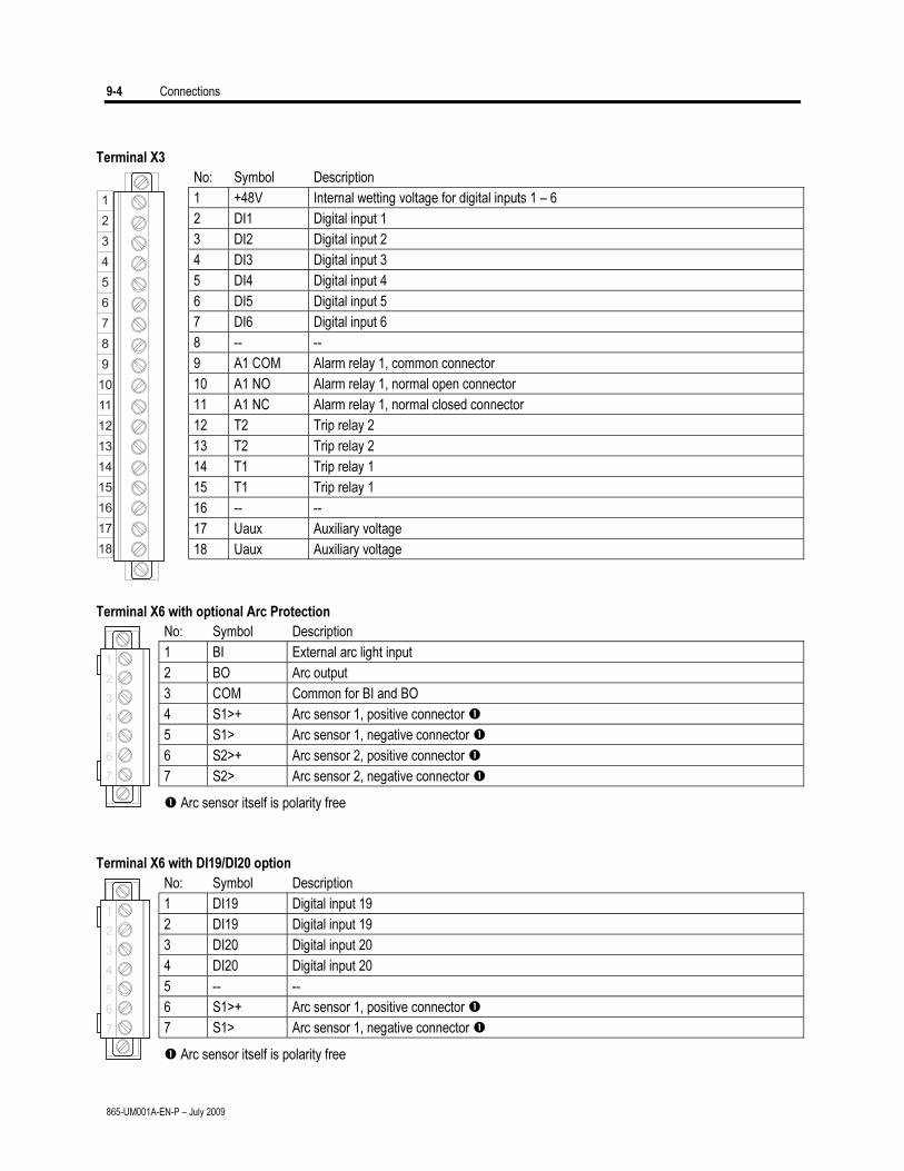
9-4 Connections
865-UM001A-EN-P – July 2009
Terminal X3
No: Symbol Description
1 +48V Internal wetting voltage for digital inputs 1 – 6
2 DI1 Digital input 1
3 DI2 Digital input 2
4 DI3 Digital input 3
5 DI4 Digital input 4
6 DI5 Digital input 5
7 DI6 Digital input 6
8 -- --
9 A1 COM Alarm relay 1, common connector
10 A1 NO Alarm relay 1, normal open connector
11 A1 NC Alarm relay 1, normal closed connector
12 T2 Trip relay 2
13 T2 Trip relay 2
14 T1 Trip relay 1
15 T1 Trip relay 1
16 -- --
17 Uaux Auxiliary voltage
18 Uaux Auxiliary voltage
Terminal X6 with optional Arc Protection
No: Symbol Description
1 BI External arc light input
2 BO Arc output
3 COM Common for BI and BO
4 S1>+ Arc sensor 1, positive connector
5 S1> Arc sensor 1, negative connector
6 S2>+ Arc sensor 2, positive connector
7 S2> Arc sensor 2, negative connector
Arc sensor itself is polarity free
Terminal X6 with DI19/DI20 option
No: Symbol Description
1 DI19 Digital input 19
2 DI19 Digital input 19
3 DI20 Digital input 20
4 DI20 Digital input 20
5 -- --
6 S1>+ Arc sensor 1, positive connector
7 S1> Arc sensor 1, negative connector
Arc sensor itself is polarity free
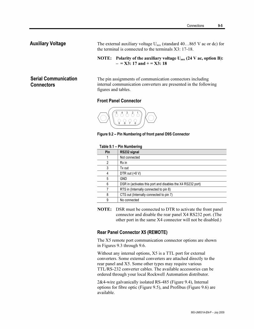
Connections 9-5
865-UM001A-EN-P – July 2009
Auxiliary Voltage The external auxiliary voltage Uaux (standard 40…865 V ac or dc) for the terminal is connected to the terminals X3: 17-18.
NOTE: Polarity of the auxiliary voltage Uaux (24 V ac, option B):
– = X3: 17 and + = X3: 18
The pin assignments of communication connectors including
internal communication converters are presented in the following figures and tables.
Front Panel Connector
Figure 9.2 – Pin Numbering of front panel D9S Connector
Table 9.1 – Pin Numbering
Pin RS232 signal
1 Not connected
2 Rx in
3 Tx out
4 DTR out (+8 V)
5 GND
6 DSR in (activates this port and disables the X4 RS232 port)
7 RTS in (Internally connected to pin 8)
8 CTS out (Internally connected to pin 7)
9 No connected
NOTE: DSR must be connected to DTR to activate the front panel connector and disable the rear panel X4 RS232 port. (The other port in the same X4 connector will not be disabled.)
Rear Panel Connector X5 (REMOTE)
The X5 remote port communication connector options are shown in Figures 9.3 through 9.6.
Without any internal options, X5 is a TTL port for external converters. Some external converters are attached directly to the rear panel and X5. Some other types may require various TTL/RS-232 converter cables. The available accessories can be ordered through your local Rockwell Automation distributor.
2&4-wire galvanically isolated RS-485 (Figure 9.4), Internal options for fibre optic (Figure 9.5), and Profibus (Figure 9.6) are available.
Serial Communication Connectors
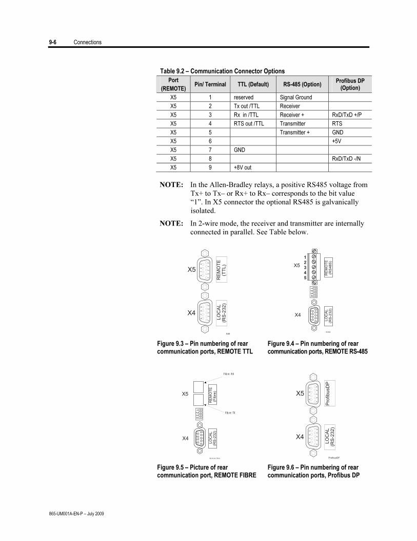
9-6 Connections
865-UM001A-EN-P – July 2009
Table 9.2 – Communication Connector Options
Port
(REMOTE) Pin/ Terminal TTL (Default) RS-485 (Option)
Profibus DP (Option)
X5 1 reserved Signal Ground
X5 2 Tx out /TTL Receiver
X5 3 Rx in /TTL Receiver + RxD/TxD +/P
X5 4 RTS out /TTL Transmitter RTS
X5 5 Transmitter + GND
X5 6 +5V
X5 7 GND
X5 8 RxD/TxD -/N
X5 9 +8V out
NOTE: In the Allen-Bradley relays, a positive RS485 voltage from Tx+ to Tx– or Rx+ to Rx– corresponds to the bit value “1”. In X5 connector the optional RS485 is galvanically isolated.
NOTE: In 2-wire mode, the receiver and transmitter are internally connected in parallel. See Table below.
LO
CA
L(R
S-2
32
)
X4
12
34
5
67
89
X5
RE
MO
TE
(TT
L)
67
89
12
34
5
X45
LO
CA
L(R
S-2
32)
RE
MO
TE
(RS
485)
12
34
5
67
89
12
34
1
2
3
4
5
X5
X4
RS485
Figure 9.3 – Pin numbering of rear communication ports, REMOTE TTL
Figure 9.4 – Pin numbering of rear communication ports, REMOTE RS-485
12
34
5
67
89
LO
CA
L(R
S-2
32)
RE
MO
TE
(Fib
re)
12
34
Fibre RX
Fibre TX
Remote fibre
X5
X4
LO
CA
L(R
S-2
32)
X4
12
34
5
67
89
X5
Pro
fibusD
P
67
89
12
34
5
ProfibusDP
Figure 9.5 – Picture of rear communication port, REMOTE FIBRE
Figure 9.6 – Pin numbering of rear communication ports, Profibus DP
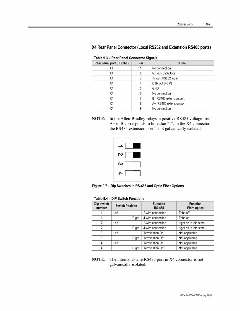
Connections 9-7
865-UM001A-EN-P – July 2009
X4 Rear Panel Connector (Local RS232 and Extension RS485 ports)
Table 9.3 – Rear Panel Connector Signals
Rear panel port (LOCAL) Pin Signal
X4 1 No connection
X4 2 Rx in, RS232 local
X4 3 Tx out, RS232 local
X4 4 DTR out (+8 V)
X4 5 GND
X4 6 No connection
X4 7 B RS485 extension port
X4 8 A+ RS485 extension port
X4 9 No connection
NOTE: In the Allen-Bradley relays, a positive RS485 voltage from A+ to B corresponds to bit value “1”. In the X4 connector the RS485 extension port is not galvanically isolated.
1 2
3 4
Figure 9.7 – Dip Switches in RS-485 and Optic Fiber Options
Table 9.4 – DIP Switch Functions
Dip switch number
Switch Position Function RS-485
Function Fibre optics
1 Left 2-wire connection Echo off
1 Right 4-wire connection Echo on
2 Left 2-wire connection Light on in idle state
2 Right 4-wire connection Light off in idle state
3 Left Termination On Not applicable
3 Right Termination Off Not applicable
4 Left Termination On Not applicable
4 Right Termination Off Not applicable
NOTE: The internal 2-wire RS485 port in X4 connector is not galvanically isolated.
9-8 Connections
865-UM001A-EN-P – July 2009
NOTE: When this option card is installed, the parameter "Arc card type" has value "2Arc+BI/O".
NOTE: If the slot X6 is already occupied with the DI19/DI20 digital input card, this option is not available, but there is still one arc sensor channel available. (See ‘Optional Digital I/O Card – DI19/DI20’ below.)
The optional arc protection card includes two arc sensor channels. The arc sensors are connected to terminals X6: 4-5 and 6-7.
The arc information can be transmitted and/or received through digital input and output channels. This is a 48 V dc signal.
Connections:
X6: 1 Binary input (BI) X6: 2 Binary output (BO) X6: 3 Common for BI and BO. X6: 4-5 Sensor 1 X6: 6-7 Sensor 2
The binary output of the arc option card may be activated by the arc sensors or by any available signal in the output matrix. The binary output can be connected to an arc binary input of another Allen-Bradley protection relay or manager.
NOTE: When this option card is installed, the parameter "Arc card type" has value "Arc+2DI". With DI19/DI20 option only one arc sensor channel is available.
NOTE: If the slot X6 is already occupied with the two-channel arc sensor card, this option is not available.
The DI19/DI20 option enables two more digital inputs. These inputs are useful in applications where the contact signals are not potential free. For example trip circuit supervision is such application. The inputs are connected to terminals X6:1 – X6:2 and X6:3 – X6:4.
Connections:
1 DI19+ X6:2 DI19- X6:3 DI20+ X6:4 DI20- X6:5 NC X6:6 L+ X6:7 L-
Optional Two-Channel Arc Protection Card
Optional Digital I/O Card (DI19/DI20)
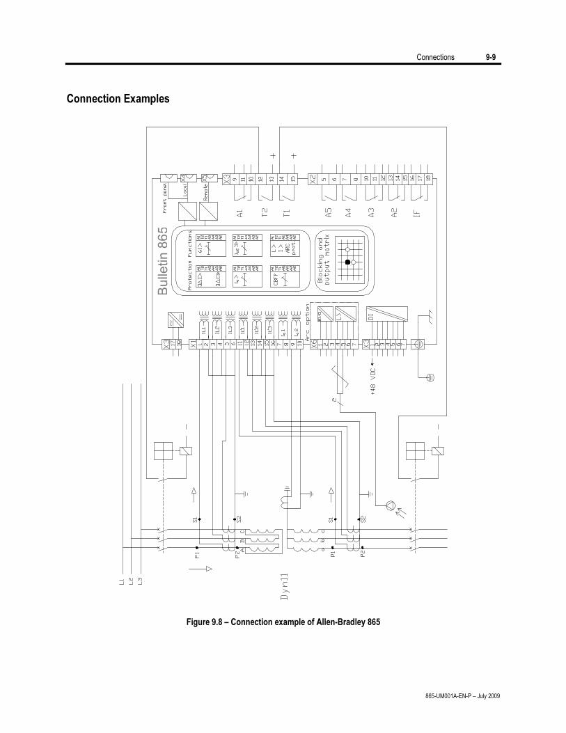
Connections 9-9
865-UM001A-EN-P – July 2009
Connection Examples
Bu
lle
tin
86
5
Figure 9.8 – Connection example of Allen-Bradley 865
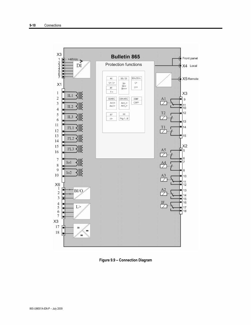
9-10 Connections
865-UM001A-EN-P – July 2009
Figure 9.9 – Connection Diagram
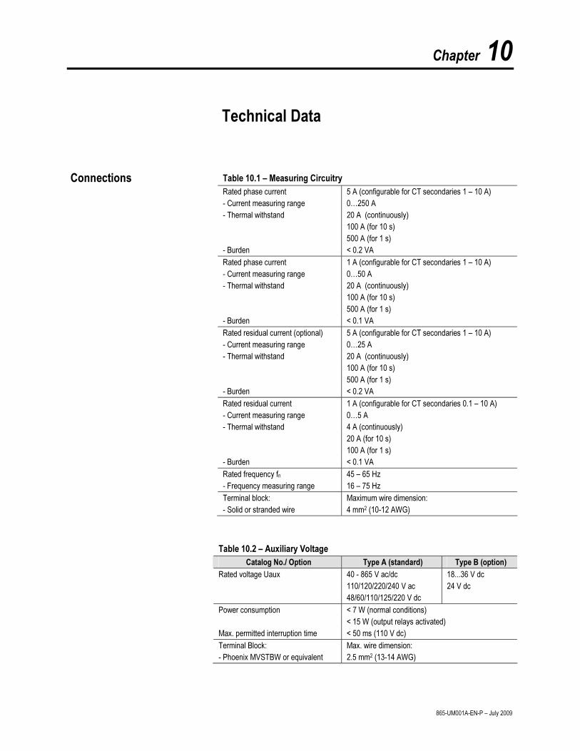
Chapter 10
865-UM001A-EN-P – July 2009
Technical Data
Table 10.1 – Measuring Circuitry
Rated phase current 5 A (configurable for CT secondaries 1 – 10 A)
- Current measuring range 0…250 A
- Thermal withstand 20 A (continuously)
100 A (for 10 s)
500 A (for 1 s)
- Burden < 0.2 VA
Rated phase current 1 A (configurable for CT secondaries 1 – 10 A)
- Current measuring range 0…50 A
- Thermal withstand 20 A (continuously)
100 A (for 10 s)
500 A (for 1 s)
- Burden < 0.1 VA
Rated residual current (optional) 5 A (configurable for CT secondaries 1 – 10 A)
- Current measuring range 0…25 A
- Thermal withstand 20 A (continuously)
100 A (for 10 s)
500 A (for 1 s)
- Burden < 0.2 VA
Rated residual current 1 A (configurable for CT secondaries 0.1 – 10 A)
- Current measuring range 0…5 A
- Thermal withstand 4 A (continuously)
20 A (for 10 s)
100 A (for 1 s)
- Burden < 0.1 VA
Rated frequency fn 45 – 65 Hz
- Frequency measuring range 16 – 75 Hz
Terminal block: Maximum wire dimension:
- Solid or stranded wire 4 mm2 (10-12 AWG)
Table 10.2 – Auxiliary Voltage
Catalog No./ Option Type A (standard) Type B (option)
Rated voltage Uaux 40 - 865 V ac/dc 18...36 V dc
110/120/220/240 V ac 24 V dc
48/60/110/125/220 V dc
Power consumption < 7 W (normal conditions)
< 15 W (output relays activated)
Max. permitted interruption time < 50 ms (110 V dc)
Terminal Block: Max. wire dimension:
- Phoenix MVSTBW or equivalent 2.5 mm2 (13-14 AWG)
Connections
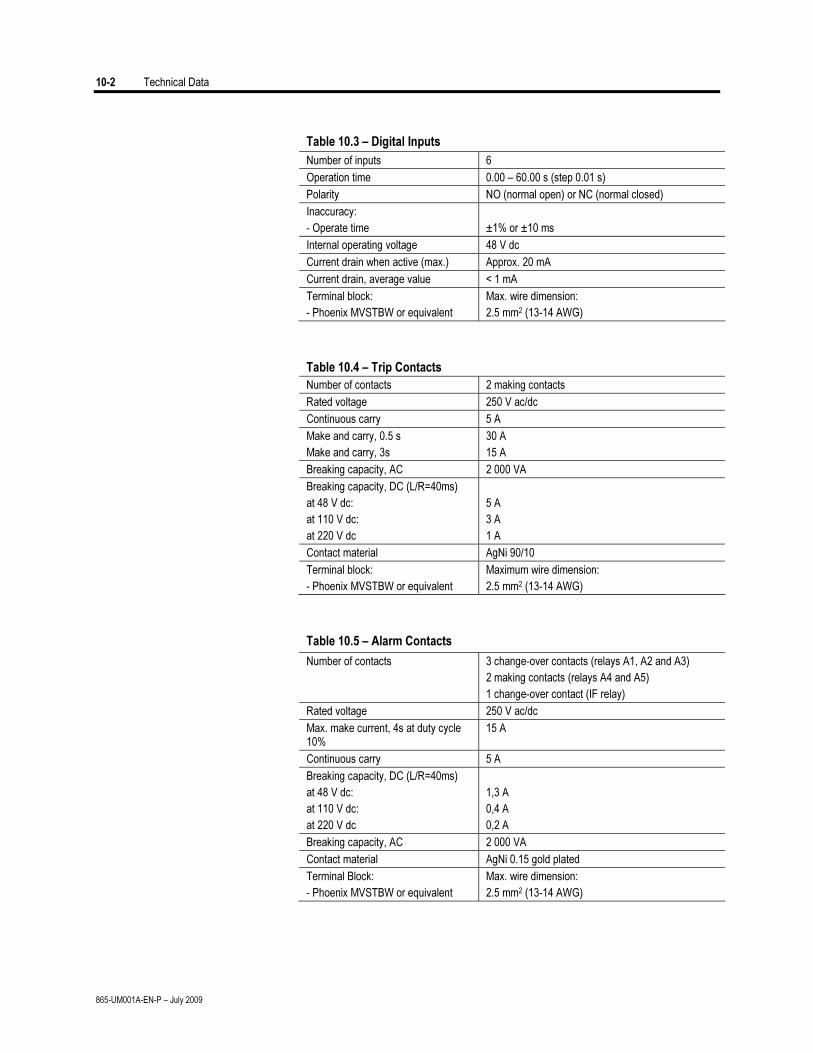
10-2 Technical Data
865-UM001A-EN-P – July 2009
Table 10.3 – Digital Inputs
Number of inputs 6
Operation time 0.00 – 60.00 s (step 0.01 s)
Polarity NO (normal open) or NC (normal closed)
Inaccuracy:
- Operate time ±1% or ±10 ms
Internal operating voltage 48 V dc
Current drain when active (max.) Approx. 20 mA
Current drain, average value < 1 mA
Terminal block: Max. wire dimension:
- Phoenix MVSTBW or equivalent 2.5 mm2 (13-14 AWG)
Table 10.4 – Trip Contacts
Number of contacts 2 making contacts
Rated voltage 250 V ac/dc
Continuous carry 5 A
Make and carry, 0.5 s
Make and carry, 3s
30 A
15 A
Breaking capacity, AC 2 000 VA
Breaking capacity, DC (L/R=40ms)
at 48 V dc:
at 110 V dc:
at 220 V dc
5 A
3 A
1 A
Contact material AgNi 90/10
Terminal block: Maximum wire dimension:
- Phoenix MVSTBW or equivalent 2.5 mm2 (13-14 AWG)
Table 10.5 – Alarm Contacts
Number of contacts 3 change-over contacts (relays A1, A2 and A3)
2 making contacts (relays A4 and A5)
1 change-over contact (IF relay)
Rated voltage 250 V ac/dc
Max. make current, 4s at duty cycle 10%
15 A
Continuous carry 5 A
Breaking capacity, DC (L/R=40ms)
at 48 V dc:
at 110 V dc:
at 220 V dc
1,3 A
0,4 A
0,2 A
Breaking capacity, AC 2 000 VA
Contact material AgNi 0.15 gold plated
Terminal Block: Max. wire dimension:
- Phoenix MVSTBW or equivalent 2.5 mm2 (13-14 AWG)
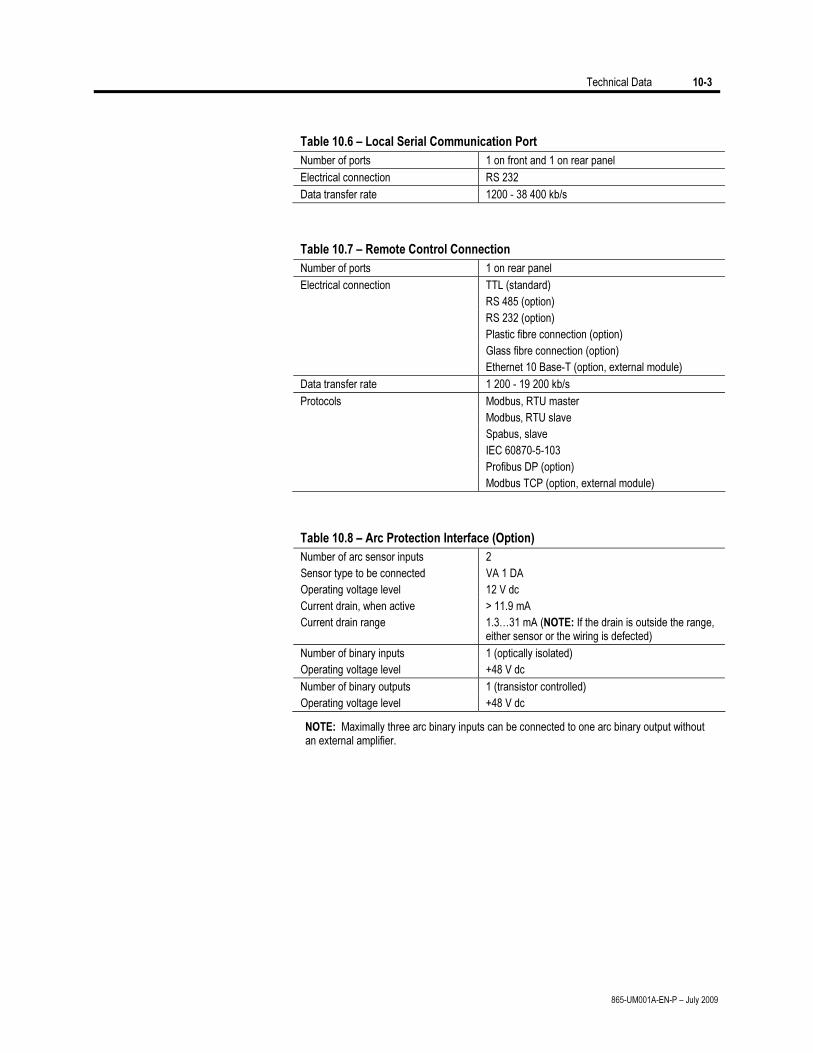
Technical Data 10-3
865-UM001A-EN-P – July 2009
Table 10.6 – Local Serial Communication Port
Number of ports 1 on front and 1 on rear panel
Electrical connection RS 232
Data transfer rate 1200 - 38 400 kb/s
Table 10.7 – Remote Control Connection
Number of ports 1 on rear panel
Electrical connection TTL (standard)
RS 485 (option)
RS 232 (option)
Plastic fibre connection (option)
Glass fibre connection (option)
Ethernet 10 Base-T (option, external module)
Data transfer rate 1 200 - 19 200 kb/s
Protocols Modbus, RTU master
Modbus‚ RTU slave
Spabus, slave
IEC 60870-5-103
Profibus DP (option)
Modbus TCP (option, external module)
Table 10.8 – Arc Protection Interface (Option)
Number of arc sensor inputs 2
Sensor type to be connected VA 1 DA
Operating voltage level 12 V dc
Current drain, when active > 11.9 mA
Current drain range 1.3…31 mA (NOTE: If the drain is outside the range, either sensor or the wiring is defected)
Number of binary inputs 1 (optically isolated)
Operating voltage level +48 V dc
Number of binary outputs 1 (transistor controlled)
Operating voltage level +48 V dc
NOTE: Maximally three arc binary inputs can be connected to one arc binary output without an external amplifier.
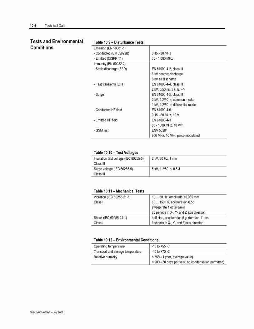
10-4 Technical Data
865-UM001A-EN-P – July 2009
Table 10.9 – Disturbance Tests
Emission (EN 50081-1)
- Conducted (EN 55022B) 0.15 - 30 MHz
- Emitted (CISPR 11) 30 - 1 000 MHz
Immunity (EN 50082-2)
- Static discharge (ESD) EN 61000-4-2, class III
6 kV contact discharge
8 kV air discharge
- Fast transients (EFT) EN 61000-4-4, class III
2 kV, 5/50 ns, 5 kHz, +/-
- Surge EN 61000-4-5, class III
2 kV, 1.2/50 s, common mode
1 kV, 1.2/50 s, differential mode
- Conducted HF field EN 61000-4-6
0.15 - 80 MHz, 10 V
- Emitted HF field EN 61000-4-3
80 - 1000 MHz, 10 V/m
- GSM test ENV 50204
900 MHz, 10 V/m, pulse modulated
Table 10.10 – Test Voltages
Insulation test voltage (IEC 60255-5)
Class III
2 kV, 50 Hz, 1 min
Surge voltage (IEC 60255-5)
Class III
5 kV, 1.2/50 s, 0.5 J
Table 10.11 – Mechanical Tests
Vibration (IEC 60255-21-1) 10 ... 60 Hz, amplitude ±0.035 mm
Class I 60 ... 150 Hz, acceleration 0.5g
sweep rate 1 octave/min
20 periods in X-, Y- and Z axis direction
Shock (IEC 60255-21-1) half sine, acceleration 5 g, duration 11 ms
Class I 3 shocks in X-, Y- and Z axis direction
Table 10.12 – Environmental Conditions
Operating temperature -10 to +55 C
Transport and storage temperature -40 to +70 C
Relative humidity < 75% (1 year, average value)
< 90% (30 days per year, no condensation permitted)
Tests and Environmental Conditions
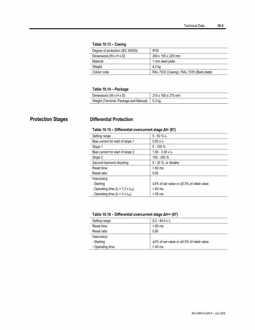
Technical Data 10-5
865-UM001A-EN-P – July 2009
Table 10.13 – Casing
Degree of protection (IEC 60529) IP20
Dimensions (W x H x D) 208 x 155 x 225 mm
Material 1 mm steel plate
Weight 4.2 kg
Colour code RAL 7032 (Casing) / RAL 7035 (Back plate)
Table 10.14 – Package
Dimensions (W x H x D) 215 x 160 x 275 mm
Weight (Terminal, Package and Manual) 5.2 kg
Protection Stages Differential Protection
Table 10.15 – Differential overcurrent stage ΔI> (87)
Setting range 5 - 50 % In
Bias current for start of slope 1 0.50 x In
Slope 1 5 - 100 %
Bias current for start of slope 2 1.00 - 3.00 x In
Slope 2 100 - 200 %
Second harmonic blocking 5 - 30 %, or disable
Reset time < 60 ms
Reset ratio 0.95
Inaccuracy:
- Starting ±3% of set value or ±0.5% of rated value
- Operating time (Id > 1.2 x Iset) < 60 ms
- Operating time (Id > 3 x Iset) < 50 ms
Table 10.16 – Differential overcurrent stage ΔI>> (87)
Setting range 5.0 - 40.0 x In
Reset time < 60 ms
Reset ratio 0.95
Inaccuracy:
- Starting ±3% of set value or ±0.5% of rated value
- Operating time < 40 ms
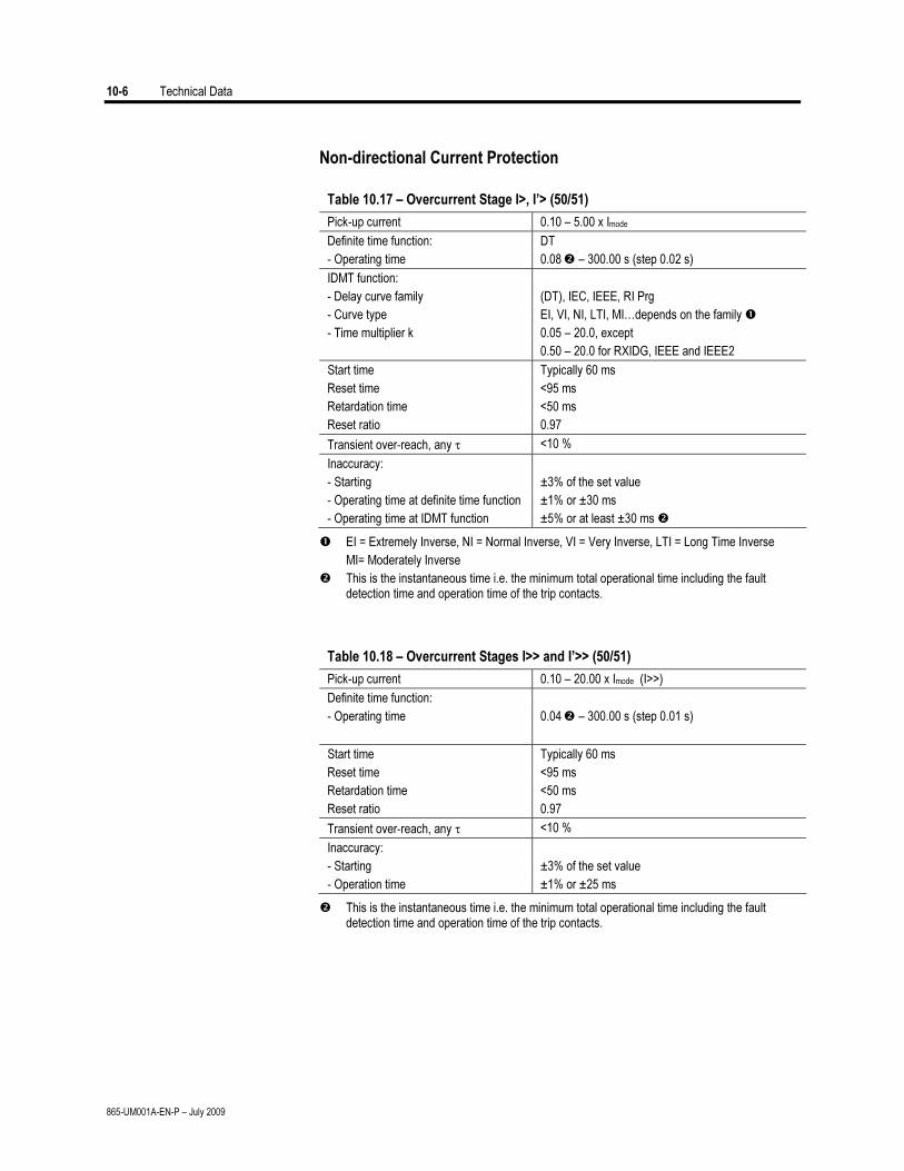
10-6 Technical Data
865-UM001A-EN-P – July 2009
Non-directional Current Protection
Table 10.17 – Overcurrent Stage I>, I’> (50/51)
Pick-up current 0.10 – 5.00 x Imode
Definite time function: DT
- Operating time 0.08 – 300.00 s (step 0.02 s)
IDMT function:
- Delay curve family (DT), IEC, IEEE, RI Prg
- Curve type EI, VI, NI, LTI, MI…depends on the family
- Time multiplier k 0.05 – 20.0, except
0.50 – 20.0 for RXIDG, IEEE and IEEE2
Start time Typically 60 ms
Reset time <95 ms
Retardation time <50 ms
Reset ratio 0.97
Transient over-reach, any τ <10 %
Inaccuracy:
- Starting ±3% of the set value
- Operating time at definite time function ±1% or ±30 ms
- Operating time at IDMT function ±5% or at least ±30 ms
EI = Extremely Inverse, NI = Normal Inverse, VI = Very Inverse, LTI = Long Time Inverse
MI= Moderately Inverse
This is the instantaneous time i.e. the minimum total operational time including the fault detection time and operation time of the trip contacts.
Table 10.18 – Overcurrent Stages I>> and I’>> (50/51)
Pick-up current 0.10 – 20.00 x Imode (I>>)
Definite time function:
0.04 – 300.00 s (step 0.01 s) - Operating time
Start time Typically 60 ms
Reset time <95 ms
Retardation time <50 ms
Reset ratio 0.97
Transient over-reach, any τ <10 %
Inaccuracy:
- Starting ±3% of the set value
- Operation time ±1% or ±25 ms
This is the instantaneous time i.e. the minimum total operational time including the fault detection time and operation time of the trip contacts.
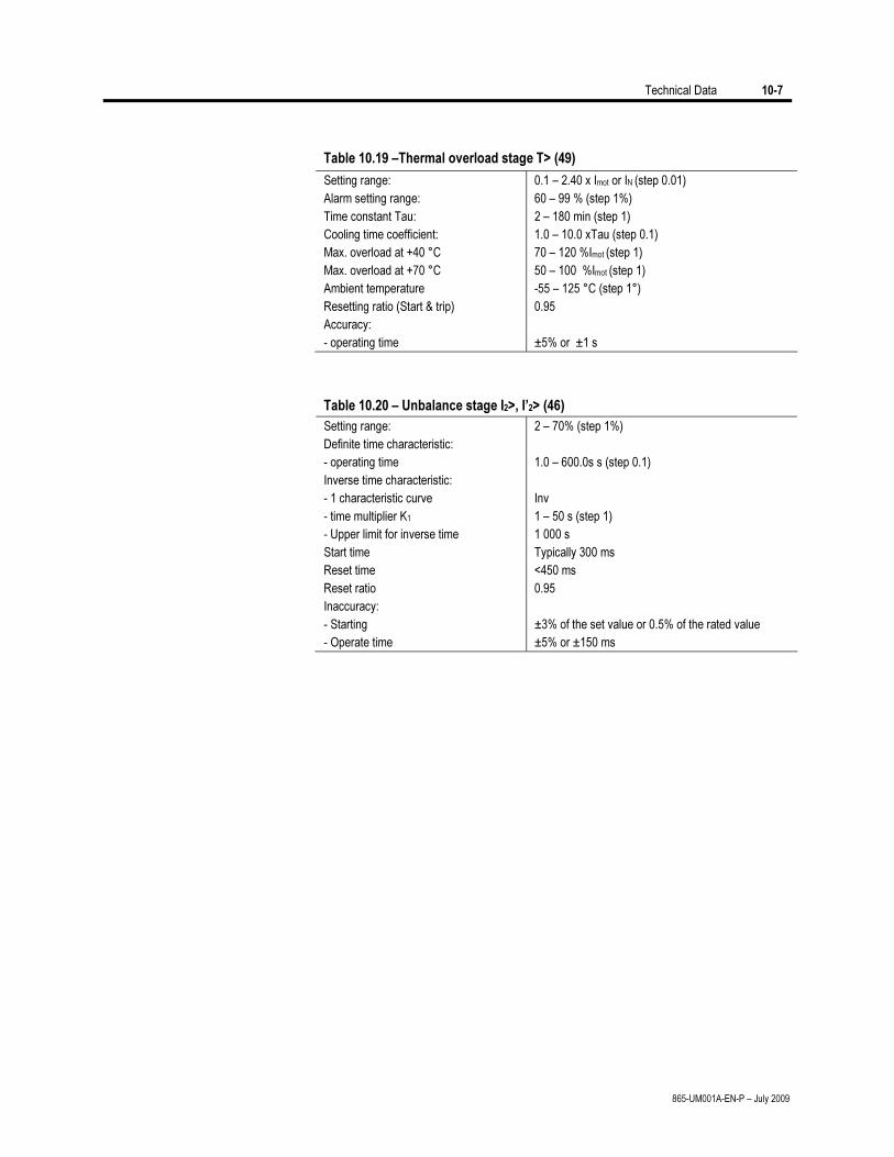
Technical Data 10-7
865-UM001A-EN-P – July 2009
Table 10.19 –Thermal overload stage T> (49)
Setting range: 0.1 – 2.40 x Imot or IN (step 0.01)
Alarm setting range: 60 – 99 % (step 1%)
Time constant Tau: 2 – 180 min (step 1)
Cooling time coefficient: 1.0 – 10.0 xTau (step 0.1)
Max. overload at +40 °C 70 – 120 %Imot (step 1)
Max. overload at +70 °C 50 – 100 %Imot (step 1)
Ambient temperature -55 – 125 °C (step 1°)
Resetting ratio (Start & trip) 0.95
Accuracy:
- operating time ±5% or ±1 s
Table 10.20 – Unbalance stage I2>, I’2> (46)
Setting range: 2 – 70% (step 1%)
Definite time characteristic:
- operating time 1.0 – 600.0s s (step 0.1)
Inverse time characteristic:
- 1 characteristic curve
- time multiplier K1
- Upper limit for inverse time
Inv
1 – 50 s (step 1)
1 000 s
Start time Typically 300 ms
Reset time <450 ms
Reset ratio 0.95
Inaccuracy:
- Starting
- Operate time
±3% of the set value or 0.5% of the rated value
±5% or ±150 ms
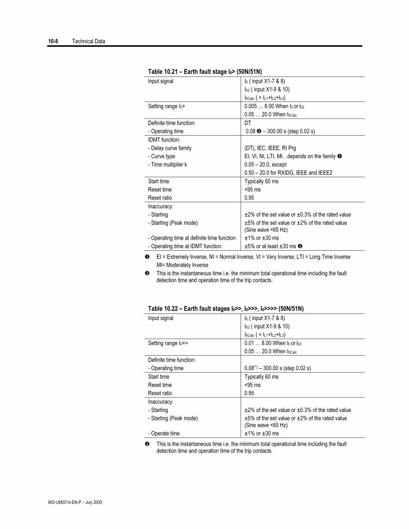
10-8 Technical Data
865-UM001A-EN-P – July 2009
Table 10.21 – Earth fault stage I0> (50N/51N)
Input signal I0 ( input X1-7 & 8)
I02 ( input X1-9 & 10)
I0Calc ( = IL1+IL2+IL3)
Setting range I0> 0.005 … 8.00 When I0 or I02
0.05 … 20.0 When I0Calc
Definite time function: DT
- Operating time 0.08 – 300.00 s (step 0.02 s)
IDMT function:
- Delay curve family (DT), IEC, IEEE, RI Prg
- Curve type EI, VI, NI, LTI, MI…depends on the family
- Time multiplier k 0.05 – 20.0, except
0.50 – 20.0 for RXIDG, IEEE and IEEE2
Start time Typically 60 ms
Reset time <95 ms
Reset ratio 0.95
Inaccuracy:
- Starting ±2% of the set value or ±0.3% of the rated value
- Starting (Peak mode) ±5% of the set value or ±2% of the rated value (Sine wave <65 Hz)
- Operating time at definite time function ±1% or ±30 ms
- Operating time at IDMT function. ±5% or at least ±30 ms
EI = Extremely Inverse, NI = Normal Inverse, VI = Very Inverse, LTI = Long Time Inverse
MI= Moderately Inverse
This is the instantaneous time i.e. the minimum total operational time including the fault detection time and operation time of the trip contacts.
Table 10.22 – Earth fault stages I0>>, I0>>>, I0>>>> (50N/51N)
Input signal I0 ( input X1-7 & 8)
I02 ( input X1-9 & 10)
I0Calc ( = IL1+IL2+IL3)
Setting range I0>> 0.01 … 8.00 When I0 or I02
0.05 … 20.0 When I0Calc
Definite time function:
- Operating time 0.08**) – 300.00 s (step 0.02 s)
Start time Typically 60 ms
Reset time <95 ms
Reset ratio 0.95
Inaccuracy:
- Starting ±2% of the set value or ±0.3% of the rated value
- Starting (Peak mode) ±5% of the set value or ±2% of the rated value (Sine wave <65 Hz)
- Operate time ±1% or ±30 ms
This is the instantaneous time i.e. the minimum total operational time including the fault detection time and operation time of the trip contacts.
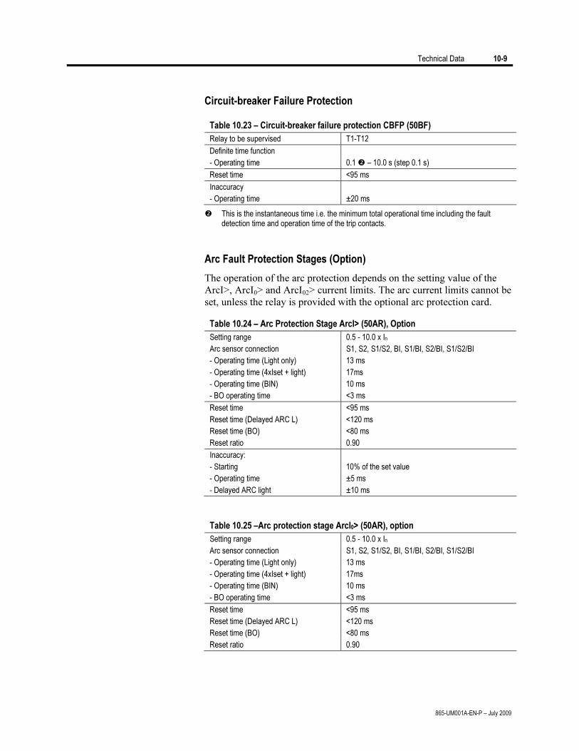
Technical Data 10-9
865-UM001A-EN-P – July 2009
Circuit-breaker Failure Protection
Table 10.23 – Circuit-breaker failure protection CBFP (50BF)
Relay to be supervised T1-T12
Definite time function
- Operating time 0.1 – 10.0 s (step 0.1 s)
Reset time <95 ms
Inaccuracy
- Operating time ±20 ms
This is the instantaneous time i.e. the minimum total operational time including the fault detection time and operation time of the trip contacts.
Arc Fault Protection Stages (Option)
The operation of the arc protection depends on the setting value of the
ArcI>, ArcI0> and ArcI02> current limits. The arc current limits cannot be
set, unless the relay is provided with the optional arc protection card.
Table 10.24 – Arc Protection Stage ArcI> (50AR), Option
Setting range 0.5 - 10.0 x In
Arc sensor connection S1, S2, S1/S2, BI, S1/BI, S2/BI, S1/S2/BI
- Operating time (Light only) 13 ms
- Operating time (4xIset + light) 17ms
- Operating time (BIN) 10 ms
- BO operating time <3 ms
Reset time <95 ms
Reset time (Delayed ARC L) <120 ms
Reset time (BO) <80 ms
Reset ratio 0.90
Inaccuracy:
- Starting 10% of the set value
- Operating time ±5 ms
- Delayed ARC light ±10 ms
Table 10.25 –Arc protection stage ArcI0> (50AR), option
Setting range 0.5 - 10.0 x In
Arc sensor connection S1, S2, S1/S2, BI, S1/BI, S2/BI, S1/S2/BI
- Operating time (Light only) 13 ms
- Operating time (4xIset + light) 17ms
- Operating time (BIN) 10 ms
- BO operating time <3 ms
Reset time <95 ms
Reset time (Delayed ARC L) <120 ms
Reset time (BO) <80 ms
Reset ratio 0.90
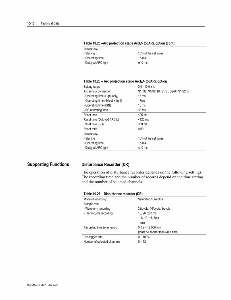
10-10 Technical Data
865-UM001A-EN-P – July 2009
Table 10.25 –Arc protection stage ArcI0> (50AR), option (cont.)
Inaccuracy:
- Starting 10% of the set value
- Operating time ±5 ms
- Delayed ARC light ±10 ms
Table 10.26 – Arc protection stage ArcI02> (50AR), option
Setting range 0.5 - 10.0 x In
Arc sensor connection S1, S2, S1/S2, BI, S1/BI, S2/BI, S1/S2/BI
- Operating time (Light only) 13 ms
- Operating time (4xIset + light) 17ms
- Operating time (BIN) 10 ms
- BO operating time <3 ms
Reset time <95 ms
Reset time (Delayed ARC L) <120 ms
Reset time (BO) <80 ms
Reset ratio 0.90
Inaccuracy:
- Starting 10% of the set value
- Operating time ±5 ms
- Delayed ARC light ±10 ms
Supporting Functions Disturbance Recorder (DR)
The operation of disturbance recorder depends on the following settings.
The recording time and the number of records depend on the time setting
and the number of selected channels.
Table 10.27 – Disturbance recorder (DR)
Mode of recording: Saturated / Overflow
Sample rate:
- Waveform recording
- Trend curve recording
32/cycle, 16/cycle, 8/cycle
10, 20, 200 ms
1, 5, 10, 15, 30 s
1 min
Recording time (one record)
0.1 s – 12 000 min
(must be shorter than MAX time)
Pre-trigger rate 0 – 100%
Number of selected channels 0 – 12
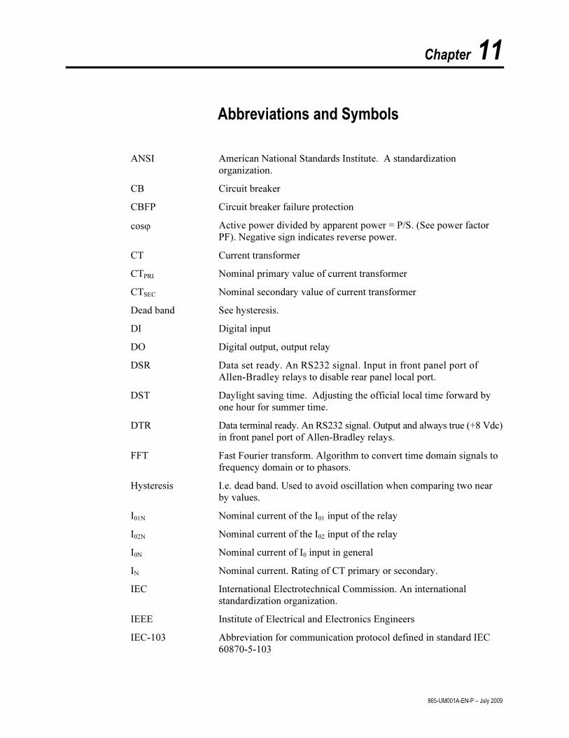
Chapter 11
865-UM001A-EN-P – July 2009
Abbreviations and Symbols
ANSI American National Standards Institute. A standardization
organization.
CB Circuit breaker
CBFP Circuit breaker failure protection
cosϕ Active power divided by apparent power = P/S. (See power factor
PF). Negative sign indicates reverse power.
CT Current transformer
CTPRI Nominal primary value of current transformer
CTSEC Nominal secondary value of current transformer
Dead band See hysteresis.
DI Digital input
DO Digital output, output relay
DSR Data set ready. An RS232 signal. Input in front panel port of
Allen-Bradley relays to disable rear panel local port.
DST Daylight saving time. Adjusting the official local time forward by
one hour for summer time.
DTR Data terminal ready. An RS232 signal. Output and always true (+8 Vdc)
in front panel port of Allen-Bradley relays.
FFT Fast Fourier transform. Algorithm to convert time domain signals to
frequency domain or to phasors.
Hysteresis I.e. dead band. Used to avoid oscillation when comparing two near
by values.
I01N Nominal current of the I01 input of the relay
I02N Nominal current of the I02 input of the relay
I0N Nominal current of I0 input in general
IN Nominal current. Rating of CT primary or secondary.
IEC International Electrotechnical Commission. An international
standardization organization.
IEEE Institute of Electrical and Electronics Engineers
IEC-103 Abbreviation for communication protocol defined in standard IEC
60870-5-103
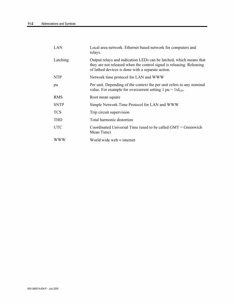
11-2 Abbreviations and Symbols
865-UM001A-EN-P – July 2009
LAN Local area network. Ethernet based network for computers and
relays.
Latching Output relays and indication LEDs can be latched, which means that
they are not released when the control signal is releasing. Releasing
of lathed devices is done with a separate action.
NTP Network time protocol for LAN and WWW
pu Per unit. Depending of the context the per unit refers to any nominal
value. For example for overcurrent setting 1 pu = 1xIGN.
RMS Root mean square
SNTP Simple Network Time Protocol for LAN and WWW
TCS Trip circuit supervision
THD Total harmonic distortion
UTC Coordinated Universal Time (used to be called GMT = Greenwich
Mean Time)
WWW World wide web ≈ internet
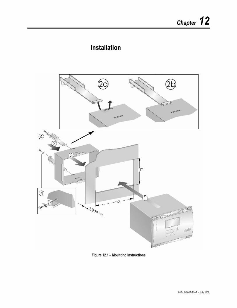
Chapter 12
865-UM001A-EN-P – July 2009
Installation
Figure 12.1 – Mounting Instructions
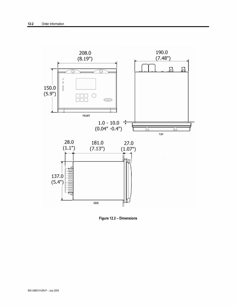
12-2 Order Information
865-UM001A-EN-P – July 2009
Figure 12.2 – Dimensions


Medium Voltage Products, 135 Dundas Street, Cambridge, ON, N1R 5X1 Canada, Tel: (1) 519.740.4100, Fax: (1) 519.623.8930, www.ab.com/mvb
Publication 865-UM001A-EN-P – July 2009 Copyright © 2009 Rockwell Automation, Inc. All rights reserved. Printed in Canada