Embed Size (px)
Citation preview
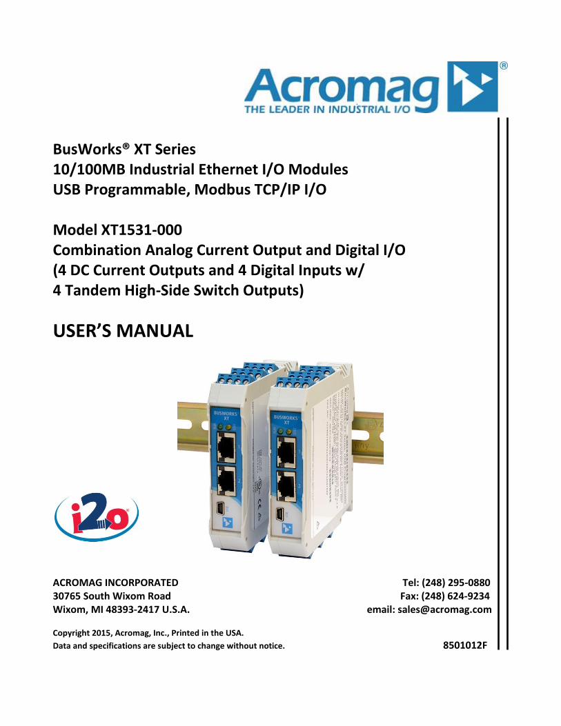
BusWorks® XT Series 10/100MB Industrial Ethernet I/O Modules USB Programmable, Modbus TCP/IP I/O Model XT1531-000 Combination Analog Current Output and Digital I/O (4 DC Current Outputs and 4 Digital Inputs w/ 4 Tandem High-Side Switch Outputs)
USER’S MANUAL
ACROMAG INCORPORATED Tel: (248) 295-0880 30765 South Wixom Road Fax: (248) 624-9234 Wixom, MI 48393-2417 U.S.A. email: [email protected] Copyright 2015, Acromag, Inc., Printed in the USA.
Data and specifications are subject to change without notice. 8501012F
BusWorks Model XT1531-000
4 CH Current Output + 4 CH Digital I/O w/USB & Modbus
Acromag, Inc. Tel: 248-295-0880 - 2 - http://www.acromag.com
- 2 - http://www.acromag.com
Table of Contents
GETTING STARTED
DESCRIPTION ....................................................................................................... 4
Key Features ........................................................................................................................ 4
Application .......................................................................................................................... 4
Mechanical Dimensions ....................................................................................................... 5
DIN Rail Mounting & Removal .............................................................................................. 5
ELECTRICAL CONNECTIONS ............................................................................ 6
Power Connections .............................................................................................................. 7
USB Connection ................................................................................................................... 8
Output Connections ............................................................................................................. 9
Digital Input Connections ................................................................................................... 12
EMI Filter Installation ......................................................................................................... 13
Earth Ground Connections ................................................................................................. 14
CONFIGURATION SOFTWARE ...................................................................... 14
Quick Overview ................................................................................................................. 15
CONFIGURATION STEP-BY-STEP ................................................................ 18
Getting Connected ............................................................................................................. 18
Device/Communication Setup ............................................................................................ 19
I/O Config/Test Page .......................................................................................................... 22
Calibration Page ................................................................................................................ 25
i2o Mapping Page .............................................................................................................. 27
Network Home Page .......................................................................................................... 30
BLOCK DIAGRAM ............................................................................................. 31
How It Works ..................................................................................................................... 31
About Modbus TCP/IP ....................................................................................................... 32
IP Addressing ..................................................................................................................... 33
Dynamic Host Configuration Protocol (DHCP) ..................................................................... 34
Domain Name System (DNS) .............................................................................................. 35
MODBUS REGISTERS ...................................................................................... 35
Register Functions ............................................................................................................. 36
Data Types ......................................................................................................................... 37
Register Map ..................................................................................................................... 37
BusWorks Model XT1531-000
4 CH Current Output + 4 CH Digital I/O w/USB & Modbus
Acromag, Inc. Tel: 248-295-0880 - 3 - http://www.acromag.com
- 3 - http://www.acromag.com
TROUBLESHOOTING ....................................................................................... 43
Diagnostics Table ............................................................................................................... 43
Service & Repair Assistance ............................................................................................... 47
ACCESSORIES .................................................................................................... 48
Software Interface Package ................................................................................................ 48
USB Isolator ....................................................................................................................... 48
USB A-B Cable .................................................................................................................... 48
USB A-mini B Cable ............................................................................................................ 48
DIN Rail Bus Connector Kit ................................................................................................. 49
Low EMI Double-Shielded Patch Cable ............................................................................... 49
SPECIFICATIONS .............................................................................................. 50
Model Number .................................................................................................................. 50
Analog Outputs .................................................................................................................. 50
Digital Outputs .................................................................................................................. 52
Digital Inputs ..................................................................................................................... 53
Power ................................................................................................................................ 54
USB Interface ..................................................................................................................... 54
Ethernet Interface .............................................................................................................. 55
Enclosure & Physical .......................................................................................................... 56
Environmental ................................................................................................................... 56
Agency Approvals .............................................................................................................. 57
Reliability Prediction .......................................................................................................... 57
Configuration Controls ....................................................................................................... 57
REVISION HISTORY ............................................................................................. 58
All trademarks are the property of their respective owners. IMPORTANT SAFETY CONSIDERATIONS You must consider the possible negative effects of power, wiring, component, sensor, or software failure in the design of any type of control or monitoring system. This is very important where property loss or human life is involved. It is important that you perform satisfactory overall system design and it is agreed between you and Acromag, that this is your responsibility. The information of this manual may change without notice. Acromag makes no warranty of any kind with regard to this material, including, but not limited to, the implied warranties of merchantability and fitness for a particular purpose. Further, Acromag assumes no responsibility for any errors that may appear in this manual and makes no commitment to update, or keep current, the information contained in this manual. No part of this manual may be copied, or reproduced in any form without the prior written consent of Acromag, Inc.
BusWorks Model XT1531-000
4 CH Current Output + 4 CH Digital I/O w/USB & Modbus
Acromag, Inc. Tel: 248-295-0880 - 4 - http://www.acromag.com
- 4 - http://www.acromag.com
GETTING STARTED
DESCRIPTION
Symbols on equipment:
Means “Refer to User’s Manual (this manual) for additional information”.
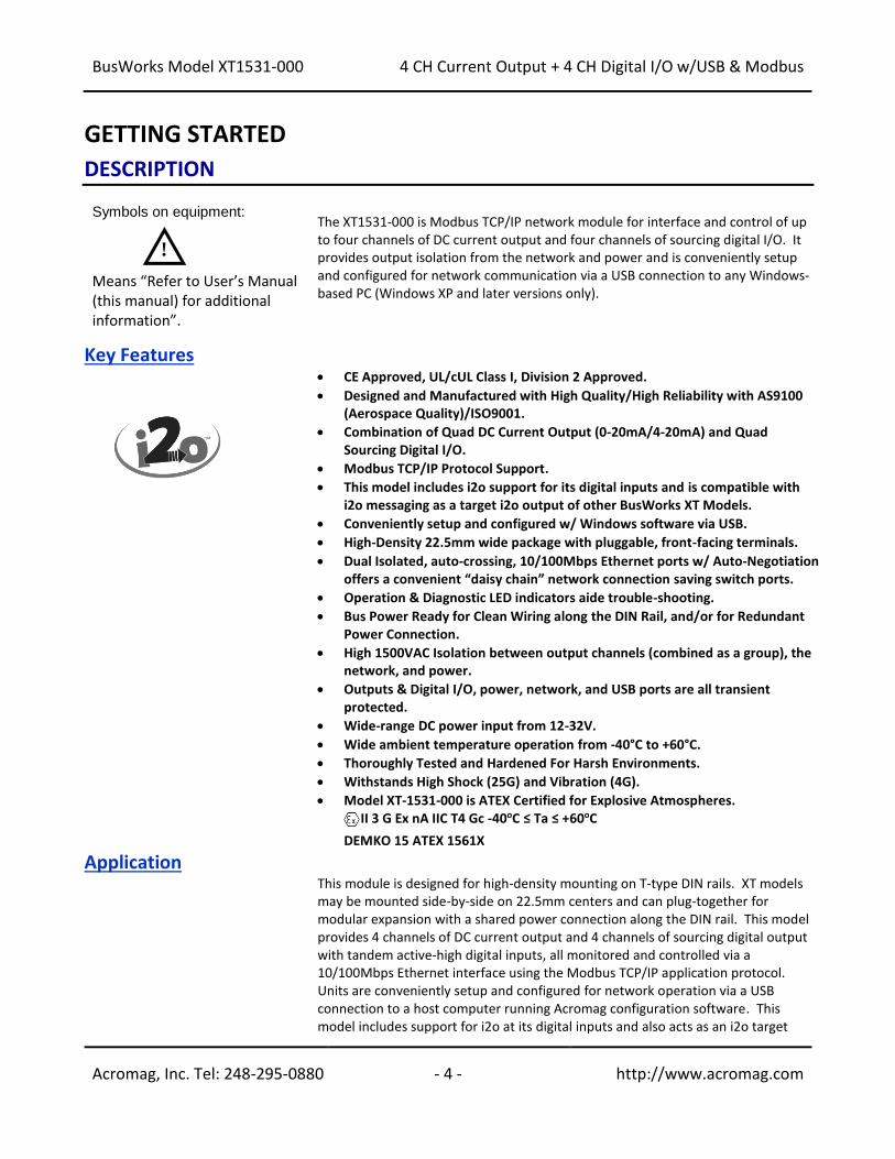
The XT1531-000 is Modbus TCP/IP network module for interface and control of up to four channels of DC current output and four channels of sourcing digital I/O. It provides output isolation from the network and power and is conveniently setup and configured for network communication via a USB connection to any Windows-based PC (Windows XP and later versions only).
Key Features
• CE Approved, UL/cUL Class I, Division 2 Approved.
• Designed and Manufactured with High Quality/High Reliability with AS9100 (Aerospace Quality)/ISO9001.
• Combination of Quad DC Current Output (0-20mA/4-20mA) and Quad Sourcing Digital I/O.
• Modbus TCP/IP Protocol Support.
• This model includes i2o support for its digital inputs and is compatible with i2o messaging as a target i2o output of other BusWorks XT Models.
• Conveniently setup and configured w/ Windows software via USB.
• High-Density 22.5mm wide package with pluggable, front-facing terminals.
• Dual Isolated, auto-crossing, 10/100Mbps Ethernet ports w/ Auto-Negotiation offers a convenient “daisy chain” network connection saving switch ports.
• Operation & Diagnostic LED indicators aide trouble-shooting.
• Bus Power Ready for Clean Wiring along the DIN Rail, and/or for Redundant Power Connection.
• High 1500VAC Isolation between output channels (combined as a group), the network, and power.
• Outputs & Digital I/O, power, network, and USB ports are all transient protected.
• Wide-range DC power input from 12-32V.
• Wide ambient temperature operation from -40°C to +60°C.
• Thoroughly Tested and Hardened For Harsh Environments.
• Withstands High Shock (25G) and Vibration (4G).
• Model XT-1531-000 is ATEX Certified for Explosive Atmospheres. II 3 G Ex nA IIC T4 Gc -40oC ≤ Ta ≤ +60oC
DEMKO 15 ATEX 1561X
Application
This module is designed for high-density mounting on T-type DIN rails. XT models may be mounted side-by-side on 22.5mm centers and can plug-together for modular expansion with a shared power connection along the DIN rail. This model provides 4 channels of DC current output and 4 channels of sourcing digital output with tandem active-high digital inputs, all monitored and controlled via a 10/100Mbps Ethernet interface using the Modbus TCP/IP application protocol. Units are conveniently setup and configured for network operation via a USB connection to a host computer running Acromag configuration software. This model includes support for i2o at its digital inputs and also acts as an i2o target
!
BusWorks Model XT1531-000
4 CH Current Output + 4 CH Digital I/O w/USB & Modbus
Acromag, Inc. Tel: 248-295-0880 - 5 - http://www.acromag.com
- 5 - http://www.acromag.com
output for other XT input models. i2o allows XT input channels to network-link to outputs of other BusWorks models via i2o messaging over the Ethernet network.
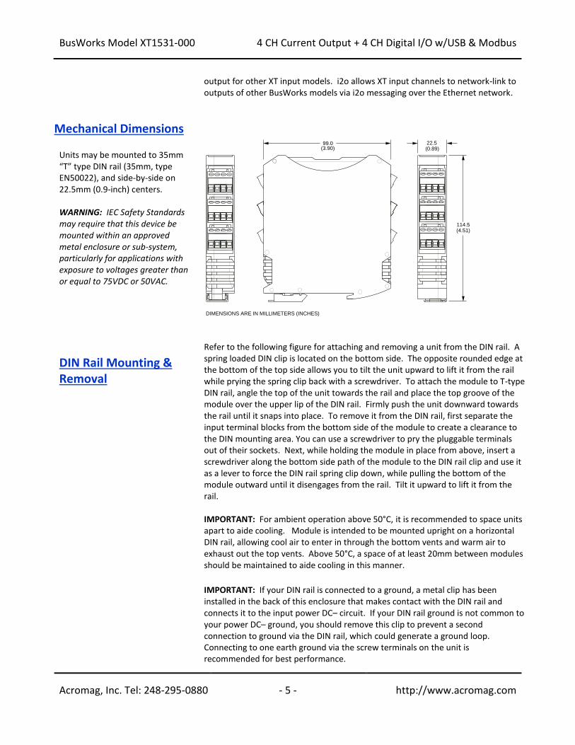
Mechanical Dimensions Units may be mounted to 35mm “T” type DIN rail (35mm, type EN50022), and side-by-side on 22.5mm (0.9-inch) centers. WARNING: IEC Safety Standards may require that this device be mounted within an approved metal enclosure or sub-system, particularly for applications with exposure to voltages greater than or equal to 75VDC or 50VAC.
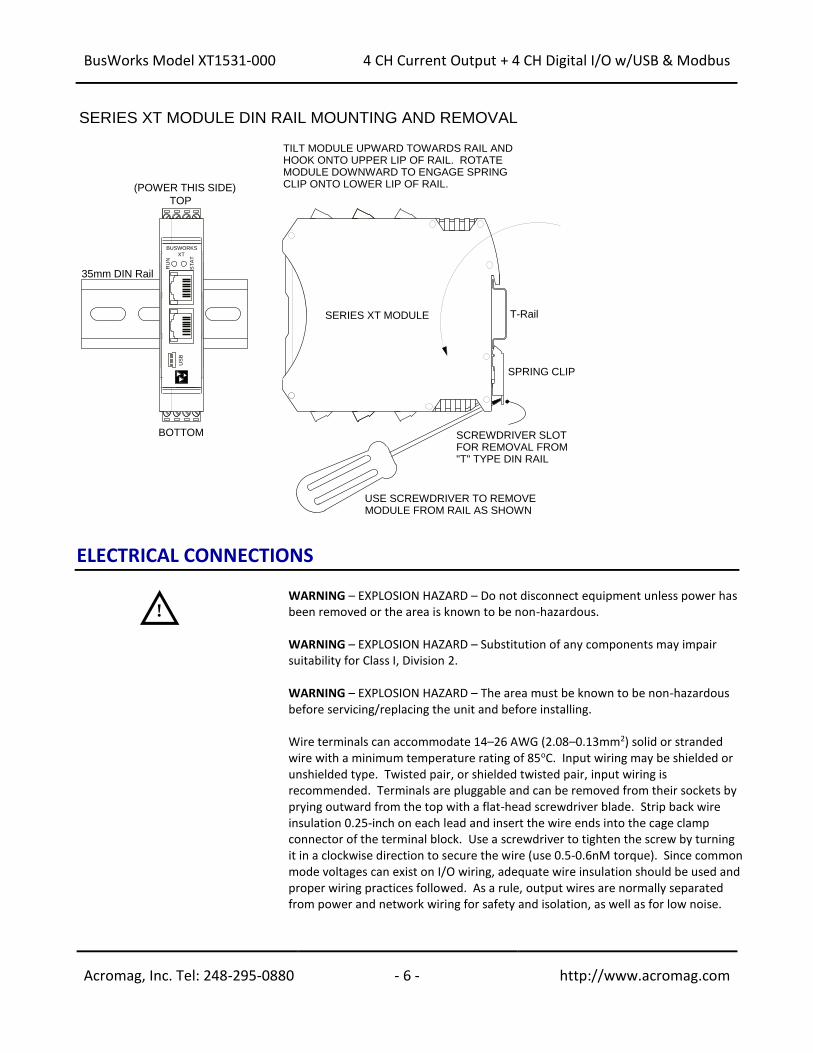
DIN Rail Mounting & Removal
Refer to the following figure for attaching and removing a unit from the DIN rail. A spring loaded DIN clip is located on the bottom side. The opposite rounded edge at the bottom of the top side allows you to tilt the unit upward to lift it from the rail while prying the spring clip back with a screwdriver. To attach the module to T-type DIN rail, angle the top of the unit towards the rail and place the top groove of the module over the upper lip of the DIN rail. Firmly push the unit downward towards the rail until it snaps into place. To remove it from the DIN rail, first separate the input terminal blocks from the bottom side of the module to create a clearance to the DIN mounting area. You can use a screwdriver to pry the pluggable terminals out of their sockets. Next, while holding the module in place from above, insert a screwdriver along the bottom side path of the module to the DIN rail clip and use it as a lever to force the DIN rail spring clip down, while pulling the bottom of the module outward until it disengages from the rail. Tilt it upward to lift it from the rail. IMPORTANT: For ambient operation above 50°C, it is recommended to space units apart to aide cooling. Module is intended to be mounted upright on a horizontal DIN rail, allowing cool air to enter in through the bottom vents and warm air to exhaust out the top vents. Above 50°C, a space of at least 20mm between modules should be maintained to aide cooling in this manner.
IMPORTANT: If your DIN rail is connected to a ground, a metal clip has been installed in the back of this enclosure that makes contact with the DIN rail and connects it to the input power DC– circuit. If your DIN rail ground is not common to your power DC– ground, you should remove this clip to prevent a second connection to ground via the DIN rail, which could generate a ground loop. Connecting to one earth ground via the screw terminals on the unit is recommended for best performance.
99.0(3.90)
114.5(4.51)
22.5(0.89)
DIMENSIONS ARE IN MILLIMETERS (INCHES)
BusWorks Model XT1531-000
4 CH Current Output + 4 CH Digital I/O w/USB & Modbus
Acromag, Inc. Tel: 248-295-0880 - 6 - http://www.acromag.com
- 6 - http://www.acromag.com
ELECTRICAL CONNECTIONS
WARNING – EXPLOSION HAZARD – Do not disconnect equipment unless power has been removed or the area is known to be non-hazardous. WARNING – EXPLOSION HAZARD – Substitution of any components may impair suitability for Class I, Division 2. WARNING – EXPLOSION HAZARD – The area must be known to be non-hazardous before servicing/replacing the unit and before installing. Wire terminals can accommodate 14–26 AWG (2.08–0.13mm2) solid or stranded wire with a minimum temperature rating of 85oC. Input wiring may be shielded or unshielded type. Twisted pair, or shielded twisted pair, input wiring is recommended. Terminals are pluggable and can be removed from their sockets by prying outward from the top with a flat-head screwdriver blade. Strip back wire insulation 0.25-inch on each lead and insert the wire ends into the cage clamp connector of the terminal block. Use a screwdriver to tighten the screw by turning it in a clockwise direction to secure the wire (use 0.5-0.6nM torque). Since common mode voltages can exist on I/O wiring, adequate wire insulation should be used and proper wiring practices followed. As a rule, output wires are normally separated from power and network wiring for safety and isolation, as well as for low noise.
T-Rail
35mm DIN Rail
SCREWDRIVER SLOTFOR REMOVAL FROM"T" TYPE DIN RAIL
TILT MODULE UPWARD TOWARDS RAIL AND HOOK ONTO UPPER LIP OF RAIL. ROTATE MODULE DOWNWARD TO ENGAGE SPRING CLIP ONTO LOWER LIP OF RAIL.
TOP
BOTTOM
SERIES XT MODULE DIN RAIL MOUNTING AND REMOVAL
SPRING CLIP
USE SCREWDRIVER TO REMOVE MODULE FROM RAIL AS SHOWN
SERIES XT MODULE
(POWER THIS SIDE)
BUSWORKS
XT
US
B
RU
N
ST
AT
!
BusWorks Model XT1531-000
4 CH Current Output + 4 CH Digital I/O w/USB & Modbus
Acromag, Inc. Tel: 248-295-0880 - 7 - http://www.acromag.com
- 7 - http://www.acromag.com
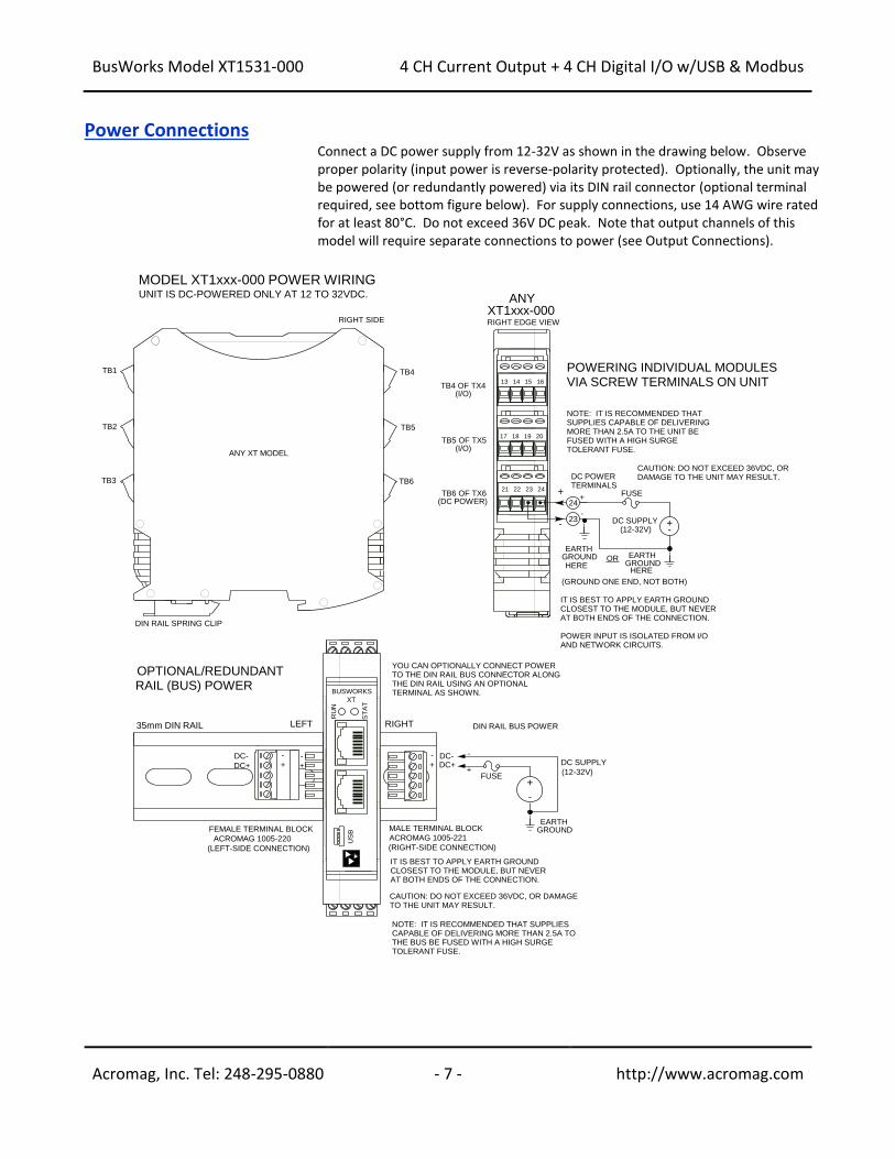
Power Connections Connect a DC power supply from 12-32V as shown in the drawing below. Observe
proper polarity (input power is reverse-polarity protected). Optionally, the unit may be powered (or redundantly powered) via its DIN rail connector (optional terminal required, see bottom figure below). For supply connections, use 14 AWG wire rated for at least 80°C. Do not exceed 36V DC peak. Note that output channels of this model will require separate connections to power (see Output Connections).
MODEL XT1xxx-000 POWER WIRING
+-
DC SUPPLY(12-32V)
EARTHGROUND
DC POWERTERMINALS
TB3
TB4
RIGHT EDGE VIEW
+
-
24
23
UNIT IS DC-POWERED ONLY AT 12 TO 32VDC.
RIGHT SIDE
TB1
DIN RAIL SPRING CLIP
FUSE
POWER INPUT IS ISOLATED FROM I/O AND NETWORK CIRCUITS.
CAUTION: DO NOT EXCEED 36VDC, OR DAMAGE TO THE UNIT MAY RESULT.
NOTE: IT IS RECOMMENDED THAT SUPPLIES CAPABLE OF DELIVERING MORE THAN 2.5A TO THE UNIT BE FUSED WITH A HIGH SURGE TOLERANT FUSE.
TB6 OF TX6
20191817
-
+
ANY
(I/O)
TB5 OF TX5
TB4 OF TX4
(I/O)
(DC POWER)
16151413
XT1xxx-000
TB2 TB5
TB6
35mm DIN RAIL
MALE TERMINAL BLOCK
ACROMAG 1005-221
(RIGHT-SIDE CONNECTION)
FEMALE TERMINAL BLOCK
ACROMAG 1005-220
(LEFT-SIDE CONNECTION)
DC-DC+
DC-
DC+
+
-
DC SUPPLY
(12-32V)
EARTHGROUND
+
-
DIN RAIL BUS POWER
FUSE
CAUTION: DO NOT EXCEED 36VDC, OR DAMAGE TO THE UNIT MAY RESULT.
NOTE: IT IS RECOMMENDED THAT SUPPLIES CAPABLE OF DELIVERING MORE THAN 2.5A TO THE BUS BE FUSED WITH A HIGH SURGE TOLERANT FUSE.
-
+
YOU CAN OPTIONALLY CONNECT POWER TO THE DIN RAIL BUS CONNECTOR ALONG THE DIN RAIL USING AN OPTIONAL TERMINAL AS SHOWN.
LEFT RIGHT
BUSWORKS
XT
US
B
RU
N
ST
AT
+
-
+
-
24232221
OPTIONAL/REDUNDANTRAIL (BUS) POWER
POWERING INDIVIDUAL MODULESVIA SCREW TERMINALS ON UNIT
ANY XT MODEL
EARTHGROUND ORHERE
(GROUND ONE END, NOT BOTH)
IT IS BEST TO APPLY EARTH GROUND CLOSEST TO THE MODULE, BUT NEVER AT BOTH ENDS OF THE CONNECTION.
HERE
IT IS BEST TO APPLY EARTH GROUND CLOSEST TO THE MODULE, BUT NEVER AT BOTH ENDS OF THE CONNECTION.
BusWorks Model XT1531-000
4 CH Current Output + 4 CH Digital I/O w/USB & Modbus
Acromag, Inc. Tel: 248-295-0880 - 8 - http://www.acromag.com
- 8 - http://www.acromag.com
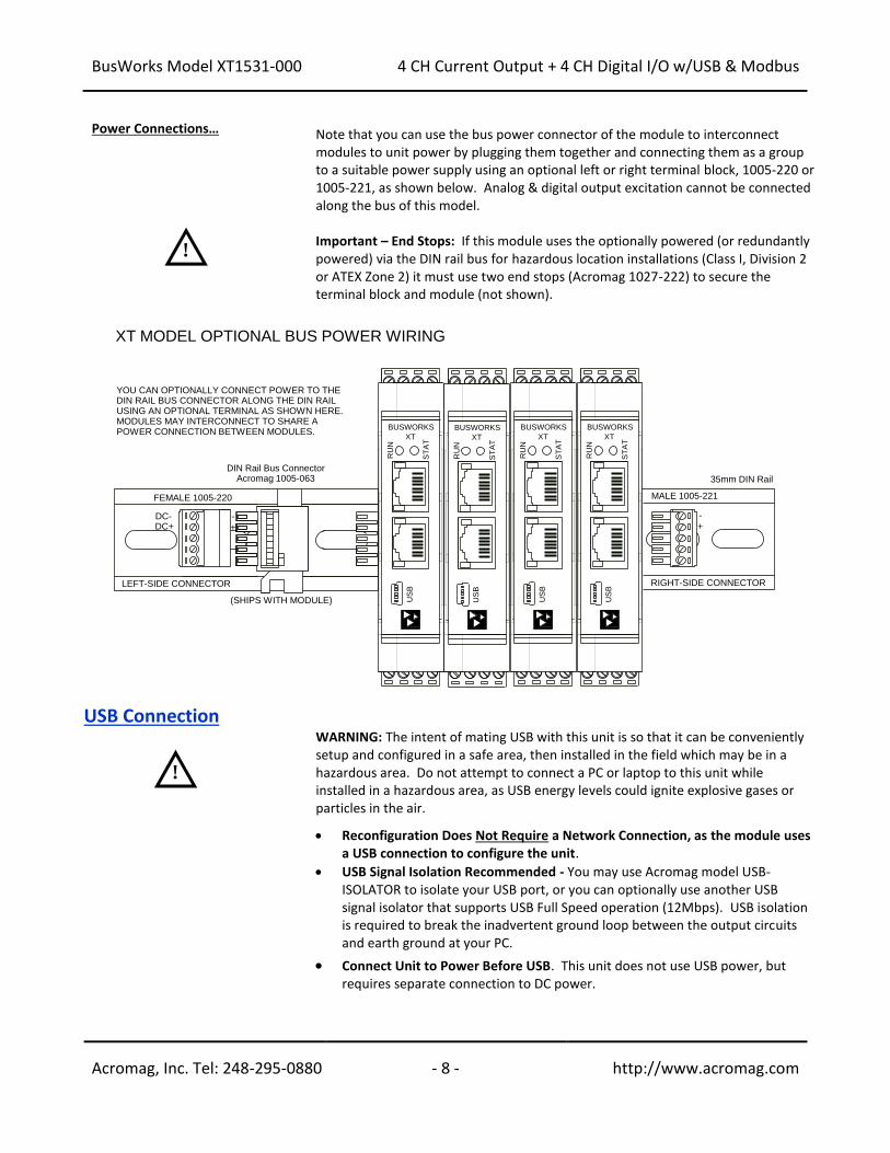
Power Connections… Note that you can use the bus power connector of the module to interconnect modules to unit power by plugging them together and connecting them as a group to a suitable power supply using an optional left or right terminal block, 1005-220 or 1005-221, as shown below. Analog & digital output excitation cannot be connected along the bus of this model. Important – End Stops: If this module uses the optionally powered (or redundantly powered) via the DIN rail bus for hazardous location installations (Class I, Division 2 or ATEX Zone 2) it must use two end stops (Acromag 1027-222) to secure the terminal block and module (not shown).
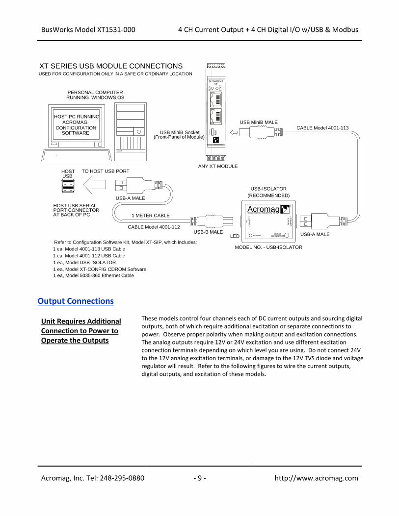
USB Connection WARNING: The intent of mating USB with this unit is so that it can be conveniently
setup and configured in a safe area, then installed in the field which may be in a hazardous area. Do not attempt to connect a PC or laptop to this unit while installed in a hazardous area, as USB energy levels could ignite explosive gases or particles in the air. • Reconfiguration Does Not Require a Network Connection, as the module uses
a USB connection to configure the unit.
• USB Signal Isolation Recommended - You may use Acromag model USB-ISOLATOR to isolate your USB port, or you can optionally use another USB signal isolator that supports USB Full Speed operation (12Mbps). USB isolation is required to break the inadvertent ground loop between the output circuits and earth ground at your PC.
• Connect Unit to Power Before USB. This unit does not use USB power, but requires separate connection to DC power.
35mm DIN Rail
DIN Rail Bus ConnectorAcromag 1005-063
MALE 1005-221
RIGHT-SIDE CONNECTOR
BUSWORKS
XT
US
B
RU
N
ST
AT
BUSWORKS
XT
US
B
RU
N
ST
AT
BUSWORKS
XT
US
B
RU
N
ST
AT
BUSWORKS
XT
US
B
RU
N
ST
AT
-
+DC+DC- -
+
FEMALE 1005-220
LEFT-SIDE CONNECTOR
(SHIPS WITH MODULE)
YOU CAN OPTIONALLY CONNECT POWER TO THE DIN RAIL BUS CONNECTOR ALONG THE DIN RAIL USING AN OPTIONAL TERMINAL AS SHOWN HERE. MODULES MAY INTERCONNECT TO SHARE A POWER CONNECTION BETWEEN MODULES.
XT MODEL OPTIONAL BUS POWER WIRING
!
!
BusWorks Model XT1531-000
4 CH Current Output + 4 CH Digital I/O w/USB & Modbus
Acromag, Inc. Tel: 248-295-0880 - 9 - http://www.acromag.com
- 9 - http://www.acromag.com
Output Connections
Unit Requires Additional Connection to Power to Operate the Outputs
These models control four channels each of DC current outputs and sourcing digital outputs, both of which require additional excitation or separate connections to power. Observe proper polarity when making output and excitation connections. The analog outputs require 12V or 24V excitation and use different excitation connection terminals depending on which level you are using. Do not connect 24V to the 12V analog excitation terminals, or damage to the 12V TVS diode and voltage regulator will result. Refer to the following figures to wire the current outputs, digital outputs, and excitation of these models.
PERSONAL COMPUTERRUNNING WINDOWS OS
1 METER CABLE
USB-A MALE
TO HOST USB PORTHOSTUSB
HOST USB SERIALPORT CONNECTORAT BACK OF PC
CONFIGURATIONSOFTWARE
ACROMAGHOST PC RUNNING
USB-B MALE
DE
VIC
EC
ON
NE
CT
PC
CO
NN
EC
T
POWERRESET
CONNECTION
AcromagTHE LEADER IN INDUSTRIAL I/O
R
USB-A MALE
USB-ISOLATOR
USB MiniB Socket(Front-Panel of Module)
ANY XT MODULE
USB MiniB MALE
XT SERIES USB MODULE CONNECTIONS
LED
(RECOMMENDED)
USED FOR CONFIGURATION ONLY IN A SAFE OR ORDINARY LOCATION
CABLE Model 4001-113
MODEL NO. - USB-ISOLATOR
CABLE Model 4001-112
Refer to Configuration Software Kit, Model XT-SIP, which includes:
1 ea, Model 4001-113 USB Cable
1 ea, Model 4001-112 USB Cable
1 ea, Model USB-ISOLATOR
1 ea, Model XT-CONFIG CDROM Software
BUSWORKS
XT
US
B
RU
N
ST
AT
1 ea, Model 5035-360 Ethernet Cable
BusWorks Model XT1531-000
4 CH Current Output + 4 CH Digital I/O w/USB & Modbus
Acromag, Inc. Tel: 248-295-0880 - 10 - http://www.acromag.com
- 10 - http://www.acromag.com
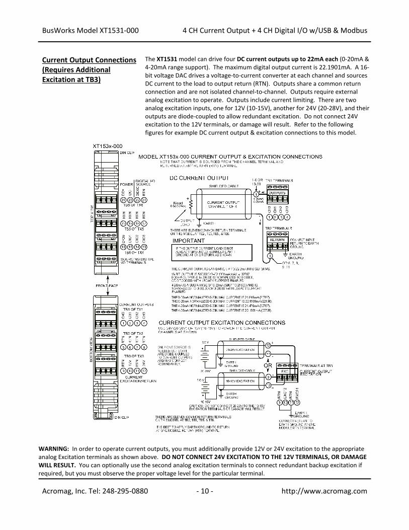
Current Output Connections (Requires Additional Excitation at TB3)
The XT1531 model can drive four DC current outputs up to 22mA each (0-20mA & 4-20mA range support). The maximum digital output current is 22.1901mA. A 16-bit voltage DAC drives a voltage-to-current converter at each channel and sources DC current to the load to output return (RTN). Outputs share a common return connection and are not isolated channel-to-channel. Outputs require external analog excitation to operate. Outputs include current limiting. There are two analog excitation inputs, one for 12V (10-15V), another for 24V (20-28V), and their outputs are diode-coupled to allow redundant excitation. Do not connect 24V excitation to the 12V terminals, or damage will result. Refer to the following figures for example DC current output & excitation connections to this model.
WARNING: In order to operate current outputs, you must additionally provide 12V or 24V excitation to the appropriate analog Excitation terminals as shown above. DO NOT CONNECT 24V EXCITATION TO THE 12V TERMINALS, OR DAMAGE WILL RESULT. You can optionally use the second analog excitation terminals to connect redundant backup excitation if required, but you must observe the proper voltage level for the particular terminal.
BusWorks Model XT1531-000
4 CH Current Output + 4 CH Digital I/O w/USB & Modbus
Acromag, Inc. Tel: 248-295-0880 - 11 - http://www.acromag.com
- 11 - http://www.acromag.com
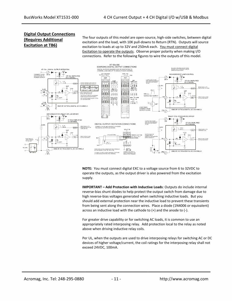
Digital Output Connections (Requires Additional Excitation at TB6)
The four outputs of this model are open-source, high-side switches, between digital excitation and the load, with 10K pull-downs to Return (RTN). Outputs will source excitation to loads at up to 32V and 250mA each. You must connect digital Excitation to operate the outputs. Observe proper polarity when making I/O connections. Refer to the following figures to wire the outputs of this model.
NOTE: You must connect digital EXC to a voltage source from 6 to 32VDC to operate the outputs, as the output driver is also powered from the excitation supply. IMPORTANT – Add Protection with Inductive Loads: Outputs do include internal reverse-bias shunt diodes to help protect the output switch from damage due to high reverse-bias voltages generated when switching inductive loads. But you should add external protection near the inductive load to prevent these transients from being sent along the connection wires. Place a diode (1N4006 or equivalent) across an inductive load with the cathode to (+) and the anode to (-). For greater drive capability or for switching AC loads, it is common to use an appropriately rated interposing relay. Add protection local to the relay as noted above when driving inductive relay coils. Per UL, when the outputs are used to drive interposing relays for switching AC or DC devices of higher voltage/current, the coil ratings for the interposing relay shall not exceed 24VDC, 100mA.
BusWorks Model XT1531-000
4 CH Current Output + 4 CH Digital I/O w/USB & Modbus
Acromag, Inc. Tel: 248-295-0880 - 12 - http://www.acromag.com
- 12 - http://www.acromag.com
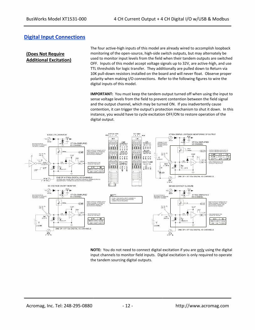
Digital Input Connections
(Does Not Require Additional Excitation)
The four active-high inputs of this model are already wired to accomplish loopback monitoring of the open-source, high-side switch outputs, but may alternately be used to monitor input levels from the field when their tandem outputs are switched OFF. Inputs of this model accept voltage signals up to 32V, are active-high, and use TTL thresholds for logic transfer. They additionally are pulled down to Return via 10K pull-down resistors installed on the board and will never float. Observe proper polarity when making I/O connections. Refer to the following figures to wire the digital inputs of this model. IMPORTANT: You must keep the tandem output turned off when using the input to sense voltage levels from the field to prevent contention between the field signal and the output channel, which may be turned ON. If you inadvertently cause contention, it can trigger the output’s protection mechanism to shut it down. In this instance, you would have to cycle excitation OFF/ON to restore operation of the digital output.
NOTE: You do not need to connect digital excitation if you are only using the digital input channels to monitor field inputs. Digital excitation is only required to operate the tandem sourcing digital outputs.
BusWorks Model XT1531-000
4 CH Current Output + 4 CH Digital I/O w/USB & Modbus
Acromag, Inc. Tel: 248-295-0880 - 13 - http://www.acromag.com
- 13 - http://www.acromag.com
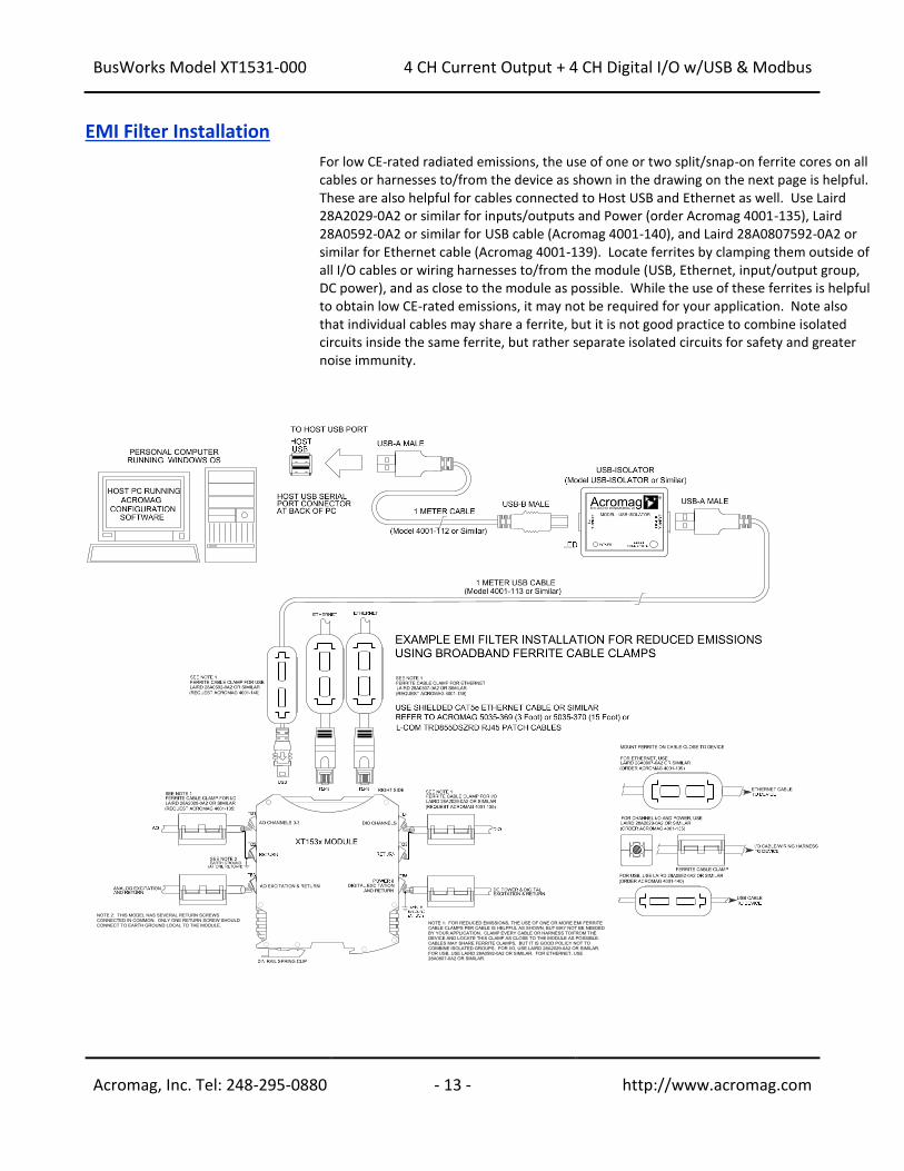
EMI Filter Installation
For low CE-rated radiated emissions, the use of one or two split/snap-on ferrite cores on all cables or harnesses to/from the device as shown in the drawing on the next page is helpful. These are also helpful for cables connected to Host USB and Ethernet as well. Use Laird 28A2029-0A2 or similar for inputs/outputs and Power (order Acromag 4001-135), Laird 28A0592-0A2 or similar for USB cable (Acromag 4001-140), and Laird 28A0807592-0A2 or similar for Ethernet cable (Acromag 4001-139). Locate ferrites by clamping them outside of all I/O cables or wiring harnesses to/from the module (USB, Ethernet, input/output group, DC power), and as close to the module as possible. While the use of these ferrites is helpful to obtain low CE-rated emissions, it may not be required for your application. Note also that individual cables may share a ferrite, but it is not good practice to combine isolated circuits inside the same ferrite, but rather separate isolated circuits for safety and greater noise immunity.
BusWorks Model XT1531-000
4 CH Current Output + 4 CH Digital I/O w/USB & Modbus
Acromag, Inc. Tel: 248-295-0880 - 14 - http://www.acromag.com
- 14 - http://www.acromag.com
Earth Ground Connections
(To Protect Your Equipment, Lower System Noise, and Reduce Emissions)
The unit housing is plastic and does not require an earth ground connection itself. If the module is mounted in a metal housing, an earth ground wire connection to the metal housing’s ground terminal (green screw) is usually required using suitable wire per applicable codes. Circuits wired to inputs/outputs, power, and the network should be earth grounded as well, as reflected in the connection diagrams. The ground connections noted are recommended for best results and help protect the unit by giving it a low impedance path to ground for shunting destructive transient energy away from the module. See the Electrical Connection Drawings for recommended input/output, power, and network ground connections. IMPORTANT: For units mounted to DIN rail, a metal clip has been installed in the back of this enclosure and it makes contact with the DIN rail and connects it to the input power DC– circuit. If your DIN rail ground is not common to your power DC– ground, you should carefully pry the enclosure apart and remove this clip to prevent a second connection to ground via the DIN rail. Connecting to one earth ground via the screw terminals on the unit is recommended for best performance. Note: A USB isolator is recommended when connected to a grounded Personal Computer for configuration purposes. This will avoid an inadvertent ground loop that will occur if your input signal is already earth grounded, as a PC commonly earth grounds its USB port and this makes contact with both the USB signal and shield ground which is held in common to the input circuit return of this module.
CONFIGURATION SOFTWARE While this is an Ethernet network I/O module, it can only be configured and calibrated via its Configuration Software over a USB connection to a Windows-based PC or laptop. USB saves you the trouble of having to already know its IP address setting, or having to change the address setting of your network interface card to match its address domain in order to communicate with it. USB software is contained in a zip file that can be downloaded free of charge from our web site at www.acromag.com. Look for the software zip file 9500465 in the Documents and Downloads page for your XT product. Initially, you will have to answer a few questions to open a user account and download this file to your computer. This zip file will extract to a modelconfig.exe executable file installed in an Acromag subdirectory off the Program Files directory of your PC. Note that you must have administrator rights to download and install this software onto your PC or laptop. Once you have installed the software, be sure to navigate to the Program Files\Acromag subdirectory and select the correct modelconfig.exe software for your particular module. This same software is also included on a CDROM bundled in the Configuration Kit XT-SIP (see Accessories), but downloading it from the web will help to ensure that your software is the most up-to-date available. This software is compatible with XP or later versions of the Windows operating system. Note that the particular modelconfig.exe software for this unit supports five other combinational model variations—three models with 8 voltage outputs, plus three models with 4 current outputs, each including 4 sourcing digital I/O channels.
BusWorks Model XT1531-000
4 CH Current Output + 4 CH Digital I/O w/USB & Modbus
Acromag, Inc. Tel: 248-295-0880 - 15 - http://www.acromag.com
- 15 - http://www.acromag.com
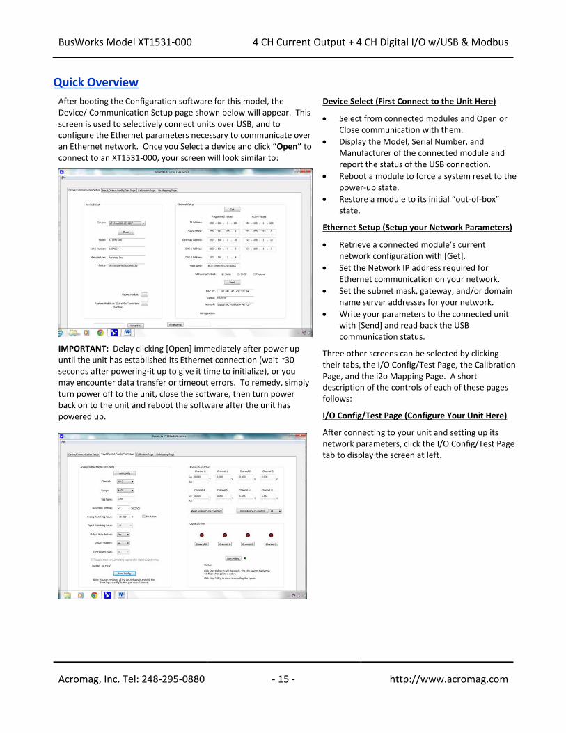
Quick Overview After booting the Configuration software for this model, the Device/ Communication Setup page shown below will appear. This screen is used to selectively connect units over USB, and to configure the Ethernet parameters necessary to communicate over an Ethernet network. Once you Select a device and click “Open” to connect to an XT1531-000, your screen will look similar to:
IMPORTANT: Delay clicking [Open] immediately after power up until the unit has established its Ethernet connection (wait ~30 seconds after powering-it up to give it time to initialize), or you may encounter data transfer or timeout errors. To remedy, simply turn power off to the unit, close the software, then turn power back on to the unit and reboot the software after the unit has powered up.
Device Select (First Connect to the Unit Here) • Select from connected modules and Open or
Close communication with them.
• Display the Model, Serial Number, and Manufacturer of the connected module and report the status of the USB connection.
• Reboot a module to force a system reset to the power-up state.
• Restore a module to its initial “out-of-box” state.
Ethernet Setup (Setup your Network Parameters) • Retrieve a connected module’s current
network configuration with [Get].
• Set the Network IP address required for Ethernet communication on your network.
• Set the subnet mask, gateway, and/or domain name server addresses for your network.
• Write your parameters to the connected unit with [Send] and read back the USB communication status.
Three other screens can be selected by clicking their tabs, the I/O Config/Test Page, the Calibration Page, and the i2o Mapping Page. A short description of the controls of each of these pages follows: I/O Config/Test Page (Configure Your Unit Here) After connecting to your unit and setting up its network parameters, click the I/O Config/Test Page tab to display the screen at left.
BusWorks Model XT1531-000
4 CH Current Output + 4 CH Digital I/O w/USB & Modbus
Acromag, Inc. Tel: 248-295-0880 - 16 - http://www.acromag.com
- 16 - http://www.acromag.com
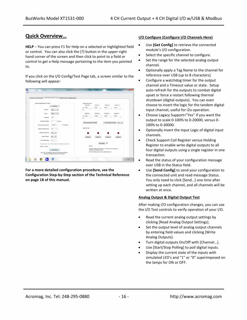
Quick Overview… HELP – You can press F1 for Help on a selected or highlighted field or control. You can also click the [?] button in the upper-right hand corner of the screen and then click to point to a field or control to get a Help message pertaining to the item you pointed to. If you click on the I/O Config/Test Page tab, a screen similar to the following will appear:
For a more detailed configuration procedure, see the Configuration Step-by-Step section of the Technical Reference on page 18 of this manual.
I/O Configure (Configure I/O Channels Here) • Use [Get Config] to retrieve the connected
module’s I/O configuration.
• Select the specific channel to configure.
• Set the range for the selected analog output channel.
• Optionally apply a Tag Name to the channel for reference over USB (up to 8 characters).
• Configure a watchdog timer for the output channel and a Timeout value or state. Setup auto-refresh for the outputs to combat digital upset or force a restart following thermal shutdown (digital outputs). You can even choose to invert the logic for the tandem digital input channel, useful for i2o operation.
• Choose Legacy Support=”Yes” if you want the output to scale 0-100% to 0-20000, versus 0-100% to 0-30000.
• Optionally invert the Input Logic of digital input channels.
• Check Support Coil Register versus Holding Register to enable write digital outputs to all four digital outputs using a single register in one transaction.
• Read the status of your configuration message over USB in the Status field.
• Use [Send Config] to send your configuration to the connected unit and read message Status. You only need to click [Send…] one time after setting up each channel, and all channels will be written at once.
Analog Output & Digital Output Test After making I/O configuration changes, you can use the I/O Test controls to verify operation of your I/O. • Read the current analog output settings by
clicking [Read Analog Output Settings].
• Set the output level of analog output channels by entering field values and clicking [Write Analog Outputs].
• Turn digital outputs On/Off with [Channel…].
• Use [Start/Stop Polling] to poll digital inputs.
• Display the current state of the inputs with simulated LED’s and “1” or “0” superimposed on the lamps for ON or OFF.
BusWorks Model XT1531-000
4 CH Current Output + 4 CH Digital I/O w/USB & Modbus
Acromag, Inc. Tel: 248-295-0880 - 17 - http://www.acromag.com
- 17 - http://www.acromag.com
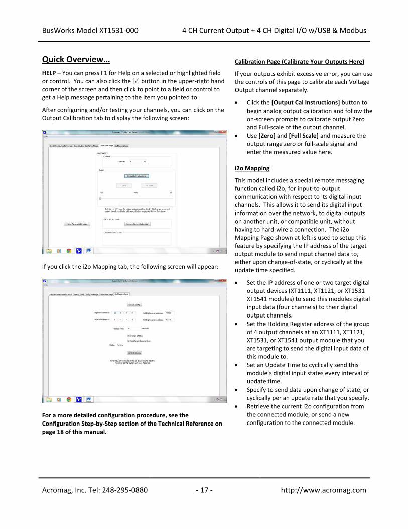
Quick Overview… HELP – You can press F1 for Help on a selected or highlighted field or control. You can also click the [?] button in the upper-right hand corner of the screen and then click to point to a field or control to get a Help message pertaining to the item you pointed to. After configuring and/or testing your channels, you can click on the Output Calibration tab to display the following screen:
If you click the i2o Mapping tab, the following screen will appear:
For a more detailed configuration procedure, see the Configuration Step-by-Step section of the Technical Reference on page 18 of this manual.
Calibration Page (Calibrate Your Outputs Here) If your outputs exhibit excessive error, you can use the controls of this page to calibrate each Voltage Output channel separately. • Click the [Output Cal Instructions] button to
begin analog output calibration and follow the on-screen prompts to calibrate output Zero and Full-scale of the output channel.
• Use [Zero] and [Full Scale] and measure the output range zero or full-scale signal and enter the measured value here.
i2o Mapping This model includes a special remote messaging function called i2o, for input-to-output communication with respect to its digital input channels. This allows it to send its digital input information over the network, to digital outputs on another unit, or compatible unit, without having to hard-wire a connection. The i2o Mapping Page shown at left is used to setup this feature by specifying the IP address of the target output module to send input channel data to, either upon change-of-state, or cyclically at the update time specified. • Set the IP address of one or two target digital
output devices (XT1111, XT1121, or XT1531 XT1541 modules) to send this modules digital input data (four channels) to their digital output channels.
• Set the Holding Register address of the group of 4 output channels at an XT1111, XT1121, XT1531, or XT1541 output module that you are targeting to send the digital input data of this module to.
• Set an Update Time to cyclically send this module’s digital input states every interval of update time.
• Specify to send data upon change of state, or cyclically per an update rate that you specify.
• Retrieve the current i2o configuration from the connected module, or send a new configuration to the connected module.
BusWorks Model XT1531-000
4 CH Current Output + 4 CH Digital I/O w/USB & Modbus
Acromag, Inc. Tel: 248-295-0880 - 18 - http://www.acromag.com
- 18 - http://www.acromag.com
TECHNICAL REFERENCE
CONFIGURATION STEP-BY-STEP
Getting Connected
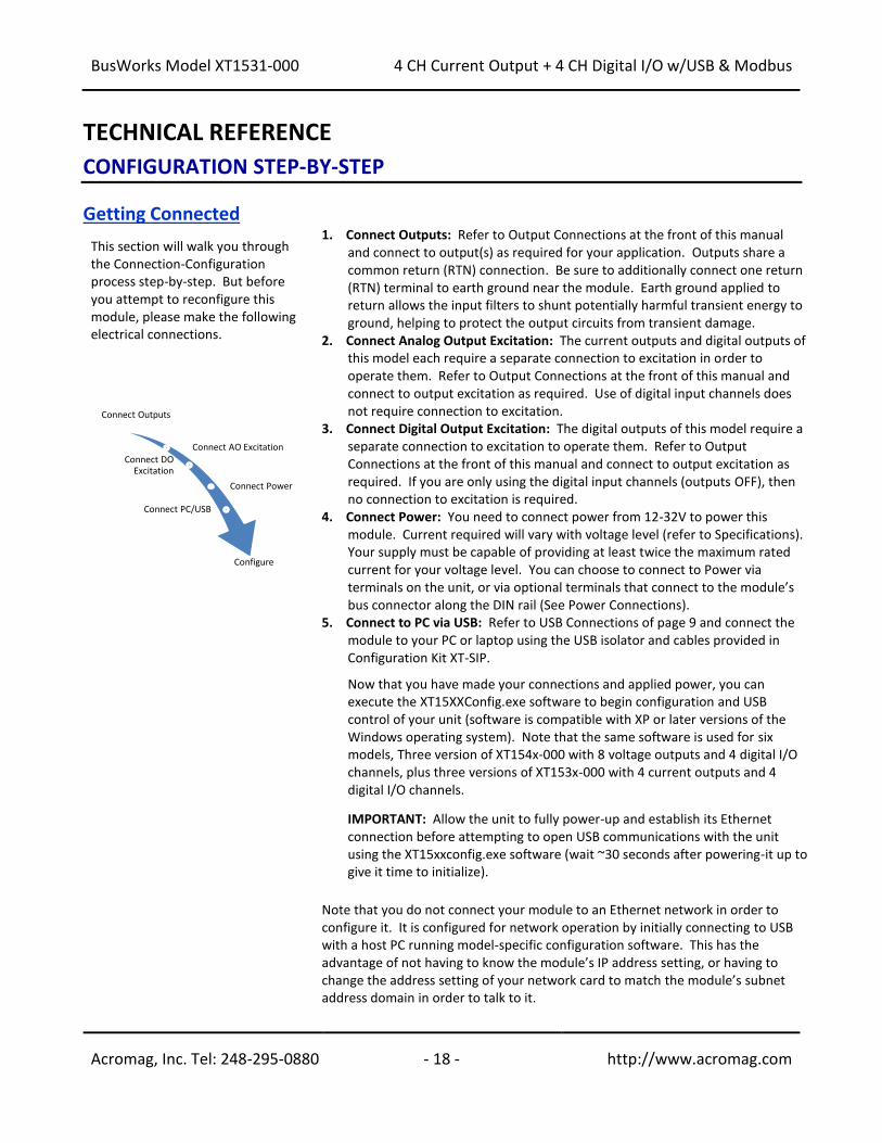
This section will walk you through the Connection-Configuration process step-by-step. But before you attempt to reconfigure this module, please make the following electrical connections.
1. Connect Outputs: Refer to Output Connections at the front of this manual and connect to output(s) as required for your application. Outputs share a common return (RTN) connection. Be sure to additionally connect one return (RTN) terminal to earth ground near the module. Earth ground applied to return allows the input filters to shunt potentially harmful transient energy to ground, helping to protect the output circuits from transient damage.
2. Connect Analog Output Excitation: The current outputs and digital outputs of this model each require a separate connection to excitation in order to operate them. Refer to Output Connections at the front of this manual and connect to output excitation as required. Use of digital input channels does not require connection to excitation.
3. Connect Digital Output Excitation: The digital outputs of this model require a separate connection to excitation to operate them. Refer to Output Connections at the front of this manual and connect to output excitation as required. If you are only using the digital input channels (outputs OFF), then no connection to excitation is required.
4. Connect Power: You need to connect power from 12-32V to power this module. Current required will vary with voltage level (refer to Specifications). Your supply must be capable of providing at least twice the maximum rated current for your voltage level. You can choose to connect to Power via terminals on the unit, or via optional terminals that connect to the module’s bus connector along the DIN rail (See Power Connections).
5. Connect to PC via USB: Refer to USB Connections of page 9 and connect the module to your PC or laptop using the USB isolator and cables provided in Configuration Kit XT-SIP.
Now that you have made your connections and applied power, you can execute the XT15XXConfig.exe software to begin configuration and USB control of your unit (software is compatible with XP or later versions of the Windows operating system). Note that the same software is used for six models, Three version of XT154x-000 with 8 voltage outputs and 4 digital I/O channels, plus three versions of XT153x-000 with 4 current outputs and 4 digital I/O channels.
IMPORTANT: Allow the unit to fully power-up and establish its Ethernet connection before attempting to open USB communications with the unit using the XT15xxconfig.exe software (wait ~30 seconds after powering-it up to give it time to initialize).
Note that you do not connect your module to an Ethernet network in order to configure it. It is configured for network operation by initially connecting to USB with a host PC running model-specific configuration software. This has the advantage of not having to know the module’s IP address setting, or having to change the address setting of your network card to match the module’s subnet address domain in order to talk to it.
Connect Outputs
Connect AO ExcitationConnect DO
Excitation
Connect Power
Connect PC/USB
Configure
BusWorks Model XT1531-000
4 CH Current Output + 4 CH Digital I/O w/USB & Modbus
Acromag, Inc. Tel: 248-295-0880 - 19 - http://www.acromag.com
- 19 - http://www.acromag.com
Device/Communication Setup
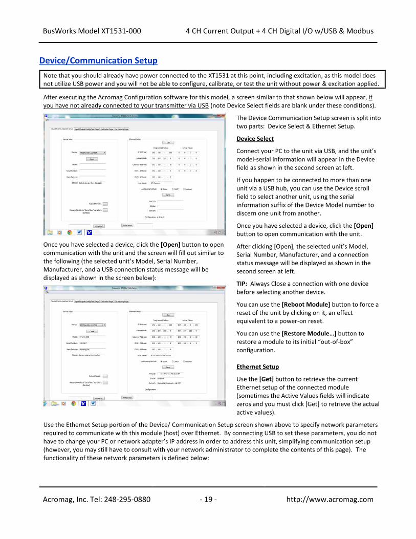
Note that you should already have power connected to the XT1531 at this point, including excitation, as this model does not utilize USB power and you will not be able to configure, calibrate, or test the unit without power & excitation applied. After executing the Acromag Configuration software for this model, a screen similar to that shown below will appear, if you have not already connected to your transmitter via USB (note Device Select fields are blank under these conditions).
Once you have selected a device, click the [Open] button to open communication with the unit and the screen will fill out similar to the following (the selected unit’s Model, Serial Number, Manufacturer, and a USB connection status message will be displayed as shown in the screen below):
The Device Communication Setup screen is split into two parts: Device Select & Ethernet Setup. Device Select Connect your PC to the unit via USB, and the unit’s model-serial information will appear in the Device field as shown in the second screen at left. If you happen to be connected to more than one unit via a USB hub, you can use the Device scroll field to select another unit, using the serial information suffix of the Device Model number to discern one unit from another. Once you have selected a device, click the [Open] button to open communication with the unit. After clicking [Open], the selected unit’s Model, Serial Number, Manufacturer, and a connection status message will be displayed as shown in the second screen at left. TIP: Always Close a connection with one device before selecting another device. You can use the [Reboot Module] button to force a reset of the unit by clicking on it, an effect equivalent to a power-on reset. You can use the [Restore Module…] button to restore a module to its initial “out-of-box” configuration. Ethernet Setup Use the [Get] button to retrieve the current Ethernet setup of the connected module (sometimes the Active Values fields will indicate zeros and you must click [Get] to retrieve the actual active values).
Use the Ethernet Setup portion of the Device/ Communication Setup screen shown above to specify network parameters required to communicate with this module (host) over Ethernet. By connecting USB to set these parameters, you do not have to change your PC or network adapter’s IP address in order to address this unit, simplifying communication setup (however, you may still have to consult with your network administrator to complete the contents of this page). The functionality of these network parameters is defined below:
BusWorks Model XT1531-000
4 CH Current Output + 4 CH Digital I/O w/USB & Modbus
Acromag, Inc. Tel: 248-295-0880 - 20 - http://www.acromag.com
- 20 - http://www.acromag.com
Device/Communication Setup…
The Internet or world-wide web is actually a large network made up of many smaller networks (sub-networks) linked together by gateways or routers. The gateway or router serves as an access point to/from a particular sub-network. For example, your ISP provides DSL modems or cable modems which connect your local hardware to the Internet and often serve as gateways. The gateway address is the address of this gateway or router in the same subnet as the host, and is used as the bridge to connect to various other sub-networks with different sub-network addresses and address masks, that collectively connect together to make up the Internet. Data packets sent over the Internet contain both the sender’s Internet address and the receiver’s address. A packet is first sent to a gateway computer that understands its own domain or group of host addresses. The gateway reads the destination address of the packet, and if it is outside of its own domain, it forwards the packet on to an adjacent gateway that again reads the destination address. Then that gateway will forward the message on, if the address is not within its domain. Eventually, one gateway recognizes the packet as belonging to a host within its domain. Finding a match, that gateway forwards the packet directly to the host whose address is specified. Rather than continually passing a packet from gateway to gateway, some networks will use a default gateway which is the address of another node on the same network that the software uses when an IP address does not match any other routes in the routing table (address domain) of the primary gateway. Ethernet Setup…continued
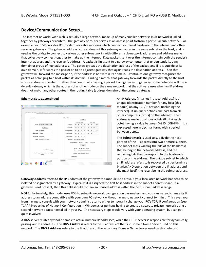
An IP Address (Internet Protocol Address) is a unique identification number for any host (this module) on any TCP/IP network (including the internet). It uniquely defines one host from all other computers (hosts) on the Internet. The IP address is made up of four octets (8 bits), each octet having a value between 0-255 (00H-FFH). It is expressed here in decimal form, with a period between octets. The Subnet Mask is used to subdivide the host portion of the IP address into two or more subnets. The subnet mask will flag the bits of the IP address that belong to the network address, and the remaining bits that correspond to the host/node portion of the address. The unique subnet to which an IP address refers to is recovered by performing a bitwise AND operation between the IP address and the mask itself, the result being the subnet address.
Gateway Address refers to the IP Address of the gateway this module is to cross, if your local area network happens to be isolated or segmented by a gateway. Typically, it is assigned the first host address in the subnet address space. If a gateway is not present, then this field should contain an unused address within the host subnet address range. NOTE: Fortunately, this model uses USB to setup its network configuration parameters, and you can instead change its IP address to an address compatible with your own PC network without having to network connect to it first. This saves you from having to consult with your network administrator to either temporarily change your PC’s TCP/IP configuration (see TCP/IP Properties of Network Configuration in Windows), or perhaps having to create a separate private network using a second network adapter installed in your PC. The necessary steps would vary with your operating system, but can get quite involved. A DNS server relates symbolic names to actual numeric IP addresses, while the DHCP server is responsible for dynamically passing out IP addresses. The DNS 1 Address refers to the IP address of the first Domain Name Server used on this network. The DNS 2 Address refers to the IP address of the secondary Domain Name Server used on this network.
BusWorks Model XT1531-000
4 CH Current Output + 4 CH Digital I/O w/USB & Modbus
Acromag, Inc. Tel: 248-295-0880 - 21 - http://www.acromag.com
- 21 - http://www.acromag.com
Device/Communication Setup…
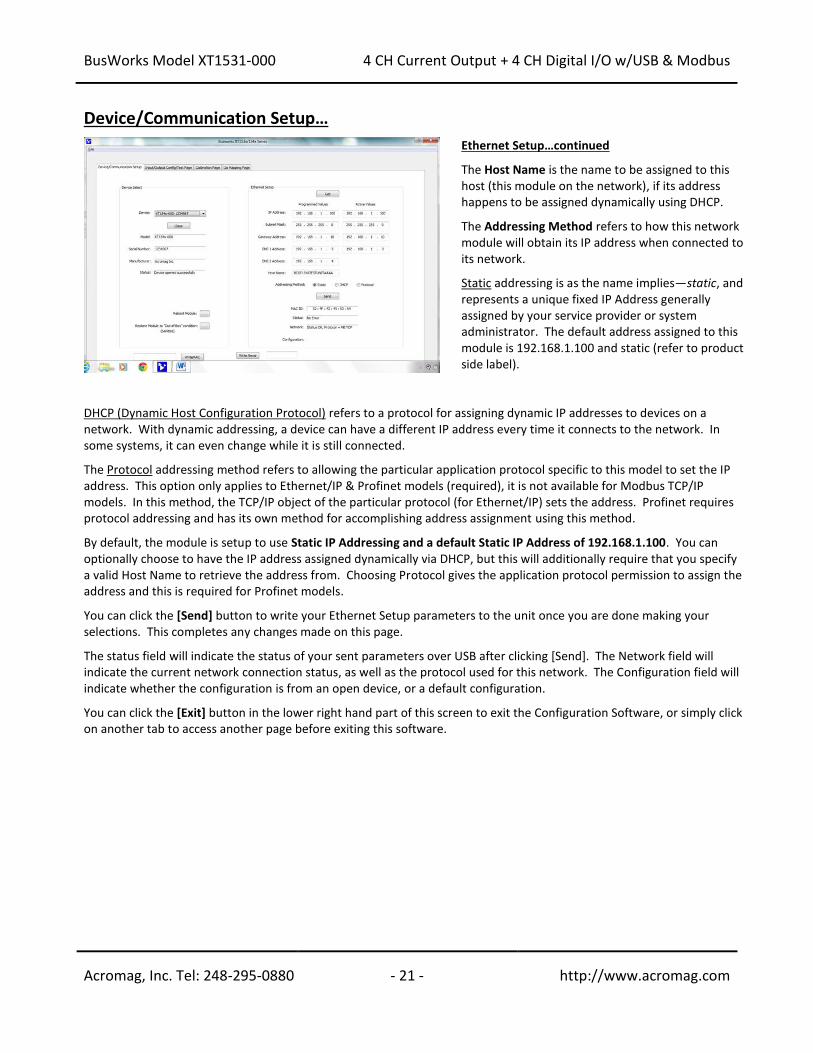
Ethernet Setup…continued The Host Name is the name to be assigned to this host (this module on the network), if its address happens to be assigned dynamically using DHCP. The Addressing Method refers to how this network module will obtain its IP address when connected to its network. Static addressing is as the name implies—static, and represents a unique fixed IP Address generally assigned by your service provider or system administrator. The default address assigned to this module is 192.168.1.100 and static (refer to product side label).
DHCP (Dynamic Host Configuration Protocol) refers to a protocol for assigning dynamic IP addresses to devices on a network. With dynamic addressing, a device can have a different IP address every time it connects to the network. In some systems, it can even change while it is still connected. The Protocol addressing method refers to allowing the particular application protocol specific to this model to set the IP address. This option only applies to Ethernet/IP & Profinet models (required), it is not available for Modbus TCP/IP models. In this method, the TCP/IP object of the particular protocol (for Ethernet/IP) sets the address. Profinet requires protocol addressing and has its own method for accomplishing address assignment using this method. By default, the module is setup to use Static IP Addressing and a default Static IP Address of 192.168.1.100. You can optionally choose to have the IP address assigned dynamically via DHCP, but this will additionally require that you specify a valid Host Name to retrieve the address from. Choosing Protocol gives the application protocol permission to assign the address and this is required for Profinet models. You can click the [Send] button to write your Ethernet Setup parameters to the unit once you are done making your selections. This completes any changes made on this page. The status field will indicate the status of your sent parameters over USB after clicking [Send]. The Network field will indicate the current network connection status, as well as the protocol used for this network. The Configuration field will indicate whether the configuration is from an open device, or a default configuration. You can click the [Exit] button in the lower right hand part of this screen to exit the Configuration Software, or simply click on another tab to access another page before exiting this software.
BusWorks Model XT1531-000
4 CH Current Output + 4 CH Digital I/O w/USB & Modbus
Acromag, Inc. Tel: 248-295-0880 - 22 - http://www.acromag.com
- 22 - http://www.acromag.com
I/O Config/Test Page
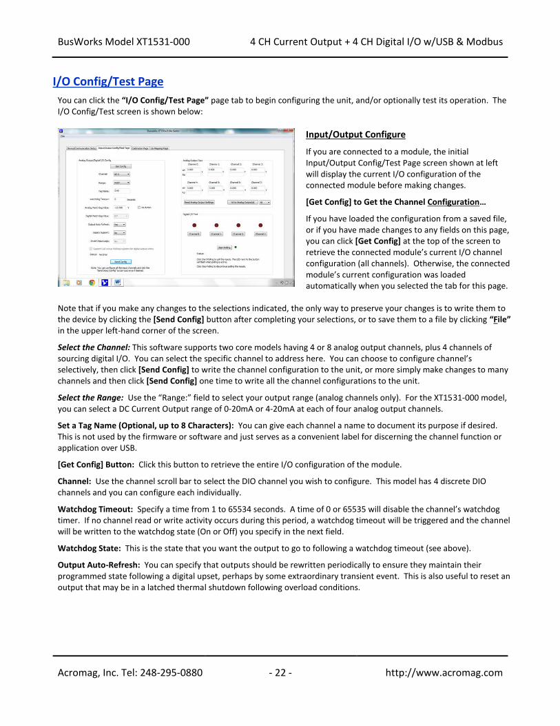
You can click the “I/O Config/Test Page” page tab to begin configuring the unit, and/or optionally test its operation. The I/O Config/Test screen is shown below:
Input/Output Configure If you are connected to a module, the initial Input/Output Config/Test Page screen shown at left will display the current I/O configuration of the connected module before making changes. [Get Config] to Get the Channel Configuration… If you have loaded the configuration from a saved file, or if you have made changes to any fields on this page, you can click [Get Config] at the top of the screen to retrieve the connected module’s current I/O channel configuration (all channels). Otherwise, the connected module’s current configuration was loaded automatically when you selected the tab for this page.
Note that if you make any changes to the selections indicated, the only way to preserve your changes is to write them to the device by clicking the [Send Config] button after completing your selections, or to save them to a file by clicking “File” in the upper left-hand corner of the screen. Select the Channel: This software supports two core models having 4 or 8 analog output channels, plus 4 channels of sourcing digital I/O. You can select the specific channel to address here. You can choose to configure channel’s selectively, then click [Send Config] to write the channel configuration to the unit, or more simply make changes to many channels and then click [Send Config] one time to write all the channel configurations to the unit. Select the Range: Use the “Range:” field to select your output range (analog channels only). For the XT1531-000 model, you can select a DC Current Output range of 0-20mA or 4-20mA at each of four analog output channels. Set a Tag Name (Optional, up to 8 Characters): You can give each channel a name to document its purpose if desired. This is not used by the firmware or software and just serves as a convenient label for discerning the channel function or application over USB. [Get Config] Button: Click this button to retrieve the entire I/O configuration of the module. Channel: Use the channel scroll bar to select the DIO channel you wish to configure. This model has 4 discrete DIO channels and you can configure each individually. Watchdog Timeout: Specify a time from 1 to 65534 seconds. A time of 0 or 65535 will disable the channel’s watchdog timer. If no channel read or write activity occurs during this period, a watchdog timeout will be triggered and the channel will be written to the watchdog state (On or Off) you specify in the next field. Watchdog State: This is the state that you want the output to go to following a watchdog timeout (see above). Output Auto-Refresh: You can specify that outputs should be rewritten periodically to ensure they maintain their programmed state following a digital upset, perhaps by some extraordinary transient event. This is also useful to reset an output that may be in a latched thermal shutdown following overload conditions.
BusWorks Model XT1531-000
4 CH Current Output + 4 CH Digital I/O w/USB & Modbus
Acromag, Inc. Tel: 248-295-0880 - 23 - http://www.acromag.com
- 23 - http://www.acromag.com
I/O Config/Test…
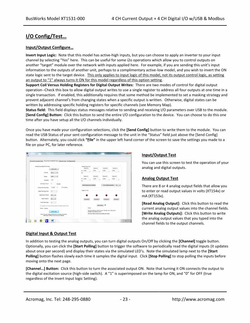
Input/Output Configure… Invert Input Logic: Note that this model has active-high inputs, but you can choose to apply an inverter to your input channel by selecting “Yes” here. This can be useful for some i2o operations which allow you to control outputs on another “target” module over the network with inputs applied here. For example, if you are sending this unit’s input information to the outputs of another unit, perhaps to a complimentary active-low model, and you wish to invert the ON state logic sent to the target device. This only applies to input logic of this model, not its output control logic, as setting an output to “1” always turns it ON for this model regardless of this option setting. Support Coil Versus Holding Registers for Digital Output Writes: There are two modes of control for digital output operation--Check this box to allow digital output writes to use a single register to address all four outputs at one time in a single transaction. If enabled, this additionally requires that some method be implemented to set a masking strategy and prevent adjacent channel’s from changing states when a specific output is written. Otherwise, digital states can be written by addressing specific holding registers for specific channels (see Memory Map). Status field: This field displays status messages relative to sending and receiving I/O parameters over USB to the module. [Send Config] Button: Click this button to send the entire I/O configuration to the device. You can choose to do this one time after you have setup all the I/O channels individually. Once you have made your configuration selections, click the [Send Config] button to write them to the module. You can read the USB Status of your sent configuration message to the unit in the “Status” field just above the [Send Config] button. Alternately, you could click “File” in the upper left hand corner of the screen to save the settings you made to a file on your PC, for later reference.
Input/Output Test You can use this screen to test the operation of your analog and digital outputs.
Analog Output Test There are 8 or 4 analog output fields that allow you to enter or read output values in volts (XT154x) or mA (XT153x). [Read Analog Output]: Click this button to read the current analog output values into the channel fields. [Write Analog Outputs]: Click this button to write the analog output values that you typed into the channel fields to the output channels.
Digital Input & Output Test In addition to testing the analog outputs, you can turn digital outputs On/Off by clicking the [Channel] toggle button. Optionally, you can click the [Start Polling] button to trigger the software to periodically read the digital inputs (it updates about once per second) and display their states via the simulated LED’s. Note the simulated lamp next to the [Start Polling] button flashes slowly each time it samples the digital input. Click [Stop Polling] to stop polling the inputs before moving onto the next page. [Channel…] Button: Click this button to turn the associated output ON. Note that turning it ON connects the output to the digital excitation source (high-side switch). A “1” is superimposed on the lamp for ON, and “0” for OFF (true regardless of the Invert Input logic Setting).
BusWorks Model XT1531-000
4 CH Current Output + 4 CH Digital I/O w/USB & Modbus
Acromag, Inc. Tel: 248-295-0880 - 24 - http://www.acromag.com
- 24 - http://www.acromag.com
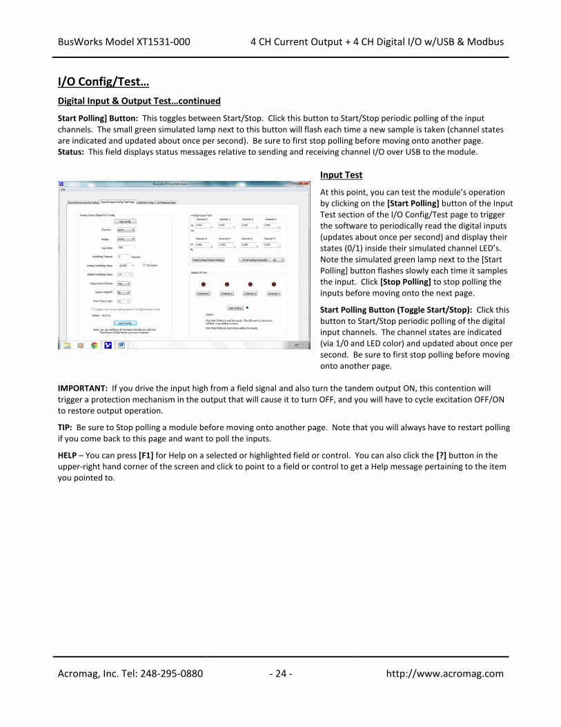
I/O Config/Test… Digital Input & Output Test…continued Start Polling] Button: This toggles between Start/Stop. Click this button to Start/Stop periodic polling of the input channels. The small green simulated lamp next to this button will flash each time a new sample is taken (channel states are indicated and updated about once per second). Be sure to first stop polling before moving onto another page. Status: This field displays status messages relative to sending and receiving channel I/O over USB to the module.
Input Test At this point, you can test the module’s operation by clicking on the [Start Polling] button of the Input Test section of the I/O Config/Test page to trigger the software to periodically read the digital inputs (updates about once per second) and display their states (0/1) inside their simulated channel LED’s. Note the simulated green lamp next to the [Start Polling] button flashes slowly each time it samples the input. Click [Stop Polling] to stop polling the inputs before moving onto the next page. Start Polling Button (Toggle Start/Stop): Click this button to Start/Stop periodic polling of the digital input channels. The channel states are indicated (via 1/0 and LED color) and updated about once per second. Be sure to first stop polling before moving onto another page.
IMPORTANT: If you drive the input high from a field signal and also turn the tandem output ON, this contention will trigger a protection mechanism in the output that will cause it to turn OFF, and you will have to cycle excitation OFF/ON to restore output operation. TIP: Be sure to Stop polling a module before moving onto another page. Note that you will always have to restart polling if you come back to this page and want to poll the inputs. HELP – You can press [F1] for Help on a selected or highlighted field or control. You can also click the [?] button in the upper-right hand corner of the screen and click to point to a field or control to get a Help message pertaining to the item you pointed to.
BusWorks Model XT1531-000
4 CH Current Output + 4 CH Digital I/O w/USB & Modbus
Acromag, Inc. Tel: 248-295-0880 - 25 - http://www.acromag.com
- 25 - http://www.acromag.com
Calibration Page
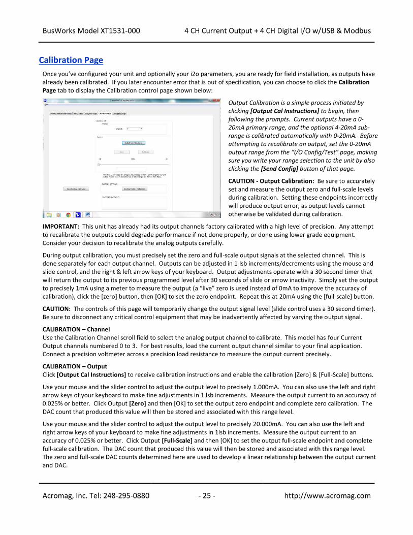
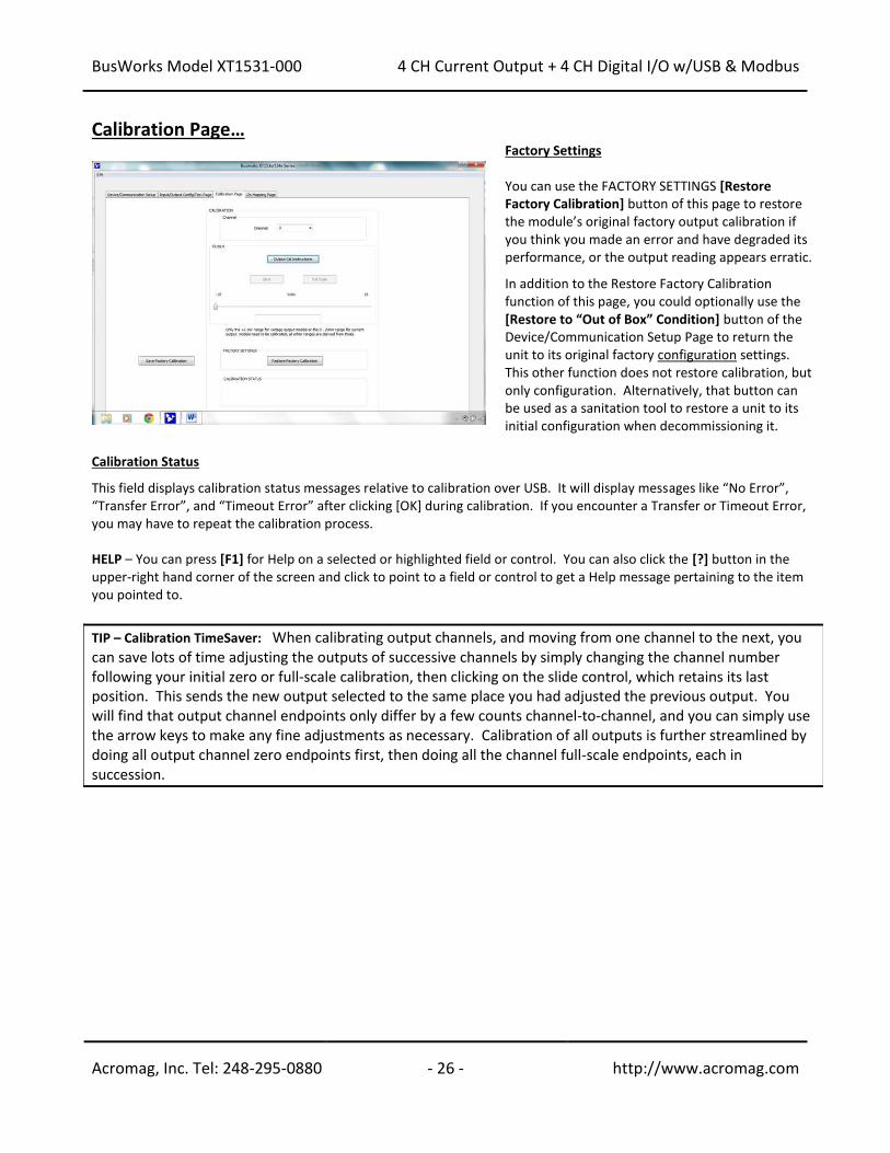
Once you’ve configured your unit and optionally your i2o parameters, you are ready for field installation, as outputs have already been calibrated. If you later encounter error that is out of specification, you can choose to click the Calibration Page tab to display the Calibration control page shown below:
Output Calibration is a simple process initiated by clicking [Output Cal Instructions] to begin, then following the prompts. Current outputs have a 0-20mA primary range, and the optional 4-20mA sub-range is calibrated automatically with 0-20mA. Before attempting to recalibrate an output, set the 0-20mA output range from the “I/O Config/Test” page, making sure you write your range selection to the unit by also clicking the [Send Config] button of that page. CAUTION - Output Calibration: Be sure to accurately set and measure the output zero and full-scale levels during calibration. Setting these endpoints incorrectly will produce output error, as output levels cannot otherwise be validated during calibration.
IMPORTANT: This unit has already had its output channels factory calibrated with a high level of precision. Any attempt to recalibrate the outputs could degrade performance if not done properly, or done using lower grade equipment. Consider your decision to recalibrate the analog outputs carefully. During output calibration, you must precisely set the zero and full-scale output signals at the selected channel. This is done separately for each output channel. Outputs can be adjusted in 1 lsb increments/decrements using the mouse and slide control, and the right & left arrow keys of your keyboard. Output adjustments operate with a 30 second timer that will return the output to its previous programmed level after 30 seconds of slide or arrow inactivity. Simply set the output to precisely 1mA using a meter to measure the output (a “live” zero is used instead of 0mA to improve the accuracy of calibration), click the [zero] button, then [OK] to set the zero endpoint. Repeat this at 20mA using the [full-scale] button. CAUTION: The controls of this page will temporarily change the output signal level (slide control uses a 30 second timer). Be sure to disconnect any critical control equipment that may be inadvertently affected by varying the output signal. CALIBRATION – Channel Use the Calibration Channel scroll field to select the analog output channel to calibrate. This model has four Current Output channels numbered 0 to 3. For best results, load the current output channel similar to your final application. Connect a precision voltmeter across a precision load resistance to measure the output current precisely. CALIBRATION – Output Click [Output Cal Instructions] to receive calibration instructions and enable the calibration [Zero] & [Full-Scale] buttons. Use your mouse and the slider control to adjust the output level to precisely 1.000mA. You can also use the left and right arrow keys of your keyboard to make fine adjustments in 1 lsb increments. Measure the output current to an accuracy of 0.025% or better. Click Output [Zero] and then [OK] to set the output zero endpoint and complete zero calibration. The DAC count that produced this value will then be stored and associated with this range level. Use your mouse and the slider control to adjust the output level to precisely 20.000mA. You can also use the left and right arrow keys of your keyboard to make fine adjustments in 1lsb increments. Measure the output current to an accuracy of 0.025% or better. Click Output [Full-Scale] and then [OK] to set the output full-scale endpoint and complete full-scale calibration. The DAC count that produced this value will then be stored and associated with this range level. The zero and full-scale DAC counts determined here are used to develop a linear relationship between the output current and DAC.
BusWorks Model XT1531-000
4 CH Current Output + 4 CH Digital I/O w/USB & Modbus
Acromag, Inc. Tel: 248-295-0880 - 26 - http://www.acromag.com
- 26 - http://www.acromag.com
Calibration Page…
Factory Settings You can use the FACTORY SETTINGS [Restore Factory Calibration] button of this page to restore the module’s original factory output calibration if you think you made an error and have degraded its performance, or the output reading appears erratic. In addition to the Restore Factory Calibration function of this page, you could optionally use the [Restore to “Out of Box” Condition] button of the Device/Communication Setup Page to return the unit to its original factory configuration settings. This other function does not restore calibration, but only configuration. Alternatively, that button can be used as a sanitation tool to restore a unit to its initial configuration when decommissioning it.
Calibration Status This field displays calibration status messages relative to calibration over USB. It will display messages like “No Error”, “Transfer Error”, and “Timeout Error” after clicking [OK] during calibration. If you encounter a Transfer or Timeout Error, you may have to repeat the calibration process. HELP – You can press [F1] for Help on a selected or highlighted field or control. You can also click the [?] button in the upper-right hand corner of the screen and click to point to a field or control to get a Help message pertaining to the item you pointed to.
TIP – Calibration TimeSaver: When calibrating output channels, and moving from one channel to the next, you can save lots of time adjusting the outputs of successive channels by simply changing the channel number following your initial zero or full-scale calibration, then clicking on the slide control, which retains its last position. This sends the new output selected to the same place you had adjusted the previous output. You will find that output channel endpoints only differ by a few counts channel-to-channel, and you can simply use the arrow keys to make any fine adjustments as necessary. Calibration of all outputs is further streamlined by doing all output channel zero endpoints first, then doing all the channel full-scale endpoints, each in succession.
BusWorks Model XT1531-000
4 CH Current Output + 4 CH Digital I/O w/USB & Modbus
Acromag, Inc. Tel: 248-295-0880 - 27 - http://www.acromag.com
- 27 - http://www.acromag.com
i2o Mapping Page
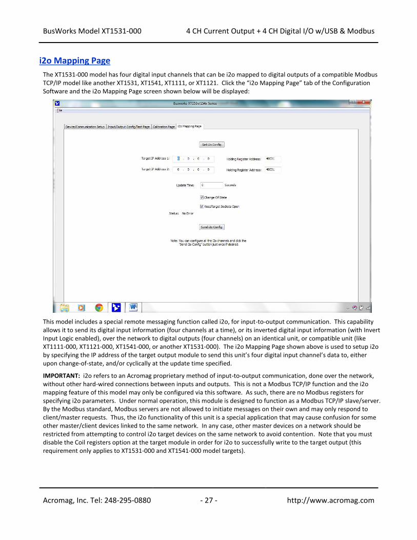
The XT1531-000 model has four digital input channels that can be i2o mapped to digital outputs of a compatible Modbus TCP/IP model like another XT1531, XT1541, XT1111, or XT1121. Click the “i2o Mapping Page” tab of the Configuration Software and the i2o Mapping Page screen shown below will be displayed:
This model includes a special remote messaging function called i2o, for input-to-output communication. This capability allows it to send its digital input information (four channels at a time), or its inverted digital input information (with Invert Input Logic enabled), over the network to digital outputs (four channels) on an identical unit, or compatible unit (like XT1111-000, XT1121-000, XT1541-000, or another XT1531-000). The i2o Mapping Page shown above is used to setup i2o by specifying the IP address of the target output module to send this unit’s four digital input channel’s data to, either upon change-of-state, and/or cyclically at the update time specified. IMPORTANT: i2o refers to an Acromag proprietary method of input-to-output communication, done over the network, without other hard-wired connections between inputs and outputs. This is not a Modbus TCP/IP function and the i2o mapping feature of this model may only be configured via this software. As such, there are no Modbus registers for specifying i2o parameters. Under normal operation, this module is designed to function as a Modbus TCP/IP slave/server. By the Modbus standard, Modbus servers are not allowed to initiate messages on their own and may only respond to client/master requests. Thus, the i2o functionality of this unit is a special application that may cause confusion for some other master/client devices linked to the same network. In any case, other master devices on a network should be restricted from attempting to control i2o target devices on the same network to avoid contention. Note that you must disable the Coil registers option at the target module in order for i2o to successfully write to the target output (this requirement only applies to XT1531-000 and XT1541-000 model targets).
BusWorks Model XT1531-000
4 CH Current Output + 4 CH Digital I/O w/USB & Modbus
Acromag, Inc. Tel: 248-295-0880 - 28 - http://www.acromag.com
- 28 - http://www.acromag.com
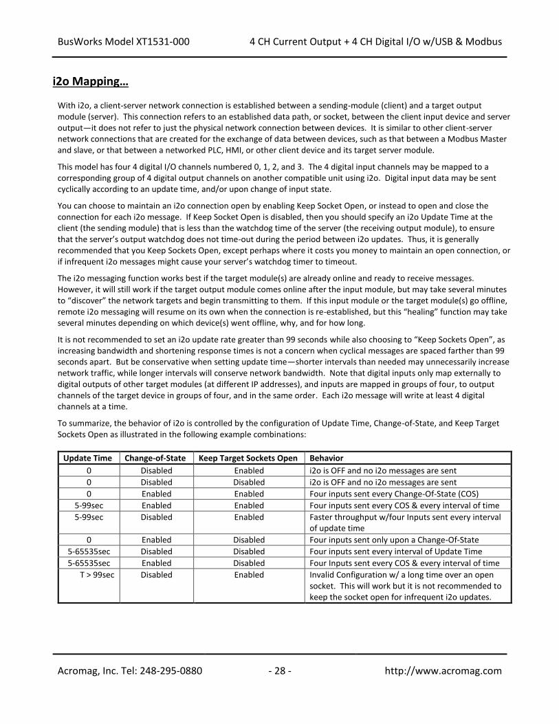
i2o Mapping… With i2o, a client-server network connection is established between a sending-module (client) and a target output module (server). This connection refers to an established data path, or socket, between the client input device and server output—it does not refer to just the physical network connection between devices. It is similar to other client-server network connections that are created for the exchange of data between devices, such as that between a Modbus Master and slave, or that between a networked PLC, HMI, or other client device and its target server module. This model has four 4 digital I/O channels numbered 0, 1, 2, and 3. The 4 digital input channels may be mapped to a corresponding group of 4 digital output channels on another compatible unit using i2o. Digital input data may be sent cyclically according to an update time, and/or upon change of input state. You can choose to maintain an i2o connection open by enabling Keep Socket Open, or instead to open and close the connection for each i2o message. If Keep Socket Open is disabled, then you should specify an i2o Update Time at the client (the sending module) that is less than the watchdog time of the server (the receiving output module), to ensure that the server’s output watchdog does not time-out during the period between i2o updates. Thus, it is generally recommended that you Keep Sockets Open, except perhaps where it costs you money to maintain an open connection, or if infrequent i2o messages might cause your server’s watchdog timer to timeout. The i2o messaging function works best if the target module(s) are already online and ready to receive messages. However, it will still work if the target output module comes online after the input module, but may take several minutes to “discover” the network targets and begin transmitting to them. If this input module or the target module(s) go offline, remote i2o messaging will resume on its own when the connection is re-established, but this “healing” function may take several minutes depending on which device(s) went offline, why, and for how long. It is not recommended to set an i2o update rate greater than 99 seconds while also choosing to “Keep Sockets Open”, as increasing bandwidth and shortening response times is not a concern when cyclical messages are spaced farther than 99 seconds apart. But be conservative when setting update time—shorter intervals than needed may unnecessarily increase network traffic, while longer intervals will conserve network bandwidth. Note that digital inputs only map externally to digital outputs of other target modules (at different IP addresses), and inputs are mapped in groups of four, to output channels of the target device in groups of four, and in the same order. Each i2o message will write at least 4 digital channels at a time. To summarize, the behavior of i2o is controlled by the configuration of Update Time, Change-of-State, and Keep Target Sockets Open as illustrated in the following example combinations:
Update Time Change-of-State Keep Target Sockets Open Behavior
0 Disabled Enabled i2o is OFF and no i2o messages are sent
0 Disabled Disabled i2o is OFF and no i2o messages are sent
0 Enabled Enabled Four inputs sent every Change-Of-State (COS)
5-99sec Enabled Enabled Four inputs sent every COS & every interval of time
5-99sec Disabled Enabled Faster throughput w/four Inputs sent every interval of update time
0 Enabled Disabled Four inputs sent only upon a Change-Of-State
5-65535sec Disabled Disabled Four inputs sent every interval of Update Time
5-65535sec Enabled Disabled Four Inputs sent every COS & every interval of time
T > 99sec Disabled Enabled Invalid Configuration w/ a long time over an open socket. This will work but it is not recommended to keep the socket open for infrequent i2o updates.
BusWorks Model XT1531-000
4 CH Current Output + 4 CH Digital I/O w/USB & Modbus
Acromag, Inc. Tel: 248-295-0880 - 29 - http://www.acromag.com
- 29 - http://www.acromag.com
i2o Mapping… The four input channels of this device may be mapped to four output channels at another Acromag digital I/O module at one or two different IP addresses. Subsequent messages will be sent at a periodic rate specified by update time. Note that the target output channels may still be controlled independently via the network, but their state will be overwritten by subsequent mapped messages when enabled. It is recommended that you do not control the i2o targeted mapped output channels directly, as this could create contention with i2o control. You cannot use the USB software to control the state of outputs that are i2o targets. [Get i2o Config] Button: Click this button to retrieve the current i2o configuration from the unit. See the Status field for the status of this operation. Target IP Address 1 & Target IP Address 2: This is the IP Address of a group of 4 output channels at one or two target output modules (other compatible modules on the network). The four digital inputs of this unit can only be mapped to a group of four digital outputs (in same order) at one or two target IP addresses. Holding Register Address 1 & 2: This is the Memory Map address of the output channels (4 consecutive digital output channels) at your i2o target to send this units input data to. Update Time Field: Specify a time from 5-65534 seconds between messages. Specify 0 or 65535 to turn i2o messaging OFF (cyclical). If change-of-state is enabled and a time greater than or equal to 5 is specified, your message will be sent both upon change of state and at the update time specified. Change-of-State Checkbox: Set ON to enable output updates on change of input state, and OFF to update cyclically according to the update time. Keep Target Sockets Open Checkbox: Check this box to keep the communication socket of the target device open after sending i2o data to it. Keeping the socket open is helpful to obtain faster throughput, as open and close socket messages are not required for each i2o message, allowing an i2o message to be sent immediately along an already open socket. But you should not keep the socket open if you do not require frequent updates, as it does limit the bandwidth somewhat. So for wireless/cellular systems, or peer-to-peer applications with long intervals between update messages, you may consider unchecking this box. While still possible, do not Keep Sockets Open and set update intervals greater than 99 seconds (infrequent messaging with long i2o intervals does not need to keep the socket open). Status Field (USB): Gives the status of your USB i2o configuration message (i.e. returns the status of the write or read of i2o configuration info only). [Send i2o Config] Button: Click this button to write your i2o configuration to the unit. You may click [Send i2o Config] for each group, one at a time, or you can step through all i20 channels and then click the [Send i2o Config] button one time to write your entire i2o configuration. See the Status field for the status of this operation.
BusWorks Model XT1531-000
4 CH Current Output + 4 CH Digital I/O w/USB & Modbus
Acromag, Inc. Tel: 248-295-0880 - 30 - http://www.acromag.com
- 30 - http://www.acromag.com
Network Home Page After you have configured your unit for network communication via its USB connection, you can identify the unit on the Ethernet network using a web browser directed to its IP address (you set this address on the Device/Communication Setup page of the USB Configuration Software for the unit, the default is 192.168.1.100). This will access the home page of the unit similar to the first screen shown on the following page. You can click the “Communication Parameters” link of the Home Page to access the Ethernet Connection Status page shown in the second screen on the following page, which reviews the unit’s network communication parameters that were set over a USB connection to the device (scroll down this page to view all applicable parameter settings).
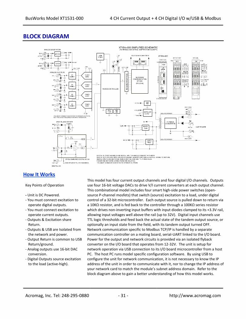
BusWorks Model XT1531-000
4 CH Current Output + 4 CH Digital I/O w/USB & Modbus
Acromag, Inc. Tel: 248-295-0880 - 31 - http://www.acromag.com
- 31 - http://www.acromag.com
BLOCK DIAGRAM
How It Works Key Points of Operation - Unit is DC Powered. - You must connect excitation to
operate digital outputs. - You must connect excitation to
operate current outputs. - Outputs & Excitation share
Return. - Outputs & USB are Isolated from
the network and power. - Output Return is common to USB
Return/ground. - Analog outputs use 16-bit DAC
conversion. - Digital Outputs source excitation
to the load (active-high).
This model has four current output channels and four digital I/O channels. Outputs use four 16-bit voltage DACs to drive V/I current converters at each output channel. This combinational model includes four smart high-side power switches (open-source P-channel mosfets) that switch (source) excitation to a load, under digital control of a 32-bit microcontroller. Each output source is pulled down to return via a 10KΩ resistor, and is fed back to the controller through a 100KΩ series resistor which drives non-inverting input buffers with input diodes clamped to its +3.3V rail, allowing input voltages well above the rail (up to 32V). Digital input channels use TTL logic thresholds and feed back the actual state of the tandem output source, or optionally an input state from the field, with its tandem output turned OFF. Network communication specific to Modbus TCP/IP is handled by a separate communication controller on a mating board, serial-UART linked to the I/O board. Power for the output and network circuits is provided via an isolated flyback converter on the I/O board that operates from 12-32V. The unit is setup for network operation via USB connection to its I/O board microcontroller from a host PC. The host PC runs model specific configuration software. By using USB to configure the unit for network communication, it is not necessary to know the IP address of the unit in order to communicate with it, nor to change the IP address of your network card to match the module’s subnet address domain. Refer to the block diagram above to gain a better understanding of how this model works.
BusWorks Model XT1531-000
4 CH Current Output + 4 CH Digital I/O w/USB & Modbus
Acromag, Inc. Tel: 248-295-0880 - 32 - http://www.acromag.com
- 32 - http://www.acromag.com
How it Works… The outputs and excitation and USB, the network, and power circuits are isolated from each other. The USB port ground is common to the output circuit return. The USB port ground of most PC’s is also common to the USB cable shield and earth ground. I/O could otherwise be grounded or ungrounded. For this reason, it is recommended that USB signals be isolated when connected to a PC to prevent a ground loop from occurring between the PC earth ground and a grounded I/O signal, which could have the negative effect of driving digital upset or noise for severe ground loop currents.
About Modbus TCP/IP IP (Internet Protocol) is the method by which data is sent from one computer (host)
to another computer (host) on the network (Internet). In the Open Systems Interconnection (OSI) communication model, IP is in layer 3, the Networking Layer. Every computer or host on the Internet has an IP address that uniquely defines it from all the other computers or hosts on the Internet. IP is a connectionless protocol, which means that there is no continuing connection between end points (hosts) that are communicating. That is, each packet that travels across the Internet is treated as an independent unit of data without any relationship to any other unit of data. Messages sent over the internet can be quite lengthy and are often divided into a number of smaller data packets. Every data packet contains both the sender’s Internet address and the receiver’s address. Each packet can, if necessary be sent by a different route across the Internet. As a result, the packets can arrive at their destination address in a different order. While the IP delivers the data packets, it is up to another protocol, the TCP (Transmission Control Protocol) to make sure that the packets are reassembled in the correct order. So we see that the function of TCP is to ensure that all packets of data are received correctly, while IP makes sure that messages are correctly addressed and routed. Thus, TCP/IP refers to the functional combination of the Transmission Control Protocol and the Internet Protocol used to accomplish this and it allows blocks of binary data (packets) to be exchanged between computers, and reassembled in the proper order at their destination. TCP/IP is used world-wide and forms the foundation for the World Wide Web. But the TCP/IP combination does not define what the data means or how the data is to be interpreted, it is merely a transport protocol. For this module, Modbus is the application protocol and operates on the data, defining its meaning and purpose. You can find more information on Modbus TCP/IP by visiting our web site and down-loading whitepaper 8500-765, Introduction To Modbus TCP/IP. In contrast to the Transport Protocol TCP/IP, Modbus is an application protocol. It defines rules for organizing and interpreting data and is essentially a messaging structure that is independent of the underlying physical layer. It is freely available and accessible to anyone, easy to understand, and widely supported by many manufacturers. The combination of both of these protocols forms Modbus TCP/IP. Modbus (application protocol) uses TCP/IP (transport protocol) over the Internet to carry the data of the Modbus message structure between devices. That is, Modbus TCP/IP combines a physical network (Ethernet), with a networking standard (TCP/IP), and a standard method of representing data (Modbus). Then, a Modbus TCP/IP message is simply a Modbus communication encapsulated in an Ethernet TCP/IP wrapper.
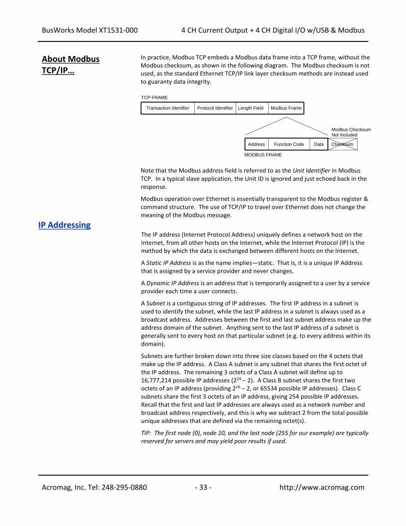
BusWorks Model XT1531-000
4 CH Current Output + 4 CH Digital I/O w/USB & Modbus
Acromag, Inc. Tel: 248-295-0880 - 33 - http://www.acromag.com
- 33 - http://www.acromag.com
About Modbus TCP/IP…
In practice, Modbus TCP embeds a Modbus data frame into a TCP frame, without the Modbus checksum, as shown in the following diagram. The Modbus checksum is not used, as the standard Ethernet TCP/IP link layer checksum methods are instead used to guaranty data integrity.
Note that the Modbus address field is referred to as the Unit Identifier in Modbus TCP. In a typical slave application, the Unit ID is ignored and just echoed back in the response. Modbus operation over Ethernet is essentially transparent to the Modbus register & command structure. The use of TCP/IP to travel over Ethernet does not change the meaning of the Modbus message.
IP Addressing The IP address (Internet Protocol Address) uniquely defines a network host on the
Internet, from all other hosts on the Internet, while the Internet Protocol (IP) is the method by which the data is exchanged between different hosts on the Internet. A Static IP Address is as the name implies—static. That is, it is a unique IP Address that is assigned by a service provider and never changes. A Dynamic IP Address is an address that is temporarily assigned to a user by a service provider each time a user connects. A Subnet is a contiguous string of IP addresses. The first IP address in a subnet is used to identify the subnet, while the last IP address in a subnet is always used as a broadcast address. Addresses between the first and last subnet address make up the address domain of the subnet. Anything sent to the last IP address of a subnet is generally sent to every host on that particular subnet (e.g. to every address within its domain). Subnets are further broken down into three size classes based on the 4 octets that make up the IP address. A Class A subnet is any subnet that shares the first octet of the IP address. The remaining 3 octets of a Class A subnet will define up to 16,777,214 possible IP addresses (224 – 2). A Class B subnet shares the first two octets of an IP address (providing 216 – 2, or 65534 possible IP addresses). Class C subnets share the first 3 octets of an IP address, giving 254 possible IP addresses. Recall that the first and last IP addresses are always used as a network number and broadcast address respectively, and this is why we subtract 2 from the total possible unique addresses that are defined via the remaining octet(s). TIP: The first node (0), node 10, and the last node (255 for our example) are typically reserved for servers and may yield poor results if used.
Checksum
TCP FRAME
MODBUS FRAME
Transaction Identifier Modbus FrameLength FieldProtocol Identifier
DataAddress Function Code
Modbus ChecksumNot Included
BusWorks Model XT1531-000
4 CH Current Output + 4 CH Digital I/O w/USB & Modbus
Acromag, Inc. Tel: 248-295-0880 - 34 - http://www.acromag.com
- 34 - http://www.acromag.com
IP Addressing… For our example, the default IP address of this module is 192.168.1.100. If we assume that this is a Class C network address (based on a default Class C subnet mask of 255.255.255.0), then the first three numbers represent this Class C network (or subnet) at address 192.168.1.0, the last number identifies a unique host/node on this network (node 100) at address 192.168.1.100. The Subnet Mask is used to determine which subnet an IP address belongs to. The use of a subnet mask allows the network administrator to further divide the host part of this address into two or more subnets. The subnet mask flags the network address portion of the IP address, plus the bits of the host part that are used for identifying the sub-network. By convention, the bits of the mask that correspond to the sub-network address are all set to 1’s (it would also work if the bits were set exactly as in the network address). It’s called a mask because it can be used to identify the unique subnet to which an IP address belongs to by performing a bitwise AND operation between the mask itself, and the IP address, with the result being the subnetwork address, and the remaining bits the host or node address. For our Example, if we wish to further divide this network into 14 subnets, then the first 4 bits of the host address will be required to identify the subnetwork (0110), then we would use “11111111.11111111.11111111. 11110000” as our subnet mask. This would effectively subdivide our Class C network into 14 subnetworks of up to 14 possible nodes each. With respect to the default settings of this module: Subnet Mask 255.255.255.0 (11111111.11111111.11111111.00000000) IP Address: 192.168.1.100 (10000000.00000001.00000001.01100100) Subnet Address: 128.1.1.0 (1000000.00000001.00000001.00000000) The subnetwork address of 128.1.1.0 has 254 possible unique node addresses (we are using node 100 of 254 possible as our default). Nodes 0, 10, and 255 are typically reserved for servers and may yield poor results if used.
Dynamic Host Configuration Protocol (DHCP)
DHCP refers to the Dynamic Host Configuration Protocol and is a method used to assign unique temporary numeric IP addresses as required. A DHCP server maintains a pool of shared IP addresses which are dynamically assigned and recycled. When a DHCP device wants to use a TCP/IP application, it must request an IP address from the DHCP server. The DHCP server will check the shared supply addresses, and if all addresses are in use, the server will send a busy signal to the client which signals it to try again later. Only static IP addresses will ensure a connection every time, while dynamic addresses do not.
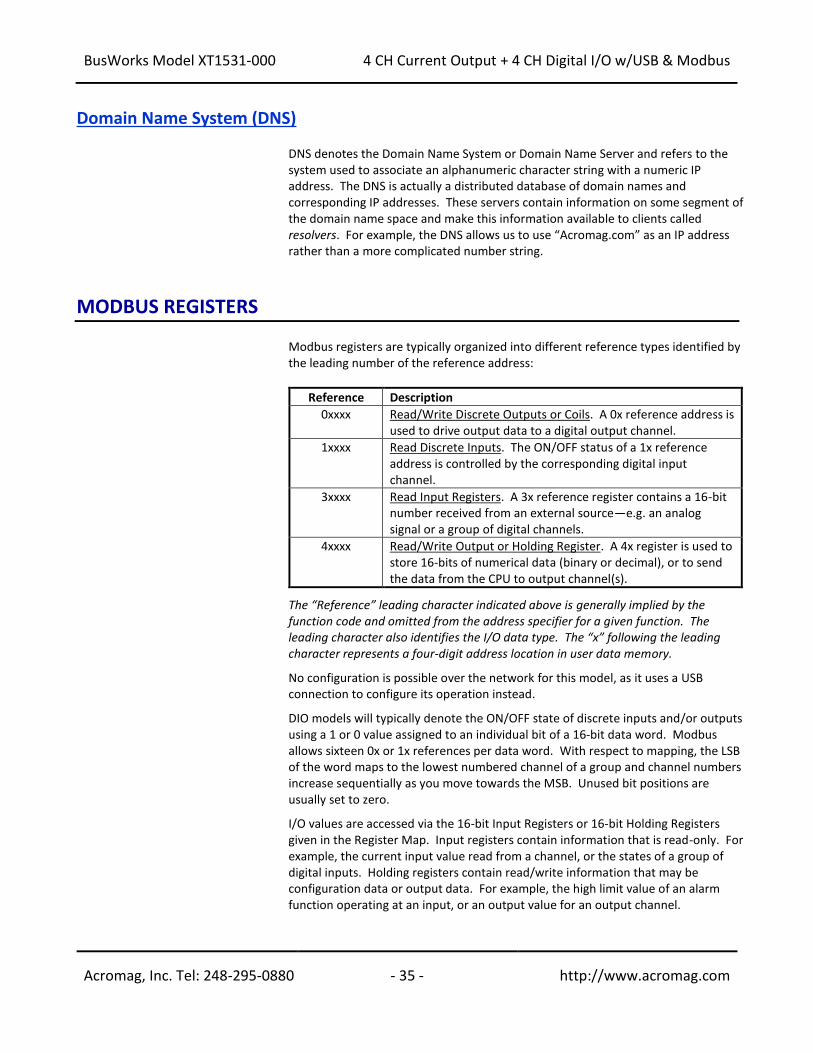
BusWorks Model XT1531-000
4 CH Current Output + 4 CH Digital I/O w/USB & Modbus
Acromag, Inc. Tel: 248-295-0880 - 35 - http://www.acromag.com
- 35 - http://www.acromag.com
Domain Name System (DNS)
DNS denotes the Domain Name System or Domain Name Server and refers to the system used to associate an alphanumeric character string with a numeric IP address. The DNS is actually a distributed database of domain names and corresponding IP addresses. These servers contain information on some segment of the domain name space and make this information available to clients called resolvers. For example, the DNS allows us to use “Acromag.com” as an IP address rather than a more complicated number string.
MODBUS REGISTERS
Modbus registers are typically organized into different reference types identified by the leading number of the reference address:
Reference Description
0xxxx Read/Write Discrete Outputs or Coils. A 0x reference address is used to drive output data to a digital output channel.
1xxxx Read Discrete Inputs. The ON/OFF status of a 1x reference address is controlled by the corresponding digital input channel.
3xxxx Read Input Registers. A 3x reference register contains a 16-bit number received from an external source—e.g. an analog signal or a group of digital channels.
4xxxx Read/Write Output or Holding Register. A 4x register is used to store 16-bits of numerical data (binary or decimal), or to send the data from the CPU to output channel(s).
The “Reference” leading character indicated above is generally implied by the function code and omitted from the address specifier for a given function. The leading character also identifies the I/O data type. The “x” following the leading character represents a four-digit address location in user data memory. No configuration is possible over the network for this model, as it uses a USB connection to configure its operation instead. DIO models will typically denote the ON/OFF state of discrete inputs and/or outputs using a 1 or 0 value assigned to an individual bit of a 16-bit data word. Modbus allows sixteen 0x or 1x references per data word. With respect to mapping, the LSB of the word maps to the lowest numbered channel of a group and channel numbers increase sequentially as you move towards the MSB. Unused bit positions are usually set to zero. I/O values are accessed via the 16-bit Input Registers or 16-bit Holding Registers given in the Register Map. Input registers contain information that is read-only. For example, the current input value read from a channel, or the states of a group of digital inputs. Holding registers contain read/write information that may be configuration data or output data. For example, the high limit value of an alarm function operating at an input, or an output value for an output channel.
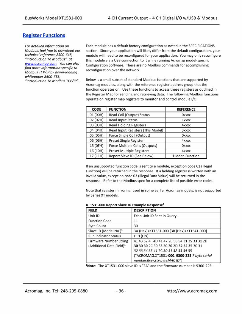
BusWorks Model XT1531-000
4 CH Current Output + 4 CH Digital I/O w/USB & Modbus
Acromag, Inc. Tel: 248-295-0880 - 36 - http://www.acromag.com
- 36 - http://www.acromag.com
Register Functions For detailed information on Modbus, feel free to download our technical reference 8500-648, “Introduction To Modbus”, at www.acromag.com. You can also find more information specific to Modbus TCP/IP by down-loading whitepaper 8500-765, “Introduction To Modbus TCP/IP”.
Each module has a default factory configuration as noted in the SPECIFICATIONS section. Since your application will likely differ from the default configuration, your module will need to be reconfigured for your application. You may only reconfigure this module via a USB connection to it while running Acromag model-specific Configuration Software. There are no Modbus commands for accomplishing reconfiguration over the network. Below is a small subset of standard Modbus functions that are supported by Acromag modules, along with the reference register address group that the function operates on. Use these functions to access these registers as outlined in the Register Map for sending and retrieving data. The following Modbus functions operate on register map registers to monitor and control module I/O:
CODE FUNCTION REFERENCE
01 (00H) Read Coil (Output) Status 0xxxx
02 (02H) Read Input Status 1xxxx
03 (03H) Read Holding Registers 4xxxx
04 (04H) Read Input Registers (This Model) 3xxxx
05 (05H) Force Single Coil (Output) 0xxxx
06 (06H) Preset Single Register 4xxxx
15 (0FH) Force Multiple Coils (Outputs) 0xxxx
16 (10H) Preset Multiple Registers 4xxxx
17 (11H) Report Slave ID (See Below) Hidden Function
If an unsupported function code is sent to a module, exception code 01 (Illegal Function) will be returned in the response. If a holding register is written with an invalid value, exception code 03 (Illegal Data Value) will be returned in the response. Refer to the Modbus spec for a complete list of possible error codes. Note that register mirroring, used in some earlier Acromag models, is not supported by Series XT models. XT1531-000 Report Slave ID Example Response1
FIELD DESCRIPTION
Unit ID Echo Unit ID Sent In Query
Function Code 11
Byte Count 30
Slave ID (Model No.)1 3A (Hex)=XT1531-000 [3B (Hex)=XT1541-000]
Run Indicator Status FFH (ON)
Firmware Number String (Additional Data Field)1
41 43 52 4F 4D 41 47 2C 58 54 31 35 33 31 2D 30 30 30 2C 39 33 30 30 2D 32 32 35 30 31 32 33 34 35 41 2C 30 31 32 33 34 35 (“ACROMAG,XT1531-000, 9300-225 7 byte serial number&rev,six-byteMAC ID”)
1Note: The XT1531-000 slave ID is “3A” and the firmware number is 9300-225.

BusWorks Model XT1531-000
4 CH Current Output + 4 CH Digital I/O w/USB & Modbus
Acromag, Inc. Tel: 248-295-0880 - 37 - http://www.acromag.com
- 37 - http://www.acromag.com
Data Types DATA TYPES AND DESCRIPTIONS USED BY THIS MODEL
Discrete/Digital Data
Applies for R/W to Holding Registers, not Coil Registers, which are accessed using coil register commands that do not operate directly on the register contents. A discrete value is generally indicated by a single bit of a 16-bit word. The bit number (position) may correspond to the discrete channel number. For digital outputs of this model, a set (1) bit means the corresponding output is sourcing excitation to the output or ON, and a clear (0) bit means the output is open or OFF. For digital inputs, a value of 1 means the input is ON (Active-high above the TTL threshold or greater than 2.0V), while a value of 0 specifies the input is OFF or in its low state (below the TTL threshold or less than 0.8V). This assumes that the Input Logic Invert function is set to “No” or disabled.
Analog Data
A 16-bit signed integer with a maximum possible range of -32768 to +32767. The unipolar analog output ranges of this model are normalized to 0-30000 or 0-20000 (w/legacy support selected), which represents 0-100% of the pre-defined range. For example 0% and +100% are represented by decimal values 0, and 30000, respectively, or 0 and 20000 with Legacy Support enabled. The full possible range is decimal 0-109.2%, or 0-32768 decimal. Thus, for this model, 20mA is driven with a raw register DAC count of 0 to 32768*(0.020*249/5.5254) =29533. A 4mA range zero would correspond to 32768*(0.004*249/5.5254V) =5907.
Register Map This model has two different register maps, depending on the mode of digital output access you select. That is, you can enable Coil Registers and use those registers to control digital I/O discretely, or you can disable Coil Registers and use a Holding Register instead to control digital outputs as a group. Modbus functions operate on the registers noted using the data types above (except for the Reset Slave and Report Slave ID functions). The memory maps for this model covers reading analog and digital input data, and writing analog and digital output data. There are no registers for setting any configuration variables, as this model is only configured via USB using its Configuration Software running on a Windows based Personal Computer, prior to connecting to the network. IMPORTANT: If this module is being used as an i2o target, support for Coil Registers must be disabled, or i2o will not work (i2o writes are always written 4 channels at a time and always use a Holding Register to control the digital outputs simultaneously). The “Support Coil versus Holding Register for Digital Output Writes” option is a global setting that applies to all digital outputs of a module. It is enabled or disabled from the Analog Output/Digital I/O Configuration page of the USB Configuration Software for this model.
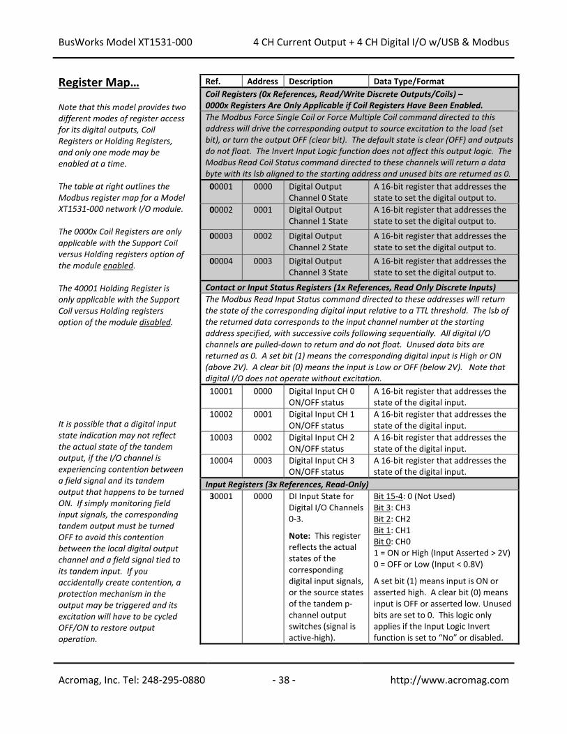
BusWorks Model XT1531-000
4 CH Current Output + 4 CH Digital I/O w/USB & Modbus
Acromag, Inc. Tel: 248-295-0880 - 38 - http://www.acromag.com
- 38 - http://www.acromag.com
Register Map… Note that this model provides two different modes of register access for its digital outputs, Coil Registers or Holding Registers, and only one mode may be enabled at a time. The table at right outlines the Modbus register map for a Model XT1531-000 network I/O module. The 0000x Coil Registers are only applicable with the Support Coil versus Holding registers option of the module enabled. The 40001 Holding Register is only applicable with the Support Coil versus Holding registers option of the module disabled. It is possible that a digital input state indication may not reflect the actual state of the tandem output, if the I/O channel is experiencing contention between a field signal and its tandem output that happens to be turned ON. If simply monitoring field input signals, the corresponding tandem output must be turned OFF to avoid this contention between the local digital output channel and a field signal tied to its tandem input. If you accidentally create contention, a protection mechanism in the output may be triggered and its excitation will have to be cycled OFF/ON to restore output operation.
Ref. Address Description Data Type/Format
Coil Registers (0x References, Read/Write Discrete Outputs/Coils) – 0000x Registers Are Only Applicable if Coil Registers Have Been Enabled.
The Modbus Force Single Coil or Force Multiple Coil command directed to this address will drive the corresponding output to source excitation to the load (set bit), or turn the output OFF (clear bit). The default state is clear (OFF) and outputs do not float. The Invert Input Logic function does not affect this output logic. The Modbus Read Coil Status command directed to these channels will return a data byte with its lsb aligned to the starting address and unused bits are returned as 0.
00001 0000 Digital Output Channel 0 State
A 16-bit register that addresses the state to set the digital output to.
00002 0001 Digital Output Channel 1 State
A 16-bit register that addresses the state to set the digital output to.
00003 0002 Digital Output Channel 2 State
A 16-bit register that addresses the state to set the digital output to.
00004 0003 Digital Output Channel 3 State
A 16-bit register that addresses the state to set the digital output to.
Contact or Input Status Registers (1x References, Read Only Discrete Inputs)
The Modbus Read Input Status command directed to these addresses will return the state of the corresponding digital input relative to a TTL threshold. The lsb of the returned data corresponds to the input channel number at the starting address specified, with successive coils following sequentially. All digital I/O channels are pulled-down to return and do not float. Unused data bits are returned as 0. A set bit (1) means the corresponding digital input is High or ON (above 2V). A clear bit (0) means the input is Low or OFF (below 2V). Note that digital I/O does not operate without excitation.
10001 0000 Digital Input CH 0 ON/OFF status
A 16-bit register that addresses the state of the digital input.
10002 0001 Digital Input CH 1 ON/OFF status
A 16-bit register that addresses the state of the digital input.
10003 0002 Digital Input CH 2 ON/OFF status
A 16-bit register that addresses the state of the digital input.
10004 0003 Digital Input CH 3 ON/OFF status
A 16-bit register that addresses the state of the digital input.
Input Registers (3x References, Read-Only)
30001 0000 DI Input State for Digital I/O Channels 0-3. Note: This register reflects the actual states of the corresponding digital input signals, or the source states of the tandem p-channel output switches (signal is active-high).
Bit 15-4: 0 (Not Used) Bit 3: CH3 Bit 2: CH2 Bit 1: CH1 Bit 0: CH0 1 = ON or High (Input Asserted > 2V) 0 = OFF or Low (Input < 0.8V) A set bit (1) means input is ON or asserted high. A clear bit (0) means input is OFF or asserted low. Unused bits are set to 0. This logic only applies if the Input Logic Invert function is set to “No” or disabled.
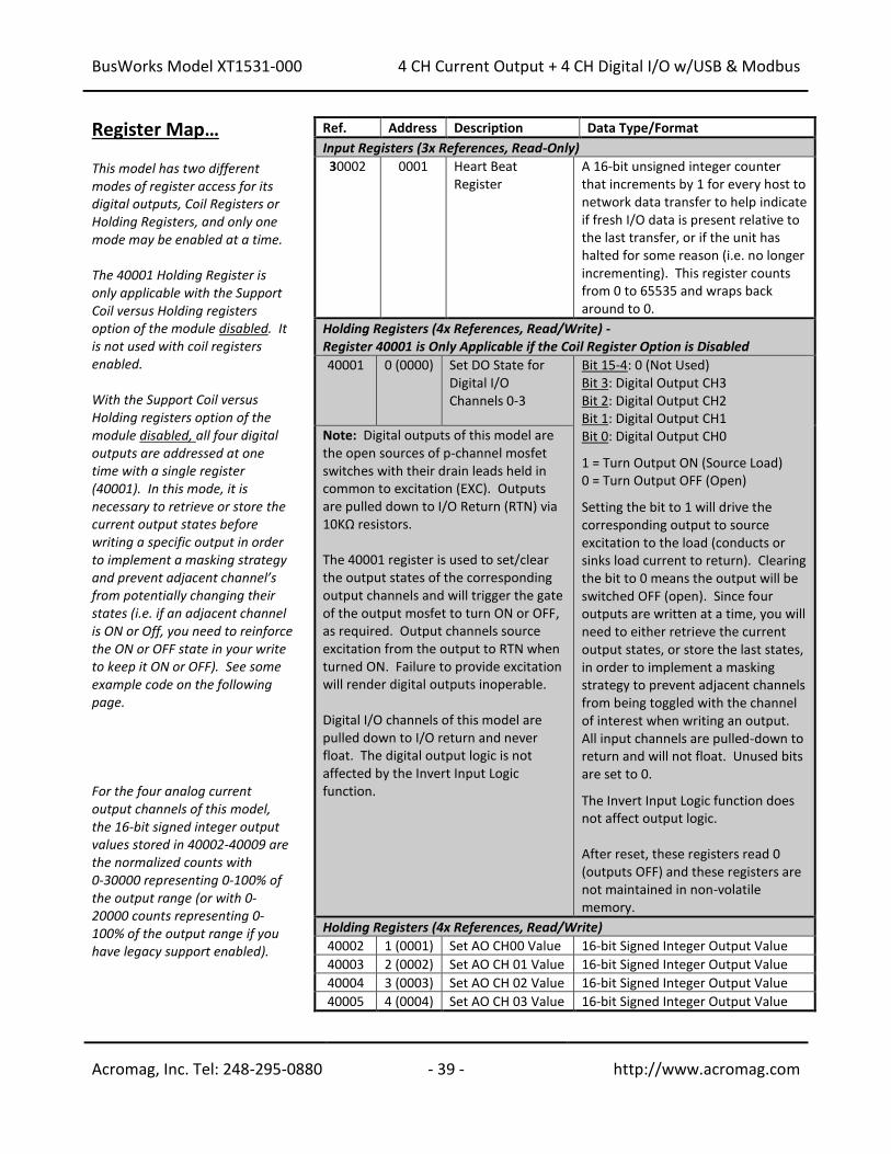
BusWorks Model XT1531-000
4 CH Current Output + 4 CH Digital I/O w/USB & Modbus
Acromag, Inc. Tel: 248-295-0880 - 39 - http://www.acromag.com
- 39 - http://www.acromag.com
Register Map… This model has two different modes of register access for its digital outputs, Coil Registers or Holding Registers, and only one mode may be enabled at a time. The 40001 Holding Register is only applicable with the Support Coil versus Holding registers option of the module disabled. It is not used with coil registers enabled. With the Support Coil versus Holding registers option of the module disabled, all four digital outputs are addressed at one time with a single register (40001). In this mode, it is necessary to retrieve or store the current output states before writing a specific output in order to implement a masking strategy and prevent adjacent channel’s from potentially changing their states (i.e. if an adjacent channel is ON or Off, you need to reinforce the ON or OFF state in your write to keep it ON or OFF). See some example code on the following page. For the four analog current output channels of this model, the 16-bit signed integer output values stored in 40002-40009 are the normalized counts with 0-30000 representing 0-100% of the output range (or with 0-20000 counts representing 0-100% of the output range if you have legacy support enabled).
Ref. Address Description Data Type/Format
Input Registers (3x References, Read-Only)
30002 0001 Heart Beat Register
A 16-bit unsigned integer counter that increments by 1 for every host to network data transfer to help indicate if fresh I/O data is present relative to the last transfer, or if the unit has halted for some reason (i.e. no longer incrementing). This register counts from 0 to 65535 and wraps back around to 0.
Holding Registers (4x References, Read/Write) - Register 40001 is Only Applicable if the Coil Register Option is Disabled
40001 0 (0000) Set DO State for Digital I/O Channels 0-3
Bit 15-4: 0 (Not Used) Bit 3: Digital Output CH3 Bit 2: Digital Output CH2 Bit 1: Digital Output CH1 Bit 0: Digital Output CH0 1 = Turn Output ON (Source Load) 0 = Turn Output OFF (Open) Setting the bit to 1 will drive the corresponding output to source excitation to the load (conducts or sinks load current to return). Clearing the bit to 0 means the output will be switched OFF (open). Since four outputs are written at a time, you will need to either retrieve the current output states, or store the last states, in order to implement a masking strategy to prevent adjacent channels from being toggled with the channel of interest when writing an output. All input channels are pulled-down to return and will not float. Unused bits are set to 0. The Invert Input Logic function does not affect output logic. After reset, these registers read 0 (outputs OFF) and these registers are not maintained in non-volatile memory.
Note: Digital outputs of this model are the open sources of p-channel mosfet switches with their drain leads held in common to excitation (EXC). Outputs are pulled down to I/O Return (RTN) via 10KΩ resistors. The 40001 register is used to set/clear the output states of the corresponding output channels and will trigger the gate of the output mosfet to turn ON or OFF, as required. Output channels source excitation from the output to RTN when turned ON. Failure to provide excitation will render digital outputs inoperable. Digital I/O channels of this model are pulled down to I/O return and never float. The digital output logic is not affected by the Invert Input Logic function.
Holding Registers (4x References, Read/Write)
40002 1 (0001) Set AO CH00 Value 16-bit Signed Integer Output Value
40003 2 (0002) Set AO CH 01 Value 16-bit Signed Integer Output Value
40004 3 (0003) Set AO CH 02 Value 16-bit Signed Integer Output Value
40005 4 (0004) Set AO CH 03 Value 16-bit Signed Integer Output Value
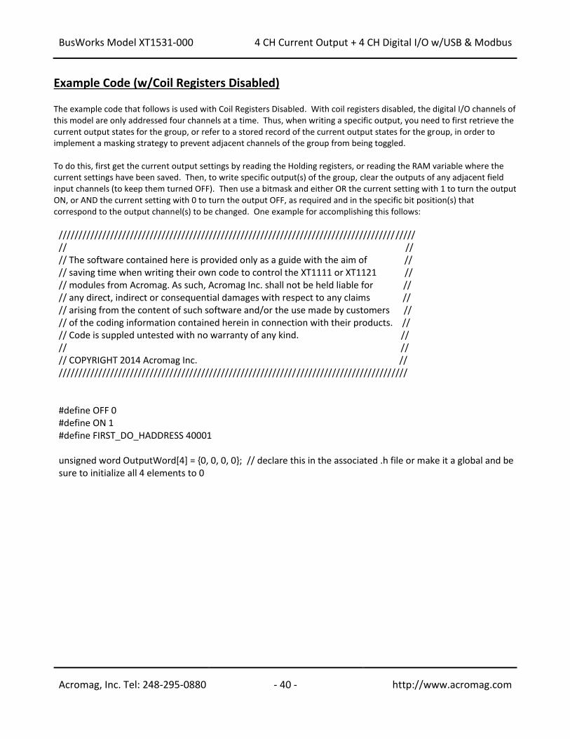
BusWorks Model XT1531-000
4 CH Current Output + 4 CH Digital I/O w/USB & Modbus
Acromag, Inc. Tel: 248-295-0880 - 40 - http://www.acromag.com
- 40 - http://www.acromag.com
Example Code (w/Coil Registers Disabled) The example code that follows is used with Coil Registers Disabled. With coil registers disabled, the digital I/O channels of this model are only addressed four channels at a time. Thus, when writing a specific output, you need to first retrieve the current output states for the group, or refer to a stored record of the current output states for the group, in order to implement a masking strategy to prevent adjacent channels of the group from being toggled. To do this, first get the current output settings by reading the Holding registers, or reading the RAM variable where the current settings have been saved. Then, to write specific output(s) of the group, clear the outputs of any adjacent field input channels (to keep them turned OFF). Then use a bitmask and either OR the current setting with 1 to turn the output ON, or AND the current setting with 0 to turn the output OFF, as required and in the specific bit position(s) that correspond to the output channel(s) to be changed. One example for accomplishing this follows:
////////////////////////////////////////////////////////////////////////////////////////// // // // The software contained here is provided only as a guide with the aim of // // saving time when writing their own code to control the XT1111 or XT1121 // // modules from Acromag. As such, Acromag Inc. shall not be held liable for // // any direct, indirect or consequential damages with respect to any claims // // arising from the content of such software and/or the use made by customers // // of the coding information contained herein in connection with their products. // // Code is suppled untested with no warranty of any kind. // // // // COPYRIGHT 2014 Acromag Inc. // //////////////////////////////////////////////////////////////////////////////////////// #define OFF 0 #define ON 1 #define FIRST_DO_HADDRESS 40001 unsigned word OutputWord[4] = 0, 0, 0, 0; // declare this in the associated .h file or make it a global and be sure to initialize all 4 elements to 0
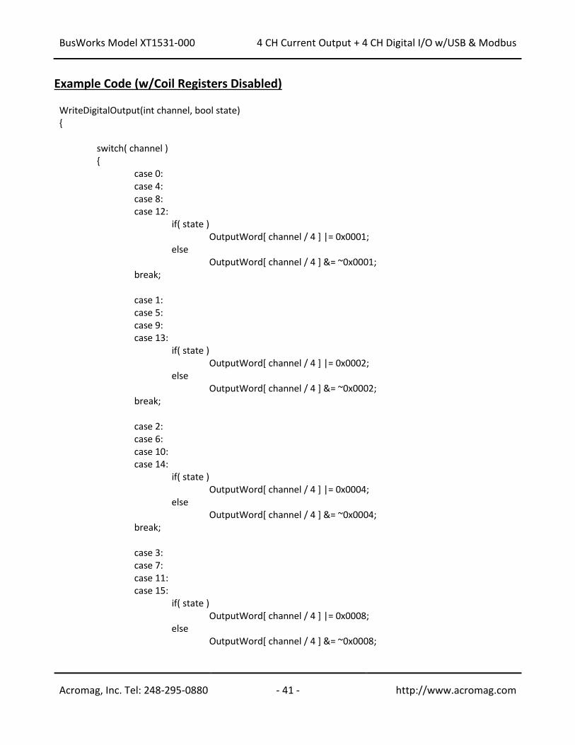
BusWorks Model XT1531-000
4 CH Current Output + 4 CH Digital I/O w/USB & Modbus
Acromag, Inc. Tel: 248-295-0880 - 41 - http://www.acromag.com
- 41 - http://www.acromag.com
Example Code (w/Coil Registers Disabled) WriteDigitalOutput(int channel, bool state) switch( channel ) case 0: case 4: case 8: case 12: if( state ) OutputWord[ channel / 4 ] |= 0x0001; else OutputWord[ channel / 4 ] &= ~0x0001; break; case 1: case 5: case 9: case 13: if( state ) OutputWord[ channel / 4 ] |= 0x0002; else OutputWord[ channel / 4 ] &= ~0x0002; break; case 2: case 6: case 10: case 14: if( state ) OutputWord[ channel / 4 ] |= 0x0004; else OutputWord[ channel / 4 ] &= ~0x0004; break; case 3: case 7: case 11: case 15: if( state ) OutputWord[ channel / 4 ] |= 0x0008; else OutputWord[ channel / 4 ] &= ~0x0008;
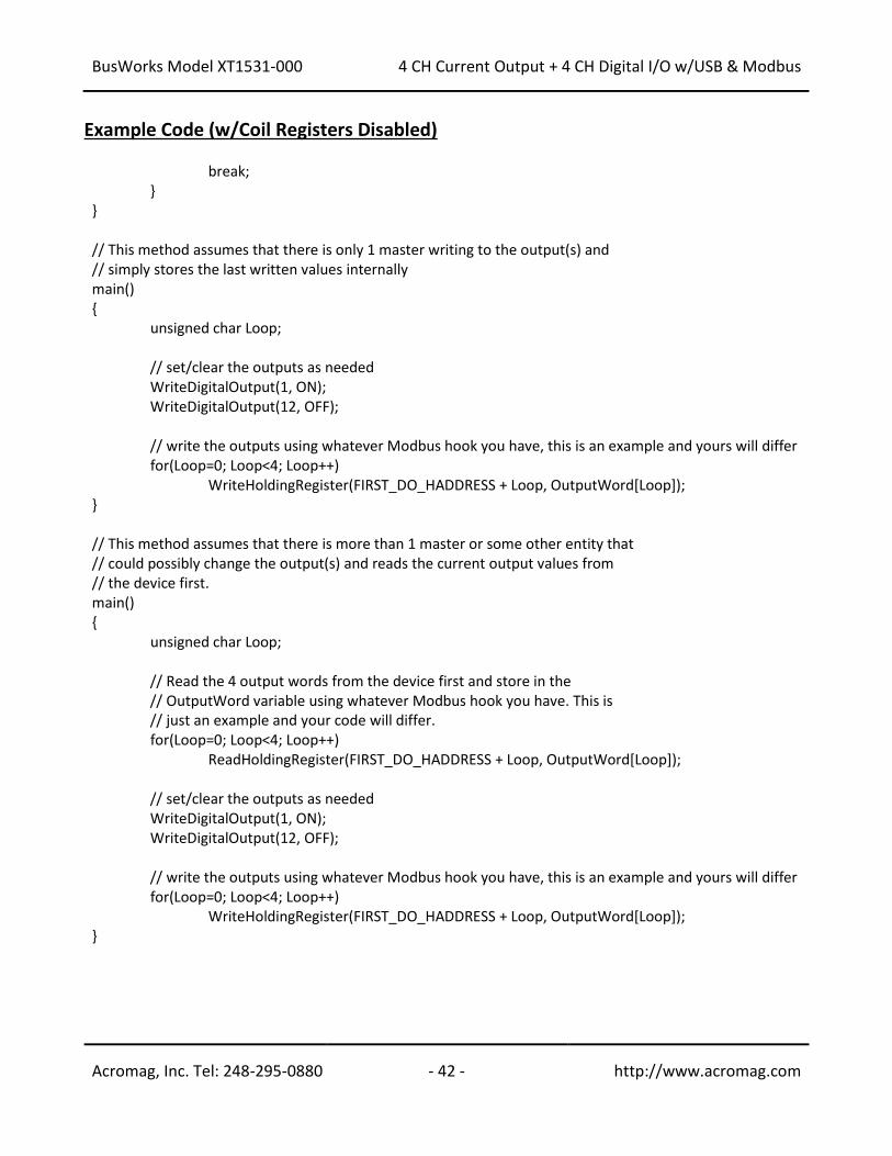
BusWorks Model XT1531-000
4 CH Current Output + 4 CH Digital I/O w/USB & Modbus
Acromag, Inc. Tel: 248-295-0880 - 42 - http://www.acromag.com
- 42 - http://www.acromag.com
Example Code (w/Coil Registers Disabled) break; // This method assumes that there is only 1 master writing to the output(s) and // simply stores the last written values internally main() unsigned char Loop; // set/clear the outputs as needed WriteDigitalOutput(1, ON); WriteDigitalOutput(12, OFF); // write the outputs using whatever Modbus hook you have, this is an example and yours will differ for(Loop=0; Loop<4; Loop++) WriteHoldingRegister(FIRST_DO_HADDRESS + Loop, OutputWord[Loop]); // This method assumes that there is more than 1 master or some other entity that // could possibly change the output(s) and reads the current output values from // the device first. main() unsigned char Loop; // Read the 4 output words from the device first and store in the // OutputWord variable using whatever Modbus hook you have. This is // just an example and your code will differ. for(Loop=0; Loop<4; Loop++) ReadHoldingRegister(FIRST_DO_HADDRESS + Loop, OutputWord[Loop]); // set/clear the outputs as needed WriteDigitalOutput(1, ON); WriteDigitalOutput(12, OFF); // write the outputs using whatever Modbus hook you have, this is an example and yours will differ for(Loop=0; Loop<4; Loop++) WriteHoldingRegister(FIRST_DO_HADDRESS + Loop, OutputWord[Loop]);
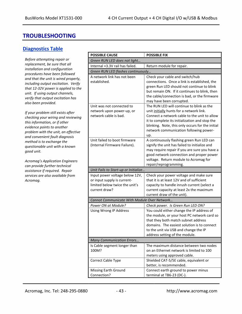
BusWorks Model XT1531-000
4 CH Current Output + 4 CH Digital I/O w/USB & Modbus
Acromag, Inc. Tel: 248-295-0880 - 43 - http://www.acromag.com
- 43 - http://www.acromag.com
TROUBLESHOOTING
Diagnostics Table Before attempting repair or replacement, be sure that all installation and configuration procedures have been followed and that the unit is wired properly, including output excitation. Verify that 12-32V power is applied to the unit. If using output channels, verify that output excitation has also been provided. If your problem still exists after checking your wiring and reviewing this information, or if other evidence points to another problem with the unit, an effective and convenient fault diagnosis method is to exchange the questionable unit with a known good unit. Acromag’s Application Engineers can provide further technical assistance if required. Repair services are also available from Acromag.
POSSIBLE CAUSE POSSIBLE FIX
Green RUN LED does not light…
Internal +3.3V rail has failed. Return module for repair.
Green RUN LED flashes continuously…
A network link has not been established.
Check your cable and switch/hub connections. Once a link is established, the green Run LED should not continue to blink but remain ON. If it continues to blink, then the cable/connection is bad, or the firmware may have been corrupted.
Unit was not connected to network upon power-up, or network cable is bad.
The RUN LED will continue to blink as the unit initially hunts for a network link. Connect a network cable to the unit to allow it to complete its initialization and stop the blinking. Note, this only occurs for the initial network communication following power-up.
Unit failed to boot firmware (Internal Firmware Failure).
A continuously flashing green Run LED can signify the unit has failed to initialize and may require repair if you are sure you have a good network connection and proper power voltage. Return module to Acromag for repair/reprogramming.
Unit Fails to Start-up or Initialize…
Input power voltage below 12V, or input supply is current-limited below twice the unit’s current draw?
Check your power voltage and make sure that it is at least 12V and of sufficient capacity to handle inrush current (select a current capacity at least 2x the maximum current draw of the unit).
Cannot Communicate With Module Over Network…
Power ON at Module? Check power. Is Green Run LED ON?
Using Wrong IP Address You could either change the IP address of the module, or your host PC network card so that they both match subnet address domains. The easiest solution is to connect to the unit via USB and change the IP address setting of the module.
Many Communication Errors…
Is Cable segment longer than 100M?
The maximum distance between two nodes on an Ethernet network is limited to 100 meters using approved cable.
Correct Cable Type Shielded CAT-5/5E cable, equivalent or better, is recommended.
Missing Earth Ground Connection?
Connect earth ground to power minus terminal at TB6-23 (DC-).
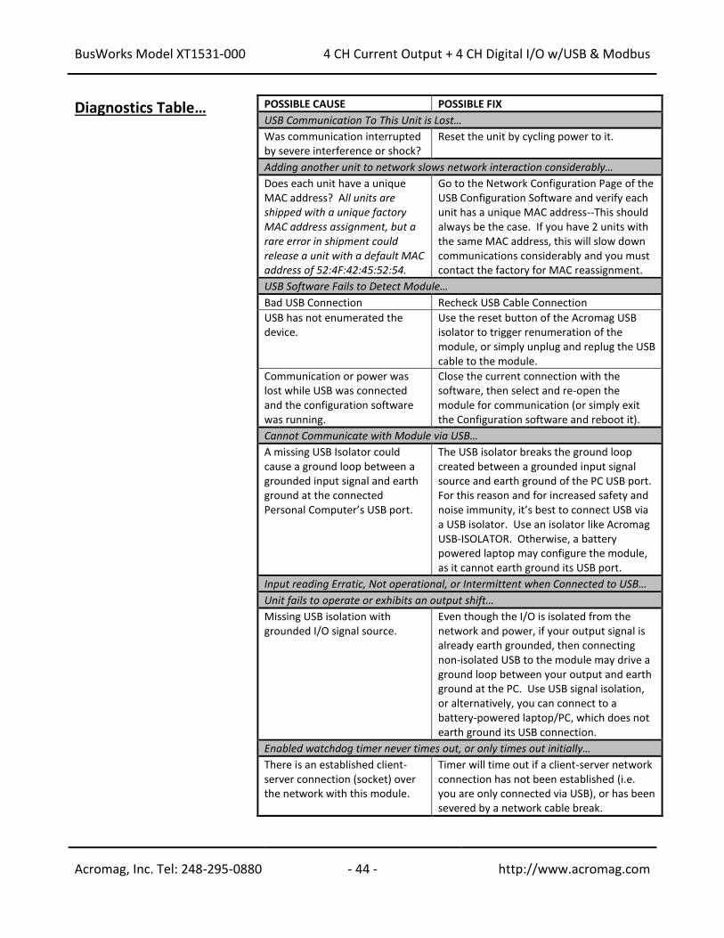
BusWorks Model XT1531-000
4 CH Current Output + 4 CH Digital I/O w/USB & Modbus
Acromag, Inc. Tel: 248-295-0880 - 44 - http://www.acromag.com
- 44 - http://www.acromag.com
Diagnostics Table… POSSIBLE CAUSE POSSIBLE FIX
USB Communication To This Unit is Lost…
Was communication interrupted by severe interference or shock?
Reset the unit by cycling power to it.
Adding another unit to network slows network interaction considerably…
Does each unit have a unique MAC address? All units are shipped with a unique factory MAC address assignment, but a rare error in shipment could release a unit with a default MAC address of 52:4F:42:45:52:54.
Go to the Network Configuration Page of the USB Configuration Software and verify each unit has a unique MAC address--This should always be the case. If you have 2 units with the same MAC address, this will slow down communications considerably and you must contact the factory for MAC reassignment.
USB Software Fails to Detect Module…
Bad USB Connection Recheck USB Cable Connection
USB has not enumerated the device.
Use the reset button of the Acromag USB isolator to trigger renumeration of the module, or simply unplug and replug the USB cable to the module.
Communication or power was lost while USB was connected and the configuration software was running.
Close the current connection with the software, then select and re-open the module for communication (or simply exit the Configuration software and reboot it).
Cannot Communicate with Module via USB…
A missing USB Isolator could cause a ground loop between a grounded input signal and earth ground at the connected Personal Computer’s USB port.
The USB isolator breaks the ground loop created between a grounded input signal source and earth ground of the PC USB port. For this reason and for increased safety and noise immunity, it’s best to connect USB via a USB isolator. Use an isolator like Acromag USB-ISOLATOR. Otherwise, a battery powered laptop may configure the module, as it cannot earth ground its USB port.
Input reading Erratic, Not operational, or Intermittent when Connected to USB…
Unit fails to operate or exhibits an output shift…
Missing USB isolation with grounded I/O signal source.
Even though the I/O is isolated from the network and power, if your output signal is already earth grounded, then connecting non-isolated USB to the module may drive a ground loop between your output and earth ground at the PC. Use USB signal isolation, or alternatively, you can connect to a battery-powered laptop/PC, which does not earth ground its USB connection.
Enabled watchdog timer never times out, or only times out initially…
There is an established client-server connection (socket) over the network with this module.
Timer will time out if a client-server network connection has not been established (i.e. you are only connected via USB), or has been severed by a network cable break.
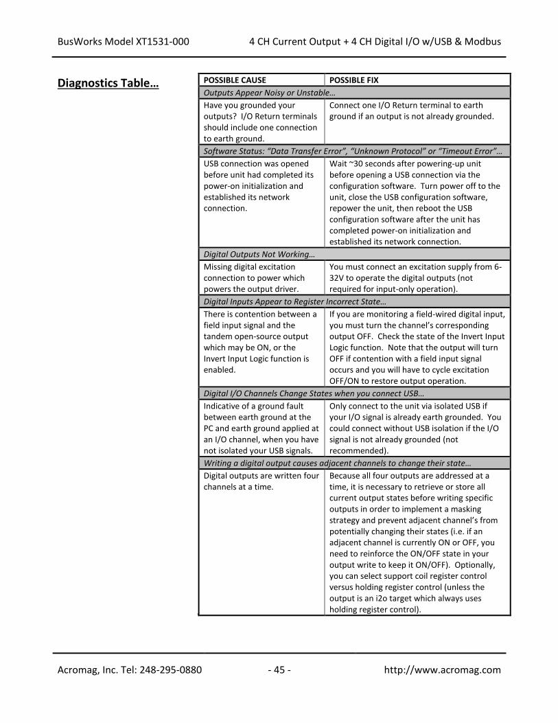
BusWorks Model XT1531-000
4 CH Current Output + 4 CH Digital I/O w/USB & Modbus
Acromag, Inc. Tel: 248-295-0880 - 45 - http://www.acromag.com
- 45 - http://www.acromag.com
Diagnostics Table… POSSIBLE CAUSE POSSIBLE FIX
Outputs Appear Noisy or Unstable…
Have you grounded your outputs? I/O Return terminals should include one connection to earth ground.
Connect one I/O Return terminal to earth ground if an output is not already grounded.
Software Status: “Data Transfer Error”, “Unknown Protocol” or “Timeout Error”…
USB connection was opened before unit had completed its power-on initialization and established its network connection.
Wait ~30 seconds after powering-up unit before opening a USB connection via the configuration software. Turn power off to the unit, close the USB configuration software, repower the unit, then reboot the USB configuration software after the unit has completed power-on initialization and established its network connection.
Digital Outputs Not Working…
Missing digital excitation connection to power which powers the output driver.
You must connect an excitation supply from 6-32V to operate the digital outputs (not required for input-only operation).
Digital Inputs Appear to Register Incorrect State…
There is contention between a field input signal and the tandem open-source output which may be ON, or the Invert Input Logic function is enabled.
If you are monitoring a field-wired digital input, you must turn the channel’s corresponding output OFF. Check the state of the Invert Input Logic function. Note that the output will turn OFF if contention with a field input signal occurs and you will have to cycle excitation OFF/ON to restore output operation.
Digital I/O Channels Change States when you connect USB…
Indicative of a ground fault between earth ground at the PC and earth ground applied at an I/O channel, when you have not isolated your USB signals.
Only connect to the unit via isolated USB if your I/O signal is already earth grounded. You could connect without USB isolation if the I/O signal is not already grounded (not recommended).
Writing a digital output causes adjacent channels to change their state…
Digital outputs are written four channels at a time.
Because all four outputs are addressed at a time, it is necessary to retrieve or store all current output states before writing specific outputs in order to implement a masking strategy and prevent adjacent channel’s from potentially changing their states (i.e. if an adjacent channel is currently ON or OFF, you need to reinforce the ON/OFF state in your output write to keep it ON/OFF). Optionally, you can select support coil register control versus holding register control (unless the output is an i2o target which always uses holding register control).
`
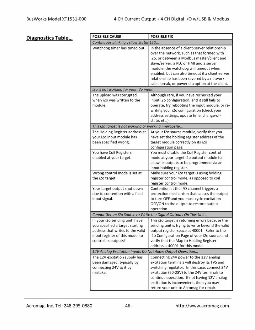
BusWorks Model XT1531-000
4 CH Current Output + 4 CH Digital I/O w/USB & Modbus
Acromag, Inc. Tel: 248-295-0880 - 46 - http://www.acromag.com
- 46 - http://www.acromag.com
Diagnostics Table… POSSIBLE CAUSE POSSIBLE FIX
Continuous blinking yellow status LED…
Watchdog timer has timed out. In the absence of a client-server relationship over the network, such as that formed with i2o, or between a Modbus master/client and slave/server, a PLC or HMI and a server module, the watchdog will timeout when enabled, but can also timeout if a client-server relationship has been severed by a network cable break, or power disruption at the client.
i2o is not working for your i2o input…
The upload was corrupted when i2o was written to the module.
Although rare, if you have rechecked your input i2o configuration, and it still fails to operate, try rebooting the input module, or re-writing your i2o configuration (check your address settings, update time, change-of-state, etc.).
This i2o target is not working or working improperly…
The Holding Register address at your i2o input module has been specified wrong.
At your i2o source module, verify that you have set the holding register address of the target module correctly on its i2o configuration page.
You have Coil Registers enabled at your target.
You must disable the Coil Register control mode at your target i2o output module to allow its outputs to be programmed via an input holding register.
Wrong control mode is set at the i2o target.
Make sure your i2o target is using holding register control mode, as opposed to coil register control mode.
Your target output shut down due to contention with a field input signal.
Contention at the I/O channel triggers a protection mechanism that causes the output to turn OFF and you must cycle excitation OFF/ON to the output to restore output operation.
Cannot Get an i2o Source to Write the Digital Outputs On This Unit…
In your i2o sending unit, have you specified a target starting address that writes to the valid input register of this model to control its outputs?
This i2o target is returning errors because the sending unit is trying to write beyond the valid output register space at 40001. Refer to the i2o Configuration Page of your i2o source and verify that the Map to Holding Register address is 40001 for this model.
12V Analog Excitation Inputs Do Not Allow Output Operation…
The 12V excitation supply has been damaged, typically by connecting 24V to it by mistake.
Connecting 24V power to the 12V analog excitation terminals will destroy its TVS and switching regulator. In this case, connect 24V excitation (20-28V) to the 24V terminals to continue operation. If not having 12V analog excitation is inconvenient, then you may return your unit to Acromag for repair.
`
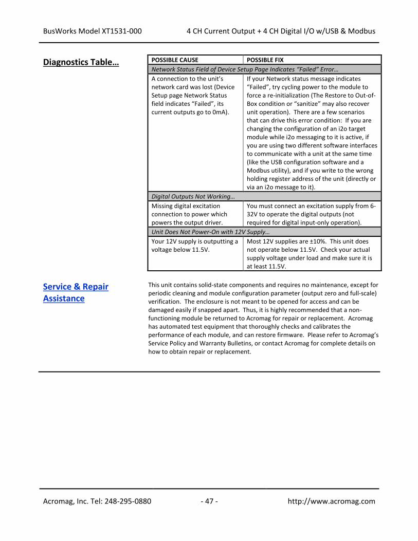
BusWorks Model XT1531-000
4 CH Current Output + 4 CH Digital I/O w/USB & Modbus
Acromag, Inc. Tel: 248-295-0880 - 47 - http://www.acromag.com
- 47 - http://www.acromag.com
Diagnostics Table… POSSIBLE CAUSE POSSIBLE FIX
Network Status Field of Device Setup Page Indicates “Failed” Error…
A connection to the unit’s network card was lost (Device Setup page Network Status field indicates “Failed”, its current outputs go to 0mA).
If your Network status message indicates “Failed”, try cycling power to the module to force a re-initialization (The Restore to Out-of-Box condition or “sanitize” may also recover unit operation). There are a few scenarios that can drive this error condition: If you are changing the configuration of an i2o target module while i2o messaging to it is active, if you are using two different software interfaces to communicate with a unit at the same time (like the USB configuration software and a Modbus utility), and if you write to the wrong holding register address of the unit (directly or via an i2o message to it).
Digital Outputs Not Working…
Missing digital excitation connection to power which powers the output driver.
You must connect an excitation supply from 6-32V to operate the digital outputs (not required for digital input-only operation).
Unit Does Not Power-On with 12V Supply…
Your 12V supply is outputting a voltage below 11.5V.
Most 12V supplies are ±10%. This unit does not operate below 11.5V. Check your actual supply voltage under load and make sure it is at least 11.5V.
Service & Repair Assistance
This unit contains solid-state components and requires no maintenance, except for periodic cleaning and module configuration parameter (output zero and full-scale) verification. The enclosure is not meant to be opened for access and can be damaged easily if snapped apart. Thus, it is highly recommended that a non-functioning module be returned to Acromag for repair or replacement. Acromag has automated test equipment that thoroughly checks and calibrates the performance of each module, and can restore firmware. Please refer to Acromag’s Service Policy and Warranty Bulletins, or contact Acromag for complete details on how to obtain repair or replacement.
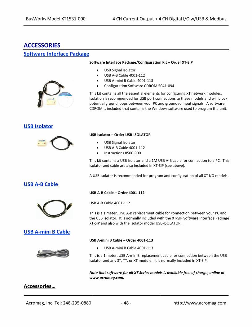
BusWorks Model XT1531-000
4 CH Current Output + 4 CH Digital I/O w/USB & Modbus
Acromag, Inc. Tel: 248-295-0880 - 48 - http://www.acromag.com
- 48 - http://www.acromag.com
ACCESSORIES
Software Interface Package
Software Interface Package/Configuration Kit – Order XT-SIP
• USB Signal Isolator
• USB A-B Cable 4001-112
• USB A-mini B Cable 4001-113
• Configuration Software CDROM 5041-094 This kit contains all the essential elements for configuring XT network modules. Isolation is recommended for USB port connections to these models and will block potential ground loops between your PC and grounded input signals. A software CDROM is included that contains the Windows software used to program the unit.
USB Isolator
USB Isolator – Order USB-ISOLATOR
• USB Signal Isolator
• USB A-B Cable 4001-112
• Instructions 8500-900 This kit contains a USB isolator and a 1M USB A-B cable for connection to a PC. This isolator and cable are also included in XT-SIP (see above). A USB isolator is recommended for program and configuration of all XT I/O models.
USB A-B Cable
USB A-B Cable – Order 4001-112
• USB A-B Cable 4001-112 This is a 1 meter, USB A-B replacement cable for connection between your PC and the USB isolator. It is normally included with the XT-SIP Software Interface Package XT-SIP and also with the isolator model USB-ISOLATOR.
USB A-mini B Cable
USB A-mini B Cable – Order 4001-113
• USB A-mini B Cable 4001-113 This is a 1 meter, USB A-miniB replacement cable for connection between the USB isolator and any ST, TT, or XT module. It is normally included in XT-SIP.
Note that software for all XT Series models is available free of charge, online at www.acromag.com.
Accessories…
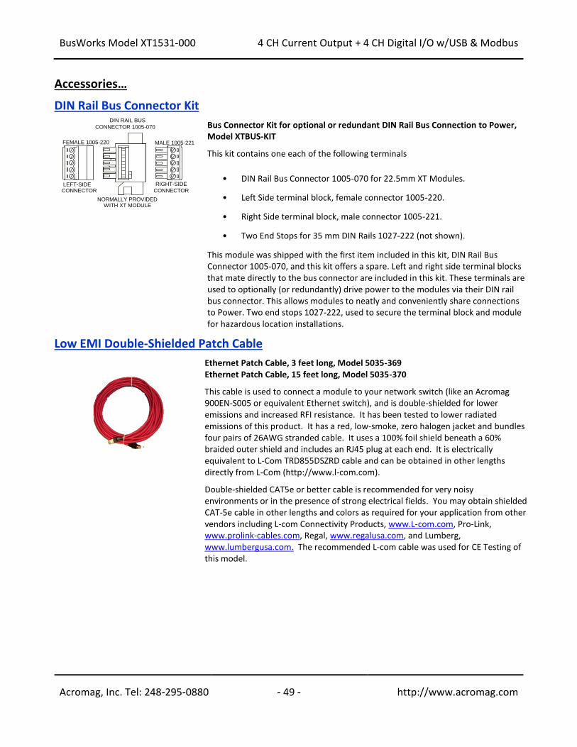
BusWorks Model XT1531-000
4 CH Current Output + 4 CH Digital I/O w/USB & Modbus
Acromag, Inc. Tel: 248-295-0880 - 49 - http://www.acromag.com
- 49 - http://www.acromag.com
Accessories…
DIN Rail Bus Connector Kit
Bus Connector Kit for optional or redundant DIN Rail Bus Connection to Power, Model XTBUS-KIT This kit contains one each of the following terminals
• DIN Rail Bus Connector 1005-070 for 22.5mm XT Modules.
• Left Side terminal block, female connector 1005-220.
• Right Side terminal block, male connector 1005-221.
• Two End Stops for 35 mm DIN Rails 1027-222 (not shown).
This module was shipped with the first item included in this kit, DIN Rail Bus Connector 1005-070, and this kit offers a spare. Left and right side terminal blocks that mate directly to the bus connector are included in this kit. These terminals are used to optionally (or redundantly) drive power to the modules via their DIN rail bus connector. This allows modules to neatly and conveniently share connections to Power. Two end stops 1027-222, used to secure the terminal block and module for hazardous location installations.
Low EMI Double-Shielded Patch Cable
Ethernet Patch Cable, 3 feet long, Model 5035-369 Ethernet Patch Cable, 15 feet long, Model 5035-370 This cable is used to connect a module to your network switch (like an Acromag 900EN-S005 or equivalent Ethernet switch), and is double-shielded for lower emissions and increased RFI resistance. It has been tested to lower radiated emissions of this product. It has a red, low-smoke, zero halogen jacket and bundles four pairs of 26AWG stranded cable. It uses a 100% foil shield beneath a 60% braided outer shield and includes an RJ45 plug at each end. It is electrically equivalent to L-Com TRD855DSZRD cable and can be obtained in other lengths directly from L-Com (http://www.l-com.com). Double-shielded CAT5e or better cable is recommended for very noisy environments or in the presence of strong electrical fields. You may obtain shielded CAT-5e cable in other lengths and colors as required for your application from other vendors including L-com Connectivity Products, www.L-com.com, Pro-Link, www.prolink-cables.com, Regal, www.regalusa.com, and Lumberg, www.lumbergusa.com. The recommended L-com cable was used for CE Testing of this model.
FEMALE 1005-220
LEFT-SIDE
NORMALLY PROVIDEDWITH XT MODULE
MALE 1005-221
RIGHT-SIDE
DIN RAIL BUS
CONNECTOR 1005-070
CONNECTORCONNECTOR
BusWorks Model XT1531-000
4 CH Current Output + 4 CH Digital I/O w/USB & Modbus
Acromag, Inc. Tel: 248-295-0880 - 50 - http://www.acromag.com
- 50 - http://www.acromag.com
SPECIFICATIONS
Model Number XT1531-000 (Four Current Output Channels combined w/ Four Sourcing Digital I/O Channels) 4 AO & 4 DIO Output Channels (Combination Current Output Module with Sourcing Digital I/O) Modbus TCP/IP Support DC Powered CE Approved Includes UL/cUL Class I, Division 2 approvals
The XT1531-000 is a member of the Acromag DIN-Rail mounted, “Busworks” family of network I/O modules in the XT Series. The XT1531-000 model provides four channels of DC current output, plus four sourcing digital I/O channels. This model operates over Ethernet using Modbus TCP/IP, but is setup and calibrated for network operation using USB. The trailing “-000” model suffix denotes DC power with CE & UL/cUL Class I, Division 2 Approvals. Models are mounted on standard “T” Type DIN rail and include plug-in terminals. Power can be optionally (or redundantly) bussed along the DIN rail (see Power Connections). Outputs of this model require separate connections to power in order to operate them. Reconfiguration of any XT model will require use of the XT-SIP configuration kit, ordered separately (see Accessories section).
Analog Outputs Excitation for the analog outputs is required at TB3 to operate them. WARNING: If you make the mistake of connecting 24V excitation to the 12V excitation terminals, you will damage the 12V TVS and switching regulator. Be very careful when making excitation connections to make it to the correct terminals. If 12V input is damaged, you can connect 24V to the 24V excitation terminals to continue operation.
Four separate DC current outputs share return and include transient voltage suppression. You must connect 12V or 24V excitation to operate the outputs (connect analog excitation at TB3). Positive current is pulled from the analog excitation supply, sourced from the output channel, and pushed through the load to Return (RTN). The unit must be wired and configured for the intended output (see Connections section for details). The following paragraphs summarize this model’s analog output type, ranges, and applicable specifications: Output Ranges: Select 0-20mA DC or 4-20mA DC (a sub-range of 0-20mA range). Output Accuracy: Factory calibrated to better than ±0.1%. Manual calibration of current outputs can be done to improve output accuracy to better than 0.05%. Output Load Resistance Range: 250-550Ω. Maximum output resistance is a function of the 14.8V internal voltage rail Vexc, the maximum output current Io_max, and the required internal overhead of 2.4V via the relationship Rload_max ~ (14.8 – 2.4)/Io_max. A minimum load of 225Ω is imposed to limit power dissipation to safe levels at elevated temperature. Analog Output Excitation (TB3): There are two separate excitation inputs located at TB3: one for 12V power sources (10-15V) and one for 24V power (20-28V). Both excitation sources are diode-coupled to the current output excitation rail, allowing analog excitation to be supplied redundantly if required. See Warning at left. Output Overvoltage Protection: Bipolar Transient Voltage Suppressers (TVS) with a clamp level above 14V typical. Output Maximum Current: To simplify programming, the output DAC is normalized to 0-30000 for 0-100% of output (or optionally to 0-20000 w/ Legacy support). This 16-bit count is digitally limited to 32768 (~109.2%). This equates to 21.845mA for the 0-20mA range, and 21.476mA for the 4-20mA range. Output Compliance: 12.4V typical (with a 14.8V internal excitation rail). The output can thus drive its 21.845mA maximum current into ~567Ω typical. See the Power Requirements – Excitation specification. Output Update Rate: When written & continuously refreshed every 5 seconds. Output Cable Length: Output interface cables should not exceed 30m in length for rated performance.
Output Temperature Drift: Better than 60ppm/C (±0.0060%/C).
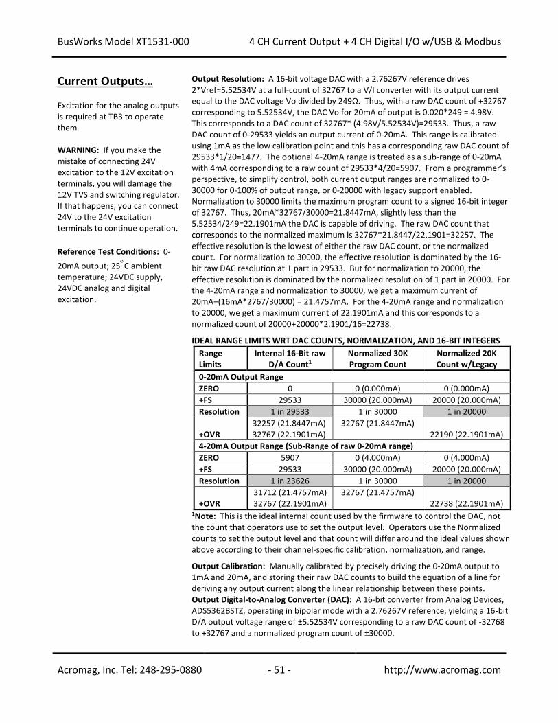
BusWorks Model XT1531-000
4 CH Current Output + 4 CH Digital I/O w/USB & Modbus
Acromag, Inc. Tel: 248-295-0880 - 51 - http://www.acromag.com
- 51 - http://www.acromag.com
Current Outputs… Excitation for the analog outputs is required at TB3 to operate them. WARNING: If you make the mistake of connecting 24V excitation to the 12V excitation terminals, you will damage the 12V TVS and switching regulator. If that happens, you can connect 24V to the 24V excitation terminals to continue operation.
Reference Test Conditions: 0-
20mA output; 25C ambient temperature; 24VDC supply, 24VDC analog and digital excitation.
Output Resolution: A 16-bit voltage DAC with a 2.76267V reference drives 2*Vref=5.52534V at a full-count of 32767 to a V/I converter with its output current equal to the DAC voltage Vo divided by 249Ω. Thus, with a raw DAC count of +32767 corresponding to 5.52534V, the DAC Vo for 20mA of output is 0.020*249 = 4.98V. This corresponds to a DAC count of 32767* (4.98V/5.52534V)=29533. Thus, a raw DAC count of 0-29533 yields an output current of 0-20mA. This range is calibrated using 1mA as the low calibration point and this has a corresponding raw DAC count of 29533*1/20=1477. The optional 4-20mA range is treated as a sub-range of 0-20mA with 4mA corresponding to a raw count of 29533*4/20=5907. From a programmer’s perspective, to simplify control, both current output ranges are normalized to 0-30000 for 0-100% of output range, or 0-20000 with legacy support enabled. Normalization to 30000 limits the maximum program count to a signed 16-bit integer of 32767. Thus, 20mA*32767/30000=21.8447mA, slightly less than the 5.52534/249=22.1901mA the DAC is capable of driving. The raw DAC count that corresponds to the normalized maximum is 32767*21.8447/22.1901=32257. The effective resolution is the lowest of either the raw DAC count, or the normalized count. For normalization to 30000, the effective resolution is dominated by the 16-bit raw DAC resolution at 1 part in 29533. But for normalization to 20000, the effective resolution is dominated by the normalized resolution of 1 part in 20000. For the 4-20mA range and normalization to 30000, we get a maximum current of 20mA+(16mA*2767/30000) = 21.4757mA. For the 4-20mA range and normalization to 20000, we get a maximum current of 22.1901mA and this corresponds to a normalized count of 20000+20000*2.1901/16=22738. IDEAL RANGE LIMITS WRT DAC COUNTS, NORMALIZATION, AND 16-BIT INTEGERS
Range Limits
Internal 16-Bit raw D/A Count1
Normalized 30K Program Count
Normalized 20K Count w/Legacy
0-20mA Output Range
ZERO 0 0 (0.000mA) 0 (0.000mA)
+FS 29533 30000 (20.000mA) 20000 (20.000mA)
Resolution 1 in 29533 1 in 30000 1 in 20000
+OVR
32257 (21.8447mA) 32767 (22.1901mA)
32767 (21.8447mA) 22190 (22.1901mA)
4-20mA Output Range (Sub-Range of raw 0-20mA range)
ZERO 5907 0 (4.000mA) 0 (4.000mA)
+FS 29533 30000 (20.000mA) 20000 (20.000mA)
Resolution 1 in 23626 1 in 30000 1 in 20000
+OVR
31712 (21.4757mA) 32767 (22.1901mA)
32767 (21.4757mA) 22738 (22.1901mA)
1Note: This is the ideal internal count used by the firmware to control the DAC, not the count that operators use to set the output level. Operators use the Normalized counts to set the output level and that count will differ around the ideal values shown above according to their channel-specific calibration, normalization, and range. Output Calibration: Manually calibrated by precisely driving the 0-20mA output to 1mA and 20mA, and storing their raw DAC counts to build the equation of a line for deriving any output current along the linear relationship between these points. Output Digital-to-Analog Converter (DAC): A 16-bit converter from Analog Devices, ADS5362BSTZ, operating in bipolar mode with a 2.76267V reference, yielding a 16-bit D/A output voltage range of ±5.52534V corresponding to a raw DAC count of -32768 to +32767 and a normalized program count of ±30000.
BusWorks Model XT1531-000
4 CH Current Output + 4 CH Digital I/O w/USB & Modbus
Acromag, Inc. Tel: 248-295-0880 - 52 - http://www.acromag.com
- 52 - http://www.acromag.com
Digital Outputs This model has four tandem digital input and output channels.
Excitation for the sourcing digital outputs is required at TB6 to operate them. To control higher voltages and/or currents, or for controlling AC, an interposing relay may be used (see Note).
This model has four open-source, smart, p-channel mosfet switches with a common drain connection to the digital excitation source at TB6-22. It provides high-side switching between the digital excitation and the load connected between the output channel at TB4 and return at TB5. It is intended for DC voltage sourcing applications only. The outputs will drive any rated load up to 250mA with one side connected return. Outputs have tandem inputs which provide true loopback monitoring of the output state, or the inputs can be used to monitor field inputs with the output OFF. Individual I/O channels are pulled down to I/O Return (connected at RTN terminal) with 10KΩ resistors and do not float. External excitation is required for digital output operation and this is connected between the EXC and RTN terminals of TB6 (terminal numbers 22 and 21 respectively). Digital Output “OFF” Voltage Range: 0 to 32V DC. Limit voltage to less than 36V peak, or damage to the unit may result. Use protection when switching inductive loads (for example, use a reverse shunt diode at the inductive load). Output Active Current Limitation: The unit limits load current to a shorted load to 0.6A typical, 0.4A-0.9A range (EXC=13V and 0.01Ω load resistance). This limit works with a latched thermal shutdown to help protect the output channel from damage due to overload (cycle excitation OFF/ON to restore output operation after a shutdown). Output Thermal Shutdown: Individual outputs will shutdown and latch off for thermal overload conditions that drive the junction temperature into the region from 150° to 200°C. If your outputs stop working, the I/O pin is pulled low and the output must be cycled OFF/ON to restore operation. Output Under-voltage Shutdown: Outputs will shut-down if their excitation voltage is less than 6.0V (3V-6V threshold). Output Overvoltage Shutdown: Outputs will shut-down if their excitation voltage exceeds 36V minimum. Output Ground Loss Protection: The output automatically turns off if the ground lead is disconnected (RTN). Output “OFF” Leakage Current: 50uA maximum per channel (mosfet only). Does not include the input bias current for the tandem digital input (see Note below).
Note: The 100K series input buffer resistors in combination with the +3.3V voltage diode clamps at the input buffer will tend to increase the off-state current with increasing output voltage (up to 3.5mA at 32V). This is a consequence of the input buffer circuitry being connected in tandem to the output mosfet source lead at every I/O channel, and the presence of a 10KΩ pull-down on the input. Output “ON” Current Range: 0 to 250mA DC, continuous (up to 1A total for all 4 channels combined). No deration is required at elevated ambient. Match one TB5 return (RTN) to each of 4 output loads.
Output Rds ON Resistance: 0.5 typical at 0.25A and 25°C, 1.0 Maximum. Output Response Time: 10ms typical. Does not include network time. The actual output switch time will vary with network traffic, interrupts, and output load. Note: Per UL, when the outputs are used to control interposing relays for switching AC and DC devices of higher voltage/current, the coil ratings for the interposing relay shall not exceed 24VDC, 100mA.
BusWorks Model XT1531-000
4 CH Current Output + 4 CH Digital I/O w/USB & Modbus
Acromag, Inc. Tel: 248-295-0880 - 53 - http://www.acromag.com
- 53 - http://www.acromag.com
Digital Outputs… Note: You must connect digital excitation to operate digital outputs. Input only operation does not require Excitation.
Digital Output Excitation (Required for Operation): Excitation must be from 6-32V and 14mA minimum (at 32V and no load), and is applied between the digital I/O EXC and Return (at TB6). The digital excitation current capacity should be at least 1.2A to deliver full rated load to all four outputs. Reverse voltage protection is included. The actual capacity of your excitation supply will depend on the loads and number of channels being loaded. The high-side switched outputs will source the excitation voltage to the load when turned ON, but are also powered from it, and outputs cannot operate without this excitation. The EXC terminal is tied in common to the drains of each output channel switch. The source leads of each switch are pulled down to return via 10KΩ pull-down resistors and drive the output load. You do not need excitation to operate the tandem digital inputs of this model, only the outputs. Digital I/O Pull-Downs: Individual digital I/O channels have 10KΩ pull-downs to return and will never float. The installed resistor is one element of a four element isolated SIP resistor (8 pins) and rated to 0.3W per element up to 70°C (refer to Bourns 4308M-102-103LF parts). If your application requires a stronger pull-down (lower resistance), you will have to wire it externally in parallel with your load, being careful that you do not exceed 250mA of source current per output (load max plus pull-down current). IMPORTANT: If you trigger the output’s protection mechanism, perhaps via accidental contention between an output channel and a field input signal, it shuts OFF and you must cycle output excitation OFF/ON to restore output operation.
Digital Inputs This model has four tandem digital input and output channels. No additional excitation is required to operate the digital inputs, as excitation is only required for output operation. Always turn digital outputs OFF if only using the inputs to monitor field signals.
This model includes four active-high, buffered inputs, with a common return connection (RTN) for DC voltage applications only and these are used to read back the output or field inputs. Inputs are tied in tandem to the output source leads and provide loopback monitoring of the output state. With the tandem output turned off, they may be used to monitor voltage levels up to 32V from the field. Inputs
include transient suppression and series connected 100K resistors, plus diode over-voltage clamps to the internal +3.3V supply rail. Individual I/O channels are pulled down to the return (RTN terminal) with 10KΩ resistors. External excitation at TB6 (the source to the load) is required for output operation and is connected between the EXC and RTN terminals of TB6 (terminal numbers 22 and 21 respectively). Digital Input Signal Voltage Range: 0 to +32VDC. Digital Input Current: 280uA, typical at 32VDC. This is computed as the maximum applied input voltage minus 4V (3.3V rail and diode clamp), divided by the series
100K input resistance. Digital Input Threshold: TTL compatible w/100mV of hysteresis, typical. Low-to-High threshold is 1.7VDC, typical, High-to-Low threshold is 1.6VDC, typical. Logic limits are TTL with 0.8VDC Max LOW level, and 2.0VDC Min HIGH level.
Digital Input Resistance: 10K, typical (inputs include 10KΩ pull-downs to return). Digital Input Hysteresis: 100mVDC typical. Digital Input Response Time: 10ms typical, not including network time. The actual input response time will vary with network traffic and interrupts. Digital Input Transient Voltage Suppressor: Installed at every I/O point, the rated working voltage is 38V, breakdown voltage is 47V, and clamping level is 72V.
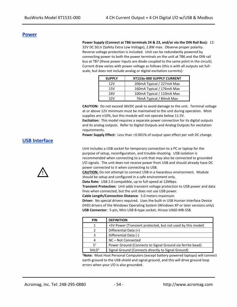
BusWorks Model XT1531-000
4 CH Current Output + 4 CH Digital I/O w/USB & Modbus
Acromag, Inc. Tel: 248-295-0880 - 54 - http://www.acromag.com
- 54 - http://www.acromag.com
Power
Power Supply (Connect at TB6 terminals 24 & 23, and/or via the DIN Rail Bus): 12-32V DC SELV (Safety Extra Low Voltage), 2.8W max. Observe proper polarity. Reverse voltage protection is included. Unit can be redundantly powered by connecting power to both the power terminals on the unit at TB6 and the DIN rail bus at TB7 (these power inputs are diode-coupled to the same point in the circuit). Current draw varies with power voltage as follows (this is with all outputs set full-scale, but does not include analog or digital excitation currents):
SUPPLY XT153x-000 SUPPLY CURRENT
12V 206mA Typical / 227mA Max
15V 160mA Typical / 176mA Max
24V 100mA Typical / 110mA Max
32V 76mA Typical / 84mA Max CAUTION: Do not exceed 36VDC peak to avoid damage to the unit. Terminal voltage at or above 12V minimum must be maintained to the unit during operation. Most supplies are ±10%, but this module will not operate below 11.5V. Excitation: This model requires a separate power connection for its digital outputs and its analog outputs. Refer to Digital Outputs and Analog Outputs for excitation requirements.
Power Supply Effect: Less than 0.001% of output span effect per volt DC change.
USB Interface
Unit includes a USB socket for temporary connection to a PC or laptop for the purpose of setup, reconfiguration, and trouble-shooting. USB isolation is recommended when connecting to a unit that may also be connected to grounded I/O signals. The unit does not receive power from USB and should already have DC power connected to it when connecting to USB. CAUTION: Do not attempt to connect USB in a hazardous environment. Module should be setup and configured in a safe environment only. Data Rate: USB 2.0 compatible, up to full-speed at 12Mbps. Transient Protection: Unit adds transient voltage protection to USB power and data lines when connected, but the unit does not use USB power. Cable Length/Connection Distance: 5.0 meters maximum. Driver: No special drivers required. Uses the built-in USB Human Interface Device (HID) drivers of the Windows Operating System (Windows XP or later versions only). USB Connector: 5-pin, Mini USB B-type socket, Hirose UX60-MB-5S8.
PIN DEFINITION
1 +5V Power (Transient protected, but not used by this model)
2 Differential Data (+)
3 Differential Data (-)
4 NC – Not Connected
51 Power Ground (Connects to Signal Ground via ferrite bead)
SHLD1 Signal Ground (Connects directly to Signal Ground) 1Note: Most Host Personal Computers (except battery powered laptops) will connect earth ground to the USB shield and signal ground, and this will drive ground loop errors when your I/O is also grounded.
!
BusWorks Model XT1531-000
4 CH Current Output + 4 CH Digital I/O w/USB & Modbus
Acromag, Inc. Tel: 248-295-0880 - 55 - http://www.acromag.com
- 55 - http://www.acromag.com
USB Interface…
Transient Protection: Unit adds transient voltage protection to USB power and data lines when connected, but the unit does not use USB power. USB Cable Length/Connection Distance: 5.0 meters maximum. IMPORTANT – USB Isolation is recommended: The outputs of these modules are isolated from each network port and DC power, but the output ground is also common to its USB connection. Most Personal computers (except DC powered laptops) connect their USB signal and shield ground to earth ground. Without a USB isolator, an earth grounded USB connection could drive a ground loop with any earth ground also applied at an output, which might interfere with operation. For this reason, we recommend that you always use a USB isolator when making a USB connection to prevent a potential ground loop from affecting performance. Otherwise, in the absence of USB isolation, a battery powered laptop could be used to connect to the unit, as the laptop does not normally connect to earth ground.
Ethernet Interface
To communicate with any network device over Ethernet, you must either set your network interface to a valid IP address in the address domain of the device, or set the address of the device to an address in the domain of your network interface. This model allows you to easily set its network IP address via a USB connection, avoiding this hassle.
Connector: Dual, shielded RJ-45 sockets, 8-pin, 10BaseT/100BaseTX. The metal shield circuit of the network connectors is isolated and capacitively coupled to the input power minus terminal via an isolation capacitor. Network-to-Network Isolation: Network ports are additionally isolated from each other and will withstand a 1000VAC dielectric strength test for 1 minute without breakdown. Wiring: Unit includes auto-crossover for MDI or MDI-X cables. Protocol: Modbus TCP/IP w/USB Configuration. IP Address: Default mode static IP address is 192.168.1.100. Port: Up to 10 sockets supported, uses port 502 (reserved for Modbus). Data Rate: Auto-sensed, 10Mbps or 100Mbps. Duplex: Auto-negotiated, Full or Half Duplex. Compliance: IEEE 802.3, 802.3u, 802.3x. Modbus TCP/IP Protocol Support: Up to 10 sockets may be selected for Modbus TCP/IP. The unit includes a built-in web page for ID on the network using a standard web-browser, but configuration of the unit is only possible using configuration software running on a Windows PC and connected via USB. Communication Distance: The distance between two devices on an Ethernet network is generally limited to 100 meters using recommended copper cable. Distances may be extended using hubs, switches, or fiber optic transmission. However, the total round trip delay time must not exceed 512 bit times for Ethernet collision detection to work properly. Port Status Indicator: Yellow LED of the network connector indicates network activity--Ethernet connection is busy and traffic is present. Address: The module’s IP address can be preset (static) by the user via USB. At startup, it can be loaded from internal non-volatile memory, or it can be automatically acquired via a network server using DHCP (Dynamic Host Configuration Protocol).
BusWorks Model XT1531-000
4 CH Current Output + 4 CH Digital I/O w/USB & Modbus
Acromag, Inc. Tel: 248-295-0880 - 56 - http://www.acromag.com
- 56 - http://www.acromag.com
Enclosure & Physical A general purpose plastic enclosure for mounting on 35mm “T-type” DIN rail.
Dimensions: Width = 22.5mm (0.9 inches), Length = 114.5mm (4.51 inches), Depth = 99.0mm (3.90 inches). Refer to Mechanical Dimensions drawing. I/O Connectors: Removable plug-in type terminal blocks rated for 12A/250V; AWG #26-12, stranded or solid copper wire. Program Connector: 5-pin, Mini USB B-type socket, Hirose UX60-MB-5S8. Case Material: Self-extinguishing polyamide, UL94 V-0 rated, color light gray. General purpose NEMA Type 1 enclosure. Circuit Board: Military grade fire-retardant epoxy glass per IPC-4101/98. DIN-Rail Mounting: Unit is normally mounted to 35x15mm, T-type DIN rails. Refer to the DIN Rail Mounting & Removal section for more details. IMPORTANT: For ambient operation above 50°C, space units apart to aide cooling. Module is intended to be mounted upright on a horizontal DIN rail, allowing cool air to enter in through the bottom vents and warm air to exhaust out the top vents. Above 50°C, a space of at least 20mm between modules should be maintained to aide cooling in this manner. Shipping Weight: 0.5 pounds (0.22 Kg) packed.
Environmental
WARNING: This is a Class A product. In a domestic environment, this product may cause radio interference in which the user may be required to take adequate measures. Refer to the EMI Filter Installation drawing in the Electrical Connections section of this manual to install ferrite cable clamps that help to reduce radiated emissions. The use of low EMI double-shielded Ethernet cable is also helpful in curbing emissions.
These limits represent the minimum requirements of the applicable standard, but this product has typically been tested to comply with higher standards in some cases.
Operating Temperature: -40C to +60C (-40F to +140F).
Storage Temperature: -40C to +85C (-40F to +185F). Relative Humidity: 5 to 95%, non-condensing. Isolation: I/O channels (analog and digital channels, excitation, and USB as a group), the network (each of two ports), and input power circuits are all isolated from each other for common-mode voltages up to 250VAC, or 354V DC off DC power ground, on a continuous basis (will withstand 1500VAC dielectric strength test for one minute without breakdown). This complies with test requirements of ANSI/ISA-82.01-1988 for the voltage rating specified. The network ports will withstand a 1000VAC dielectric strength test port-to-port for one minute without breakdown. Installation Category: Suitable for installation in a Pollution Degree 2 environment with an Installation Category (Over-voltage Category) II rating per IEC 1010-1 (1990). Shock & Vibration Immunity: Conforms to: IEC 60068-2-6: 10-500 Hz, 4G, 2 Hours/axis, for sinusoidal vibration; IEC 60068-2-64: 10-500 Hz, 4G-rms, 2 Hours/axis , for random vibration, and IEC 60068-2-27: 25G, 11ms half-sine, 18 shocks at 6 orientations, for mechanical shock. Electromagnetic Compatibility (EMC) Minimum Immunity per BS EN 61000-6-2: 1) Electrostatic Discharge Immunity (ESD), per IEC 61000-4-2. 2) Radiated Field Immunity (RFI), per IEC 61000-4-4. 3) Electrical Fast Transient Immunity (EFT), per IEC 61000-4-4. 4) Surge Immunity, per IEC 61000-4-5. 5) Conducted RF Immunity (CRFI), per IEC 61000-4-6. This is a Class A Product with Emissions per BS EN 61000-6-4: 1) Enclosure Port, per CISPR 16. 2) Low Voltage AC Mains Port, per CISPR 16.
3) Telecom / Network Port, per CISPR 22.
BusWorks Model XT1531-000
4 CH Current Output + 4 CH Digital I/O w/USB & Modbus
Acromag, Inc. Tel: 248-295-0880 - 57 - http://www.acromag.com
- 57 - http://www.acromag.com
Agency Approvals Electromagnetic Compatibility (EMC): CE marked, per EMC Directive 2004/108/EC.
Consult Factory. Safety Approvals: UL Listed (USA & Canada). Hazardous Locations – Class I, Division 2, Groups A, B, C, D Hazardous Location or Nonhazardous Locations only. These devices are open-type devices that are to be installed in an enclosure suitable for the environment. Consult Factory.
ATEX Certified: Model XT1531-000 is ATEX Certified for Explosive Atmospheres per ATEX Directive 94/9/EC which complies with standards BS EN 60079-0:2012 & BS EN 60079-15:2010.
II 3 G Ex nA IIC T4 Gc -40oC ≤ Ta ≤ +60oC
DEMKO 15 ATEX 1561X
X = Special Conditions
1) The equipment shall only be used in an area of not more than pollution degree 2, as defined in EN 60664-1.
2) The equipment shall be installed in an enclosure that provides a degree of protection not less than IP 54 and only accessible with the use of a tool in accordance with EN 60079-15.
3) Transient protection shall be provided that is set at a level not exceeding 140 % of the peak rated voltage value at the supply terminals to the equipment.
Reliability Prediction Reliability Prediction
MTBF (Mean Time Between Failure): MTBF in hours using MIL-HDBK-217F, FN2. Per MIL-HDBK-217, Ground Benign, Controlled, GBGC
XT1531-000 MTBF (Hours) MTBF (Years) Failure Rate (FIT)
25°C 445,034 hrs 50.8 years 2,247
40°C 335,836 hrs 38.3 years 2,978
Configuration Controls
Software Configuration Only via USB Although this module normally operates using Modbus TCP/IP over Ethernet, it can only be setup, calibrated, and configured via USB. This is convenient since you do not have to already know its IP address setting, or set your IP address to a compatible domain address, in order to talk to it. Its behavior as a 4 channel analog output and 4 channel digital I/O module is set using a temporary USB connection to a host computer or laptop running a Windows-compatible configuration software program specific to the model. This software provides the framework for digital control of all configuration & calibration parameters, and this information is stored in non-volatile memory.
LED Indicators: RUN (Green) – Located at front panel. Constant ON if power is on and unit is OK. Flashes ON/OFF during initialization, or if flashing continuously, it may indicate a firmware issue.
BusWorks Model XT1531-000
4 CH Current Output + 4 CH Digital I/O w/USB & Modbus
Acromag, Inc. Tel: 248-295-0880 - 58 - http://www.acromag.com
- 58 - http://www.acromag.com
ST (Yellow) – Located at front panel. Turns ON if any input signal is over/under range. ACT (Yellow) – Located on the RJ45 port connector itself. Indicates Ethernet activity--the Ethernet connection is busy and traffic is present. Refer to Configuration Step-by-Step in the Technical Reference section of this manual for detailed information on available software control of this model.
REVISION HISTORY
The following table shows the revision history for this document:
Release Date Version EGR/DOC Description of Revision
26 AUG 14 A BC/ARP Updated Initial Release.
13 OCT 14 B BC/ARP Add UL approvals (removed pending) per 14K010, added MTBF data.
06 APR 15 C FJM/ARP Shows terminals 11 and 12 with the incorrect polarity. Added DIN rail ground warning per Rob Frewald.
15-OCT-2015 D CAP/ARP Added ATEX symbols / statements.
22-AUG-2016 E CAP/MJO Corrected “Circuit Board” specification.
13 NOV 2017 F FJM/ARP Reference Configuration Software without the revision.