Embed Size (px)
Citation preview

Notification
Appliances
Hazard
ous Lo
cation
Devices
Do
or H
olders &
Relays
Initiating D
evicesE
ST2
Analog C
ontrol
ES
T2
Submittal Guide
EST2 Life Safety SystemNetworkable control with voice audio for medium sized applications
E S T B R A N D L I F E S A F E T Y & C O M M U N I C A T I O N S F R O M E D W A R D SS
e e w h a t ' s p o s s i b l e n o w . . .


Notification
Appliances
Hazard
ous Lo
cation
Devices
Do
or H
olders &
Relays
Initiating D
evicesE
ST2
Analog C
ontrol
Project: ___________________________
Contact: ___________________________
Date: ___________________________
Thank you for giving us the opportunity to provide this submittal for an EST2
Life Safety System. EST2 combines intelligent detection with technologically
advanced networking and audio capabilities. Together these innovations offer
unsurpassed stability, reliability, and flexibility.
This guide provides a summary of these innovations and includes a
comprehensive presentation of related system components and devices.
Products we are submitting for your consideration are indicated by a
checkmark in the margins of the pages that follow.
More detailed information can be found in individual data sheets dedicated
to each product. All these sheets, along with guide specifications and other
useful product information, are available electronically on our LifeLines
CD-ROM. This exhaustive collection of life safety related literature is fully
searchable and includes a utility for printing multiple data sheets.
Thank you for giving us the opportunity to provide this submittal. Please do
not hesitate to contact us should you require further information.
_____________________________

Notification
Appliances
Hazard
ous Lo
cation
Devices
Do
or H
olders &
Relays
Initiating D
evicesE
ST2
Analog C
ontrol
vii
Submittal Guide
EST2 Life Safety SystemNetworkable control with voice audio for medium sized applications

EST2 Submittal GuideNetworkable control with voice audio for medium sized applications
Copyright © 2010 UTC Fire and Security All rights reserved.
8985 Town Center Parkway, Bradenton, FL 34202
85005-0105, Issue 7.1
Wiring diagrams provided herein are for information and reference only and are not to be used for installation pur-poses. Consult the appropriate installation documents for wiring and configuration details.
This guidebook is for information only and is not intended as a substitute for verbatim legislated requirements. For authoritative specifications regarding the application of life safety, security, and access control systems, consult
current editions of applicable codes and standards. For authoritative interpretation of those codes and standards, consult your local authority having jurisdiction.
While every effort has been made to ensure the accuracy and completeness of this guidebook, the authors and publishers assume no responsibility for errors, inaccuracies, omissions, or any inconsistencies herein.
EST, QuickStart, Genesis Series, and Signature Series are trademarks of UTC Fire and Security.
Also from Edwards:
85001-0541: Handbook of Visual Notification Appliances for Fire Alarm ApplicationsA practical guide to regulatory compliance
85001-0542: Glossary of Fire Alarm and Security TerminologyA desk reference for life safety and security professionals
85001-0582: Remote Booster Power Supply Application GuideA summary of typical wiring and configuration for everyday and advanced applications
85010-0139: Installer’s Wire GuideA concise pocket reference to wire and cable requirements for Edwards products and systems
85005-0132: iO Series Submittal GuideIntelligent fire alarm solutions for small buildings
85005-0115” QuickStart Submittal GuideIntelligent/conventional life safety for small to mid-sized applications
85010-0099: EST3 Submittal GuideIntelligent control for large and medium sized applications
Intelligent Analog Initiating Devices 17Smoke Detectors ........................................................... 18Detector Bases ............................................................. 19Duct Detectors ............................................................... 20Input/Output Modules ................................................... 20Input/Output Motherboards ............................................ 24Releasing Module ........................................................... 25Pull Stations .................................................................. 26Intelligent Audio Amplifiers .............................................. 27Intelligent Power Supplies ............................................... 27Accessories ................................................................... 28
Notification Appliances 31Wall Horns, Strobes and Chimes .................................... 33Wall Speakers and Speaker/strobes ............................... 34Signal Master ................................................................. 35Ceiling Horns, Speakers and Strobes ............................. 35Harsh Environment Signals ............................................. 36Audible Signals ............................................................... 37Audio System ................................................................. 38Firefighers’ Telephones ................................................... 39Bell Strobe Plates ........................................................... 40Mounting Accessories ................................................... 40
Hazardous Location Devices 41Hazardous Classifications ............................................... 41Weather/Explosion Proof Heat Detectors ........................ 42Hazardous Location Fire Alarm Station ........................... 42Hazardous Location Strobes, Bells and Horns ................ 43
Door Holders & Relays 44Door Holders .................................................................. 44Relays ............................................................................ 44SPDT Relays .................................................................. 45
Index 46
EST2 Analog 1System configuration ........................................................ 2Main control and display ................................................... 5Audio components ........................................................... 6Power supplies ................................................................. 8Display and remote annunciation .................................... 10Communciations ............................................................ 14Accessories .................................................................... 15Wallboxes and cabinets .................................................. 16
ix
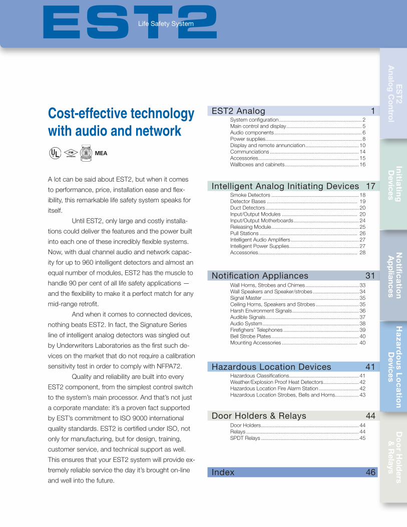
A lot can be said about EST2, but when it comes
to performance, price, installation ease and flex-
ibility, this remarkable life safety system speaks for
itself.
Until EST2, only large and costly installa-
tions could deliver the features and the power built
into each one of these incredibly flexible systems.
Now, with dual channel audio and network capac-
ity for up to 960 intelligent detectors and almost an
equal number of modules, EST2 has the muscle to
handle 90 per cent of all life safety applications —
and the flexibility to make it a perfect match for any
mid-range retrofit.
And when it comes to connected devices,
nothing beats EST2. In fact, the Signature Series
line of intelligent analog detectors was singled out
by Underwriters Laboratories as the first such de-
vices on the market that do not require a calibration
sensitivity test in order to comply with NFPA72.
Quality and reliability are built into every
EST2 component, from the simplest control switch
to the system’s main processor. And that’s not just
a corporate mandate: it’s a proven fact supported
by EST’s commitment to ISO 9000 international
quality standards. EST2 is certified under ISO, not
only for manufacturing, but for design, training,
customer service, and technical support as well.
This ensures that your EST2 system will provide ex-
tremely reliable service the day it’s brought on-line
and well into the future.
Cost-effective technology with audio and network
No
tific
atio
n A
pp
liancesH
aza
rdo
us L
oc
atio
n D
evicesD
oo
r Ho
lders
& R
elaysIn
itiatin
g
Devices
ES
T2
Analo
g C
ontro
l
EST2Life Safety System

Notification
Appliances
Hazard
ous Lo
cation
Devices
Do
or H
olders &
Relays
Initiating D
evicesE
ST2
Analog C
ontrol
1
EST2Analog Control
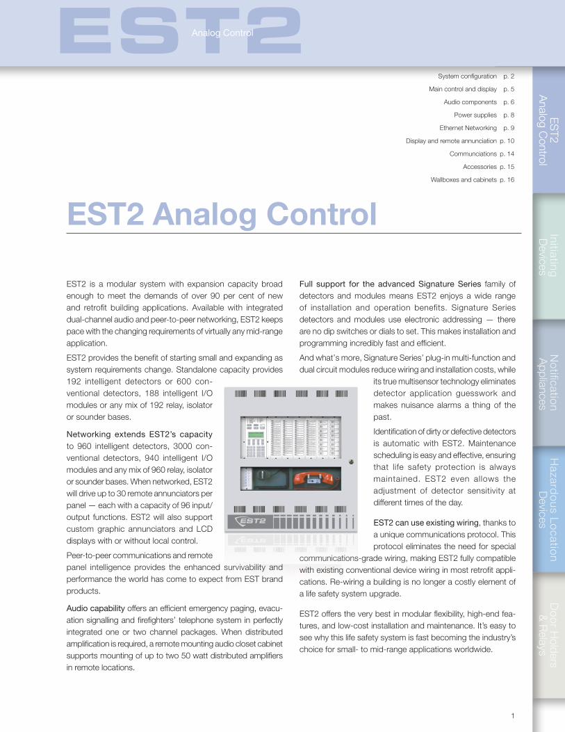
EST2 is a modular system with expansion capacity broad enough to meet the demands of over 90 per cent of new and retrofit building applications. Available with integrated dual-channel audio and peer-to-peer networking, EST2 keeps pace with the changing requirements of virtually any mid-range application.
EST2 provides the benefit of starting small and expanding as system requirements change. Standalone capacity provides 192 intelligent detectors or 600 con-ventional detectors, 188 intelligent I/O modules or any mix of 192 relay, isolator or sounder bases.
Networking extends EST2’s capacity to 960 intelligent detectors, 3000 con-ventional detectors, 940 intelligent I/O modules and any mix of 960 relay, isolator or sounder bases. When networked, EST2 will drive up to 30 remote annunciators per panel — each with a capacity of 96 input/output functions. EST2 will also support custom graphic annunciators and LCD displays with or without local control.
Peer-to-peer communications and remote panel intelligence provides the enhanced survivability and performance the world has come to expect from EST brand products.
Audio capability offers an efficient emergency paging, evacu-ation signalling and firefighters’ telephone system in perfectly integrated one or two channel packages. When distributed amplification is required, a remote mounting audio closet cabinet supports mounting of up to two 50 watt distributed amplifiers in remote locations.
Full support for the advanced Signature Series family of detectors and modules means EST2 enjoys a wide range of installation and operation benefits. Signature Series detectors and modules use electronic addressing — there are no dip switches or dials to set. This makes installation and programming incredibly fast and efficient.
And what’s more, Signature Series’ plug-in multi-function and dual circuit modules reduce wiring and installation costs, while
its true multisensor technology eliminates detector application guesswork and makes nuisance alarms a thing of the past.
Identification of dirty or defective detectors is automatic with EST2. Maintenance scheduling is easy and effective, ensuring that life safety protection is always maintained. EST2 even allows the adjustment of detector sensitivity at different times of the day.
EST2 can use existing wiring, thanks to a unique communications protocol. This protocol eliminates the need for special
communications-grade wiring, making EST2 fully compatible with existing conventional device wiring in most retrofit appli-cations. Re-wiring a building is no longer a costly element of a life safety system upgrade.
EST2 offers the very best in modular flexibility, high-end fea-tures, and low-cost installation and maintenance. It’s easy to see why this life safety system is fast becoming the industry’s choice for small- to mid-range applications worldwide.
EST2 Analog Control
System configuration p. 2
Main control and display p. 5
Audio components p. 6
Power supplies p. 8
Ethernet Networking p. 9
Display and remote annunciation p. 10
Communciations p. 14
Accessories p. 15
Wallboxes and cabinets p. 16
ES
T2
Ana
log
Con
trol
2
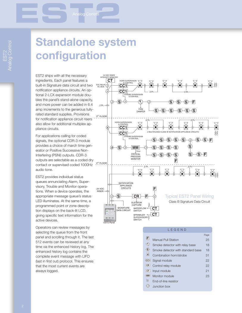
EST2 ships with all the necessary ingredients. Each panel features a built-in Signature data circuit and two notification appliance circuits. An op-tional 2-LCX expansion module dou-bles the panel’s stand-alone capacity, and more power can be added in 6.4 amp increments to the generous fully-rated standard supplies. Provisions for notification appliance circuit risers also allow for additional multiplex ap-pliance circuits.
For applications calling for coded signals, the optional CDR-3 module provides a choice of march time gen-erator or Positive Successive Non-Interfering (PSNI) outputs. CDR-3 outputs are selectable as a coded dry contact or supervised coded 1000Hz audio tone.
EST2 provides individual status queues annunciating Alarm, Super-visory, Trouble and Monitor opera-tions. When a device operates, the appropriate message queue’s status LED illuminates. At the same time, a programmed point or zone descrip-tion displays on the back-lit LCD, giving specific text information for the active devices.
Operators can review messages by selecting the queue from the front panel and scrolling through it. The last 512 events can be reviewed at any time via the enhanced history log. The enhanced history log contains the complete event message with LIFO (last in first out) protocol. This ensures that the most current events are always logged.
Standalone system configuration
L E G E N D
Page
J
S
R
S
S
S
S S S
J
J
S
S
S
S S
S
S S
S
S
S S
S S
S
S
S
S
S
S S
S S
F
EDWARDS SYSTEMS TECHNOLOGY
J
J
J
J
F
F
F
24 VDCRISER
2 Pr.2 Pr.
HORN SUPERVISION& CONTROL
HORN SUPERVISION& CONTROL
STROBE SUPERVISION& CONTROL
STROBE SUPERVISION& CONTROL
24 VDC RISERINTEGRITY MONITOR
EOL RELAYIN J BOX
2 Pr.
2 Pr.
2 Pr. 2 Pr.
2 Pr.
2 FLOORND
3 FLOORRD
SIGNATUREDATA CIRCUIT
EST2 Panel
J
CC1
CC1
CC1
CC1
J
J
S
CT
J
MM
CRITICALPROCESSMONITOR
FIREDAMPER
F
F
CT
CT
JCR
WATERFLOWSWITCH
ELEVATORCAPTURE
SPRINKLERSUPERVISORYSWITCH
2 MULTIPLEXED CLASS 'B' NOTIFICATION APPLIANCE CIRCUITS
NOTIFICATIONAPPLIANCECIRCUITS
Manual Pull Station 25
J
S
R
S
S
S
S S S
J
J
S
S
S
S S
S
S S
S
S
S S
S S
S
S
S
S
S
S S
S S
F
EDWARDS SYSTEMS TECHNOLOGY
J
J
J
J
F
F
F
24 VDCRISER
2 Pr.2 Pr.
HORN SUPERVISION& CONTROL
HORN SUPERVISION& CONTROL
STROBE SUPERVISION& CONTROL
STROBE SUPERVISION& CONTROL
24 VDC RISERINTEGRITY MONITOR
EOL RELAYIN J BOX
2 Pr.
2 Pr.
2 Pr. 2 Pr.
2 Pr.
2 FLOORND
3 FLOORRD
SIGNATUREDATA CIRCUIT
EST2 Panel
J
CC1
CC1
CC1
CC1
J
J
S
CT
J
MM
CRITICALPROCESSMONITOR
FIREDAMPER
F
F
CT
CT
JCR
WATERFLOWSWITCH
ELEVATORCAPTURE
SPRINKLERSUPERVISORYSWITCH
2 MULTIPLEXED CLASS 'B' NOTIFICATION APPLIANCE CIRCUITS
NOTIFICATIONAPPLIANCECIRCUITS
Smoke detector with relay base 18
J
S
R
S
S
S
S S S
J
J
S
S
S
S S
S
S S
S
S
S S
S S
S
S
S
S
S
S S
S S
F
EDWARDS SYSTEMS TECHNOLOGY
J
J
J
J
F
F
F
24 VDCRISER
2 Pr.2 Pr.
HORN SUPERVISION& CONTROL
HORN SUPERVISION& CONTROL
STROBE SUPERVISION& CONTROL
STROBE SUPERVISION& CONTROL
24 VDC RISERINTEGRITY MONITOR
EOL RELAYIN J BOX
2 Pr.
2 Pr.
2 Pr. 2 Pr.
2 Pr.
2 FLOORND
3 FLOORRD
SIGNATUREDATA CIRCUIT
EST2 Panel
J
CC1
CC1
CC1
CC1
J
J
S
CT
J
MM
CRITICALPROCESSMONITOR
FIREDAMPER
F
F
CT
CT
JCR
WATERFLOWSWITCH
ELEVATORCAPTURE
SPRINKLERSUPERVISORYSWITCH
2 MULTIPLEXED CLASS 'B' NOTIFICATION APPLIANCE CIRCUITS
NOTIFICATIONAPPLIANCECIRCUITS
Smoke detector with standard base 18
J
S
R
S
S
S
S S S
J
J
S
S
S
S S
S
S S
S
S
S S
S S
S
S
S
S
S
S S
S S
F
EDWARDS SYSTEMS TECHNOLOGY
J
J
J
J
F
F
F
24 VDCRISER
2 Pr.2 Pr.
HORN SUPERVISION& CONTROL
HORN SUPERVISION& CONTROL
STROBE SUPERVISION& CONTROL
STROBE SUPERVISION& CONTROL
24 VDC RISERINTEGRITY MONITOR
EOL RELAYIN J BOX
2 Pr.
2 Pr.
2 Pr. 2 Pr.
2 Pr.
2 FLOORND
3 FLOORRD
SIGNATUREDATA CIRCUIT
EST2 Panel
J
CC1
CC1
CC1
CC1
J
J
S
CT
J
MM
CRITICALPROCESSMONITOR
FIREDAMPER
F
F
CT
CT
JCR
WATERFLOWSWITCH
ELEVATORCAPTURE
SPRINKLERSUPERVISORYSWITCH
2 MULTIPLEXED CLASS 'B' NOTIFICATION APPLIANCE CIRCUITS
NOTIFICATIONAPPLIANCECIRCUITS
Combination horn/strobe 31
J
S
R
S
S
S
S S S
J
J
S
S
S
S S
S
S S
S
S
S S
S S
S
S
S
S
S
S S
S S
F
EDWARDS SYSTEMS TECHNOLOGY
J
J
J
J
F
F
F
24 VDCRISER
2 Pr.2 Pr.
HORN SUPERVISION& CONTROL
HORN SUPERVISION& CONTROL
STROBE SUPERVISION& CONTROL
STROBE SUPERVISION& CONTROL
24 VDC RISERINTEGRITY MONITOR
EOL RELAYIN J BOX
2 Pr.
2 Pr.
2 Pr. 2 Pr.
2 Pr.
2 FLOORND
3 FLOORRD
SIGNATUREDATA CIRCUIT
EST2 Panel
J
CC1
CC1
CC1
CC1
J
J
S
CT
J
MM
CRITICALPROCESSMONITOR
FIREDAMPER
F
F
CT
CT
JCR
WATERFLOWSWITCH
ELEVATORCAPTURE
SPRINKLERSUPERVISORYSWITCH
2 MULTIPLEXED CLASS 'B' NOTIFICATION APPLIANCE CIRCUITS
NOTIFICATIONAPPLIANCECIRCUITS
Signal module 22
J
S
R
S
S
S
S S S
J
J
S
S
S
S S
S
S S
S
S
S S
S S
S
S
S
S
S
S S
S S
F
EDWARDS SYSTEMS TECHNOLOGY
J
J
J
J
F
F
F
24 VDCRISER
2 Pr.2 Pr.
HORN SUPERVISION& CONTROL
HORN SUPERVISION& CONTROL
STROBE SUPERVISION& CONTROL
STROBE SUPERVISION& CONTROL
24 VDC RISERINTEGRITY MONITOR
EOL RELAYIN J BOX
2 Pr.
2 Pr.
2 Pr. 2 Pr.
2 Pr.
2 FLOORND
3 FLOORRD
SIGNATUREDATA CIRCUIT
EST2 Panel
J
CC1
CC1
CC1
CC1
J
J
S
CT
J
MM
CRITICALPROCESSMONITOR
FIREDAMPER
F
F
CT
CT
JCR
WATERFLOWSWITCH
ELEVATORCAPTURE
SPRINKLERSUPERVISORYSWITCH
2 MULTIPLEXED CLASS 'B' NOTIFICATION APPLIANCE CIRCUITS
NOTIFICATIONAPPLIANCECIRCUITS
Control relay module 22
J
S
R
S
S
S
S S S
J
J
S
S
S
S S
S
S S
S
S
S S
S S
S
S
S
S
S
S S
S S
F
EDWARDS SYSTEMS TECHNOLOGY
J
J
J
J
F
F
F
24 VDCRISER
2 Pr.2 Pr.
HORN SUPERVISION& CONTROL
HORN SUPERVISION& CONTROL
STROBE SUPERVISION& CONTROL
STROBE SUPERVISION& CONTROL
24 VDC RISERINTEGRITY MONITOR
EOL RELAYIN J BOX
2 Pr.
2 Pr.
2 Pr. 2 Pr.
2 Pr.
2 FLOORND
3 FLOORRD
SIGNATUREDATA CIRCUIT
EST2 Panel
J
CC1
CC1
CC1
CC1
J
J
S
CT
J
MM
CRITICALPROCESSMONITOR
FIREDAMPER
F
F
CT
CT
JCR
WATERFLOWSWITCH
ELEVATORCAPTURE
SPRINKLERSUPERVISORYSWITCH
2 MULTIPLEXED CLASS 'B' NOTIFICATION APPLIANCE CIRCUITS
NOTIFICATIONAPPLIANCECIRCUITS
Input module 21
J
S
R
S
S
S
S S S
J
J
S
S
S
S S
S
S S
S
S
S S
S S
S
S
S
S
S
S S
S S
F
EDWARDS SYSTEMS TECHNOLOGY
J
J
J
J
F
F
F
24 VDCRISER
2 Pr.2 Pr.
HORN SUPERVISION& CONTROL
HORN SUPERVISION& CONTROL
STROBE SUPERVISION& CONTROL
STROBE SUPERVISION& CONTROL
24 VDC RISERINTEGRITY MONITOR
EOL RELAYIN J BOX
2 Pr.
2 Pr.
2 Pr. 2 Pr.
2 Pr.
2 FLOORND
3 FLOORRD
SIGNATUREDATA CIRCUIT
EST2 Panel
J
CC1
CC1
CC1
CC1
J
J
S
CT
J
MM
CRITICALPROCESSMONITOR
FIREDAMPER
F
F
CT
CT
JCR
WATERFLOWSWITCH
ELEVATORCAPTURE
SPRINKLERSUPERVISORYSWITCH
2 MULTIPLEXED CLASS 'B' NOTIFICATION APPLIANCE CIRCUITS
NOTIFICATIONAPPLIANCECIRCUITS
Monitor module 23
J
S
R
S
S
S
S S S
J
J
S
S
S
S S
S
S S
S
S
S S
S S
S
S
S
S
S
S S
S S
F
EDWARDS SYSTEMS TECHNOLOGY
J
J
J
J
F
F
F
24 VDCRISER
2 Pr.2 Pr.
HORN SUPERVISION& CONTROL
HORN SUPERVISION& CONTROL
STROBE SUPERVISION& CONTROL
STROBE SUPERVISION& CONTROL
24 VDC RISERINTEGRITY MONITOR
EOL RELAYIN J BOX
2 Pr.
2 Pr.
2 Pr. 2 Pr.
2 Pr.
2 FLOORND
3 FLOORRD
SIGNATUREDATA CIRCUIT
EST2 Panel
J
CC1
CC1
CC1
CC1
J
J
S
CT
J
MM
CRITICALPROCESSMONITOR
FIREDAMPER
F
F
CT
CT
JCR
WATERFLOWSWITCH
ELEVATORCAPTURE
SPRINKLERSUPERVISORYSWITCH
2 MULTIPLEXED CLASS 'B' NOTIFICATION APPLIANCE CIRCUITS
NOTIFICATIONAPPLIANCECIRCUITS
End-of-line resistor
J
S
R
S
S
S
S S S
J
J
S
S
S
S S
S
S S
S
S
S S
S S
S
S
S
S
S
S S
S S
F
EDWARDS SYSTEMS TECHNOLOGY
J
J
J
J
F
F
F
24 VDCRISER
2 Pr.2 Pr.
HORN SUPERVISION& CONTROL
HORN SUPERVISION& CONTROL
STROBE SUPERVISION& CONTROL
STROBE SUPERVISION& CONTROL
24 VDC RISERINTEGRITY MONITOR
EOL RELAYIN J BOX
2 Pr.
2 Pr.
2 Pr. 2 Pr.
2 Pr.
2 FLOORND
3 FLOORRD
SIGNATUREDATA CIRCUIT
EST2 Panel
J
CC1
CC1
CC1
CC1
J
J
S
CT
J
MM
CRITICALPROCESSMONITOR
FIREDAMPER
F
F
CT
CT
JCR
WATERFLOWSWITCH
ELEVATORCAPTURE
SPRINKLERSUPERVISORYSWITCH
2 MULTIPLEXED CLASS 'B' NOTIFICATION APPLIANCE CIRCUITS
NOTIFICATIONAPPLIANCECIRCUITS
Junction box
J
S
R
S
S
S
S S S
J
J
S
S
S
S S
S
S S
S
S
S S
S S
S
S
S
S
S
S S
S S
F
EDWARDS SYSTEMS TECHNOLOGY
J
J
J
J
F
F
F
24 VDCRISER
2 Pr.2 Pr.
HORN SUPERVISION& CONTROL
HORN SUPERVISION& CONTROL
STROBE SUPERVISION& CONTROL
STROBE SUPERVISION& CONTROL
24 VDC RISERINTEGRITY MONITOR
EOL RELAYIN J BOX
2 Pr.
2 Pr.
2 Pr. 2 Pr.
2 Pr.
2 FLOORND
3 FLOORRD
SIGNATUREDATA CIRCUIT
EST2 Panel
J
CC1
CC1
CC1
CC1
J
J
S
CT
J
MM
CRITICALPROCESSMONITOR
FIREDAMPER
F
F
CT
CT
JCR
WATERFLOWSWITCH
ELEVATORCAPTURE
SPRINKLERSUPERVISORYSWITCH
2 MULTIPLEXED CLASS 'B' NOTIFICATION APPLIANCE CIRCUITS
NOTIFICATIONAPPLIANCECIRCUITS
Typical EST2 Panel WiringClass B Signature Data Circuit
EST2Analog Control
Notification
Appliances
Hazard
ous Lo
cation
Devices
Do
or H
olders &
Relays
Initiating D
evicesE
ST2
Analog C
ontrol
3
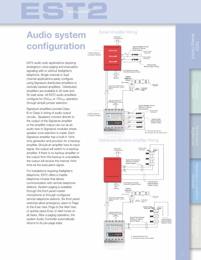
EST2 audio suits applications requiring emergency voice paging and evacuation signaling with or without firefighter’s telephone. Single channel or dual channel applications easily configure using Signature distributed amplifiers or centrally banked amplifiers. Distributed amplifiers are available in 30 watt and 50 watt sizes. All EST2 audio amplifiers configure for 25VRMS or 70VRMS operation through simple jumper selection.
Signature amplifiers provide Class B or Class A wiring of audio output circuits. Speakers connect directly to the output of the Signature amplifier or the amplifier output can run as an audio riser to Signature modules where speaker zone selection is made. Each Signature amplifier has a built-in 1kHz tone generator and provision for a backup amplifier. Should an amplifier lose its input signal, the output will switch to a backup amplifier. If there is no backup amplifier or the output from the backup is unavailable, the output will receive the internal 1kHz tone as the evacuation signal.
For installations requiring firefighter’s telephone, EST2 offers a master telephone module that allows communication with remote telephone stations. System paging is available through the front panel master microphone or through configured remote telephone stations. Six front panel switches allow emergency users to Page to the Evac riser, Page to the Alert riser, or quickly place Evac or Alert tones on all risers. After a paging operation, the system Audio Controller automatically returns to its pre-page state.
Audio system configuration
Zoned Amplifier Wiring
2
Typical Speaker Circuit25Vrms or 70VrmsAudio Outputs
UL/ULC Listed
47K EOL�
UL/ULC Listed
47K EOL�
Typical AudioReturn (Class A Only)
UL/ULC Listed
47K EOL�- +
Style Y (Class B)
TypicalTelephone
Circuit:1
1
11
2
2
2
2
2
SIGA-CC1
Typical Speaker Circuit25Vrms or 70VrmsAudio Outputs
Typical Two Channel AudioPanel interconnect 1vrms or25Vrms. PHONE
RISER OUT
To Next Device
or 47K EOLResistor
�
UL/ULC Listed
47K EOL�
Typical AudioChannel Return(Class A Only)
(+)
Signature DATA OUTTo All Signature Devices
(-)
DATA OUTTo Next Device
DATA IN
(+)
(+)
(-)
(-)
From Signature Controlleror Previous Signature Device
1
2
Twisted-Shielded Pair WireOne Twisted Pair Wire, Shield optional
SIGA-AMP
SIGA-APS
SIGA-AMP
120VAC 50/60 Hzor 220VAC 50/60Hz
120VAC 50/60 Hzor 220VAC 50/60Hz
Distributed Banked Amplifier Wiring
Typical Two Channel25Vrms or 70VrmsAudio Outputs SIGA-
CC1, CC2, or UM
SIGA-CC1, CC2, or UM
SIGA-CC1, CC2, or UM
UL/ULC Listed
47K EOL�
Typical AudioChannel Return(Class A Only)
UL/ULC Listed
47K EOL�- +
Style Y (Class B)
TypicalTelephone
Circuit:1
1
11
2
2
2
2
SIGA-CC1
Typical Two Channel25Vrms or 70VrmsAudio Outputs
Typical Two Channel AudioPanel interconnect 1vrms or25Vrms. PHONE
RISER OUT
To Next Device
or 47K EOLResistor
�
UL/ULC Listed
47K EOL�
SIGA-CC1, CC2, or UM
SIGA-CC1, CC2, or UM
SIGA-CC1, CC2, or UM
Typical AudioChannel Return(Class A Only)
SIGA-CC2
SIGA-CC2
SIGA-CC2
SIGA-CC2
SIGA-CC2
SIGA-CC2
(+)
Signature DATA OUTTo All Signature Devices
(-)
DATA OUTTo Next Device
DATA IN
(+)
(+)
(-)
(-)
From Signature Controlleror Previous Signature Device
1
2
Twisted-Shielded Pair Wire
One Twisted Pair Wire, Shield optional
EST2Analog Control
ES
T2
Ana
log
Con
trol
4
Networked system configuration
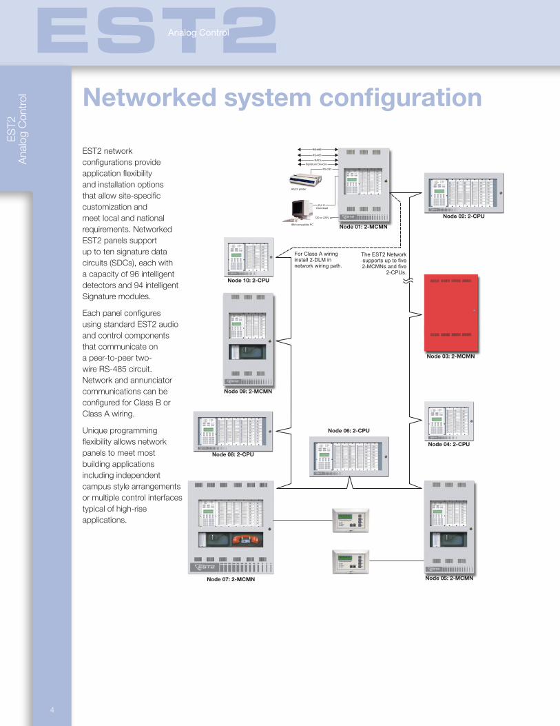
EST2 network configurations provide application flexibility and installation options that allow site-specific customization and meet local and national requirements. Networked EST2 panels support up to ten signature data circuits (SDCs), each with a capacity of 96 intelligent detectors and 94 intelligent Signature modules.
Each panel configures using standard EST2 audio and control components that communicate on a peer-to-peer two-wire RS-485 circuit. Network and annunciator communications can be configured for Class B or Class A wiring.
Unique programming flexibility allows network panels to meet most building applications including independent campus style arrangements or multiple control interfaces typical of high-rise applications.
Signature Devices
120 or 220V ac
RS-485
RS-485
NACs
IBM compatible PC
RS-232
ASCII printer
RJ-11Download
The EST2 Networksupports up to five2-MCMNs and five
2-CPUs.
For Class A wiringinstall 2-DLM innetwork wiring path.
Node 01: 2-MCMN
Node 02: 2-CPU
Node 03: 2-MCMN
Node 04: 2-CPU
Node 05: 2-MCMN
Node 06: 2-CPU
Node 07: 2-MCMN
Node 08: 2-CPU
Node 09: 2-MCMN
Node 10: 2-CPU
EST2Analog Control
SUBMIT
Notification
Appliances
Hazard
ous Lo
cation
Devices
Do
or H
olders &
Relays
Initiating D
evicesE
ST2
Analog C
ontrol
5
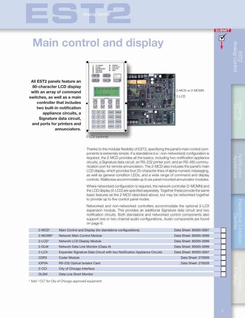
Thanks to the modular flexibility of EST2, specifiying the panel’s main control com-ponents is extremely simple. If a standalone (i.e.: non-networked) configuration is required, the 2-MCD provides all the basics, including two notification appliance circuits, a Signature data circuit, an RS-232 printer port, and an RS-485 commu-nication port for remote annunciation. The 2-MCD also includes the panel’s main LCD display, which provides four 20-character lines of alpha-numeric messaging, as well as general condition LEDs, and a wide range of command and display controls. Wallboxes accommodate up to six panel mounted annunciator modules.
Where networked configuration is required, the network controller (2-MCMN) and the LCD display (2-LCD) are specified separately. Together these provide the same basic features as the 2-MCD described above, but may be networked together to provide up to five control panel nodes.
Networked and non-networked controllers accommodate the optional 2-LCX expansion module. This provides an additional Signature data circuit and two notification circuits. Both standalone and networked control components also support one or two channel audio configurations. Audio components are found on page 6.
2-MCD* Main Control and Display (for standalone configurations) Data Sheet: 85005-0097
2-MCMN* Network Main Control Module Data Sheet: 85005-0099
2-LCD* Network LCD Display Module Data Sheet: 85005-0099
2-DLM Network Data Line Monitor (Class A) Data Sheet: 85005-0099
2-LCX Expander Signature Data Circuit with two Notification Appliance Circuits Data Sheet: 85005-0097
CDR3 Coder Module Data Sheet: 270009
IOP3A RS-232 Optical Isolator Card Data Sheet: 270039
2-CCI City of Chicago Interface
DLSM Data Line Short Monitor
* Add “-CC” for City of Chicago approved equipment
2-MCD or 2-MCMN
2-LCD
2-LCX (optional)
All EST2 panels feature an 80-character LCD display
with an array of command switches, as well as a main
controller that includes two built-in notification
appliance circuits, a Signature data circuit,
and ports for printers and annunciators.
Main control and display
EST2Analog Control
ES
T2
Ana
log
Con
trol
SUBMIT
6
EST2Analog Control
Audio components
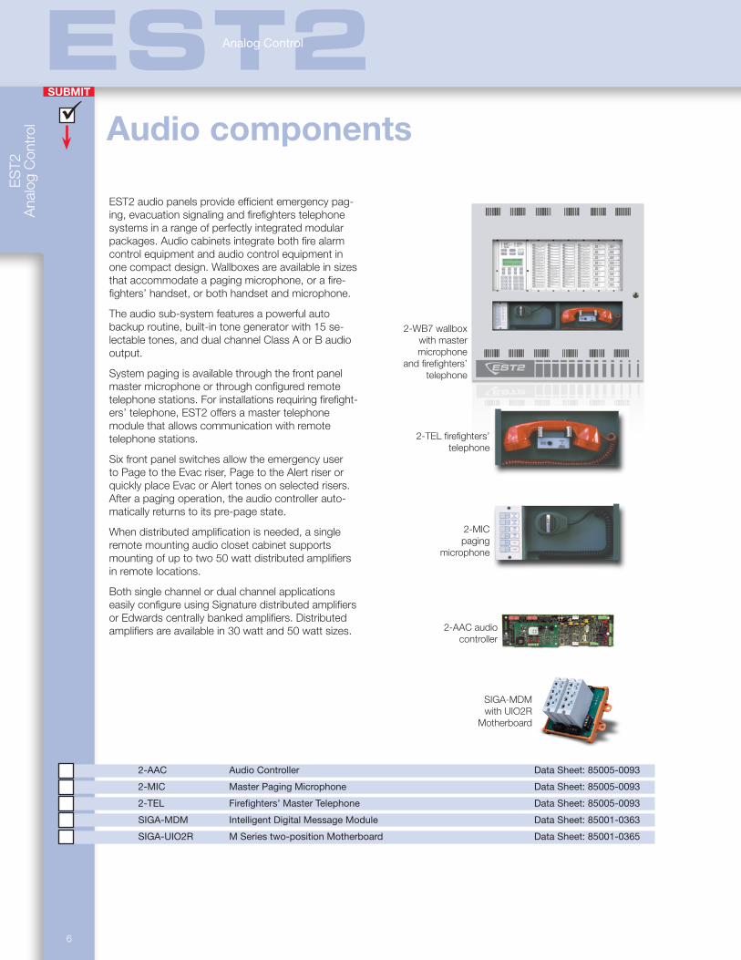
EST2 audio panels provide efficient emergency pag-ing, evacuation signaling and firefighters telephone systems in a range of perfectly integrated modular packages. Audio cabinets integrate both fire alarm control equipment and audio control equipment in one compact design. Wallboxes are available in sizes that accommodate a paging microphone, or a fire-fighters’ handset, or both handset and microphone.
The audio sub-system features a powerful auto backup routine, built-in tone generator with 15 se-lectable tones, and dual channel Class A or B audio output.
System paging is available through the front panel master microphone or through configured remote telephone stations. For installations requiring firefight-ers’ telephone, EST2 offers a master telephone module that allows communication with remote telephone stations.
Six front panel switches allow the emergency user to Page to the Evac riser, Page to the Alert riser or quickly place Evac or Alert tones on selected risers. After a paging operation, the audio controller auto-matically returns to its pre-page state.
When distributed amplification is needed, a single remote mounting audio closet cabinet supports mounting of up to two 50 watt distributed amplifiers in remote locations.
Both single channel or dual channel applications easily configure using Signature distributed amplifiers or Edwards centrally banked amplifiers. Distributed amplifiers are available in 30 watt and 50 watt sizes.
2-WB7 wallbox with master microphone
and firefighters’ telephone
2-TEL firefighters’ telephone
2-MIC paging
microphone
2-AAC audio controller
2-AAC Audio Controller Data Sheet: 85005-0093
2-MIC Master Paging Microphone Data Sheet: 85005-0093
2-TEL Firefighters’ Master Telephone Data Sheet: 85005-0093
SIGA-MDM Intelligent Digital Message Module Data Sheet: 85001-0363
SIGA-UIO2R M Series two-position Motherboard Data Sheet: 85001-0365
SIGA-MDM with UIO2R
Motherboard
SUBMIT
Notification
Appliances
Hazard
ous Lo
cation
Devices
Do
or H
olders &
Relays
Initiating D
evicesE
ST2
Analog C
ontrol
7
EST2Analog Control
To 24 VDC
From Output of
Backup Amp
To Backup Input
of Next Amp
Shield Optional
Output Return
Class A Only
Audio Output
to Speakers or
Signature device
Output Voltage
Selection Jumper
To Next
Signature Device
From Previous
Signature Device
From Channel 1
Signal Source
1Vrms or 25Vrms
To Next Amp
Channel 1 Input
To Next Amp
Channel 2 Input
From Channel 2
Signal Source
1Vrms or 25Vrms
Status LEDs
Status LEDs
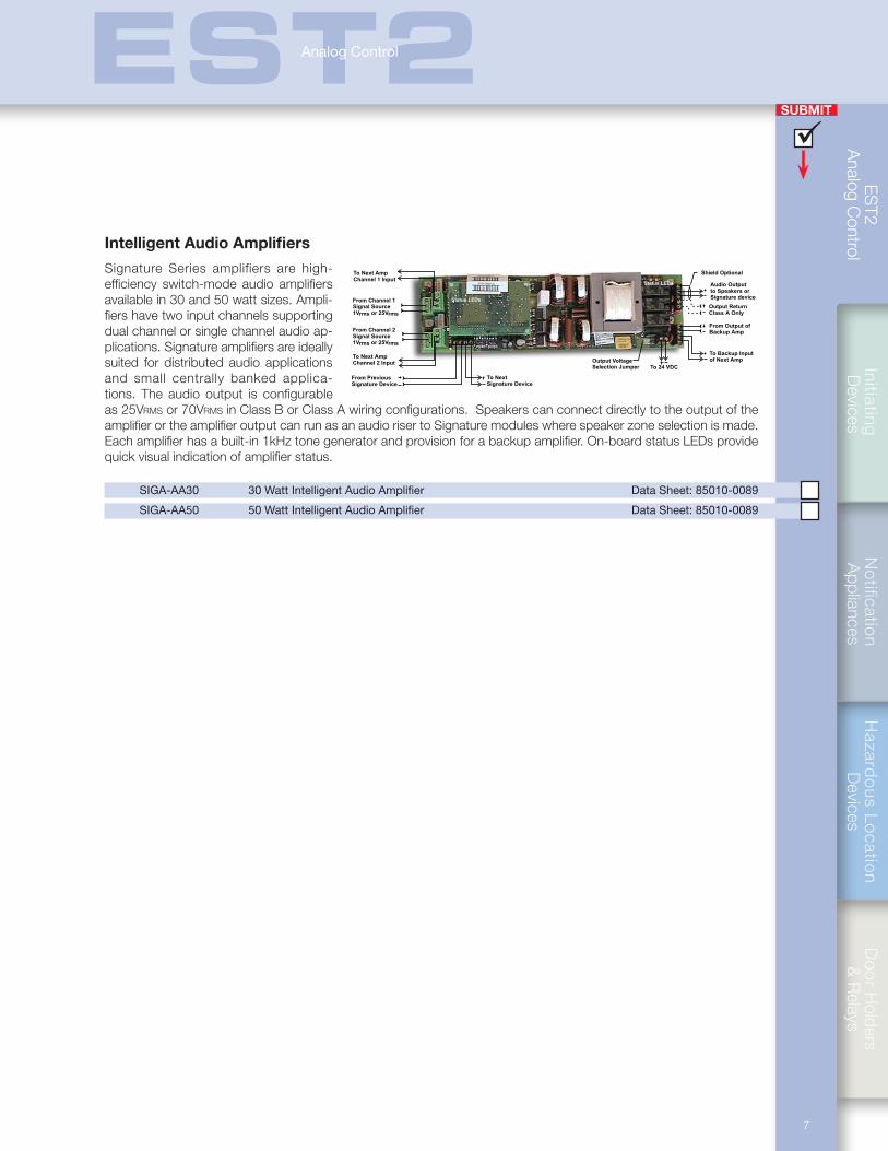
Intelligent Audio Amplifiers
Signature Series amplifiers are high-efficiency switch-mode audio amplifiers available in 30 and 50 watt sizes. Ampli-fiers have two input channels supporting dual channel or single channel audio ap-plications. Signature amplifiers are ideally suited for distributed audio applications and small centrally banked applica-tions. The audio output is configurable as 25Vrms or 70Vrms in Class B or Class A wiring configurations. Speakers can connect directly to the output of the amplifier or the amplifier output can run as an audio riser to Signature modules where speaker zone selection is made. Each amplifier has a built-in 1kHz tone generator and provision for a backup amplifier. On-board status LEDs provide quick visual indication of amplifier status.
SIGA-AA30 30 Watt Intelligent Audio Amplifier Data Sheet: 85010-0089
SIGA-AA50 50 Watt Intelligent Audio Amplifier Data Sheet: 85010-0089
ES
T2
Ana
log
Con
trol
SUBMIT
8
EST2Analog Control
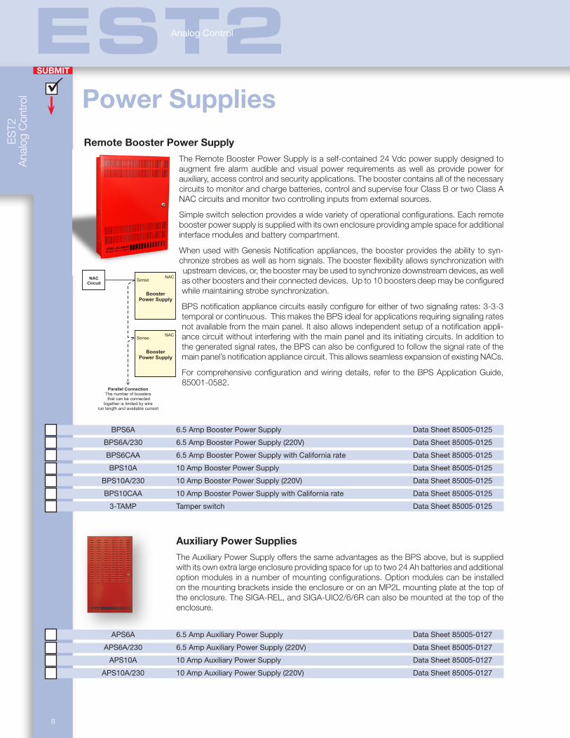
Power SuppliesRemote Booster Power Supply
The Remote Booster Power Supply is a self-contained 24 Vdc power supply designed to augment fire alarm audible and visual power requirements as well as provide power for auxiliary, access control and security applications. The booster contains all of the necessary circuits to monitor and charge batteries, control and supervise four Class B or two Class A NAC circuits and monitor two controlling inputs from external sources.
Simple switch selection provides a wide variety of operational configurations. Each remote booster power supply is supplied with its own enclosure providing ample space for additional interface modules and battery compartment.
When used with Genesis Notification appliances, the booster provides the ability to syn-chronize strobes as well as horn signals. The booster flexibility allows synchronization with upstream devices, or, the booster may be used to synchronize downstream devices, as well as other boosters and their connected devices. Up to 10 boosters deep may be configured while maintaining strobe synchronization.
BPS notification appliance circuits easily configure for either of two signaling rates: 3-3-3 temporal or continuous. This makes the BPS ideal for applications requiring signaling rates not available from the main panel. It also allows independent setup of a notification appli-ance circuit without interfering with the main panel and its initiating circuits. In addition to the generated signal rates, the BPS can also be configured to follow the signal rate of the main panel’s notification appliance circuit. This allows seamless expansion of existing NACs.
For comprehensive configuration and wiring details, refer to the BPS Application Guide, 85001-0582.
BPS6A 6.5 Amp Booster Power Supply Data Sheet 85005-0125
BPS6A/230 6.5 Amp Booster Power Supply (220V) Data Sheet 85005-0125
BPS6CAA 6.5 Amp Booster Power Supply with California rate Data Sheet 85005-0125
BPS10A 10 Amp Booster Power Supply Data Sheet 85005-0125
BPS10A/230 10 Amp Booster Power Supply (220V) Data Sheet 85005-0125
BPS10CAA 10 Amp Booster Power Supply with California rate Data Sheet 85005-0125
3-TAMP Tamper switch Data Sheet 85005-0125
Auxiliary Power Supplies
The Auxiliary Power Supply offers the same advantages as the BPS above, but is supplied with its own extra large enclosure providing space for up to two 24 Ah batteries and additional option modules in a number of mounting configurations. Option modules can be installed on the mounting brackets inside the enclosure or on an MP2L mounting plate at the top of the enclosure. The SIGA-REL, and SIGA-UIO2/6/6R can also be mounted at the top of the enclosure.
APS6A 6.5 Amp Auxiliary Power Supply Data Sheet 85005-0127
APS6A/230 6.5 Amp Auxiliary Power Supply (220V) Data Sheet 85005-0127
APS10A 10 Amp Auxiliary Power Supply Data Sheet 85005-0127
APS10A/230 10 Amp Auxiliary Power Supply (220V) Data Sheet 85005-0127
BoosterPower Supply
SenseNAC
Parallel ConnectionThe number of boostersthat can be connected
together is limited by wirerun length and available current
Parallel ConnectionThe number of boostersthat can be connected
together is limited by wirerun length and available current
Series ConnectionUp to ten boosterscan be connectedtogether
BoosterPower Supply
SenseNAC
BoosterPower Supply
SenseNACNAC
Circuit
SUBMIT
Notification
Appliances
Hazard
ous Lo
cation
Devices
Do
or H
olders &
Relays
Initiating D
evicesE
ST2
Analog C
ontrol
9
EST2Analog Control
Standard Power Supplies
All EST2 panels are available with 4.5 amp or 6.4 amp power supplies. These provide the full current rating for notification appliance circuits. Power is provided via two power limited 24Vdc sources. Additional power can be added in 6.4 amp increments. Provisions for notification appliance circuit risers allow for additional multiplex appliance circuits.
2-PPS 4.5 Amp Power Supply — 120Vac Data Sheet: 85005-0097 2-PPS/6A 6.4 Amp Power Supply — 120Vac Data Sheet: 85005-0097 2-PPS/220 4.5 Amp Power Supply — 220Vac Data Sheet: 85005-0097 2-PPS/6A-220A 6.4 Amp Power Supply — 220Vac Data Sheet: 85005-0097
To Battery
Ground
Neutral
Hot
24 VDC @ 3.2A
24 VDC @ 3.2A
SIGA OUT
SIGA IN
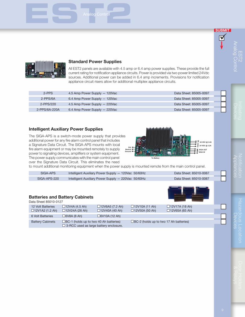
Intelligent Auxiliary Power Supplies
The SIGA-APS is a switch-mode power supply that provides additional power for any fire alarm control panel that includes a Signature Data Circuit. The SIGA-APS mounts with local fire alarm equipment or may be mounted remotely to supply power to signaling devices, amplifiers or system equipment. The power supply communicates with the main control panel over the Signature Data Circuit. This eliminates the need to mount additional monitoring equipment when the power supply is mounted remote from the main control panel.
SIGA-APS Intelligent Auxiliary Power Supply — 120Vac 50/60Hz Data Sheet: 85010-0087 SIGA-APS-220 Intelligent Auxiliary Power Supply — 220Vac 50/60Hz Data Sheet: 85010-0087
Batteries and Battery CabinetsData Sheet 85010-0127
12 Volt Batteries 12V4A (4.5 Ah) 12V6A5 (7.2 Ah) 12V10A (11 Ah) 12V17A (18 Ah) 12V1A2 (1.2 Ah) 12V24A (26 Ah) 12V40A (40 Ah) 12V50A (50 Ah) 12V65A (65 Ah)
6 Volt Batteries 6V8A (8 Ah) 6V10A (12 Ah) Battery Cabinets BC-1 (holds up to two 40 Ah batteries) BC-2 (holds up to two 17 Ah batteries) 3-RCC used as large battery enclosure.
ES
T2
Ana
log
Con
trol
SUBMIT
10
EST2Analog Control
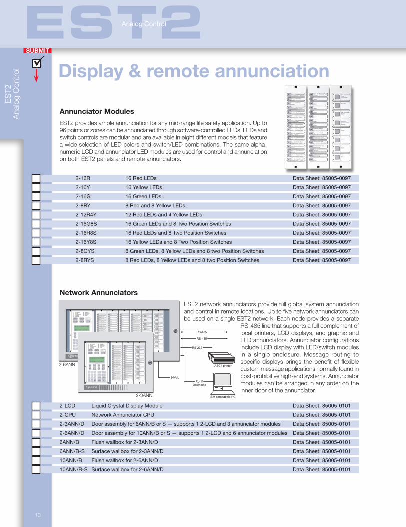
Annunciator Modules
EST2 provides ample annunciation for any mid-range life safety application. Up to 96 points or zones can be annunciated through software-controlled LEDs. LEDs and switch controls are modular and are available in eight different models that feature a wide selection of LED colors and switch/LED combinations. The same alpha-numeric LCD and annunciator LED modules are used for control and annunciation on both EST2 panels and remote annunciators.
2-16R 16 Red LEDs Data Sheet: 85005-0097
2-16Y 16 Yellow LEDs Data Sheet: 85005-0097
2-16G 16 Green LEDs Data Sheet: 85005-0097
2-8RY 8 Red and 8 Yellow LEDs Data Sheet: 85005-0097
2-12R4Y 12 Red LEDs and 4 Yellow LEDs Data Sheet: 85005-0097
2-16G8S 16 Green LEDs and 8 Two Position Switches Data Sheet: 85005-0097
2-16R8S 16 Red LEDs and 8 Two Position Switches Data Sheet: 85005-0097
2-16Y8S 16 Yellow LEDs and 8 Two Position Switches Data Sheet: 85005-0097
2-8GYS 8 Green LEDs, 8 Yellow LEDs and 8 two Position Switches Data Sheet: 85005-0097
2-8RYS 8 Red LEDs, 8 Yellow LEDs and 8 two Position Switches Data Sheet: 85005-0097
Network Annunciators
EST2 network annunciators provide full global system annunciation and control in remote locations. Up to five network annunciators can be used on a single EST2 network. Each node provides a separate
RS-485 line that supports a full complement of local printers, LCD displays, and graphic and LED annunciators. Annunciator configurations include LCD display with LED/switch modules in a single enclosure. Message routing to specific displays brings the benefit of flexible custom message applications normally found in cost-prohibitive high-end systems. Annunciator modules can be arranged in any order on the inner door of the annunciator.
2-LCD Liquid Crystal Display Module Data Sheet: 85005-0101
2-CPU Network Annunciator CPU Data Sheet: 85005-0101
2-3ANN/D Door assembly for 6ANN/B or S — supports 1 2-LCD and 3 annunciator modules Data Sheet: 85005-0101
2-6ANN/D Door assembly for 10ANN/B or S — supports 1 2-LCD and 6 annunciator modules Data Sheet: 85005-0101
6ANN/B Flush wallbox for 2-3ANN/D Data Sheet: 85005-0101
6ANN/B-S Surface wallbox for 2-3ANN/D Data Sheet: 85005-0101
10ANN/B Flush wallbox for 2-6ANN/D Data Sheet: 85005-0101
10ANN/B-S Surface wallbox for 2-6ANN/D Data Sheet: 85005-0101
Display & remote annunciation
2-6ANN
2-3ANN
RJ-11
RS-485
RS-485
IBM compatible PC
RS-232
ASCII printer
24Vdc
RJ-11Download
SUBMIT
Notification
Appliances
Hazard
ous Lo
cation
Devices
Do
or H
olders &
Relays
Initiating D
evicesE
ST2
Analog C
ontrol
11
EST2Analog Control
Smoked Plexiglas c/w Graphic
Optional 3-EVRMFModule Mounting Frame(7 EIA Panel spaces high)
BP1
Flush TrimOptional
Outer DoorSeparate Hinged
Mounting Rails
Feature Plate
Optional
or
Wallbox
LED Matrix Board
MountingHinged LED/GRAPHIC
Extrusion/Mounting
Driver Board
Chassis
24VDC FROM 3-PPS/MOR 3-BPS/M POWER RISER
FROM PREVIOUS PANELRS-485 NETWORK DATA
POWER MODULE
RS-485 NETWORK DATATO NEXT PANEL
24VDC TO NEXT
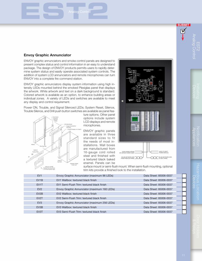
Envoy Graphic Annunciator
ENVOY graphic annunciators and smoke control panels are designed to present complex status and control information in an easy to understand package. The design of ENVOY products permits users to rapidly deter-mine system status and easily operate associated system controls. The addition of system LCD annunciators and remote microphones can turn ENVOY into a complete fire command station.
ENVOY graphic annunciators display system information using high in-tensity LEDs mounted behind the smoked Plexiglas panel that displays the artwork. White artwork and text on a dark background is standard. Colored artwork is available as an option, to enhance building areas or individual zones. A variety of LEDs and switches are available to meet any display and control requirement.
Power ON, Trouble, and Signal Silenced LEDs; System Reset, Silence, Trouble Silence, and Drill push button switches are available as panel fea-
ture options. Other panel options include system LCD displays and remote microphones.
ENVOY graphic panels are available in three standard sizes to f i t the needs of most in-stallations. Wall boxes are manufactured from 16-gauge cold rolled steel and finished with a textured black baked enamel. Panels can be surface mount or semi-flush mount. When semi-flush mounting, optional trim kits provide a finished look to the installation.
EV1 Envoy Graphic Annunciator (maximum 96 LEDs) Data Sheet: 85006-0037
EV1B EV1 Wallbox: textured black finish Data Sheet: 85006-0037
EV1T EV1 Semi-Flush Trim: textured black finish Data Sheet: 85006-0037
EV2 Envoy Graphic Annunciator (maximum 160 LEDs) Data Sheet: 85006-0037
EV2B EV2 Wallbox: textured black finish Data Sheet: 85006-0037
EV2T EV2 Semi-Flush Trim: textured black finish Data Sheet: 85006-0037
EV3 Envoy Graphic Annunciator (maximum 256 LEDs) Data Sheet: 85006-0037
EV3B EV3 Wallbox: textured black finish Data Sheet: 85006-0037
EV3T EV3 Semi-Flush Trim: textured black finish Data Sheet: 85006-0037
ES
T2
Ana
log
Con
trol
SUBMIT
12
EST2Analog Control
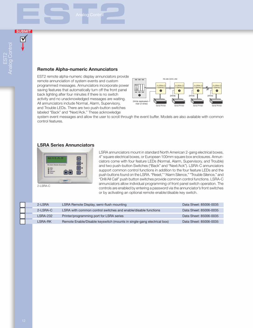
2-LSRA-C
Remote Alpha-numeric Annunciators
EST2 remote alpha-numeric display annunciators provide remote annunciation of system events and custom programmed messages. Annunciators incorporate power saving features that automatically turn off the front panel back lighting after four minutes if there is no switch activity and no unacknowledged messages are waiting. All annunciators include Normal, Alarm, Supervisory, and Trouble LEDs. There are two push-button switches labeled “Back” and “Next/Ack.” These acknowledge system event messages and allow the user to scroll through the event buffer. Models are also available with common control features.
LSRA Series Annunciators
LSRA annunciators mount in standard North American 2-gang electrical boxes, 4” square electrical boxes, or European 100mm square box enclosures. Annun-ciators come with four feature LEDs (Normal, Alarm, Supervisory, and Trouble) and two push-button Switches (“Back” and “Next/Ack”). LSRA-C annunciators support common control functions in addition to the four feature LEDs and the push buttons found on the LSRA. “Reset,” “Alarm Silence,” “Trouble Silence,” and “Drill/All Call” push button switches provide common control functions. LSRA-C annunciators allow individual programming of front panel switch operation. The controls are enabled by entering a password via the annunciator’s front switches or by activating an optional remote enable/disable key switch.
2-LSRA LSRA Remote Display, semi-flush mounting Data Sheet: 85006-0035
2-LSRA-C LSRA with common control switches and enable/disable functions Data Sheet: 85006-0035
LSRA-232 Printer/programming port for LSRA series Data Sheet: 85006-0035
LSRA-RK Remote Enable/Disable keyswitch (mounts in single-gang electrical box) Data Sheet: 85006-0035
AC POWER
DISABLE
CPU FAILTROUBLE
ALARM
SUPERVISORY GND FAULT
MONITOR TEST
RESET
DRILL
ALARM SUPVR
ACK
TRBLE MONTR
ALARMSILENCE
TROUBLESILENCE
1
4
7
2
5
8
0
3
6
9
STATUS
ENABLE
ACTIVATE RESTORE
TEST
PROGRAM
DISABLE
REPORTS
24Vdc 24Vdc 24Vdc
RS-485 DATA LINE
3 4 32
Serial Printer Serial Printer Serial Printer Serial Printer
2-LSRA(-C) 2-LSRA(-C) 2-LSRA(-C) 2-LSRA(-C)2-SMDN(C) 2-SMDN(C) 2-SMDN(C) 2-SMDN(C)
2
24Vdc dedicatedriser (2 wires)
1
SUBMIT
Notification
Appliances
Hazard
ous Lo
cation
Devices
Do
or H
olders &
Relays
Initiating D
evicesE
ST2
Analog C
ontrol
13
EST2Analog Control
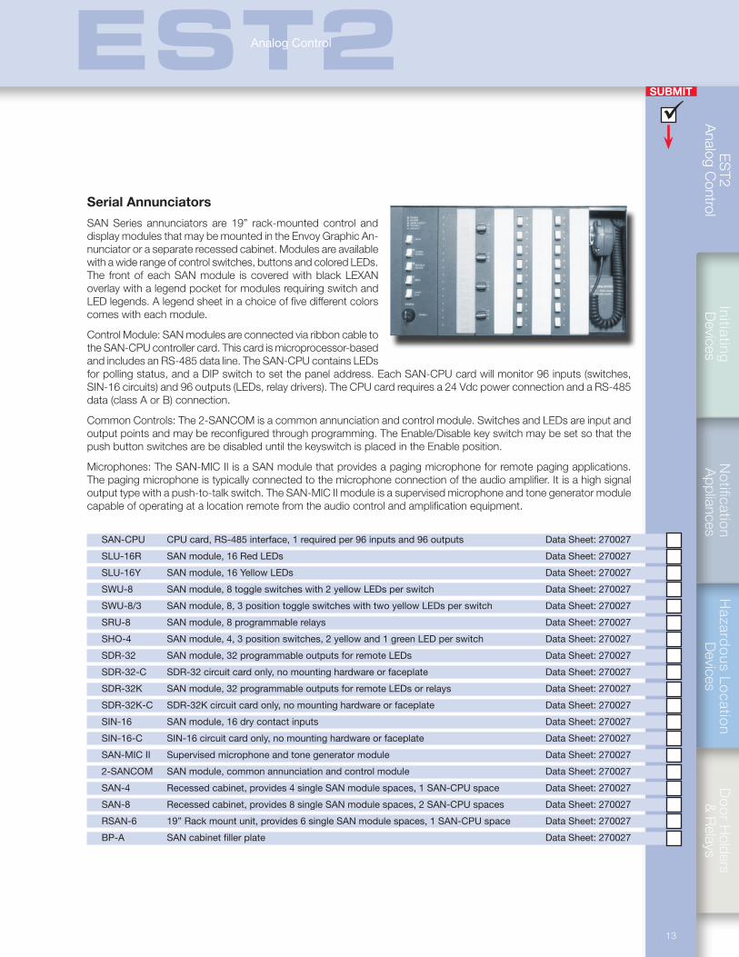
Serial Annunciators
SAN Series annunciators are 19” rack-mounted control and display modules that may be mounted in the Envoy Graphic An-nunciator or a separate recessed cabinet. Modules are available with a wide range of control switches, buttons and colored LEDs. The front of each SAN module is covered with black LEXAN overlay with a legend pocket for modules requiring switch and LED legends. A legend sheet in a choice of five different colors comes with each module.
Control Module: SAN modules are connected via ribbon cable to the SAN-CPU controller card. This card is microprocessor-based and includes an RS-485 data line. The SAN-CPU contains LEDs for polling status, and a DIP switch to set the panel address. Each SAN-CPU card will monitor 96 inputs (switches, SIN-16 circuits) and 96 outputs (LEDs, relay drivers). The CPU card requires a 24 Vdc power connection and a RS-485 data (class A or B) connection.
Common Controls: The 2-SANCOM is a common annunciation and control module. Switches and LEDs are input and output points and may be reconfigured through programming. The Enable/Disable key switch may be set so that the push button switches are be disabled until the keyswitch is placed in the Enable position.
Microphones: The SAN-MIC II is a SAN module that provides a paging microphone for remote paging applications. The paging microphone is typically connected to the microphone connection of the audio amplifier. It is a high signal output type with a push-to-talk switch. The SAN-MIC II module is a supervised microphone and tone generator module capable of operating at a location remote from the audio control and amplification equipment.
SAN-CPU CPU card, RS-485 interface, 1 required per 96 inputs and 96 outputs Data Sheet: 270027
SLU-16R SAN module, 16 Red LEDs Data Sheet: 270027
SLU-16Y SAN module, 16 Yellow LEDs Data Sheet: 270027
SWU-8 SAN module, 8 toggle switches with 2 yellow LEDs per switch Data Sheet: 270027
SWU-8/3 SAN module, 8, 3 position toggle switches with two yellow LEDs per switch Data Sheet: 270027
SRU-8 SAN module, 8 programmable relays Data Sheet: 270027
SHO-4 SAN module, 4, 3 position switches, 2 yellow and 1 green LED per switch Data Sheet: 270027
SDR-32 SAN module, 32 programmable outputs for remote LEDs Data Sheet: 270027
SDR-32-C SDR-32 circuit card only, no mounting hardware or faceplate Data Sheet: 270027
SDR-32K SAN module, 32 programmable outputs for remote LEDs or relays Data Sheet: 270027
SDR-32K-C SDR-32K circuit card only, no mounting hardware or faceplate Data Sheet: 270027
SIN-16 SAN module, 16 dry contact inputs Data Sheet: 270027
SIN-16-C SIN-16 circuit card only, no mounting hardware or faceplate Data Sheet: 270027
SAN-MIC II Supervised microphone and tone generator module Data Sheet: 270027
2-SANCOM SAN module, common annunciation and control module Data Sheet: 270027
SAN-4 Recessed cabinet, provides 4 single SAN module spaces, 1 SAN-CPU space Data Sheet: 270027
SAN-8 Recessed cabinet, provides 8 single SAN module spaces, 2 SAN-CPU spaces Data Sheet: 270027
RSAN-6 19” Rack mount unit, provides 6 single SAN module spaces, 1 SAN-CPU space Data Sheet: 270027
BP-A SAN cabinet filler plate Data Sheet: 270027
ES
T2
Ana
log
Con
trol
SUBMIT
14
EST2Analog Control
LIN
E BA
TT
ER
Y
PO
WE
R
~ ~COMMON
1 2 3 4 5 6 7 8
PH
ON
E
SIL
EN
CE
INPUTSTROUBLE
SYSTEMRESET
SE
RIA
LP
OR
TIN
SE
RIA
LP
OR
TO
UT
(PR
OG
RA
M)
NC
CO
MN
O
INPUT STATUS LEDS
1 2 3 4 5 6 7 8
PWRLINECALLBUSYPAGEDATALOADTRBL
To Telephone Line
To Telephone
Interface TroubleContacts
To Optional 12 VDCStandby Battery
To Printer Port ofInitiating System
NO or NC Dry Contact Inputor
0 to 48 VDC Input Signal
RS-232 Input
To 24 V AC/DC
Optional NO Reset Switch
To Optional NOTrouble Silence Switch
Alphanumeric Pager Interface
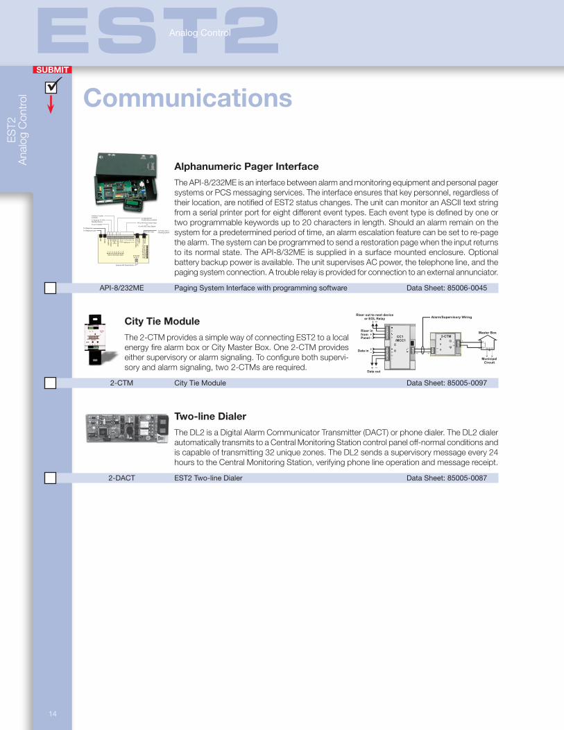
The API-8/232ME is an interface between alarm and monitoring equipment and personal pager systems or PCS messaging services. The interface ensures that key personnel, regardless of their location, are notified of EST2 status changes. The unit can monitor an ASCII text string from a serial printer port for eight different event types. Each event type is defined by one or two programmable keywords up to 20 characters in length. Should an alarm remain on the system for a predetermined period of time, an alarm escalation feature can be set to re-page the alarm. The system can be programmed to send a restoration page when the input returns to its normal state. The API-8/32ME is supplied in a surface mounted enclosure. Optional battery backup power is available. The unit supervises AC power, the telephone line, and the paging system connection. A trouble relay is provided for connection to an external annunciator.
API-8/232ME Paging System Interface with programming software Data Sheet: 85006-0045
City Tie Module Alarm/Supervisory Wiring
Riser out to next deviceor EOL Relay
Riser infromPanel
Data in
Data out
Master Box
MunicipalCircuit
CC1/MCC1
2-CTMThe 2-CTM provides a simple way of connecting EST2 to a local energy fire alarm box or City Master Box. One 2-CTM provides either supervisory or alarm signaling. To configure both supervi-sory and alarm signaling, two 2-CTMs are required.
2-CTM City Tie Module Data Sheet: 85005-0097
Two-line Dialer
The DL2 is a Digital Alarm Communicator Transmitter (DACT) or phone dialer. The DL2 dialer automatically transmits to a Central Monitoring Station control panel off-normal conditions and is capable of transmitting 32 unique zones. The DL2 sends a supervisory message every 24 hours to the Central Monitoring Station, verifying phone line operation and message receipt.
2-DACT EST2 Two-line Dialer Data Sheet: 85005-0087
Communications
SUBMIT
Notification
Appliances
Hazard
ous Lo
cation
Devices
Do
or H
olders &
Relays
Initiating D
evicesE
ST2
Analog C
ontrol
15
EST2Analog Control
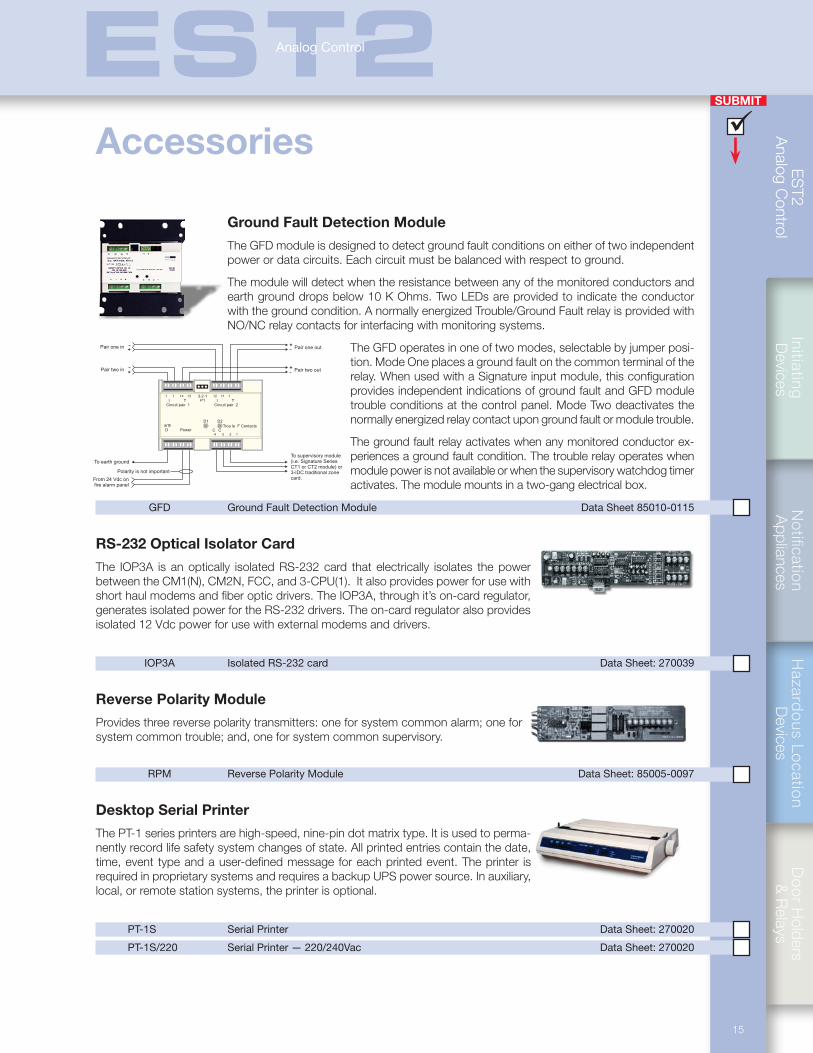
Ground Fault Detection Module
The GFD module is designed to detect ground fault conditions on either of two independent power or data circuits. Each circuit must be balanced with respect to ground.
The module will detect when the resistance between any of the monitored conductors and earth ground drops below 10 K Ohms. Two LEDs are provided to indicate the conductor with the ground condition. A normally energized Trouble/Ground Fault relay is provided with NO/NC relay contacts for interfacing with monitoring systems.
The GFD operates in one of two modes, selectable by jumper posi-tion. Mode One places a ground fault on the common terminal of the relay. When used with a Signature input module, this configuration provides independent indications of ground fault and GFD module trouble conditions at the control panel. Mode Two deactivates the normally energized relay contact upon ground fault or module trouble.
The ground fault relay activates when any monitored conductor ex-periences a ground fault condition. The trouble relay operates when module power is not available or when the supervisory watchdog timer activates. The module mounts in a two-gang electrical box.
GFD Ground Fault Detection Module Data Sheet 85010-0115
RS-232 Optical Isolator Card
The IOP3A is an optically isolated RS-232 card that electrically isolates the power between the CM1(N), CM2N, FCC, and 3-CPU(1). It also provides power for use with short haul modems and fiber optic drivers. The IOP3A, through it’s on-card regulator, generates isolated power for the RS-232 drivers. The on-card regulator also provides isolated 12 Vdc power for use with external modems and drivers.
IOP3A Isolated RS-232 card Data Sheet: 270039
Reverse Polarity Module
Provides three reverse polarity transmitters: one for system common alarm; one for system common trouble; and, one for system common supervisory.
RPM Reverse Polarity Module Data Sheet: 85005-0097
Desktop Serial Printer
The PT-1 series printers are high-speed, nine-pin dot matrix type. It is used to perma-nently record life safety system changes of state. All printed entries contain the date, time, event type and a user-defined message for each printed event. The printer is required in proprietary systems and requires a backup UPS power source. In auxiliary, local, or remote station systems, the printer is optional.
PT-1S Serial Printer Data Sheet: 270020
PT-1S/220 Serial Printer — 220/240Vac Data Sheet: 270020
From 24 Vdc onfire alarm panel
To earth ground
Polarity is not important
Pair one in Pair one out
Pair two in Pair two out
To supervisory module(i.e. Signature SeriesCT1 or CT2 module) or3-IDC traditional zonecard.
++
++
arthD Power
Circuit pair 1 Circuit pair 2I IP1
D1 D2
T3-2-1
T
Trou le F ContactsC C
13
1
1
3
1114
2
11
4
12
Accessories
ES
T2
Ana
log
Con
trol
SUBMIT
16
EST2Analog Control
2-WB Semi-Flush Wallbox Data Sheet: 85005-0099
2-WBD Inner and Outer doors for 2-WB Wallbox Data Sheet: 85005-0099
2-WBS Surface Wallbox Data Sheet: 85005-0099
2-WBDS Inner and Outer doors for 2-WBS Wallbox Data Sheet: 85005-0099
2-WB3 Long Surface Wallbox Data Sheet: 85005-0099
2-WB3D Inner and Outer doors for 2-WB3 Wallbox Data Sheet: 85005-0099
2-WB3D/DF Outer Door for 2-WB3. No viewing window (red finish) Data Sheet: 85005-0099
2-LFK Long Semi-Flush Trim Kit for 2-WB3 Wallbox Data Sheet: 85005-0099
2-WB7 Double wide Surface Wallbox Data Sheet: 85005-0099
2-WB7D Inner and Outer doors for 2-WB7 Wallbox Data Sheet: 85005-0099
2-DFK Double Wide Semi-flush Trim Kit for 2-WB7 Wallbox Data Sheet: 85005-0099
Wallboxes and cabinets
Wallboxes
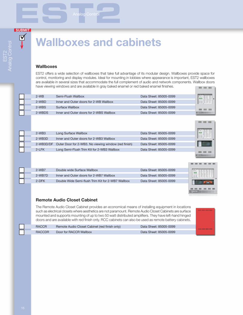
EST2 offers a wide selection of wallboxes that take full advantage of its modular design. Wallboxes provide space for control, monitoring and display modules. Ideal for mounting in lobbies where appearance is important, EST2 wallboxes are available in several sizes that accommodate the full complement of audio and network components. Wallbox doors have viewing windows and are available in gray baked enamel or red baked enamel finishes.
Remote Audio Closet Cabinet
The Remote Audio Closet Cabinet provides an economical means of installing equipment in locations such as electrical closets where aesthetics are not paramount. Remote Audio Closet Cabinets are surface mounted and supports mounting of up to two 50 watt distributed amplifiers. They have left-hand hinged doors and are available with red finish only. RCC cabinets can also be used as remote battery cabinets.
RACCR Remote Audio Closet Cabinet (red finish only) Data Sheet: 85005-0099
RACCDR Door for RACCR Wallbox Data Sheet: 85005-0099
Notification
Appliances
Hazard
ous Lo
cation
Devices
Do
or H
olders &
Relays
Initia
ting
D
evices
17
EST2I n t e l l i g e n t I n i t i a t i n g D e v i c e s
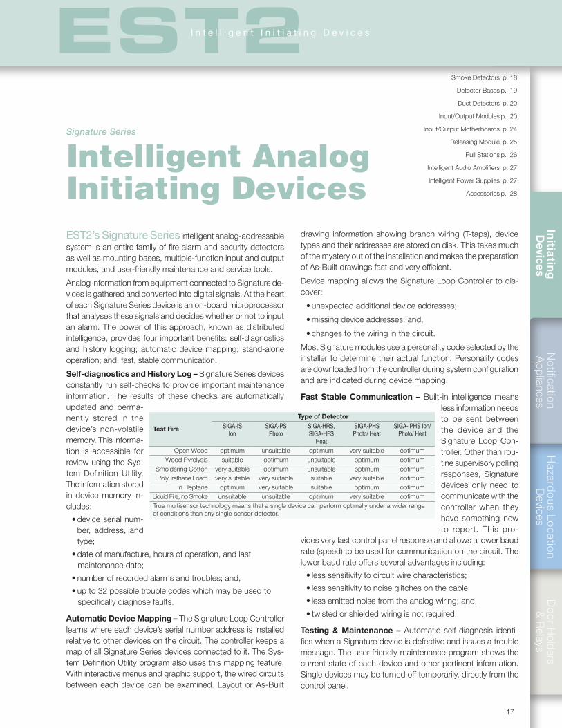
Test Fire
Type of DetectorSIGA-IS
IonSIGA-PS
PhotoSIGA-HRS, SIGA-HFS
Heat
SIGA-PHS Photo/ Heat
SIGA-IPHS Ion/Photo/ Heat
Open Wood optimum unsuitable optimum very suitable optimumWood Pyrolysis suitable optimum unsuitable optimum optimum
Smoldering Cotton very suitable optimum unsuitable optimum optimumPolyurethane Foam very suitable very suitable suitable very suitable optimum
n Heptane optimum very suitable suitable optimum optimumLiquid Fire, no Smoke unsuitable unsuitable optimum very suitable optimumTrue multisensor technology means that a single device can perform optimally under a wider range of conditions than any single-sensor detector.
EST2’s Signature Series intelligent analog-addressable system is an entire family of fire alarm and security detectors as well as mounting bases, multiple-function input and output modules, and user-friendly maintenance and service tools.
Analog information from equipment connected to Signature de-vices is gathered and converted into digital signals. At the heart of each Signature Series device is an on-board microprocessor that analyses these signals and decides whether or not to input an alarm. The power of this approach, known as distributed intelligence, provides four important benefits: self-diagnostics and history logging; automatic device mapping; stand-alone operation; and, fast, stable communication.
Self-diagnostics and History Log – Signature Series devices constantly run self-checks to provide important maintenance information. The results of these checks are automatically updated and perma-nently stored in the device’s non-volatile memory. This informa-tion is accessible for review using the Sys-tem Definition Utility. The information stored in device memory in-cludes:
• device serial num-ber, address, and type;
• date of manufacture, hours of operation, and last maintenance date;
• number of recorded alarms and troubles; and,
• up to 32 possible trouble codes which may be used to specifically diagnose faults.
Automatic Device Mapping – The Signature Loop Controller learns where each device’s serial number address is installed relative to other devices on the circuit. The controller keeps a map of all Signature Series devices connected to it. The Sys-tem Definition Utility program also uses this mapping feature. With interactive menus and graphic support, the wired circuits between each device can be examined. Layout or As-Built
drawing information showing branch wiring (T-taps), device types and their addresses are stored on disk. This takes much of the mystery out of the installation and makes the preparation of As-Built drawings fast and very efficient.
Device mapping allows the Signature Loop Controller to dis-cover:
• unexpected additional device addresses;
• missing device addresses; and,
• changes to the wiring in the circuit.
Most Signature modules use a personality code selected by the installer to determine their actual function. Personality codes are downloaded from the controller during system configuration and are indicated during device mapping.
Fast Stable Communication – Built-in intelligence means less information needs to be sent between the device and the Signature Loop Con-troller. Other than rou-tine supervisory polling responses, Signature devices only need to communicate with the controller when they have something new to report. This pro-
vides very fast control panel response and allows a lower baud rate (speed) to be used for communication on the circuit. The lower baud rate offers several advantages including:
• less sensitivity to circuit wire characteristics;
• less sensitivity to noise glitches on the cable;
• less emitted noise from the analog wiring; and,
• twisted or shielded wiring is not required.
Testing & Maintenance – Automatic self-diagnosis identi-fies when a Signature device is defective and issues a trouble message. The user-friendly maintenance program shows the current state of each device and other pertinent information. Single devices may be turned off temporarily, directly from the control panel.
Smoke Detectors p. 18
Detector Bases p. 19
Duct Detectors p. 20
Input/Output Modules p. 20
Input/Output Motherboards p. 24
Releasing Module p. 25
Pull Stations p. 26
Intelligent Audio Amplifiers p. 27
Intelligent Power Supplies p. 27
Accessories p. 28
Signature Series
Intelligent Analog Initiating Devices
Init
iati
ng
D
evic
es
SUBMIT
ES
T2
Ana
log
Con
trol
18
EST2I n t e l l i g e n t I n i t i a t i n g D e v i c e s
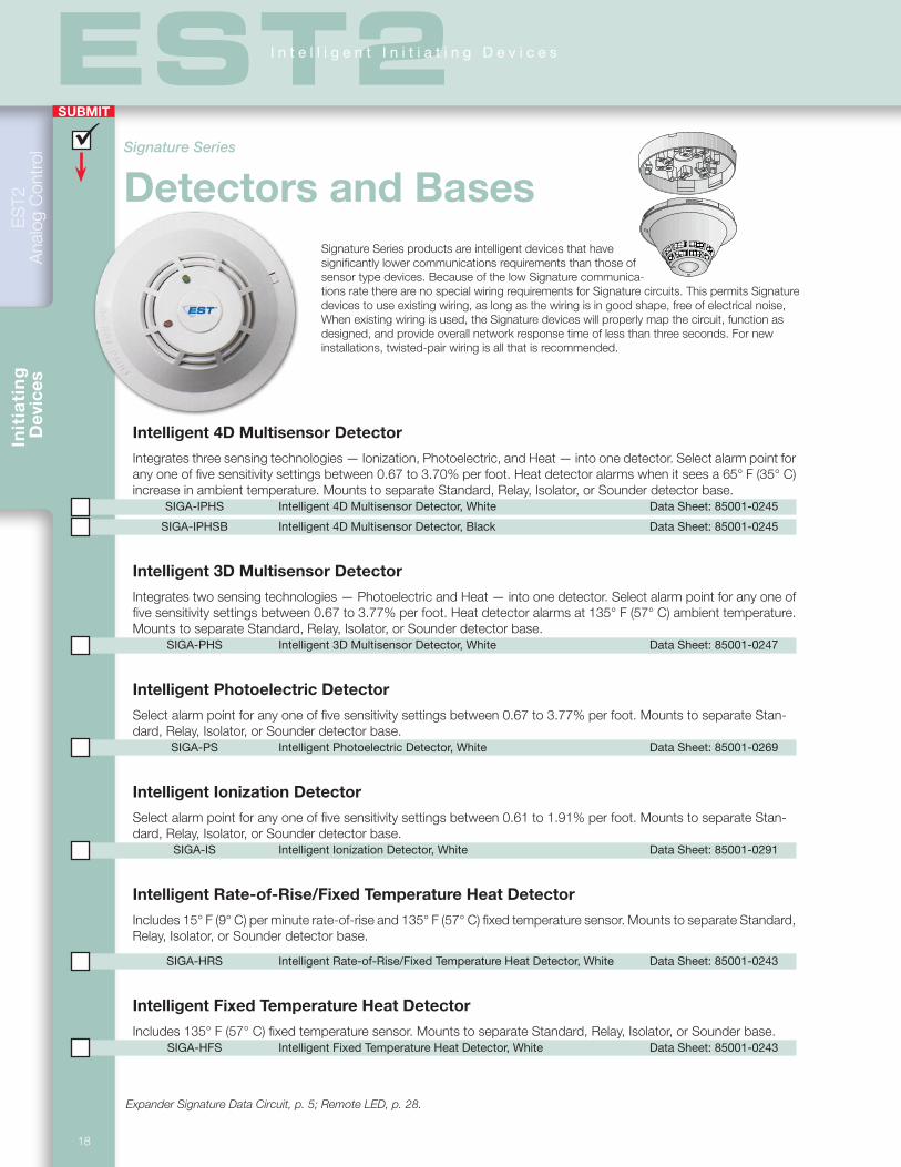
Intelligent 4D Multisensor Detector
Integrates three sensing technologies — Ionization, Photoelectric, and Heat — into one detector. Select alarm point for any one of five sensitivity settings between 0.67 to 3.70% per foot. Heat detector alarms when it sees a 65° F (35° C) increase in ambient temperature. Mounts to separate Standard, Relay, Isolator, or Sounder detector base.
SIGA-IPHS Intelligent 4D Multisensor Detector, White Data Sheet: 85001-0245
SIGA-IPHSB Intelligent 4D Multisensor Detector, Black Data Sheet: 85001-0245
Intelligent 3D Multisensor Detector
Integrates two sensing technologies — Photoelectric and Heat — into one detector. Select alarm point for any one of five sensitivity settings between 0.67 to 3.77% per foot. Heat detector alarms at 135° F (57° C) ambient temperature. Mounts to separate Standard, Relay, Isolator, or Sounder detector base.
SIGA-PHS Intelligent 3D Multisensor Detector, White Data Sheet: 85001-0247
Intelligent Photoelectric Detector
Select alarm point for any one of five sensitivity settings between 0.67 to 3.77% per foot. Mounts to separate Stan-dard, Relay, Isolator, or Sounder detector base.
SIGA-PS Intelligent Photoelectric Detector, White Data Sheet: 85001-0269
Intelligent Ionization Detector
Select alarm point for any one of five sensitivity settings between 0.61 to 1.91% per foot. Mounts to separate Stan-dard, Relay, Isolator, or Sounder detector base.
SIGA-IS Intelligent Ionization Detector, White Data Sheet: 85001-0291
Intelligent Rate-of-Rise/Fixed Temperature Heat Detector
Includes 15° F (9° C) per minute rate-of-rise and 135° F (57° C) fixed temperature sensor. Mounts to separate Standard, Relay, Isolator, or Sounder detector base.
SIGA-HRS Intelligent Rate-of-Rise/Fixed Temperature Heat Detector, White Data Sheet: 85001-0243
Intelligent Fixed Temperature Heat Detector
Includes 135° F (57° C) fixed temperature sensor. Mounts to separate Standard, Relay, Isolator, or Sounder base. SIGA-HFS Intelligent Fixed Temperature Heat Detector, White Data Sheet: 85001-0243
Expander Signature Data Circuit, p. 5; Remote LED, p. 28.
Signature Series
Detectors and BasesSignature Series products are intelligent devices that have significantly lower communications requirements than those of sensor type devices. Because of the low Signature communica-tions rate there are no special wiring requirements for Signature circuits. This permits Signature devices to use existing wiring, as long as the wiring is in good shape, free of electrical noise, When existing wiring is used, the Signature devices will properly map the circuit, function as designed, and provide overall network response time of less than three seconds. For new installations, twisted-pair wiring is all that is recommended.
SUBMIT
Notification
Appliances
Hazard
ous Lo
cation
Devices
Do
or H
olders &
Relays
Initia
ting
D
evices
19
EST2I n t e l l i g e n t I n i t i a t i n g D e v i c e s
SIG+ SIG-
DATA-OUT
DATA-IN
DATA+IN/OUT
+
-
+
-
+
-
+
-
Volume setting
24 Vdc inFrom power supply
or previous base
Data inFrom Signature controller
or previous device
Tone setting
24 Vdc outTo next baseor EOL relay
Data outTo next Signaturedevice
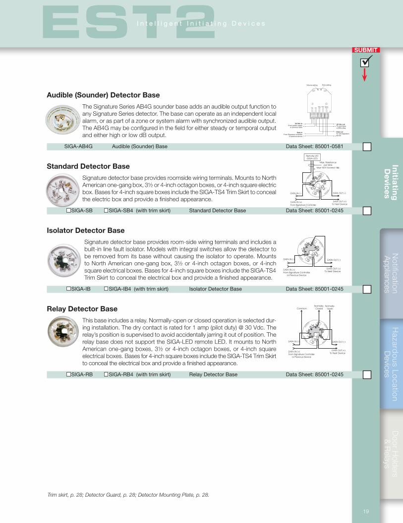
Audible (Sounder) Detector Base
The Signature Series AB4G sounder base adds an audible output function to any Signature Series detector. The base can operate as an independent local alarm, or as part of a zone or system alarm with synchronized audible output. The AB4G may be configured in the field for either steady or temporal output and either high or low dB output.
SIGA-AB4G Audible (Sounder) Base Data Sheet: 85001-0581
Standard Detector Base
Signature detector base provides roomside wiring terminals. Mounts to North American one-gang box, 3½ or 4-inch octagon boxes, or 4-inch square electric box. Bases for 4-inch square boxes include the SIGA-TS4 Trim Skirt to conceal the electric box and provide a finished appearance.
SIGA-SB SIGA-SB4 (with trim skirt) Standard Detector Base Data Sheet: 85001-0245
Isolator Detector Base
Signature detector base provides room-side wiring terminals and includes a built-in line fault isolator. Models with integral switches allow the detector to be removed from its base without causing the isolator to operate. Mounts to North American one-gang box, 3½ or 4-inch octagon boxes, or 4-inch square electrical boxes. Bases for 4-inch square boxes include the SIGA-TS4 Trim Skirt to conceal the electrical box and provide a finished appearance.
SIGA-IB SIGA-IB4 (with trim skirt) Isolator Detector Base Data Sheet: 85001-0245
Relay Detector Base
This base includes a relay. Normally-open or closed operation is selected dur-ing installation. The dry contact is rated for 1 amp (pilot duty) @ 30 Vdc. The relay’s position is supervised to avoid accidentally jarring it out of position. The relay base does not support the SIGA-LED remote LED. It mounts to North American one-gang boxes, 3½ or 4-inch octagon boxes, or 4-inch square electrical boxes. Bases for 4-inch square boxes include the SIGA-TS4 Trim Skirt to conceal the electrical box and provide a finished appearance.
SIGA-RB SIGA-RB4 (with trim skirt) Relay Detector Base Data Sheet: 85001-0245
Trim skirt, p. 28; Detector Guard, p. 28; Detector Mounting Plate, p. 28.
Init
iati
ng
D
evic
es
SUBMIT
ES
T2
Ana
log
Con
trol
20
EST2I n t e l l i g e n t I n i t i a t i n g D e v i c e s
Signature Series intelligent input/output modules feature multiple user-set personality codes that define the module’s behavior.
Signature Series input/output modules are extremely flexible and power-ful devices that gather analog information from the slave devices connected to them and convert this data into digital signals. They are available in models that mount in standard one- or two-gang electrical boxes, as well as versions that plug into UIO motherboards. The actual function of each module is determined by its installer-selected personality code. This is downloaded to the module from the Signature Loop Controller during system configuration. Because they are intelligent devices, all decisions are made at the module. This allows lower communication speed but very fast control panel response time and less sensitivity to line noise and loop wiring properties. As a result, twisted or shielded wire is not required.
Signature Series
Input/Output Modules
Standard two-gang mount
Plug-in UIOs with motherboard
SIGA-SD Intelligent SuperDuct Detector Data Sheet: 85001-0584
Sampling Tubes SD-T8 (8”) SD-T18 (18”) SD-T24 (24”) SD-T36 (36”) SD-T42 (42”) SD-T60 (60”) SD-T78 (78”) SD-T120 (120”)
Remote Test Stations SD-TRM (magnetic) SD-TRK (keyed) SIGA-LED (Remote alarm LED)
Accessories SD-GSK (cover gasket kit) SD-MAG (Test magnet kit) SD-VTK (Air velocity test kit, stoppers only) SIGA-SDPCB (PCB/Signature sensor kit)
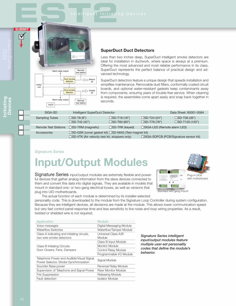
SuperDuct Duct Detectors
Less than two inches deep, SuperDuct intelligent smoke detectors are ideal for installation in ductwork, where space is always at a premium. Offering the most advanced and most reliable performance in its class, SuperDuct represents the perfect balance of practical design and ad-vanced technology.
SuperDuct detectors feature a unique design that speeds installation and simplifies maintenance. Removable dust filters, conformally coated circuit boards, and optional water-resistant gaskets keep contaminants away from components, ensuring years of trouble-free service. When cleaning is required, the assemblies come apart easily and snap back together in seconds.
Returnair
Duct smokedetector
Supplyair
Duct smokedetector
Remotetest station
FACP
HVACunit
Alarm relay output
Alarm relay output
Remotetest station
Application ModuleVoice messages Digital Messaging ModuleWaterflow Switches Waterflow/Tamper ModuleClass A indicating and initiating circuits, two-wire smoke detectors
Universal Class A/B Module
Class B Initiating Circuits: Door Closers, Fans, Dampers
Class B Input Module Monitor ModuleControl Relay ModuleProgrammable I/O Module
Telephone Power and Audible/Visual Signal Power Selector, Strobe Synchronization
Signal Module
Sounder Base power Reversal Relay ModuleSupervision of Telephone and Signal Power Riser Monitor ModuleFire Suppression Releasing ModuleFault detection Isolator Module
SUBMIT
Notification
Appliances
Hazard
ous Lo
cation
Devices
Do
or H
olders &
Relays
Initia
ting
D
evices
21
EST2I n t e l l i g e n t I n i t i a t i n g D e v i c e s
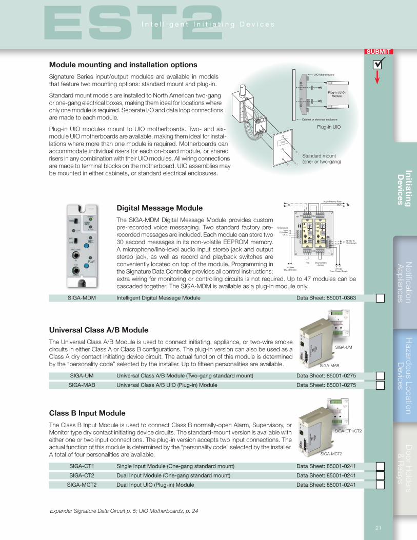
Module mounting and installation options
Signature Series input/output modules are available in models that feature two mounting options: standard mount and plug-in.
Standard mount models are installed to North American two-gang or one-gang electrical boxes, making them ideal for locations where only one module is required. Separate I/O and data loop connections are made to each module.
Plug-in UIO modules mount to UIO motherboards. Two- and six-module UIO motherboards are available, making them ideal for instal-lations where more than one module is required. Motherboards can accommodate individual risers for each on-board module, or shared risers in any combination with their UIO modules. All wiring connections are made to terminal blocks on the motherboard. UIO assemblies may be mounted in either cabinets, or standard electrical enclosures.
Digital Message Module
The SIGA-MDM Digital Message Module provides custom pre-recorded voice messaging. Two standard factory pre-recorded messages are included. Each module can store two 30 second messages in its non-volatile EEPROM memory. A microphone/line-level audio input stereo jack and output stereo jack, as well as record and playback switches are conveniently located on top of the module. Programming in the Signature Data Controller provides all control instructions; extra wiring for monitoring or controlling circuits is not required. Up to 47 modules can be cascaded together. The SIGA-MDM is available as a plug-in module only.
SIGA-MDM Intelligent Digital Message Module Data Sheet: 85001-0363
4321
4321
1 2 3 4
1 2 3 4
1 2 3 4
1 2 3 4
P1 P2
TB1 TB2TB7
TB8 TB9
TB15PLAY
REC.
LINE
IN
HEAD
PHONES
MSG 1
MSG 2
CLIP
MIC.
LINE
SDC
NORMAL
ACTIVE
PLAY
REC.
LINE
IN
HEAD
PHONES
MSG 1
MSG 2
CLIP
MIC.
LINE
SDC
NORMAL
ACTIVE
IN OUT
Audio Preamp Riser
24 Vdc ToOther Loads
24 VdcFrom Power Supply
First DownstreamJumper
To OtherSIGA Devices
To SignatureLoop
Controller(SLC)
_
_
+
+
Expander Signature Data Circuit p. 5; UIO Motherboards, p. 24
Universal Class A/B Module
The Universal Class A/B Module is used to connect initiating, appliance, or two-wire smoke circuits in either Class A or Class B configurations. The plug-in version can also be used as a Class A dry contact initiating device circuit. The actual function of this module is determined by the “personality code” selected by the installer. Up to fifteen personalities are available.
SIGA-UM Universal Class A/B Module (Two-gang standard mount) Data Sheet: 85001-0275
SIGA-MAB Universal Class A/B UIO (Plug-in) Module Data Sheet: 85001-0275
SIGA-UM
Class B Input Module
The Class B Input Module is used to connect Class B normally-open Alarm, Supervisory, or Monitor type dry contact initiating device circuits. The standard-mount version is available with either one or two input connections. The plug-in version accepts two input connections. The actual function of this module is determined by the “personality code” selected by the installer. A total of four personalities are available.
SIGA-CT1 Single Input Module (One-gang standard mount) Data Sheet: 85001-0241
SIGA-CT2 Dual Input Module (One-gang standard mount) Data Sheet: 85001-0241
SIGA-MCT2 Dual Input UIO (Plug-in) Module Data Sheet: 85001-0241
SIGA-CT1/CT2
SIGA-MCT2
SIGA-MAB
Standard mount (one- or two-gang)
FIRE ALARM
MODULE
UIO Motherboard
Plug-in (UIO)Module
Cabinet or electrical enclosure
Plug-in UIO
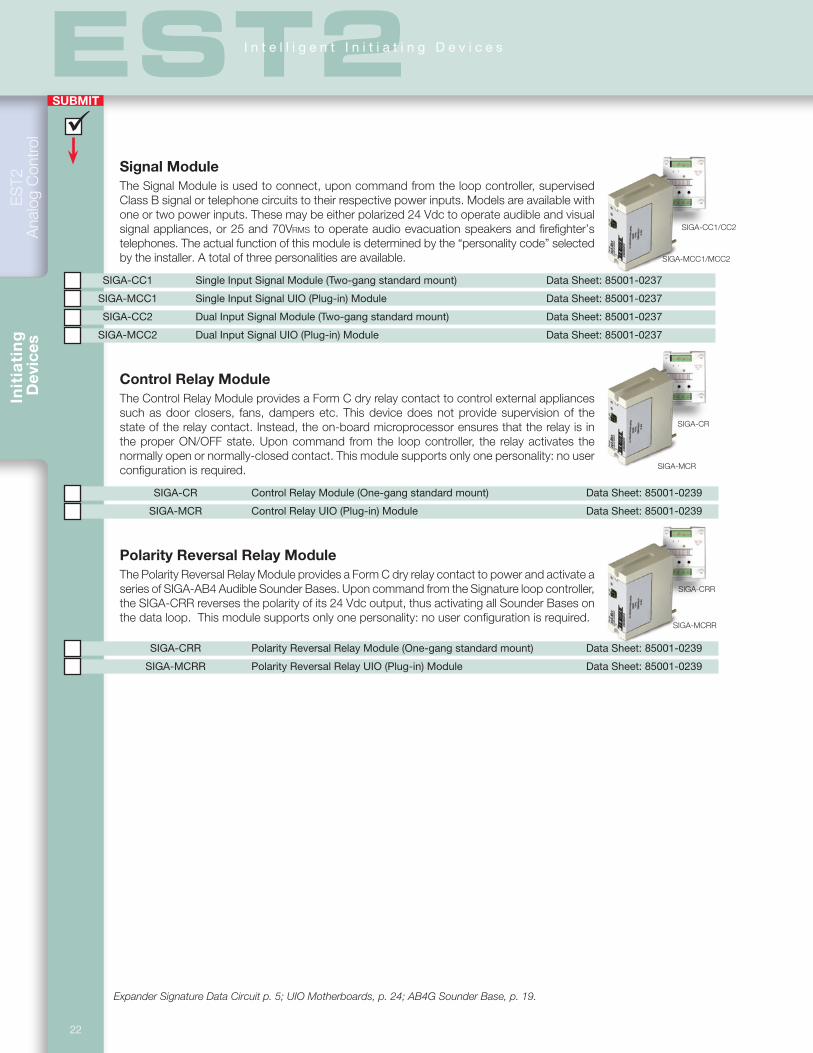
Init
iati
ng
D
evic
es
SUBMIT
ES
T2
Ana
log
Con
trol
22
EST2I n t e l l i g e n t I n i t i a t i n g D e v i c e s
Signal ModuleThe Signal Module is used to connect, upon command from the loop controller, supervised Class B signal or telephone circuits to their respective power inputs. Models are available with one or two power inputs. These may be either polarized 24 Vdc to operate audible and visual signal appliances, or 25 and 70Vrms to operate audio evacuation speakers and firefighter’s telephones. The actual function of this module is determined by the “personality code” selected by the installer. A total of three personalities are available.
SIGA-CC1 Single Input Signal Module (Two-gang standard mount) Data Sheet: 85001-0237
SIGA-MCC1 Single Input Signal UIO (Plug-in) Module Data Sheet: 85001-0237
SIGA-CC2 Dual Input Signal Module (Two-gang standard mount) Data Sheet: 85001-0237
SIGA-MCC2 Dual Input Signal UIO (Plug-in) Module Data Sheet: 85001-0237
Control Relay ModuleThe Control Relay Module provides a Form C dry relay contact to control external appliances such as door closers, fans, dampers etc. This device does not provide supervision of the state of the relay contact. Instead, the on-board microprocessor ensures that the relay is in the proper ON/OFF state. Upon command from the loop controller, the relay activates the normally open or normally-closed contact. This module supports only one personality: no user configuration is required.
SIGA-CR Control Relay Module (One-gang standard mount) Data Sheet: 85001-0239
SIGA-MCR Control Relay UIO (Plug-in) Module Data Sheet: 85001-0239
Polarity Reversal Relay ModuleThe Polarity Reversal Relay Module provides a Form C dry relay contact to power and activate a series of SIGA-AB4 Audible Sounder Bases. Upon command from the Signature loop controller, the SIGA-CRR reverses the polarity of its 24 Vdc output, thus activating all Sounder Bases on the data loop. This module supports only one personality: no user configuration is required.
SIGA-CRR Polarity Reversal Relay Module (One-gang standard mount) Data Sheet: 85001-0239
SIGA-MCRR Polarity Reversal Relay UIO (Plug-in) Module Data Sheet: 85001-0239
Expander Signature Data Circuit p. 5; UIO Motherboards, p. 24; AB4G Sounder Base, p. 19.
SIGA-CC1/CC2
SIGA-MCC1/MCC2
SIGA-CR
SIGA-MCR
SIGA-CRR
SIGA-MCRR
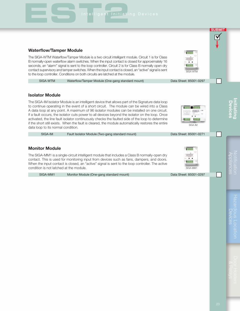
SUBMIT
Notification
Appliances
Hazard
ous Lo
cation
Devices
Do
or H
olders &
Relays
Initia
ting
D
evices
23
EST2I n t e l l i g e n t I n i t i a t i n g D e v i c e s
Waterflow/Tamper Module
The SIGA-WTM Waterflow/Tamper Module is a two circuit intelligent module. Circuit 1 is for Class B normally-open waterflow alarm switches. When the input contact is closed for approximately 16 seconds, an “alarm” signal is sent to the loop controller. Circuit 2 is for Class B normally open dry contact supervisory and tamper switches. When the input contact is closed, an “active” signal is sent to the loop controller. Conditions on both circuits are latched at the module.
SIGA-WTM Waterflow/Tamper Module (One-gang standard mount) Data Sheet: 85001-0297
Isolator Module
The SIGA-IM Isolator Module is an intelligent device that allows part of the Signature data loop to continue operating in the event of a short circuit. The module can be wired into a Class A data loop at any point. A maximum of 96 isolator modules can be installed on one circuit. If a fault occurs, the isolator cuts power to all devices beyond the isolator on the loop. Once activated, the line fault isolator continuously checks the faulted side of the loop to determine if the short still exists. When the fault is cleared, the module automatically restores the entire data loop to its normal condition.
SIGA-IM Fault Isolator Module (Two-gang standard mount) Data Sheet: 85001-0271
Monitor Module
The SIGA-MM1 is a single-circuit intelligent module that includes a Class B normally-open dry contact. This is used for monitoring input from devices such as fans, dampers, and doors. When the input contact is closed, an “active” signal is sent to the loop controller. The active condition is not latched at the module.
SIGA-MM1 Monitor Module (One-gang standard mount) Data Sheet: 85001-0297
SIGA-IM
SIGA-WTM
SIGA-MM1
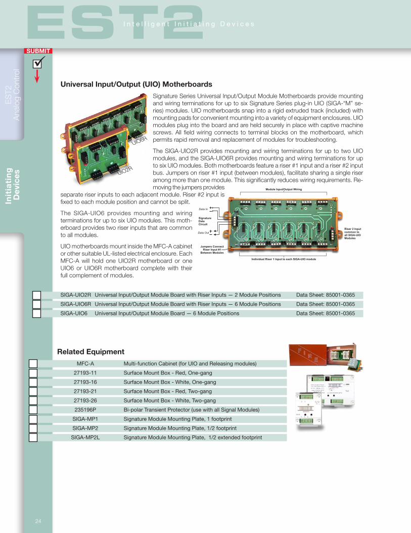
Init
iati
ng
D
evic
es
SUBMIT
ES
T2
Ana
log
Con
trol
24
EST2I n t e l l i g e n t I n i t i a t i n g D e v i c e s
Related Equipment
MFC-A Multi-function Cabinet (for UIO and Releasing modules)
27193-11 Surface Mount Box - Red, One-gang
27193-16 Surface Mount Box - White, One-gang
27193-21 Surface Mount Box - Red, Two-gang
27193-26 Surface Mount Box - White, Two-gang
235196P Bi-polar Transient Protector (use with all Signal Modules)
SIGA-MP1 Signature Module Mounting Plate, 1 footprint
SIGA-MP2 Signature Module Mounting Plate, 1/2 footprint
SIGA-MP2L Signature Module Mounting Plate, 1/2 extended footprint
Riser 2 Input
common to
all SIGA-UIO
Modules
Jumpers Connect
Riser Input #1
Between Modules
Individual Riser 1 Input to each SIGA-UIO module
Module Input/Output Wiring
Signature
Data
Circuit
Data In
Data Out
Universal Input/Output (UIO) Motherboards
Signature Series Universal Input/Output Module Motherboards provide mounting and wiring terminations for up to six Signature Series plug-in UIO (SIGA-“M” se-ries) modules. UIO motherboards snap into a rigid extruded track (included) with mounting pads for convenient mounting into a variety of equipment enclosures. UIO modules plug into the board and are held securely in place with captive machine screws. All field wiring connects to terminal blocks on the motherboard, which permits rapid removal and replacement of modules for troubleshooting.
The SIGA-UIO2R provides mounting and wiring terminations for up to two UIO modules, and the SIGA-UIO6R provides mounting and wiring terminations for up to six UIO modules. Both motherboards feature a riser #1 input and a riser #2 input bus. Jumpers on riser #1 input (between modules), facilitate sharing a single riser among more than one module. This significantly reduces wiring requirements. Re-moving the jumpers provides
separate riser inputs to each adjacent module. Riser #2 input is fixed to each module position and cannot be split.
The SIGA-UIO6 provides mounting and wiring terminations for up to six UIO modules. This moth-erboard provides two riser inputs that are common to all modules.
UIO motherboards mount inside the MFC-A cabinet or other suitable UL-listed electrical enclosure. Each MFC-A will hold one UIO2R motherboard or one UIO6 or UIO6R motherboard complete with their full complement of modules.
SIGA-UIO2R Universal Input/Output Module Board with Riser Inputs — 2 Module Positions Data Sheet: 85001-0365
SIGA-UIO6R Universal Input/Output Module Board with Riser Inputs — 6 Module Positions Data Sheet: 85001-0365
SIGA-UIO6 Universal Input/Output Module Board — 6 Module Positions Data Sheet: 85001-0365
UIO6R
UIO2R

SUBMIT
Notification
Appliances
Hazard
ous Lo
cation
Devices
Do
or H
olders &
Relays
Initia
ting
D
evices
25
EST2I n t e l l i g e n t I n i t i a t i n g D e v i c e s
Releasing Module
The Signature Series Releasing Module (SIGA-REL) is an analog addressable module that works with fire suppression systems designed to release extinguish-ing gas such as Halon. Its primary function is the control of sprinkler pre-action routines and the initiation of suppression system deluge functions. The module is easily configured in the field and offers a wide range of options that prevent the unnecessary release of extinguishing agent.
The SIGA-REL is a network component consisting of:• Two supervised release circuits• Two supervised pre-release circuits• One supervised manual
release input circuit• One supervised abort cir-
cuit for N/O abort switch• One first alarm output
relay (Form C Contact)
The releasing module includes a built-in timer that inhibits the deluge function during the pre-action routine. One of four pre-action routines, may be selected by means of dip-switches on the module. The duration of automatic and manual time delays, as well as the abort time settings are also selectable with dip-switches. The SIGA-REL mounts inside an MFC-A cabinet or other suitable UL-listed electrical enclosure. Each MFC-A will hold one SIGA-REL.
Available releasing module accessories include dedicated pull sta-tions, abort switches and service switches. Together with the SIGA-REL, they comprise a complete fire suppression package.
SIGA-REL Analog addressable releasing module Data Sheet: 85001-0531
RELA-ABT Abort station Data Sheet: 85001-0531
RELA-SRV Service disconnect station Data Sheet: 85001-0531
276A-REL Manual releasing station (single-action) Data Sheet: 85001-0531
278A-REL Manual releasing station (double-action) Data Sheet: 85001-0531
RELA-EOL Polarized end-of-line relay Data Sheet: 85001-0531
Abort
Manual Release
TB3 TB2
TB6
TB4 TB5
TB1
SW1-SW8
First alarm outputForm C 3 A @24 Vdc
Signature data in
Signature data out
+_
+_
Release CCT1
+
_24 Vdc in
24 Vdc out
Pre-release CCT2 (steady)
Pre-release CCT1 (pulsed 15/60)
SIGA-REL
+
_
1
2
3
4
RELA-EOL
1
2
3
4
RELA-EOL
Release CCT2
+_
+_
+_
+_
DS1
DS2
DS4DS3DS5
DS6 DS7
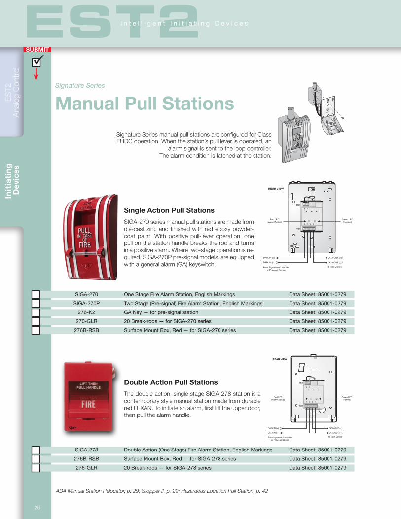
Init
iati
ng
D
evic
es
SUBMIT
ES
T2
Ana
log
Con
trol
26
EST2I n t e l l i g e n t I n i t i a t i n g D e v i c e s
LIFT
NORMAL
8
4
7
3 2 1
DATA OUT (+)DATA IN (+)
DATA OUT (-)DATA IN (-)
To Next DeviceFrom Signature Controlleror Previous Device
Green LED(Normal)
Red LED(Alarm/Active)
REAR VIEW
TB1
TB2
8
4
7
3 2 1
DATA OUT (+)DATA IN (+)
DATA OUT (-)DATA IN (-)
To Next DeviceFrom Signature Controlleror Previous Device
Green LED(Normal)
Red LED(Alarm/Active)
REAR VIEW
TB1
TB2
Signature Series manual pull stations are configured for Class B IDC operation. When the station’s pull lever is operated, an
alarm signal is sent to the loop controller. The alarm condition is latched at the station.
ADA Manual Station Relocator, p. 29; Stopper II, p. 29; Hazardous Location Pull Station, p. 42
Single Action Pull Stations
SIGA-270 series manual pull stations are made from die-cast zinc and finished with red epoxy powder-coat paint. With positive pull-lever operation, one pull on the station handle breaks the rod and turns in a positive alarm. Where two-stage operation is re-quired, SIGA-270P pre-signal models are equipped with a general alarm (GA) keyswitch.
SIGA-270 One Stage Fire Alarm Station, English Markings Data Sheet: 85001-0279
SIGA-270P Two Stage (Pre-signal) Fire Alarm Station, English Markings Data Sheet: 85001-0279
276-K2 GA Key — for pre-signal station Data Sheet: 85001-0279
270-GLR 20 Break-rods — for SIGA-270 series Data Sheet: 85001-0279
276B-RSB Surface Mount Box, Red — for SIGA-270 series Data Sheet: 85001-0279
Double Action Pull Stations
The double action, single stage SIGA-278 station is a contemporary style manual station made from durable red LEXAN. To initiate an alarm, first lift the upper door, then pull the alarm handle.
SIGA-278 Double Action (One Stage) Fire Alarm Station, English Markings Data Sheet: 85001-0279
276B-RSB Surface Mount Box, Red — for SIGA-278 series Data Sheet: 85001-0279
276-GLR 20 Break-rods — for SIGA-278 series Data Sheet: 85001-0279
Signature Series
Manual Pull Stations
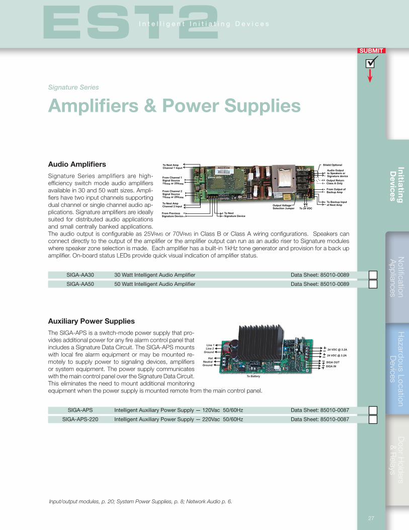
SUBMIT
Notification
Appliances
Hazard
ous Lo
cation
Devices
Do
or H
olders &
Relays
Initia
ting
D
evices
27
EST2I n t e l l i g e n t I n i t i a t i n g D e v i c e s
To Battery
Ground
Neutral
Hot
Line 1
Line 2
Ground
24 VDC @ 3.2A
24 VDC @ 3.2A
SIGA OUT
SIGA IN
To 24 VDC
From Output of
Backup Amp
To Backup Input
of Next Amp
Shield Optional
Output Return
Class A Only
Audio Output
to Speakers or
Signature device
Output Voltage
Selection Jumper
To Next
Signature Device
From Previous
Signature Device
From Channel 1
Signal Source
1Vrms or 25Vrms
To Next Amp
Channel 1 Input
To Next Amp
Channel 2 Input
From Channel 2
Signal Source
1Vrms or 25Vrms
Status LEDs
Status LEDs
Audio Amplifiers
Signature Series amplifiers are high-efficiency switch mode audio amplifiers available in 30 and 50 watt sizes. Ampli-fiers have two input channels supporting dual channel or single channel audio ap-plications. Signature amplifiers are ideally suited for distributed audio applications and small centrally banked applications. The audio output is configurable as 25Vrms or 70Vrms in Class B or Class A wiring configurations. Speakers can connect directly to the output of the amplifier or the amplifier output can run as an audio riser to Signature modules where speaker zone selection is made. Each amplifier has a built-in 1kHz tone generator and provision for a back up amplifier. On-board status LEDs provide quick visual indication of amplifier status.
SIGA-AA30 30 Watt Intelligent Audio Amplifier Data Sheet: 85010-0089
SIGA-AA50 50 Watt Intelligent Audio Amplifier Data Sheet: 85010-0089
Auxiliary Power Supplies
The SIGA-APS is a switch-mode power supply that pro-vides additional power for any fire alarm control panel that includes a Signature Data Circuit. The SIGA-APS mounts with local fire alarm equipment or may be mounted re-motely to supply power to signaling devices, amplifiers or system equipment. The power supply communicates with the main control panel over the Signature Data Circuit. This eliminates the need to mount additional monitoring equipment when the power supply is mounted remote from the main control panel.
SIGA-APS Intelligent Auxiliary Power Supply — 120Vac 50/60Hz Data Sheet: 85010-0087
SIGA-APS-220 Intelligent Auxiliary Power Supply — 220Vac 50/60Hz Data Sheet: 85010-0087
Input/output modules, p. 20; System Power Supplies, p. 8; Network Audio p. 6.
Signature Series
Amplifiers & Power Supplies
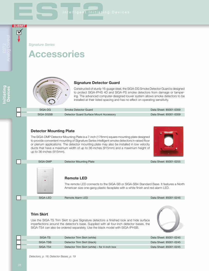
Init
iati
ng
D
evic
es
SUBMIT
ES
T2
Ana
log
Con
trol
28
EST2I n t e l l i g e n t I n i t i a t i n g D e v i c e s
Signature Detector Guard
Constructed of sturdy 16-guage steel, the SIGA-DG Smoke Detector Guard is designed to protect SIGA-IPHS 4D and SIGA-PS smoke detectors from damage or tamper-ing. The advanced computer-designed louver system allows smoke detectors to be installed at their listed spacing and has no effect on operating sensitivity.
SIGA-DG Smoke Detector Guard Data Sheet: 85001-0359
SIGA-DGSB Detector Guard Surface Mount Accessory Data Sheet: 85001-0359
Detector Mounting Plate
The SIGA-DMP Detector Mounting Plate is a 7-inch (178mm) square mounting plate designed to provide convenient mounting of Signature Series intelligent smoke detectors in raised floor or plenum applications. The detector mounting plate may also be installed in low velocity ducts that have a maximum width of up to 36-inches (915mm) and a maximum height of up to 36-inches (915mm).
SIGA-DMP Detector Mounting Plate Data Sheet: 85001-0255
Remote LED
The remote LED connects to the SIGA-SB or SIGA-SB4 Standard Base. It features a North American size one-gang plastic faceplate with a white finish and red alarm LED.
SIGA-LED Remote Alarm LED Data Sheet: 85001-0245
Trim Skirt
Use the SIGA-TS Trim Skirt to give Signature detectors a finished look and hide surface imperfections around the detector’s base. Supplied with all four-inch detector bases, the SIGA-TS4 can also be ordered separately. Use the black model with SIGA-IPHSB.
SIGA-TS Detector Trim Skirt (white) Data Sheet: 85001-0245
SIGA-TSB Detector Trim Skirt (black) Data Sheet: 85001-0245
SIGA-TS4 Detector Trim Skirt (white) – for 4-inch box Data Sheet: 85001-0245
Detectors, p. 18; Detector Bases, p. 19
Signature Series
Accessories
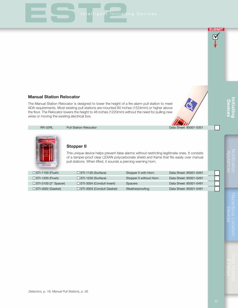
SUBMIT
Notification
Appliances
Hazard
ous Lo
cation
Devices
Do
or H
olders &
Relays
Initia
ting
D
evices
29
EST2I n t e l l i g e n t I n i t i a t i n g D e v i c e s
Manual Station Relocator
The Manual Station Relocator is designed to lower the height of a fire alarm pull station to meet ADA requirements. Most existing pull stations are mounted 60 inches (1524mm) or higher above the floor. The Relocator lowers the height to 48 inches (1220mm) without the need for pulling new wires or moving the existing electrical box.
RR-32RL Pull Station Relocator Data Sheet: 85001-0351
Stopper II
This unique device helps prevent false alarms without restricting legitimate ones. It consists of a tamper-proof clear LEXAN polycarbonate shield and frame that fits easily over manual pull stations. When lifted, it sounds a piercing warning horn.
STI-1100 (Flush) STI-1130 (Surface) Stopper II with Horn Data Sheet: 85001-0491
STI-1200 (Flush) STI-1230 (Surface) Stopper II without Horn Data Sheet: 85001-0491
STI-3100 (2" Spacer) STI-3004 (Conduit Insert) Spacers Data Sheet: 85001-0491
STI-3002 (Gasket) STI-3003 (Conduit Gasket) Weatherproofing Data Sheet: 85001-0491
Detectors, p. 18; Manual Pull Stations, p. 26

Init
iati
ng
D
evic
es
SUBMIT
ES
T2
Ana
log
Con
trol
30
EST2I n t e l l i g e n t I n i t i a t i n g D e v i c e s
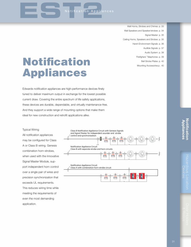
Hazard
ous Lo
cation
Devices
Do
or H
olders &
Relays
31
No
tific
atio
n A
pp
liances
Wall Horns, Strobes and Chimes p. 33
Wall Speakers and Speaker/strobes p. 34
Signal Master p. 35
Ceiling Horns, Speakers and Strobes p. 35
Harsh Environment Signals p. 36
Audible Signals p. 37
Audio System p. 38
Firefighers’ Telephones p. 39
Bell Strobe Plates p. 40
Mounting Accessories p. 40
EST2N o t i fi c a t i o n A p p l i a n c e s
Class B Notification Appliance Circuit with Genesis Signalsand Signal Master for independent sounder and strobecontrol and synchronisation
Notification Appliance CircuitClass B with separate strobe and horn circuits
Notification Appliance CircuitClass A with combination horn-strobe circuit
Notification AppliancesEdwards notification appliances are high-performance devices finely
tuned to deliver maximum output in exchange for the lowest possible
current draw. Covering the entire spectrum of life safety applications,
these devices are durable, dependable, and virtually maintenance-free.
And they support a wide range of mounting options that make them
ideal for new construction and retrofit applications alike.
Typical Wiring
All notification appliances
may be configured for Class
A or Class B wiring. Genesis
combination horn-strobes,
when used with the innovative
Signal Master Module, sup-
port independent horn control
over a single pair of wires and
precision synchronization that
exceeds UL requirements.
This reduces wiring time while
meeting the requirements of
even the most demanding
application.
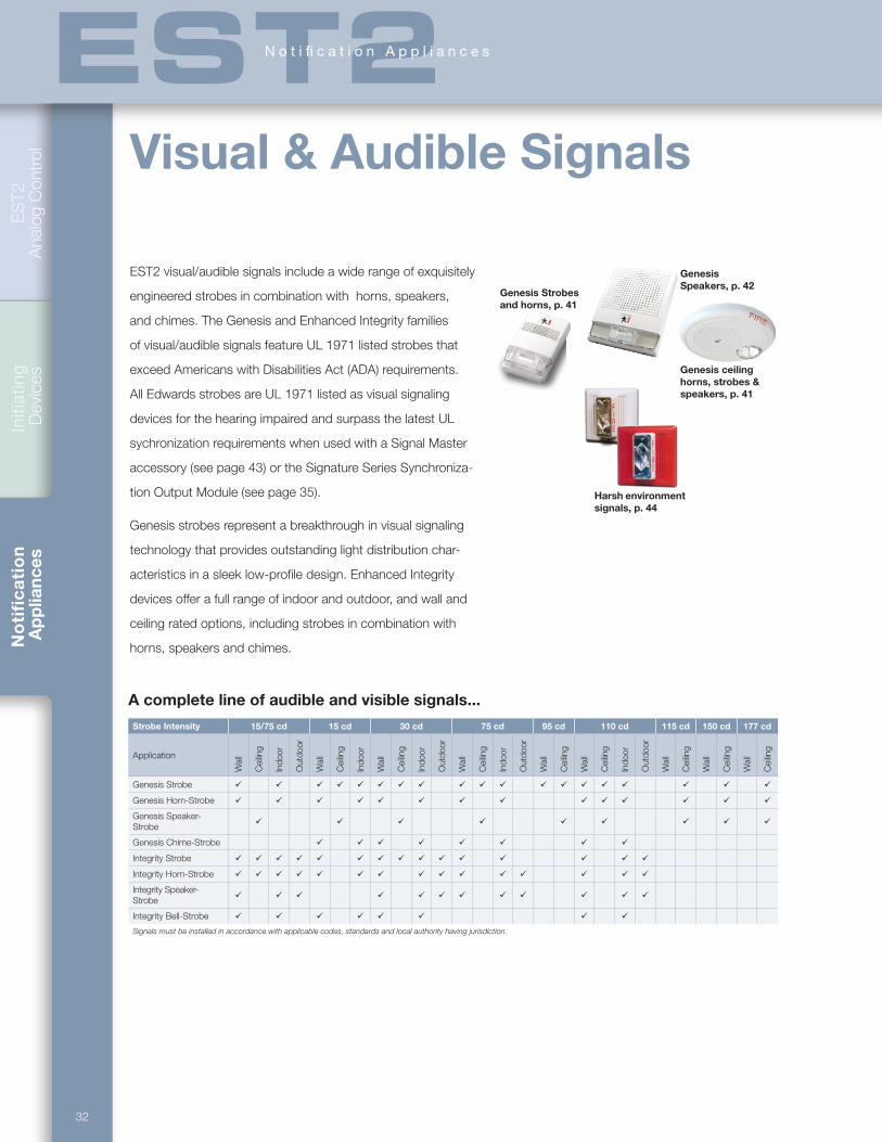
32
ES
T2
Ana
log
Con
trol
Initi
atin
g D
evic
esN
oti
fic
ati
on
Ap
plia
nces
Visual & Audible Signals
EST2 visual/audible signals include a wide range of exquisitely
engineered strobes in combination with horns, speakers,
and chimes. The Genesis and Enhanced Integrity families
of visual/audible signals feature UL 1971 listed strobes that
exceed Americans with Disabilities Act (ADA) requirements.
All Edwards strobes are UL 1971 listed as visual signaling
devices for the hearing impaired and surpass the latest UL
sychronization requirements when used with a Signal Master
accessory (see page 43) or the Signature Series Synchroniza-
tion Output Module (see page 35).
Genesis strobes represent a breakthrough in visual signaling
technology that provides outstanding light distribution char-
acteristics in a sleek low-profile design. Enhanced Integrity
devices offer a full range of indoor and outdoor, and wall and
ceiling rated options, including strobes in combination with
horns, speakers and chimes.
Genesis Strobes and horns, p. 41
Harsh environment signals, p. 44
Genesis ceiling horns, strobes & speakers, p. 41
Genesis Speakers, p. 42
A complete line of audible and visible signals...
Strobe Intensity 15/75 cd 15 cd 30 cd 75 cd 95 cd 110 cd 115 cd 150 cd 177 cd
Application
Wal
l
Cei
ling
Indo
or
Out
door
Wal
l
Cei
ling
Indo
or
Wal
l
Cei
ling
Indo
or
Out
door
Wal
l
Cei
ling
Indo
or
Out
door
Wal
l
Cei
ling
Wal
l
Cei
ling
Indo
or
Out
door
Wal
l
Cei
ling
Wal
l
Cei
ling
Wal
l
Cei
ling
Genesis Strobe ü ü ü ü ü ü ü ü ü ü ü ü ü ü ü ü ü ü ü
Genesis Horn-Strobe ü ü ü ü ü ü ü ü ü ü ü ü ü ü
Genesis Speaker-Strobe ü ü ü ü ü ü ü ü ü
Genesis Chime-Strobe ü ü ü ü ü ü ü ü
Integrity Strobe ü ü ü ü ü ü ü ü ü ü ü ü ü ü ü
Integrity Horn-Strobe ü ü ü ü ü ü ü ü ü ü ü ü ü ü ü
Integrity Speaker-Strobe ü ü ü ü ü ü ü ü ü ü ü ü
Integrity Bell-Strobe ü ü ü ü ü ü ü ü
Signals must be installed in accordance with applicable codes, standards and local authority having jurisdiction.
EST2N o t i fi c a t i o n A p p l i a n c e s
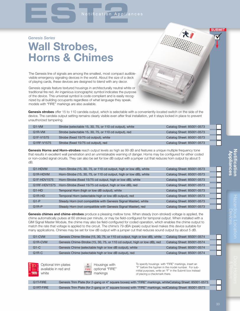
Hazard
ous Lo
cation
Devices
Do
or H
olders &
Relays
33
No
tific
atio
n A
pp
liances
SUBMIT
ü
Genesis Series
Wall Strobes, Horns & Chimes
Genesis strobes offer 15 to 110 candela output, which is selectable with a conveniently-located switch on the side of the device. The candela output setting remains clearly visible even after final installation, yet it stays locked in place to prevent unauthorized tampering.
G1-VM Strobe (selectable 15, 30, 75, or 110 cd output), white Catalog Sheet: 85001-0573
G1R-VM Strobe (selectable 15, 30, 75, or 110 cd output), red Catalog Sheet: 85001-0573
G1F-V1575 Strobe (fixed 15/75 cd output), white Catalog Sheet: 85001-0573
G1RF-V1575 Strobe (fixed 15/75 cd output), red Catalog Sheet: 85001-0573
Genesis Horns and Horn-strobes reach output levels as high as 99 dB and features a unique multiple frequency tone that results in excellent wall penetration and an unmistakable warning of danger. Horns may be configured for either coded or non-coded signal circuits. They can also be set for low dB output with a jumper cut that reduces horn output by about 5 dB.
G1-HDVM Horn-Strobe (15, 30, 75, or 110 cd output, high or low dB), white Catalog Sheet: 85001-0573
G1R-HDVM Horn-Strobe (15, 30, 75, or 110 cd output, high or low dB), white Catalog Sheet: 85001-0573
G1F-HDV1575 Horn-Strobe (fixed 15/75 cd output, high or low dB), white Catalog Sheet: 85001-0573
G1RF-HDV1575 Horn-Strobe (fixed 15/75 cd output, high or low dB), red Catalog Sheet: 85001-0573
G1-HD Temporal Horn (high or low dB output), white Catalog Sheet: 85001-0573
G1R-HD Temporal Horn (selectable high or low dB output), red Catalog Sheet: 85001-0573
G1-P Steady Horn (not compatible with Genesis Signal Master), white Catalog Sheet: 85001-0573
G1R-P Steady Horn (not compatible with Genesis Signal Master), red Catalog Sheet: 85001-0573
Genesis chimes and chime-strobes produce a pleasing mellow tone. When steady (non-stroked) voltage is applied, the chime automatically pulses at 60 strokes per minute, or may be field-configured for temporal output. When installed with a GIM Signal Master Module, the chime may also be field-configured for coded operation, which enables the chime output to match the rate that voltage is applied to the circuit. The chime’s 79 dBA (peak) output level makes this device suitable for many applications. Chimes may be set for low dB output with a jumper cut that reduces sound output by about 5 dB.
G1-CVM Genesis Chime-Strobe (15, 30, 75, or 110 cd output, high or low dB), white Catalog Sheet: 85001-0574
G1R-CVM Genesis Chime-Strobe (15, 30, 75, or 110 cd output, high or low dB), red Catalog Sheet: 85001-0574
G1-C Genesis Chime (selectable high or low dB output), white Catalog Sheet: 85001-0574
G1R-C Genesis Chime (selectable high or low dB output), red Catalog Sheet: 85001-0574
Housings with optional “FIRE” markings
Optional trim plates available in red and white
To specify housings with “FIRE” markings, insert an “F” before the hyphen in the model number. For sub-mittal purposes, write an “F” in the Submit box instead of placing a checkmark there.
G1T-FIRE Genesis Trim Plate (for 2-gang or 4” square boxes) with “FIRE” markings, white Catalog Sheet: 85001-0573
G1RT-FIRE Genesis Trim Plate (for 2-gang or 4” square boxes) with “FIRE” markings, red Catalog Sheet: 85001-0573
The Genesis line of signals are among the smallest, most compact audible-visible emergency signaling devices in the world. About the size of a deck of playing cards, these devices are designed to blend with any decor.
Genesis signals feature textured housings in architecturally neutral white or traditional fire red. An ingenious iconographic symbol indicates the purpose of the device. This universal symbol is code-compliant and is easily recog-nized by all building occupants regardless of what language they speak. models with “FIRE” markings are also available.
EST2N o t i fi c a t i o n A p p l i a n c e s
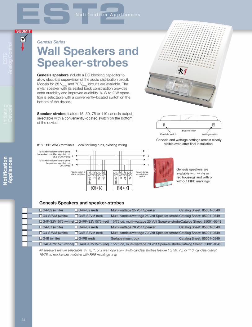
34
ES
T2
Ana
log
Con
trol
Initi
atin
g D
evic
esN
oti
fic
ati
on
Ap
plia
nces
SUBMIT
ü
EST2N o t i fi c a t i o n A p p l i a n c e s
Genesis speakers include a DC blocking capacitor to allow electrical supervision of the audio distribution circuit. Models for 25 VRMS and 70 VRMS circuits are available. The mylar speaker with its sealed back construction provides extra durability and improved audibility. ¼ W to 2 W opera-tion is selectable with a conveniently-located switch on the bottom of the device.
Speaker-strobes feature 15, 30, 75 or 110 candela output, selectable with a conveniently-located switch on the bottom of the device.
Genesis Speakers and speaker-strobes
G4-S2 (white) G4R-S2 (red) Multi-wattage 25 Volt Speaker Catalog Sheet: 85001-0549
G4-S2VM (white) G4R-S2VM (red) Multi-candela/wattage 25 Volt Speaker-strobe Catalog Sheet: 85001-0549
G4F-S2V1575 (white) G4RF-S2V1575 (red) 15/75 cd, multi-wattage 25 Volt Speaker-strobe Catalog Sheet: 85001-0549
G4-S7 (white) G4R-S7 (red) Multi-wattage 70 Volt Speaker Catalog Sheet: 85001-0549
G4-S7VM (white) G4R-S7VM (red) Multi-candela/wattage 70 Volt Speaker-strobe Catalog Sheet: 85001-0549
G4B (white) G4RB (red) Surface mount box Catalog Sheet: 85001-0549
G4F-S7V1575 (white) G4RF-S7V1575 (red) 15/75 cd, multi-wattage 70 Volt Speaker-strobe Catalog Sheet: 85001-0549
All speakers feature selectable ¼, ½, 1, or 2 watt operation. Multi-candela strobes feature 15, 30, 75, or 110 candela output.15/75 cd models are available with FIRE markings only.
#18 - #12 AWG terminals – ideal for long runs, existing wiring
Genesis speakers are available with white or red housings and with or without FIRE markings.
1
Bottom View
Wattage switch
15
Candela switch
To change strobe to temporal(private mode) cut JP1
JP1
Use the Candela Switch and theWattage switch to set desired operation.
Candela and wattage settings remain clearly visible even after final installation.
Genesis Series
Wall Speakers and Speaker-strobes
SP
KR
S+
C S-
Polarity shown inalarm condition
To next deviceor end of line
device
++
SP
KR
S+
C S-
S S
+ +
To listed fire alarm control panel(supervised signal circuit
– 20-24 Vdc)
To listed fire alarm control panel(supervised amplifier signal circuit
– 25.2 or 70.7V rms)
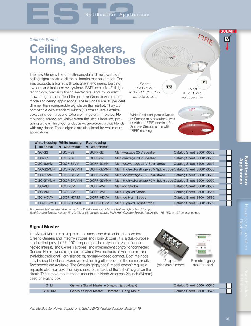
Hazard
ous Lo
cation
Devices
Do
or H
olders &
Relays
35
No
tific
atio
n A
pp
liances
SUBMIT
ü
EST2N o t i fi c a t i o n A p p l i a n c e s
Select ¼, ½, 1, or 2
watt operation!
The new Genesis line of multi-candela and multi-wattage ceiling signals feature all the hallmarks that have made Gen-esis products a big hit with designers, engineers, building owners, and installers everywhere. EST’s exclusive FullLight technology, precision timing electronics, and low current draw bring the benefits of the popular Genesis wall-mount models to ceiling applications. These signals are 30 per cent slimmer than comparable signals on the market. They are compatible with standard 4-inch (10 cm) square electrical boxes and don’t require extension rings or trim plates. No mounting screws are visible when the unit is installed, pro-viding a clean, finished, unobtrusive appearance that blends with any decor. These signals are also listed for wall mount applications.
White housing White housing Red housing no “FIRE” with “FIRE” with “FIRE”
GC-S2 GCF-S2 GCFR-S2 Multi-wattage 25 V Speaker Catalog Sheet: 85001-0558
GC-S7 GCF-S7 GCFR-S7 Multi-wattage 70 V Speaker Catalog Sheet: 85001-0558
GC-S2VM GCF-S2VM GCFR-S2VM Multi-cd/wattage 25 V Spkr-strobe Catalog Sheet: 85001-0556
GC-S2VMH GCF-S2VMH GCFR-S2VMH Multi High-cd/wattage 25 V Spkr-strobe Catalog Sheet: 85001-0556
GC-S7VM GCF-S7VM GCFR-S7VM Multi-cd/wattage 70 V Spkr-strobe Catalog Sheet: 85001-0556
GC-S7VMH GCF-S7VMH GCFR-S7VMH Multi High-cd/wattage 70 V Spkr-strobe Catalog Sheet: 85001-0556
GC-VM GCF-VM GCFR-VM Multi-cd Strobe Catalog Sheet: 85001-0557
GC-VMH GCF-VMH GCFR-VMH Multi High-cd Strobe Catalog Sheet: 85001-0557
GC-HDVM GCF-HDVM GCFR-HDVM Multi-cd Horn-Strobe Catalog Sheet: 85001-0559
GC-HDVMH GCF-HDVMH GCFR-HDVMH Multi High-cd Horn-Strobe Catalog Sheet: 85001-0559
All speakers feature selectable ¼, ½, 1, or 2 watt operation. All horns feature high or low dB output. Multi-Candela Strobes feature 15, 30, 75, or 95 candela output. Multi High-Candela Strobes feature 95, 115, 150, or 177 candela output.
Select 15/30/75/95
and 95/115/150/177 candela output!
Genesis Series
Ceiling Speakers, Horns, and Strobes
Signal Master
The Signal Master is a simple-to-use accessory that adds enhanced fea-tures to Genesis and Integrity strobes and Horn-Strobes. It is a dual-purpose module that provides UL 1971 required precision synchronization for con-nected Integrity and Genesis strobes, and independent control for connected Genesis Horns over a single pair of wires. Two methods of Horn control are available: traditional Horn silence; or, normally-closed contact. Both methods may be used to silence Horns without turning off strobes on the same circuit. Two models are available. The Genesis “piggyback” model doesn’t require a separate electrical box. It simply snaps to the back of the first G1 signal on the circuit. The remote mount model mounts in a North American 2½ inch (64 mm) deep one-gang box.
G1M Genesis Signal Master – Snap-on (piggyback) Catalog Sheet: 85001-0545
G1M-RM Genesis Signal Master – Remote 1-Gang Mount Catalog Sheet: 85001-0545
Snap-on (piggyback) model
Remote 1-gang mount model
Remote Booster Power Supply, p. 8; SIGA-AB4G Audible Sounder Base, p. 19.
White Field configurable Speak-er-Strobes may be ordered with or without “FIRE” marking. Red Speaker-Strobes come with “FIRE” marking.
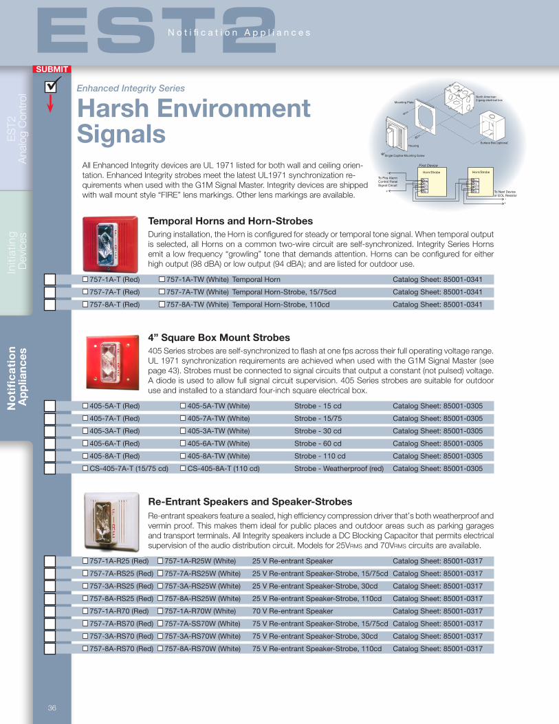
36
ES
T2
Ana
log
Con
trol
Initi
atin
g D
evic
esN
oti
fic
ati
on
Ap
plia
nces
SUBMIT
ü
EST2N o t i fi c a t i o n A p p l i a n c e s
HousingSurface Box (optional)
North American2-gang electrical box
Mounting Plate
Single Captive Mounting Screw
H+H-S+S-
Horn/Strobe
H+H-S+S- To Next Device
or EOL Resistor
To Fire AlarmControl PanelSignal Circuit
+
+
First Device
-
-
Horn/Strobe
Temporal Horns and Horn-Strobes During installation, the Horn is configured for steady or temporal tone signal. When temporal output is selected, all Horns on a common two-wire circuit are self-synchronized. Integrity Series Horns emit a low frequency “growling” tone that demands attention. Horns can be configured for either high output (98 dBA) or low output (94 dBA); and are listed for outdoor use.
757-1A-T (Red) 757-1A-TW (White) Temporal Horn Catalog Sheet: 85001-0341
757-7A-T (Red) 757-7A-TW (White) Temporal Horn-Strobe, 15/75cd Catalog Sheet: 85001-0341
757-8A-T (Red) 757-8A-TW (White) Temporal Horn-Strobe, 110cd Catalog Sheet: 85001-0341
4” Square Box Mount Strobes405 Series strobes are self-synchronized to flash at one fps across their full operating voltage range. UL 1971 synchronization requirements are achieved when used with the G1M Signal Master (see page 43). Strobes must be connected to signal circuits that output a constant (not pulsed) voltage. A diode is used to allow full signal circuit supervision. 405 Series strobes are suitable for outdoor use and installed to a standard four-inch square electrical box.
405-5A-T (Red) 405-5A-TW (White) Strobe - 15 cd Catalog Sheet: 85001-0305
405-7A-T (Red) 405-7A-TW (White) Strobe - 15/75 Catalog Sheet: 85001-0305
405-3A-T (Red) 405-3A-TW (White) Strobe - 30 cd Catalog Sheet: 85001-0305
405-6A-T (Red) 405-6A-TW (White) Strobe - 60 cd Catalog Sheet: 85001-0305
405-8A-T (Red) 405-8A-TW (White) Strobe - 110 cd Catalog Sheet: 85001-0305
CS-405-7A-T (15/75 cd) CS-405-8A-T (110 cd) Strobe - Weatherproof (red) Catalog Sheet: 85001-0305
Re-Entrant Speakers and Speaker-StrobesRe-entrant speakers feature a sealed, high efficiency compression driver that’s both weatherproof and vermin proof. This makes them ideal for public places and outdoor areas such as parking garages and transport terminals. All Integrity speakers include a DC Blocking Capacitor that permits electrical supervision of the audio distribution circuit. Models for 25Vrms and 70Vrms circuits are available.
757-1A-R25 (Red) 757-1A-R25W (White) 25 V Re-entrant Speaker Catalog Sheet: 85001-0317
757-7A-RS25 (Red) 757-7A-RS25W (White) 25 V Re-entrant Speaker-Strobe, 15/75cd Catalog Sheet: 85001-0317
757-3A-RS25 (Red) 757-3A-RS25W (White) 25 V Re-entrant Speaker-Strobe, 30cd Catalog Sheet: 85001-0317
757-8A-RS25 (Red) 757-8A-RS25W (White) 25 V Re-entrant Speaker-Strobe, 110cd Catalog Sheet: 85001-0317
757-1A-R70 (Red) 757-1A-R70W (White) 70 V Re-entrant Speaker Catalog Sheet: 85001-0317
757-7A-RS70 (Red) 757-7A-SS70W (White) 75 V Re-entrant Speaker-Strobe, 15/75cd Catalog Sheet: 85001-0317
757-3A-RS70 (Red) 757-3A-RS70W (White) 75 V Re-entrant Speaker-Strobe, 30cd Catalog Sheet: 85001-0317
757-8A-RS70 (Red) 757-8A-RS70W (White) 75 V Re-entrant Speaker-Strobe, 110cd Catalog Sheet: 85001-0317
Enhanced Integrity Series
Harsh Environment Signals
All Enhanced Integrity devices are UL 1971 listed for both wall and ceiling orien-tation. Enhanced Integrity strobes meet the latest UL1971 synchronization re-quirements when used with the G1M Signal Master. Integrity devices are shipped with wall mount style “FIRE” lens markings. Other lens markings are available.
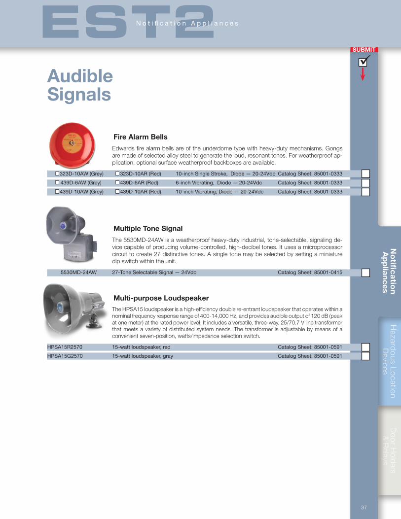
Hazard
ous Lo
cation
Devices
Do
or H
olders &
Relays
37
No
tific
atio
n A
pp
liances
SUBMIT
ü
EST2N o t i fi c a t i o n A p p l i a n c e s
Fire Alarm Bells
Edwards fire alarm bells are of the underdome type with heavy-duty mechanisms. Gongs are made of selected alloy steel to generate the loud, resonant tones. For weatherproof ap-plication, optional surface weatherproof backboxes are available.
323D-10AW (Grey) 323D-10AR (Red) 10-inch Single Stroke, Diode — 20-24Vdc Catalog Sheet: 85001-0333
439D-6AW (Grey) 439D-6AR (Red) 6-inch Vibrating, Diode — 20-24Vdc Catalog Sheet: 85001-0333
439D-10AW (Grey) 439D-10AR (Red) 10-inch Vibrating, Diode — 20-24Vdc Catalog Sheet: 85001-0333
Multiple Tone Signal
The 5530MD-24AW is a weatherproof heavy-duty industrial, tone-selectable, signaling de-vice capable of producing volume-controlled, high-decibel tones. It uses a microprocessor circuit to create 27 distinctive tones. A single tone may be selected by setting a miniature dip switch within the unit.
5530MD-24AW 27-Tone Selectable Signal — 24Vdc Catalog Sheet: 85001-0415
Multi-purpose LoudspeakerThe HPSA15 loudspeaker is a high-efficiency double re-entrant loudspeaker that operates within a nominal frequency response range of 400-14,000 Hz, and provides audible output of 120 dB (peak at one meter) at the rated power level. It includes a versatile, three-way, 25/70.7 V line transformer that meets a variety of distributed system needs. The transformer is adjustable by means of a convenient seven-position, watts/impedance selection switch.
HPSA15R2570 15-watt loudspeaker, red Catalog Sheet: 85001-0591
HPSA15G2570 15-watt loudspeaker, gray Catalog Sheet: 85001-0591
Audible Signals
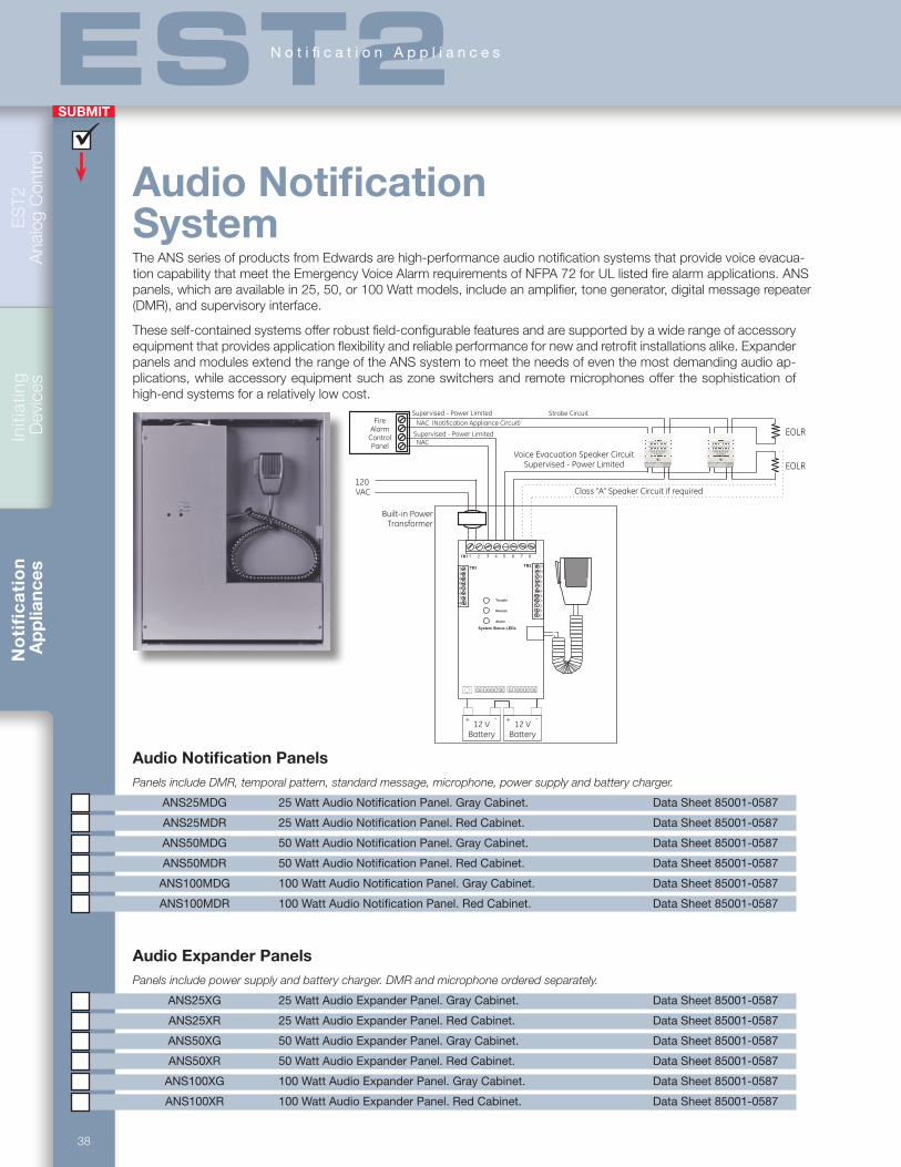
38
ES
T2
Ana
log
Con
trol
Initi
atin
g D
evic
esN
oti
fic
ati
on
Ap
plia
nces
SUBMIT
ü
EST2N o t i fi c a t i o n A p p l i a n c e s
Audio Notification SystemThe ANS series of products from Edwards are high-performance audio notification systems that provide voice evacua-tion capability that meet the Emergency Voice Alarm requirements of NFPA 72 for UL listed fire alarm applications. ANS panels, which are available in 25, 50, or 100 Watt models, include an amplifier, tone generator, digital message repeater (DMR), and supervisory interface.
These self-contained systems offer robust field-configurable features and are supported by a wide range of accessory equipment that provides application flexibility and reliable performance for new and retrofit installations alike. Expander panels and modules extend the range of the ANS system to meet the needs of even the most demanding audio ap-plications, while accessory equipment such as zone switchers and remote microphones offer the sophistication of high-end systems for a relatively low cost.
NAC (Notification Appliance Circuit)
TB1
TB3TB2
5
1
2
3
4
6
7
8
1
2
3
4
5
6
7
8
9
10
11
2 3 4 5 6 7 81 2 3 4 5 6 7 81
1 2 3 4 5 6 7 8
Normal
Alarm
Trouble
System Status LEDs
FireAlarm
ControlPanel
FIRE
FIRE
EOLR
Voice Evacuation Speaker CircuitSupervised - Power Limited
Supervised - Power Limited
Supervised - Power Limited
EOLR
120VAC
Strobe Circuit
NAC
Class “A” Speaker Circuit if required
Built-in PowerTransformer
12 VBattery
+ - + -12 V
Battery
Audio Notification PanelsPanels include DMR, temporal pattern, standard message, microphone, power supply and battery charger.
ANS25MDG 25 Watt Audio Notification Panel. Gray Cabinet. Data Sheet 85001-0587
ANS25MDR 25 Watt Audio Notification Panel. Red Cabinet. Data Sheet 85001-0587
ANS50MDG 50 Watt Audio Notification Panel. Gray Cabinet. Data Sheet 85001-0587
ANS50MDR 50 Watt Audio Notification Panel. Red Cabinet. Data Sheet 85001-0587
ANS100MDG 100 Watt Audio Notification Panel. Gray Cabinet. Data Sheet 85001-0587
ANS100MDR 100 Watt Audio Notification Panel. Red Cabinet. Data Sheet 85001-0587
Audio Expander PanelsPanels include power supply and battery charger. DMR and microphone ordered separately.
ANS25XG 25 Watt Audio Expander Panel. Gray Cabinet. Data Sheet 85001-0587
ANS25XR 25 Watt Audio Expander Panel. Red Cabinet. Data Sheet 85001-0587
ANS50XG 50 Watt Audio Expander Panel. Gray Cabinet. Data Sheet 85001-0587
ANS50XR 50 Watt Audio Expander Panel. Red Cabinet. Data Sheet 85001-0587
ANS100XG 100 Watt Audio Expander Panel. Gray Cabinet. Data Sheet 85001-0587
ANS100XR 100 Watt Audio Expander Panel. Red Cabinet. Data Sheet 85001-0587

Hazard
ous Lo
cation
Devices
Do
or H
olders &
Relays
39
No
tific
atio
n A
pp
liances
SUBMIT
ü
EST2N o t i fi c a t i o n A p p l i a n c e s
Firefighters’ TelephonesFirefighters’ telephones are typically installed in corridors, lobbies, mechanical rooms, stairways, or other stategic locations. When lifted from its cradle, or plugged into a suitable wall jack, the hand-set activates audible and visible signals at the EST2 control panel.
Edwards fire alarm telephones are rugged communications de-vices for emergency use. Enclosed keylocked telephone stations comprise three separately ordered components: the handset assembly, the frontplate, and the wallbox. Depending on how the phones are wired, they are supervised for three or four state operation. Frontplates are available with either metal or break glass insterts.
MEA approved warden stations feature doors with magnetic latches and one-state handsets with armoured cords. Warden stations mount to 6832-1 wallboxes. Portable handsets plug into one-gang receptacles. Handsets are available in black or red. The TCS-6 cabinet provides storage for up to six handsets.
6831-46831-1 6830-1 6830-3
6833-1
6830-NY-S
6832-1
Firefighters’ Telephones 6830-NY-F4 Four-state Remote Telephone Warden Station - Flush. Armored armored cord.
6830-NY-S4 Four-state Remote Telephone Warden Station - Surface. Armored armored cord.
6830-NY-F Remote Telephone Warden Station - Flush. Armored cord.
6830-5A-4 Four-state Telephone Handset Assembly - Red, 60” (1500mm) Coiled Cord, Push-to-talk button.
6830-6A-4 Four-state Telephone Handset Assembly - Red, 60” (1500mm) Armored Cord, Push-to-talk button.
6830-1 Telephone Handset Assembly - Red c/w 60” (1500mm) Coiled Cord.
6830-4 Four-state Telephone Handset Assembly - Red, 60” (1500mm) Coiled Cord.
6830-5A Three-state Telephone Handset Assembly - Red, 60” (1500mm) Coiled Cord, Push-to-talk button.
6830-6A Three-state Telephone Handset Assembly - Red, 60” (1500mm) Armored Cord, Push-to-talk button.
6833-4 Four-state Portable Telephone Handset Receptacle, 1-gang Stainless-steel Faceplate.
6833-1 Portable Telephone Handset Receptacle, 1-gang Stainless-steel Faceplate.
6830-3 Portable Telephone Handset - Black c/w 60” (1500mm) Coiled Cord.
6700-0061 Portable Telephone Handset - Red c/w 60” (1500mm) Coiled Cord.
6831-1 Frontplate - Flush Mount, Red Finish, Break Glass Type c/w 2 keys.
6831-2 Frontplate - Flush Mount, Red Finish, Non-Break Glass Type c/w 2 keys.
6831-3 Frontplate - Surface Mount Red Finish, Break Glass Type c/w 2 keys.
6831-4 Frontplate - Surface Mounting Red Finish, Non-Break Glass Type c/w 2 keys.
6832-1 Wallbox - Flush or Surface mount, Red finish. 14” (356mm) H x 8-1/2” (216mm) W x 3½” (89mm) D.
TCS-6 Portable handset storage cabinet. Surface mount c/w keylock. Red finish with white lettering.
TB1
1
2
3
5
6
7
8
4
Compatible signalmodule.
Printed circuit board
24 Vdc
24 Vdc
UL/ULC listedpower supply
Telephone riser
Control relay module to operateTelephone in Use indicator light.
47 kW
Normal(on hook)
TB1
1
2
3
5
6
7
8
4
Compatible signalmodule.
Printed circuit board
24 Vdc
24 Vdc
UL/ULC listedpower supply
Telephoneriser
Control relay module to operateTelephone in Use indicator light.
47 kW
Normal(on hook)
Active(off hook)
Three-state operation
Four-state operation
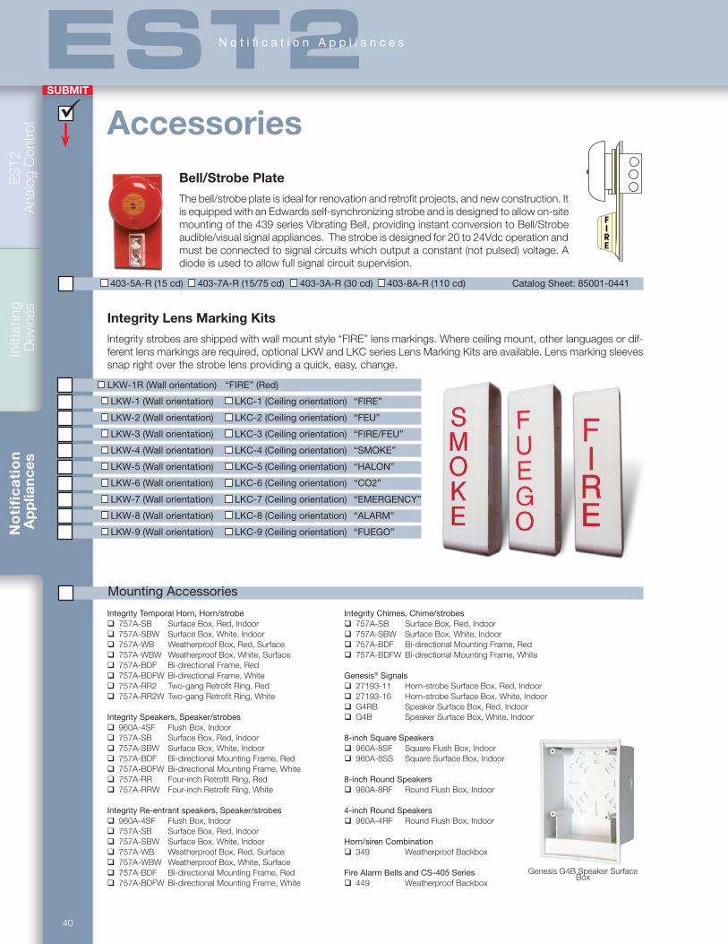
40
ES
T2
Ana
log
Con
trol
Initi
atin
g D
evic
esN
oti
fic
ati
on
Ap
plia
nces
SUBMIT
ü
EST2N o t i fi c a t i o n A p p l i a n c e s
Integrity Lens Marking Kits
Integrity strobes are shipped with wall mount style “FIRE” lens markings. Where ceiling mount, other languages or dif-ferent lens markings are required, optional LKW and LKC series Lens Marking Kits are available. Lens marking sleeves snap right over the strobe lens providing a quick, easy, change.
LKW-1R (Wall orientation) “FIRE” (Red)
LKW-1 (Wall orientation) LKC-1 (Ceiling orientation) “FIRE”
LKW-2 (Wall orientation) LKC-2 (Ceiling orientation) “FEU”
LKW-3 (Wall orientation) LKC-3 (Ceiling orientation) “FIRE/FEU”
LKW-4 (Wall orientation) LKC-4 (Ceiling orientation) “SMOKE”
LKW-5 (Wall orientation) LKC-5 (Ceiling orientation) “HALON”
LKW-6 (Wall orientation) LKC-6 (Ceiling orientation) “CO2”
LKW-7 (Wall orientation) LKC-7 (Ceiling orientation) “EMERGENCY”
LKW-8 (Wall orientation) LKC-8 (Ceiling orientation) “ALARM”
LKW-9 (Wall orientation) LKC-9 (Ceiling orientation) “FUEGO”
Integrity Temporal Horn, Horn/strobe 757A-SB Surface Box, Red, Indoor 757A-SBW Surface Box, White, Indoor 757A-WB Weatherproof Box, Red, Surface 757A-WBW Weatherproof Box, White, Surface 757A-BDF Bi-directional Frame, Red 757A-BDFW Bi-directional Frame, White 757A-RR2 Two-gang Retrofit Ring, Red 757A-RR2W Two-gang Retrofit Ring, White
Integrity Speakers, Speaker/strobes 960A-4SF Flush Box, Indoor 757A-SB Surface Box, Red, Indoor 757A-SBW Surface Box, White, Indoor 757A-BDF Bi-directional Mounting Frame, Red 757A-BDFW Bi-directional Mounting Frame, White 757A-RR Four-inch Retrofit Ring, Red 757A-RRW Four-inch Retrofit Ring, White
Integrity Re-entrant speakers, Speaker/strobes 960A-4SF Flush Box, Indoor 757A-SB Surface Box, Red, Indoor 757A-SBW Surface Box, White, Indoor 757A-WB Weatherproof Box, Red, Surface 757A-WBW Weatherproof Box, White, Surface 757A-BDF Bi-directional Mounting Frame, Red 757A-BDFW Bi-directional Mounting Frame, White
Mounting Accessories
Integrity Chimes, Chime/strobes 757A-SB Surface Box, Red, Indoor 757A-SBW Surface Box, White, Indoor 757A-BDF Bi-directional Mounting Frame, Red 757A-BDFW Bi-directional Mounting Frame, White
Genesis® Signals 27193-11 Horn-strobe Surface Box, Red, Indoor 27193-16 Horn-strobe Surface Box, White, Indoor G4RB Speaker Surface Box, Red, Indoor G4B Speaker Surface Box, White, Indoor
8-inch Square Speakers 960A-8SF Square Flush Box, Indoor 960A-8SS Square Surface Box, Indoor
8-inch Round Speakers 960A-8RF Round Flush Box, Indoor
4-inch Round Speakers 960A-4RF Round Flush Box, Indoor
Horn/siren Combination 349 Weatherproof Backbox
Fire Alarm Bells and CS-405 Series 449 Weatherproof Backbox
Bell/Strobe Plate
The bell/strobe plate is ideal for renovation and retrofit projects, and new construction. It is equipped with an Edwards self-synchronizing strobe and is designed to allow on-site mounting of the 439 series Vibrating Bell, providing instant conversion to Bell/Strobe audible/visual signal appliances. The strobe is designed for 20 to 24Vdc operation and must be connected to signal circuits which output a constant (not pulsed) voltage. A diode is used to allow full signal circuit supervision.
403-5A-R (15 cd) 403-7A-R (15/75 cd) 403-3A-R (30 cd) 403-8A-R (110 cd) Catalog Sheet: 85001-0441
Accessories
Genesis G4B Speaker Surface Box
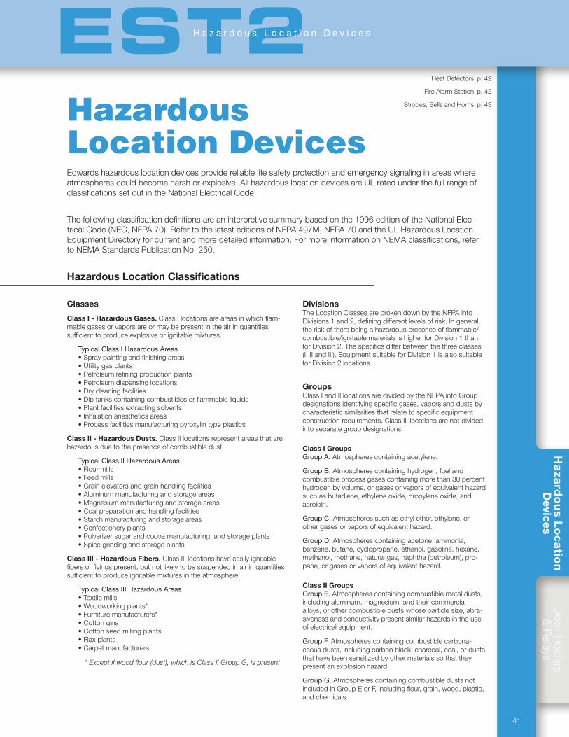
Hazardous Location Devices
HeatDetectors p.42
FireAlarmStation p.42
Strobes,BellsandHorns p.43
Classes
Class I - Hazardous Gases.ClassIlocationsareareasinwhichflam-mablegasesorvaporsareormaybepresentintheairinquantitiessufficienttoproduceexplosiveorignitablemixtures.
Typical Class I Hazardous Areas•Spraypaintingandfinishingareas•Utilitygasplants•Petroleumrefiningproductionplants•Petroleumdispensinglocations•Drycleaningfacilities•Diptankscontainingcombustiblesorflammableliquids•Plantfacilitiesextractingsolvents•Inhalationanestheticsareas•Processfacilitiesmanufacturingpyroxylintypeplastics
Class II - Hazardous Dusts.ClassIIlocationsrepresentareasthatarehazardousduetothepresenceofcombustibledust.
Typical Class II Hazardous Areas•Flourmills•Feedmills•Grainelevatorsandgrainhandlingfacilities•Aluminummanufacturingandstorageareas•Magnesiummanufacturingandstorageareas•Coalpreparationandhandlingfacilities•Starchmanufacturingandstorageareas•Confectioneryplants•Pulverizersugarandcocoamanufacturing,andstorageplants•Spicegrindingandstorageplants
Class III - Hazardous Fibers. ClassIIIlocationshaveeasilyignitablefibersorflyingspresent,butnotlikelytobesuspendedinairinquantitiessufficienttoproduceignitablemixturesintheatmosphere.
Typical Class III Hazardous Areas•Textilemills•Woodworkingplants*•Furnituremanufacturers*•Cottongins•Cottonseedmillingplants•Flaxplants•Carpetmanufacturers
* Except if wood flour (dust), which is Class II Group G, is present
DivisionsTheLocationClassesarebrokendownbytheNFPAintoDivisions1and2,definingdifferentlevelsofrisk.Ingeneral,theriskoftherebeingahazardouspresenceofflammable/combustible/ignitablematerialsishigherforDivision1thanforDivision2.Thespecificsdifferbetweenthethreeclasses(I,IIandIII).EquipmentsuitableforDivision1isalsosuitableforDivision2locations.
GroupsClassIandIIlocationsaredividedbytheNFPAintoGroupdesignationsidentifyingspecificgases,vaporsanddustsbycharacteristicsimilaritiesthatrelatetospecificequipmentconstructionrequirements.ClassIIIlocationsarenotdividedintoseparategroupdesignations.
Class I Groups Group A.Atmospherescontainingacetylene.
Group B. Atmospherescontaininghydrogen,fuelandcombustibleprocessgasescontainingmorethan30percenthydrogenbyvolume,orgasesorvaporsofequivalenthazardsuchasbutadiene,ethyleneoxide,propyleneoxide,andacrolein.
Group C. Atmospheressuchasethylether,ethylene,orothergasesorvaporsofequivalenthazard.
Group D.Atmospherescontainingacetone,ammonia,benzene,butane,cyclopropane,ethanol,gasoline,hexane,methanol,methane,naturalgas,naphtha(petroleum),pro-pane,orgasesorvaporsofequivalenthazard.
Class II GroupsGroup E. Atmospherescontainingcombustiblemetaldusts,includingaluminum,magnesium,andtheircommercialalloys,orothercombustibledustswhoseparticlesize,abra-sivenessandconductivitypresentsimilarhazardsintheuseofelectricalequipment.
Group F.Atmospherescontainingcombustiblecarbona-ceousdusts,includingcarbonblack,charcoal,coal,orduststhathavebeensensitizedbyothermaterialssothattheypresentanexplosionhazard.
Group G. AtmospherescontainingcombustibledustsnotincludedinGroupEorF,includingflour,grain,wood,plastic,andchemicals.
Edwardshazardouslocationdevicesprovidereliablelifesafetyprotectionandemergencysignalinginareaswhereatmospherescouldbecomeharshorexplosive.AllhazardouslocationdevicesareULratedunderthefullrangeofclassificationssetoutintheNationalElectricalCode.
Thefollowingclassificationdefinitionsareaninterpretivesummarybasedonthe1996editionoftheNationalElec-tricalCode(NEC,NFPA70).RefertothelatesteditionsofNFPA497M,NFPA70andtheULHazardousLocationEquipmentDirectoryforcurrentandmoredetailedinformation.FormoreinformationonNEMAclassifications,refertoNEMAStandardsPublicationNo.250.
Hazardous Location Classifications
Hazardous Location Devices
Ha
zard
ou
s Lo
ca
tion
Devices
Do
orH
olders&
Relays
41
EST2H a z a r d o u s L o c a t i o n D e v i c e s

ES
T2
Ana
log
Con
trol
Initi
atin
gD
evic
esN
otifi
catio
nA
pplia
nces
Ha
zard
ou
s L
oc
ati
on
Dev
ices
SUBMIT
42
EST2H a z a r d o u s L o c a t i o n D e v i c e s
Rate Compensation Heat Detectors
Series302heatdetectorsaredesignedforuseinnormalenvironmentsaswellasenvironmentswherethedetectorsaresubjecttoweather,moisture(internalcondensation),andexplosiveatmospheres.Theyarenormally-opendevicesdesignedtocloseanelectricalcircuituponactivation.Allmodelsfeatureratecompensationandareavailablewitheither135°F(57.2°C)or194°F(90°C)ratings.Theyareselfrestoring,hermeticallysealed,shockandcorrosionresistant,andaretamperproof.
Sensorsratedat135°F(57.2°C)willnotrespondtomomentarytemperaturefluctuationslessthan30°F/minutebetween60°F(16°C)and100°F(38°C).Sensorsratedat194°F(90°C)willnotrespondtomomentarytemperaturefluctuationslessthan50°F/minutebetween60°F(16°C)and150°F(66°C).302Seriessensorsshouldnotbeusedinenvironmentswhereconditionsexceedtheseparameters.Donotinstalltheminhotairducts,infrontofheaters,inpaintboothsthatuseheattocurepaint,oranyotherlocationsubjecttotem-peraturefluctuation.
Sensor’s Rated Temperature
Minimum Ambient Air Temperature
Maximum Ceiling Temperature
135°F(57.2°C) -40°F(-40°C) 100°F(38°C)194°F(90°C) -40°F(-40°C) 150°F(66°C)
Thesensor'saluminumtubeactsasaheatcollectorwhensourcesofheatradiatedirectlyonthetube.Installthesesensorsoutofdirectsunlightandawayfromradiatingheatsourcesincludingthedirectflowfromheatersandheatducts.
302-AW-135 All-weather Heat Detector - Vertical Mounting FM & UL, 135 °F (57.2 °C) Data Sheet 85001-0589
302-AW-194 All-weather Heat Detector - Vertical Mounting FM & UL, 194°F (90 °C) Data Sheet 85001-0589
302-ET-135 All-weather Heat Detector - Vertical, Box Mount (½" NPT), FM & UL, 135 °F (57.2 °C) Data Sheet 85001-0589
302-ET-194 All-weather Heat Detector - Vertical, Box Mount (½" NPT), FM & UL, 194°F (90 °C) Data Sheet 85001-0589
302-EPM-135 Heat Detector - Explosionproof Mounting UL (Not FM approved), 135 °F (57.2 °C) Data Sheet 85001-0589
302-EPM-194 Heat Detector - Explosionproof Mounting UL (not FM approved), 194°F (90 °C) Data Sheet 85001-0589
AP-P Adaptor plate for mounting 302 and 302-AW to any 3" box or 4" octagon outlet box Data Sheet 85001-0589
STONCO27 3 ½" Weatherproof, round backbox and cover Data Sheet 85001-0589
JALX11 Explosion proof outlet body with cover - Killark Data Sheet 85001-0589
Hazardous location fire alarm station
TheXAL-53isanextremelyruggeddouble-actionfirealarmstationsuitableforhazardouslocations.Thedeviceisactivatedbyliftingthefrontcoverandpullingdownthering.Thistwo-stepprocesspreventsunintentionaloperation.
XAL-53 Hazardous Location Fire Alarm Station Catalog Sheet: 85001-0371
Initiating Devices
Surface Mount
Box mount
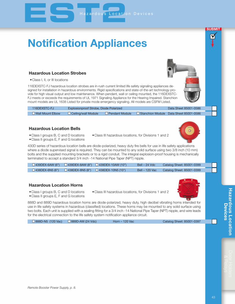
Ha
zard
ou
s Lo
ca
tion
Devices
Do
orH
olders&
Relays
43
SUBMIT
EST2H a z a r d o u s L o c a t i o n D e v i c e s
Hazardous Location Strobes
•ClassI,II,orIIIlocations
116DEXSTC-FJhazardouslocationstrobesarein-rushcurrentlimitedlifesafetysignalingappliancesde-signedforinstallationinhazardousenvironments.Rigidspecificationsandstate-of-the-arttechnologypro-videforhighvisualoutputandlowmaintenance.Whenpendant,wallorceilingmounted,the116DEXSTC-FJmeetsorexceedstherequirementsofUL1971SignalingAppliancefortheHearingImpaired.StanchionmountmodelsareUL1638Listedforprivatemodeemergencysignaling.AllmodelsareCSFMListed.
116DEXSTC-FJ Explosionproof Strobe, Diode Polarized Data Sheet 85001-0586
Wall Mount Elbow Ceiling/wall Module Pendant Module Stanchion Module Data Sheet 85001-0586
Hazardous Location Bells
•ClassIgroupsB,CandDlocations •ClassIIIhazardouslocations,forDivisions1and2•ClassIIgroupsE,FandGlocations
430Dseriesofhazardouslocationbellsarediode-polarized,heavydutyfirebellsforuseinlifesafetyapplicationswhereadiodesupervisedsignalisrequired.Theycanbemountedtoanysolidsurfaceusingtwo3/8inch(10mm)boltsandthesuppliedmountingbracketsortoarigidconduit.Theintegralexplosion-proofhousingismechanicallyterminatedtoacceptastandard3/4inch-14NationalPipeTaper(NPT)nipple.
439DEX-6AW (6”) 439DEX-8AW (8”) 439DEX-10AW (10”) Bell – 24 Vdc Catalog Sheet: 85001-0399
438DEX-6N5 (6") 438DEX-8N5 (8") 438DEX-10N5 (10") Bell – 120 Vac Catalog Sheet: 85001-0399
Hazardous Location Horns
•ClassIgroupsB,CandDlocations •ClassIIIhazardouslocations,forDivisions1and2•ClassIIgroupsE,FandGlocations
888Dand889Dhazardouslocationhornsarediode-polarized,heavyduty,highdecibelvibratinghornsintendedforuseinlifesafetysystemsinhazardous(classified)locations.Thesehornsmaybemountedtoanysolidsurfaceusingtwobolts.Eachunitissuppliedwithasealingfittingfora3/4inch-14NationalPipeTaper(NPT)nipple,andwireleadsfortheelectricalconnectiontothelifesafetysystemnotificationappliancecircuit.
888D-N5 (120 Vac) 889D-AW (24 Vdc) Horn – 120 Vac Catalog Sheet: 85001-0397
Notification Appliances
Remote Booster Power Supply, p. 8.
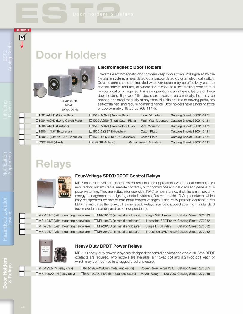
Do
or
Ho
lder
s
& R
elay
s
44
ES
T2
Ana
log
Con
trol
Initi
atin
g D
evic
esN
otifi
catio
n A
pplia
nces
Haz
ard
ous
Lo
catio
n D
evic
es
SUBMIT
EST2D o o r H o l d e r s & R e l a y s
Door Holders Electromagnetic Door Holders
Edwards electromagnetic door holders keep doors open until signaled by the fire alarm system, a heat detector, a smoke detector, or an electrical switch. Door holders should be installed wherever doors may be effectively used to confine smoke and fire, or where the release of a self-closing door from a remote location is required. Fail-safe operation is an inherent feature of these door holders. If power fails, doors are released automatically, but may be opened or closed manually at any time. All units are free of moving parts, are self-contained, and require no maintenance. Door holders have a holding force of approximately 15-25 Lbf (66-111N).
1501-AQN5 (Single Door) 1502-AQN5 (Double Door) Floor Mounted Catalog Sheet: 85001-0421
1504-AQN5 (Long Catch Plate) 1505-AQN5 (Short Catch Plate) Flush Wall Mounted Catalog Sheet: 85001-0421
1508-AQN5 (Surface) 1505-AQN9 (Completely flush) Wall Mounted Catalog Sheet: 85001-0421
1500-1 (1.5” Extension) 1500-2 (2.5” Extension) Catch Plate Catalog Sheet: 85001-0421
1500-7 (5.25 to 7.5” Extension) 1500-12 (7.5 to 12” Extension) Catch Plate Catalog Sheet: 85001-0421
CS2595-5 (short) CS2598-5 (long) Replacement Armature Catalog Sheet: 85001-0421
Relays Four-Voltage SPDT/DPDT Control Relays
MR Series multi-voltage control relays are ideal for applications where local contacts are required for system status, remote contacts, or for control of electrical loads and general pur-pose switching. They are suitable for use with HVAC temperature control, fire alarm, security, energy management, and lighting control systems. Relays provide 10-Amp contacts, which may be operated by one of four input control voltages. Each relay position contains a red LED that indicates the relay coil is energized. Relays may be snapped apart from a standard four-module assembly and used independently.
MR-101/T (with mounting hardware) MR-101/C (in metal enclosure) Single SPDT relay Catalog Sheet: 270062
MR-104/T (with mounting hardware) MR-104/C (in metal enclosure) 4-position SPDT relay Catalog Sheet: 270062
MR-201/T (with mounting hardware) MR-201/C (in metal enclosure) Single DPDT relay Catalog Sheet: 270062
MR-204/T (with mounting hardware) MR-204/C (in metal enclosure) 4-position DPDT relay Catalog Sheet: 270062
Heavy Duty DPDT Power Relays
MR-199 heavy duty power relays are designed for control applications where 30-Amp DPDT contacts are required. Two models are available: a 115Vac coil and a 24Vdc coil, each of which may be mounted in a rugged steel enclosure.
MR-199X-13 (relay only) MR-199X-13/C (in metal enclosure) Power Relay — 24 VDC Catalog Sheet: 270065
MR-199AX-14 (relay only) MR-199AX-14/C (in metal enclosure) Power Relay — 120 VDC Catalog Sheet: 270065
24 Vac 60 Hz
24 Vdc
120 Vac 60 Hz
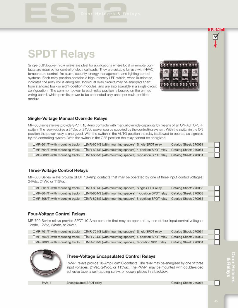
Do
or H
old
ers &
Relays
45
SUBMIT
EST2D o o r H o l d e r s & R e l a y s
SPDT RelaysSingle-pull/double-throw relays are ideal for applications where local or remote con-tacts are required for control of electrical loads. They are suitable for use with HVAC, temperature control, fire alarm, security, energy management, and lighting control systems. Each relay position contains a high-intensity LED which, when illuminated, indicates the relay coil is energized. Individual relay circuits may be snapped apart from standard four- or eight-position modules, and are also available in a single-circuit configuration. The common power to each relay position is bussed on the printed wiring board, which permits power to be connected only once per multi-position module.
Single-Voltage Manual Override Relays
MR-600 series relays provide SPDT, 10-Amp contacts with manual override capability by means of an ON-AUTO-OFF switch. The relay requires a 24Vac or 24Vdc power source supplied by the controlling system. With the switch in the ON position the power relay is energized. With the switch in the AUTO position the relay is allowed to operate as signaled by the controlling system. With the switch in the OFF position the relay cannot be energized.
MR-601/T (with mounting track) MR-601/S (with mounting spacers) Single SPDT relay Catalog Sheet: 270061
MR-604/T (with mounting track) MR-604/S (with mounting spacers) 4-position SPDT relay Catalog Sheet: 270061
MR-608/T (with mounting track) MR-608/S (with mounting spacers) 8-position SPDT relay Catalog Sheet: 270061
Three-Voltage Control Relays
MR-800 Series relays provide SPDT 10-Amp contacts that may be operated by one of three input control voltages: 24Vdc, 24Vac or 115Vac.
MR-801/T (with mounting track) MR-801/S (with mounting spacers) Single SPDT relay Catalog Sheet: 270063
MR-804/T (with mounting track) MR-804/S (with mounting spacers) 4-position SPDT relay Catalog Sheet: 270063
MR-808/T (with mounting track) MR-808/S (with mounting spacers) 8-position SPDT relay Catalog Sheet: 270063
Four-Voltage Control Relays
MR-700 Series relays provide SPDT 10-Amp contacts that may be operated by one of four input control voltages: 12Vdc, 12Vac, 24Vdc, or 24Vac.
MR-701/T (with mounting track) MR-701/S (with mounting spacers) Single SPDT relay Catalog Sheet: 270064
MR-704/T (with mounting track) MR-704/S (with mounting spacers) 4-position SPDT relay Catalog Sheet: 270064
MR-708/T (with mounting track) MR-708/S (with mounting spacers) 8-position SPDT relay Catalog Sheet: 270064
Three-Voltage Encapsulated Control Relays
PAM-1 relays provide 10-Amp Form C contacts. The relay may be energized by one of three input voltages: 24Vac, 24Vdc, or 115Vac. The PAM-1 may be mounted with double-sided adhesive tape, a self-tapping screw, or loosely placed in a backbox.
PAM-1 Encapsulated SPDT relay Catalog Sheet: 270066
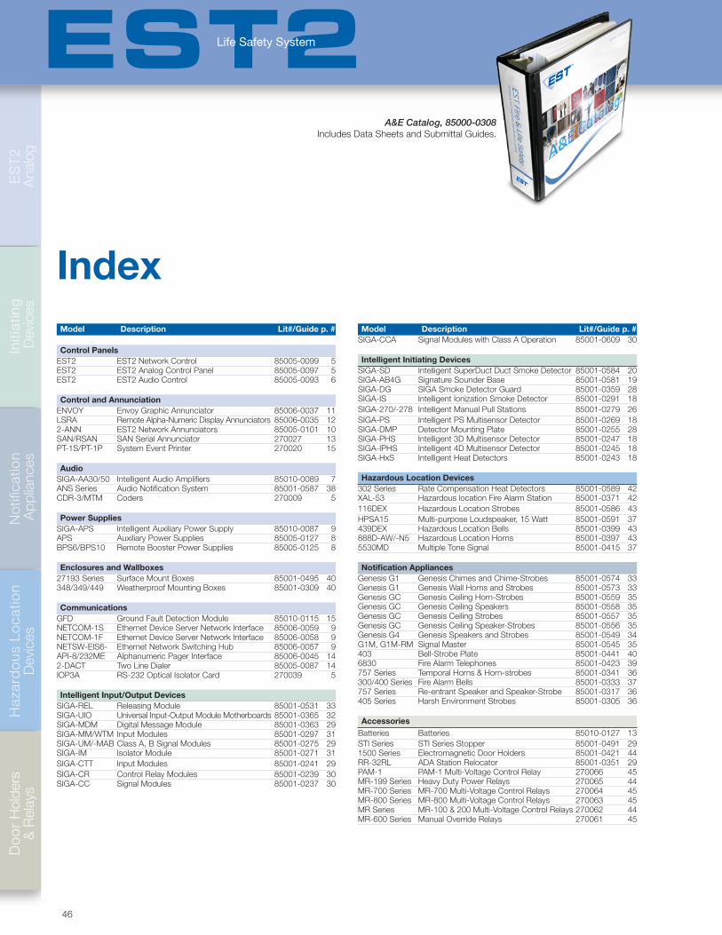
46
Do
or
Hol
ders
&
Rel
ays
ES
T2
A
nalo
gIn
itiat
ing
Dev
ices
Not
ifica
tion
App
lianc
esH
azar
do
us L
oca
tion
Dev
ices
EST2Life Safety System
IndexModel Description Lit#/Guide p. #
Control PanelsEST2 EST2 Network Control 85005-0099 5EST2 EST2 Analog Control Panel 85005-0097 5EST2 EST2 Audio Control 85005-0093 6
Control and AnnunciationENVOY Envoy Graphic Annunciator 85006-0037 11LSRA Remote Alpha-Numeric Display Annunciators 85006-0035 122-ANN EST2 Network Annunciators 85005-0101 10SAN/RSAN SAN Serial Annunciator 270027 13PT-1S/PT-1P System Event Printer 270020 15
AudioSIGA-AA30/50 Intelligent Audio Amplifiers 85010-0089 7ANS Series Audio Notification System 85001-0587 38CDR-3/MTM Coders 270009 5
Power SuppliesSIGA-APS Intelligent Auxiliary Power Supply 85010-0087 9APS Auxiliary Power Supplies 85005-0127 8BPS6/BPS10 Remote Booster Power Supplies 85005-0125 8
Enclosures and Wallboxes27193 Series Surface Mount Boxes 85001-0495 40348/349/449 Weatherproof Mounting Boxes 85001-0309 40
CommunicationsGFD Ground Fault Detection Module 85010-0115 15NETCOM-1S Ethernet Device Server Network Interface 85006-0059 9NETCOM-1F Ethernet Device Server Network Interface 85006-0058 9NETSW-EIS6- Ethernet Network Switching Hub 85006-0057 9API-8/232ME Alphanumeric Pager Interface 85006-0045 142-DACT Two Line Dialer 85005-0087 14IOP3A RS-232 Optical Isolator Card 270039 5
Intelligent Input/Output DevicesSIGA-REL Releasing Module 85001-0531 33SIGA-UIO Universal Input-Output Module Motherboards 85001-0365 32SIGA-MDM Digital Message Module 85001-0363 29SIGA-MM/WTM Input Modules 85001-0297 31SIGA-UM/-MAB Class A, B Signal Modules 85001-0275 29SIGA-IM Isolator Module 85001-0271 31SIGA-CTT Input Modules 85001-0241 29SIGA-CR Control Relay Modules 85001-0239 30SIGA-CC Signal Modules 85001-0237 30
Model Description Lit#/Guide p. #SIGA-CCA Signal Modules with Class A Operation 85001-0609 30
Intelligent Initiating DevicesSIGA-SD Intelligent SuperDuct Duct Smoke Detector 85001-0584 20SIGA-AB4G Signature Sounder Base 85001-0581 19SIGA-DG SIGA Smoke Detector Guard 85001-0359 28SIGA-IS Intelligent Ionization Smoke Detector 85001-0291 18SIGA-270/-278 Intelligent Manual Pull Stations 85001-0279 26SIGA-PS Intelligent PS Multisensor Detector 85001-0269 18SIGA-DMP Detector Mounting Plate 85001-0255 28SIGA-PHS Intelligent 3D Multisensor Detector 85001-0247 18SIGA-IPHS Intelligent 4D Multisensor Detector 85001-0245 18SIGA-HxS Intelligent Heat Detectors 85001-0243 18
Hazardous Location Devices302 Series Rate Compensation Heat Detectors 85001-0589 42XAL-53 Hazardous location Fire Alarm Station 85001-0371 42116DEX Hazardous Location Strobes 85001-0586 43HPSA15 Multi-purpose Loudspeaker, 15 Watt 85001-0591 37439DEX Hazardous Location Bells 85001-0399 43888D-AW/-N5 Hazardous Location Horns 85001-0397 435530MD Multiple Tone Signal 85001-0415 37
Notification AppliancesGenesis G1 Genesis Chimes and Chime-Strobes 85001-0574 33Genesis G1 Genesis Wall Horns and Strobes 85001-0573 33Genesis GC Genesis Ceiling Horn-Strobes 85001-0559 35Genesis GC Genesis Ceiling Speakers 85001-0558 35Genesis GC Genesis Ceiling Strobes 85001-0557 35Genesis GC Genesis Ceiling Speaker-Strobes 85001-0556 35Genesis G4 Genesis Speakers and Strobes 85001-0549 34G1M, G1M-RM Signal Master 85001-0545 35403 Bell-Strobe Plate 85001-0441 406830 Fire Alarm Telephones 85001-0423 39757 Series Temporal Horns & Horn-strobes 85001-0341 36300/400 Series Fire Alarm Bells 85001-0333 37757 Series Re-entrant Speaker and Speaker-Strobe 85001-0317 36405 Series Harsh Environment Strobes 85001-0305 36
AccessoriesBatteries Batteries 85010-0127 13STI Series STI Series Stopper 85001-0491 291500 Series Electromagnetic Door Holders 85001-0421 44RR-32RL ADA Station Relocator 85001-0351 29PAM-1 PAM-1 Multi-Voltage Control Relay 270066 45MR-199 Series Heavy Duty Power Relays 270065 44MR-700 Series MR-700 Multi-Voltage Control Relays 270064 45MR-800 Series MR-800 Multi-Voltage Control Relays 270063 45MR Series MR-100 & 200 Multi-Voltage Control Relays 270062 44MR-600 Series Manual Override Relays 270061 45
A&E Catalog, 85000-0308Includes Data Sheets and Submittal Guides.


85005-0105, Issue 7.1
Innovation, leadership, and a rich tradition of excellence
Whether EST life safety systems are protecting the lives and livelihoods of the
people who make businesses run, or the lives entrusted to the care of public
institutions; whether they’re charged with protecting the guests of the world’s
finest hotels, or preserving irreplaceable artifacts that bring history to life; EST
stands alone as the brand closely associated with some of the most important
and far-reaching developments in the life safety industry today.
Our strength is in our Strategic Partners — the people and organizations
we entrust with the technology that has charted the course of life safety protec-
tion for decades. Strategic Partners are not middlemen or go-betweens. They
are independent contractors that form an integral part of the Edwards marketing
and support organization. As insiders, they enjoy exclusive access to products,
custom design innovations, specialized training, and pricing privileges. Yet
as successful independent contractors, they are adept at ensuring that each
submittal is strong and competitive, and that each bid is locally relevant to your
installation. As local businesses they not only have to earn your trust — they
have to keep it.
Together these strengths set EST installations apart, and have earned this
brand a special place among life safety and security solutions available today.
Perhaps that’s why EST products and systems have become the choice of
building owners, architects and engineers around the globe. And why many of
the world’s most cherished landmarks are protected by Edwards products that
bear the EST mark. From the Bibliotheca Alexandrina Museum in Egypt, to the
modern-day sphinx at the Luxor Hotel in Las Vegas, professionals who design,
own and occupy the world’s most impressive structures have come to know
that the safest and most survivable solution today is an EST solution.
See what’s possible now.
Contact your EST Strategic
Partner today.
Detection & alarm since 1872
U.S.T 888-378-2329F 866-503-3996
CanadaChubb-EdwardsT 519 376 2430F 519 376 7258
Southeast Asia T : +65 6391 9300 F : +65 6391 9306 India T : +91 80 4344 2000 F : +91 80 4344 2050 AustraliaT +61 3 9239 1200F +61 3 9239 1299
EuropeT +32 2 725 11 20F +32 2 721 86 13
Latin AmericaT 305 593 4301F 305 593 4300
utcfireandsecurity.com
© 2010 UTC Fire & Security. All rights reserved.