Embed Size (px)
Citation preview

8 2 0 N O V ARead the instructions before use. This control must be installed in accordance with the rules in force.9.
957.
821
001

English 133 -

3
Gas connections 3/8” NPT or 1/2” NPT
Pilot connections 7/16” UNEF
Installation position Multi-position, Never Upside down
Gas families Liquefied Petroleum Gas or Natural Gas
Maximum gas inlet pressure 1/2 PSI
Maximum outlet pressure setting range 3.5”~6” w.c. for NG and 8”~12” w.c. for LPG
Working temperature range 32 ~ 175ºF (optional 32 ~ 225ºF)
Pressure regulator Servo regulated
APPLICATION
The 820 Nova Millivolt combination gas control is an On/Offgas valve suitable for use with gas fireplaces, gas log sets,gas space heaters and other gas heating equipment.Mill ivolt control permits complete regulation of theappliance, without requiring main supply voltage.
- The True Millivolt version utilizes a thermo-generator to
power the main operator and the safety valve in B-vent
applications.
- The Mil l ivolt Plus is typically used in direct-vent
MAIN FEATURES
Three position control knob: “OFF/ PILOT / ON” (MS)
Thermo-electric flame failure device with re-start interlock (GM)
Servo controlled Pressure Regulator (PR)
Manual or electronic “HI/LO” adjustment (optional) (MA)
Millivolt Operator (EV)
Pilot outlet with flow adjustment screw (RQ)
Inlet and pilot filters (FL)
Inlet and outlet pressure test ports
applications wherethe main operator is powered by a thermo-generator and the safety
valve is powered by a thermocouple with 11/32” thermocouple connection to the safety magnet.
- The Millivolt Plus may, in some instances, also be used in vent free applications that require a
special oxygen depletion system (ODS) pilot. Valves for this application use a M8 thread for the
thermocouple connection to the safety magnet.
SPECIFICATIONS
TECHNICAL DATA
USE AN
D INSTALLATIO
N IN
STRUCTIO
NS
4
ENG
LISH
AE
P I LOT
TP
TH
TP
TH
1
5
15 67
8
2 34
MS
GM
PR
FL RQ
MAIN
PILOT
GASINLET
EV
BURNER
BURNER
FL
Versions with manual flow adjustment
MS
GM
PR
FL RQ
MAIN
PILOT
GASINLET
EV
BURNER
BURNER
FL MA
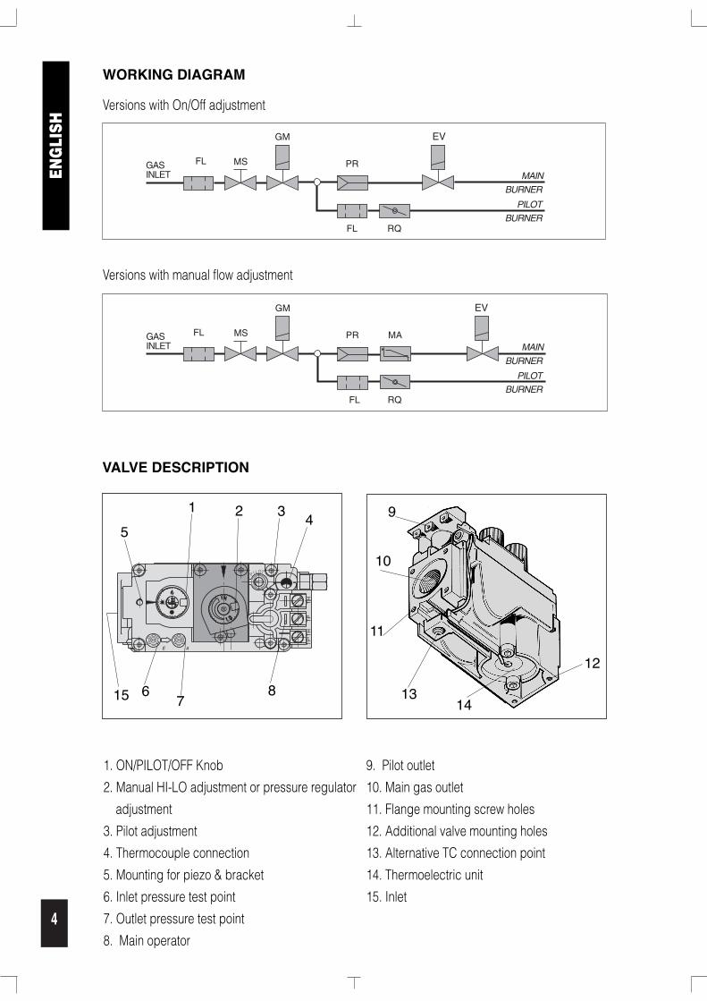
VALVE DESCRIPTION
WORKING DIAGRAM
Versions with On/Off adjustment
9
10
11
1314
12
1. ON/PILOT/OFF Knob 9. Pilot outlet
2. Manual HI-LO adjustment or pressure regulator 10. Main gas outlet
adjustment 11. Flange mounting screw holes
3. Pilot adjustment 12. Additional valve mounting holes
4. Thermocouple connection 13. Alternative TC connection point
5. Mounting for piezo & bracket 14. Thermoelectric unit
6. Inlet pressure test point 15. Inlet
7. Outlet pressure test point
8. Main operator

5
ELECTRICAL DATA
MAIN OPERATOR SPECIFICATIONS
Minimum open circuit voltage ≥ 325mV
Minimum closed circuit voltage ≥ 100mV
Operator resistance 2.25Ω ± 0.5Ω
SAFETY MAGNET SPECIFICATIONS
Coil resistance 0.015Ω ~ 0.021Ω
TYPICAL HOLD IN AND DROP OUT SPECIFICATIONS
Hold In Drop Out
True Millivolt <10mA >4mA
Millivolt Plus <285mA >125mA
Vent Free <200mA >80mA
STOP:Do not install, replace, or in any way modify the gas valve or the appliance, unlessCERTIFIED and QUALIFIED as a Gas Appliance Service Technician on the appliance thisvalve is used on. READ AND FOLLOW ALL INSTRUCTIONS.
INSTALLATION
When installation of this product begins…1. Read all of these instructions carefully. Failure to follow these instructions could damage the
product or cause a dangerous condition.2. Check the ratings given in the instructions and on the appliance to make certain that the control
is suitable for your application.3. All operations of installation, calibration, conversion and regulation must be undertaken
exclusively by a qualified and certified Gas Appliance Service Technician following theinstruction specified in this catalog and those in the instruction manual of the appliance in whichthe valve is installed.
4. After installation is complete, verify that the appliance is operating as indicated in theseinstructions.
WARNING:Oxygen Depletion Hazard.Can cause injury or death by asphyxiation.Do not use valves for vented appliances on unvented or vent free appliances. Do not usevalves for unvented or vent free appliances on vented appliances.
ENG
LISH

6
ENG
LISH
WARNING:Fire or Explosion Hazard.Can cause property damage, severe injury or death.
Follow these instructions completely.1. Turn off gas supply at the appliance service valve before installation, and perform a Gas
Leak Test after the installation is completed.2. Always install the sediment trap in the gas supply line to prevent contamination of the gas
control.3. Do not force the control knob. Use only your hand to turn the knob. If the knob does not
move by hand, the valve should be replaced by a trained service technician.
CAUTIONElectrical shock or equipment damage hazard.Can shock individuals or short equipment circuitry.Make sure to disconnect all electrical supplies before beginning the installation process.
CAUTIONNever apply a jumper wire between valve coil terminals, as this will damage the millivoltoperator.
IMPORTANT
- These gas controls ship with anti-contamination seals over inlets and outlets. - Do not remove the seals until ready for connection to piping.- Appliance manufacturer’s instructions supercede any instructions listed in this instruction book.
INSTALL PIPING TO THE GAS VALVE
All piping must comply with local codes and ordinances or with the National Fuel Gas code (ANSIZ223.1 NFPA No. 54) whichever applies. Tubing installation must comply with approved standards andpractices. Use appropriately sized fittings when connecting aluminum tubing to the pilot outlet.
1. Use new, clean and correctly reamed pipe free fromburrs, chips, debris and any foreign matter. Whentubing is used, make sure the ends are square and clean. All tubing bends must be smooth and withoutdeformation.
2. Run pipe or tubing to the valve. If tubing is used,obtain a tube-to-pipe coupling to connect the tubing to the valve.
3. Install sediment trap (Drip Leg) in the supply line tothe gas valve
3” MIN.
GAS SUPPLY
TO CONTROLINLET
DRIP LEG (DOWN)

7
Fig. A
INSTALLING THE VALVE
1. Mount the valve in the desired position.2. Mount the valve so the flow of gas is consistent with the
gas flow arrows on the valve.3. Apply a moderate amount of quality pipe compound
(DO NOT USE TEFLON TAPE) to the pipe only, leaving two end threads bare. On LP installations, use compound that resists exposure to LP gas.
4. Remove seals over inlet and outlet if necessary 5. Connect pipe to valve inlet and outlet. Place wrench on
valve as shown in (fig A). 6. Thread pipe into the valve until a gas tight seal is
achieved. Typically, for NPT thread, penetration is usually no more than the diameter of the pipe or 2 and 1/4 turns of thread. Valve distortion or mechanical failure can result if the pipe isinserted too deeply.
7. Connect pilot tubing to valve with appropriately sized fittings. 8. Confirm gas tight seals with gas leak test.
WIRING
Follow the wiring instructions furnished by the appliance manufacturer, if available, or use thefollowing general instructions. Appliance manufacturers instructions always supercede theseinstructions.
All wiring must comply with applicable electrical codes and ordinances.
Disconnect the appliance power source before making any electrical connections to prevent thepossibility of electrical shock or damage to equipment.1. Check the millivolt rating on the gas valve and make sure it matches the available supply. Install
thermostat and other accessories as required.2. For the Millivolt Plus, connect thermocouple to convenient upper or lower connection port. Hand
tighten, and then rotate 1/4 turn with wrench.3. Connect the Thermo-generator leads to TPTH and TP terminals on main operator coil.4. This valve may only be used in self-generating systems. Use only components specifically
designed for use in a millivolt system.
ENG
LISH

8
ENG
LISH
64
2
810 12
AE
P I LOT
TP
TH
TP
TH
Room thermostat
Pilot burner
MILLIVOLT VERSION WIRING DIAGRAM
64
2
810 12
AE
P I LOT
TP
TH
TP
TH
Room thermostat
Pilot burner
MILLIVOLT “PLUS” VERSION WIRING DIAGRAM
WARNING:Never connect valve to line voltage.Failure to follow this will result in damage to equipment and could result in severe injury ordeath.
OPERATION
Start-up procedureSet the thermostat, if present, to the lowest level. Press slightly andturn the control know clockwise to the “OFF” position and wait fiveminutes; thus allowing any gases to escape which may haveaccumulated in the combustion chamber.NOTE: LP gases do not vent upward.
Pilot flame ignitionPress slightly and rotate the “OFF/ PILOT/ ON” control knob to the“PILOT” position. Press the knob and light the pilot flame, keepingthe knob fully depressed for at least thirty (30) seconds until air in thepilot line vents and a strong pilot flame is present. Release the knoband verify that the pilot flame remains lit.
OFF PILOTON
OFF PILOT ON
9
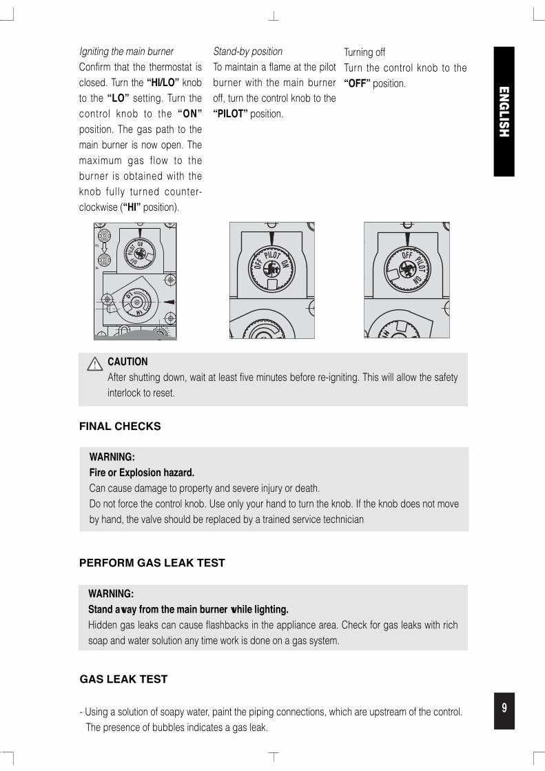
Igniting the main burnerConfirm that the thermostat isclosed. Turn the “HI/LO” knobto the “LO” setting. Turn thecontrol knob to the “ON”position. The gas path to themain burner is now open. Themaximum gas flow to theburner is obtained with theknob fully turned counter-clockwise (“HI” position).
WARNING:Stand away from the main burner while lighting.Hidden gas leaks can cause flashbacks in the appliance area. Check for gas leaks with richsoap and water solution any time work is done on a gas system.
PERFORM GAS LEAK TEST
GAS LEAK TEST
- Using a solution of soapy water, paint the piping connections, which are upstream of the control.The presence of bubbles indicates a gas leak.
CAUTIONAfter shutting down, wait at least five minutes before re-igniting. This will allow the safetyinterlock to reset.
WARNING:Fire or Explosion hazard.Can cause damage to property and severe injury or death.Do not force the control knob. Use only your hand to turn the knob. If the knob does not moveby hand, the valve should be replaced by a trained service technician
FINAL CHECKS
AE
PI L O
T
OFFPIL
OTON
OFF PILOT ON
OFF PILOTON
Stand-by positionTo maintain a flame at the pilotburner with the main burneroff, turn the control knob to the“PILOT” position.
Turning offTurn the control knob to the“OFF” position. EN
GLISH

10
ENG
LISH
- If a leak is detected, tighten the pipe connections and repeat leak test.- Light the main burner.- With the main burner in operation, paint all piping connections from the valve with a soap and
water solution. - If another leak is detected, tighten the connection.- If after tightening the connections the leak is still present, replace the leaky part or valve. Shut off
the main gas supply before attempting replacement of parts or the valve.- Using the soap and water solution, test the pressure test ports to verify that no leak is present.- If a leak is detected, tighten the screw and retest.- If after tightening the pressure test port screw and the leak is still present, shut off main gas
supply, then replace the valve.
SHUTDOWN PERFORMANCE TEST
WARNING:Fire or Explosion Hazard.Can cause severe injury or death.Perform the safety shutdown check any time work is done on a gas system.
1. Place appliance in operation with the pilot and main burners lit.2. Place gas control knob in “PILOT” position. Main burner should extinguish and pilot should
remain lit.3. Extinguish pilot flame. Pilot gas safety shutoff proves complete shutdown due to the fact the
safety shutoff valve prohibits main burner and pilot gas flow.4. Wait at least five minutes for the safety magnet to reset and residual gas to clear from the
combustion chamber.5. Relight pilot burner and operate the system through one complete cycle to ensure all functions
operate correctly.
PILOT
PILOT
0FF
0N
Fig. A
VALVE CONVERSION
- Turn control knob to the “OFF” position, and shut off the gas supply to the valve.
- Using a Torx T20 or Slotted screwdriver, remove anddiscard the three regulator assembly mounting screws, pressure diaphragm and the spring anddiaphragm assembly. (fig. A)
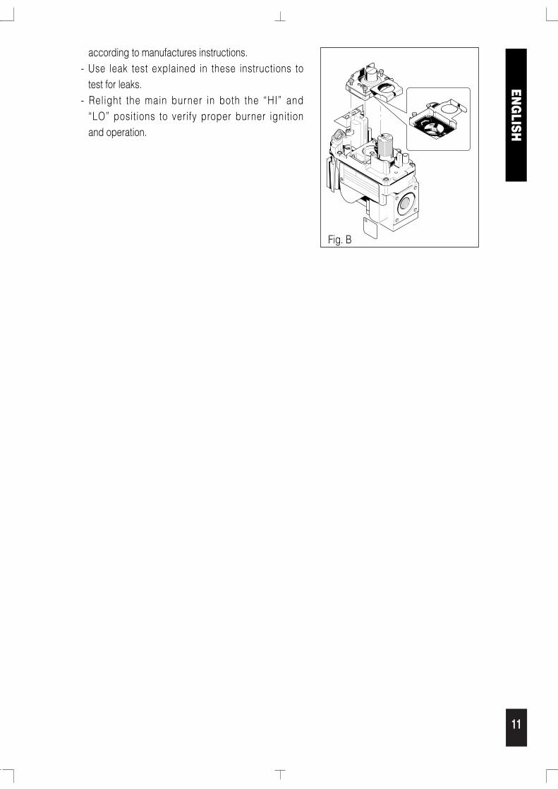
- Insure that the rubber gasket is present and properly positioned, then install the new regulator assembly tothe valve using the new screws supplied with the kit(fig. B) Tighten screws securely to 25 in/lbs torque.
- Install the enclosed identif ication label to thevalve body where it can be easily seen. (fig. B)
- Apply gas to system and re-l ight appliance
VALVE CONVERSION WITH CONVERSION KIT
11
PILOT
PILOT
0FF
0N
Fig. B
according to manufactures instructions.- Use leak test explained in these instructions to
test for leaks.- Relight the main burner in both the “HI” and
“LO” positions to verify proper burner ignitionand operation.
ENG
LISH
12
ENG
LISH
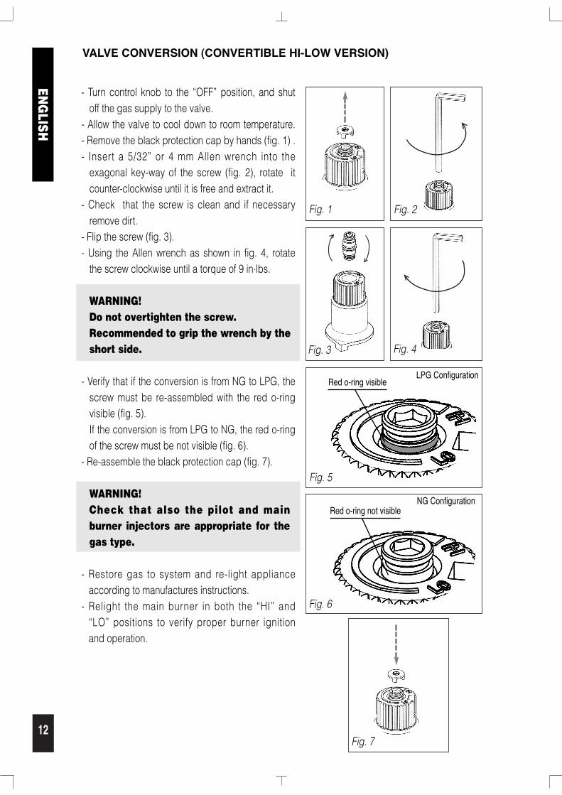
VALVE CONVERSION (CONVERTIBLE HI-LOW VERSION)
- Turn control knob to the “OFF” position, and shutoff the gas supply to the valve.
- Allow the valve to cool down to room temperature.- Remove the black protection cap by hands (fig. 1) .- Insert a 5/32” or 4 mm Allen wrench into the
exagonal key-way of the screw (fig. 2), rotate itcounter-clockwise until it is free and extract it.
- Check that the screw is clean and if necessaryremove dirt.
- Flip the screw (fig. 3).- Using the Allen wrench as shown in fig. 4, rotate
the screw clockwise until a torque of 9 in.lbs.
WARNING! Do not overtighten the screw.Recommended to grip the wrench by theshort side.
- Verify that if the conversion is from NG to LPG, thescrew must be re-assembled with the red o-ringvisible (fig. 5). If the conversion is from LPG to NG, the red o-ringof the screw must be not visible (fig. 6).
- Re-assemble the black protection cap (fig. 7).
WARNING! Check that also the pilot and mainburner injectors are appropriate for thegas type.
- Restore gas to system and re-light applianceaccording to manufactures instructions.
- Relight the main burner in both the “HI” and“LO” positions to verify proper burner ignitionand operation.
Fig. 1
Fig. 5
Fig. 6
Red o-ring visibleLPG Configuration
Fig. 2
Red o-ring not visibleNG Configuration
Fig. 3
Fig. 7
Fig. 4
13
Maintenance
This valve is not field serviceable. There are no replaceable parts. Do notdisassemble, or attempt replacement of any parts on or in the valve.Improper adjustment or tampering with settings can result in severeinjury or death.
If the main burner does not ignite when called for…
1. Confirm that the gas control knob is in the “ON” position.2. Adjust the thermostat several degrees above ambient temperature.3. Use a DC voltmeter to measure the voltage across the TPTH and TP terminals. Main operator
voltage: Open circuit ≥ 325mV Closed circuit ≥ 100mV4. If voltage is not present, check the control circuit for proper operation.5. If proper control system voltage is present, replace the gas control.
ACCESSORIES
Millivolt generator 450mm (19”) 0.240.001Millivolt generator 600mm (23”) 0.240.002Piezo-igniter 0.073.953Bracket for piezo-igniter 0.978.099Bracket mounting screw 0.953.303Battery powered igniter 0.073.801Battery igniter switch and cable 0.927.017Control knob extension 0.916.188Adjustment knob extension 0.916.189Many other accessories available on request
ENG
LISH

14

15

SIT Group