Embed Size (px)
Citation preview
OmniSTAR 8200HP
User Manual
Issue 1.07, October 2008

OmniSTAR 8200HP User Manual
Issue 1.07, 10/2008
ii
Notice to Customers
This manual has been produced to ensure the very best performance from your OmniSTAR receiver. The manual has been clearly set out with simple instructions to ensure trouble free usage of your OmniSTAR receiver. This publication could contain technical inaccuracies or typographical errors. Changes are periodically made to the information herein; these changes will be incorporated in new editions of the manual. Should you require further assistance please contact your local dealer or the OmniSTAR office.
OmniSTAR Customer Support and 24 Hour Help Line The Netherlands: OmniSTAR B.V. Dillenburgsingel 69 2263 HW Leidschendam The Netherlands Tel: +31 70 317 09 00 Fax: +31 70 317 0919 Web : www.omnistar.nlE-Mail: [email protected]
Australia: South Africa: OmniSTAR Pty Ltd OmniSTAR Pty Ltd Tel: +61 8 9322 5295 Tel: +27 11 315 0420 Fax: +61 8 9322 4164 Fax: + 27 11 312 1774 Web : www.omnistar.com.au Web : www.omnistar.co.zaE-Mail: [email protected] E-Mail: [email protected]
Singapore: USA: Fugro OmniSTAR Pte Ltd OmniSTAR Inc. Tel: +65 6542 5001 Tel: +1 713 785 5850 Fax: +65 6542 2208 Fax: +1 713 785 5164 E-Mail: [email protected] Web: www.omnistar.com
E-Mail: [email protected]
OmniSTAR 8200HP User Manual
Issue 1.07, 10/2008
iii
One-Year Limited Hardware Warranty
OmniSTAR B.V and its operating companies world-wide (OmniSTAR), warrants this product to be free from defects in workmanship and material for a period of one year from the date of original sale by OmniSTAR or its authorised dealers, to the original purchaser or end user.
OmniSTAR reserves the right to repair and/or replace, at its option, any part or parts found to be defective, provided such defects, in their opinion, are due to faulty material or workmanship and are not caused by unauthorised or improper repair or abuse, or normal wear. Purchaser shall be responsible for shipping and insurance of the returned product for repair under this warranty. OmniSTAR will pay shipping and insurance for the product's return to purchaser provided that the product returned proves to be defective under this limited warranty.
This warranty applies only to normal usage of the product. It does not apply to units or electronic circuit boards defective due to improper installation or handling. Physical damage due to lightning or other electrical discharge and units subjected to fresh or salt-water contamination are not covered. OmniSTAR reserves the right not to warrant the product if, upon request, sufficient proof of recommended installation compliance as laid out in this manual is not provided. No other warranties are expressed or implied. No other warranties exist.
OmniSTAR assumes no responsibility for any consequential or incidental losses or damages of any nature with respect to the use of this product.
REVISION HISTORY Issue 1.0 August 2006 First release Issue 1.02 August 2006 Small textual changes, firmware
upgrade procedure added. Issue 1.03 September 2006 Sales e-mail OSSA changed
GPS status indication in GGA/RMC NMEA messages clarified.
Issue 1.04 December 2006 CAN / NMEA2000 messages clarified Description of lock display screen revised.
Issue 1.05 April 2007 NMEA digits changed to 8 Issue 1.06 May 2007 DB9 pin layout added Issue 1.07 October 2008 Modifications to pin layout
Manual Reference: OmniSTAR 8200HP User Manual Copyright OmniSTAR B.V. 2007. No part of this manual can be reproduced without the express permission of OmniSTAR B.V.
OmniSTAR 8200HP User Manual
Issue 1.07, 10/2008
iv
TABLE OF CONTENTS
INTRODUCTION ............................................................................................. 2 ABOUT THIS MANUAL ..................................................................................... 2 SYSTEM FEATURES........................................................................................ 2 RECEIVER FEATURES ..................................................................................... 3
Housing .................................................................................................... 3 Accessories.............................................................................................. 4
INSTALLATION AND SET UP ........................................................................ 6 INSTALLATION CONSIDERATIONS ..................................................................... 6 COUNTER ELECTROMAGNETIC FORCE (CEMF) ................................................ 7 CABLE INSTALLATION ..................................................................................... 8 FEATURES AND INFORMATION ......................................................................... 9
Strobes..................................................................................................... 9 Receiver status......................................................................................... 9
MOUNTING THE RECEIVER............................................................................... 9 ANTENNA LOCATION..................................................................................... 10 POWER SUPPLY REQUIREMENTS .................................................................. 10
OPERATING CONSIDERATIONS................................................................. 11 NUMBER OF VISIBLE SATELLITES.................................................................... 11 MULTIPATH.................................................................................................. 11 POSITION DILUTION OF PRECISION (PDOP) ................................................... 12 SATELLITE ELEVATIONS ................................................................................ 12 OMNISTAR CORRECTIONS ........................................................................... 12 INTERFERENCE ............................................................................................ 12
OPERATION ................................................................................................. 13 GETTING STARTED....................................................................................... 13 COMMUNICATING WITH THE RECEIVER........................................................... 13 STARTING THE RECEIVER ............................................................................. 13 THE RECEIVER HOME SCREEN ...................................................................... 14 THE 8200HP MENU STRUCTURE ................................................................... 16
Top-level: home...................................................................................... 17 Top-level: Status .................................................................................... 17 Top-level: Configuration.......................................................................... 17 Sub-menu: Display Options .................................................................... 17 Sub-menu: GPS Status .......................................................................... 22 Sub-menu: DGPS Status........................................................................ 23 Sub-menu: Receiver Status.................................................................... 30 Sub-menu: CAN Status .......................................................................... 36 Sub-menu: GPS Config .......................................................................... 37 Sub-menu: DGPS Config........................................................................ 40 Sub-menu: Port A Config........................................................................ 44 Sub-menu: Port B Config........................................................................ 49 Sub-menu: Port C Config........................................................................ 50 Sub-menu: CAN A Config....................................................................... 50
APPENDIX A................................................................................................. 55
OmniSTAR 8200HP User Manual
Issue 1.07, 10/2008
v
TECHNICAL SPECIFICATIONS......................................................................... 55 Performance........................................................................................... 55 Environmental ........................................................................................ 55 Power requirements ............................................................................... 56 RF input / LNA power output................................................................... 56 Input / output data interface.................................................................... 56 Input / output connectors ........................................................................ 56 Physical dimensions............................................................................... 56
APPENDIX B................................................................................................. 58 NMEA 0183 MESSAGE OPTIONS .................................................................. 58 NMEA 0183 MESSAGE FORMATS ................................................................. 59
GGA – GPS Fix Data ........................................................................ 59 GLL - Geographic Position – Latitude/Longitude .............................. 60 GRS – GPS Range Residuals........................................................... 60 GSA – GPS DOP and Active Satellites ............................................. 61 GST – GPS Pseudorange Noise Statistics ....................................... 62 GSV – GPS Satellites in View........................................................... 63 MSS – Beacon Receiver Signal Status ............................................. 64 PTNLSM – Proprietary (RTCM Special)............................................ 64 PTNLEV – Proprietary (Event Marker).............................................. 65 PTNLID – Proprietary (Receiver ID) ................................................ 65 PTNLDG – Proprietary (DGPS Receiver Status)............................... 66 PTNL,GGK – Time, Position, Position Type, DOP ............................. 67 RMC – Recommended Minimum Specific GPS Data..................... 68 VTG – Course Over Ground and Ground Speed............................... 69 ZDA – Time and Date....................................................................... 70
APPENDIX C................................................................................................. 71 ACRONYMS USED IN THIS MANUAL ................................................................. 71
APPENDIX D................................................................................................. 72 UPDATING THE 8200HP FIRMWARE............................................................... 72
APPENDIX E................................................................................................. 78 OMNISTAR REFERENCE STATIONS................................................................ 78
APPENDIX F................................................................................................. 79 RECEIVER SERVICE PROCEDURE .................................................................. 79
APPENDIX G ................................................................................................ 80 OMNISTAR RECEIVER PROBLEM REPORT FORM ........................................... 80
USER NOTES ............................................................................................... 81
LIST OF FIGURES Figure 1: 8200HP Back End ............................................................................ 4 Figure 2: Z+ antenna ....................................................................................... 5
OmniSTAR 8200HP User Manual
Issue 1.07, 10/2008
vi
Figure 3: Zener Diode Connected.................................................................... 7 Figure 4: Multipath......................................................................................... 11 Figure 5: Home screen when OmniSTAR HP corrections are received ......... 14 Figure 6: Status screen ................................................................................. 17 Figure 7: Configuration screen....................................................................... 17 Figure 8: Contrast screen .............................................................................. 18 Figure 9: User level screen............................................................................ 18 Figure 10: Lock Display screen...................................................................... 18 Figure 11: Lock Display - Enter Password screen.......................................... 19 Figure 12: Language screen.......................................................................... 19 Figure 13: Units screen ................................................................................. 19 Figure 14: SNR Units screen ......................................................................... 20 Figure 15: Clear BB RAM screen................................................................... 21 Figure 16: Update Receiver screen ............................................................... 21 Figure 17: Update Receiver - Enter Password screen ................................... 21 Figure 18: GPS Lat/Long screen ................................................................... 22 Figure 19: GPS Altitude screen ..................................................................... 22 Figure 20: GPS Speed and Heading screen .................................................. 22 Figure 21: GPS Channel Status screen......................................................... 23 Figure 22: GPS DOP values screen .............................................................. 23 Figure 23: DGPS Sat Tracking screen........................................................... 24 Figure 24: Service ID screen ......................................................................... 24 Figure 25: DGPS Data Source screen........................................................... 24 Figure 26: Age of DGPS/Sync screen ........................................................... 25 Figure 27: VBS Info screen: User Code......................................................... 25 Figure 28: VBS Info screen: User Enabled .................................................... 25 Figure 29: VBS Info screen: Stop .................................................................. 26 Figure 30: VBS Info screen: Received Data .................................................. 26 Figure 31: VBS Info screen: VBS Service Level ............................................ 26 Figure 32: VBS Info screen: VBS version ...................................................... 26 Figure 33: VBS Info screen: Figure of merit................................................... 27 Figure 34: HP/XP Info screen: User Code ..................................................... 27 Figure 35: HP/XP Info screen: Initialisation.................................................... 27 Figure 36: HP/XP Info screen: Solution convergence .................................... 27 Figure 37: HP/XP Info screen: Stop............................................................... 28 Figure 38: HP/XP Info screen: Subscription type ........................................... 28 Figure 39: HP/XP Info screen: Subscription mode......................................... 28 Figure 40: HP/XP Info screen: HP version..................................................... 29 Figure 41: XP/HP Info screen: Srvc ID screen 1 ............................................ 29 Figure 42: XP/HP Info screen: Srvc ID screen 2 ............................................ 29 Figure 43: UTC time and day......................................................................... 30 Figure 44: UTC date and GPS week.............................................................. 30 Figure 45: Receiver serial number................................................................. 30 Figure 46: Receiver firmware version ............................................................ 31 Figure 47: Receiver Options: Fast Rate......................................................... 31 Figure 48: Receiver Options: Base Station .................................................... 31 Figure 49: Receiver Options: Everest Multipath Rejection ............................. 32 Figure 50: Receiver Options: Modem Control ................................................ 32 Figure 51: Receiver Options: D&E Sub.......................................................... 32 Figure 52: Receiver Options: TNL Sub .......................................................... 32 Figure 53: Receiver Options: Carrier Phase .................................................. 32
OmniSTAR 8200HP User Manual
Issue 1.07, 10/2008
vii
Figure 54: Receiver Options: VRS Processing .............................................. 33 Figure 55: Receiver Options: Tilt Sensor ....................................................... 33 Figure 56: Position error caused by a tilted, high-mounted receiver antenna . 33 Figure 57: Receiver Options: WAAS.............................................................. 34 Figure 58: Receiver Options: CMR Input ....................................................... 34 Figure 59: Receiver Options: Point/Line/Area ................................................ 34 Figure 60: Receiver Options: CAN Bus.......................................................... 34 Figure 61: System voltages ........................................................................... 35 Figure 62: System temperature ..................................................................... 35 Figure 63: Incident code ................................................................................ 35 Figure 64: J1939 Address Claim Channel A .................................................. 36 Figure 65: J1939 Address Claim Channel B .................................................. 36 Figure 66: Channel A TPCAN Connections ................................................... 36 Figure 67: Channel B TPCAN Connections ................................................... 37 Figure 68: Restore GPS Defaults .................................................................. 37 Figure 69: GPS Mode.................................................................................... 37 Figure 70: System Masks .............................................................................. 38 Figure 71: PDOP Settings ............................................................................. 38 Figure 72: Position Filter................................................................................ 39 Figure 73: Carrier Code Filter ........................................................................ 39 Figure 74: Position Rate ................................................................................ 39 Figure 75: Dynamic Mode.............................................................................. 40 Figure 76: GPS Diagnostics .......................................................................... 40 Figure 77: DGPS Source Select .................................................................... 40 Figure 78: DGPS Backup Source Select ....................................................... 41 Figure 79: DGPS Correction Age................................................................... 41 Figure 80: EZ Sat .......................................................................................... 42 Figure 81: Satellite frequency ........................................................................ 42 Figure 82: Satellite baudrate.......................................................................... 42 Figure 83: HP/XP Autoseed........................................................................... 43 Figure 84: HP/XP Init mode ........................................................................... 43 Figure 85: HP/XP Convergence limit ............................................................. 44 Figure 86: OmniSTAR HP/XP Debug Information screen .............................. 44 Figure 87: Port A I/O configuration settings ................................................... 44 Figure 88: Port-A Modem control options ...................................................... 46 Figure 89: NMEA messages 1....................................................................... 47 Figure 90: NMEA messages 2....................................................................... 48 Figure 91: NMEA messages 3....................................................................... 48 Figure 92: NMEA/TSIP output rates .............................................................. 48 Figure 93: 1Hz NMEA message output.......................................................... 49 Figure 94: NMEA Quality configuration.......................................................... 49 Figure 95: Port B I/O configuration settings ................................................... 50 Figure 96: Port C Out screen......................................................................... 50 Figure 97: CAN-bus baudrate setting............................................................. 51 Figure 98: CAN-bus address setting.............................................................. 51 Figure 99: CAN-bus messages...................................................................... 51 Figure 100: CAN-bus message rates............................................................. 52 Figure 101: NMEA 2000 messages 1 ............................................................ 52 Figure 102: NMEA 2000 messages 2 ............................................................ 52 Figure 103: NMEA 2000 message rates ........................................................ 53 Figure 104: TPCAN protos ............................................................................ 53
OmniSTAR 8200HP User Manual
Issue 1.07, 10/2008
viii
Figure 105: CAN-bus self-configured address ............................................... 54 Figure 106: Pin layout (receiver connector) ................................................... 57 Figure 107: Flashloader main screen............................................................. 72 Figure 108: Firmware image selection screen ............................................... 73 Figure 109: Establishing communication with the receiver............................. 73 Figure 110: Receiver selection screen........................................................... 74 Figure 111: Uploading firmware screen ......................................................... 75 Figure 112: Erasing program space screen ................................................... 75 Figure 113: Programming new firmware screen............................................. 76 Figure 114: Flashing completed successfully ................................................ 76
LIST OF TABLES Table 1: 8200HP Interfaces ............................................................................. 4 Table 2: Position types .................................................................................. 15 Table 3: Differential information..................................................................... 16 Table 4: XP/HP Subscription types................................................................ 29 Table 5: 8200HP input protocols.................................................................... 45 Table 6: 8200HP output protocols ................................................................. 46 Table 7: (D)GPS quality indicators................................................................. 49 Table 8: NMEA 2000 default message rates ................................................. 53 Table 9: 8200HP Power/data Port Pin-Out Descriptions (both port A and B) . 57 Table 10: NMEA 0183 messages available for the 8200HP........................... 58 Table 11: Description of the GGA message................................................... 59 Table 12: Description of the GLL message.................................................... 60 Table 13: Description of the GRS message................................................... 60 Table 14: Description of the GSA message. .................................................. 61 Table 15: Description of the GST message. .................................................. 62 Table 16: Description of the GSV message. .................................................. 63 Table 17: Description of the MSS message................................................... 64 Table 18: Description of the PTNLSM message. ........................................... 64 Table 19: Description of the PTNLEV message............................................. 65 Table 20: Description of the PTNLID message. ............................................. 65 Table 21: Description of the PTNLDG message. ........................................... 66 Table 22: Description of the PTNL,GGK message......................................... 67 Table 23: Description of the RMC message. ................................................. 68 Table 24: Description of the VTG message. .................................................. 69 Table 25: Description of the ZDA message. .................................................. 70
OmniSTAR 8200HP User Manual
Issue 1.07, 10/2008
2
Introduction
About This Manual This manual has been produced to assist the typical user with the installation and operation of the OmniSTAR 8200HP DGPS Receiver.
System Features The OmniSTAR 8200HP DGPS Receiver is part of the OmniSTAR world-wide DGPS Service. The OmniSTAR service is a full-time differential GPS (DGPS) broadcast system delivering corrections from an array of GPS reference stations located around the globe. Reference stations provide industry standard formatted corrections to Network Control Centres (NCC’s) at strategic geographic locations, where the corrections are decoded, checked, and repackaged in a highly efficient format for broadcast. The data is modulated onto an RF carrier that is then up-converted for transmission to an L-band communications satellite. The signals are received at the user's location by an antenna, demodulated by a receiver, and are made available, after selection of the desired individual reference site's data set, as corrections for use in a GPS, differential-capable, receiver. The OmniSTAR 8200HP series of receivers support the following OmniSTAR®
services: HP, this is the High Performance service where dual frequency GPS carrier phase measurements are used in an intelligent and innovative way to create wide area positioning results of unmatched accuracy and performance. XP, this is the Extended Position service where precise orbit and clock data is used to determine the position worldwide without using any reference stations.
VBS, this is the Virtual Base Station service where single frequency GPS code phase measurements are used to create RTCM corrections data optimised for the users current position.
OmniSTAR 8200HP User Manual
Issue 1.07, 10/2008
3
Receiver Features The OmniSTAR 8200HP receiver has the following features:
• 12 parallel GPS code/carrier tracking channels (L1 C/A-code and carrier, L2 carrier only)
• LCD front panel display • Receiver configuration using the front panel • Submeter differential accuracy (RMS), assuming at least five
satellites and a PDOP (Position Dilution of Precision) of less than four (OmniSTAR VBS)
• Decimeter differential accuracy (OmniSTAR HP/XP) • Low power consumption • 1, 5, 10 Hz position output data (user selectable) • Voltage and temperature monitoring and reporting • A rugged, environmentally-sealed enclosure • Everest multipath rejection technology • Two combined power/data ports with Deutsch-brand connectors,
supporting the following protocols: CAN 2.0B:
J1939 and NMEA 2000 messages (ISO 11783 compliant, supporting some ISO 11783 messages)
RS-232: NMEA-0183 output, RTCM SC-104 input and output, TSIP binary standard input and output protocol, ASCII input, CMR input (if enabled)
1 PPS (Pulse per second) strobe signal to enable an external instrument to synchronize its internal time with a time derived from the very accurate GPS system time.
• GPS antenna port
Housing The 8200HP is housed in an enclosure to provide a complete receiver solution. When connected to an antenna and a power source, the 8200HP is a fully functioning GPS/VBS/XP/HP receiver. The enclosure offers protection against environmental conditions and RF interference. In addition, it provides an easy-to-use interface to the data, power and status signals of the GPS card and a rugged, water, shock and vibration resistant housing for outdoor applications.
OmniSTAR 8200HP User Manual
Issue 1.07, 10/2008
4
Accessories The following accessories are included with the 8200HP:
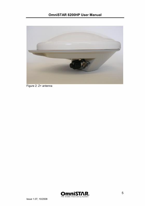
• 1 right angle combined power/data cable • 1 GPS antenna type Z Plus • 1 antenna cable (5 meters) • 1 magnetic antenna mount • A CD containing PC utilities and product documentation
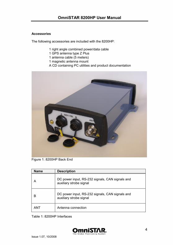
Figure 1: 8200HP Back End
Name Description
A DC power input, RS-232 signals, CAN signals and auxiliary strobe signal
B DC power input, RS-232 signals, CAN signals and auxiliary strobe signal
ANT Antenna connection
Table 1: 8200HP Interfaces
OmniSTAR 8200HP User Manual
Issue 1.07, 10/2008
5
Figure 2: Z+ antenna
OmniSTAR 8200HP User Manual
Issue 1.07, 10/2008
6
Installation and Set Up
Installation Considerations Before commencing installation of the OmniSTAR 8200HP in a vehicle or aircraft, the following should be considered:
• Determine the preferred location for each unit. Consider cable length, connector attachment space (cable bend radius), stowing excess cable, moisture, chemical corrosion, vibration and heat exposure.
• Before drilling holes, consider using existing hardware and locations where equipment was previously installed. Avoid drilling holes that may damage other equipment (e.g. structural frame members, electrical cables or fluid lines).
• High vibration and high temperature locations should be avoided whenever possible.
• In application where vibration exceeds 5Gs acceleration, shock mounts are required. (Refer to Customer support for mounting recommendations).
• Vehicle primary power has voltages that may be harmful to personnel and equipment. Disconnect the battery cable from the battery –Ve (negative) terminal before making connection to any power terminal within the vehicle.
OmniSTAR 8200HP User Manual
Issue 1.07, 10/2008
7
Counter Electromagnetic Force (CEMF) A potential problem inherent in any installation of electronic systems within a vehicle is Counter Electro-magnetic Force (CEMF). CEMF is caused when relays or solenoids, connected to the vehicle DC power distribution, are de-energised. The voltage produced may exceed – 400 volts. CEMF is produced by equipment such as the following:
• Electric fan brakes
• Air conditioners
• Starter relays
• Electric pump relays
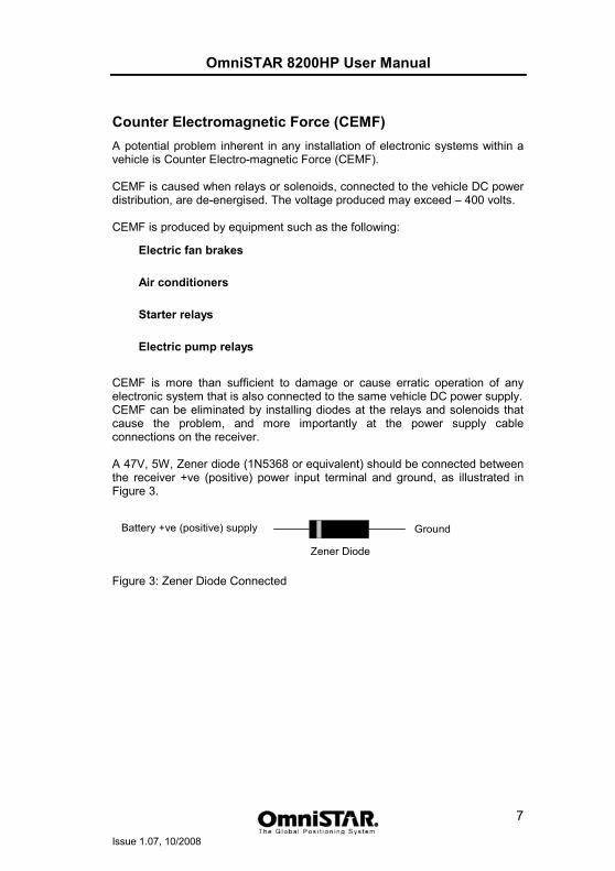
CEMF is more than sufficient to damage or cause erratic operation of any electronic system that is also connected to the same vehicle DC power supply. CEMF can be eliminated by installing diodes at the relays and solenoids that cause the problem, and more importantly at the power supply cable connections on the receiver. A 47V, 5W, Zener diode (1N5368 or equivalent) should be connected between the receiver +ve (positive) power input terminal and ground, as illustrated in Figure 3.
Figure 3: Zener Diode Connected
GroundBattery +ve (positive) supply
Zener Diode
OmniSTAR 8200HP User Manual
Issue 1.07, 10/2008
8
Cable Installation Cables must be correctly installed for optimum system operation. Therefore, the following should be noted:
• Do not route an L-Band receiver remote antenna cable with the cabling of any other radio system. This may cause interference between both systems.
• If at all possible, do not run L-Band receiver antenna cables parallel to other radio system cabling closer than 30 centimetres.
• If cables must cross, ensure that they cross at an angle of 90°. This minimises the possibility of interference.
• As far as is practicable, ensure that cables and I/O connectors are unique and fit only in their allocated location.
• Avoid routing cables along-side power generator cabling and other high electrical noise sources. This can cause interference.
• Do not kink cables or force cables into sharp bends that may damage the cables and cause system failure.
• After installation, ensure that excess cable is looped and clamped or tied safely away from any control cables, fuel lines, hydraulic lines or moving parts.
• When stowing over length cabling, form loops not less than 150 mm minimum cable bend radius.
• Cable routing must avoid high temperature exposure (e.g. exhaust manifold).
OmniSTAR 8200HP User Manual
Issue 1.07, 10/2008
9
Features and Information This section contains information on the features of the 8200HP receiver.
Strobes On the 8200HP, a set of outputs that provide status and synchronisation signals are given. These signals are called strobes. Access to the 8200HP strobe signals can be obtained through both data ports. The strobe available on the 8200HP is the One Pulse Per Second (1 PPS) signal. The falling edge of this signal is synchronised with GPS time.
Receiver status The 8200HP is equipped with an LCD display showing the status of the receiver. Using the display and the buttons around the display, the receiver can be configured without the need to connect a computer. The functions of the LCD display and the configuration menus are described further on in this manual.
Mounting the receiver The 8200HP casing is equipped with four slotted mounting holes to facilitate mounting the receiver to a surface. This section provides information on how to mount the receiver. Note: The receiver casing was not designed for mounting in high-dynamics or high-vibration environments. To mount the 8200HP receiver:
1. Using the slotted holes as a template, drill four holes in the mounting surface.
2. Use screws to secure the casing to the mounting surface. When using machine screws, tap the mounting holes to fasten the receiver to the mounting surface. Alternatively, self-tapping screws can be used.
3. Make sure not to mount the receiver in a location where it can easily be damaged during normal operation. Try to protect the receiver against harsh environmental conditions.
OmniSTAR 8200HP User Manual
Issue 1.07, 10/2008
10
Antenna Location Antenna positioning is critical to system performance. The following conditions must be met for optimum system performance:
1. Antenna must be mounted at least 1.5 metres away from transmitting antennas of any frequency. Closer positioning may cause overloading of receiver RF circuits.
2. The antenna should be mounted at the highest practical point that will give a good view of the horizon and be as near level as possible.
3. The antenna must be located along the vehicle centre-line, or at a relevant reference point on the vehicle.
4. The antenna should not be mounted in a location where it can easily be damaged during normal operation.
Power Supply Requirements The 8200HP can be powered by a vehicle or by a customer-supplied power source of 10-32 VDC, capable of delivering at least 5W continuous output power. For continued protection against the risk of fire, the power lead to the 8200HP receiver should be provided with a 10 A (maximum) fuse.
Warning: Before powering the receiver, make sure the antenna cable and antenna are connected and the power/data cable is connected and secured. Connecting or disconnecting an antenna or antenna cable when the receiver is already powered may permanently damage the receiver’s antenna port or the antenna itself, voiding your warranty. Connecting or disconnecting the power/data cable to/from the receiver when the cable is already powered may result in increased wear or an early failure of the power/data connector.
Warning: If the voltage supplied is below the minimum specification, the receiver will suspend operation. If the voltage supplied is above the maximum specification, the receiver may be permanently damaged, voiding your warranty.
OmniSTAR 8200HP User Manual
Issue 1.07, 10/2008
11
Operating considerations The 8200HP has proven to be a high-quality positioning device. The accuracy that the user can obtain depends on several factors, including: • Number of visible satellites • Multipath • Dilution of Precision (DOP) • Satellite elevations • OmniSTAR corrections
Number of visible satellites A minimum of four satellites is required to calculate a 3-dimensional position. In general it can be said that every increase in the number of visible satellites will result in an increase in the systems’ accuracy. As the GPS satellites orbit the earth the number of visible satellites will change in time. The GPS constellation has been designed to provide a minimum of 4 visible satellites at any location at all times. The number of visible satellites can decrease due to blockage by objects such as trees and buildings.
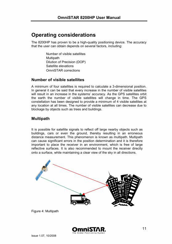
Multipath
It is possible for satellite signals to reflect off large nearby objects such as buildings, cars or even the ground, thereby resulting in an erroneous distance measurement. This phenomenon is known as multipath. Multipath can cause significant errors in the position determination and it is therefore important to place the receiver in an environment, which is free of large reflective surfaces. It is also recommended to mount the receiver directly onto a surface, while maintaining a clear view of the sky in all directions.
Figure 4: Multipath
OmniSTAR 8200HP User Manual
Issue 1.07, 10/2008
12
Position Dilution of Precision (PDOP) The Position Dilution of Precision (PDOP) is a measure of the satellite geometry. The closer to 1 the PDOP value, the more accurate the GPS position will be.
Satellite elevations The signal from a satellite that is low on the horizon will travel a greater distance through the atmosphere. This results in a lower signal strength and a delayed reception, thereby causing erroneous and noisy data. By default the 8200HP is configured to ignore any GPS satellites that have an elevation angle lower than 5° for VBS and lower than 8° for HP.
OmniSTAR corrections For accurate positioning it is essential that the differential corrections are received. In order to ensure reception of the OmniSTAR satellite signal the line of sight towards the satellite must not be blocked by objects such as trees and buildings. To find out which OmniSTAR satellite(s) can be received at your geographic position, please visit the surveyplanner website (http://www.surveyplanner.com/).
Interference Although the 8200HP has been designed to provide optimal system performance under most circumstances, due to the nature of radio communications it is possible, that the system performance degrades as a result of local interference sources. When interference levels are too high, the 8200HP may even lose lock to either the OmniSTAR satellite or the GPS satellites. Interference sources include radio and television transmitters, radars, microwave ovens, poorly shielded spark plugs and aeronautical radionavigation systems, in short: any device producing electromagnetic energy (directly or through harmonic frequencies) in the 1525 - 1580 MHz band.
OmniSTAR 8200HP User Manual
Issue 1.07, 10/2008
13
Operation Before operating the receiver for the first time, ensure that you follow the following installation instructions.
1. Mount the 8200HP receiver in a suitable place (see also page 9).
2. Mount the OmniSTAR antenna in a suitable place (see also page 10).
3. Connect the antenna cable to the antenna and the receiver, making sure the right angle connector is connected to the antenna. Secure the antenna cable using tie wraps.
4. Connect the data/power cable to port A of the 8200HP receiver. If desired, also connect the data connector (9 pin sub D connector).
5. Connect the power leads to a suitable (10-32 V DC) power supply.
Getting Started The purpose of this section is to get you started with the 8200HP as quickly as possible. The guide will address receiving the satellite data carrier, and then checking the functionality and status of the HP Process. Generally, when the receiver is supplied to you it will be configured for the mode and data link(s) you have subscribed to. In most cases getting up and running will be a case of connecting the appropriate cables and applying power to the system.
Communicating with the Receiver Communicating with the receiver is possible using the receiver’s front panel and LCD screen, the AgRemote program on a Microsoft Windows-based computer or Viewall on a PDA. The AgRemote program will communicate with the 8200HP through a standard serial port using the TSIP-protocol. AgRemote will copy the front panel interface (LCD screen and buttons) to your desktop, providing you with a familiar interface when the receiver’s front panel is hard to reach. Because the 8200HP’s display is small, the receiver uses a number of menus and submenus to access all of the receiver’s possible information and configuration screens.
Starting the Receiver The receiver’s software resides in read-only memory. As such, the unit “self-boots” when turned on and undergoes a complete self-test. When the receiver is first turned on, it will show the following boot sequence: Starting Up (followed by a progress indicator bar on the second line of
the display)
OmniSTAR 8200HP User Manual
Issue 1.07, 10/2008
14
EHES (followed by a progress indicator bar on the second line of the display)
Starting Up (followed by a progress indicator bar on the second line of the display) Launch[______GD] Launch[______HP] Launch[______CN] Launch[______Go] _____8200HP (C)1997-2003_TNL __ 8200HP __P/N_55581-301
8200HP Version:____3.57
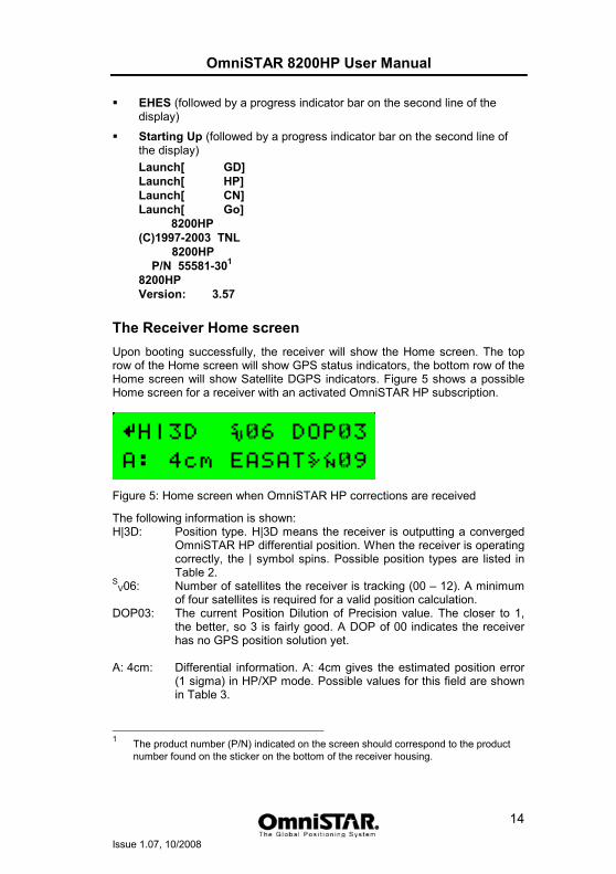
The Receiver Home screen Upon booting successfully, the receiver will show the Home screen. The top row of the Home screen will show GPS status indicators, the bottom row of the Home screen will show Satellite DGPS indicators. Figure 5 shows a possible Home screen for a receiver with an activated OmniSTAR HP subscription.
Figure 5: Home screen when OmniSTAR HP corrections are received
The following information is shown: H|3D: Position type. H|3D means the receiver is outputting a converged
OmniSTAR HP differential position. When the receiver is operating correctly, the | symbol spins. Possible position types are listed in Table 2.
SV06: Number of satellites the receiver is tracking (00 – 12). A minimum
of four satellites is required for a valid position calculation. DOP03: The current Position Dilution of Precision value. The closer to 1,
the better, so 3 is fairly good. A DOP of 00 indicates the receiver has no GPS position solution yet.
A: 4cm: Differential information. A: 4cm gives the estimated position error
(1 sigma) in HP/XP mode. Possible values for this field are shown in Table 3.
1 The product number (P/N) indicated on the screen should correspond to the product
number found on the sticker on the bottom of the receiver housing.
OmniSTAR 8200HP User Manual
Issue 1.07, 10/2008
15
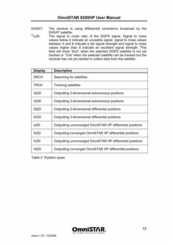
EASAT: The receiver is using differential corrections broadcast by the EASAT satellite.
S/N09: The signal to noise ratio of the DGPS signal. Signal to noise values below 4 indicate an unusable signal, signal to noise values between 4 and 8 indicate a fair signal strength and signal to noise values higher than 8 indicate an excellent signal strength. This field will show ‘Srch’ when the selected DGPS satellite is not yet tracked or ‘Trck’ when the selected satellite can be tracked but the receiver has not yet started to collect data from the satellite.
Display Description
SRCH Searching for satellites
TRCK Tracking satellites
G|2D Outputting 2-dimensional autonomous positions
G|3D Outputting 3-dimensional autonomous positions
D|2D Outputting 2-dimensional differential positions
D|3D Outputting 3-dimensional differential positions
x|3D Outputting unconverged OmniSTAR XP differential positions
X|3D Outputting converged OmniSTAR XP differential positions
h|3D Outputting unconverged OmniSTAR HP differential positions
H|3D Outputting converged OmniSTAR HP differential positions
Table 2: Position types
OmniSTAR 8200HP User Manual
Issue 1.07, 10/2008
16
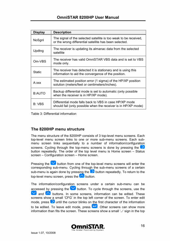
Display Description
NoSgnl The signal of the selected satellite is too weak to be received, or the wrong differential satellite has been selected.
Updtng The receiver is updating its almanac data from the selected satellite
Om-VBS The receiver has valid OmniSTAR VBS data and is set to VBS mode only.
Static The receiver has detected it is stationary and is using this information to aid the convergence of the position.
A:xxx The estimated position error (1 sigma) of the HP/XP position solution (meters/feet or centimeters/inches).
B:AUTO Backup differential mode is set to automatic (only possible when the receiver is in HP/XP mode).
B: VBS Differential mode falls back to VBS in case HP/XP mode should fail (only possible when the receiver is in HP/XP mode)
Table 3: Differential information
The 8200HP menu structure The menu structure of the 8200HP consists of 3 top-level menu screens. Each top-level menu screen links to one or more sub-menu screens. Each sub-menu screen links sequentially to a number of information/configuration screens. Cycling through the top-menu screens is done by pressing the button repeatedly. The order of the top level menu is Home screen – Status screen – Configuration screen – Home screen. Pressing the button from one of the top-level menu screens will enter the corresponding sub-menu. Cycling through the sub-menu screens of a certain sub-menu is again done by pressing the button repeatedly. To return to the top-level menu screen, press the button. The information/configuration screens under a certain sub-menu can be accessed by pressing the button. To cycle through the screens, use the
and buttons. In some screens, information can be edited. These screens show a small ‘CFG’ in the top left corner of the screen. To enter edit mode, press until the cursor blinks on the first character of the information to be edited. To leave edit mode, press . Other screens can show more information than fits the screen. These screens show a small ‘↵‘ sign in the top
OmniSTAR 8200HP User Manual
Issue 1.07, 10/2008
17
left corner. To cycle through the underlying information screens, press repeatedly. This section of the manual will describe the 8200HP’s menu structure and screens.
Top-level: home The home screen is the receiver’s default screen after a successful receiver boot. The information on the home screen has already been described in detail on the previous pages of this manual. From the home screen, the sub-menu ‘Display Options’ can be accessed.
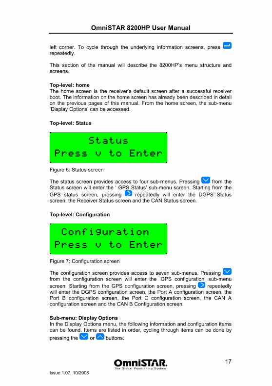
Top-level: Status
Figure 6: Status screen
The status screen provides access to four sub-menus. Pressing from the Status screen will enter the ‘ GPS Status’ sub-menu screen. Starting from the GPS status screen, pressing repeatedly will enter the DGPS Status screen, the Receiver Status screen and the CAN Status screen.
Top-level: Configuration
Figure 7: Configuration screen
The configuration screen provides access to seven sub-menus. Pressing from the configuration screen will enter the ‘GPS configuration’ sub-menu screen. Starting from the GPS configuration screen, pressing repeatedly will enter the DGPS configuration screen, the Port A configuration screen, the Port B configuration screen, the Port C configuration screen, the CAN A configuration screen and the CAN B Configuration screen.
Sub-menu: Display Options In the Display Options menu, the following information and configuration items can be found. Items are listed in order, cycling through items can be done by pressing the or buttons.
OmniSTAR 8200HP User Manual
Issue 1.07, 10/2008
18
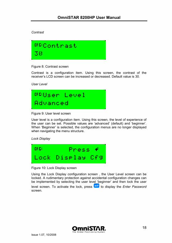
Contrast
Figure 8: Contrast screen
Contrast is a configuration item. Using this screen, the contrast of the receiver’s LCD screen can be increased or decreased. Default value is 30. User Level
Figure 9: User level screen
User level is a configuration item. Using this screen, the level of experience of the user can be set. Possible values are ‘advanced’ (default) and ‘beginner’. When ‘Beginner’ is selected, the configuration menus are no longer displayed when navigating the menu structure. Lock Display
Figure 10: Lock Display screen
Using the Lock Display configuration screen , the User Level screen can be locked. A rudimentary protection against accidental configuration changes can be implemented by selecting the user level ‘beginner’ and then lock the user level screen. To activate the lock, press to display the Enter Password screen.
OmniSTAR 8200HP User Manual
Issue 1.07, 10/2008
19
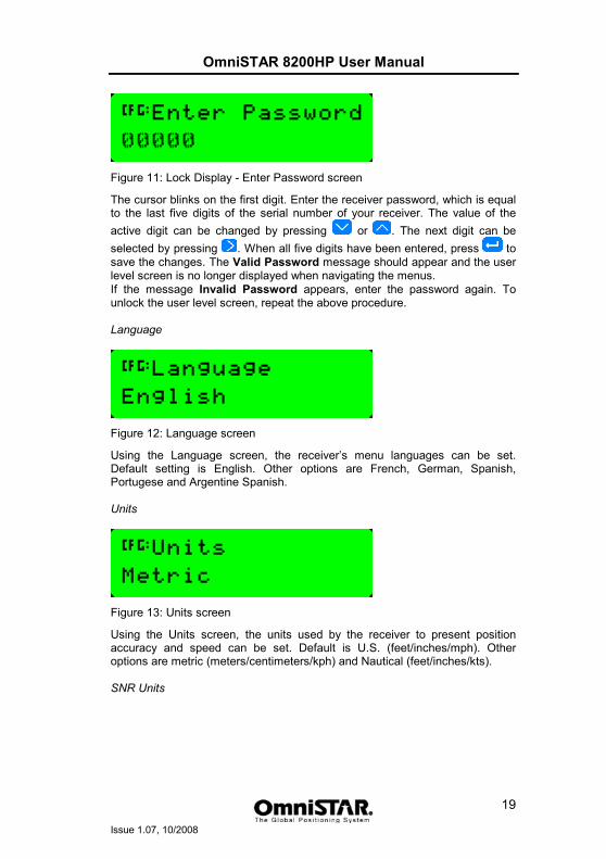
Figure 11: Lock Display - Enter Password screen
The cursor blinks on the first digit. Enter the receiver password, which is equal to the last five digits of the serial number of your receiver. The value of the active digit can be changed by pressing or . The next digit can be selected by pressing . When all five digits have been entered, press to save the changes. The Valid Password message should appear and the user level screen is no longer displayed when navigating the menus. If the message Invalid Password appears, enter the password again. To unlock the user level screen, repeat the above procedure. Language
Figure 12: Language screen
Using the Language screen, the receiver’s menu languages can be set. Default setting is English. Other options are French, German, Spanish, Portugese and Argentine Spanish. Units
Figure 13: Units screen
Using the Units screen, the units used by the receiver to present position accuracy and speed can be set. Default is U.S. (feet/inches/mph). Other options are metric (meters/centimeters/kph) and Nautical (feet/inches/kts). SNR Units
OmniSTAR 8200HP User Manual
Issue 1.07, 10/2008
20
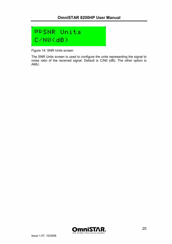
Figure 14: SNR Units screen
The SNR Units screen is used to configure the units representing the signal to noise ratio of the received signal. Default is C/N0 (dB). The other option is AMU.
OmniSTAR 8200HP User Manual
Issue 1.07, 10/2008
21
Clear BB RAM
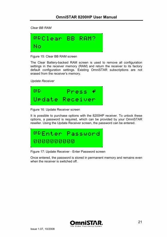
Figure 15: Clear BB RAM screen
The Clear Battery-backed RAM screen is used to remove all configuration settings in the receiver memory (RAM) and return the receiver to its factory default configuration settings. Existing OmniSTAR subscriptions are not erased from the receiver’s memory. Update Receiver
Figure 16: Update Receiver screen
It is possible to purchase options with the 8200HP receiver. To unlock these options, a password is required, which can be provided by your OmniSTAR reseller. Using the Update Receiver screen, the password can be entered.
Figure 17: Update Receiver - Enter Password screen
Once entered, the password is stored in permanent memory and remains even when the receiver is switched off.
OmniSTAR 8200HP User Manual
Issue 1.07, 10/2008
22
Sub-menu: GPS Status In the GPS Status menu, the following information items can be found. Items are listed in order, cycling through items can be done by pressing the or
buttons. Lat/Long
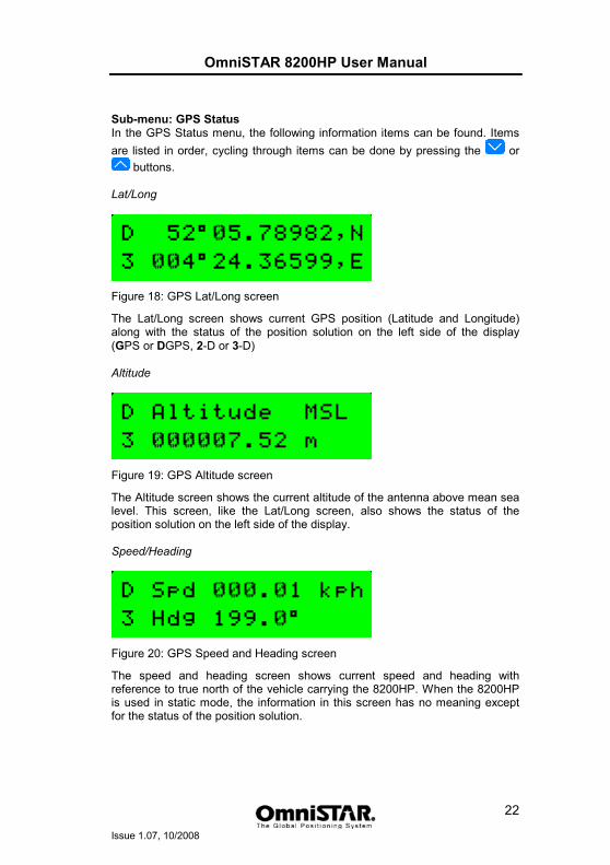
Figure 18: GPS Lat/Long screen
The Lat/Long screen shows current GPS position (Latitude and Longitude) along with the status of the position solution on the left side of the display (GPS or DGPS, 2-D or 3-D) Altitude
Figure 19: GPS Altitude screen
The Altitude screen shows the current altitude of the antenna above mean sea level. This screen, like the Lat/Long screen, also shows the status of the position solution on the left side of the display. Speed/Heading
Figure 20: GPS Speed and Heading screen
The speed and heading screen shows current speed and heading with reference to true north of the vehicle carrying the 8200HP. When the 8200HP is used in static mode, the information in this screen has no meaning except for the status of the position solution.
OmniSTAR 8200HP User Manual
Issue 1.07, 10/2008
23
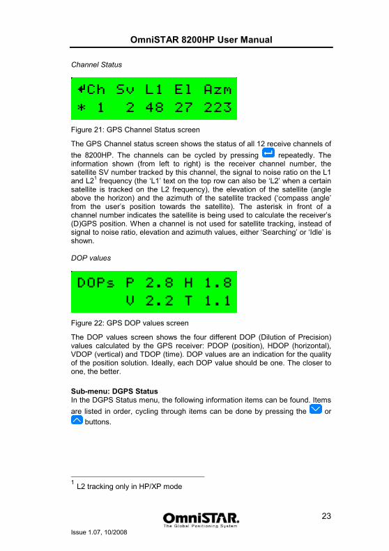
Channel Status
Figure 21: GPS Channel Status screen
The GPS Channel status screen shows the status of all 12 receive channels of the 8200HP. The channels can be cycled by pressing repeatedly. The information shown (from left to right) is the receiver channel number, the satellite SV number tracked by this channel, the signal to noise ratio on the L1 and L21 frequency (the ‘L1’ text on the top row can also be ‘L2’ when a certain satellite is tracked on the L2 frequency), the elevation of the satellite (angle above the horizon) and the azimuth of the satellite tracked (‘compass angle’ from the user’s position towards the satellite). The asterisk in front of a channel number indicates the satellite is being used to calculate the receiver’s (D)GPS position. When a channel is not used for satellite tracking, instead of signal to noise ratio, elevation and azimuth values, either ‘Searching’ or ‘Idle’ is shown. DOP values
Figure 22: GPS DOP values screen
The DOP values screen shows the four different DOP (Dilution of Precision) values calculated by the GPS receiver: PDOP (position), HDOP (horizontal), VDOP (vertical) and TDOP (time). DOP values are an indication for the quality of the position solution. Ideally, each DOP value should be one. The closer to one, the better.
Sub-menu: DGPS Status In the DGPS Status menu, the following information items can be found. Items are listed in order, cycling through items can be done by pressing the or
buttons.
1 L2 tracking only in HP/XP mode
OmniSTAR 8200HP User Manual
Issue 1.07, 10/2008
24
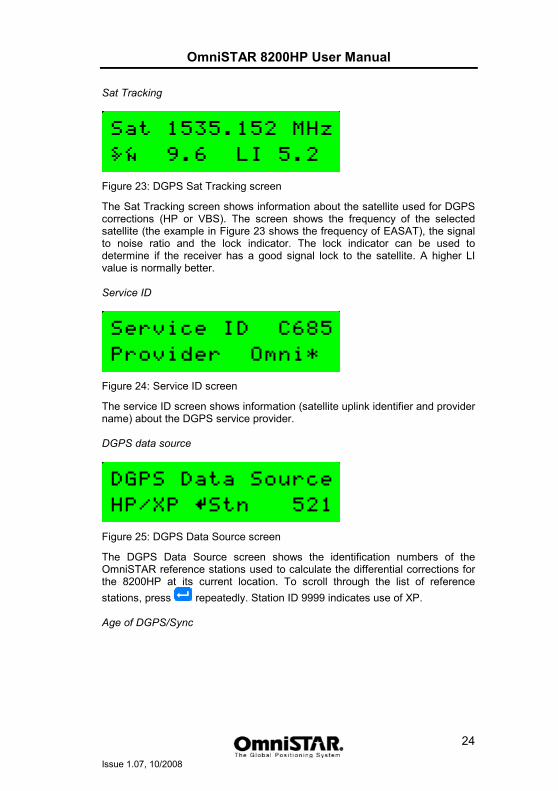
Sat Tracking
Figure 23: DGPS Sat Tracking screen
The Sat Tracking screen shows information about the satellite used for DGPS corrections (HP or VBS). The screen shows the frequency of the selected satellite (the example in Figure 23 shows the frequency of EASAT), the signal to noise ratio and the lock indicator. The lock indicator can be used to determine if the receiver has a good signal lock to the satellite. A higher LI value is normally better. Service ID
Figure 24: Service ID screen
The service ID screen shows information (satellite uplink identifier and provider name) about the DGPS service provider. DGPS data source
Figure 25: DGPS Data Source screen
The DGPS Data Source screen shows the identification numbers of the OmniSTAR reference stations used to calculate the differential corrections for the 8200HP at its current location. To scroll through the list of reference stations, press repeatedly. Station ID 9999 indicates use of XP. Age of DGPS/Sync
OmniSTAR 8200HP User Manual
Issue 1.07, 10/2008
25
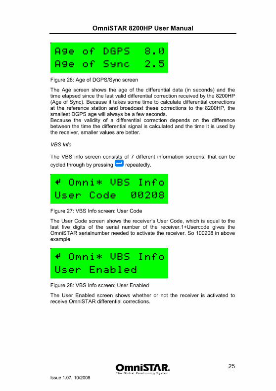
Figure 26: Age of DGPS/Sync screen
The Age screen shows the age of the differential data (in seconds) and the time elapsed since the last valid differential correction received by the 8200HP (Age of Sync). Because it takes some time to calculate differential corrections at the reference station and broadcast these corrections to the 8200HP, the smallest DGPS age will always be a few seconds. Because the validity of a differential correction depends on the difference between the time the differential signal is calculated and the time it is used by the receiver, smaller values are better. VBS Info The VBS info screen consists of 7 different information screens, that can be cycled through by pressing repeatedly.
Figure 27: VBS Info screen: User Code
The User Code screen shows the receiver’s User Code, which is equal to the last five digits of the serial number of the receiver.1+Usercode gives the OmniSTAR serialnumber needed to activate the receiver. So 100208 in above example.
Figure 28: VBS Info screen: User Enabled
The User Enabled screen shows whether or not the receiver is activated to receive OmniSTAR differential corrections.
OmniSTAR 8200HP User Manual
Issue 1.07, 10/2008
26
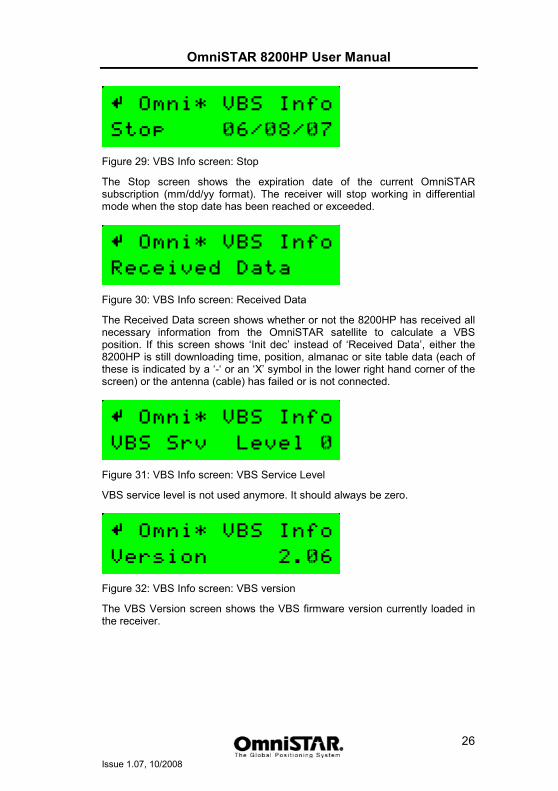
Figure 29: VBS Info screen: Stop
The Stop screen shows the expiration date of the current OmniSTAR subscription (mm/dd/yy format). The receiver will stop working in differential mode when the stop date has been reached or exceeded.
Figure 30: VBS Info screen: Received Data
The Received Data screen shows whether or not the 8200HP has received all necessary information from the OmniSTAR satellite to calculate a VBS position. If this screen shows ‘Init dec’ instead of ‘Received Data’, either the 8200HP is still downloading time, position, almanac or site table data (each of these is indicated by a ‘-‘ or an ‘X’ symbol in the lower right hand corner of the screen) or the antenna (cable) has failed or is not connected.
Figure 31: VBS Info screen: VBS Service Level
VBS service level is not used anymore. It should always be zero.
Figure 32: VBS Info screen: VBS version
The VBS Version screen shows the VBS firmware version currently loaded in the receiver.
OmniSTAR 8200HP User Manual
Issue 1.07, 10/2008
27
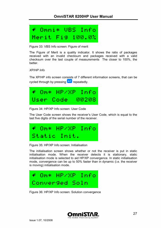
Figure 33: VBS Info screen: Figure of merit
The Figure of Merit is a quality indicator. It shows the ratio of packages received with an invalid checksum and packages received with a valid checksum over the last couple of measurements The closer to 100%, the better. XP/HP Info The XP/HP info screen consists of 7 different information screens, that can be cycled through by pressing repeatedly.
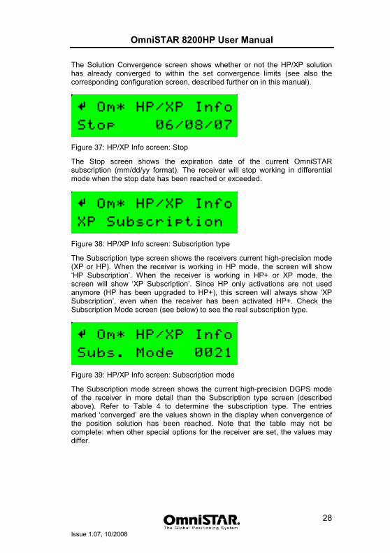
Figure 34: HP/XP Info screen: User Code
The User Code screen shows the receiver’s User Code, which is equal to the last five digits of the serial number of the receiver.
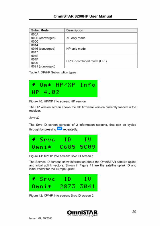
Figure 35: HP/XP Info screen: Initialisation
The initialisation screen shows whether or not the receiver is put in static initialisation mode. When the receiver detects it is stationary, static initialisation mode is selected to aid HP/XP convergence. In static initialisation mode, convergence can be up to 50% faster than in dynamic (i.e. the receiver is moving) initialisation mode.
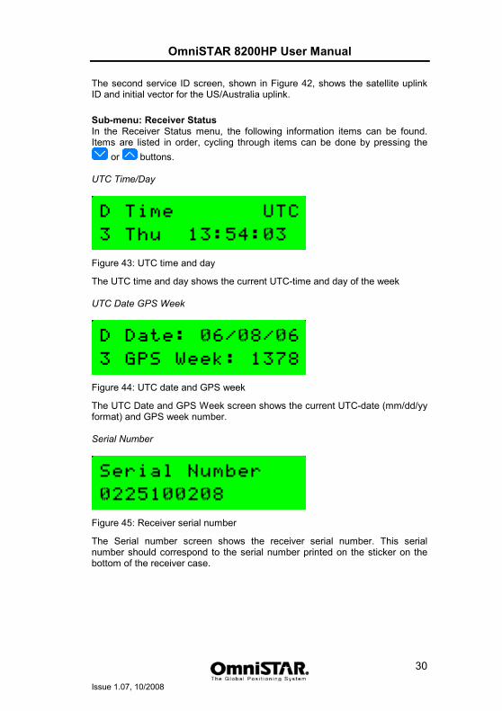
Figure 36: HP/XP Info screen: Solution convergence
OmniSTAR 8200HP User Manual
Issue 1.07, 10/2008
28
The Solution Convergence screen shows whether or not the HP/XP solution has already converged to within the set convergence limits (see also the corresponding configuration screen, described further on in this manual).
Figure 37: HP/XP Info screen: Stop
The Stop screen shows the expiration date of the current OmniSTAR subscription (mm/dd/yy format). The receiver will stop working in differential mode when the stop date has been reached or exceeded.
Figure 38: HP/XP Info screen: Subscription type
The Subscription type screen shows the receivers current high-precision mode (XP or HP). When the receiver is working in HP mode, the screen will show ‘HP Subscription’. When the receiver is working in HP+ or XP mode, the screen will show ‘XP Subscription’. Since HP only activations are not used anymore (HP has been upgraded to HP+), this screen will always show ‘XP Subscription’, even when the receiver has been activated HP+. Check the Subscription Mode screen (see below) to see the real subscription type.
Figure 39: HP/XP Info screen: Subscription mode
The Subscription mode screen shows the current high-precision DGPS mode of the receiver in more detail than the Subscription type screen (described above). Refer to Table 4 to determine the subscription type. The entries marked ‘converged’ are the values shown in the display when convergence of the position solution has been reached. Note that the table may not be complete: when other special options for the receiver are set, the values may differ.
OmniSTAR 8200HP User Manual
Issue 1.07, 10/2008
29
Subs. Mode Description 000A 000B (converged) 000C
XP only mode
0014 0016 (converged) 0017
HP only mode
001E 001F 0020 0021 (converged)
HP/XP combined mode (HP+)
Table 4: XP/HP Subscription types
Figure 40: HP/XP Info screen: HP version
The HP version screen shows the HP firmware version currently loaded in the receiver. Srvc ID The Srvc ID screen consists of 2 information screens, that can be cycled through by pressing repeatedly.
Figure 41: XP/HP Info screen: Srvc ID screen 1
The Service ID screens show information about the OmniSTAR satellite uplink and initial uplink vectors. Shown in Figure 41 are the satellite uplink ID and initial vector for the Europe uplink.
Figure 42: XP/HP Info screen: Srvc ID screen 2
OmniSTAR 8200HP User Manual
Issue 1.07, 10/2008
30
The second service ID screen, shown in Figure 42, shows the satellite uplink ID and initial vector for the US/Australia uplink.
Sub-menu: Receiver Status In the Receiver Status menu, the following information items can be found. Items are listed in order, cycling through items can be done by pressing the
or buttons. UTC Time/Day
Figure 43: UTC time and day
The UTC time and day shows the current UTC-time and day of the week UTC Date GPS Week
Figure 44: UTC date and GPS week
The UTC Date and GPS Week screen shows the current UTC-date (mm/dd/yy format) and GPS week number. Serial Number
Figure 45: Receiver serial number
The Serial number screen shows the receiver serial number. This serial number should correspond to the serial number printed on the sticker on the bottom of the receiver case.
OmniSTAR 8200HP User Manual
Issue 1.07, 10/2008
31
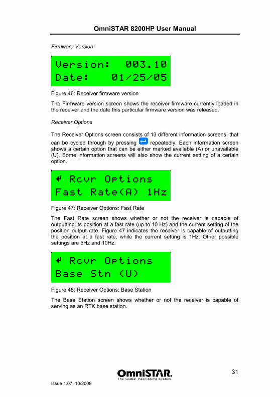
Firmware Version
Figure 46: Receiver firmware version
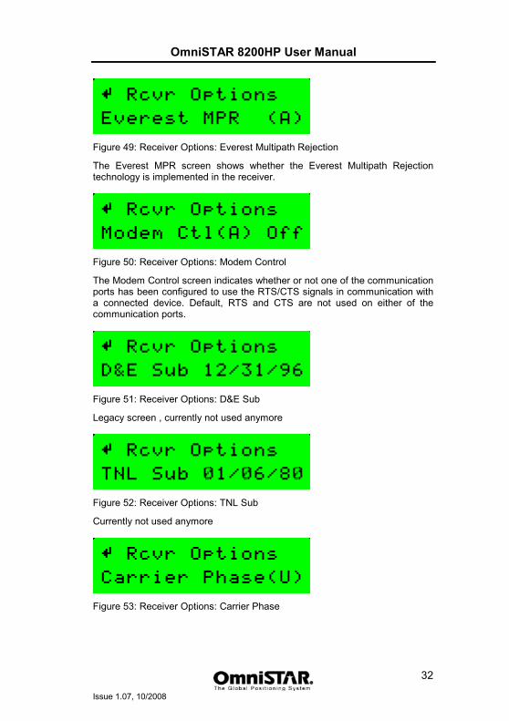
The Firmware version screen shows the receiver firmware currently loaded in the receiver and the date this particular firmware version was released. Receiver Options The Receiver Options screen consists of 13 different information screens, that can be cycled through by pressing repeatedly. Each information screen shows a certain option that can be either marked available (A) or unavailable (U). Some information screens will also show the current setting of a certain option.
Figure 47: Receiver Options: Fast Rate
The Fast Rate screen shows whether or not the receiver is capable of outputting its position at a fast rate (up to 10 Hz) and the current setting of the position output rate. Figure 47 indicates the receiver is capable of outputting the position at a fast rate, while the current setting is 1Hz. Other possible settings are 5Hz and 10Hz.
Figure 48: Receiver Options: Base Station
The Base Station screen shows whether or not the receiver is capable of serving as an RTK base station.
OmniSTAR 8200HP User Manual
Issue 1.07, 10/2008
32
Figure 49: Receiver Options: Everest Multipath Rejection
The Everest MPR screen shows whether the Everest Multipath Rejection technology is implemented in the receiver.
Figure 50: Receiver Options: Modem Control
The Modem Control screen indicates whether or not one of the communication ports has been configured to use the RTS/CTS signals in communication with a connected device. Default, RTS and CTS are not used on either of the communication ports.
Figure 51: Receiver Options: D&E Sub
Legacy screen , currently not used anymore
Figure 52: Receiver Options: TNL Sub
Currently not used anymore
Figure 53: Receiver Options: Carrier Phase
OmniSTAR 8200HP User Manual
Issue 1.07, 10/2008
33
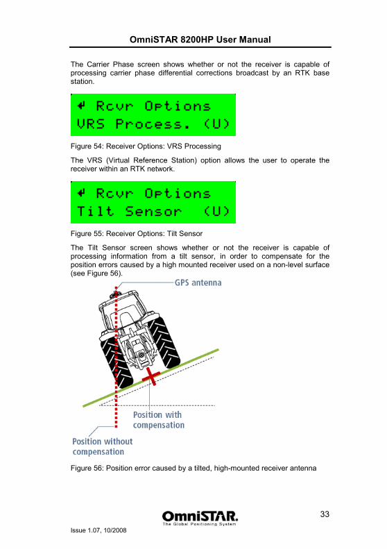
The Carrier Phase screen shows whether or not the receiver is capable of processing carrier phase differential corrections broadcast by an RTK base station.
Figure 54: Receiver Options: VRS Processing
The VRS (Virtual Reference Station) option allows the user to operate the receiver within an RTK network.
Figure 55: Receiver Options: Tilt Sensor
The Tilt Sensor screen shows whether or not the receiver is capable of processing information from a tilt sensor, in order to compensate for the position errors caused by a high mounted receiver used on a non-level surface (see Figure 56).
Figure 56: Position error caused by a tilted, high-mounted receiver antenna
OmniSTAR 8200HP User Manual
Issue 1.07, 10/2008
34
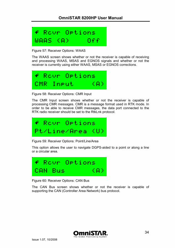
Figure 57: Receiver Options: WAAS
The WAAS screen shows whether or not the receiver is capable of receiving and processing WAAS, MSAS and EGNOS signals and whether or not the receiver is currently using either WAAS, MSAS or EGNOS corrections.
Figure 58: Receiver Options: CMR Input
The CMR Input screen shows whether or not the receiver is capable of processing CMR messages. CMR is a message format used in RTK mode. In order to be able to receive CMR messages, the data port connected to the RTK radio receiver should be set to the RtkLnk protocol.
Figure 59: Receiver Options: Point/Line/Area
This option allows the user to navigate DGPS-aided to a point or along a line or a circular area.
Figure 60: Receiver Options: CAN Bus
The CAN Bus screen shows whether or not the receiver is capable of supporting the CAN (Controller Area Network) bus protocol.
OmniSTAR 8200HP User Manual
Issue 1.07, 10/2008
35
System Voltages
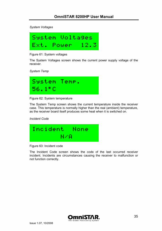
Figure 61: System voltages
The System Voltages screen shows the current power supply voltage of the receiver. System Temp
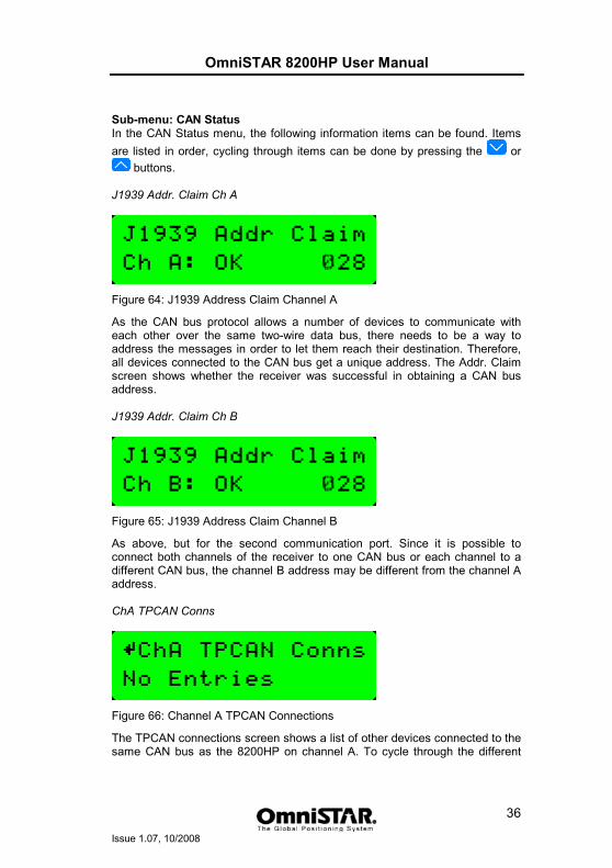
Figure 62: System temperature
The System Temp screen shows the current temperature inside the receiver case. This temperature is normally higher than the real (ambient) temperature, as the receiver board itself produces some heat when it is switched on. Incident Code
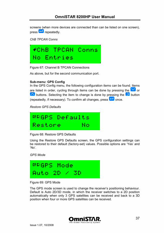
Figure 63: Incident code
The Incident Code screen shows the code of the last occurred receiver incident. Incidents are circumstances causing the receiver to malfunction or not function correctly.
OmniSTAR 8200HP User Manual
Issue 1.07, 10/2008
36
Sub-menu: CAN Status In the CAN Status menu, the following information items can be found. Items are listed in order, cycling through items can be done by pressing the or
buttons. J1939 Addr. Claim Ch A
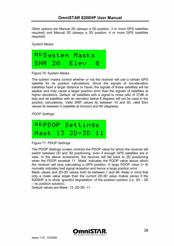
Figure 64: J1939 Address Claim Channel A
As the CAN bus protocol allows a number of devices to communicate with each other over the same two-wire data bus, there needs to be a way to address the messages in order to let them reach their destination. Therefore, all devices connected to the CAN bus get a unique address. The Addr. Claim screen shows whether the receiver was successful in obtaining a CAN bus address. J1939 Addr. Claim Ch B
Figure 65: J1939 Address Claim Channel B
As above, but for the second communication port. Since it is possible to connect both channels of the receiver to one CAN bus or each channel to a different CAN bus, the channel B address may be different from the channel A address. ChA TPCAN Conns
Figure 66: Channel A TPCAN Connections
The TPCAN connections screen shows a list of other devices connected to the same CAN bus as the 8200HP on channel A. To cycle through the different
OmniSTAR 8200HP User Manual
Issue 1.07, 10/2008
37
screens (when more devices are connected than can be listed on one screen), press repeatedly. ChB TPCAN Conns
Figure 67: Channel B TPCAN Connections
As above, but for the second communication port.
Sub-menu: GPS Config In the GPS Config menu, the following configuration items can be found. Items are listed in order, cycling through items can be done by pressing the or
buttons. Selecting the item to change is done by pressing the button (repeatedly, if necessary). To confirm all changes, press once. Restore GPS Defaults
Figure 68: Restore GPS Defaults
Using the Restore GPS Defaults screen, the GPS configuration settings can be restored to their default (factory-set) values. Possible options are ‘Yes’ and ‘No’. GPS Mode
Figure 69: GPS Mode
The GPS mode screen is used to change the receiver’s positioning behaviour. Default is Auto 2D/3D mode, in which the receiver switches to a 2D position automatically when only 3 GPS satellites can be received and back to a 3D position when four or more GPS satellites can be received.
OmniSTAR 8200HP User Manual
Issue 1.07, 10/2008
38
Other options are Manual 2D (always a 2D position, 3 or more GPS satellites required) and Manual 3D (always a 3D position, 4 or more GPS satellites required). System Masks
Figure 70: System Masks
The system masks control whether or not the receiver will use a certain GPS satellite for its position calculations. Since the signals of low-elevation satellites have a larger distance to travel, the signals of those satellites will be weaker and may cause a larger position error than the signals of satellites at higher elevations. Default, all satellites with a signal to noise ratio of 37dB or less and all satellites with an elevation below 8 degrees will not be used in the position calculations. Valid SNR values lie between 10 and 60, valid Elev values lie between 0 (satellite at horizon) and 90 (degrees). PDOP Settings
Figure 71: PDOP Settings
The PDOP Settings screen controls the PDOP value for which the receiver will switch between 2D and 3D positioning, even if enough GPS satellites are in view. In the above screenshot, the receiver will fall back to 2D positioning when the PDOP exceeds 11. ‘Mask’ indicates the PDOP value above which the receiver will stop calculating a GPS position. A large PDOP value (> 8) normally indicates bad signal reception and hence a large position error. Mask values and 2D-3D values both lie between 1 and 99. Keep in mind that only a mask value larger than the current 2D-3D value makes sense if the 8200HP is to show ‘graceful degradation’ of the position solution (i.e. 3D – 2D – no position solution). Default values are Mask: 13, 2D-3D: 11.
OmniSTAR 8200HP User Manual
Issue 1.07, 10/2008
39
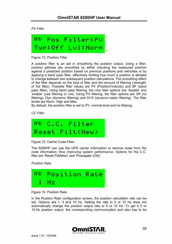
PV Filter
Figure 72: Position Filter
A position filter is an aid in smoothing the position output. Using a filter, position glitches are smoothed by either checking the measured position against a predicted position based on previous positions and velocities or by applying a band pass filter, effectively limiting how much a position is allowed to change between two subsequent position calculations. The smoothing effect of the filter depends on the kind of filter and the amount of filtering (‘strength’ of the filter). Possible filter values are PV (Position/Velocity) and BF (band pass filter). Using band pass filtering, the only filter options are ‘disable’ and ‘enable’ (use filtering or not). Using PV filtering, the filter options are Off (no filtering), Dyn (dynamic filtering) and D+S (dynamic+static filtering). The filter levels are Norm, High and Max. By default, the position filter is set to PV, normal level and no filtering. CC Filter
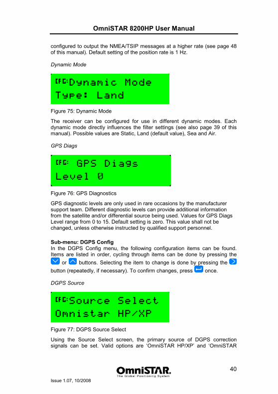
Figure 73: Carrier Code Filter
The 8200HP can use the GPS carrier information to remove noise from the code information, thus improving system performance. Options for the C.C. filter are ‘Reset Filt(New)’ and ‘Propagate (Old)’. Position Rate
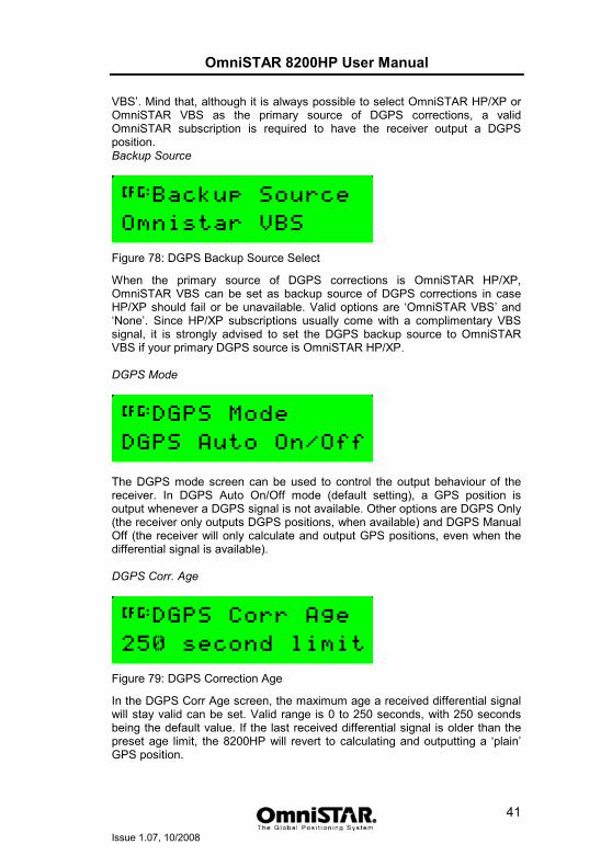
Figure 74: Position Rate
In the Position Rate configuration screen, the position calculation rate can be set. Options are 1, 5 and 10 Hz. Setting the rate to 5 or 10 Hz does not automatically change the position output rate to 5 or 10 Hz. To get a 5 or 10 Hz position output, the corresponding communication port also has to be
OmniSTAR 8200HP User Manual
Issue 1.07, 10/2008
40
configured to output the NMEA/TSIP messages at a higher rate (see page 48 of this manual). Default setting of the position rate is 1 Hz. Dynamic Mode
Figure 75: Dynamic Mode
The receiver can be configured for use in different dynamic modes. Each dynamic mode directly influences the filter settings (see also page 39 of this manual). Possible values are Static, Land (default value), Sea and Air. GPS Diags
Figure 76: GPS Diagnostics
GPS diagnostic levels are only used in rare occasions by the manufacturer support team. Different diagnostic levels can provide additional information from the satellite and/or differential source being used. Values for GPS Diags Level range from 0 to 15. Default setting is zero. This value shall not be changed, unless otherwise instructed by qualified support personnel.
Sub-menu: DGPS Config In the DGPS Config menu, the following configuration items can be found. Items are listed in order, cycling through items can be done by pressing the
or buttons. Selecting the item to change is done by pressing the button (repeatedly, if necessary). To confirm changes, press once. DGPS Source
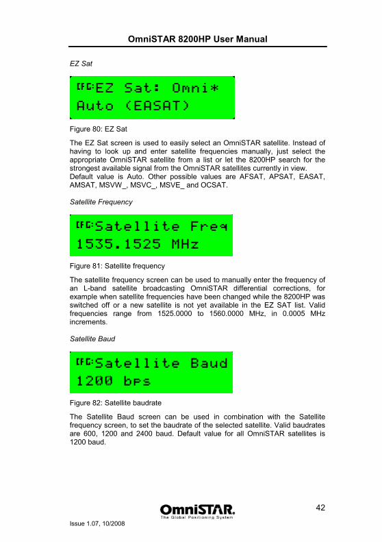
Figure 77: DGPS Source Select
Using the Source Select screen, the primary source of DGPS correction signals can be set. Valid options are ‘OmniSTAR HP/XP’ and ‘OmniSTAR
OmniSTAR 8200HP User Manual
Issue 1.07, 10/2008
41
VBS’. Mind that, although it is always possible to select OmniSTAR HP/XP or OmniSTAR VBS as the primary source of DGPS corrections, a valid OmniSTAR subscription is required to have the receiver output a DGPS position. Backup Source
Figure 78: DGPS Backup Source Select
When the primary source of DGPS corrections is OmniSTAR HP/XP, OmniSTAR VBS can be set as backup source of DGPS corrections in case HP/XP should fail or be unavailable. Valid options are ‘OmniSTAR VBS’ and ‘None’. Since HP/XP subscriptions usually come with a complimentary VBS signal, it is strongly advised to set the DGPS backup source to OmniSTAR VBS if your primary DGPS source is OmniSTAR HP/XP. DGPS Mode
The DGPS mode screen can be used to control the output behaviour of the receiver. In DGPS Auto On/Off mode (default setting), a GPS position is output whenever a DGPS signal is not available. Other options are DGPS Only (the receiver only outputs DGPS positions, when available) and DGPS Manual Off (the receiver will only calculate and output GPS positions, even when the differential signal is available). DGPS Corr. Age
Figure 79: DGPS Correction Age
In the DGPS Corr Age screen, the maximum age a received differential signal will stay valid can be set. Valid range is 0 to 250 seconds, with 250 seconds being the default value. If the last received differential signal is older than the preset age limit, the 8200HP will revert to calculating and outputting a ‘plain’ GPS position.
OmniSTAR 8200HP User Manual
Issue 1.07, 10/2008
42
EZ Sat
Figure 80: EZ Sat
The EZ Sat screen is used to easily select an OmniSTAR satellite. Instead of having to look up and enter satellite frequencies manually, just select the appropriate OmniSTAR satellite from a list or let the 8200HP search for the strongest available signal from the OmniSTAR satellites currently in view. Default value is Auto. Other possible values are AFSAT, APSAT, EASAT, AMSAT, MSVW_, MSVC_, MSVE_ and OCSAT. Satellite Frequency
Figure 81: Satellite frequency
The satellite frequency screen can be used to manually enter the frequency of an L-band satellite broadcasting OmniSTAR differential corrections, for example when satellite frequencies have been changed while the 8200HP was switched off or a new satellite is not yet available in the EZ SAT list. Valid frequencies range from 1525.0000 to 1560.0000 MHz, in 0.0005 MHz increments. Satellite Baud
Figure 82: Satellite baudrate
The Satellite Baud screen can be used in combination with the Satellite frequency screen, to set the baudrate of the selected satellite. Valid baudrates are 600, 1200 and 2400 baud. Default value for all OmniSTAR satellites is 1200 baud.
OmniSTAR 8200HP User Manual
Issue 1.07, 10/2008
43
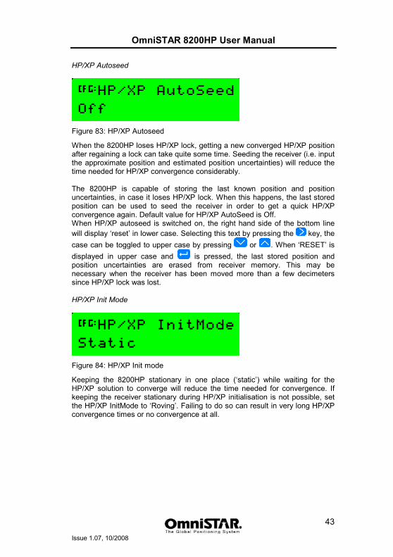
HP/XP Autoseed
Figure 83: HP/XP Autoseed
When the 8200HP loses HP/XP lock, getting a new converged HP/XP position after regaining a lock can take quite some time. Seeding the receiver (i.e. input the approximate position and estimated position uncertainties) will reduce the time needed for HP/XP convergence considerably. The 8200HP is capable of storing the last known position and position uncertainties, in case it loses HP/XP lock. When this happens, the last stored position can be used to seed the receiver in order to get a quick HP/XP convergence again. Default value for HP/XP AutoSeed is Off. When HP/XP autoseed is switched on, the right hand side of the bottom line will display ‘reset’ in lower case. Selecting this text by pressing the key, the case can be toggled to upper case by pressing or . When ‘RESET’ is displayed in upper case and is pressed, the last stored position and position uncertainties are erased from receiver memory. This may be necessary when the receiver has been moved more than a few decimeters since HP/XP lock was lost. HP/XP Init Mode
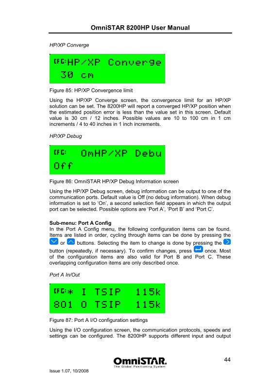
Figure 84: HP/XP Init mode
Keeping the 8200HP stationary in one place (‘static’) while waiting for the HP/XP solution to converge will reduce the time needed for convergence. If keeping the receiver stationary during HP/XP initialisation is not possible, set the HP/XP InitMode to ‘Roving’. Failing to do so can result in very long HP/XP convergence times or no convergence at all.
OmniSTAR 8200HP User Manual
Issue 1.07, 10/2008
44
HP/XP Converge
Figure 85: HP/XP Convergence limit
Using the HP/XP Converge screen, the convergence limit for an HP/XP solution can be set. The 8200HP will report a converged HP/XP position when the estimated position error is less than the value set in this screen. Default value is 30 cm / 12 inches. Possible values are 10 to 100 cm in 1 cm increments / 4 to 40 inches in 1 inch increments. HP/XP Debug
Figure 86: OmniSTAR HP/XP Debug Information screen
Using the HP/XP Debug screen, debug information can be output to one of the communication ports. Default value is Off (no debug information). When debug information is set to ‘On’, a second selection field appears in which the output port can be selected. Possible options are ‘Port A’, ‘Port B’ and ‘Port C’.
Sub-menu: Port A Config In the Port A Config menu, the following configuration items can be found. Items are listed in order, cycling through items can be done by pressing the
or buttons. Selecting the item to change is done by pressing the button (repeatedly, if necessary). To confirm changes, press once. Most of the configuration items are also valid for Port B and Port C. These overlapping configuration items are only described once. Port A In/Out
Figure 87: Port A I/O configuration settings
Using the I/O configuration screen, the communication protocols, speeds and settings can be configured. The 8200HP supports different input and output
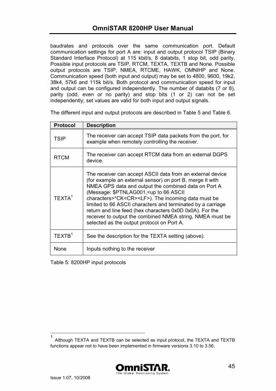
OmniSTAR 8200HP User Manual
Issue 1.07, 10/2008
45
baudrates and protocols over the same communication port. Default communication settings for port A are: input and output protocol TSIP (Binary Standard Interface Protocol) at 115 kbit/s, 8 databits, 1 stop bit, odd parity. Possible input protocols are TSIP, RTCM, TEXTA, TEXTB and None. Possible output protocols are TSIP, NMEA, RTCME, HAWK, OMNIHP and None. Communication speed (both input and output) may be set to 4800, 9600, 19k2, 38k4, 57k6 and 115k bit/s. Both protocol and communication speed for input and output can be configured independently. The number of databits (7 or 8), parity (odd, even or no parity) and stop bits (1 or 2) can not be set independently; set values are valid for both input and output signals. The different input and output protocols are described in Table 5 and Table 6.
Protocol Description
TSIP The receiver can accept TSIP data packets from the port, for example when remotely controlling the receiver.
RTCM The receiver can accept RTCM data from an external DGPS device.
TEXTA1
The receiver can accept ASCII data from an external device (for example an external sensor) on port B, merge it with NMEA GPS data and output the combined data on Port A (Message: $PTNLAG001,<up to 66 ASCII characters>*CK<CR><LF>). The incoming data must be limited to 66 ASCII characters and terminated by a carriage return and line feed (hex characters 0x0D 0x0A). For the receiver to output the combined NMEA string, NMEA must be selected as the output protocol on Port A.
TEXTB1 See the description for the TEXTA setting (above).
None Inputs nothing to the receiver
Table 5: 8200HP input protocols
1
Although TEXTA and TEXTB can be selected as input protocol, the TEXTA and TEXTB functions appear not to have been implemented in firmware versions 3.10 to 3.56.
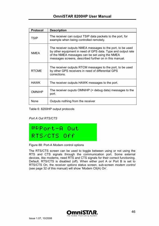
OmniSTAR 8200HP User Manual
Issue 1.07, 10/2008
46
Protocol Description
TSIP The receiver can output TSIP data packets to the port, for example when being controlled remotely.
NMEA
The receiver outputs NMEA messages to the port, to be used by other equipment in need of GPS data. Type and output rate of the NMEA messages can be set using the NMEA messages screens, described further on in this manual.
RTCME The receiver outputs RTCM messages to the port, to be used by other GPS receivers in need of differential GPS corrections.
HAWK The receiver outputs HAWK messages to the port.
OMNIHP The receiver ouputs OMNIHP (= debug data) messages to the port.
None Outputs nothing from the receiver
Table 6: 8200HP output protocols
Port A Out RTS/CTS
Figure 88: Port-A Modem control options
The RTS/CTS screen can be used to toggle between using or not using the RTS and CTS signals through the communication port. Some external devices, like modems, need RTS and CTS signals for their correct functioning. Default, RTS/CTS is disabled (off). When either port A or Port B is set to RTS/CTS On, the receiver options status screen, sub-screen modem control (see page 32 of this manual) will show ‘Modem Ctl(A) On’.
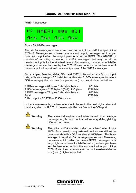
OmniSTAR 8200HP User Manual
Issue 1.07, 10/2008
47
NMEA1 Messages
Figure 89: NMEA messages 1
The NMEA messages screens are used to control the NMEA output of the 8200HP. Messages set in lower case are not output, messages set in upper case are output when the output protocol is set to NMEA. The 8200HP is capable of outputting a number of NMEA messages, that may not all be needed as inputs for the attached device. Furthermore, the number of NMEA messages that can be sent by the 8200HP also depends on the baudrate of the communication port and the set output rate of the NMEA messages. For example: Selecting GGA, GSV and RMC to be output at a 5 Hz. output rate, with an average of 8 satellites in view (so 2 GSV messages for every GGA message), the baudrate (bits per second) can be calculated as follows: 1 GGA-message = 89 bytes * (8+1) bits/byte = 801 bits 2 GSV messages = 2*72 bytes * (8+1) bits/byte = 1296 bits 1 RMC message = 77 bytes * (8+1) bits/byte = 693 bits Total 2790 bits 5 Hz. output = 5 * 2790 = 13950 bits/sec. In the above example, the baudrate should be set to the next higher standard baudrate, which is 19,200, to prevent a buffer overflow of the COM-port.
Warning: The above calculation is indicative, based on an average message length count. Actual values may differ, yielding different outcomes.
Warning: The initial NMEA standard called for a baud rate of only 4800. As a result, many external devices are still set to communicate with a GPS receiver at 4800 baud. This is an average of only 6 NMEA messages per second. Therefore, be aware not to select too many NMEA messages or a very high output rate for NMEA output, unless you have set the baudrate on both the communication port of the 8200HP and the communication port of the external device to a (much) higher value first.
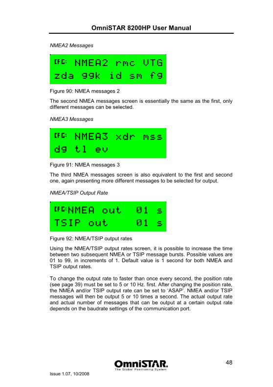
OmniSTAR 8200HP User Manual
Issue 1.07, 10/2008
48
NMEA2 Messages
Figure 90: NMEA messages 2
The second NMEA messages screen is essentially the same as the first, only different messages can be selected. NMEA3 Messages
Figure 91: NMEA messages 3
The third NMEA messages screen is also equivalent to the first and second one, again presenting more different messages to be selected for output. NMEA/TSIP Output Rate
Figure 92: NMEA/TSIP output rates
Using the NMEA/TSIP output rates screen, it is possible to increase the time between two subsequent NMEA or TSIP message bursts. Possible values are 01 to 99, in increments of 1. Default value is 1 second for both NMEA and TSIP output rates. To change the output rate to faster than once every second, the position rate (see page 39) must be set to 5 or 10 Hz. first. After changing the position rate, the NMEA and/or TSIP output rate can be set to ‘ASAP’. NMEA and/or TSIP messages will then be output 5 or 10 times a second. The actual output rate and actual number of messages that can be output at a certain output rate depends on the baudrate settings of the communication port.
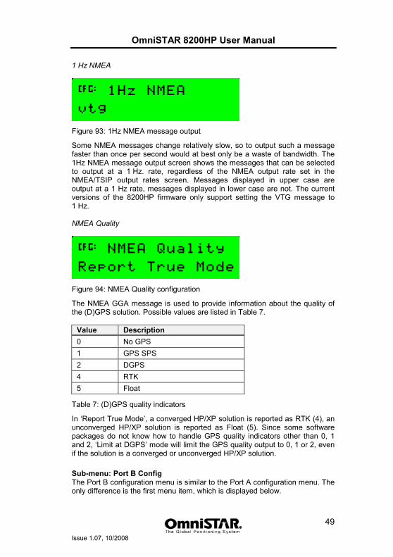
OmniSTAR 8200HP User Manual
Issue 1.07, 10/2008
49
1 Hz NMEA
Figure 93: 1Hz NMEA message output
Some NMEA messages change relatively slow, so to output such a message faster than once per second would at best only be a waste of bandwidth. The 1Hz NMEA message output screen shows the messages that can be selected to output at a 1 Hz. rate, regardless of the NMEA output rate set in the NMEA/TSIP output rates screen. Messages displayed in upper case are output at a 1 Hz rate, messages displayed in lower case are not. The current versions of the 8200HP firmware only support setting the VTG message to 1 Hz. NMEA Quality
Figure 94: NMEA Quality configuration
The NMEA GGA message is used to provide information about the quality of the (D)GPS solution. Possible values are listed in Table 7.
Value Description 0 No GPS 1 GPS SPS 2 DGPS 4 RTK 5 Float
Table 7: (D)GPS quality indicators
In ‘Report True Mode’, a converged HP/XP solution is reported as RTK (4), an unconverged HP/XP solution is reported as Float (5). Since some software packages do not know how to handle GPS quality indicators other than 0, 1 and 2, ‘Limit at DGPS’ mode will limit the GPS quality output to 0, 1 or 2, even if the solution is a converged or unconverged HP/XP solution.
Sub-menu: Port B Config The Port B configuration menu is similar to the Port A configuration menu. The only difference is the first menu item, which is displayed below.
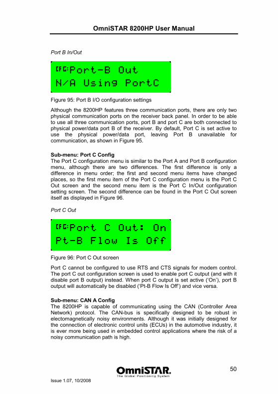
OmniSTAR 8200HP User Manual
Issue 1.07, 10/2008
50
Port B In/Out
Figure 95: Port B I/O configuration settings
Although the 8200HP features three communication ports, there are only two physical communication ports on the receiver back panel. In order to be able to use all three communication ports, port B and port C are both connected to physical power/data port B of the receiver. By default, Port C is set active to use the physical power/data port, leaving Port B unavailable for communication, as shown in Figure 95.
Sub-menu: Port C Config The Port C configuration menu is similar to the Port A and Port B configuration menu, although there are two differences. The first difference is only a difference in menu order; the first and second menu items have changed places, so the first menu item of the Port C configuration menu is the Port C Out screen and the second menu item is the Port C In/Out configuration setting screen. The second difference can be found in the Port C Out screen itself as displayed in Figure 96. Port C Out
Figure 96: Port C Out screen
Port C cannot be configured to use RTS and CTS signals for modem control. The port C out configuration screen is used to enable port C output (and with it disable port B output) instead. When port C output is set active (‘On’), port B output will automatically be disabled (‘Pt-B Flow Is Off’) and vice versa.
Sub-menu: CAN A Config The 8200HP is capable of communicating using the CAN (Controller Area Network) protocol. The CAN-bus is specifically designed to be robust in electomagnetically noisy environments. Although it was initially designed for the connection of electronic control units (ECUs) in the automotive industry, it is ever more being used in embedded control applications where the risk of a noisy communication path is high.
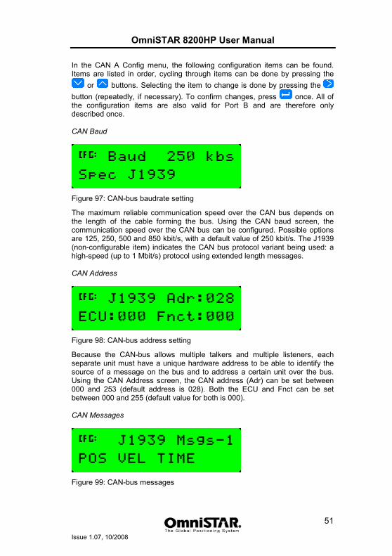
OmniSTAR 8200HP User Manual
Issue 1.07, 10/2008
51
In the CAN A Config menu, the following configuration items can be found. Items are listed in order, cycling through items can be done by pressing the
or buttons. Selecting the item to change is done by pressing the button (repeatedly, if necessary). To confirm changes, press once. All of the configuration items are also valid for Port B and are therefore only described once. CAN Baud
Figure 97: CAN-bus baudrate setting
The maximum reliable communication speed over the CAN bus depends on the length of the cable forming the bus. Using the CAN baud screen, the communication speed over the CAN bus can be configured. Possible options are 125, 250, 500 and 850 kbit/s, with a default value of 250 kbit/s. The J1939 (non-configurable item) indicates the CAN bus protocol variant being used: a high-speed (up to 1 Mbit/s) protocol using extended length messages. CAN Address
Figure 98: CAN-bus address setting
Because the CAN-bus allows multiple talkers and multiple listeners, each separate unit must have a unique hardware address to be able to identify the source of a message on the bus and to address a certain unit over the bus. Using the CAN Address screen, the CAN address (Adr) can be set between 000 and 253 (default address is 028). Both the ECU and Fnct can be set between 000 and 255 (default value for both is 000). CAN Messages
Figure 99: CAN-bus messages
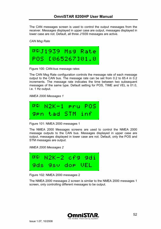
OmniSTAR 8200HP User Manual
Issue 1.07, 10/2008
52
The CAN messages screen is used to control the output messages from the receiver. Messages displayed in upper case are output, messages displayed in lower case are not. Default, all three J1939 messages are active. CAN Msg Rate
Figure 100: CAN-bus message rates
The CAN Msg Rate configuration controls the message rate of each message output to the CAN bus. The message rate can be set from 0.2 to 65.4 in 0.2 increments. The message rate indicates the time between two subsequent messages of the same type. Default setting for POS, TIME and VEL is 01.0, i.e. 1 Hz output. NMEA 2000 Messages 1
Figure 101: NMEA 2000 messages 1
The NMEA 2000 Messages screens are used to control the NMEA 2000 message outputs to the CAN bus. Messages displayed in upper case are output, messages displayed in lower case are not. Default, only the POS and STM messages are output. NMEA 2000 Messages 2
Figure 102: NMEA 2000 messages 2
The NMEA 2000 messages 2 screen is similar to the NMEA 2000 messages 1 screen, only controlling different messages to be output.
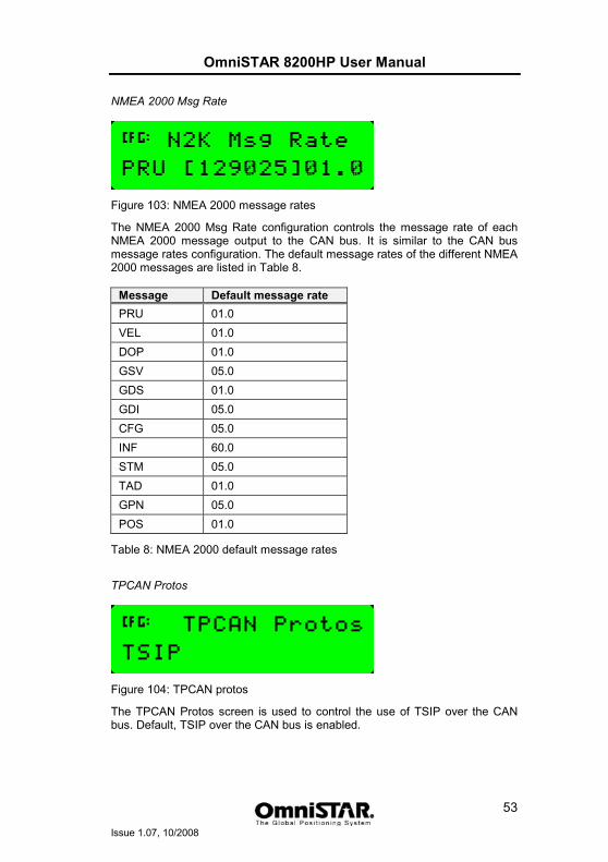
OmniSTAR 8200HP User Manual
Issue 1.07, 10/2008
53
NMEA 2000 Msg Rate
Figure 103: NMEA 2000 message rates
The NMEA 2000 Msg Rate configuration controls the message rate of each NMEA 2000 message output to the CAN bus. It is similar to the CAN bus message rates configuration. The default message rates of the different NMEA 2000 messages are listed in Table 8.
Message Default message rate PRU 01.0 VEL 01.0 DOP 01.0 GSV 05.0 GDS 01.0 GDI 05.0 CFG 05.0 INF 60.0 STM 05.0 TAD 01.0 GPN 05.0 POS 01.0
Table 8: NMEA 2000 default message rates
TPCAN Protos
Figure 104: TPCAN protos
The TPCAN Protos screen is used to control the use of TSIP over the CAN bus. Default, TSIP over the CAN bus is enabled.
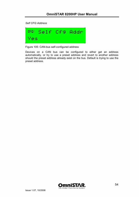
OmniSTAR 8200HP User Manual
Issue 1.07, 10/2008
54
Self CFG Address
Figure 105: CAN-bus self-configured address
Devices on a CAN bus can be configured to either get an address automatically, or try to use a preset address and revert to another address should the preset address already exist on the bus. Default is trying to use the preset address.
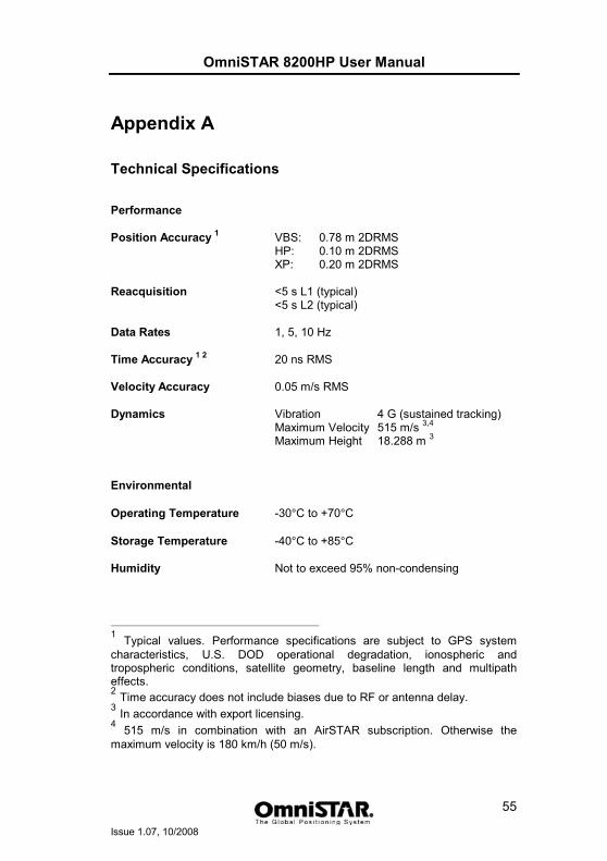
OmniSTAR 8200HP User Manual
Issue 1.07, 10/2008
55
Appendix A
Technical Specifications
Performance Position Accuracy 1 VBS: 0.78 m 2DRMS HP: 0.10 m 2DRMS XP: 0.20 m 2DRMS Reacquisition <5 s L1 (typical) <5 s L2 (typical) Data Rates 1, 5, 10 Hz Time Accuracy 1 2 20 ns RMS Velocity Accuracy 0.05 m/s RMS Dynamics Vibration 4 G (sustained tracking) Maximum Velocity 515 m/s 3,4
Maximum Height 18.288 m 3
Environmental Operating Temperature -30°C to +70°C
Storage Temperature -40°C to +85°C
Humidity Not to exceed 95% non-condensing
1 Typical values. Performance specifications are subject to GPS system characteristics, U.S. DOD operational degradation, ionospheric and tropospheric conditions, satellite geometry, baseline length and multipath effects. 2 Time accuracy does not include biases due to RF or antenna delay. 3 In accordance with export licensing. 4 515 m/s in combination with an AirSTAR subscription. Otherwise the maximum velocity is 180 km/h (50 m/s).
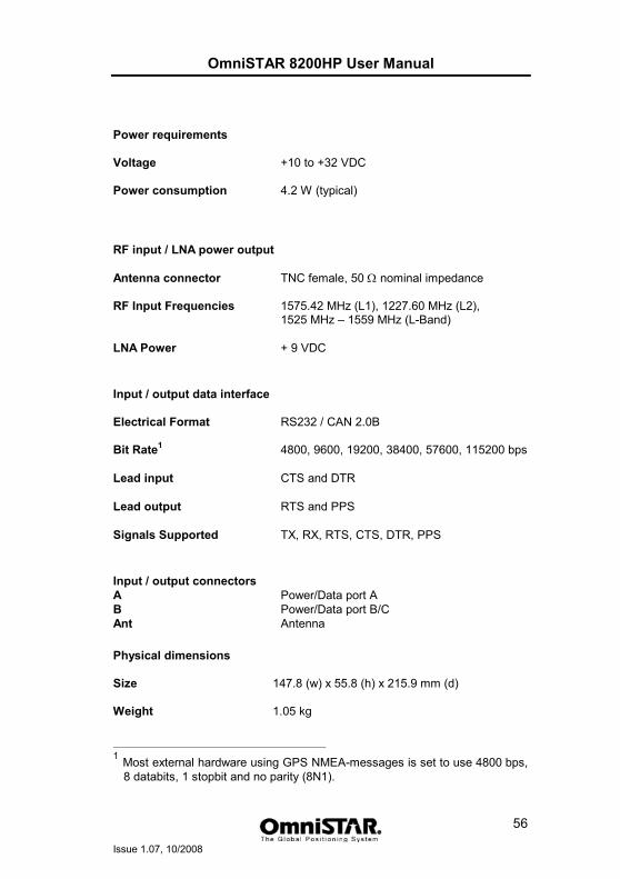
OmniSTAR 8200HP User Manual
Issue 1.07, 10/2008
56
Power requirements Voltage +10 to +32 VDC Power consumption 4.2 W (typical)
RF input / LNA power output Antenna connector TNC female, 50 Ω nominal impedance RF Input Frequencies 1575.42 MHz (L1), 1227.60 MHz (L2), 1525 MHz – 1559 MHz (L-Band) LNA Power + 9 VDC
Input / output data interface Electrical Format RS232 / CAN 2.0B Bit Rate1 4800, 9600, 19200, 38400, 57600, 115200 bps Lead input CTS and DTR Lead output RTS and PPS Signals Supported TX, RX, RTS, CTS, DTR, PPS
Input / output connectors A Power/Data port A B Power/Data port B/C Ant Antenna
Physical dimensions Size 147.8 (w) x 55.8 (h) x 215.9 mm (d) Weight 1.05 kg
1 Most external hardware using GPS NMEA-messages is set to use 4800 bps,
8 databits, 1 stopbit and no parity (8N1).
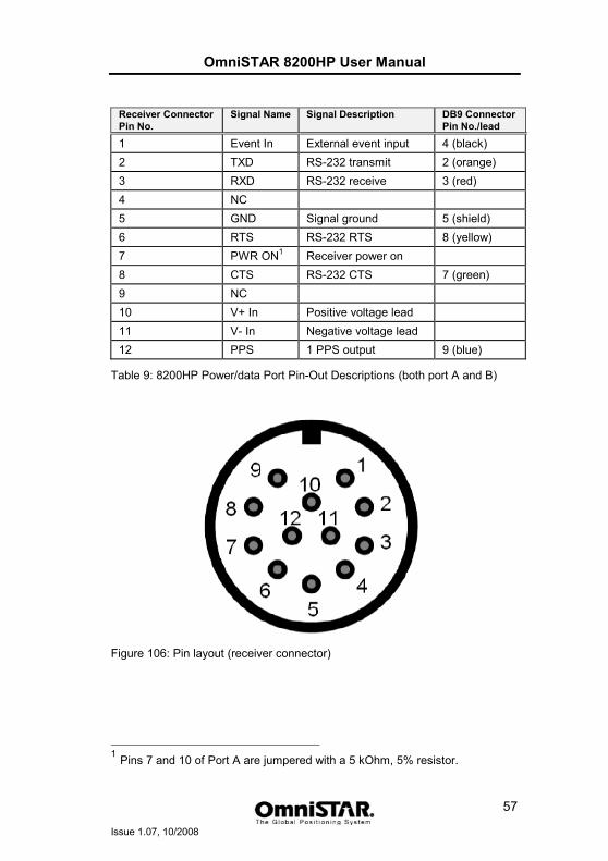
OmniSTAR 8200HP User Manual
Issue 1.07, 10/2008
57
Receiver Connector Pin No.
Signal Name Signal Description DB9 Connector Pin No./lead
1 Event In External event input 4 (black) 2 TXD RS-232 transmit 2 (orange) 3 RXD RS-232 receive 3 (red) 4 NC 5 GND Signal ground 5 (shield) 6 RTS RS-232 RTS 8 (yellow) 7 PWR ON1 Receiver power on 8 CTS RS-232 CTS 7 (green) 9 NC 10 V+ In Positive voltage lead 11 V- In Negative voltage lead 12 PPS 1 PPS output 9 (blue)
Table 9: 8200HP Power/data Port Pin-Out Descriptions (both port A and B)
Figure 106: Pin layout (receiver connector)
1 Pins 7 and 10 of Port A are jumpered with a 5 kOhm, 5% resistor.
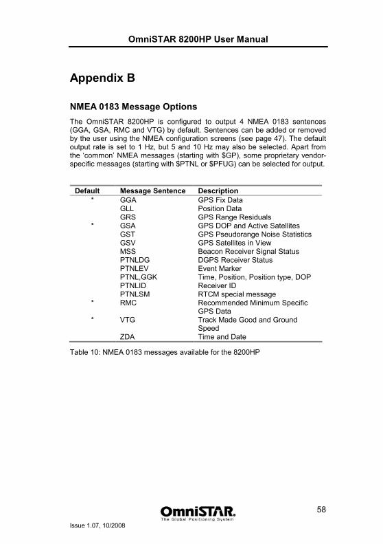
OmniSTAR 8200HP User Manual
Issue 1.07, 10/2008
58
Appendix B
NMEA 0183 Message Options The OmniSTAR 8200HP is configured to output 4 NMEA 0183 sentences (GGA, GSA, RMC and VTG) by default. Sentences can be added or removed by the user using the NMEA configuration screens (see page 47). The default output rate is set to 1 Hz, but 5 and 10 Hz may also be selected. Apart from the ‘common’ NMEA messages (starting with $GP), some proprietary vendor-specific messages (starting with $PTNL or $PFUG) can be selected for output.
Default Message Sentence Description * GGA GPS Fix Data
GLL Position Data GRS GPS Range Residuals * GSA GPS DOP and Active Satellites GST GPS Pseudorange Noise Statistics GSV GPS Satellites in View MSS Beacon Receiver Signal Status PTNLDG DGPS Receiver Status PTNLEV Event Marker PTNL,GGK Time, Position, Position type, DOP PTNLID Receiver ID PTNLSM RTCM special message * RMC Recommended Minimum Specific
GPS Data * VTG Track Made Good and Ground
Speed ZDA Time and Date
Table 10: NMEA 0183 messages available for the 8200HP
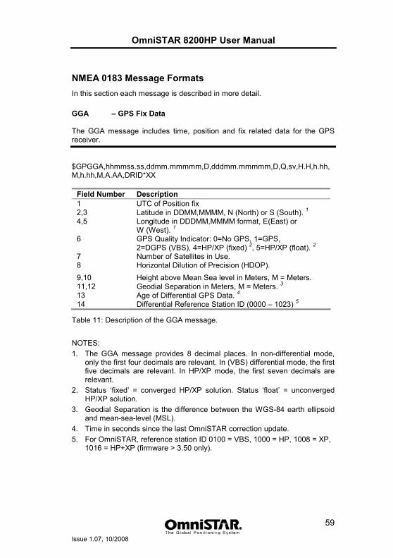
OmniSTAR 8200HP User Manual
Issue 1.07, 10/2008
59
NMEA 0183 Message Formats In this section each message is described in more detail.
GGA – GPS Fix Data The GGA message includes time, position and fix related data for the GPS receiver.
$GPGGA,hhmmss.ss,ddmm.mmmmm,D,dddmm.mmmmm,D,Q,sv,H.H,h.hh,M,h.hh,M,A.AA,DRID*XX
Field Number Description 1 UTC of Position fix 2,3 Latitude in DDMM,MMMM, N (North) or S (South). 14,5 Longitude in DDDMM,MMMM format, E(East) or
W (West). 16 GPS Quality Indicator: 0=No GPS, 1=GPS,
2=DGPS (VBS), 4=HP/XP (fixed) 2, 5=HP/XP (float). 27 Number of Satellites in Use. 8 Horizontal Dilution of Precision (HDOP). 9,10 Height above Mean Sea level in Meters, M = Meters. 11,12 Geodial Separation in Meters, M = Meters. 313 Age of Differential GPS Data. 414 Differential Reference Station ID (0000 – 1023) 5
Table 11: Description of the GGA message.
NOTES: 1. The GGA message provides 8 decimal places. In non-differential mode,
only the first four decimals are relevant. In (VBS) differential mode, the first five decimals are relevant. In HP/XP mode, the first seven decimals are relevant.
2. Status ‘fixed’ = converged HP/XP solution. Status ‘float’ = unconverged HP/XP solution.
3. Geodial Separation is the difference between the WGS-84 earth ellipsoid and mean-sea-level (MSL).
4. Time in seconds since the last OmniSTAR correction update. 5. For OmniSTAR, reference station ID 0100 = VBS, 1000 = HP, 1008 = XP,
1016 = HP+XP (firmware > 3.50 only).
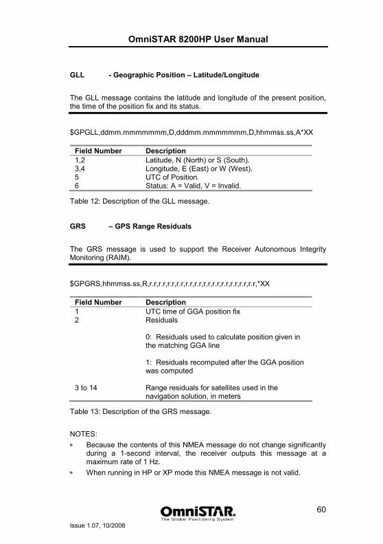
OmniSTAR 8200HP User Manual
Issue 1.07, 10/2008
60
GLL - Geographic Position – Latitude/Longitude
The GLL message contains the latitude and longitude of the present position, the time of the position fix and its status.
$GPGLL,ddmm.mmmmmmm,D,dddmm.mmmmmmm,D,hhmmss.ss,A*XX
Field Number Description 1,2 Latitude, N (North) or S (South). 3,4 Longitude, E (East) or W (West). 5 UTC of Position. 6 Status: A = Valid, V = Invalid.
Table 12: Description of the GLL message.
GRS – GPS Range Residuals
The GRS message is used to support the Receiver Autonomous Integrity Monitoring (RAIM).
$GPGRS,hhmmss.ss,R,r.r,r.r,r.r,r.r,r.r,r.r,r.r,r.r,r.r,r.r,r.r,r.r,*XX
Field Number Description 1 UTC time of GGA position fix 2 Residuals
0: Residuals used to calculate position given in the matching GGA line 1: Residuals recomputed after the GGA position was computed
3 to 14 Range residuals for satellites used in the navigation solution, in meters
Table 13: Description of the GRS message.
NOTES: ∗ Because the contents of this NMEA message do not change significantly
during a 1-second interval, the receiver outputs this message at a maximum rate of 1 Hz.
∗ When running in HP or XP mode this NMEA message is not valid.
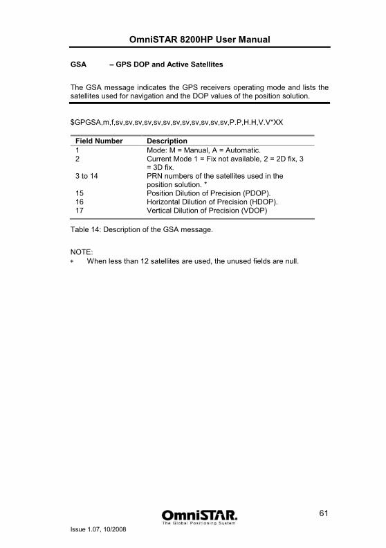
OmniSTAR 8200HP User Manual
Issue 1.07, 10/2008
61
GSA – GPS DOP and Active Satellites
The GSA message indicates the GPS receivers operating mode and lists the satellites used for navigation and the DOP values of the position solution.
$GPGSA,m,f,sv,sv,sv,sv,sv,sv,sv,sv,sv,sv,sv,sv,P.P,H.H,V.V*XX
Field Number Description 1 Mode: M = Manual, A = Automatic. 2 Current Mode 1 = Fix not available, 2 = 2D fix, 3
= 3D fix. 3 to 14 PRN numbers of the satellites used in the
position solution. *15 Position Dilution of Precision (PDOP). 16 Horizontal Dilution of Precision (HDOP). 17 Vertical Dilution of Precision (VDOP)
Table 14: Description of the GSA message.
NOTE: ∗ When less than 12 satellites are used, the unused fields are null.
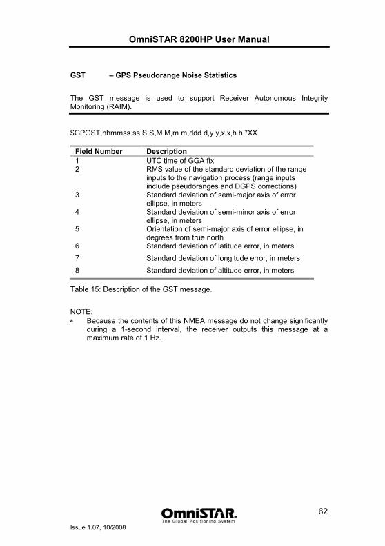
OmniSTAR 8200HP User Manual
Issue 1.07, 10/2008
62
GST – GPS Pseudorange Noise Statistics
The GST message is used to support Receiver Autonomous Integrity Monitoring (RAIM).
$GPGST,hhmmss.ss,S.S,M.M,m.m,ddd.d,y.y,x.x,h.h,*XX
Field Number Description 1 UTC time of GGA fix 2 RMS value of the standard deviation of the range
inputs to the navigation process (range inputs include pseudoranges and DGPS corrections)
3 Standard deviation of semi-major axis of error ellipse, in meters
4 Standard deviation of semi-minor axis of error ellipse, in meters
5 Orientation of semi-major axis of error ellipse, in degrees from true north
6 Standard deviation of latitude error, in meters 7 Standard deviation of longitude error, in meters 8 Standard deviation of altitude error, in meters
Table 15: Description of the GST message.
NOTE: ∗ Because the contents of this NMEA message do not change significantly
during a 1-second interval, the receiver outputs this message at a maximum rate of 1 Hz.
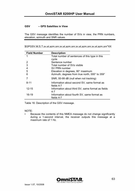
OmniSTAR 8200HP User Manual
Issue 1.07, 10/2008
63
GSV – GPS Satellites in View
The GSV message identifies the number of SVs in view, the PRN numbers, elevation, azimuth and SNR values.
$GPGSV,M,S,T,sv,el,azm,snr,sv,el,azm,snr,sv,el,azm,snr,sv,el,azm,snr*XX
Field Number Description 1 Total number of sentences of this type in this
cycle 2 Sentence number 3 Total number of SVs visible 4 SV PRN number 5 Elevation in degrees, 90° maximum 6 Azimuth, degrees from true north, 000° to 359° 7 SNR, 00-99 dB (null when not tracking) 8-11 Information about second SV, same format as
fields 4-7 12-15 Information about third SV, same format as fields
4-7 16-19 Information about fourth SV, same format as
fields 4-7
Table 16: Description of the GSV message.
NOTE: ∗ Because the contents of this NMEA message do not change significantly
during a 1-second interval, the receiver outputs this message at a maximum rate of 1 Hz.
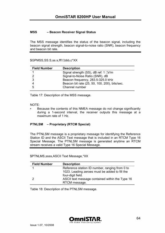
OmniSTAR 8200HP User Manual
Issue 1.07, 10/2008
64
MSS – Beacon Receiver Signal Status
The MSS message identifies the status of the beacon signal, including the beacon signal strength, beacon signal-to-noise ratio (SNR), beacon frequency and beacon bit rate.
$GPMSS,SS.S,ss.s,fff.f,bbb,c*XX
Field Number Description 1 Signal strength (SS), dB ref: 1 µV/m 2 Signal-to-Noise Ratio (SNR), dB 3 Beacon frequency, 283.5-325.0 kHz 4 Beacon bit rate (25, 50, 100, 200), bits/sec. 5 Channel number
Table 17: Description of the MSS message.
NOTE: ∗ Because the contents of this NMEA message do not change significantly
during a 1-second interval, the receiver outputs this message at a maximum rate of 1 Hz.
PTNLSM – Proprietary (RTCM Special)
The PTNLSM message is a proprietary message for identifying the Reference Station ID and the ASCII Text message that is included in an RTCM Type 16 Special Message. The PTNLSM message is generated anytime an RTCM stream receives a valid Type 16 Special Message.
$PTNLMS,ssss,ASCII Text Message,*XX
Field Number Description 1 Reference station ID number, ranging from 0 to
1023. Leading zeroes must be added to fill the four-digit field.
2 ASCII text message contained within the Type 16 RTCM message.
Table 18: Description of the PTNLSM message.
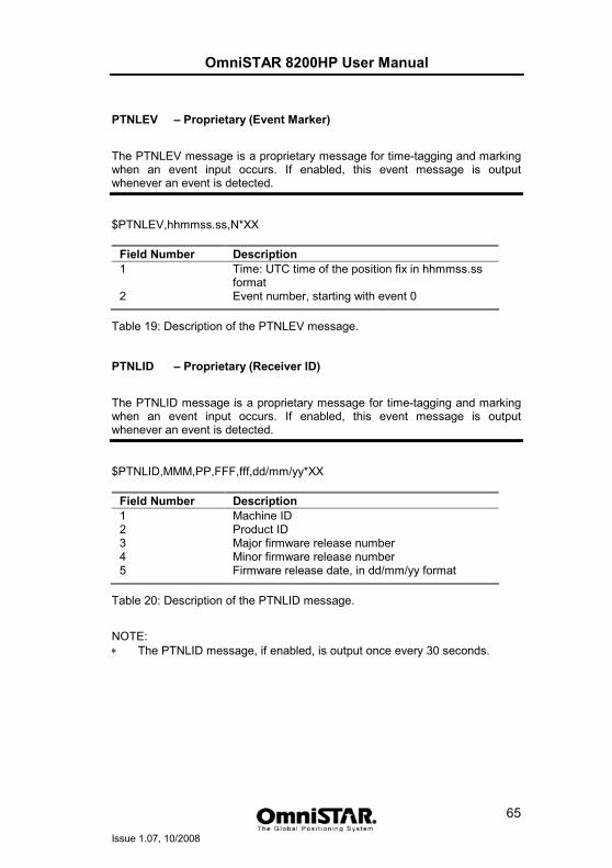
OmniSTAR 8200HP User Manual
Issue 1.07, 10/2008
65
PTNLEV – Proprietary (Event Marker)
The PTNLEV message is a proprietary message for time-tagging and marking when an event input occurs. If enabled, this event message is output whenever an event is detected.
$PTNLEV,hhmmss.ss,N*XX
Field Number Description 1 Time: UTC time of the position fix in hhmmss.ss
format 2 Event number, starting with event 0
Table 19: Description of the PTNLEV message.
PTNLID – Proprietary (Receiver ID)
The PTNLID message is a proprietary message for time-tagging and marking when an event input occurs. If enabled, this event message is output whenever an event is detected.
$PTNLID,MMM,PP,FFF,fff,dd/mm/yy*XX
Field Number Description 1 Machine ID 2 Product ID 3 Major firmware release number 4 Minor firmware release number 5 Firmware release date, in dd/mm/yy format
Table 20: Description of the PTNLID message.
NOTE: ∗ The PTNLID message, if enabled, is output once every 30 seconds.
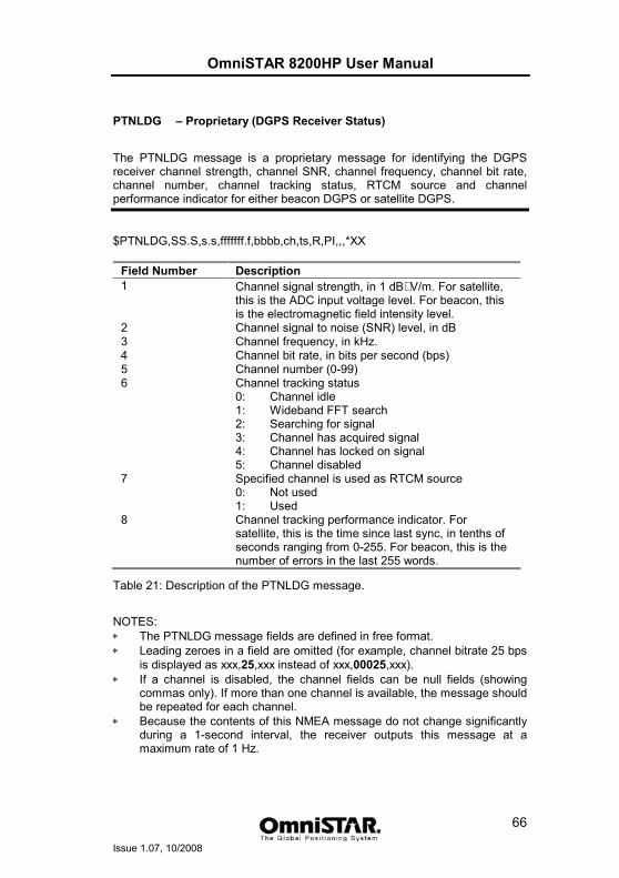
OmniSTAR 8200HP User Manual
Issue 1.07, 10/2008
66
PTNLDG – Proprietary (DGPS Receiver Status)
The PTNLDG message is a proprietary message for identifying the DGPS receiver channel strength, channel SNR, channel frequency, channel bit rate, channel number, channel tracking status, RTCM source and channel performance indicator for either beacon DGPS or satellite DGPS.
$PTNLDG,SS.S,s.s,fffffff.f,bbbb,ch,ts,R,PI,,,*XX
Field Number Description 1 Channel signal strength, in 1 dBµV/m. For satellite,
this is the ADC input voltage level. For beacon, this is the electromagnetic field intensity level.
2 Channel signal to noise (SNR) level, in dB 3 Channel frequency, in kHz. 4 Channel bit rate, in bits per second (bps) 5 Channel number (0-99) 6 Channel tracking status
0: Channel idle 1: Wideband FFT search 2: Searching for signal 3: Channel has acquired signal 4: Channel has locked on signal 5: Channel disabled
7 Specified channel is used as RTCM source 0: Not used 1: Used
8 Channel tracking performance indicator. For satellite, this is the time since last sync, in tenths of seconds ranging from 0-255. For beacon, this is the number of errors in the last 255 words.
Table 21: Description of the PTNLDG message.
NOTES: ∗ The PTNLDG message fields are defined in free format. ∗ Leading zeroes in a field are omitted (for example, channel bitrate 25 bps
is displayed as xxx,25,xxx instead of xxx,00025,xxx). ∗ If a channel is disabled, the channel fields can be null fields (showing
commas only). If more than one channel is available, the message should be repeated for each channel.
∗ Because the contents of this NMEA message do not change significantly during a 1-second interval, the receiver outputs this message at a maximum rate of 1 Hz.
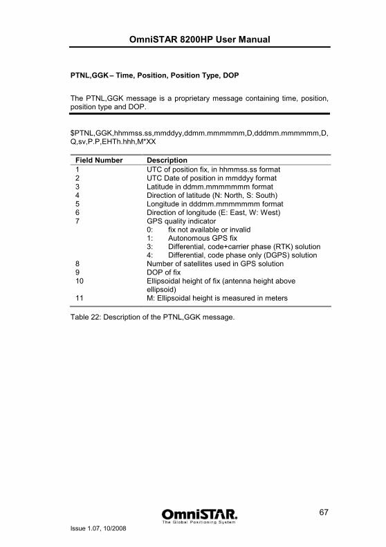
OmniSTAR 8200HP User Manual
Issue 1.07, 10/2008
67
PTNL,GGK – Time, Position, Position Type, DOP
The PTNL,GGK message is a proprietary message containing time, position, position type and DOP.
$PTNL,GGK,hhmmss.ss,mmddyy,ddmm.mmmmmm,D,dddmm.mmmmmm,D, Q,sv,P.P,EHTh.hhh,M*XX
Field Number Description 1 UTC of position fix, in hhmmss.ss format 2 UTC Date of position in mmddyy format 3 Latitude in ddmm.mmmmmmm format 4 Direction of latitude (N: North, S: South) 5 Longitude in dddmm.mmmmmmm format 6 Direction of longitude (E: East, W: West) 7 GPS quality indicator
0: fix not available or invalid 1: Autonomous GPS fix 3: Differential, code+carrier phase (RTK) solution 4: Differential, code phase only (DGPS) solution
8 Number of satellites used in GPS solution 9 DOP of fix 10 Ellipsoidal height of fix (antenna height above
ellipsoid) 11 M: Ellipsoidal height is measured in meters
Table 22: Description of the PTNL,GGK message.
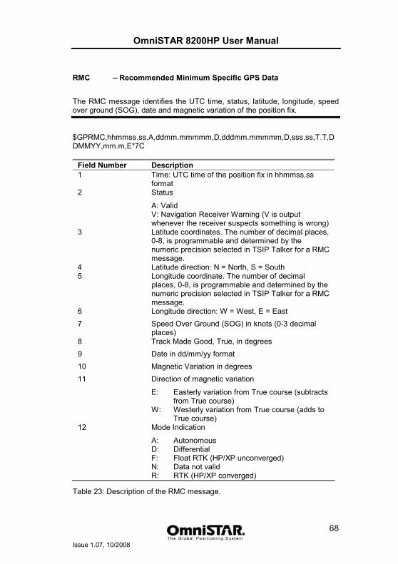
OmniSTAR 8200HP User Manual
Issue 1.07, 10/2008
68
RMC – Recommended Minimum Specific GPS Data
The RMC message identifies the UTC time, status, latitude, longitude, speed over ground (SOG), date and magnetic variation of the position fix.
$GPRMC,hhmmss.ss,A,ddmm.mmmmm,D,dddmm.mmmmm,D,sss.ss,T.T,DDMMYY,mm.m,E*7C
Field Number Description 1 Time: UTC time of the position fix in hhmmss.ss
format 2 Status
A: Valid V: Navigation Receiver Warning (V is output whenever the receiver suspects something is wrong)
3 Latitude coordinates. The number of decimal places, 0-8, is programmable and determined by the numeric precision selected in TSIP Talker for a RMC message.
4 Latitude direction: N = North, S = South 5 Longitude coordinate. The number of decimal
places, 0-8, is programmable and determined by the numeric precision selected in TSIP Talker for a RMC message.
6 Longitude direction: W = West, E = East 7 Speed Over Ground (SOG) in knots (0-3 decimal
places) 8 Track Made Good, True, in degrees 9 Date in dd/mm/yy format 10 Magnetic Variation in degrees 11 Direction of magnetic variation
E: Easterly variation from True course (subtracts from True course)
W: Westerly variation from True course (adds to True course)
12 Mode Indication
A: Autonomous D: Differential F: Float RTK (HP/XP unconverged) N: Data not valid R: RTK (HP/XP converged)
Table 23: Description of the RMC message.
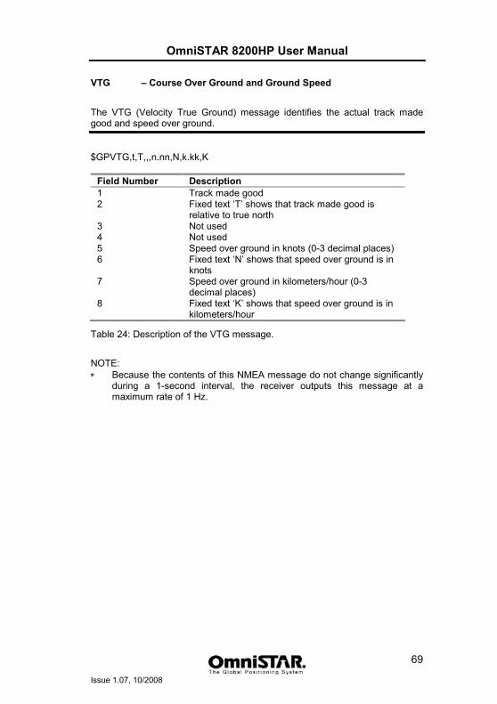
OmniSTAR 8200HP User Manual
Issue 1.07, 10/2008
69
VTG – Course Over Ground and Ground Speed
The VTG (Velocity True Ground) message identifies the actual track made good and speed over ground.
$GPVTG,t,T,,,n.nn,N,k.kk,K
Field Number Description 1 Track made good 2 Fixed text ‘T’ shows that track made good is
relative to true north 3 Not used 4 Not used 5 Speed over ground in knots (0-3 decimal places) 6 Fixed text ‘N’ shows that speed over ground is in
knots 7 Speed over ground in kilometers/hour (0-3
decimal places) 8 Fixed text ‘K’ shows that speed over ground is in
kilometers/hour
Table 24: Description of the VTG message.
NOTE: ∗ Because the contents of this NMEA message do not change significantly
during a 1-second interval, the receiver outputs this message at a maximum rate of 1 Hz.
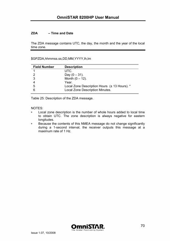
OmniSTAR 8200HP User Manual
Issue 1.07, 10/2008
70
ZDA – Time and Date
The ZDA message contains UTC, the day, the month and the year of the local time zone.
$GPZDA,hhmmss.ss,DD,MM,YYYY,lh,lm
Field Number Description 1 UTC. 2 Day (0 – 31). 3 Month (0 – 12). 4 Year. 5 Local Zone Description Hours (± 13 Hours). * 6 Local Zone Description Minutes.
Table 25: Description of the ZDA message.
NOTES: ∗ Local zone description is the number of whole hours added to local time
to obtain UTC. The zone description is always negative for eastern longitudes.
∗ Because the contents of this NMEA message do not change significantly during a 1-second interval, the receiver outputs this message at a maximum rate of 1 Hz.
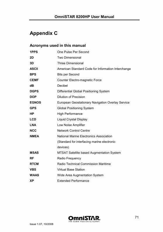
OmniSTAR 8200HP User Manual
Issue 1.07, 10/2008
71
Appendix C
Acronyms used in this manual 1PPS One Pulse Per Second
2D Two Dimensional
3D Three Dimensional
ASCII American Standard Code for Information Interchange
BPS Bits per Second
CEMF Counter Electro-magnetic Force
dB Decibel
DGPS Differential Global Positioning System
DOP Dilution of Precision
EGNOS European Geostationary Navigation Overlay Service
GPS Global Positioning System
HP High Performance
LCD Liquid Crystal Display
LNA Low Noise Amplifier
NCC Network Control Centre
NMEA National Marine Electronics Association
(Standard for interfacing marine electronic
devices)
MSAS MTSAT Satellite based Augmentation System
RF Radio Frequency
RTCM Radio Technical Commission Maritime
VBS Virtual Base Station
WAAS Wide Area Augmentation System
XP Extended Performance
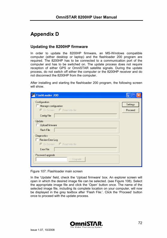
OmniSTAR 8200HP User Manual
Issue 1.07, 10/2008
72
Appendix D
Updating the 8200HP firmware In order to update the 8200HP firmware, an MS-Windows compatible computer (either desktop or laptop) and the flashloader 200 program are required. The 8200HP has to be connected to a communication port of the computer and has to be switched on. The update process does not require reception of either GPS or OmniSTAR satellite signals. During the update process, do not switch off either the computer or the 8200HP receiver and do not disconnect the 8200HP from the computer. After installing and starting the flashloader 200 program, the following screen will show.
Figure 107: Flashloader main screen
In the ‘Update’ field, check the ‘Upload firmware’ box. An explorer screen will open in which the desired image file can be selected. (see Figure 108). Select the appropriate image file and click the ‘Open’ button once. The name of the selected image file, including its complete location on your computer, will now be displayed in the grey textbox after ‘Flash File:’. Click the ‘Proceed’ button once to proceed with the update process.
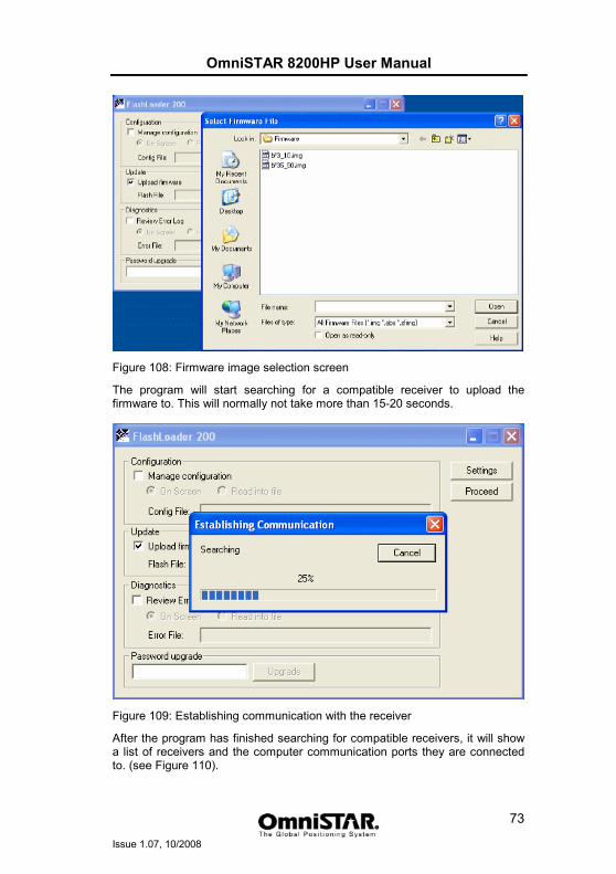
OmniSTAR 8200HP User Manual
Issue 1.07, 10/2008
73
Figure 108: Firmware image selection screen
The program will start searching for a compatible receiver to upload the firmware to. This will normally not take more than 15-20 seconds.
Figure 109: Establishing communication with the receiver
After the program has finished searching for compatible receivers, it will show a list of receivers and the computer communication ports they are connected to. (see Figure 110).
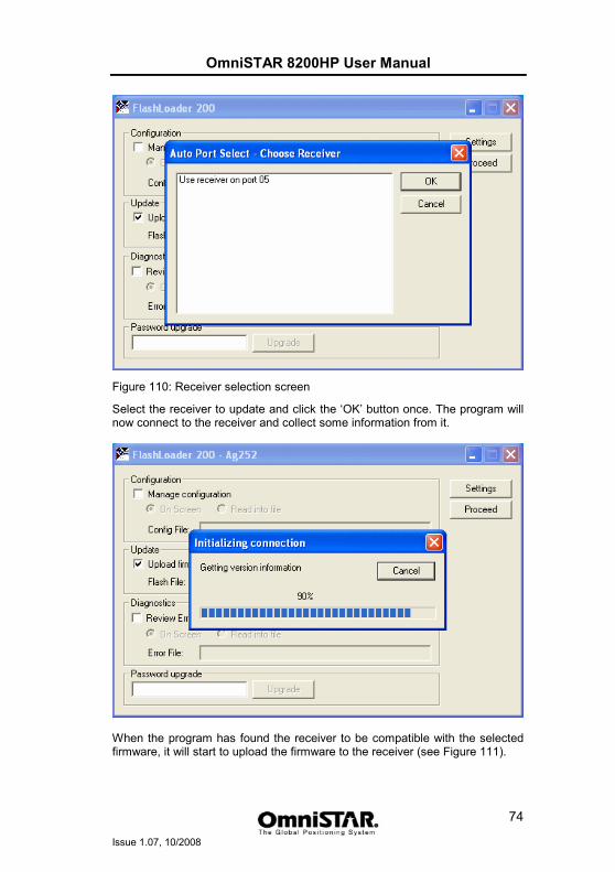
OmniSTAR 8200HP User Manual
Issue 1.07, 10/2008
74
Figure 110: Receiver selection screen
Select the receiver to update and click the ‘OK’ button once. The program will now connect to the receiver and collect some information from it.
When the program has found the receiver to be compatible with the selected firmware, it will start to upload the firmware to the receiver (see Figure 111).
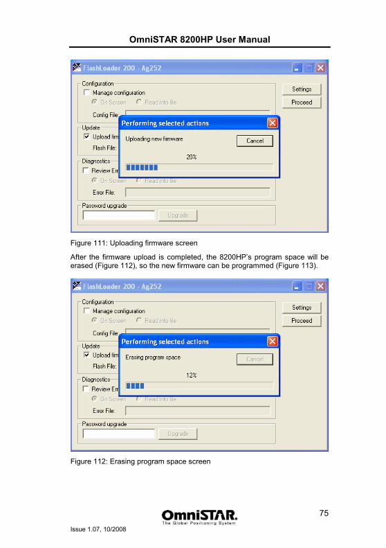
OmniSTAR 8200HP User Manual
Issue 1.07, 10/2008
75
Figure 111: Uploading firmware screen
After the firmware upload is completed, the 8200HP’s program space will be erased (Figure 112), so the new firmware can be programmed (Figure 113).
Figure 112: Erasing program space screen
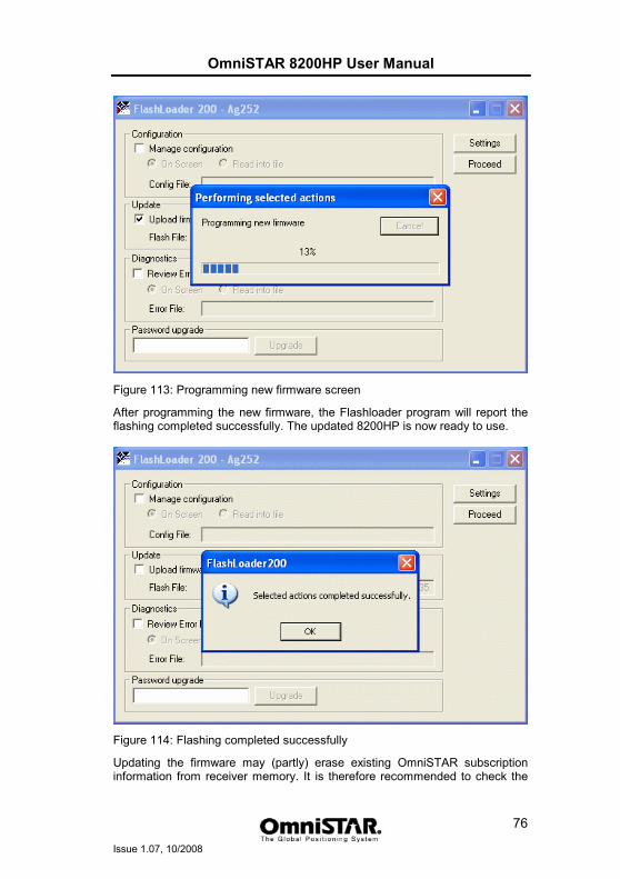
OmniSTAR 8200HP User Manual
Issue 1.07, 10/2008
76
Figure 113: Programming new firmware screen
After programming the new firmware, the Flashloader program will report the flashing completed successfully. The updated 8200HP is now ready to use.
Figure 114: Flashing completed successfully
Updating the firmware may (partly) erase existing OmniSTAR subscription information from receiver memory. It is therefore recommended to check the

OmniSTAR 8200HP User Manual
Issue 1.07, 10/2008
77
subscription end dates (see Figure 29 on page 26 and Figure 37 on page 28) after each firmware upgrade.
OmniSTAR 8200HP User Manual
Issue 1.07, 10/2008
78
Appendix E
OmniSTAR reference stations For its satellite based DGPS service, OmniSTAR uses correction data from a number of reference stations distributed all over the globe. The most recent map can be found on the internet: See http://www.surveyplanner.com
OmniSTAR 8200HP User Manual
Issue 1.07, 10/2008
79
Appendix F
Receiver Service Procedure If an OmniSTAR receiver unit fails to perform, contact the OmniSTAR office within the region, after following the procedural checks. We wish to hear about frequently experienced problems and your assistance will help by copying the form on the next page, filling in the details requested and faxing or mailing the form to the OmniSTAR office for on-forwarding to Product Marketing. The most common problems are interfacing, and usually occur at installation time. If you have an interfacing connection not covered in this manual we would like to assist you and produce another technical bulletin that may assist other users in the future. If a problem appears that you think may be caused by a system performance problem, contact the OmniSTAR office in your region for any system aberrations that may have been experienced. We are sensitive to our customers’ needs and we want to assure specified system performance at all times. There could, however, be situations where conditions are below par, such as fringe area operations, radio communication disturbance etc., and, as OmniSTAR receiver monitors the system performance continuously, these conditions would be noted.
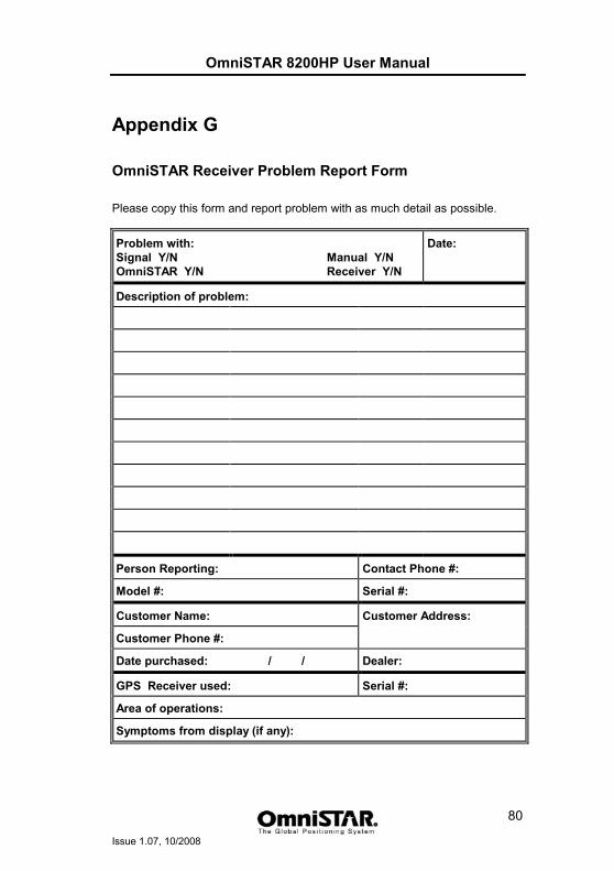
OmniSTAR 8200HP User Manual
Issue 1.07, 10/2008
80
Appendix G
OmniSTAR Receiver Problem Report Form Please copy this form and report problem with as much detail as possible.
Problem with: Signal Y/N Manual Y/N OmniSTAR Y/N Receiver Y/N
Date:
Description of problem:
Person Reporting: Contact Phone #:
Model #: Serial #:
Customer Name: Customer Address:
Customer Phone #:
Date purchased: / / Dealer:
GPS Receiver used: Serial #:
Area of operations:
Symptoms from display (if any):

OmniSTAR 8200HP User Manual
Issue 1.07, 10/2008
81
User Notes