Embed Size (px)
Citation preview
8/16/2002
1
Digital Transmission
Key Learning Points
• Fundamentals of Voice Digitization
• Pulse Code Modulation
• Quantification Noise
• Multiplexed Digital Lines
8/16/2002
2
2.5.2 Digital Leased Circuits (from public carriers)
- supports high level of inter-site traffic, generally more expensive than modem based service
- provides direct digital connection between DTE’s- basis of most private data & voice networks
goal: understand organization & capacity of digital
networks
Digital switching & transmission for voice & data used in most public carrier networks
• Eliminates Need for Modem – Voice data must be ‘digitized’
• ISDN: Network that allows Transmission of voice & data
• Public Carriers leased digital circuit rates from kbps..100’sMbps - digital circuits must co-exist with other circuits for inter-
change traffic
8/16/2002
3
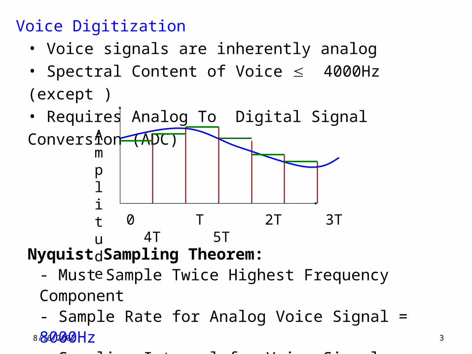
Voice Digitization• Voice signals are inherently analog • Spectral Content of Voice 4000Hz (except ) • Requires Analog To Digital Signal Conversion (ADC)
Nyquist Sampling Theorem: - Must Sample Twice Highest Frequency Component- Sample Rate for Analog Voice Signal = 8000Hz - Sampling Interval for Voice Signal = 0.125 ms
0 T 2T 3T 4T 5T
Amplitude
8/16/2002
4
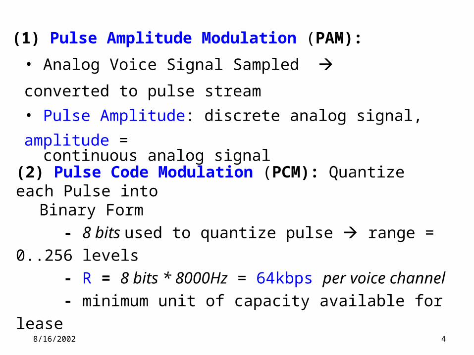
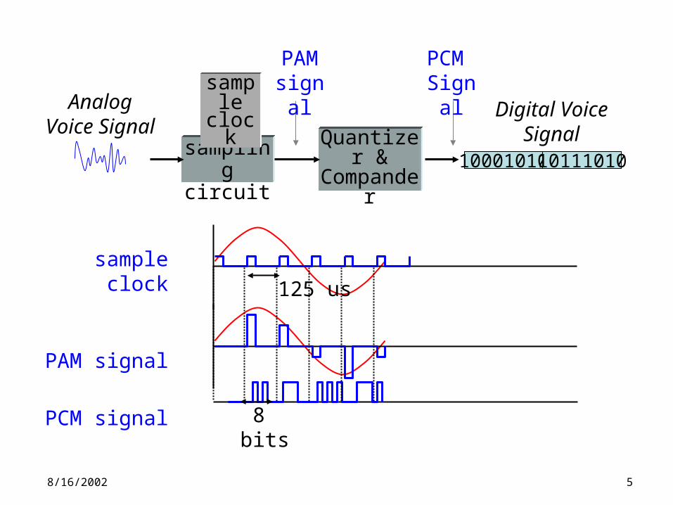
(1) Pulse Amplitude Modulation (PAM):
• Analog Voice Signal Sampled converted to pulse stream
• Pulse Amplitude: discrete analog signal, amplitude = continuous analog signal
(2) Pulse Code Modulation (PCM): Quantize each Pulse into Binary Form
- 8 bits used to quantize pulse range = 0..256 levels
- R = 8 bits * 8000Hz = 64kbps per voice channel
- minimum unit of capacity available for lease
8/16/2002
5
8 bits
125 us
sample clock
PAM signal
PCM signal
Digital Voice Signal
sampling circuit
Quantizer & Compander
sampleclock
PCM Signal
PAMsignal
Analog Voice Signal
10001010 10111010
8/16/2002
6
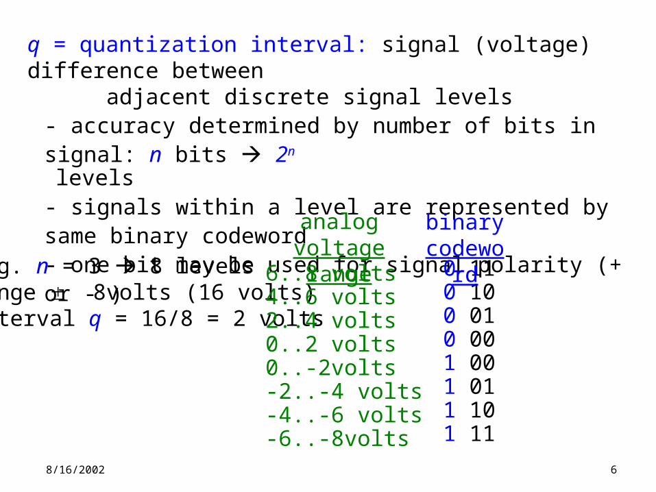
q = quantization interval: signal (voltage) difference between adjacent discrete signal levels
- accuracy determined by number of bits in signal: n bits 2n levels- signals within a level are represented by same binary codeword- one bit may be used for signal polarity (+ or - )
e.g. n = 3 8 levelsrange 8volts (16 volts)interval q = 16/8 = 2 volts
0 110 100 010 001 001 011 101 11
binary codeword
analogvoltage range
6..8 volts4..6 volts2..4 volts0..2 volts0..-2volts-2..-4 volts-4..-6 volts-6..-8volts
8/16/2002
7
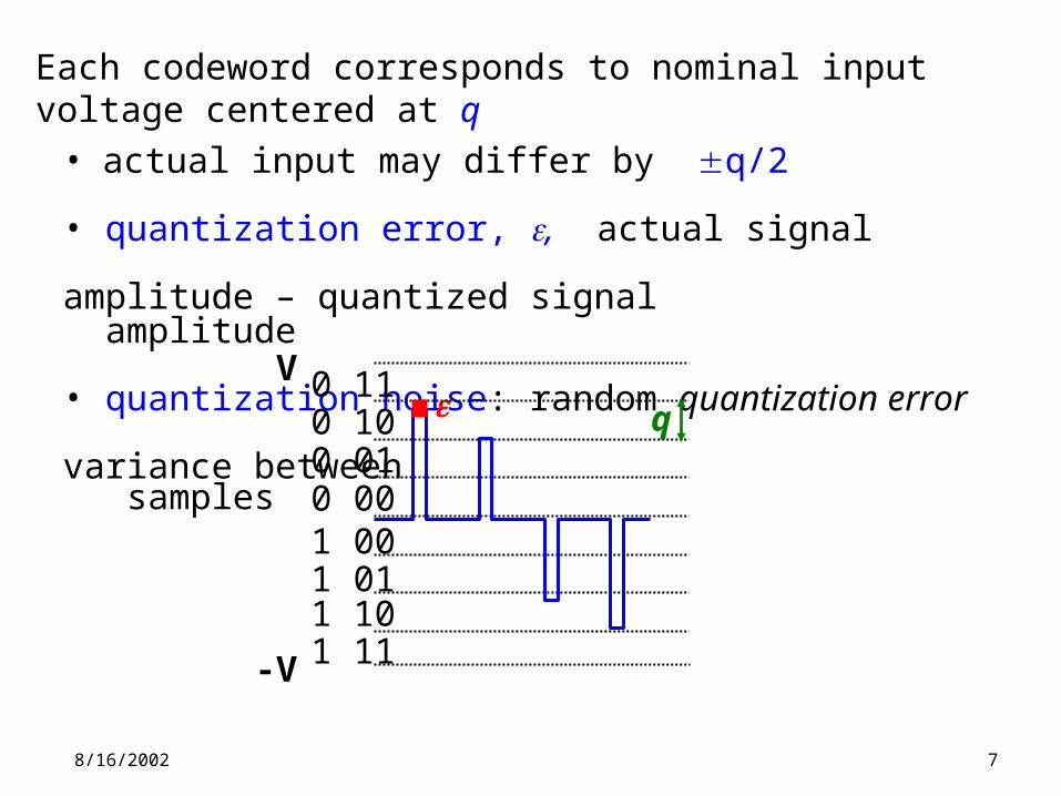
Each codeword corresponds to nominal input voltage centered at q • actual input may differ by q/2
• quantization error, , actual signal amplitude – quantized signal amplitude
• quantization noise: random quantization error variance between samples
0 110 100 010 001 001 011 101 11
q
V
-V
8/16/2002
8
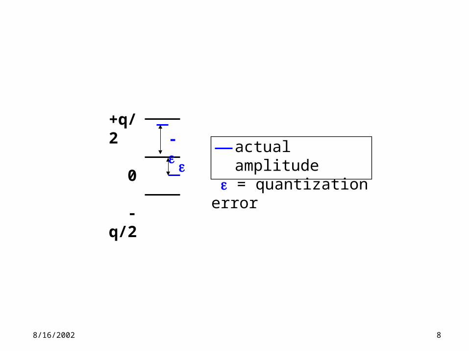
actual amplitude = quantization error
+q/2
0
-q/2
-
8/16/2002
9
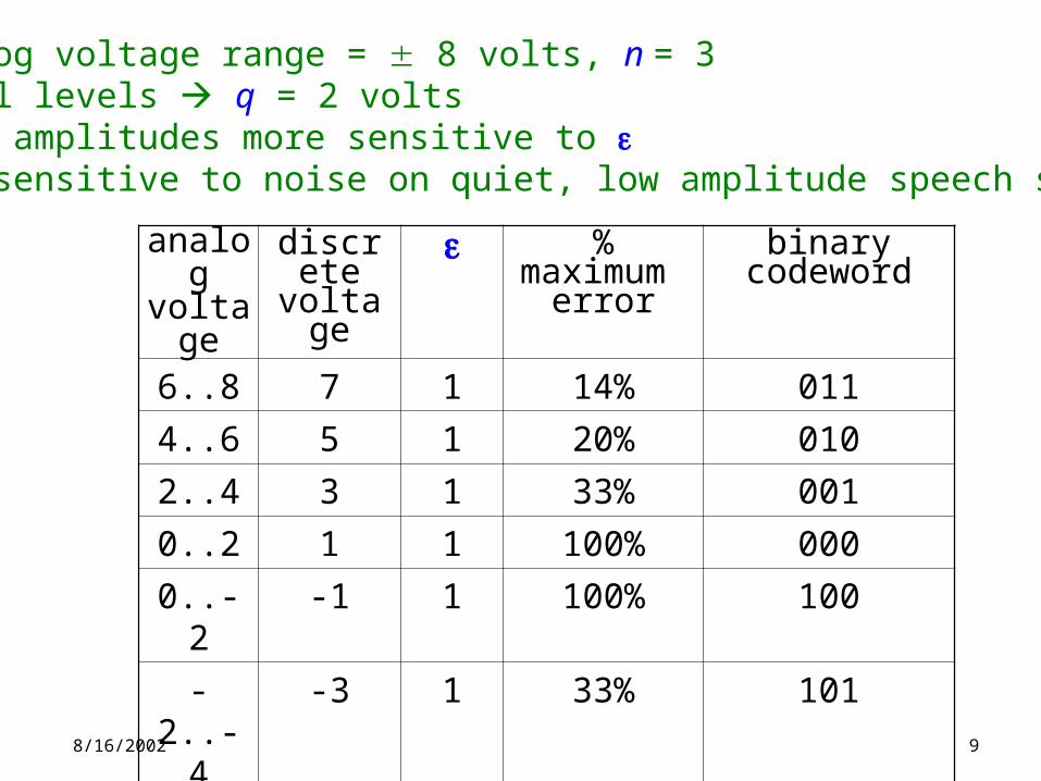
analog voltage
discrete voltage
% maximum error
binary codeword
6..8 7 1 14% 011
4..6 5 1 20% 010
2..4 3 1 33% 001
0..2 1 1 100% 000
0..-2 -1 1 100% 100
-2..-4 -3 1 33% 101
-4..-6 -5 1 20% 110
-6..-8 -7 1 14% 111
e.g. analog voltage range = 8 volts, n = 3• 8 signal levels q = 2 volts• smaller amplitudes more sensitive to • ear is sensitive to noise on quiet, low amplitude speech signals
8/16/2002
10
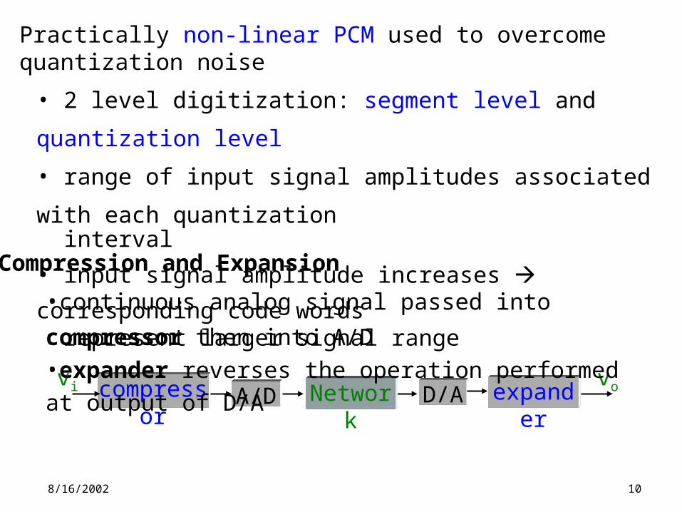
Practically non-linear PCM used to overcome quantization noise
• 2 level digitization: segment level and quantization level
• range of input signal amplitudes associated with each
quantization interval
• input signal amplitude increases corresponding code words represent larger signal range
vovi compressor expanderA/D D/ANetwork
•continuous analog signal passed into compressor then into A/D•expander reverses the operation performed at output of D/A
Compression and Expansion
8/16/2002
11
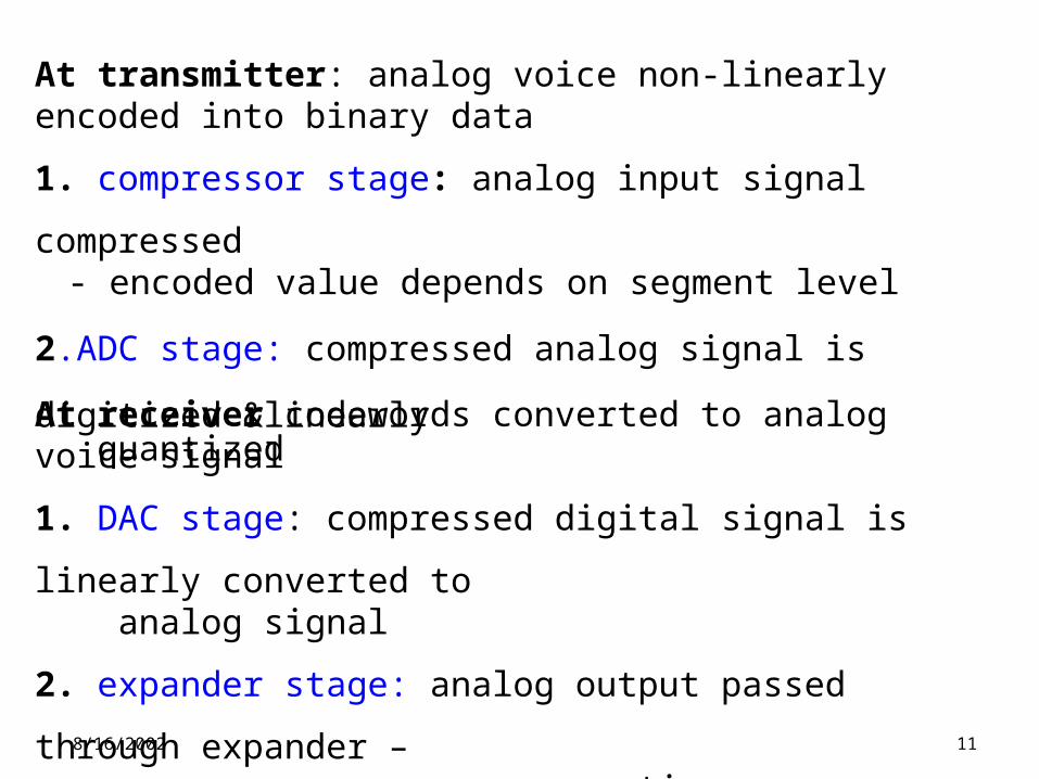
At transmitter: analog voice non-linearly encoded into binary data
1. compressor stage: analog input signal compressed - encoded value depends on segment level
2.ADC stage: compressed analog signal is digitized &linearly quantized
At receiver codewords converted to analog voice signal
1. DAC stage: compressed digital signal is linearly converted to analog signal
2. expander stage: analog output passed through expander – reverses compressor operation
8/16/2002
12
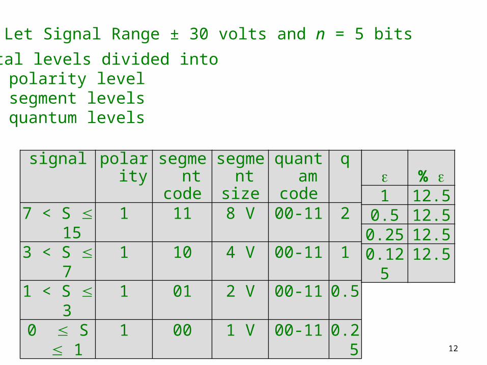
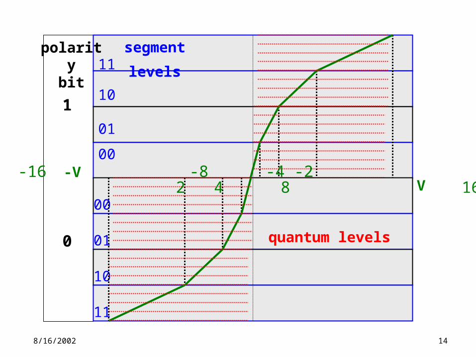
e.g. Let Signal Range ± 30 volts and n = 5 bits
32 total levels divided into• 1 polarity level• 2 segment levels• 2 quantum levels
signal polarity segmentcode
segment size
quantamcode
q
7 < S 15
1 11 8 V 00-11 2
3 < S 7 1 10 4 V 00-11 11 < S 3 1 01 2 V 00-11 0.50 S 1 1 00 1 V 00-11 0.25
% 1 12.5
0.5 12.50.25 12.50.125 12.5
8/16/2002
13
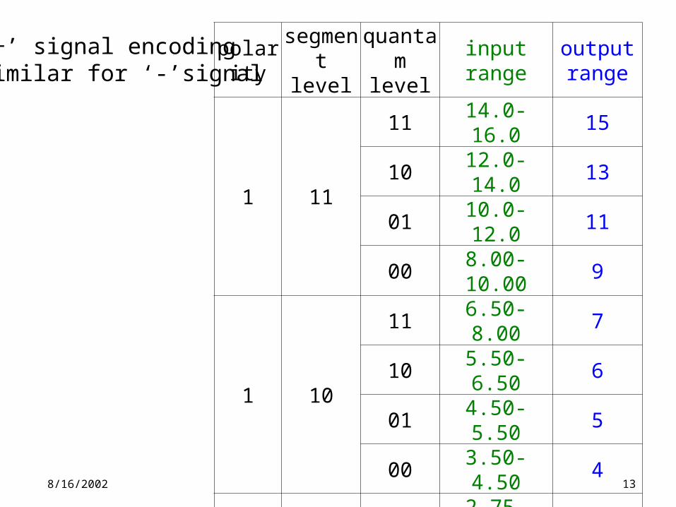
polaritysegment
levelquantam
levelinput range
output range
1 11
11 14.0-16.0 1510 12.0-14.0 1301 10.0-12.0 1100 8.00-10.00 9
1 10
11 6.50-8.00 710 5.50-6.50 601 4.50-5.50 500 3.50-4.50 4
1 01
11 2.75-3.50 3.010 2.25-2.75 2.501 1.75-2.25 2.000 1.25-1.75 1.5
1 00
11 0.875-1.25 1.010 0.625-0.875 0.7501 0.375-0.625 0.5000 0.00-0.375 0.25
• ‘+’ signal encoding• similar for ‘-’signal
8/16/2002
14
0
1
11
10
01
00
00
01
10
11
polaritybit
segment levels
quantum levels
V-16 -8 -4 -2
2 4 8 16-V
8/16/2002
15
PCM codecs (coder/decoder)• older codecs operated as above• newer codecs use 2 digital compression/expansion techniques
u-law: (N. America, Japan)A-law: (ITU-T)
- similar in principal to companding-expansion- conversion needed when using leased & switched circuits that span continents
- necessary only for voice
8/16/2002
16
Multiplexing (MUX)
Link Exchange Circuits: T1, T3, E1…- carry multiple calls concurrently- TDM Used: multiple digital signals assigned time slices
voice data: 8 bit sample @ 125us = 64kbps/ voice channel
control overhead: (i) start of frame (frame synchronization)(ii) call set-up (signaling)
8/16/2002
17
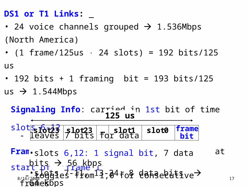
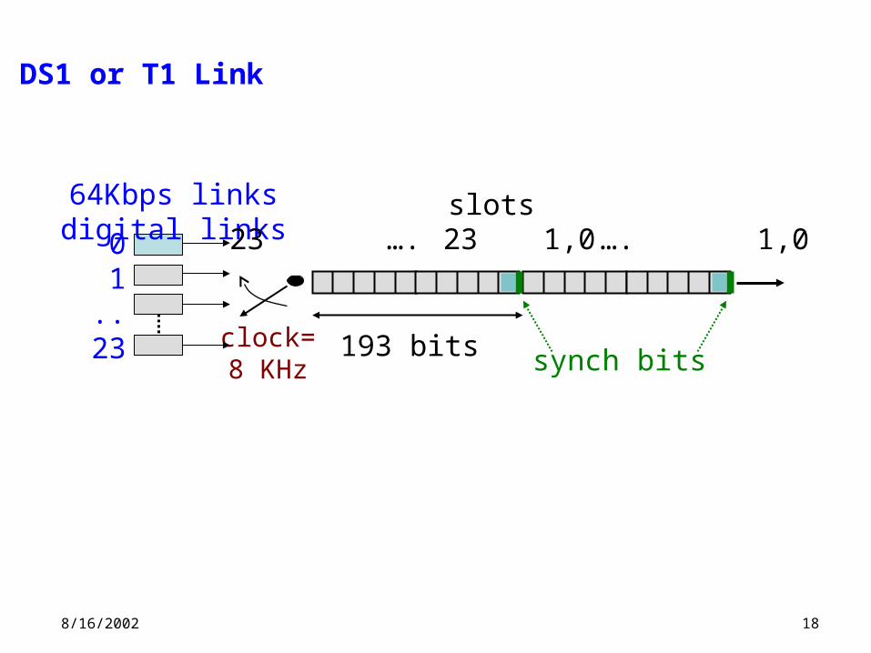
DS1 or T1 Links:
• 24 voice channels grouped 1.536Mbps (North America)
• (1 frame/125us 24 slots) = 192 bits/125 us
• 192 bits + 1 framing bit = 193 bits/125 us 1.544Mbps
Signaling Info: carried in 1st bit of time slots 6-12 - leaves 7 bits for data
Frame synchronization: bit (framing bit) at start of ‘frame 1’ - toggles from 1,0 for consecutive frames
•slots 6,12: 1 signal bit, 7 data bits 56 kbps•slots 7-11, 13-24: 8 data bits 64 kbps
slot 23 slot 23 … slot 1 slot 0 frame bit
125 us
8/16/2002
18
clock=8 KHz
64Kbps links digital links
01..
23
23 …. 1,0
193 bits
23 …. 1,0
synch bits
slots
DS1 or T1 Link
8/16/2002
19
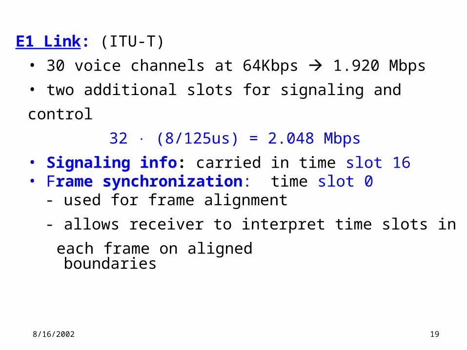
E1 Link: (ITU-T)
• 30 voice channels at 64Kbps 1.920 Mbps
• two additional slots for signaling and control
32 (8/125us) = 2.048 Mbps
• Signaling info: carried in time slot 16• Frame synchronization: time slot 0
- used for frame alignment
- allows receiver to interpret time slots in each frame on aligned boundaries
8/16/2002
20
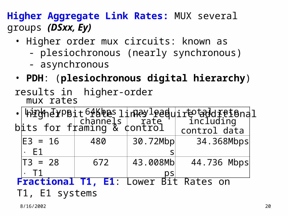
Fractional T1, E1: Lower Bit Rates on T1, E1 systems
Higher Aggregate Link Rates: MUX several groups (DSxx, Ey)• Higher order mux circuits: known as
- plesiochronous (nearly synchronous) - asynchronous
• PDH: (plesiochronous digital hierarchy) results in higher-order mux rates• higher bit rate links require additional bits for framing & control
Link Type 64Kbps channels
payload rate total rate including control data
E3 = 16 E1 480 30.72Mbps 34.368MbpsT3 = 28 T1 672 43.008Mbps 44.736 Mbps
8/16/2002
21
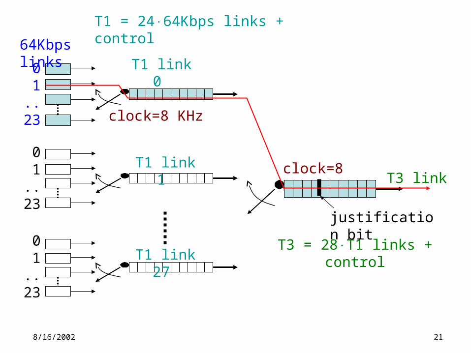
clock=8 KHz
64Kbps links
01..
23
T1 = 2464Kbps links + control
T1 link 0
01..
23
T1 link 1
01..
23
T1 link 27 T3 = 28T1 links + control
clock=8 KHzT3 link
justification bit
8/16/2002
22
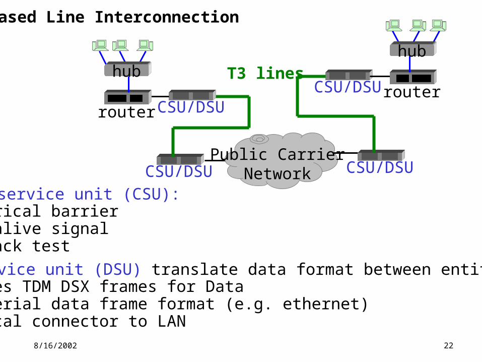
Leased Line Interconnection
channel service unit (CSU): •electrical barrier •keep alive signal•loopback test
data service unit (DSU) translate data format between entities•T1 uses TDM DSX frames for Data•LAN serial data frame format (e.g. ethernet)•physical connector to LAN
Public CarrierNetworkCSU/DSU CSU/DSU
CSU/DSUrouter
hubCSU/DSU router
hubT3 lines