Embed Size (px)
DESCRIPTION
ABB DCS
Citation preview

Having a reliable single source of system information not only assures a high level of data consistency, but also provides for excellent engineering effi ciency and quality throughout the entire life cycle of the automation system. By offering a consistent engineering environment, the System 800xA promotes a consistent fl ow of information across all engineering stages — from designing to installing and commissioning up to operation and maintenance. The integrated engineering environment assures one-time data input and a very high level of data integrity and up-to-datedness.Thanks to the system’s scalable architecture, additional functions and workplaces can be integrated or remotely interfaced via the Internet or Intranet without diffi culty. Naturally, the system con-forms with the applicable control-engineering security concepts based on the BSI*) requirements and recommendations.*) Federal Offi ce for IT Security
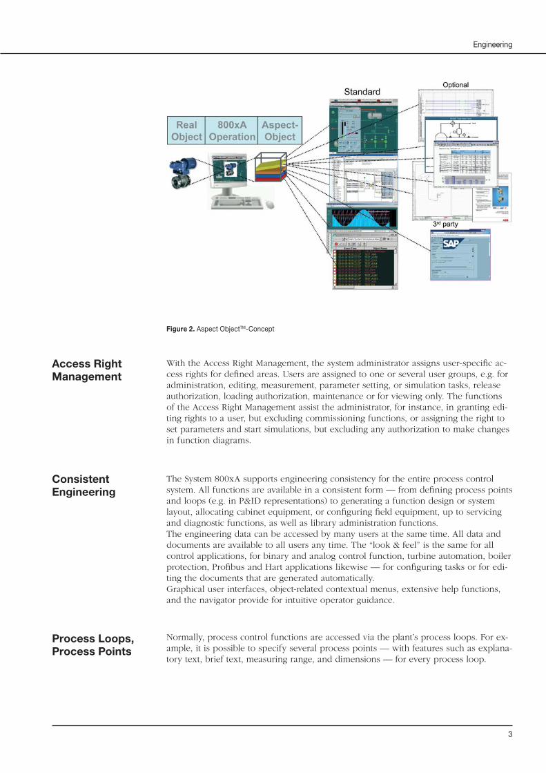
External information can be imported for reuse and is automa-tically subjected to plausibility checks and change identifi cation procedures. By integrating third-party applications, users can call up any type of information from a context-sensitive envi-ronment. With the patented Aspect Object philosophy of the System 800xA, workplaces can be personalized for users and customized to permit access to any information within or outside the process control system. For instance, the system fea-tures allow users to call up function diagram for any given func-tion, directly from the operating screen of an System 800xA, without having to go through additional confi guration activities.
IndustrialIT System 800xAEngineering
Overview
Features and Benefi ts
■ Integrated Engineering Environ-ment: The engineering activities for the components of the extended au-tomation system — ranging from fi eld instrumentation to plant operation applications — are supported throug-hout the components’ entire life cycle, thus assuring a consistent engineering philosophy for all activities and system components.
■ Intuitive Environment: Graphical user interfaces, object-related contex-tual menus and extensive help func-tions provide for advanced intuitive operator guidance.
■ Graphical Function Design: Engineering versus programming.
Graphical design features are availa-ble for all I&C applications — from fi eld instrumentation to process logic — and create more clarity and effi ci-ency for engineering and maintenance tasks.
■ Continual Improvement through Reusable Solutions: Best-practice standards can be reproduced and adjusted quickly to allow for special conditions, while requiring very little engineering and validation input.
■ Consistent Forward Documenta-tion: Thanks to a consistent for-ward documentation concept, which includes a general change and revision management, the latest versions of documents are available to users on demand.
■ Operator Graphics: Object-specifi c operator graphics, such as faceplates and icons, are generated automatically with the help of predefi ned elements and adapted to the given I&C applica-tion.
■ Integrated Documentation: Users can intuitively access the documenta-tion available for any components and devices involved.

2
IndustrialIT System 800xA
Introduction
Figure 1. System 800xA Engineering is an integral part of the system.
System 800xA Engineering offers new ways of accessing information from a single engineering workplace, covering the entire automation project, including all tasks of planning, data collection, confi guration management, commissioning, and operating. The integrated environment is laid out for the entire engineering life cycle and sub-stantially minimizes the cost of system implementation. For example, highly qualifi ed staff can be relieved of routine tasks and are therefore free to perform truly value-added activities and focus on quality aspects.
Through the use of ABB’s patented Aspect Object technology for IndustrialIT appli-cations, the System 800xA supports nearly seamless integration of plant and control system data. The System 800xA serves as a portal to all system information that is needed for installation, operation and maintenance. The portal comprises all informa-tion and data, which usually needs to be retrieved from different applications, and has them available on the desktop, suitable for intuitive operator navigation. This integra-ted environment defi nitely minimizes the commissioning times, reduces the number of maintenance tasks and provides for short turn-around times regarding engineering changes, without any loss of data consistency or performance quality.
System Architecture
3
Engineering
ConsistentEngineering
Access Right Management
With the Access Right Management, the system administrator assigns user-specifi c ac-cess rights for defi ned areas. Users are assigned to one or several user groups, e.g. for administration, editing, measurement, parameter setting, or simulation tasks, release authorization, loading authorization, maintenance or for viewing only. The functions of the Access Right Management assist the administrator, for instance, in granting edi-ting rights to a user, but excluding commissioning functions, or assigning the right to set parameters and start simulations, but excluding any authorization to make changes in function diagrams.
The System 800xA supports engineering consistency for the entire process control system. All functions are available in a consistent form — from defi ning process points and loops (e.g. in P&ID representations) to generating a function design or system layout, allocating cabinet equipment, or confi guring fi eld equipment, up to servicing and diagnostic functions, as well as library administration functions. The engineering data can be accessed by many users at the same time. All data and documents are available to all users any time. The “look & feel” is the same for all control applications, for binary and analog control function, turbine automation, boiler protection, Profi bus and Hart applications likewise — for confi guring tasks or for edi-ting the documents that are generated automatically.Graphical user interfaces, object-related contextual menus, extensive help functions, and the navigator provide for intuitive operator guidance.
Process Loops, Process Points
Figure 2. Aspect ObjectTM-Concept
Normally, process control functions are accessed via the plant’s process loops. For ex-ample, it is possible to specify several process points — with features such as explana-tory text, brief text, measuring range, and dimensions — for every process loop.
4
IndustrialIT System 800xA
Of course, the system supports different item designation codes, e.g. the ISO 3511-1 and DIN 6779-10 standards (the KKS power plant designation code). Process data sheets provide detailed descriptions of the process points.The hierarchical function and system structures are based on function units and the defi ned plant areas. The process-point and actuator lists are generated from process-point-specifi c data. The process- and function-specifi c interrelations between process points are represented in control engineering P&I diagrams, and in overview and area diagrams.
With its centralized and redundant server concept, the System 800xA system offers a fl exible and scalable engineering environment where data are made available either to users interfaced on-plant, or to decentralized, off-plant engineering environments.Thanks to the multi-user environment, a wide variety of engineering tasks can be per-formed at different locations at the same time.
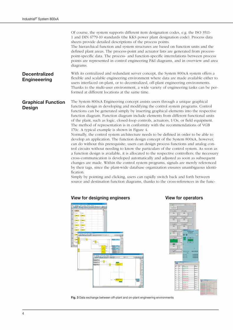
The System 800xA Engineering concept assists users through a unique graphical function design in developing and modifying the control system programs. Control functions can be generated simply by inserting graphical elements into the respective function diagram. Function diagram include elements from different functional units of the plant, such as logic, closed-loop controls, actuators, I/Os, or fi eld equipment. The method of representation is in conformity with the recommendations of VGB 170c. A typical example is shown in Figure 4.Normally, the control system architecture needs to be defi ned in order to be able to develop an application. The function design concept of the System 800xA, however, can do without this prerequisite; users can design process functions and analog con-trol circuits without needing to know the particulars of the control system. As soon as a function design is available, it is allocated to the respective controllers; the necessary cross-communication is developed automatically and adjusted as soon as subsequent changes are made. Within the control system programs, signals are merely referenced by their tags, since the plant-wide database organization ensures unambiguous identi-fi cation. Simply by pointing and clicking, users can rapidly switch back and forth between source and destination function diagrams, thanks to the cross-references in the func-
Graphical Function Design
Decentralized Engineeering
Fig. 3 Data exchange between off-plant and on-plant engineering environments
View for designing engineers View for operators
5
Engineering
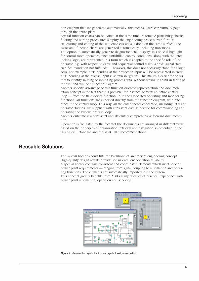
tion diagram that are generated automatically; this means, users can virtually page through the entire plant.Several function charts can be edited at the same time. Automatic plausibility checks, fi ltering and sorting procedures simplify the engineering process even further.Structuring and editing of the sequence cascades is done on the same surface. The associated function charts are generated automatically, including transitions.The option to automatically generate diagnostic detail displays is a special highlight for control room operators, since unfulfi lled control conditions, along with the inter-locking logic, are represented in a form which is adapted to the specifi c role of the operator, e.g. with respect to drive and sequential control tasks. A “red” signal state signifi es “condition not fulfi lled” — however, this does not necessary stand for a logic zero. For example: a “1” pending at the protection input will be represented in “red”; a “1” pending at the release input is shown in “green”. This makes it easier for opera-tors to identify missing or inhibiting process data, without having to think in terms of the “1s” and “0s” of a function diagram. Another specifi c advantage of this function-oriented representation and documen-tation concept is the fact that it is possible, for instance, to view an entire control loop — from the fi eld device function up to the associated operating and monitoring functions. All functions are exported directly from the function diagram, with refe-rence to the control loop. This way, all the components concerned, including I/Os and operator stations, are supplied with consistent data as needed for commissioning and operating the various process loops.Another outcome is a consistent and absolutely comprehensive forward documenta-tion.Operation is facilitated by the fact that the documents are arranged in different views, based on the principles of organization, retrieval and navigation as described in the IEC 61346-1 standard and the VGB 170 c recommendations.
The system libraries constitute the backbone of an effi cient engineering concept. High-quality design results provide for an excellent operation reliability.A special library contains consistent and coordinated elements which meet specifi c power plant requirements — ranging from signal coupling to automation and opera-ting functions. The elements are automatically imported into the system.This concept greatly benefi ts from ABB’s many decades of practical experience with power plant automation, operation and servicing.
Reusable Solutions
Figure 4. Macro editor, symbol editor, and symbol assignment editor

6
IndustrialIT System 800xA
The libraries are extended on a continual basis, depending on the given requirements. In order to be able to effi ciently process their projects, users are also offered ad-ditional tools for generating and editing tasks. For instance, not only is it possible to copy function charts, users can actually duplicate entire data hierarchies, e.g. for function units or defi ned plant areas.
The control system structure, the allocation of station components and the net-work structure are developed on the same design surface. Comprehensive libraries with integrated plausibility checks help create problem-free and simple procedures, while supporting a continually updated system overview.
Figure 5. Allocation of cabinet equipment, system overview, defi nition of stations and islands
Devices and electronic modules are allocated to their slots in the graphic represen-tation of the cabinet equipment. The defi nitions regarding the level of module redundancy are applied automatically.
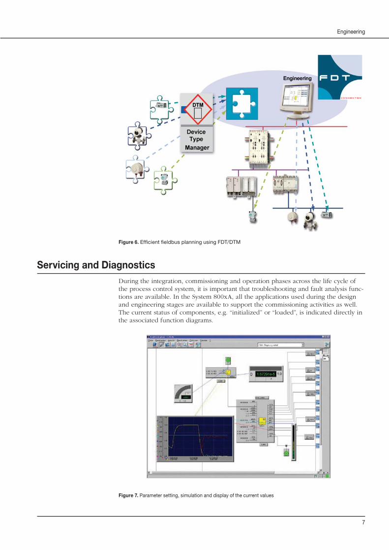
The System 800xA supports the true integration of fi eld instruments via PROFIBUSor HART. The Field Device Tool (FDT) supports confi guring, commissioning and maintenance tasks for PROFIBUS fi eld instrumentation, using Device Type Managers (DTM) which — similar to printer drivers in a Microsoft environment — make the respective fi eld devices known to the overall process control system and thus make them accessible to confi guration procedures and diagnostics.The DTMs can be accessed, for instance, via the function diagram, the system over-view, or the location structure.
System Design
Fieldbus Planning
7
Engineering
Figure 6. Effi cient fi eldbus planning using FDT/DTM
During the integration, commissioning and operation phases across the life cycle of the process control system, it is important that troubleshooting and fault analysis func-tions are available. In the System 800xA, all the applications used during the design and engineering stages are available to support the commissioning activities as well. The current status of components, e.g. “initialized” or “loaded”, is indicated directly in the associated function diagrams.
Servicing and Diagnostics
Figure 7. Parameter setting, simulation and display of the current values
8
IndustrialIT System 800xA
Documentation and InformationSystem
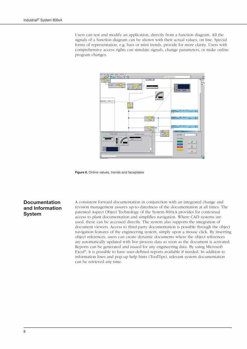
Users can test and modify an application, directly from a function diagram. All the signals of a function diagram can be shown with their actual values, on line. Special forms of representation, e.g. bars or mini trends, provide for more clarity. Users with comprehensive access rights can simulate signals, change parameters, or make online program changes.
Figure 8. Online values, trends and faceplates
A consistent forward documentation in conjunction with an integrated change and revision management assures up-to-datedness of the documentation at all times. The patented Aspect Object Technology of the System 800xA provides for contextual access to plant documentation and simplifi es navigation. Where CAD systems are used, these can be accessed directly. The system also supports the integration of document viewers. Access to third-party documentation is possible through the object navigation features of the engineering system, simply upon a mouse click. By inserting object references, users can create dynamic documents where the object references are automatically updated with live process data as soon as the document is activated. Reports can be generated and issued for any engineering data. By using Microsoft Excel®, it is possible to have user-defi ned reports available if needed. In addition to information lines and pop-up help hints (ToolTips), relevant system documentation can be retrieved any time.
9
Engineering
Integration of Process Engineering Tools
DataManagement
Scalable Toolkit
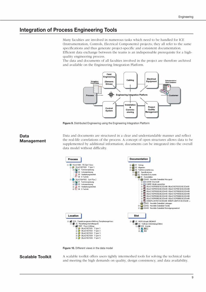
Many faculties are involved in numerous tasks which need to be handled for ICE (Instrumentation, Controls, Electrical Components) projects; they all refer to the same specifi cations and thus generate project-specifi c and consistent documentation.Effi cient data exchange between the teams is an indispensable prerequisite for a high-quality engineering process. The data and documents of all faculties involved in the project are therefore archived and available on the Engineering Integration Platform.
Figure 9. Distributed Engineering using the Engineering Integration Platform
Data and documents are structured in a clear and understandable manner and refl ect the real-life correlations of the process. A concept of open structures allows data to be supplemented by additional information; documents can be integrated into the overall data model without diffi culty.
Figure 10. Different views in the data model
A scalable toolkit offers users tightly intermeshed tools for solving the technical tasks and meeting the high demands on quality, design consistency, and data availability.
10
IndustrialIT System 800xA
Bulk Data Import
Field Components
Control Systems
Project Documentation
Project Quality Management
Electrical Components
Cabling
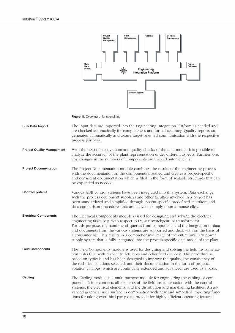
Figure 11. Overview of functionalities
The input data are imported into the Engineering Integration Platform as needed and are checked automatically for completeness and formal accuracy. Quality reports are generated automatically and assure target-oriented communication with the respective process partners.
With the help of steady automatic quality checks of the data model, it is possible to analyze the accuracy of the plant representation under different aspects. Furthermore, any changes in the numbers of components are tracked automatically. The Project Documentation module combines the results of the engineering process with the documentation on the components installed and creates a project-specifi c and consistent documentation which is fi led in the form of scalable structures that can be expanded as needed.
Various ABB control systems have been integrated into this system. Data exchange with the process equipment suppliers and other faculties involved in a project has been standardized and simplifi ed through system-specifi c predefi ned interfaces and data comparison procedures that are activated simply upon a mouse click.
The Electrical Components module is used for designing and solving the electrical engineering tasks (e.g. with respect to LV, MV switchgear, or transformers). For this purpose, the handling of queries from components and the integration of data and documents from the various systems are supported and dealt with on the basis of a consumer list. This results in a comprehensive image of the entire auxiliary power supply system that is fully integrated into the process-specifi c data model of the plant.
The Field Components module is used for designing and solving the fi eld instrumenta-tion tasks (e.g. with respect to actuators and other fi eld devices). The procedure is based on typicals and has been designed to improve the quality, the consistency of the technical solutions selected, and their documentation in the form of projects. Solution catalogs, which are continually extended and advanced, are used as a basis.
The Cabling module is a multi-purpose module for engineering the cabling of com-ponents. It interconnects all elements of the fi eld instrumentation with the control systems, the electrical elements, and the distribution and marshalling facilities. An ad-vanced graphical user surface in combination with new and simplifi ed importing func-tions for taking-over third-party data provide for highly effi cient operating features.

11
Engineering
Process Visualization
Graphic Displays
Faceplates
Figure 12. Graphic representation of a circuit diagram
The graphic user interface of System 800xA Operations is based on the ActiveX® technology. Thanks to this technology, the system supports dynamic real-time status displays as well as hyperlinks in process graphics. The basic system incorporates an extensive library of more than 3800 ActiveX® elements for creating customized gra-phics. The graphics can include photographs, bit maps or graphics from systems of other vendors that are capable of supporting the ActiveX technology. For more information on the runtime graphics environment, please refer to the “System 800xA Operations Overview”.
Figure 13. Creating graphic displays for System 800xA Operations
The faceplates used in System 800xA Operations have a standardized look & feel, with three preconfi gured views being available. The standardized faceplate concept mini-mizes the confi guration time. Vital information is displayed to the user in a minimal view which takes up very little space on the screen. Both, the normal view and exten-ded view, provide additional and detail information and offer access to further data on tuning, alarm and diagnostic functions.
DEABB 1264 06 E
© Copyright 2006 ABB. All rights reserverd. NOTE: We reserve the right to make technical changes or modify the contents of this document without prior notice. With regard to purchase orders, the agreed particulars shall prevail. ABB does not accept any responsibility whatsoever for potential errors or possible lack of information in this document.We reserve all rights in this document and in the subject matter and illustrations contained therein. Any reproduction, disclosure to third parties or utilitzation of its contents – in whole or in parts – is forbidden without ABB’s prior written consent.
The IndustrialIT wordmark and all mentioned product names in the form XXXXXXIT, TURBOTROL® and EGATURN® are registered or pending trademarks of ABB. Windows XP®, Windows 2000®, EXCEL®, WORD® Explorer are registered trademarks of the Microsoft Corporation, USA.
ABB AGPower Technologies SystemsP.O. Box 10 03 5168128 MannheimGERMANYPhone: 0621 381-3000Fax: 0621 381-2645E-mail: [email protected]: http://www.abb.com/pt