Embed Size (px)
Citation preview

8000 SeriesGrade 1 exit device
Equia nestotatus enis 2015
LecestSunturOrem fugaEquia nestotatusDisciisi nisquissusNequisi VoloreptataeConsecumque soloribusIminveria volorum

dormakaba 8000 Grade 1 exit device
2
8000 Series Grade 1 exit devicesCertification & specificationsData & featuresOptionsANSI functionsOrdering guideHanding
Applications & listings Single doorsPair of doors with removable mullionsPair of doors
Exit devices 8300 exit device functions8300 strikes & minimum stile8400 exit device functions8400 strikes & minimum stileTrim ordering guideLever & knob stylesTrimCylinder specificationsAccessoriesElectrical functionsMullions
344566
777
89
101113131420202122
8000 SeriesGrade 1 exit device with deadlocking latch bolts
DORMA USA quality and environmental management systems in Reamstown, PA and Steeleville, IL are certified to ISO 9001:2008 and ISO 14001:2004.
dormakaba

8000 Series exit devices minimize forced entry while offering a low-cost solution to life safety requirements.
Certification• Certified/listed
to ANSI/BHMA 156.3, Grade 1 for exit devices.
• U.L. and C.U.L. listed under their continuing reinspection programs and conforms to standards U.L. 10C positive pressure testing.
• Complies with NFPA 101 life safety code. Fire rated devices comply with NFPA 80 fire doors and windows.
• Devices, trim, pulls, and levers comply with the Americans for Disabilities Act, 1994, and ICC A117.1 for accessible and usable buildings and facilities.
• Contributes to U.S. Green Building Council, LEED MR Credits 2.1, 4.1, 4.2, and 5.1.
• Listed with the California Department of Forestry and Fire Protection, Office of the State Fire Marshal.
• Hurricane code approved to Miami-Dade County Florida acceptance No. 06-912.04.
Specifications• All exit devices shall be
8000 Series rim, surface vertical rod or surface vertical rod “less bottom rod” devices.
• All device touchbars, rails, and integral parts shall be constructed of solid steel with ABS thermo-plastic end caps and covers.
• Non-labeled units to have hex-key dogging stan-dard.
• Fire rated versions shall be available for labeled applications.
• All surface vertical rod devices shall have pullman type latch bolts for the top latch with a round slide bolt bottom latch.
• All units shall offer trim options ranging from no trim, exit only blank trim, entrance by trim when touchbar is dogged, entrance when latch bolt is retracted by key, and entrance by lever set with a key to lock and unlock lever.
• Device touchbar, rail, and rods shall be available with a powder coated finish or base material stainless steel.
Optional specifications• Non-labeled devices to
have cylinder dogging. Mortise cylinder included.
• All surface vertical rod devices to have pullman type bottom latch bolt.
• All surface vertical rod devices to have extended top rod.
• All surface vertical rod devices to be available less bottom rod.
• Devices to have monitor switch in the touchbar to provide local and/or remote notification when the touchbar is de-pressed.
• Devices to have electric bolt retraction to provide remote access from the secure side of the door. Can also be used in conjunction with an automatic door operator.
• Devices to have latch monitor for monitoring the latch bolt status.
• Devices to have one of the following exit alarm options: battery powered exit alarm, battery powered exit alarm with a four minute reset, or direct wired exit alarm.
• Devices to use a glass lite shim kit to raise the device from the door surface and avoid glass lite molding.
• All labeled wood or composite door devices must use sex bolts.
Finishes
Exit device finishes• Aluminum: 689• Aluminum with SS
touchbar: 689 / 630 TB• Bronze: 691 (dull) or
695 (dark duranodic)• Black: 693• Gold: 696• Cle ar powder coating:
Specify P
Note: Covers and end caps are black ABS thermoplas-tic.
Trim finishes• Aluminum: 689• Bronze: 691 (dull) or 695
(dark duranodic)• Black: 693• Chrome: 626 (satin)• Gold: 696• Cle ar powder coating:
Specify P
WarrantyFor details, refer to Limited Warranty on our website at go.dormakaba.com/Terms-DA
8000 Series Certification & specifications
3
Certification & Specifications
dormakaba 8000 Grade 1 exit device
4
Data & features
Options
dormakaba
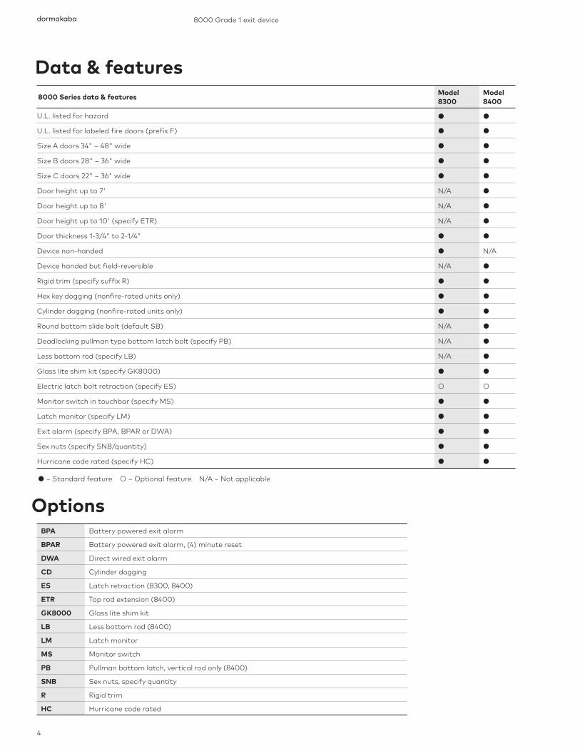
● – Standard feature ○ – Optional feature N/A – Not applicable
8000 Series data & features Model 8300
Model 8400
U.L. listed for hazard ● ●
U.L. listed for labeled fire doors (prefix F) ● ●
Size A doors 34" – 48" wide ● ●
Size B doors 28" – 36" wide ● ●
Size C doors 22" – 36" wide ● ●
Door height up to 7' N/A ●
Door height up to 8' N/A ●
Door height up to 10' (specify ETR) N/A ●
Door thickness 1-3/4" to 2-1/4" ● ●
Device non-handed ● N/A
Device handed but field-reversible N/A ●
Rigid trim (specify suffix R) ● ●
Hex key dogging (nonfire-rated units only) ● ●
Cylinder dogging (nonfire-rated units only) ● ●
Round bottom slide bolt (default SB) N/A ●
Deadlocking pullman type bottom latch bolt (specify PB) N/A ●
Less bottom rod (specify LB) N/A ●
Glass lite shim kit (specify GK8000) ● ●
Electric latch bolt retraction (specify ES) ○ ○
Monitor switch in touchbar (specify MS) ● ●
Latch monitor (specify LM) ● ●
Exit alarm (specify BPA, BPAR or DWA) ● ●
Sex nuts (specify SNB/quantity) ● ●
Hurricane code rated (specify HC) ● ●
BPA Battery powered exit alarm
BPAR Battery powered exit alarm, (4) minute reset
DWA Direct wired exit alarm
CD Cylinder dogging
ES Latch retraction (8300, 8400)
ETR Top rod extension (8400)
GK8000 Glass lite shim kit
LB Less bottom rod (8400)
LM Latch monitor
MS Monitor switch
PB Pullman bottom latch, vertical rod only (8400)
SNB Sex nuts, specify quantity
R Rigid trim
HC Hurricane code rated

ANSI functions
5
Data & features Options ANSI functions
ANSIfunction
Function description
Type 1 rim exit device
Type 2 surface vertical rod exit device
01 Exit Only – No Trim. 8300 or F8300 8400 or F8400
02 Entrance by trim when actuating bar is locked down.
83 00 × (trim) 8PDT / 8P02 / 8ODTP 8R02R / 8C02R PTS02 / PRS02
84 00 × (trim) 8PDT / 8P02 / 8ODTP 8R02R / 8C02R PTS02 / PRS02
03 Entrance by trim when latch bolt is retracted by key. Key removable only when locked.
83 00 or F8300 × (trim) 8P02 / 8O03 / 8P03 / 8O03P 8HK03 / 8HK03J / 8HR03 / 8HR03J / 8HC03 / 8HC03J / 8HG03 / 8HG03J 8K03 / 8K03J / 8R03 / 8R03J / 8C03 / 8C03J / 8G03 / 8G03J NPS03 / PTS03 / PRS03
84 00 or F8400 × (trim) 8P02 / 8O03 / 8P03 / 8O03P 8HK03 / 8HK03J / 8HR03 / 8HR03J/ 8HC03 / 8HC03J / 8HG03 / 8HG03J 8K03 / 8K03J / 8R03 / 8R03J / 8C03 / 8C03J / 8G03 / 8G03J NPS03 / PTS03 / PRS03
05 Entrance by thumbpiece. Key locks or unlocks thumbpiece.
83 00 or F8300 × (trim) HTS05 / HRS05
84 00 or F8400 × (trim) HTT05 / HRT05
06 Entrance by thumbpiece only when released by key. Key removable only when locked.
83 00 or F8300 × (trim) HTS06 / HRS06
84 00 or F8400 × (trim) HTT06 / HRT06
08 Entrance by lever or knob. Key locks or unlocks knob or lever.
83 00 or F8300 × (trim) 8HK08 / 8HK08J / 8HR08 / 8HR08J / 8HC08 / 8HC08J / 8HG08 / 8HG08J 8K08 / 8K08J / 8R08 / 8R08J / 8C08 / 8C08J / 8G08 / 8G08J
84 00 or F8400 × (trim) 8HK08 / 8HK08J / 8HR08 / 8HR08J / 8HC08 / 8HC08J / 8HG08 / 8HG08J 8K08 / 8K08J / 8R08 / 8R08J / 8C08 / 8C08J / 8G08 / 8G08J
09 Entrance by lever or knob when unlocked by key. Key removable when locked.
8300 or F8300 x (trim)8HK09 / 8HK09J / 8HR09 / 8HR09J / 8HC09 / 8HC09J / 8HG09 / 8HG09J
8400 or F8400 x (trim)8HK09 / 8HK09J / 8HR09 / 8HR09J / 8HC09 / 8HC09J / 8HG09 / 8HG09J
22 Entrance by thumbpiece (no cylinder). Trim always active.
83 00 or F8300 × (trim) HTS22 / HRS22
84 00 or F8400 × (trim) HTS22 / HRS22
23 Entrance by lever or knob (no cylinder). Trim always active.
83 00 or F8300 × (trim) 8HK23 / 8HK23J / 8HR23 / 8HR23J / 8HC23 / 8HC23J / 8HG23 / 8HG23J 8R23 / 8C23 / 8K23 / 8G23
84 00 or F8400 × (trim) 8HK23 / 8HK23J / 8HR23 / 8HR23J / 8HC23 / 8HC23J / 8HG23 / 8HG23J 8R23 / 8C23 / 8K23 / 8G23

dormakaba 8000 Grade 1 exit device
6
Ordering guideHow to order 8000 Series exit devices
Handing
dormakaba
Right-hand reverse bevel (RHR)Outside
Left-hand reverse bevel (LHR)Outside
Push side Push side
XXXX XXX XXX XXXXXX XX XX XXX XX XX XX XX
Series device OptionsCylinders
and keying
XX XXXXX
Special finishes and coatingsCustom, designer,clear powder coat
Special applicationsHurricane code
Fastener PackageShim kits, security screws, and sex nuts
ControlsElectric latch retraction
AlarmBattery powered and direct wired
MonitoringLatch bolt and touch bar monitoring
DoggingCylinder and electric
Model
Length (door width)
Handing
Door height
Strikes
Finish
Cylinder type
Keyway
Keying
Applications & listings
7
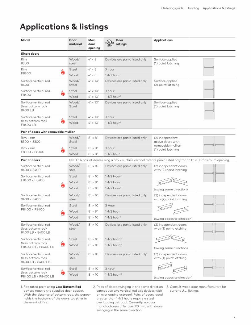
Ordering guide Handing Applications & listings
Pair of doors with removable mullion
Rim × rim 8300 × 8300
Wood/Steel
8' × 8' Devices are panic listed only (2) independent active doors with removable mullion (1) point latchingRim × rim
F8300 × F8300Steel 8' × 8' 3 hour
Wood 8' × 8' 1-1/2 hour
Model Door material
Max.door opening
Door ratings
Applications
Single doors
Rim 8300
Wood/steel
4' × 8' Devices are panic listed only Surface applied (1) point latching
Rim F8300
Steel 4' × 8' 3 hour
Wood 4' × 8' 1-1/2 hour
Surface vertical rod 8400
Wood/Steel
4' × 10' Devices are panic listed only Surface applied (2) point latching
Surface vertical rod F8400
Steel 4' × 10' 3 hour
Wood 4' × 10' 1-1/2 hour3
Surface vertical rod (less bottom rod) 8400 LB
Wood/Steel
4' × 10' Devices are panic listed only Surface applied (1) point latching
Surface vertical rod (less bottom rod) F8400 LB
Steel 4' × 10' 3 hour
Wood 4' × 10' 1-1/2 hour3
Pair of doors NOTE: A pair of doors using a rim × surface vertical rod are panic listed only for an 8' × 8' maximum opening.
Surface vertical rod 8400 × 8400
Wood/steel
8' × 10' Devices are panic listed only (2) independent doors with (2) point latching
(swing same direction)
Surface vertical rod F8400 × F8400
Steel 8' × 10' 1-1/2 Hour2
Wood 8' × 8' 1-1/2 Hour
Wood 8' × 10' 1-1/2 Hour3
Surface vertical rod 8400 × 8400
Wood/steel
8' × 10' Devices are panic listed only (2) independent doors with (2) point latching
(swing opposite direction)
Surface vertical rod F8400 × F8400
Steel 8' × 10' 3 Hour
Wood 8' × 8' 1-1/2 hour
Wood 8' × 10' 1-1/2 hour3
Surface vertical rod (less bottom rod) 8400 LB × 8400 LB
Wood/steel
8' × 10' Devices are panic listed only (2) independent doors with (1) point latching
(swing same direction)
Surface vertical rod (less bottom rod) F8400 LB × F8400 LB
Steel 8' × 10' 1-1/2 hour1,2
Wood 8' × 10' 1-1/2 hour1,3
Surface vertical rod (less bottom rod) 8400 LB × 8400 LB
Wood/steel
8' × 10' Devices are panic listed only (2) independent doors with (1) point latching
(swing opposite direction)
Surface vertical rod (less bottom rod) F8400 LB × F8400 LB
Steel 8' × 10' 3 hour1
Wood 8' × 10' 1-1/2 hour1,3
1. Fire rated pairs using Less Bottom Rod devices require the supplied door popper. With the absence of bottom rods, the popper holds the bottoms of the doors together in the event of fire.
2. Pairs of doors swinging in the same direction cannot use two vertical rod exit devices with an overlapping astragal. Pairs of doors rated greater than 1-1/2 hours require a steel overlapping astragal. Currently, no door manufacturers offer over 90 min. with doors swinging in the same direction.
3. Consult wood door manufacturers for current U.L. listings.

dormakaba
8
8000 Grade 1 exit device
3(76)1-1/2
(38)
4-7/8(122)
2-1/2(64)
1-1/4(32)
Model Function Operation Trim
8300 F8300
01 Exit Only (no trim)
8300 F8300
DT Dummy Trim 8ODT NPSDT 8HDT
8300 02 Entrance by trim when actuating bar is locked down.
8P02 8PDT PRS02 PRT02
8x02R
8ODTP
8300 F8300
03 Entrance by trim when latch bolt is retracted by key. Key removable only when locked.
8P02 8O03 NPS03 8Hx038Hx03J
8K03 8K03J
8x038x03J
8O03P 8P03 PRS03 PTS03
8300 F8300
05 Entrance by thumbpiece. Key locks or unlocks thumbpiece.
HRS05 HTS05
8300 F8300
06 Entrance by thumbpiece only when released by key. Key removable only when locked.
HRS06 HTS06
8300 F8300
08 Entrance by lever or knob. Key locks or unlocks lever or knob.
8Hx088Hx08J
8K08 8K08J
8x08 8x08J
8300F8300
09 Entrance by lever or knob when unlocked by key. Key removable only when locked.
8Hx098Hx09J
8300 22 Entrance by thumbpiece (no cylinder). Trim always active.
HRS22 HTS22
8300 F8300
23 Entrance by lever or knob (no cylinder). Lever or knob always active.
8Hx23 8K23 8x23
8300 exit device functions
Note: Where x appears above, x = lever style. See page 13 for details.
dormakaba

1-1/2(38)
5/8(16)
Minimum stile
Vertical reference
Stop29/32(23)
1-57/64(48)
1/2(13)
1-25/32(45)
29/64(12)
2-3/8(60)
5/8(16)
1-13/16(46)
1-1/8(29)
3/4(19)
5/8(16)
Minimum stile
Vertical reference
Stop
No. 430 (optional)Box strike with 8300
1-5/8(41)
Vertical reference
No. 486 (optional)Roller strike
No. 320 (optional)Overlap strike
1-1/16(27)
1-1/2(38)
15°
3/8(10)
2-1/8(54)
2(51)
* Minimum stile dimensions accommodate standard device touchbar widths shown. For smaller stiles, consult factory for optional touchbar lengths.
Not fire rated
3/4(19)
1-5/8(41)
4-1/2(114)
3-3/4(95)
Minimum stile
Vertical reference
Stop 5/8(16)
2-1/16(52)
No. 463 (standard)Standard strike with 8300 and F8300
Trim *Minimum stile
No trim, 8P02 4 (102)
8PDT, 8P03 4 (102)
8ODT, 8ODTP, 8O03, 8O03P 4-1/2 (114)
8x, 8Hx 4-7/16 (113)
Trim *Minimum stile
No trim, 8P02 3-13/16 (97)
8PDT, 8P03 4-1/8 (105)
8ODT, 8ODTP, 8O03, 8O03P 4-7/16 (113)
8x, 8Hx 4-1/4 (108)
Trim *Minimum stile
No Trim, 8P02 4-1/16 (103)
8PDT, 8P03 4-1/16 (103)
8ODT, 8ODTP, 8O03, 8O03P 4-1/16 (103)
8x, 8Hx 4 (102)
Trim *Minimum stile Vertical reference
No Trim, 8P02 4 (102) 2-1/16 (52)
8PDT, 8P03 4 (102) 2-1/16 (52)
8ODT, 8ODTP 8O03, 8O03P
4-1/2 (114) 2-1/16 (52)
8x, 8Hx 4-7/16 (113) 2-1/16 (52)
8300 strike
8300 strikes & minimum stile
Note: Where x appears above, x = lever style. See page 13 for details.
9
8300 exit device functions 8300 strikes & minimum stile

dormakaba 8000 Grade 1 exit device
10
8400 exit device functions
Note: Where x appears above, x = lever style. See page 13 for details.
dormakaba
Model Function Operation Trim
8400 F8400
01 Exit only (no trim)
8400 F8400
DT Dummy trim 8ODT NPSDT 8HDT
8400 02 Entrance by trim when actuating bar is locked down.
8P02 8PDT PRS02 PRT02
8x02R
8ODTP
8400 F8400
03 Entrance by trim when latch bolt is retracted by key. Key removable only when locked.
8P02 8O03 NPS03 8Hx038Hx03J
8K03 8K03J
8x03 8x03J
8O03P 8P03 PRS03 PTS03
8400 F8400
05 Entrance by thumbpiece. Key locks or unlocks thumbpiece.
HRS05 HTS05
8400 F8400
06 Entrance by thumbpiece only when released by key. Key removable only when locked.
HRS06 HTS06
8400 F8400
08 Entrance by lever or knob. Key locks or unlocks lever or knob.
8Hx088Hx08J
8K08 8K08J
8x08 8x08J
8400F8400
09 Entrance by lever or knob when unlocked by key. Key removable only when locked.
8Hx098Hx09J
8400 22 Entrance by thumbpiece (no cylinder). Trim always active.
HRS22 HTS22
8400 F8400
23 Entrance by lever or knob (no cylinder). Lever or knob always active.
8Hx23 8K23 8x23
3(76)1-1/2
(38) 4-7/8(122)
4-3/8(111)
1-3/8(35)
1-5/8(41)
1-5/8(41)
1-3/8(35)
4-3/8(111)
2-1/2(64)
1/2(13)
1-1/4(32)
11
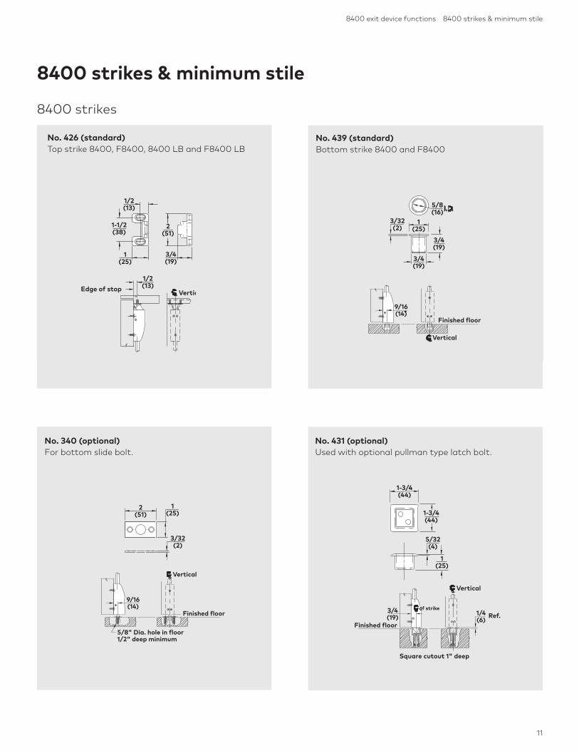
8400 exit device functions 8400 strikes & minimum stile
1/2(13)
Vertical Edge of stop
1-1/2(38)
1/2(13)
3/4(19)
1(25)
2(51)
No. 426 (standard) Top strike 8400, F8400, 8400 LB and F8400 LB
9/16(14)
Finished floor
Vertical
5/8(16)
3/32(2)
3/4(19)
3/4(19)
1(25)
No. 439 (standard)Bottom strike 8400 and F8400
8400 strikes
8400 strikes & minimum stile
Finished floor
Vertical
9/16(14)
5/8" Dia. hole in floor1/2" deep minimum
2(51)
1(25)
3/32(2)
Finished floor
Vertical
Square cutout 1" deep
Ref. of strike3/4
(19)1/4(6)
No. 340 (optional)For bottom slide bolt.
5/32(4)
1-3/4(44)
1(25)
1-3/4(44)
No. 431 (optional)Used with optional pullman type latch bolt.

Note: Where x appears above, x = lever style. See page 13 for details.
dormakaba
12
8000 Grade 1 exit device
*Minimum stile dimensions accommodate standard device touchbar widths shown. For smaller stiles, consult factory for optional touchbar lengths.
Finished floor
Vertical
5/8(16)
1-1/8(29)
5/8(16)
1/2(13)
1-13/16(46)
2-3/8(60)
Vertical
1-1/2(38) 2
(51)
2-1/4(57)
No. 416V (optional)Used with optional pullman type latch bolt.
No. 426A (optional)For flush door and frame conditions.
8400 strikes & minimum stile
Minimum stileVertical referenceEdge of door 1-7/8
(48)
Minimumstile
Vertical referenceEdge of door 1-5/8
(41)
Vertical Rod × RimVertical Rod × Vertical Rod
Minimum stile & vertical reference
Trim *Minimum stile
No trim, 8P02 3-3/16 (97)
8PDT, 8P03 3-3/16 (97)
8ODT, 8O03, 8O03P 4-5/16 (110)
8x, 8Hx 4-1/4 (108)
Not fire rated
Trim *Minimum stile
No trim, 8P02 4-1/16 (103)
8PDT, 8P03 4-1/16 (103)
8ODT, 8O03, 8O03P 4-1/16 (103)
8x, 8Hx 4 (102)

13
8400 strikes & minimum stile Trim ordering guide
X X XX X XXX XXX XX XX XX
Special finishes and coatingsCustom, designer,clear powder coat
Trimdesignation
Specialfinish
coating
Cylindersand
keying
Plate style
Knob, pull, or lever style
Function
Lever operation
Finish
Cylinder type
Keyway
Keying
Patented key controlD100 is the keyway for DORMA’s patented SKC
serialized key control system. SKC is internet based andprovides added layers of security. For more information,
contact your local sales representative orTechnical Service at 800-523-8483.
C G KR
Ordering guideHow to order 8000 Series trim
Lever & knob styles

dormakaba
14
8000 Grade 1 exit device
Trim descriptions Flat plate dummy trim Flat plate with cylinder hole Offset pull
Trim designation 80DT 8003 8PDT
Handing — — —
Function 02 03 02
dormakaba cylinder(default)
— 80R40SC – rim —
dormakaba cylinder(optional SFIC)
— 87R40BA – 7-pin —
3-1/2(89)
3/32(2)
4-1/2(114)
3-3/8(86)
1(25)
3/32(2)
5/8(16)
4-1/2(114)
3-1/2(89)
3/32(2)
4-1/2(114)
Trim descriptions Offset pull with cylinder hole Tubular pull Flat plate with tubular pull
Trim designation 8P03 8P02 80DTP
Handing — — Specify hand
Function 03 02 or 03 02
dormakaba cylinder(default)
80R40SC – rim — —
dormakaba cylinder(optional SFIC)
87R40BA – 7-pin — —
3/32(2)
3-3/8(86)5/8(16) 1
(25)
4-1/2(114)
2-1/8(54)
6-3/4(171)
3/4(19)
3/32(2)
2-1/8(54)
3-1/2(89)
4-1/2(114)
10-1/2(267)
Wide plate/pull trim

15
Wide plate/pull trim
Wide plate/pull trim
Trim descriptions Flat plate with tubular pull and cylinder hole
Wide flat plate dummy trim
Wide flat plate with cylinder hole
Trim designation 8003P NPSDT NPS03
Handing Specify hand — —
Function 03 DT 03
dormakaba cylinder(default)
80R40SC – rim — 80R40SC – rim
dormakaba cylinder(optional SFIC)
87R40BA – 7-pin — 87R40BA – 7-pin
10-1/2(267)
3/32(2)
4-1/2(114)
3-1/2(89)
2-1/8(54)
3(76)
16(406)
1/8(3)
3(76)
16(406)
1/8(3)
Trim descriptions Wide flat plate tubular pull
Wide flat plate rectangular pull
Wide flat plate rubular pull with cylinder hole
Trim designation PTS02 PRS02 PTS03
Handing — — —
Function 02 02 03
dormakaba cylinder(default)
— — 80R40SC – rim
dormakaba cylinder(optional SFIC)
— — 87R40BA – 7-pin
16(406)
3(76)
2-1/2(64)
16(406)
3(76)
1-7/8(48)
16(406)
3(76)
2-1/2(64)

dormakaba
16
8000 Grade 1 exit device
Trim descriptions Wide flat plate tubular pull with thumbpiece and cylinder hole
Wide flat plate rectangular pull with thumbpiece and cylinder hole
Raised escutcheon plate dummy trim
Trim designation HTS05, HTS06 HRS05, HRS06 8HDT
Handing — — —
Function 05 or 06 05 or 06 —
dormakaba cylinder(default)
90X10SC118 – mortise 90X10SC118 – mortise —
dormakaba cylinder(optional SFIC)
97A10BA138 – 7-pin 97A10BA138 – 7-pin —
3(76)
16(406)
2-1/2(64)
3(76)
16(406)
1-7/8(48)
Trim descriptions Wide flat plate rectangular pull with cylinder hole
Wide flat plate tubular pull with thumbpiece
Wide flat plate rectangular pull with thumbpiece
Trim designation PRS03 HTS22 HRS22
Handing — — —
Function 03 22 22
dormakaba cylinder(default)
80R40SC – rim — —
dormakaba cylinder(optional SFIC)
87R40BA – 7-pin — —
16(406)
3(76)
1-7/8(48)
3(76)
16(406)
1-7/8(48)
3(76)
16(406)
2-1/2(64)
6-3/8 (162)
2-3/4 (70) 15/16
(24)
Pull trim

17
Pull trim Escutcheon trim
Trim descriptions Raised escutcheon plate lever with rim cylinder(R trim shown)
Raised escutcheon plate lever with mortise cylinder(R trim shown)
Raised escutchen plate lever (R trim shown)
Trim designation 8Hx03 8Hx08, 8Hx09 8Hx23
Handing — — —
Function 03 08 or 09 23
dormakaba cylinder(default)
80R40SC – rim 90X10SC118 – mortise —
dormakaba cylinder(optional SFIC)
87R40BA – 7-pin 97A10BA138 – 7-pin —
Trim descriptions Raised escutcheon plate knob with rim cylinder
Raised escutcheon plate knob with mortise cylinder
Raised escutcheon plate knob
Trim designation 8HK03 8HK08, 8HK09 8HK23
Handing — — —
Function 03 08 or 09 23
dormakaba cylinder(default)
80R40SC – rim 90X10SC118 – mortise —
dormakaba cylinder(optional SFIC)
87R40BA – 7-pin 97A10BA138 – 7-pin —
2-3/4(70)
6-3/8 (162)
3-1/2 (89)
2-3/4 (70)
6-3/8 (162)
3-1/2 (89)
2-3/4 (70)
6-3/8 (162)
3-1/2 (89)
2-3/4(70)
6-3/8 (162)
3-7/16 (87)
2-3/4 (70)
6-3/8 (162)
3-7/16 (87)
2-3/4 (70)
6-3/8 (162)
3-7/16 (87)
Escutcheon trim

18
8000 Grade 1 exit device
Trim descriptions Key-in rectangular lever Key-in rectangular lever interchangeable core
Rectangular lever
Trim designation 8R03, 8R08 8R03J, 8R08J 8R02R, 8R23
Handing — — —
Function 03 or 08 03 or 08 02 or 23
dormakaba cylinder(default)
Includes key-in-lever cylinder 7013SC KD
Accepts SFIC —
dormakaba cylinder(optional SFIC)
— 77BAxxx – 7-pin —
Trim descriptions Key-in knob Key-in knob interchangeable core
Knob
Trim designation 8K03, 8K08 8K03J, 8K08J 8K23
Handing — — —
Function 03 or 08 03 or 08 23
dormakaba cylinder(default)
Includes key-in-knob cylinder 7013SC KD
Accepts SFIC —
dormakaba cylinder(optional SFIC)
— 77BAxxx – 7-pin —
dormakaba
3-3/8(86)
2-9/16(65)
4-7/8(124)
3-3/8(86)
2-9/16(65)
3-3/8(86)
2-9/16(65)
2-9/16(65)
3-3/8(86)
4-7/8(124)
3-3/8(86)
2-9/16(65)
4-7/8(124)
3-3/8(86)
2-9/16(65)
Sectional trim

19
Trim descriptions Key-in straight lever Key-in straight lever interchangeable core
Straight lever
Trim designation 8G03, 8G08 8G03J, 8G08J 8G02R, 8G23
Handing — — —
Function 03 or 08 03 or 08 02 or 23
dormakaba cylinder(default)
Includes key-in-lever cylinder 7013SC KD
Accepts SFIC —
dormakaba cylinder(optional SFIC)
— — —
Trim descriptions Key-in curved lever Key-in curved lever interchangeable core
Curved lever
Trim designation 8C03, 8C08 8C03J, 8C08J 8C02R, 8C23
Handing — — —
Function 03 or 08 03 or 08 02 or 23
dormakaba cylinder(default)
Includes key-in-lever cylinder 7013SC KD
Accepts SFIC —
dormakaba cylinder(optional SFIC)
— 77BAxxx – 7-pin —
Sectional trim
3-3/8 (86)
2-9/16 (65)
4-7/8(124)
3-3/8(86)
2-9/16(65)
4-7/8(124)
3-3/8(86)
4-7/8(124)
2-9/16(65)
3-3/8(86)
2-9/16(65)
4-7/8(124)
3-3/8(86)
4-7/8(124)
2-9/16(65)
4-7/8(124)
2-9/16(65)
3-3/8(86)
Sectional trim

20
8000 Grade 1 exit devicedormakaba
Conventional SFIC
Conventional
SFIC
Conventional
SFIC
Rim cylinders Mortise cylinders Key-in-lever cylinders
Application ANSI function Cylinder type Conventional (default)
SFIC 7-Pin
Cylinders for 8300/F8300 rim and 8400/F8400 surface vertical rod devices
Sectional trim (key-in-lever) 03, 08 Key-in-lever 7013SC 77BA
Wide plate trim 03 Rim 80R40SC 87R40BA
Wide plate trim 05, 06 Mortise 90X10SC118 97C10BA138
Pulls 03 Rim 80R40SC 87R40BA
Cylinders for device options
CD, BPA, BPAR Mortise 90X10SC118 97D10BA138
Cylinders for mullions
1340KR key removable mullion Mortise 90X01SC118 97D01BA138
1340SK mullion storage kit Mortise 90X01SC118 97D01BA138
8300/F8300 3 pack
8300/F8300 w/ trim 1 pack
8400/F8400 5 packs
8400/F8400 w/ trim 4 packs
GK8000 Glass lite shim kit Kit contains two 1/8" thick shims. Permits shimming of the exit device maximum 1/4" off door face without affecting U.L. listing. De-signed to accommodate glass lite installed in door. Furnished bright zinc plated. Optional finishes available, consult factory.
Sex nuts The information below serves as a simple reference when specifying 8000 Series exit devices and trim (two per pack).
Accessories
Cylinder specifications
Keyways
AA Arrow A
CA Corbin 60
CB Corbin 67
CC Corbin 77
CD Corbin 59A1
CE Cor Russ L4
D100 DORMA SKC
GA Sargent LA
RA Russwin 981
RB Russwin D1
SC Schlage C
SE Schlage E
SF Schlage F
YA Yale 8
YG Yale GA

21
Cylinder specifications Accessories Optional electrical functions
8300/F8300 3 pack
8300/F8300 w/ trim 1 pack
8400/F8400 5 packs
8400/F8400 w/ trim 4 packs
Electric latch bolt retraction Specify prefix ES. A solenoid concealed in the touchbar assembly provides instantaneous retraction of the latch bolt to allow access from the secure side of the door. Remote control can be accomplished with switching devices such as key switches and card readers that provide a normally open electrical contact. The solenoid is rated for continuous duty, 24 VDC, 5 AMP inrush for 350 milliseconds, .21 AMP holding current. Requires ES100 power supply and ES105 power transfer.
Monitor switch Specify prefix MS. A reed switch in the touchbar assembly which provides local and/or remote notification when the touchbar is depressed. Switch is rated for 3 AMP @ 28 VDC.
Latch monitor Specify prefix LM. A microswitch attached to the device chassis on rated and non-rated 8300, 8400 and 8400 LB. Provides local and/or remote notification of movement of the panic device rods and latch bolt without depressing the touchbar. The switch is a single pole, double throw switch, 0.5 AMP @ 28 VDC maximum.
ES100 power supply The ES100 power supply is capable of powering and controlling (2) 8000 Series exit devices with the ES electric latch bolt retraction feature.
• Input: 120 volts• Input circuit protection: 1.3 AMP fuse• Output: 24 VDC, 6 AMP surge for 0.5
seconds, .65 AMP continuous, per zone
• Output circuit protection: 3 AMP Push to Reset circuit breaker
• Enclosure: 8" high × 8" wide × 4" deep NEMA 1 Type enclosure for indoor use with hinged cover and knock-outs
ES101 delay moduleThe ES101 optional time delay module for the ES100 Power supply delays the relatching of ES series exit devices and has field-adjustable range between 1 second and 60 minutes.
This is a fail-secure option that allows time to enter a door after using a card reader or key switch, or may be required when ES Series panic devices are used in conjunction with an automatic door operator.
ES103 relay moduleThe ES103 optional relay module is a double pole, double throw relay with screw terminal connections. This coil rating is .025 AMP @ 24 VDC. The contact rating is 2.0 AMP @ 30 VDC.
Relays may be wired in parallel if additional contacts are required. This relay may be required to signal other systems such as an automatic door operator.
Battery alarm exit deviceThe 8000 Series exit devices are available with an integral battery powered alarm. The 102 decibel alarm contained in the exit device touchbar and rail assembly activates when the touchbar is depressed and sounds continuously until the device is reset or the battery is completely discharged. Alternatively, a factory-furnished option allows the alarm to sound for four (4) minutes, then automatically rearms.
Furnished with and controlled by a lock cylinder and key, the unit allows ten (10) seconds to exit through the door after arming the alarm, indicated by an intermittently flashing red LED light in the touchbar. A yellow LED in the touchbar will flash, until manually reset by key, to indicate an unauthorized exit even if the alarm has automatically reset.
The unit is furnished with a 9 V, industri-al-grade battery concealed in the end cap assembly for easy replacement. A tamperproof switch will activate the alarm if unauthorized removal of the battery is attempted. Option is available for 12 or 24 V direct power wiring.
EMERGENCY EXIT ONLYPUSH TO OPEN ALARM WILL SOUND
• Specify prefix BPA to 8000 Series model number for battery alarm device.
• Specify prefix BPAR for 4 minute auto reset battery alarm device.
• Specify prefix DWA for direct hard-wired option.
• Size A device fits 48" wide door and can be cut to fit 34" wide doors.
• Size B device fits 36" wide door and can be cut to fit 28" wide doors.
• Size C device fits 36" wide door and can be cut to fit 22" wide doors.
Optional electrical functions

22
8000 Grade 1 exit devicedormakaba
1-5/8(41)
2-5/8(67)
1-1/8(29)
Weatherstrip slots
Finished floor
Top fitting
443 Strike
Bottom fitting
Stabilizers(Installed on door)
1310 aluminum mullion
• Meets demands of heaviest use areas.
• Durable extrusion.• Supplied with wood/
machine screws and anchors.
1310–8 — 8' mullion1310–10 — 10' mullion1310–8 × 443 — 8' mullion with recessed strike1310–10 × 443 — 10' mullion with recessed strike
WS1310–8 — 8' mullion with weatherstripWS1310–10 — 10' mullion with weatherstripWS1310–8 × 443 — 8'mullion with weatherstrip and recessed strikes WS1310–10 × 443 — 10'mullion with weatherstrip and recessed strikes
FinishAluminum: 628 (satin)Bronze: 695 (dark)
1330 steel mullion
1-1/2(38)
2-1/2(64)
.120(11 gage)
Finished floor
• Ideal for high-abuse areas such as schools.
• Meets demands of heaviest use areas.
• Heavy-gauge, smooth-surface steel construction.
• Attractive tube shape with rounded corners.
• Supplied with wood/machine screws and anchors.
1330–8 — 8' mullion1330–10 — 10' mullion FinishPrime: 600
Top fitting
Stabilizers(installed on door)
Bottom fitting
Mullions

23
Mullions
F1300 steel mullion
Bottom fitting
Set screw
Top fittingSet screw
Stabilizers(installed on door)
Finished floor
2(51)
.120(11 gage)
3(76)
• For use with U.L. listed fire exit devices.
• Meets demands of heaviest use areas.
• Large top and bottom fittings for extra strength.
• Heavy-duty tube with rounded corners.
• Standard 8' length.• Supplied with wood/
machine screws and anchors.
F1300–8 — 8' fire-rated mullion1300–8 — 8' non-fire-rated mullion1300–10 — 10' non-fire-rated mullion
FinishPrime: 600
• Easily removable with key.
• Keying is standard 1-1/8" mortise cylinder with 01 (AR) cam.
• For use with U.L. listed fire exit devices.
• Meets demands of heaviest use areas.
• Large top and bottom fittings for extra strength.
• Heavy-duty tube with rounded corners.
• Standard 8' length.• Supplied with wood/
machine screws and anchors.
F1340KR–8 — 8' fire-rated key removable mullion1340KR–8 — 8' non-fire-rated key removable mullion1340KR–10 — 10' non-fire-rated key removable mullion
1340KREL–8 — 8' non-fire-rated wired key removable mullion 1340KREL–10 — 10' non- fire-rated wired key removable mullion
FinishPrime: 600 Optional SFIC97D01BA138 – 7-pin
1340SK Mullion Storage Kit• For use with 1340
mullion.• Locking cylinder can be
keyed into master key system.
• Includes conventional default mortise cylinder: 90X01SC118 626.
Optional SFIC97D01BA138 – 7-pin
Top fitting
Mortise cylinder90X01SC118 626(supplied)
Stabilizers(installed on door)
Set screw
Bottom fitting
Unlocked
Locked
Finished floor
F1340KR key removable steel mullion
2(51)
.120(11 gage)
3(76)

070
00
268
∙ 3
17C
T ∙
2M ∙
USA
DORMA USA, Inc.Dorma Drive, Drawer ACReamstown, PA 17567Tel: 800 523 8483Fax: 800 274 [email protected]
DORMA Canada1680 Courtney Park Drive, Unit 13Mississauga, Ontario L5T 1R4Tel: 800 387 4938Fax: 905 670 [email protected]
DORMA MexicoCalle Sur 110 no. 63, Col. Tolteca 01150 México, D.F. Tel: 5255 5272 6937Fax: 5255 5272 6948
www.dormakaba.us