Embed Size (px)
Citation preview
NON-METALLIC EXPANSION JOINTSAPPLICATION & DESIGN GUIDE
$8.00
2315 W. HUBBARD ST. • CHICAGO, IL 60612 • 800-533-1024 • 312-738-3588 • FAX 312-421-6327

3www.flexicraft.com
How to Order Flexicraft Non-Metallic Expansion Joints
Please Provide the Following Information (as a minimum):
1. Size of Line: Nominal Pipe Diameter 2. System Application: Flowing Media, Requirements 3. Pressure or Vacuum: Internal, External 4. Temperature: Operating, Ambient 5. Movement: Direction, Amount 6. Need for Control Units: Based on System Anchoring 7. End Fittings: ANSI, DIN, British Standard, Metric, etc.
This guide provides additional information on the details of choosing a joint for a given application. However, with the above information our engineers can choose a joint right for your needs.
Flexicraft has been supplying industry with quality piping products for over 40 years. Our reputation for superior products and technical support sets us apart from our competition.
In addition to non-metallic expansion joints, Flexicraft is a supplier of metallic expansion joints, braided hose, expansion loops, pulsation dampeners, and other specialty piping products using bellows technologies. For more information or to order,
Contact us at:
800-533-1024(312) 738-3588 • (312) 421-6327 Fax
www.flexicraft.comor contact the representative in your area - see back cover.
INDUSTRIES
www.flexicraft.com4
Non-Metallic Expansion Joints
Elastomer (rubber) and Teflon® expansion joints have been specified for many years to accom-modate movement in piping runs and insure efficient systems. Elastomer joints are widely used to provide efficient ways to relieve movement stresses, reduce noise, isolate vibration, compen-sate for misalignment. Teflon joints are used with highly corrosive media, with glass piping, or in systems where space is at a premium.
Elastomeric expansion joints are fabricated from synthetic elastomers and fabric, and are often reinforced with metal. When operating temperatures and pressures exceed 250°F and 200 psig, respectively, rubber should not usually be considered an alternative to metallic expan-sion joints. Within these limits, elastomeric joints do offer advantages compared with metal joints, including:
1. Cycle Life - Many more cycles can be provided, and vibration fatigue is not a concern. 2. Stress Corrosion - They are chemically inert to most common corrosive elements.
3. Resistance to Abrasion and Erosion - They outlast metal joints in this respect.
4. Resistance to External Damage - With elastomer joints, accidental external blows do not cause damage.
5. Space Requirements - Metal joints require a considerably greater face-to-face dimensions.
6. Acoustical Impedance - They absorb a great deal of noise and vibration.
7. Light Weight - They are easy to handle and compact.
8. Low Cost - In general, they are less expensive than metal joints.
Teflon expansion joints also have certain advantages, which include: 1. Chemical Resistance - Molded and machined Teflon connectors are used in corrosive applications due to the inherent resistance of the material to a vast range of chemicals.
2. Acoustical Impedance - They absorb noise and vibration.
3. Temperature Limits - Teflon can withstand temperatures as high as 450° F and as low as -10° F.
Flexicraft provides complete lines of non-metallic joints to best meet your needs. The following pages describe our products and their proper usage.
5www.flexicraft.com
Table Of Contents
Flexicraft Products Ultrasphere . . . . . . . . . . . . . . . . . . . . . . . . . . . . . . . . . . . . . . . page 6 Ultrasphere Twin . . . . . . . . . . . . . . . . . . . . . . . . . . . . . . . . . . . page 7 Flextra 150 . . . . . . . . . . . . . . . . . . . . . . . . . . . . . . . . . . . . . . . . page 8 Ultraspool . . . . . . . . . . . . . . . . . . . . . . . . . . . . . . . . . . . . . page 9-10 Ultraspool Double . . . . . . . . . . . . . . . . . . . . . . . . . . . . . . . . page 11 Ultraspool Triple . . . . . . . . . . . . . . . . . . . . . . . . . . . . . . . . . . page 12 Concentric Reducer . . . . . . . . . . . . . . . . . . . . . . . . . . . . . . page 13 Duct Expansion Joints . . . . . . . . . . . . . . . . . . . . . . . . . . . . . page 14 Flexible Rubber Pipe . . . . . . . . . . . . . . . . . . . . . . . . . . . . . . page 15 Flexible Couplings . . . . . . . . . . . . . . . . . . . . . . . . . . . . . . . . page 15 Teflex Expansion Joints . . . . . . . . . . . . . . . . . . . . . . . . . . . . page 16
Performance Characteristics Temperature Class . . . . . . . . . . . . . . . . . . . . . . . . . . . . . . . . page 17 Sound Limiting . . . . . . . . . . . . . . . . . . . . . . . . . . . . . . . . . . . page 17 Physical and Chemical Properties of Materials . . . . . . . . page 17
Construction Details Assembly Terminology . . . . . . . . . . . . . . . . . . . . . . . . . . . . page 18 Control Units . . . . . . . . . . . . . . . . . . . . . . . . . . . . . . . . . . . . . page 19 Designs for Turbulence and Abrasion . . . . . . . . . . . . . . . . page 19
Installation Anchoring . . . . . . . . . . . . . . . . . . . . . . . . . . . . . . . . . . . . . . . page 20 Control Units . . . . . . . . . . . . . . . . . . . . . . . . . . . . . . . . . . page 20-21
Terms and Conditions . . . . . . . . . . . . . . . . . . . . . . . . . . . . . . . . . . page 22
www.flexicraft.com6
Flexicraft Quality Products
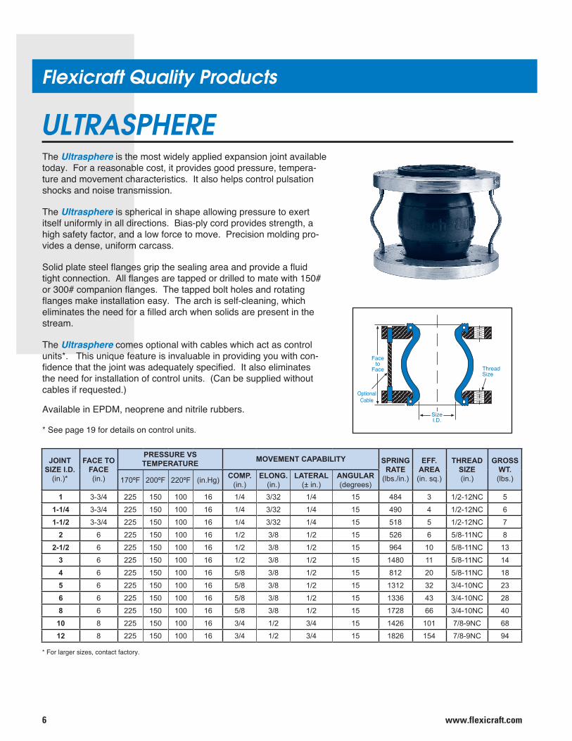
ULTRASPHEREThe Ultrasphere is the most widely applied expansion joint available today. For a reasonable cost, it provides good pressure, tempera-ture and movement characteristics. It also helps control pulsation shocks and noise transmission.
The Ultrasphere is spherical in shape allowing pressure to exert itself uniformly in all directions. Bias-ply cord provides strength, a high safety factor, and a low force to move. Precision molding pro-vides a dense, uniform carcass.
Solid plate steel flanges grip the sealing area and provide a fluid tight connection. All flanges are tapped or drilled to mate with 150# or 300# companion flanges. The tapped bolt holes and rotating flanges make installation easy. The arch is self-cleaning, which eliminates the need for a filled arch when solids are present in the stream.
The Ultrasphere comes optional with cables which act as control units*. This unique feature is invaluable in providing you with con-fidence that the joint was adequately specified. It also eliminates the need for installation of control units. (Can be supplied without cables if requested.)
Available in EPDM, neoprene and nitrile rubbers.
* See page 19 for details on control units.
Faceto
Face
OptionalCable
SizeI.D.
ThreadSize
* For larger sizes, contact factory.
JOINTSIZE I.D.
(in.)*
FACE TO FACE(in.)
PRESSURE VSTEMPERATURE MOVEMENT CAPABILITY SPRING
RATE(lbs./in.)
EFF.AREA(in. sq.)
THREADSIZE(in.)
GROSSWT.(lbs.)170ºF 200ºF 220ºF (in.Hg) COMP.
(in.)ELONG.
(in.)LATERAL
(± in.)ANGULAR(degrees)
1 3-3/4 225 150 100 16 1/4 3/32 1/4 15 484 3 1/2-12NC 5
1-1/4 3-3/4 225 150 100 16 1/4 3/32 1/4 15 490 4 1/2-12NC 6
1-1/2 3-3/4 225 150 100 16 1/4 3/32 1/4 15 518 5 1/2-12NC 7
2 6 225 150 100 16 1/2 3/8 1/2 15 526 6 5/8-11NC 8
2-1/2 6 225 150 100 16 1/2 3/8 1/2 15 964 10 5/8-11NC 13
3 6 225 150 100 16 1/2 3/8 1/2 15 1480 11 5/8-11NC 14
4 6 225 150 100 16 5/8 3/8 1/2 15 812 20 5/8-11NC 18
5 6 225 150 100 16 5/8 3/8 1/2 15 1312 32 3/4-10NC 23
6 6 225 150 100 16 5/8 3/8 1/2 15 1336 43 3/4-10NC 28
8 6 225 150 100 16 5/8 3/8 1/2 15 1728 66 3/4-10NC 40
10 8 225 150 100 16 3/4 1/2 3/4 15 1426 101 7/8-9NC 68
12 8 225 150 100 16 3/4 1/2 3/4 15 1826 154 7/8-9NC 94
7www.flexicraft.com
Flexicraft Quality Products
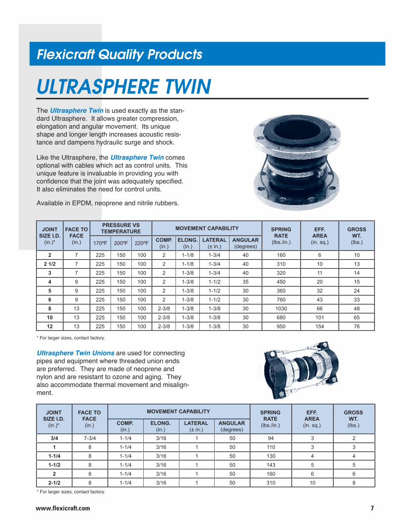
ULTRASPHERE TWIN
Ultrasphere Twin Unions are used for connecting pipes and equipment where threaded union ends are preferred. They are made of neoprene and nylon and are resistant to ozone and aging. They also accommodate thermal movement and misalign-ment.
The Ultrasphere Twin is used exactly as the stan-dard Ultrasphere. It allows greater compression, elongation and angular movement. Its unique shape and longer length increases acoustic resis-tance and dampens hydraulic surge and shock.
Like the Ultrasphere, the Ultrasphere Twin comes optional with cables which act as control units. This unique feature is invaluable in providing you with confidence that the joint was adequately specified. It also eliminates the need for control units.
Available in EPDM, neoprene and nitrile rubbers.
* For larger sizes, contact factory.
* For larger sizes, contact factory.
JOINTSIZE I.D.
(in.)*
FACE TO FACE(in.)
PRESSURE VSTEMPERATURE MOVEMENT CAPABILITY SPRING
RATE(lbs./in.)
EFF.AREA(in. sq.)
GROSSWT.(lbs.)170ºF 200ºF 220ºF COMP.
(in.)ELONG.
(in.)LATERAL
(± in.)ANGULAR(degrees)
2 7 225 150 100 2 1-1/8 1-3/4 40 160 6 10
2 1/2 7 225 150 100 2 1-1/8 1-3/4 40 310 10 13
3 7 225 150 100 2 1-3/8 1-3/4 40 320 11 14
4 9 225 150 100 2 1-3/8 1-1/2 35 450 20 15
5 9 225 150 100 2 1-3/8 1-1/2 30 360 32 24
6 9 225 150 100 2 1-3/8 1-1/2 30 760 43 33
8 13 225 150 100 2-3/8 1-3/8 1-3/8 30 1030 66 48
10 13 225 150 100 2-3/8 1-3/8 1-3/8 30 680 101 65
12 13 225 150 100 2-3/8 1-3/8 1-3/8 30 950 154 76
JOINTSIZE I.D.
(in.)*
FACE TO FACE(in.)
MOVEMENT CAPABILITY SPRINGRATE
(lbs./in.)
EFF.AREA(in. sq.)
GROSSWT.(lbs.)COMP.
(in.)ELONG.
(in.)LATERAL
(± in.)ANGULAR(degrees)
3/4 7-3/4 1-1/4 3/16 1 50 94 3 2
1 8 1-1/4 3/16 1 50 110 3 3
1-1/4 8 1-1/4 3/16 1 50 130 4 4
1-1/2 8 1-1/4 3/16 1 50 143 5 5
2 8 1-1/4 3/16 1 50 160 6 6
2-1/2 8 1-1/4 3/16 1 50 310 10 8
www.flexicraft.com8
Flexicraft Quality Products
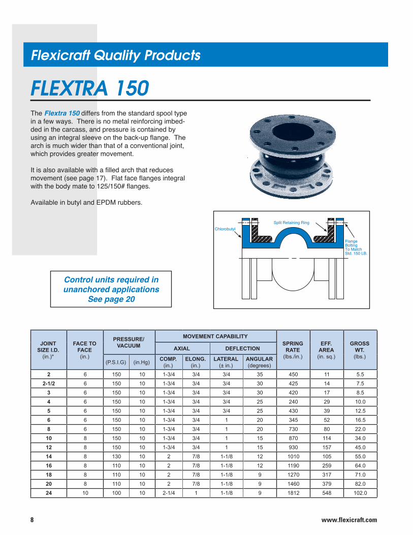
FLEXTRA 150The Flextra 150 differs from the standard spool type in a few ways. There is no metal reinforcing imbed-ded in the carcass, and pressure is contained by using an integral sleeve on the back-up flange. The arch is much wider than that of a conventional joint, which provides greater movement.
It is also available with a filled arch that reduces movement (see page 17). Flat face flanges integral with the body mate to 125/150# flanges.
Available in butyl and EPDM rubbers.
Control units required in unanchored applications
See page 20
Chlorobutyl
FlangeBoltingTo MatchStd. 150 LB.
Split Retaining Ring
JOINTSIZE I.D.
(in.)*
FACE TO FACE(in.)
PRESSURE/VACUUM
MOVEMENT CAPABILITYSPRING
RATE(lbs./in.)
EFF.AREA(in. sq.)
GROSSWT.(lbs.)
AXIAL DEFLECTION
(P.S.I.G) (in.Hg) COMP.(in.)
ELONG.(in.)
LATERAL(± in.)
ANGULAR(degrees)
2 6 150 10 1-3/4 3/4 3/4 35 450 11 5.5
2-1/2 6 150 10 1-3/4 3/4 3/4 30 425 14 7.5
3 6 150 10 1-3/4 3/4 3/4 30 420 17 8.5
4 6 150 10 1-3/4 3/4 3/4 25 240 29 10.0
5 6 150 10 1-3/4 3/4 3/4 25 430 39 12.5
6 6 150 10 1-3/4 3/4 1 20 345 52 16.5
8 6 150 10 1-3/4 3/4 1 20 730 80 22.0
10 8 150 10 1-3/4 3/4 1 15 870 114 34.0
12 8 150 10 1-3/4 3/4 1 15 930 157 45.0
14 8 130 10 2 7/8 1-1/8 12 1010 105 55.0
16 8 110 10 2 7/8 1-1/8 12 1190 259 64.0
18 8 110 10 2 7/8 1-1/8 9 1270 317 71.0
20 8 110 10 2 7/8 1-1/8 9 1460 379 82.0
24 10 100 10 2-1/4 1 1-1/8 9 1812 548 102.0
9www.flexicraft.com
Flexicraft Quality Products
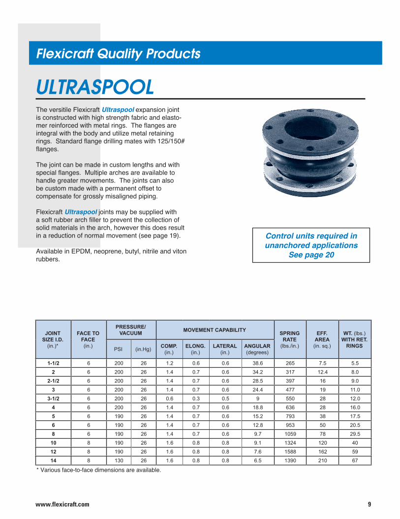
ULTRASPOOLThe versitile Flexicraft Ultraspool expansion joint is constructed with high strength fabric and elasto-mer reinforced with metal rings. The flanges are integral with the body and utilize metal retaining rings. Standard flange drilling mates with 125/150# flanges.
The joint can be made in custom lengths and with special flanges. Multiple arches are available to handle greater movements. The joints can also be custom made with a permanent offset to compensate for grossly misaligned piping.
Flexicraft Ultraspool joints may be supplied with a soft rubber arch filler to prevent the collection of solid materials in the arch, however this does result in a reduction of normal movement (see page 19).
Available in EPDM, neoprene, butyl, nitrile and viton rubbers.
Control units required in unanchored applications
See page 20
* Various face-to-face dimensions are available.
JOINTSIZE I.D.
(in.)*
FACE TO FACE(in.)
PRESSURE/VACUUM MOVEMENT CAPABILITY SPRING
RATE(lbs./in.)
EFF.AREA(in. sq.)
WT. (lbs.)WITH RET.
RINGSPSI (in.Hg) COMP.(in.)
ELONG.(in.)
LATERAL(in.)
ANGULAR(degrees)
1-1/2 6 200 26 1.2 0.6 0.6 38.6 265 7.5 5.5
2 6 200 26 1.4 0.7 0.6 34.2 317 12.4 8.0
2-1/2 6 200 26 1.4 0.7 0.6 28.5 397 16 9.0
3 6 200 26 1.4 0.7 0.6 24.4 477 19 11.0
3-1/2 6 200 26 0.6 0.3 0.5 9 550 28 12.0
4 6 200 26 1.4 0.7 0.6 18.8 636 28 16.0
5 6 190 26 1.4 0.7 0.6 15.2 793 38 17.5
6 6 190 26 1.4 0.7 0.6 12.8 953 50 20.5
8 6 190 26 1.4 0.7 0.6 9.7 1059 78 29.5
10 8 190 26 1.6 0.8 0.8 9.1 1324 120 40
12 8 190 26 1.6 0.8 0.8 7.6 1588 162 59
14 8 130 26 1.6 0.8 0.8 6.5 1390 210 67
www.flexicraft.com10
Flexicraft Quality Products
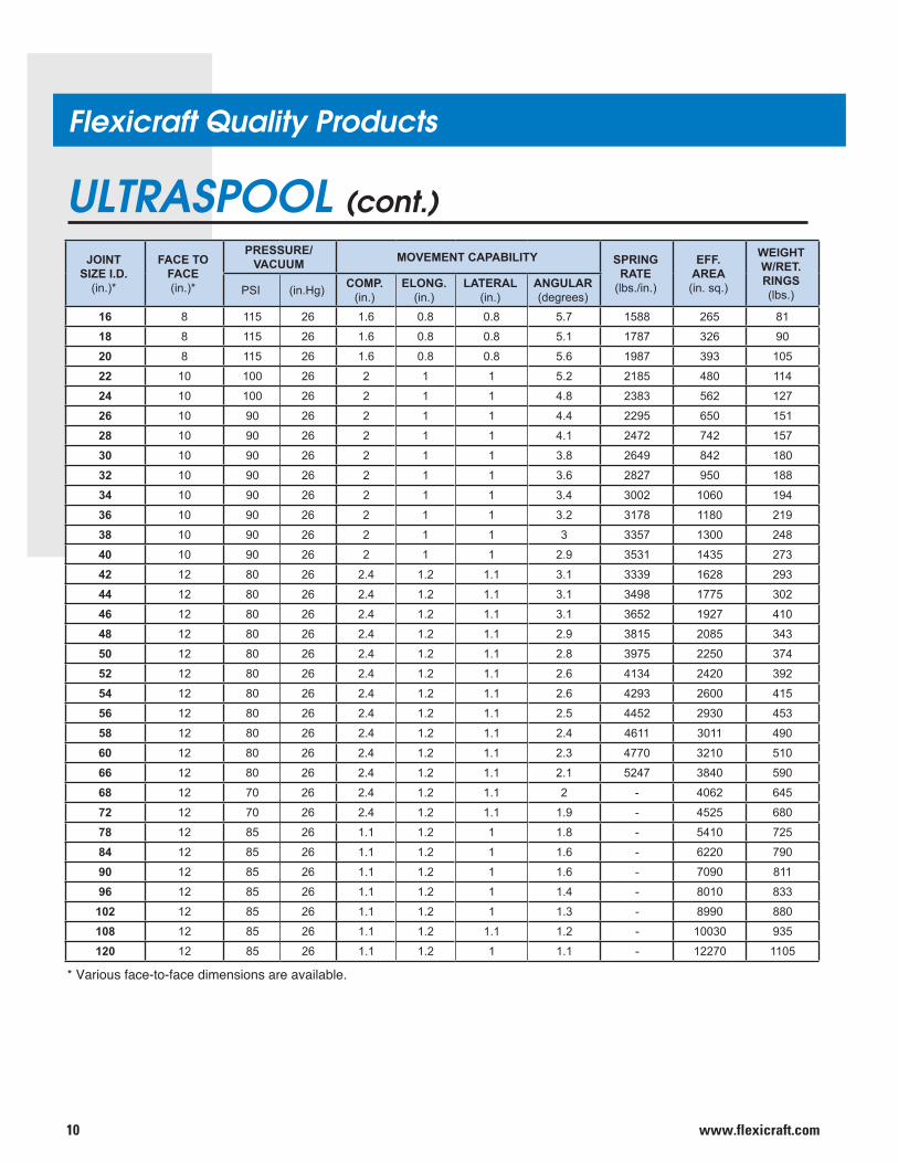
ULTRASPOOL (cont.)
* Various face-to-face dimensions are available.
JOINTSIZE I.D.
(in.)*
FACE TO FACE(in.)*
PRESSURE/VACUUM MOVEMENT CAPABILITY SPRING
RATE(lbs./in.)
EFF.AREA(in. sq.)
WEIGHTW/RET.RINGS(lbs.)PSI (in.Hg) COMP.
(in.)ELONG.
(in.)LATERAL
(in.)ANGULAR(degrees)
16 8 115 26 1.6 0.8 0.8 5.7 1588 265 81
18 8 115 26 1.6 0.8 0.8 5.1 1787 326 90
20 8 115 26 1.6 0.8 0.8 5.6 1987 393 105
22 10 100 26 2 1 1 5.2 2185 480 114
24 10 100 26 2 1 1 4.8 2383 562 127
26 10 90 26 2 1 1 4.4 2295 650 151
28 10 90 26 2 1 1 4.1 2472 742 157
30 10 90 26 2 1 1 3.8 2649 842 180
32 10 90 26 2 1 1 3.6 2827 950 188
34 10 90 26 2 1 1 3.4 3002 1060 194
36 10 90 26 2 1 1 3.2 3178 1180 219
38 10 90 26 2 1 1 3 3357 1300 248
40 10 90 26 2 1 1 2.9 3531 1435 273
42 12 80 26 2.4 1.2 1.1 3.1 3339 1628 293
44 12 80 26 2.4 1.2 1.1 3.1 3498 1775 302
46 12 80 26 2.4 1.2 1.1 3.1 3652 1927 410
48 12 80 26 2.4 1.2 1.1 2.9 3815 2085 343
50 12 80 26 2.4 1.2 1.1 2.8 3975 2250 374
52 12 80 26 2.4 1.2 1.1 2.6 4134 2420 392
54 12 80 26 2.4 1.2 1.1 2.6 4293 2600 415
56 12 80 26 2.4 1.2 1.1 2.5 4452 2930 453
58 12 80 26 2.4 1.2 1.1 2.4 4611 3011 490
60 12 80 26 2.4 1.2 1.1 2.3 4770 3210 510
66 12 80 26 2.4 1.2 1.1 2.1 5247 3840 590
68 12 70 26 2.4 1.2 1.1 2 - 4062 645
72 12 70 26 2.4 1.2 1.1 1.9 - 4525 680
78 12 85 26 1.1 1.2 1 1.8 - 5410 725
84 12 85 26 1.1 1.2 1 1.6 - 6220 790
90 12 85 26 1.1 1.2 1 1.6 - 7090 811
96 12 85 26 1.1 1.2 1 1.4 - 8010 833
102 12 85 26 1.1 1.2 1 1.3 - 8990 880
108 12 85 26 1.1 1.2 1.1 1.2 - 10030 935
120 12 85 26 1.1 1.2 1 1.1 - 12270 1105
11www.flexicraft.com
Flexicraft Quality Products
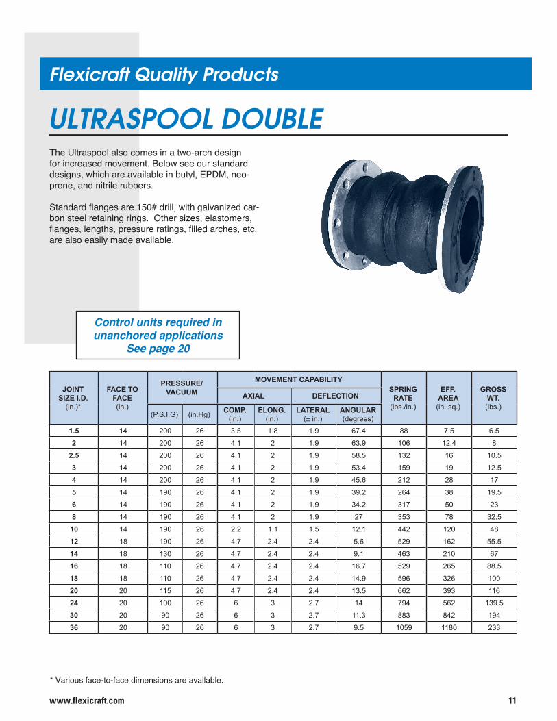
ULTRASPOOL DOUBLEThe Ultraspool also comes in a two-arch design for increased movement. Below see our standard designs, which are available in butyl, EPDM, neo-prene, and nitrile rubbers.
Standard flanges are 150# drill, with galvanized car-bon steel retaining rings. Other sizes, elastomers, flanges, lengths, pressure ratings, filled arches, etc. are also easily made available.
JOINTSIZE I.D.
(in.)*
FACE TO FACE(in.)
PRESSURE/VACUUM
MOVEMENT CAPABILITYSPRING
RATE(lbs./in.)
EFF.AREA(in. sq.)
GROSSWT.(lbs.)
AXIAL DEFLECTION
(P.S.I.G) (in.Hg) COMP.(in.)
ELONG.(in.)
LATERAL(± in.)
ANGULAR(degrees)
1.5 14 200 26 3.5 1.8 1.9 67.4 88 7.5 6.5
2 14 200 26 4.1 2 1.9 63.9 106 12.4 8
2.5 14 200 26 4.1 2 1.9 58.5 132 16 10.5
3 14 200 26 4.1 2 1.9 53.4 159 19 12.5
4 14 200 26 4.1 2 1.9 45.6 212 28 17
5 14 190 26 4.1 2 1.9 39.2 264 38 19.5
6 14 190 26 4.1 2 1.9 34.2 317 50 23
8 14 190 26 4.1 2 1.9 27 353 78 32.5
10 14 190 26 2.2 1.1 1.5 12.1 442 120 48
12 18 190 26 4.7 2.4 2.4 5.6 529 162 55.5
14 18 130 26 4.7 2.4 2.4 9.1 463 210 67
16 18 110 26 4.7 2.4 2.4 16.7 529 265 88.5
18 18 110 26 4.7 2.4 2.4 14.9 596 326 100
20 20 115 26 4.7 2.4 2.4 13.5 662 393 116
24 20 100 26 6 3 2.7 14 794 562 139.5
30 20 90 26 6 3 2.7 11.3 883 842 194
36 20 90 26 6 3 2.7 9.5 1059 1180 233
Control units required in unanchored applications
See page 20
* Various face-to-face dimensions are available.
www.flexicraft.com12
Flexicraft Quality Products
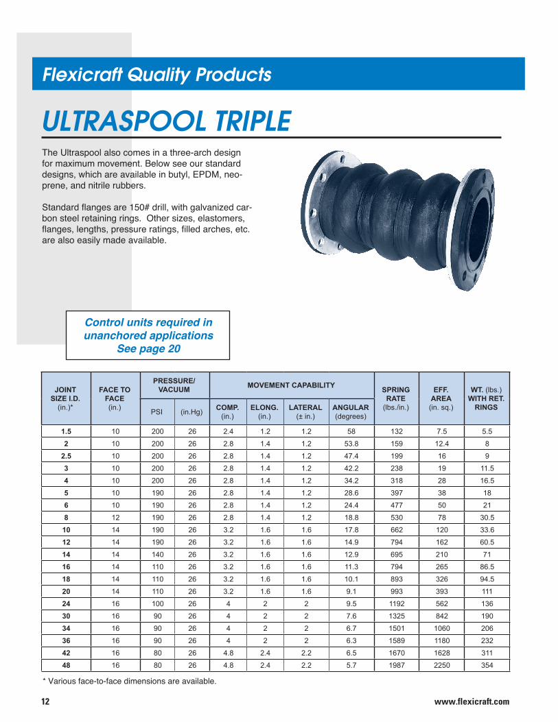
ULTRASPOOL TRIPLEThe Ultraspool also comes in a three-arch design for maximum movement. Below see our standard designs, which are available in butyl, EPDM, neo-prene, and nitrile rubbers.
Standard flanges are 150# drill, with galvanized car-bon steel retaining rings. Other sizes, elastomers, flanges, lengths, pressure ratings, filled arches, etc. are also easily made available.
* Various face-to-face dimensions are available.
JOINTSIZE I.D.
(in.)*
FACE TO FACE(in.)
PRESSURE/VACUUM MOVEMENT CAPABILITY SPRING
RATE(lbs./in.)
EFF.AREA(in. sq.)
WT. (lbs.)WITH RET.
RINGSPSI (in.Hg) COMP.(in.)
ELONG.(in.)
LATERAL(± in.)
ANGULAR(degrees)
1.5 10 200 26 2.4 1.2 1.2 58 132 7.5 5.5
2 10 200 26 2.8 1.4 1.2 53.8 159 12.4 8
2.5 10 200 26 2.8 1.4 1.2 47.4 199 16 9
3 10 200 26 2.8 1.4 1.2 42.2 238 19 11.5
4 10 200 26 2.8 1.4 1.2 34.2 318 28 16.5
5 10 190 26 2.8 1.4 1.2 28.6 397 38 18
6 10 190 26 2.8 1.4 1.2 24.4 477 50 21
8 12 190 26 2.8 1.4 1.2 18.8 530 78 30.5
10 14 190 26 3.2 1.6 1.6 17.8 662 120 33.6
12 14 190 26 3.2 1.6 1.6 14.9 794 162 60.5
14 14 140 26 3.2 1.6 1.6 12.9 695 210 71
16 14 110 26 3.2 1.6 1.6 11.3 794 265 86.5
18 14 110 26 3.2 1.6 1.6 10.1 893 326 94.5
20 14 110 26 3.2 1.6 1.6 9.1 993 393 111
24 16 100 26 4 2 2 9.5 1192 562 136
30 16 90 26 4 2 2 7.6 1325 842 190
34 16 90 26 4 2 2 6.7 1501 1060 206
36 16 90 26 4 2 2 6.3 1589 1180 232
42 16 80 26 4.8 2.4 2.2 6.5 1670 1628 311
48 16 80 26 4.8 2.4 2.2 5.7 1987 2250 354
Control units required in unanchored applications
See page 20
13www.flexicraft.com
Flexicraft Quality Products
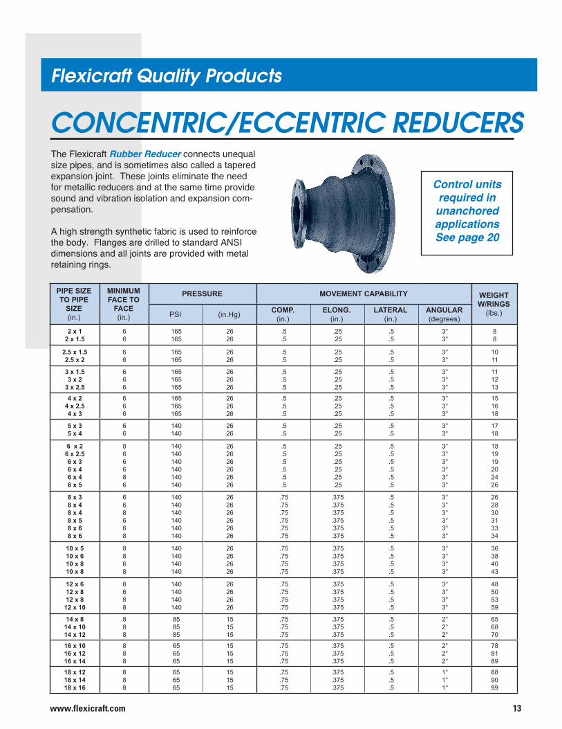
CONCENTRIC/ECCENTRIC REDUCERSThe Flexicraft Rubber Reducer connects unequal size pipes, and is sometimes also called a tapered expansion joint. These joints eliminate the need for metallic reducers and at the same time provide sound and vibration isolation and expansion com-pensation.
A high strength synthetic fabric is used to reinforce the body. Flanges are drilled to standard ANSI dimensions and all joints are provided with metal retaining rings.
Control units required in unanchored applications See page 20
PIPE SIZETO PIPE
SIZE(in.)
MINIMUMFACE TO
FACE(in.)
PRESSURE MOVEMENT CAPABILITY WEIGHTW/RINGS
(lbs.)PSI (in.Hg) COMP.(in.)
ELONG.(in.)
LATERAL(in.)
ANGULAR(degrees)
2 x 12 x 1.5
66
165165
2626
.5
.5.25.25
.5
.53°3°
88
2.5 x 1.52.5 x 2
66
165165
2626
.5
.5.25.25
.5
.53°3°
1011
3 x 1.53 x 2
3 x 2.5
666
165165165
262626
.5
.5
.5
.25
.25
.25
.5
.5
.5
3°3°3°
111213
4 x 24 x 2.54 x 3
666
165165165
262626
.5
.5
.5
.25
.25
.25
.5
.5
.5
3°3°3°
151618
5 x 35 x 4
66
140140
2626
.5
.5.25.25
.5
.53°3°
1718
6 x 26 x 2.56 x 36 x 46 x 46 x 5
866686
140140140140140140
262626262626
.5
.5
.5
.5
.5
.5
.25
.25
.25
.25
.25
.25
.5
.5
.5
.5
.5
.5
3°3°3°3°3°3°
181919202426
8 x 38 x 48 x 48 x 58 x 68 x 6
668668
140140140140140140
262626262626
.75
.75
.75
.75
.75
.75
.375
.375
.375
.375
.375
.375
.5
.5
.5
.5
.5
.5
3°3°3°3°3°3°
262830313334
10 x 510 x 610 x 810 x 8
8868
140140140140
26262626
.75
.75
.75
.75
.375
.375
.375
.375
.5
.5
.5
.5
3°3°3°3°
36384043
12 x 612 x 812 x 812 x 10
8688
140140140140
26262626
.75
.75
.75
.75
.375
.375
.375
.375
.5
.5
.5
.5
3°3°3°3°
48505359
14 x 814 x 1014 x 12
888
858585
151515
.75
.75
.75
.375
.375
.375
.5
.5
.5
2°2°2°
656870
16 x 1016 x 1216 x 14
888
656565
151515
.75
.75
.75
.375
.375
.375
.5
.5
.5
2°2°2°
788189
18 x 1218 x 1418 x 16
888
656565
151515
.75
.75
.75
.375
.375
.375
.5
.5
.5
1°1°1°
889099
www.flexicraft.com14
Flexicraft Quality Products
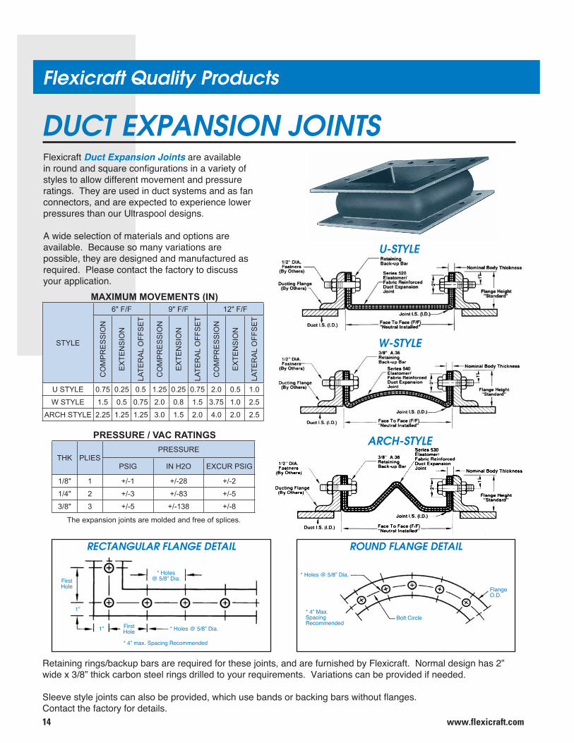
DUCT EXPANSION JOINTSFlexicraft Duct Expansion Joints are available in round and square configurations in a variety of styles to allow different movement and pressure ratings. They are used in duct systems and as fan connectors, and are expected to experience lower pressures than our Ultraspool designs.
A wide selection of materials and options are available. Because so many variations are possible, they are designed and manufactured as required. Please contact the factory to discuss your application.
Retaining rings/backup bars are required for these joints, and are furnished by Flexicraft. Normal design has 2” wide x 3/8” thick carbon steel rings drilled to your requirements. Variations can be provided if needed.
Sleeve style joints can also be provided, which use bands or backing bars without flanges. Contact the factory for details.
* Holes@ 5/8” Dia.First
Hole
1”
1” FirstHole
* 4” max. Spacing Recommended
* Holes @ 5/8” Dia.
RECTANGULAR FLANGE DETAIL
* 4” Max.SpacingRecommended
* Holes @ 5/8” Dia.
Bolt Circle
Flange O.D.
ROUND FLANGE DETAIL
STYLE
6" F/F 9" F/F 12" F/F
CO
MP
RE
SS
ION
EX
TEN
SIO
N
LATE
RA
L O
FFS
ET
CO
MP
RE
SS
ION
EX
TEN
SIO
N
LATE
RA
L O
FFS
ET
CO
MP
RE
SS
ION
EX
TEN
SIO
N
LATE
RA
L O
FFS
ET
U STYLE 0.75 0.25 0.5 1.25 0.25 0.75 2.0 0.5 1.0
W STYLE 1.5 0.5 0.75 2.0 0.8 1.5 3.75 1.0 2.5
ARCH STYLE 2.25 1.25 1.25 3.0 1.5 2.0 4.0 2.0 2.5
THK PLIESPRESSURE
PSIG IN H2O EXCUR PSIG
1/8" 1 +/-1 +/-28 +/-2
1/4" 2 +/-3 +/-83 +/-5
3/8" 3 +/-5 +/-138 +/-8
MAXIMUM MOVEMENTS (IN)
PRESSURE / VAC RATINGS
The expansion joints are molded and free of splices.
U-STYLE
ARCH-STYLE
W-STYLE
15www.flexicraft.com
Flexicraft Quality Products
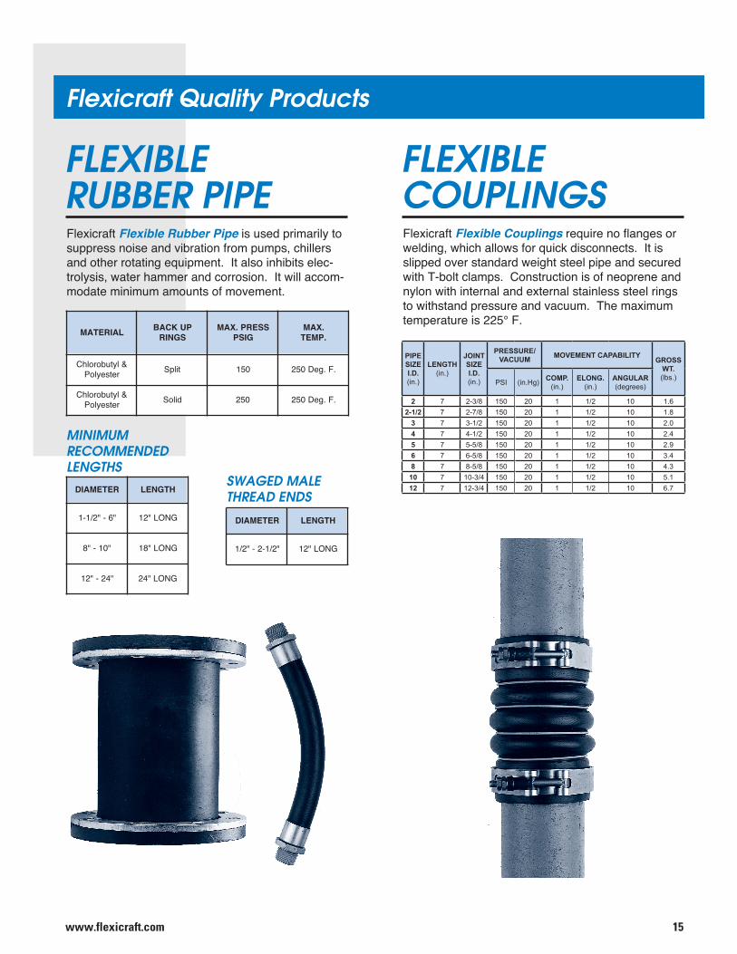
FLEXIBLERUBBER PIPEFlexicraft Flexible Rubber Pipe is used primarily to suppress noise and vibration from pumps, chillers and other rotating equipment. It also inhibits elec-trolysis, water hammer and corrosion. It will accom-modate minimum amounts of movement.
RETEMAID HTGNEL
"6-"2/1-1 GNOL"21
"01-"8 GNOL"81
"42-"21 GNOL"42
LAIRETAM PUKCABSGNIR
SSERP.XAMGISP
.XAM.PMET
&lytuborolhCretseyloP tilpS 051 .F.geD052
&lytuborolhCretseyloP diloS 052 .F.geD052
RETEMAID HTGNEL
"2/1-2-"2/1 GNOL"21
FLEXIBLECOUPLINGSFlexicraft Flexible Couplings require no flanges or welding, which allows for quick disconnects. It is slipped over standard weight steel pipe and secured with T-bolt clamps. Construction is of neoprene and nylon with internal and external stainless steel rings to withstand pressure and vacuum. The maximum temperature is 225° F.
MINIMUM RECOMMENDED LENGTHS
SWAGED MALETHREAD ENDS
PIPESIZEI.D.(in.)
LENGTH(in.)
JOINTSIZEI.D.(in.)
PRESSURE/VACUUM MOVEMENT CAPABILITY GROSS
WT.(lbs.)
PSI (in.Hg) COMP.(in.)
ELONG.(in.)
ANGULAR(degrees)
2 7 2-3/8 150 20 1 1/2 10 1.62-1/2 7 2-7/8 150 20 1 1/2 10 1.8
3 7 3-1/2 150 20 1 1/2 10 2.04 7 4-1/2 150 20 1 1/2 10 2.45 7 5-5/8 150 20 1 1/2 10 2.96 7 6-5/8 150 20 1 1/2 10 3.48 7 8-5/8 150 20 1 1/2 10 4.3
10 7 10-3/4 150 20 1 1/2 10 5.112 7 12-3/4 150 20 1 1/2 10 6.7
www.flexicraft.com16
Flexicraft Quality Products
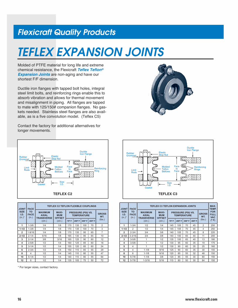
TEFLEX EXPANSION JOINTSMolded of PTFE material for long life and extreme chemical resistance, the Flexicraft Teflex Teflon® Expansion Joints are non-aging and have our shortest F/F dimension.
Ductile iron flanges with tapped bolt holes, integral steel limit bolts, and reinforcing rings enable this to absorb vibration and allows for thermal movement and misalignment in piping. All flanges are tapped to mate with 125/150# companion flanges. No gas-kets needed. Stainless steel flanges are also avail-able, as is a five convolution model. (Teflex C5)
Contact the factory for additional alternatives for longer movements.
ElasticStop NutRubber
Grommet
MoldedTeflonBellows
Faceto
Face
Gasket
SizeI.D.
ReinforcingRings
DuctileIron Flange
LimitRods
TEFLEX C3
ElasticStop NutRubber
Grommet
MoldedTeflonBellows
Faceto
Face
GasketSizeI.D.
ReinforcingRing
DuctileIron Flange
LimitRods
TEFLEX C2
* For larger sizes, contact factory.
JOINTSIZEI.D.(in.)*
FACETO
FACE(in.)
TEFLEX C2 TEFLON FLEXIBLE COUPLINGS
MAXIMUMAXIAL
TRANSVERSE(±in.)
MAXI-MUM
OFFSET(±in.)
PRESSURE (PSI) VS.TEMPERATURE GROSS
WT.(lbs.)
70º F 200º F 300º F 400º F
1 1-3/8 1/4 1/8 170 135 100 70 21-1/2 1-3/8 1/4 1/8 170 135 100 70 3
2 1-9/16 1/4 1/8 170 135 95 65 72-1/2 2-1/4 5/16 1/8 165 130 95 65 10
3 2-1/4 3/8 3/16 165 125 90 60 124 2-5/8 1/2 1/4 160 125 85 60 185 3-1/4 1/2 1/4 155 120 85 60 246 2-3/4 1/2 1/4 150 115 85 55 298 4 1/2 1/4 145 110 80 55 4710 5-1/4 1/2 1/4 140 110 80 55 6412 6 1/2 1/4 135 105 75 50 72
JOINTSIZEI.D.(in.)*
FACETO
FACE(in.)
TEFLEX C3 TEFLON EXPANSION JOINTS MAX.TEMP.FORFULLVAC(º F)
MAXIMUMAXIAL
TRANSVERSE(±in.)
MAXI-MUM
OFFSET(±in.)
PRESSURE (PSI) VS.TEMPERATURE GROSS
WT.(lbs.)
70º F 200º F 300º F 400º F
1 1-3/4 1/2 1/4 145 105 70 45 2 2501-1/2 2 1/2 1/4 145 105 70 45 4 250
2 2-3/4 3/4 3/8 140 105 70 45 8 2202-1/2 3-3/16 3/4 3/8 140 100 65 40 11 200
3 3-5/8 1 1/2 135 100 65 40 13 1804 3-5/8 1 1/2 130 95 60 35 19 1755 4 1 1/2 130 90 60 35 25 1606 4 1-1/8 9/16 125 90 60 35 30 1558 6 1-1/8 9/16 120 85 55 32 48 150
10 5-7/8 1-1/8 3/8 120 85 55 30 80 15012 5-7/8 1-3/16 5/16 115 80 50 30 84 150
17www.flexicraft.com
Performance Characteristics
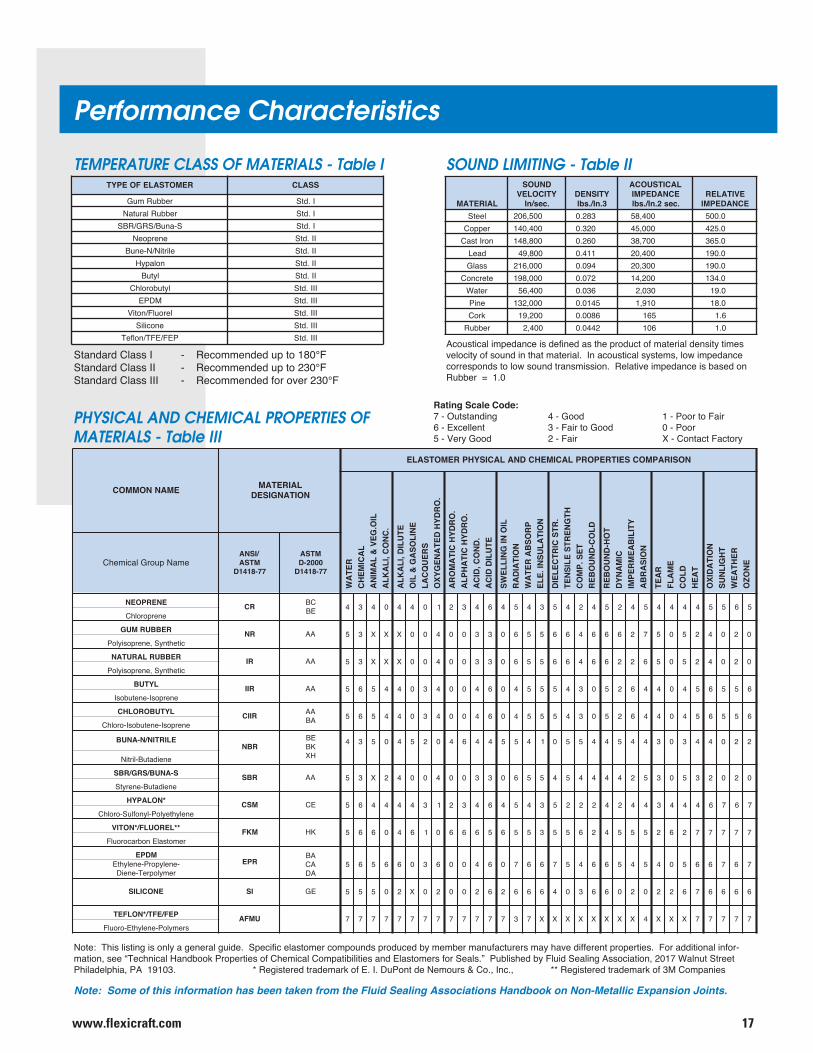
SOUND LIMITING - Table IIREMOTSALEFOEPYT SSALC
rebbuRmuG I.dtSrebbuRlarutaN I.dtSS-anuB/SRG/RBS I.dtS
enerpoeN II.dtSelirtiN/N-enuB II.dtS
nolapyH II.dtSlytuB II.dtS
lytuborolhC III.dtSMDPE III.dtS
leroulF/notiV III.dtSenociliS III.dtS
PEF/EFT/nolfeT III.dtS
Note: Some of this information has been taken from the Fluid Sealing Associations Handbook on Non-Metallic Expansion Joints.
LAIRETAM
DNUOSYTICOLEV.ces/nI
YTISNED3.nI/.sbl
LACITSUOCAECNADEPMI.ces2.nI/.sbl
EVITALERECNADEPMI
leetS 005,602 382.0 004,85 0.005reppoC 004,041 023.0 000,54 0.524norItsaC 008,841 062.0 007,83 0.563
daeL 008,94 114.0 004,02 0.091ssalG 000,612 490.0 003,02 0.091etercnoC 000,891 270.0 002,41 0.431retaW 004,65 630.0 030,2 0.91eniP 000,231 5410.0 019,1 0.81kroC 002,91 6800.0 561 6.1rebbuR 004,2 2440.0 601 0.1
Standard Class I - Recommended up to 180°FStandard Class II - Recommended up to 230°FStandard Class III - Recommended for over 230°F
Acoustical impedance is defined as the product of material density times velocity of sound in that material. In acoustical systems, low impedance corresponds to low sound transmission. Relative impedance is based on Rubber = 1.0
PHYSICAL AND CHEMICAL PROPERTIES OF MATERIALS - Table III
Note: This listing is only a general guide. Specific elastomer compounds produced by member manufacturers may have different properties. For additional infor-mation, see “Technical Handbook Properties of Chemical Compatibilities and Elastomers for Seals.” Published by Fluid Sealing Association, 2017 Walnut Street Philadelphia, PA 19103. * Registered trademark of E. I. DuPont de Nemours & Co., Inc., ** Registered trademark of 3M Companies
Rating Scale Code:7 - Outstanding 4 - Good 1 - Poor to Fair6 - Excellent 3 - Fair to Good 0 - Poor5 - Very Good 2 - Fair X - Contact Factory
TEMPERATURE CLASS OF MATERIALS - Table I
EMANNOMMOC LAIRETAMNOITANGISED
NOSIRAPMOCSEITREPORPLACIMEHCDNALACISYHPREMOTSALE
emaNpuorGlacimehC/ISNAMTSA77-8141D
MTSA0002-D77-8141D
ENERPOEN RC CB 4 3 4 0 4 4 0 1 2 3 4 6 4 5 4 3 5 4 2 4 5 2 4 5 4 4 4 4 5 5 6 5enerporolhC EB
REBBURMUG RN AA 5 3 X X X 0 0 4 0 0 3 3 0 6 5 5 6 6 4 6 6 6 2 7 5 0 5 2 4 0 2 0citehtnyS,enerposiyloP
REBBURLARUTAN RI AA 5 3 X X X 0 0 4 0 0 3 3 0 6 5 5 6 6 4 6 6 2 2 6 5 0 5 2 4 0 2 0citehtnyS,enerposiyloP
LYTUB RII AA 5 6 5 4 4 0 3 4 0 0 4 6 0 4 5 5 5 4 3 0 5 2 6 4 4 0 4 5 6 5 5 6enerposI-enetubosI
LYTUBOROLHC RIIC AA 5 6 5 4 4 0 3 4 0 0 4 6 0 4 5 5 5 4 3 0 5 2 6 4 4 0 4 5 6 5 5 6enerposI-enetubosI-orolhC AB
ELIRTIN/N-ANUBRBN
EBKBHX
4 3 5 0 4 5 2 0 4 6 4 4 5 5 4 1 0 5 5 4 4 5 4 4 3 0 3 4 4 0 2 2
eneidatuB-lirtiN
S-ANUB/SRG/RBS RBS AA 5 3 X 2 4 0 0 4 0 0 3 3 0 6 5 5 4 5 4 4 4 4 2 5 3 0 5 3 2 0 2 0eneidatuB-enerytS
*NOLAPYH MSC EC 5 6 4 4 4 4 3 1 2 3 4 6 4 5 4 3 5 2 2 2 4 2 4 4 3 4 4 4 6 7 6 7enelyhteyloP-lynofluS-orolhC
**LEROULF/*NOTIV MKF KH 5 6 6 0 4 6 1 0 6 6 6 5 6 5 5 3 5 5 6 2 4 5 5 5 2 6 2 7 7 7 7 7remotsalEnobracoroulF
MDPERPE
ABACAD
5 6 5 6 6 0 3 6 0 0 4 6 0 7 6 6 7 5 4 6 6 5 4 5 4 0 5 6 6 7 6 7-enelyporP-enelyhtEremylopreT-eneiD
ENOCILIS IS EG 5 5 5 0 2 X 0 2 0 0 2 6 2 6 6 6 4 0 3 6 6 0 2 0 2 2 6 7 6 6 6 6
PEF/EFT/*NOLFET UMFA 7 7 7 7 7 7 7 7 7 7 7 7 7 3 7 X X X X X X X X 4 X X X 7 7 7 7 7sremyloP-enelyhtE-oroulF
WA
TER
CH
EMIC
AL
AN
IMA
L &
VEG
.OIL
ALK
ALI
, CO
NC
.
ALK
ALI
, DIL
UTE
OIL
& G
ASO
LIN
ELA
CQ
UER
SO
XYG
ENA
TED
HYD
RO
.
AR
OM
ATI
C H
YDR
O.
ALP
HA
TIC
HYD
RO
.A
CID
, CO
ND
.A
CID
DIL
UTE
SWEL
LIN
G IN
OIL
RA
DIA
TIO
NW
ATE
R A
BSO
RP
ELE.
INSU
LATI
ON
DIE
LEC
TRIC
STR
.TE
NSI
LE S
TREN
GTH
CO
MP.
SET
REB
OU
ND
-CO
LD
REB
OU
ND
-HO
TD
YNA
MIC
IMPE
RM
EAB
ILIT
YA
BR
ASI
ON
TEA
RFL
AM
EC
OLD
HEA
T
OXI
DA
TIO
NSU
NLI
GH
TW
EATH
ERO
ZON
E
www.flexicraft.com18
Construction Details
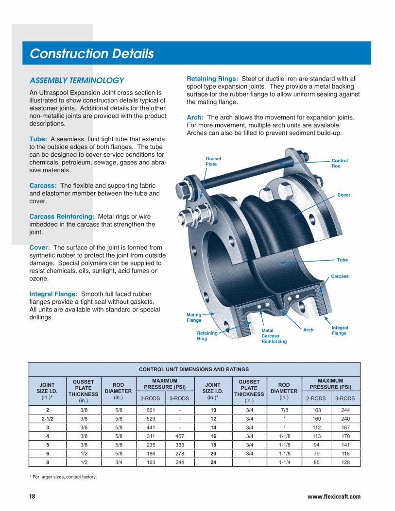
ASSEMBLY TERMINOLOGYAn Ultraspool Expansion Joint cross section is illustrated to show construction details typical of elastomer joints. Additional details for the other non-metallic joints are provided with the product descriptions.
Tube: A seamless, fluid tight tube that extends to the outside edges of both flanges. The tube can be designed to cover service conditions for chemicals, petroleum, sewage, gases and abra-sive materials.
Carcass: The flexible and supporting fabric and elastomer member between the tube and cover.
Carcass Reinforcing: Metal rings or wire imbedded in the carcass that strengthen the joint.
Cover: The surface of the joint is formed from synthetic rubber to protect the joint from outside damage. Special polymers can be supplied to resist chemicals, oils, sunlight, acid fumes or ozone.
Integral Flange: Smooth full faced rubber flanges provide a tight seal without gaskets. All units are available with standard or special drillings.
* For larger sizes, contact factory.
Retaining Rings: Steel or ductile iron are standard with all spool type expansion joints. They provide a metal backing surface for the rubber flange to allow uniform sealing against the mating flange.
Arch: The arch allows the movement for expansion joints. For more movement, multiple arch units are available. Arches can also be filled to prevent sediment build-up.
MetalCarcassReinforcing
ArchRetaining Ring
MatingFlange
IntegralFlange
Carcass
Tube
Cover
ControlRod
GussetPlate
CONTROL UNIT DIMENSIONS AND RATINGS
JOINTSIZE I.D.
(in.)*
GUSSETPLATE
THICKNESS(in.)
RODDIAMETER
(in.)
MAXIMUMPRESSURE (PSI) JOINT
SIZE I.D.(in.)*
GUSSETPLATE
THICKNESS(in.)
RODDIAMETER
(in.)
MAXIMUMPRESSURE (PSI)
2-RODS 3-RODS 2-RODS 3-RODS
2 3/8 5/8 661 - 10 3/4 7/8 163 244
2-1/2 3/8 5/8 529 - 12 3/4 1 160 240
3 3/8 5/8 441 - 14 3/4 1 112 167
4 3/8 5/8 311 467 16 3/4 1-1/8 113 170
5 3/8 5/8 235 353 18 3/4 1-1/8 94 141
6 1/2 5/8 186 278 20 3/4 1-1/8 79 118
8 1/2 3/4 163 244 24 1 1-1/4 85 128
19www.flexicraft.com
Construction Details
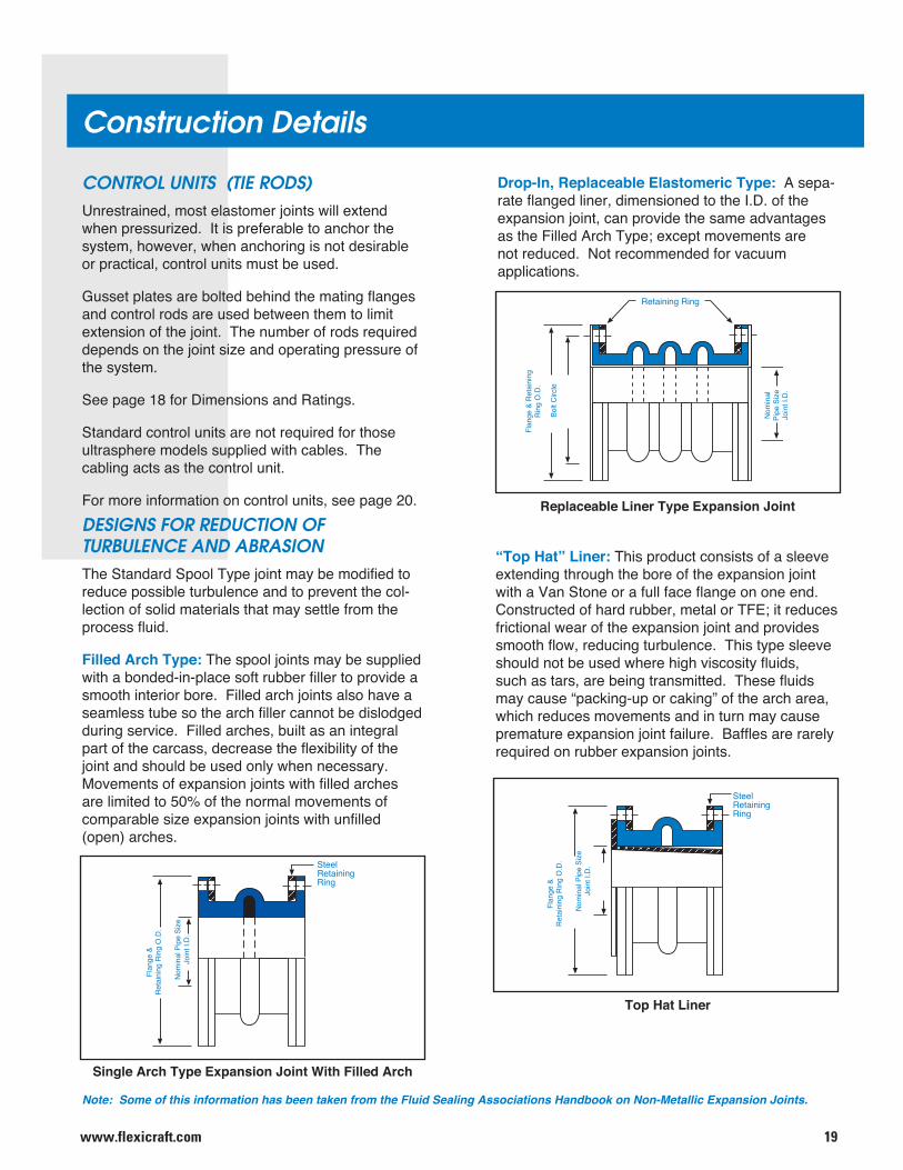
DESIGNS FOR REDUCTION OF TURBULENCE AND ABRASIONThe Standard Spool Type joint may be modified to reduce possible turbulence and to prevent the col-lection of solid materials that may settle from the process fluid.
Filled Arch Type: The spool joints may be supplied with a bonded-in-place soft rubber filler to provide a smooth interior bore. Filled arch joints also have a seamless tube so the arch filler cannot be dislodged during service. Filled arches, built as an integral part of the carcass, decrease the flexibility of the joint and should be used only when necessary. Movements of expansion joints with filled arches are limited to 50% of the normal movements of comparable size expansion joints with unfilled (open) arches.
Drop-In, Replaceable Elastomeric Type: A sepa-rate flanged liner, dimensioned to the I.D. of the expansion joint, can provide the same advantages as the Filled Arch Type; except movements are not reduced. Not recommended for vacuum applications.
Note: Some of this information has been taken from the Fluid Sealing Associations Handbook on Non-Metallic Expansion Joints.
“Top Hat” Liner: This product consists of a sleeve extending through the bore of the expansion joint with a Van Stone or a full face flange on one end. Constructed of hard rubber, metal or TFE; it reduces frictional wear of the expansion joint and provides smooth flow, reducing turbulence. This type sleeve should not be used where high viscosity fluids, such as tars, are being transmitted. These fluids may cause “packing-up or caking” of the arch area, which reduces movements and in turn may cause premature expansion joint failure. Baffles are rarely required on rubber expansion joints.
CONTROL UNITS (TIE RODS)Unrestrained, most elastomer joints will extend when pressurized. It is preferable to anchor the system, however, when anchoring is not desirable or practical, control units must be used.
Gusset plates are bolted behind the mating flanges and control rods are used between them to limit extension of the joint. The number of rods required depends on the joint size and operating pressure of the system.
See page 18 for Dimensions and Ratings.
Standard control units are not required for those ultrasphere models supplied with cables. The cabling acts as the control unit.
For more information on control units, see page 20.
SteelRetainingRing
Nom
inal
Pip
e Si
zeJo
int I
.D.
Flan
ge &
R
etai
ning
Rin
g O
.D.
SteelRetainingRing
Nom
inal
Pip
e Si
zeJo
int I
.D.
Flan
ge &
R
etai
ning
Rin
g O
.D.
Retaining Ring
Bolt
Circ
le
Flan
ge &
Ret
aini
ngR
ing
O.D
.
Nom
inal
Pi
pe S
ize
Join
t I.D
.
Top Hat Liner
Replaceable Liner Type Expansion Joint
Single Arch Type Expansion Joint With Filled Arch
www.flexicraft.com20
Installation
Note: Some of this information has been taken from the Fluid Sealing Associations Handbook on Non-Metallic Expansion Joints.
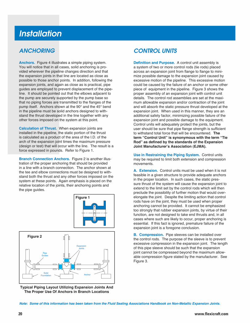
Anchors. Figure 4 illustrates a simple piping system. You will notice that in all cases, solid anchoring is pro-vided wherever the pipeline changes direction and that the expansion joints in that line are located as close as possible to those anchor points. In addition, following the expansion joints, and again as close as is practical, pipe guides are employed to prevent displacement of the pipe-line. It should be pointed out that the elbows adjacent to the pump are securely supported by the pump base so that no piping forces are transmitted to the flanges of the pump itself. Anchors shown at the 90° and the 45° bend in the pipeline must be solid anchors designed to with-stand the thrust developed in the line together with any other forces imposed on the system at this point.
Calculation of Thrust. When expansion joints are installed in the pipeline, the static portion of the thrust is calculated as a product of the area of the I.D. of the arch of the expansion joint times the maximum pressure (design or test) that will occur with the line. The result is a force expressed in pounds. Refer to Figure 1.
Branch Connection Anchors. Figure 2 is another illus-tration of the proper anchoring that should be provided in a line with a branch connection. The anchor shown at the tee and elbow connections must be designed to with-stand both the thrust and any other forces imposed on the system at these points. Again emphasis is placed on the relative location of the joints, their anchoring points and the pipe guides.
ANCHORING
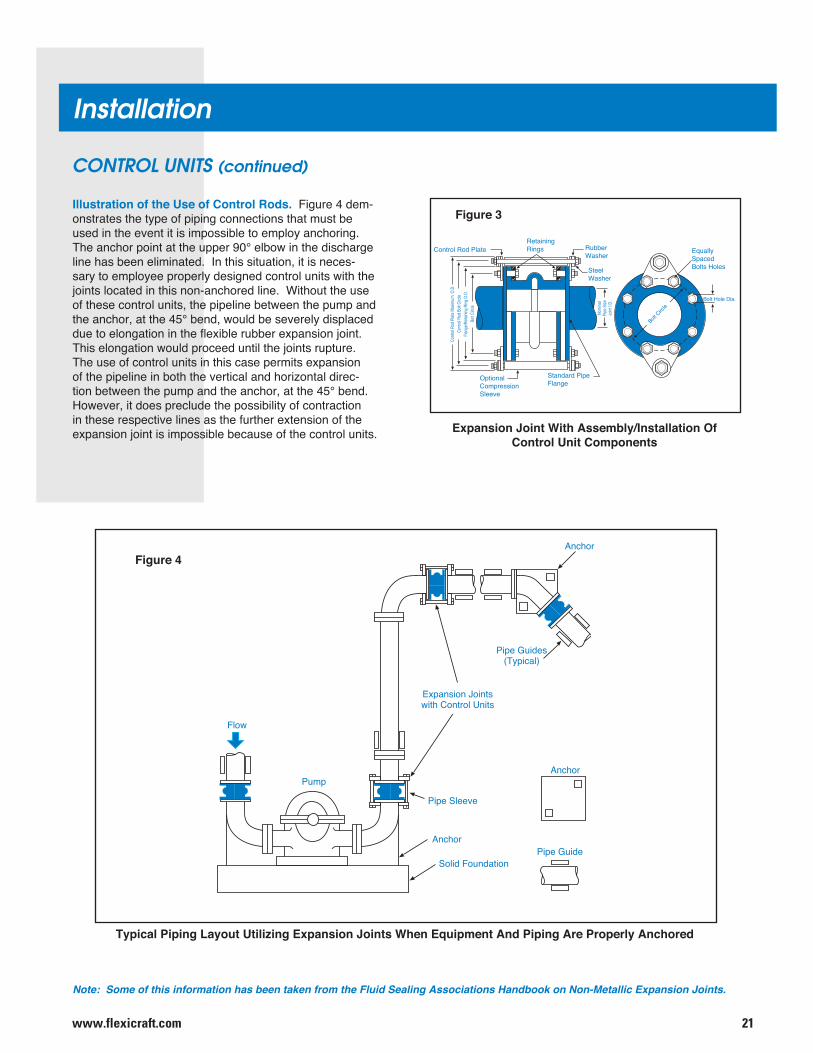
Definition and Purpose. A control unit assembly is a system of two or more control rods (tie rods) placed across an expansion joint from flange to flange to mini-mize possible damage to the expansion joint caused by excessive motion of the pipeline. This excessive motion could be caused by the failure of an anchor or some other piece of equipment in the pipeline. Figure 3 shows the proper assembly of an expansion joint with control unit details. The control rod assemblies are set at the maxi-mum allowable expansion and/or contraction of the joint and will absorb the static pressure thrust developed at the expansion joint. When used in this manner, they are an additional safety factor, minimizing possible failure of the expansion joint and possible damage to the equipment. Control units will adequately protect the joints, but the user should be sure that pipe flange strength is sufficient to withstand total force that will be encountered. The term “Control Unit” is synonymous with the term “Tie Rod” as defined by the standards of the Expansion Joint Manufacturer’s Association (EJMA).
Use in Restraining the Piping System. Control units may be required to limit both extension and compression movements.
A. Extension. Control units must be used when it is not feasible in a given structure to provide adequate anchors in the proper location. In such cases, the static pres-sure thrust of the system will cause the expansion joint to extend to the limit set by the control rods which will then preclude the possibility of further motion that would over-elongate the joint. Despite the limiting action that control rods have on the joint, they must be used when proper anchoring cannot be provided. It cannot be emphasized too strongly that rubber expansion joints, by virtue of their function, are not designed to take end thrusts and, in all cases where such are likely to occur, proper anchoring is essential. If this fact is ignored, premature failure of the expansion joint is a foregone conclusion.
B. Compression. Pipe sleeves can be installed over the control rods. The purpose of the sleeve is to prevent excessive compression in the expansion joint. The length of this pipe sleeve should be such that the expansion joint cannot be compressed beyond the maximum allow-able compression figure stated by the manufacturer. See Figure 3.
CONTROL UNITS
D
ExpansionJoints
PipeGuides
SolidFoundation Anchor
Typical Piping Layout Utilizing Expansion Joints And The Proper Use Of Anchors in Branch Locations
Figure 1
Figure 2
21www.flexicraft.com
Installation
Note: Some of this information has been taken from the Fluid Sealing Associations Handbook on Non-Metallic Expansion Joints.
CONTROL UNITS (continued)
Illustration of the Use of Control Rods. Figure 4 dem-onstrates the type of piping connections that must be used in the event it is impossible to employ anchoring. The anchor point at the upper 90° elbow in the discharge line has been eliminated. In this situation, it is neces-sary to employee properly designed control units with the joints located in this non-anchored line. Without the use of these control units, the pipeline between the pump and the anchor, at the 45° bend, would be severely displaced due to elongation in the flexible rubber expansion joint. This elongation would proceed until the joints rupture. The use of control units in this case permits expansion of the pipeline in both the vertical and horizontal direc-tion between the pump and the anchor, at the 45° bend. However, it does preclude the possibility of contraction in these respective lines as the further extension of the expansion joint is impossible because of the control units.
Expansion Jointswith Control Units
Contr
ol Ro
d Plat
e Max
imum
O.D
.Co
ntrol
Rod B
olt C
ircle
Flang
e/Reta
ining
Ring
O.D
.Bo
lt Circ
le
Control Rod Plate RubberWasher
SteelWasher
RetainingRings
Nomi
nal
Pipe S
izeJo
int I.D
.
Standard PipeFlange
OptionalCompressionSleeve
EquallySpacedBolts Holes
Bolt Hole Dia.
Bolt Circ
le
Expansion Joint With Assembly/Installation Of Control Unit Components
Typical Piping Layout Utilizing Expansion Joints When Equipment And Piping Are Properly Anchored
Pipe Guides(Typical)
Anchor
Pipe Sleeve
Anchor
Solid Foundation
Anchor
Pipe Guide
Pump
Flow
Figure 4
Figure 3
www.flexicraft.com22
Terms and Conditions1. All quotations are subject to approval,acceptance and correction at the home officeAny errors in quotations resulting in orders will becorrected and re-submitted to the customer fortheir acceptance or refusal.
No prices may be made up from information otherthan that shown in the tables.
2. All prices are F.O.B. factory, Chicago, Illinois,are are quoted exclusive of any taxes.
Shipments boxed for trans-ocean export add10% to total trade price.
Terms: Net 30 days from date of invoice.
3. Cancellation or alteration of an order or returnof any product by Buyer may not be made without advance written consent of manufacturer andshall be subjected to a cancellation charge.
A 35% minimum restocking charge shall beplaced on any returned goods of stocked items. Fabricated items are not returnable.
4. We will not be responsible for delays inshipping due to conditions beyond our controlsuch as strikes, fires, or accidents.
5. Any claims for shortages or damagedproducts must be made in writing within 10 daysafter receipt of shipment.
6. Prices subject to change without notice.
Design and Dimensional SpecificationsThe products illustrated reflect the designcharacteristics at time of printing. Flexicraft reserves the right to changedimensions, materials, or methods of constructionwithout notice. Please contact the factory forcertified prints (exact dimensions) whennecessary.
Limited WarrantyAll products are warranted to be free of defects inmaterial and workmanship for a period of oneyear from the date of shipment, subject to thelimitations below.
If the purchaser believes a product is defectivethe purchaser shall: (a) Notify the manufacturer,state the alleged defect and request permission toreturn the product. (b) If permission given, returnthe product with transportation prepaid. If theproduct is accepted for return and found to bedefective, the manufacturer will, at its discretion,either repair or replace the product F.O.B. factory,within 60 days of receipt, or refund the purchaseprice. Other than to repair, replace or refund asdescribed above, purchaser agrees thatmanufacturer shall not be liable for any loss,
costs, expenses or damages of any kind arisingout of the product, its use, installation orreplacement, labeling, instructions, information ortechnical data of any kind, description of productor use, sample or model, warnings or lack of anyof the foregoing. NO OTHER WARRANTIES,WRITTEN OR ORAL, EXPRESS OR IMPLIED,INCLUDING THE WARRANTIES OF FITNESSFOR A PARTICULAR PURPOSE ANDMERCHANTABILITY, ARE MADE ORAUTHORIZED. NO AFFIRMATION OF FACT,PROMISE, DESCRIPTION OF PRODUCT OFUSE OR SAMPLE OR MODEL SHALL CREATEANY WARRANTY FROM THE MANUFACTURER,UNLESS SIGNED BY THE PRESIDENT OFMANUFACTURER. These products are notmanufactured, sold or intended for personal,family or household purposes.

23www.flexicraft.com
Catalog NMEJ12 Copyright© FLEXICRAFT IND. 2012, All rights reserved Printed in U.S.A.
2315 West Hubbard Street, Chicago, Illinois 60612, Telephone 800-533-1024, 312-738-3588, Fax 312-421-6327www.flexicraft.com [email protected]
Distributed by:


![[PPT]Pipe Materials and Types of Joints - Home - Sri ... · Web viewTypes of pipe materials Metallic Pipes : Unlined metallic pipes – Cast Iron(C.I) Galvanized Iron(G.I) Mild Steel(M.S)](https://img.pdfslide.us/doc/110x75/5b06eed77f8b9ae9628db627/pptpipe-materials-and-types-of-joints-home-sri-viewtypes-of-pipe-materials.jpg)