Embed Size (px)
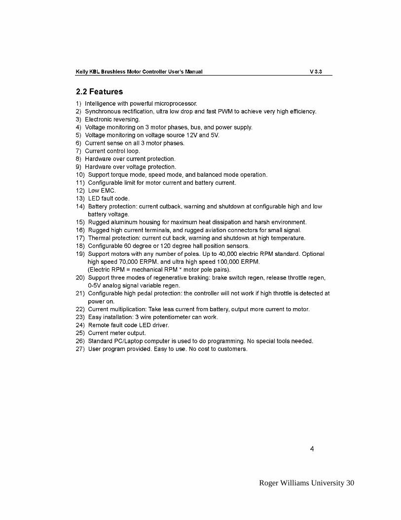
Citation preview
#8
RWU SOLAR SPLASH Team Members: Kristen Neff | ME | Team Captain Darren McCall | ME Daniel Wisniewski | CE Contributors/Past Team Members: Connor Adams | ME Andrew Carlson | ME Jared Delfin | ME Nicholas Benoit | EE Abdulrahim Hasan | EE Rei Medina | ME
Academic Advisor: Dr. Charles Thangaraj
Other Advisors:
Dr. Anthony Ruocco Dr. Benjamin McPheron
Submitted May 9, 2016
Roger Williams University 1
I. Executive Summary
Roger Williams University has entered the 2016 Solar Splash competition as a rookie team with
a boat that is the product of two years’ effort. The creation of this boat was the study of the
undergraduate Senior Design class for both the 2014-2015 and the 2015-2016 school years. The
main product of the 2014-2015 team was to design and build the hull of the boat with an entirely
new and unique design. The current team, the 2015-2016 team worked to design the systems to
power and drive the boat so that it functions efficiently. This year’s team originally started out
with four members, three mechanical engineers and a computer engineer. During the fall
semester, the team focused on the design, purchasing, and assembly of the solar system, as well
as the preliminary designs and the purchasing of materials for the rest of the electrical and
driving systems for the boat. The spring semester mainly focused on the assembly and testing of
these designs to ensure that the boat would be ready for the competition in June.
A complication arose in the spring which caused one mechanical engineer to leave the team,
reducing it in size to a three person team. The remaining team members focused on refining the
designs of the previous semester, including reducing the weight and complexity of the solar
panel connections. Another focus of the semester was coming up with the different
configurations of the boat for different races, including connecting a second set of batteries for
the Endurance Event. The hull of the boat was repainted in order to reduce the drag it would
create and a new and unique steering system was designed for precise and quick maneuverability
around turns. These, along with other design refinements have improved boat handling for the
competition.
The solar panel setup consists of eight 60 W panels in order to obtain the exact value of 480 W
charging capability. The panels are inflexible monocrystalline panels, connected to the three
Optima yellow-top batteries via Renogy charge controllers. The batteries are connected in series
to a Kelly KBL motor controller which powers a Moto-energy motor directly connected to the
driveshaft. The entire design was kept simple due to the fact that this is the first year of
competition.
Through the process of designing and creating a fully functional solar/electric boat this team has
gained new skills and appreciation for the field of engineering. Despite not having an electrical
engineer as a team member, with advice from faculty we have been able to fully design and build
a boat that will be very competitive in this year’s Solar Splash competition.
Roger Williams University 2
Table of Contents I. Executive Summary ..................................................................................................................... 1
II. Overall Project Objectives ......................................................................................................... 3
III. Solar System Design ................................................................................................................. 3
IV. Electrical System ...................................................................................................................... 4
V. Power Electronics System .......................................................................................................... 5
VI. Hull Design ............................................................................................................................... 6
VII. Drive Train and Steering ......................................................................................................... 8
VIII. Data Acquisition and/or Communications ............................................................................. 9
IX. Project Management ................................................................................................................. 9
A. Team members and leadership roles: ............................................................................... 9
B. Project Planning and Schedule ......................................................................................... 9
C. Financial and Fundraising .............................................................................................. 10
D. Strategy for team continuity and sustainability .............................................................. 10
E. Discussion and Self-Evaluation ..................................................................................... 10
X. Conclusions and Recommendations ........................................................................................ 10
XI. References............................................................................................................................... 11
XII. Appendices ............................................................................................................................ 13
Appendix A: Battery Documentation ....................................................................................... 13
Appendix B: Flotation Calculations.......................................................................................... 16
Appendix C: Proof of Insurance ............................................................................................... 17
Appendix D: Team Roster ........................................................................................................ 18
Appendix E: The G-code used to create the steering mechanism ............................................ 19
G-code for the base mount of steering assembly .................................................................. 19
G-code for the motor mount of steering assembly................................................................ 19
Appendix F: Specification Sheets ............................................................................................. 21
Appendix G: Driveshaft Calculations ....................................................................................... 33

Roger Williams University 3
II. Overall Project Objectives
Because the Roger Williams Solar Splash team is a rookie team this year, the project objectives
were kept simple. Primarily, the team’s goal is to qualify and participate competitively in the
2016 Solar Splash competition. Along with this, the team has focused on designing with the
Endurance Event as the race to focus on when making design decisions. The goal for the top
speed of the boat was to hit twenty-five miles per hour with the use of only one motor. Many of
the components used for this year’s competition were purchased by a previous Roger Williams
Solar Splash team which never made it to competition. In order to conserve money this year the
team also set an objective to use as many previously purchased parts as possible in the overall
design of the boat.
III. Solar System Design
For our current design, the team purchased eight 60 Watt solar panels to exactly meet the 480
Watt maximum allowance in the competition guidelines. We chose Alecko rigid
monocrystalline solar panels instead of flexible cells because they perform at a higher efficiency.
The solar panels are split in a 3:3:2 ratio for configuration for charging the three batteries (see
Figure 1 below). Each set is wired to their own Renogy 30 amp PWM charge controller using
MC4 connectors and 8-gauge wire. A 10 amp fast blow fuse inside a waterproof AGU fuse
holder is connected from each of the charge controller to a 12 volt battery to protect the system
in the event of excess current. The three batteries are connected in series with a 36-volt output
using 4-gauge audio wire and InstallGear battery terminals. This design gives us a larger fall
tolerance then a design consisting of a single charge controller. If something were to happen one
of our charge controller, the whole system would not go offline, instead only a single set of the
solar panels would stop charging the batteries.
Figure 1: Diagram of the solar panel configuration and how the panels are wired to the batteries.
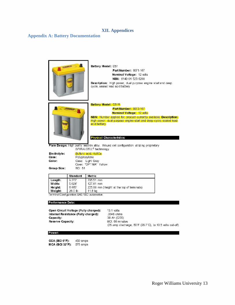
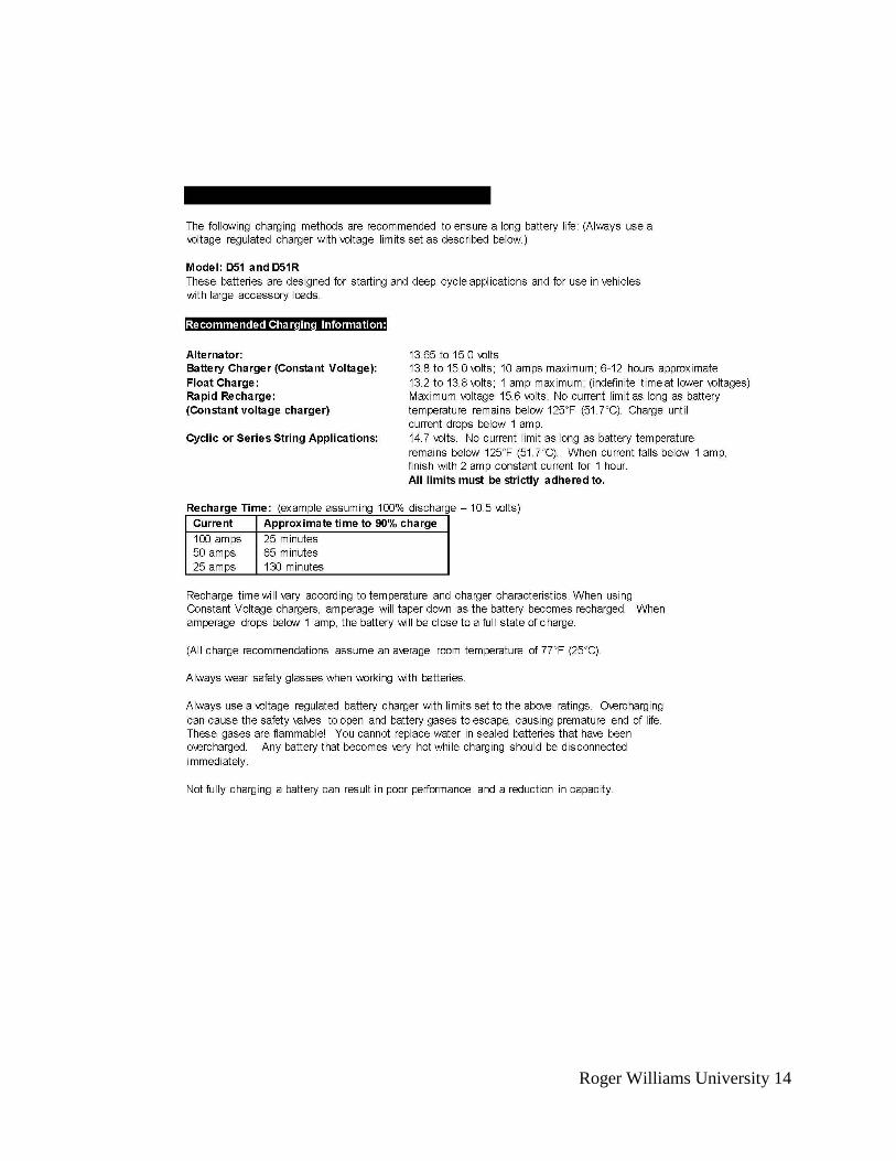
The batteries used are Optima Yellow Top D51R with ratings of both twelve Volts and 38 Ah
which were one of the components used that had been previously purchased.

Roger Williams University 4
The layout of the solar panels to the boat can be seen in Figure _ below, where the 3:3:2 ratio is
clearly seen. For ease of attachment and removal the panels on the sides of the boat are bolted
together, then connected by U-brackets to the outrigger supports. The two panels on the back of
the boat are bolted directly onto the back of the boat using L-brackets.
Figure 2: Image of the solar panel layout when mechanically fastened to the boat.
IV. Electrical System
The complete electrical system, as seen in Figure 3, is an extension of the solar power system
described in the previous section.
The motor we used was a tri-phase brushless DC motor - Moto-Energy 0913. This motor was
purchased by last year’s team but was never tested or used. Instead of purchasing a new motor
we decided to adapt the motor into our electrical system due to the fact that the motor itself
offers a high efficiency (above 90%) for voltages for a wide range of voltages. This motor could
prove to be advantageous over a multi-motor system in the sprint event due to its high power to
weight ratio.
Three Optima Yellow Top D51R batteries were connected in series that produced a maximum
overall output voltage of 36 volts. The D51Rs were chosen for the endurance and sprint events
because they are deep cycle and an offer high efficiency in fast discharging applications. Each
battery weighs 26 pounds, which meets the weight requirement, and has a nominal voltage of 12
volts with a capacity of 38 Ah. We also bought three Might Max batteries as a back-up set if
anything happens to the D51R’s. These batteries are deep cycle and offer a nominal voltage of
12 volts with a capacity of 35 Ah and weigh 8.38 pounds each.
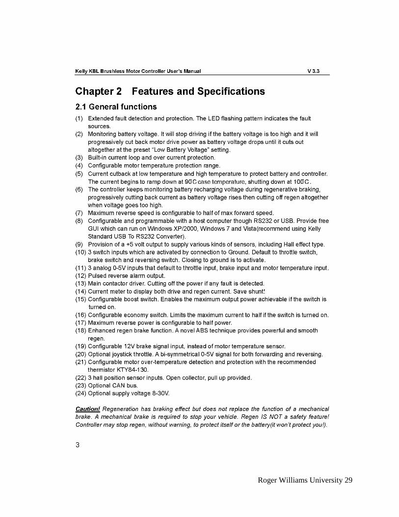
The onboard motor controller used was a Kelly KBL72401E controller was used to connect the
batteries and motor, provide a DC voltage boost, and handle inputs from the skipper. The
skipper will use a Curtis ET-126 throttle to control the rotations per minute of the motor shaft.
The Curtis throttle is powered my running a piece of 16-gauge wire from one of the D51R’s.
The input voltage of the throttle is 24 volts and outputs 0 to 5 volts that goes to charge controller
Roger Williams University 5
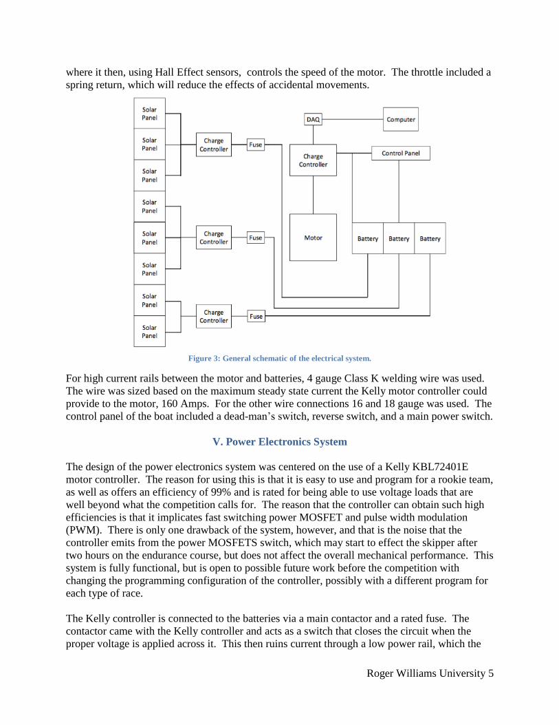
where it then, using Hall Effect sensors, controls the speed of the motor. The throttle included a
spring return, which will reduce the effects of accidental movements.
Figure 3: General schematic of the electrical system.
For high current rails between the motor and batteries, 4 gauge Class K welding wire was used.
The wire was sized based on the maximum steady state current the Kelly motor controller could
provide to the motor, 160 Amps. For the other wire connections 16 and 18 gauge was used. The
control panel of the boat included a dead-man’s switch, reverse switch, and a main power switch.
V. Power Electronics System
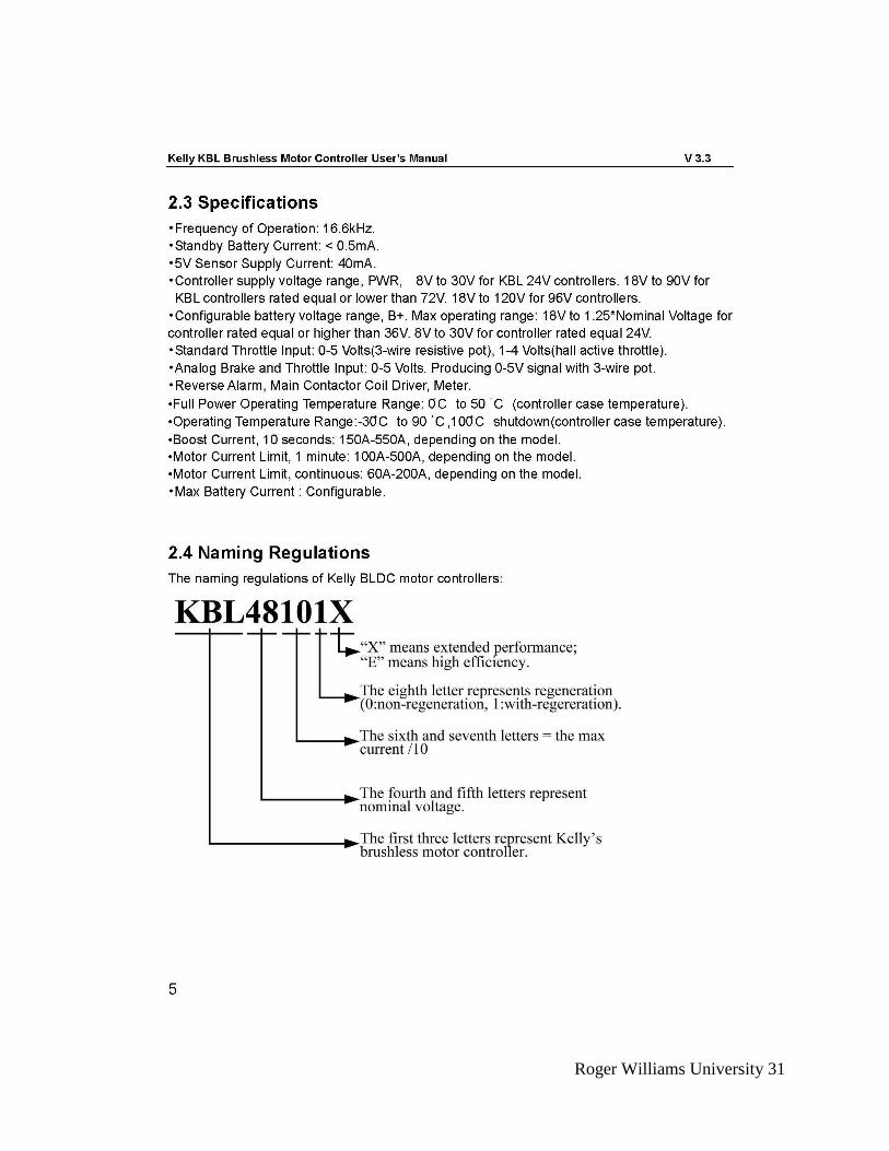
The design of the power electronics system was centered on the use of a Kelly KBL72401E
motor controller. The reason for using this is that it is easy to use and program for a rookie team,
as well as offers an efficiency of 99% and is rated for being able to use voltage loads that are
well beyond what the competition calls for. The reason that the controller can obtain such high
efficiencies is that it implicates fast switching power MOSFET and pulse width modulation
(PWM). There is only one drawback of the system, however, and that is the noise that the
controller emits from the power MOSFETS switch, which may start to effect the skipper after
two hours on the endurance course, but does not affect the overall mechanical performance. This
system is fully functional, but is open to possible future work before the competition with
changing the programming configuration of the controller, possibly with a different program for
each type of race.
The Kelly controller is connected to the batteries via a main contactor and a rated fuse. The
contactor came with the Kelly controller and acts as a switch that closes the circuit when the
proper voltage is applied across it. This then ruins current through a low power rail, which the
Roger Williams University 6
skipper can disconnect through two different means. First is a toggle switch, used as a main
power switch the switch must be flipped for the power to flow. The second possible disconnect
point is the dead-man’s-switch. A piece of this switch is attached to the skipper so that if they go
overboard the circuit is disconnected and the power stops. In order to shield the skipper form the
current of the circuit a rated diode is placed in parallel with the switches to draw any reverse
current away from the switches when the motor is slowed.
VI. Hull Design
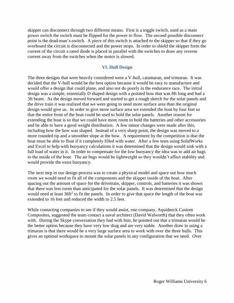
The three designs that were heavily considered were a V-hull, catamaran, and trimaran. It was
decided that the V-hull would be the best option because it would be easy to manufacture and
would offer a design that could plane, and also not do poorly in the endurance race. The initial
design was a simple, essentially D shaped design with a pointed bow that was 8ft long and had a
3ft beam. As the design moved forward and started to get a rough sketch for the solar panels and
the drive train it was realized that we were going to need more surface area than the original
design would give us. In order to give more surface area we extended the boat by four feet so
that the entire front of the boat could be used to hold the solar panels. Another reason for
extending the boat is so that we could have more room to hold the batteries and other accessories
and be able to have a good weight distribution. A few minor changes were made after this,
including how the bow was shaped. Instead of a very sharp point, the design was moved to a
more rounded tip and a smoother slope at the bow. A requirement by the competition is that the
boat must be able to float if it completely filled with water. After a few tests using SolidWorks
and Excel to help with buoyancy calculations it was determined that the design would sink with a
full load of water in it. In order to compensate for the low buoyancy the idea was to add air bags
to the inside of the boat. The air bags would be lightweight so they wouldn’t affect stability and
would provide the extra buoyancy.
The next step in our design process was to create a physical model and space out how much
room we would need to fit all of the components and the skipper inside of the boat. After
spacing out the amount of space for the drivetrain, skipper, controls, and batteries it was shown
that there was less room than anticipated for the solar panels. It was determined that the design
would need at least 36ft2 to fit the panels. In order to give that space the length of the boat was
extended to 16 feet and reduced the width to 2.5 feet.
While contacting companies to see if they would assist, one company, Aquidneck Custom
Composites, suggested the team contact a naval architect (David Walworth) that they often work
with. During the Skype conversation they had with him, he pointed out that a trimaran would be
the better option because they have very low drag and are very stable. Another draw to using a
trimaran is that there would be a very large surface area to work with over the three hulls. This
gives an optimal workspace to mount the solar panels in any configuration that we need. Over
Roger Williams University 7
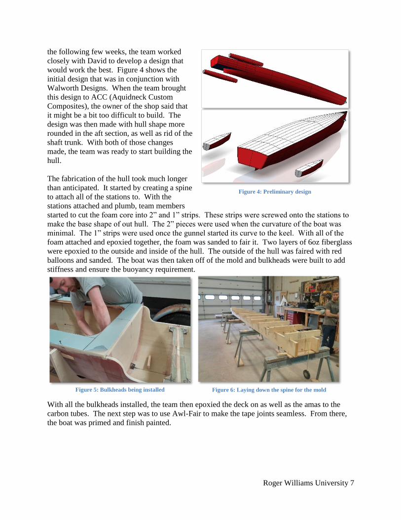
the following few weeks, the team worked
closely with David to develop a design that
would work the best. Figure 4 shows the
initial design that was in conjunction with
Walworth Designs. When the team brought
this design to ACC (Aquidneck Custom
Composites), the owner of the shop said that
it might be a bit too difficult to build. The
design was then made with hull shape more
rounded in the aft section, as well as rid of the
shaft trunk. With both of those changes
made, the team was ready to start building the
hull.
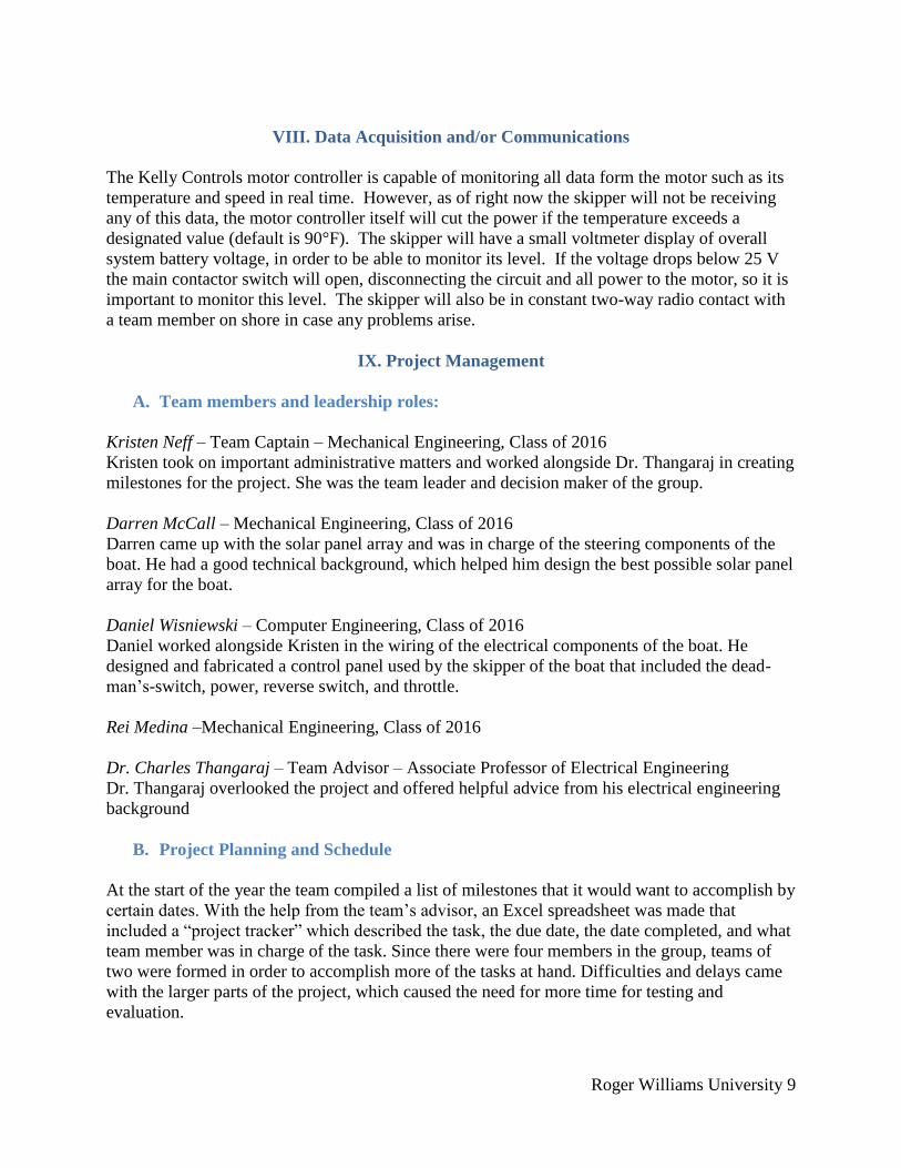
The fabrication of the hull took much longer
than anticipated. It started by creating a spine
to attach all of the stations to. With the
stations attached and plumb, team members
started to cut the foam core into 2” and 1” strips. These strips were screwed onto the stations to
make the base shape of out hull. The 2” pieces were used when the curvature of the boat was
minimal. The 1” strips were used once the gunnel started its curve to the keel. With all of the
foam attached and epoxied together, the foam was sanded to fair it. Two layers of 6oz fiberglass
were epoxied to the outside and inside of the hull. The outside of the hull was faired with red
balloons and sanded. The boat was then taken off of the mold and bulkheads were built to add
stiffness and ensure the buoyancy requirement.
With all the bulkheads installed, the team then epoxied the deck on as well as the amas to the
carbon tubes. The next step was to use Awl-Fair to make the tape joints seamless. From there,
the boat was primed and finish painted.
Figure 5: Bulkheads being installed Figure 6: Laying down the spine for the mold
Figure 4: Preliminary design

Roger Williams University 8
Once the assembly and painting were complete, the design of the electrical components and their
placement in the boat was able to move forward.
VII. Drive Train and Steering
The rudder for our boat is made from a composite material and was built by the International
Yacht Restoration School (IYRS) in Bristol, RI. The rudder consists of a solid 3/4th inch steel
shaft with metal flanges that are incased within the material for support. Additionally, the rudder
is primed and painted with the same paint used on the hull of the boat. To steer the rudder, we
experimented with a few different systems, but in the end, decided to electrically turn the rudder
as opposed to a manual pulley design. We mounted a Nextrox 12V 15RPM Electric DC Motor to
the shaft. The motor and rudder were connected with a heavy duty variable size flexible shaft
coupling from Mc Master-Carr, because the shaft of the motor and rudder were different sizes.
We designed a waterproof housing out of PVC pipe and machined ABS plastic to fit around the
shaft and motor. Finally, we wired the rudder motor up though the hull of the boat in front of the
skipper and connected it to a reversible polarity toggle switch to control the rudder movements.
Figure 7: Aligning the amas Figure 8: Attaching the foam core to the stations
Figure 9: Priming complete Figure 10: Priming the hull
Roger Williams University 9
VIII. Data Acquisition and/or Communications
The Kelly Controls motor controller is capable of monitoring all data form the motor such as its
temperature and speed in real time. However, as of right now the skipper will not be receiving
any of this data, the motor controller itself will cut the power if the temperature exceeds a
designated value (default is 90°F). The skipper will have a small voltmeter display of overall
system battery voltage, in order to be able to monitor its level. If the voltage drops below 25 V
the main contactor switch will open, disconnecting the circuit and all power to the motor, so it is
important to monitor this level. The skipper will also be in constant two-way radio contact with
a team member on shore in case any problems arise.
IX. Project Management
A. Team members and leadership roles:
Kristen Neff – Team Captain – Mechanical Engineering, Class of 2016
Kristen took on important administrative matters and worked alongside Dr. Thangaraj in creating
milestones for the project. She was the team leader and decision maker of the group.
Darren McCall – Mechanical Engineering, Class of 2016
Darren came up with the solar panel array and was in charge of the steering components of the
boat. He had a good technical background, which helped him design the best possible solar panel
array for the boat.
Daniel Wisniewski – Computer Engineering, Class of 2016
Daniel worked alongside Kristen in the wiring of the electrical components of the boat. He
designed and fabricated a control panel used by the skipper of the boat that included the dead-
man’s-switch, power, reverse switch, and throttle.
Rei Medina –Mechanical Engineering, Class of 2016
Dr. Charles Thangaraj – Team Advisor – Associate Professor of Electrical Engineering
Dr. Thangaraj overlooked the project and offered helpful advice from his electrical engineering
background
B. Project Planning and Schedule
At the start of the year the team compiled a list of milestones that it would want to accomplish by
certain dates. With the help from the team’s advisor, an Excel spreadsheet was made that
included a “project tracker” which described the task, the due date, the date completed, and what
team member was in charge of the task. Since there were four members in the group, teams of
two were formed in order to accomplish more of the tasks at hand. Difficulties and delays came
with the larger parts of the project, which caused the need for more time for testing and
evaluation.
Roger Williams University 10
C. Financial and Fundraising
Roger Williams University allocated a budget of $3,000, which allowed the team to get most of
the necessary materials that was needed for the boat. The team kept track of its spending in an
excel budget list spreadsheet.
The team sought potential fundraising from local boat yards. Two companies that helped the
team with most difficult problems were Jamestown Distributors and I.Y.R.S (International Yacht
Restoration School) both of Bristol, RI. There was also money allocated from one of Roger
Williams University’ chapters; the Provost Fund. An application was sent for a $1,500
contribution that dealt with looking for potential travel money. The Provost fund paid for the
team’s hotel in Dayton, Ohio as well as travel expenses.
D. Strategy for team continuity and sustainability
The team, along with its advisor, held weekly meetings varying in length of time depending on
what was to be accomplished. Team members had constant communication with one another
through text and email, along with attending the same classes. Team members would also meet
when able to work on the boat in pairs in order to build each of the systems of the boat.
E. Discussion and Self-Evaluation
The main challenge faced by this year’s team was the small team size, made smaller when one
team member, Rei Medina, dropped out, leaving only three members remaining. This required
the remaining members to focus their work much more upon their designated tasks, because
there was more weight on their shoulders. Throughout the year it was learned that the key to
successful team management was to divide each system into smaller tasks that could be
accomplished by only one or two people, which allowed each person to work individually on
their own time, rather than trying to force everyone’s schedules to coincide on a daily basis. By
setting goals and dividing up the work week by week even a team of three people was able to
build a competitive, functioning boat. In future years other teams can build off of our work and
make the boat more efficient, especially the weight of the boat and its components, such as the
solar panels.
X. Conclusions and Recommendations
For future Roger Williams’ teams there are a few recommendations that could be made to
change the design of the boat. First of all, the steering is not self-centering; the skipper does
have to steer back to center. Also, several teams have a multiple-motor system for the Sprint
Course, so future teams may look into that.
Due to the fact that we are the first team to go to competition, we are not yet entirely sure of how
our boat will measure in competition. Once we compete in June we will have a better idea of
what advice to leave behind.

Roger Williams University 11
XI. References
[1] Renogy 30amp PWM Charge controllers http://www.amazon.com/Renogy-Wanderer-30A-Charge-Controller/dp/B00BCTLIHC [2] Podoy GMA 10amp Fuse http://www.amazon.com/PODOY-Qty-Fast-Blow-GMA10A-GMA10/dp/B004HLYUE0 [3] 4 gauge Red and Black Audio Cable http://www.amazon.com/Gauge-BLACK-Audio-Power-Ground/dp/B00L9CB6WE [4] Islandoffer MC4 Cable Connectors http://www.amazon.com/Islandoffer-Pairs-Female-Solar-Connectors/dp/B00A8TRKJW [5] Installgear Battery terminal Clamps http://www.amazon.com/InstallGear-Positive-Negative-Battery- Terminal/dp/B00NQ7U982/ref=sr_1_3?s=automotive&ie=UTF8&qid=1462821681&sr=1-3&keywords=Battery+terminal+Clamps [6] Mighty Max 12v Deep Cycle Batteries http://www.amazon.com/ML35-12-STORAGE-BATTERY-Battery-product/dp/B00K8E4LR6/ref=sr_1_6_s_it?s=hpc&ie=UTF8&qid=1462821713&sr=1-6&keywords=Mighty+Max+12v+Deep+Cycle+Batterys [7] Aleko 60Watt Monocrystalline Solar Panel http://www.amazon.com/ALEKO%C2%AE-60W-60-Watt-Monocrystalline-Solar/dp/B007YT9222 [8] Aluminum L Bracket http://www.homedepot.com/p/Everbilt-96-in-x-1-in-Aluminum-Flat-Angle-with-x-1-8-in-Thick-802517/204273955 [9] Nextrox mini gear box motor http://www.amazon.com/dp/B00B1KXV3Q/ref=twister_B00Y7Z2SA4?_encoding=UTF8&psc=1 [10] IMC audio AUG inline fuse holder http://www.amazon.com/Holder-Fuseholder-IMC-Audio-Inline/dp/B015AJQIWO/ref=sr_1_fkmr1_1?s=hi&ie=UTF8&qid=1462821846&sr=1-1-fkmr1&keywords=IMC+audio+AUG+inline+fuse+holder [11] 8 gauge Wire http://www.homedepot.com/p/Southwire-By-the-Foot-6-Black-Stranded-CU-THHN-Wire-20493399/204632784 [12] PVC Pipe http://www.homedepot.com/p/VPC-3-in-x-2-ft-PVC-Sch-40-Pipe-2203/205706641 [13] Wind Shield http://www.ebay.com/sch/i.html?_odkw=windshield&_osacat=0&ssPageName=GSTL&_from=R40&_trksid=p2045573.m570.l1313.TR0.TRC0.H0.Xwindshield++moped.TRS0&_nkw=windshield++moped&_sacat=0 [14] Shaft Coupling http://www.mcmaster.com/#standard-shaft-couplings/=12c7j95 [15] Switch http://www.acehardware.com/product/index.jsp?productId=83872176 [16] Switch http://www.acehardware.com/product/index.jsp?productId=83872156 [17] Switch

Roger Williams University 12
http://www.amazon.com/Sea-Dog-420488-1-Switch-Lanyard/dp/B00DH3QHBI/ref=sr_1_1?s=boating-water-sports&ie=UTF8&qid=1462822325&sr=1-1&keywords=kill+switch [18] Switch http://www.amazon.com/HOTSYSTEM-Aircraft-Carbon-Automotive-Illuminated/dp/B0061GQUS8/ref=sr_1_13?ie=UTF8&qid=1462822378&sr=8-13&keywords=on+off+switch [19] Paint http://www.jamestowndistributors.com/userportal/show_product.do?pid=1438 [20] Paint rollers http://www.acehardware.com/product/index.jsp?productId=34220626 [21] Sand paper http://www.acehardware.com/search/index.jsp?kwCatId=&kw=sandpaper&origkw=sand+paper&f=Taxonomy/ACE/19541496&sr=1 [22] Nuts, Bolts, Screws http://www.homedepot.com/s/bolts?NCNI-5 [23] ABS Plastic http://www.mcmaster.com/#abs-plastic/=12c7jhm
Roger Williams University 13
XII. Appendices
Appendix A: Battery Documentation
Roger Williams University 14

Roger Williams University 15
Roger Williams University 16
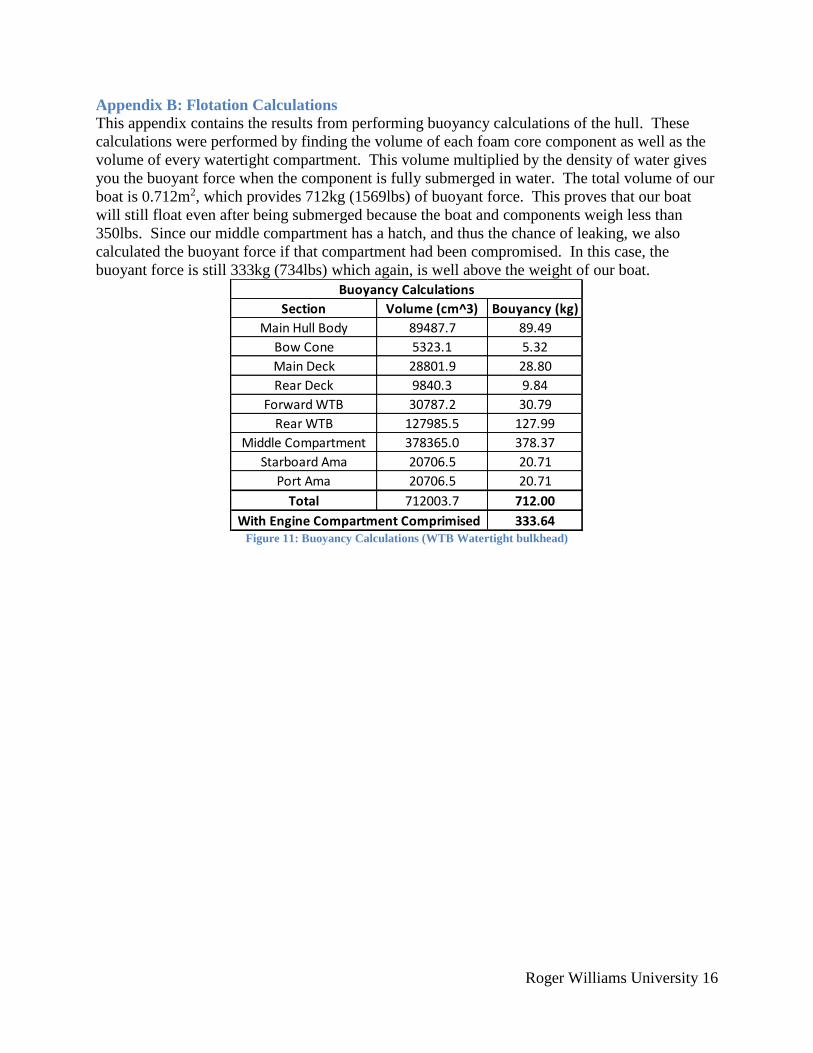
Appendix B: Flotation Calculations
This appendix contains the results from performing buoyancy calculations of the hull. These
calculations were performed by finding the volume of each foam core component as well as the
volume of every watertight compartment. This volume multiplied by the density of water gives
you the buoyant force when the component is fully submerged in water. The total volume of our
boat is 0.712m2, which provides 712kg (1569lbs) of buoyant force. This proves that our boat
will still float even after being submerged because the boat and components weigh less than
350lbs. Since our middle compartment has a hatch, and thus the chance of leaking, we also
calculated the buoyant force if that compartment had been compromised. In this case, the
buoyant force is still 333kg (734lbs) which again, is well above the weight of our boat.
Figure 11: Buoyancy Calculations (WTB Watertight bulkhead)
Section Volume (cm^3) Bouyancy (kg)
Main Hull Body 89487.7 89.49
Bow Cone 5323.1 5.32
Main Deck 28801.9 28.80
Rear Deck 9840.3 9.84
Forward WTB 30787.2 30.79
Rear WTB 127985.5 127.99
Middle Compartment 378365.0 378.37
Starboard Ama 20706.5 20.71
Port Ama 20706.5 20.71
Total 712003.7 712.00
333.64
Buoyancy Calculations
With Engine Compartment Comprimised
Roger Williams University 17
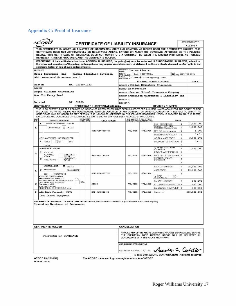
Appendix C: Proof of Insurance
Roger Williams University 18
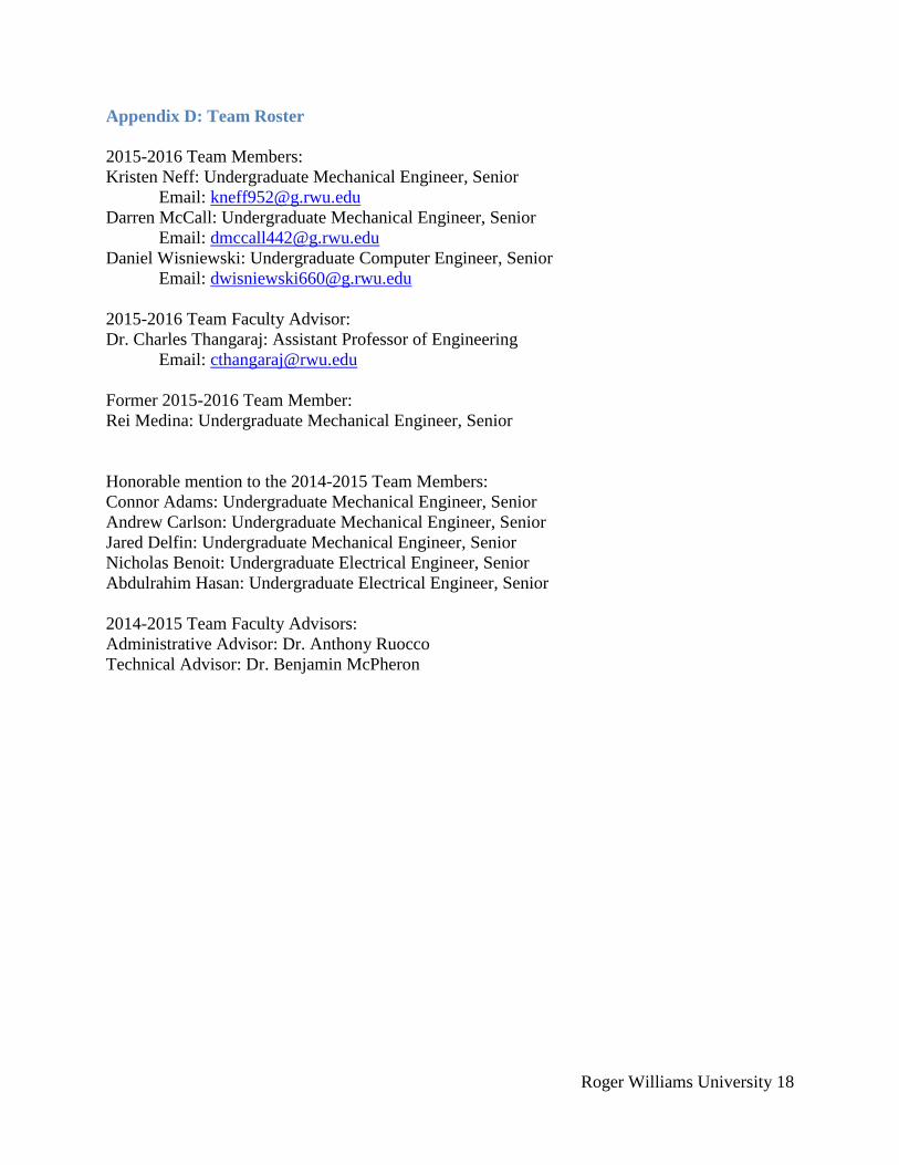
Appendix D: Team Roster
2015-2016 Team Members:
Kristen Neff: Undergraduate Mechanical Engineer, Senior
Email: [email protected]
Darren McCall: Undergraduate Mechanical Engineer, Senior
Email: [email protected]
Daniel Wisniewski: Undergraduate Computer Engineer, Senior
Email: [email protected]
2015-2016 Team Faculty Advisor:
Dr. Charles Thangaraj: Assistant Professor of Engineering
Email: [email protected]
Former 2015-2016 Team Member:
Rei Medina: Undergraduate Mechanical Engineer, Senior
Honorable mention to the 2014-2015 Team Members:
Connor Adams: Undergraduate Mechanical Engineer, Senior
Andrew Carlson: Undergraduate Mechanical Engineer, Senior
Jared Delfin: Undergraduate Mechanical Engineer, Senior
Nicholas Benoit: Undergraduate Electrical Engineer, Senior
Abdulrahim Hasan: Undergraduate Electrical Engineer, Senior
2014-2015 Team Faculty Advisors:
Administrative Advisor: Dr. Anthony Ruocco
Technical Advisor: Dr. Benjamin McPheron
Roger Williams University 19
Appendix E: The G-code used to create the steering mechanism
G-code for the base mount of steering assembly
(propeller-base-mount-Groove)
N000 G20 M09
N010 G90
N020 M48
N030 F2 S1000 M04
N035 G01 Z.1
N040 G01 Z-0.375
N050 G01 X0.0 Y0.0
N060 G01 X1.25 Y0.0
N070 G02 X1.25 Y0.0 I-1.25 J0.0
N040 G01 Z-0.75
N070 G02 X1.25 Y0.0 I-1.25 J0.0
N080 F10
N090 G01 x0.0 Y0.0 Z0.1
N100 G01 X1.67
N105 F2
N110 G01 Z-0.375
N120 G01 X1.67 Y0.0
N130 G02 X1.67 Y0.0 I-1.67 J0.0
N140 G01 X1.590 Y0.0
N150 G02 X1.590 Y0.0 I-1.590 J0.0
N160 F10
N170 G01 Z.1
N180 G01 x0.0 Y0.0 Z0.1
N190 M2
G-code for the motor mount of steering assembly
(propeller-motor-mount-Groove)
N000 G20 M09
N010 G90
N020 M48
N030 F2 S1000 M04
N035 G01 Z.1
NO40 G01 Z-.7
N050 G01 X0.0 Y.2953
N060 G01 X.545 Y0.0
N070 G02 X.545 Y0.0 I-.545 J0.0
N075 F10
N080 G01 Z.1
N090 G01 X0.0 Y0.0 Z0.1
N100 G01 X1.590 Y0.0
N105 F2
N110 G01 z-.7
N120 G02 X1.590 Y0.0 I-1.590 J0.0
N130 F10

Roger Williams University 20
N140 G01 Z.1
N150 G01 x0.0 Y0.0 Z0.1
N160 M2
Roger Williams University 21
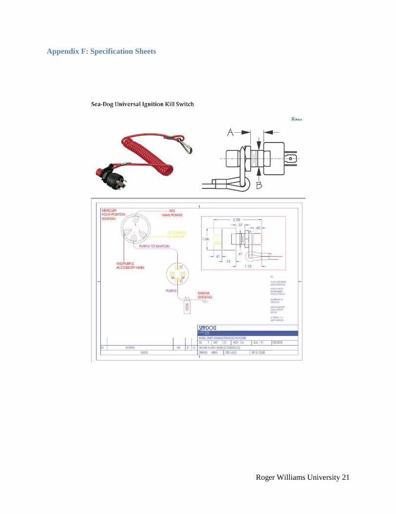
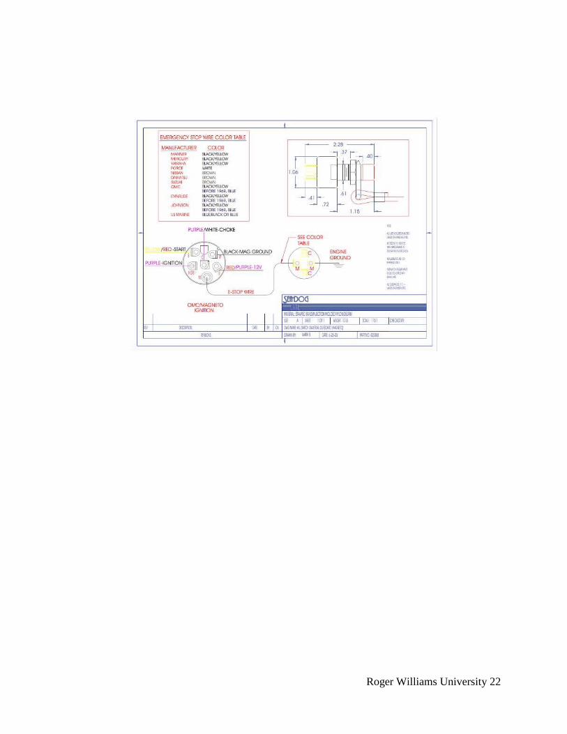
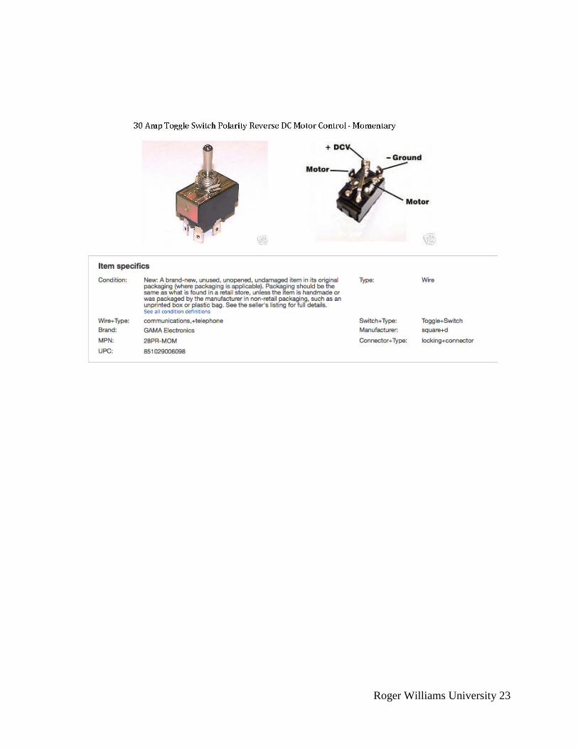
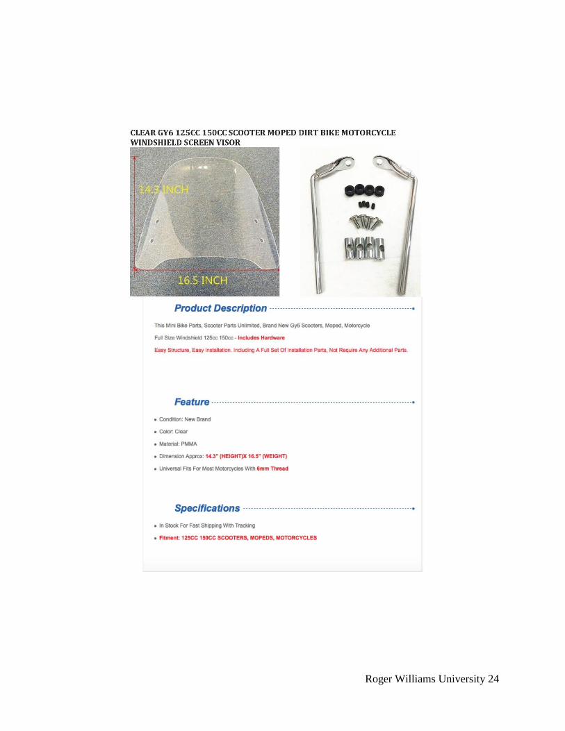
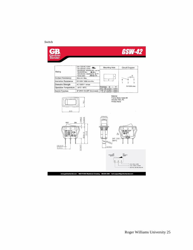
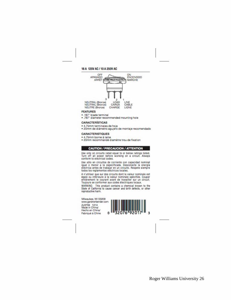
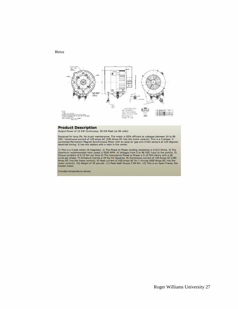
Appendix F: Specification Sheets
Roger Williams University 22
Roger Williams University 23
Roger Williams University 24
Roger Williams University 25
Roger Williams University 26
Roger Williams University 27
Roger Williams University 28
Roger Williams University 29
Roger Williams University 30
Roger Williams University 31
Roger Williams University 32

Roger Williams University 33
Appendix G: Driveshaft Calculations