Embed Size (px)
Citation preview

WESTCAST, INC. 260 NORTH ELM STREET 7555 TRANMERE DRIVE WESTFIELD, MA 01085 MISSISSAUGA,ONTARIO L5S 1L4 TEL. (413) 562-9631 FAX (413) 562-3799 TEL. (905) 672-2991 FAX (905) 672-2883
8-IOM-11R
8 SERIESSTEAM OR HOT WATER BOILER-BURNER UNIT
INSTALLATION & OPERATING INSTRUCTIONS
DESIGNED AND TESTED ACCORDING TO A.S.M.E. BOILER AND PRESSURE VESSEL CODE, SECTION IV FOR A MAXIMUM ALLOWABLE WORKING PRESSURE OF: 15 PSI STEAM OR 40 PSI WATER.
CONSUMER, RETAIN THESE INSTRUCTIONS FOR FUTURE REFERENCE PURPOSES.
*WATER BOILERS ONLY.
TO INSTALLERNOTE: READ THESE INSTRUCTIONS CAREFULLY. THEY WILL SAVE YOU VALUABLE TIME WHEN ASSEMBLING THE BOILER.
CAUTION: Do not use automotive anti-freeze in boiler waterways. If necessary to use anti-freeze, be sure to employ a preparation designed for hydronic heating systems such as ethylene or propylene glycol.
THESE INSTRUCTIONS TO BE LEFT WITH THE BOILER FOR REFERENCE PURPOSES.
01/13
ENERGY STARENERGY STAR
*
8 SERIES BOILER INSTALLATION AND OPERATING INSTRUCTIONSPage 2
CONTENTSGeneral .......................................................................2Codes, Rules and Regulations ...................................2Boiler Location ............................................................2Chimney and Breeching .............................................3Combustion and Ventilation ........................................3Inspection ...................................................................4Boiler Blocks ...............................................................4Jacket Assembly .........................................................4Cleanout Cover Plates ................................................4Boiler Trim .........................................(Water) 5, (Steam) 11Thermostat and Limit Controls ..........(Water) 5, (Steam) 12Piping Connections ............................(Water) 6, (Steam) 11Circulators ..................................................................8Domestic Hot Water Heaters ......................................9Filling the System ..............................(Water) 8, (Steam) 14Boiler Maintenance .......................(Water) 9-10, (Steam) 15Steam Boiler Cable Installation ................................16Replacement Parts ...................................................19Start-Up Checklist ....................................................21Burner Specifi cations ...............................................22Warranty ...................................................................25
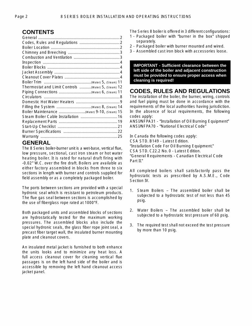
GENERALThe 8 Series boiler-burner unit is a wet-base, vertical fl ue, low pressure, sectional, cast iron steam or hot water heating boiler. It is rated for natural draft firing with -0.02" W.C. over the fi re draft. Boilers are available as either factory assembled in blocks from three to six sections in length with burner and controls supplied for fi eld assembly or as a completely packaged boiler.
The ports between sections are provided with a special hydronic seal which is resistant to petroleum products. The fl ue gas seal between sections is accomplished by the use of fi berglass rope rated at 1000°F.
Both packaged units and assembled blocks of sections are hydrostatically tested for the maximum working pressures. The assembled blocks also include the special hydronic seals, the glass fi ber rope joint seal, a precast fi ber target wall, the insulated burner mounting plate and cleanout covers.
An insulated metal jacket is furnished to both enhance the units looks and to minimize any heat loss. A full access cleanout cover for cleaning vertical fl ue passages is on the left hand side of the boiler and is accessible by removing the left hand cleanout access jacket panel.
The Series 8 boiler is offered in 3 different confi gurations:1 - Packaged boiler with “burner in the box” shipped
separately.2 - Packaged boiler with burner mounted and wired.3 - Assembled cast iron block with accessories loose.
IMPORTANT - Suffi cient clearance between the left side of the boiler and adjacent construction must be provided to ensure proper access when cleaning is required!
CODES, RULES AND REGULATIONSThe installation of the boiler, the burner, wiring, controls and fuel piping must be done in accordance with the requirements of the local authorities having jurisdiction. In the absence of local requirements, the following codes apply:ANSI/NFPA31 - “Installation of Oil Burning Equipment”ANSI/NFPA70 - “National Electrical Code”
In Canada the following codes apply:CSA STD. B149 - Latest Edition. “Installation Code For Oil Burning Equipment.”CSA STD. C22.2 No. 0 - Latest Edition. “General Requirements - Canadian Electrical Code Part II.”
All completed boilers shall satisfactorily pass the hydrostatic tests as prescribed by A.S.M.E., Code Section IV.
1. Steam Boilers – The assembled boiler shall be subjected to a hydrostatic test of not less than 45 psig.
2. Water Boilers – The assembled boiler shall be subjected to a hydrostatic test pressure of 60 psig.
3. The required test shall not exceed the test pressure by more than 10 psig.
8 SERIES BOILER INSTALLATION AND OPERATING INSTRUCTIONS Page 3
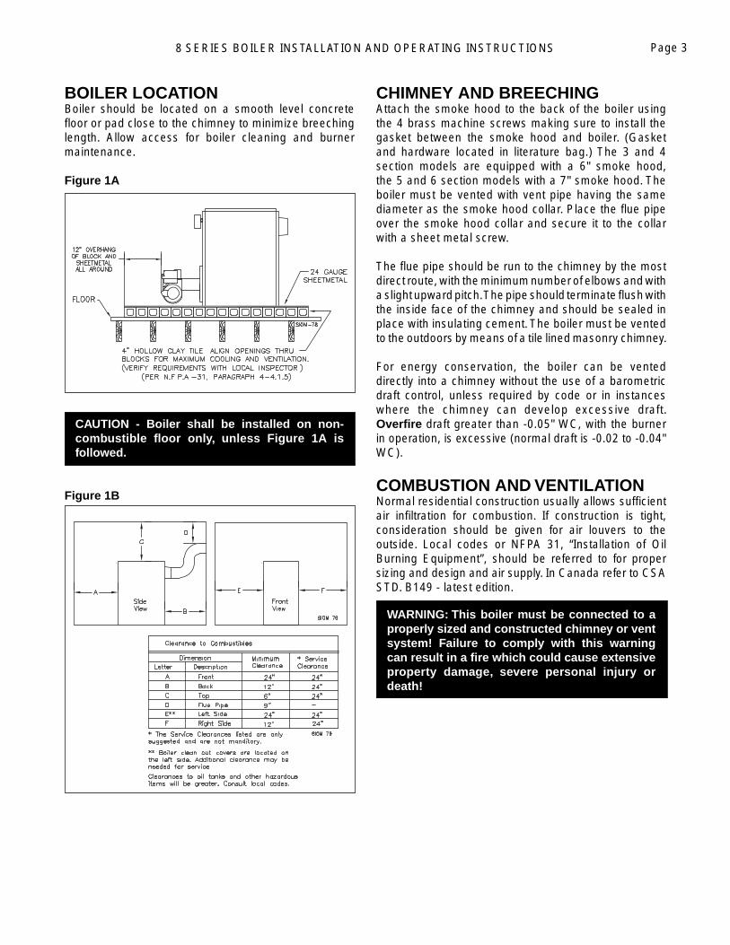
BOILER LOCATIONBoiler should be located on a smooth level concrete fl oor or pad close to the chimney to minimize breeching length. Allow access for boiler cleaning and burner maintenance.
Figure 1A
CAUTION - Boiler shall be installed on non-combustible fl oor only, unless Figure 1A is followed.
Figure 1B
CHIMNEY AND BREECHINGAttach the smoke hood to the back of the boiler using the 4 brass machine screws making sure to install the gasket between the smoke hood and boiler. (Gasket and hardware located in literature bag.) The 3 and 4 section models are equipped with a 6" smoke hood, the 5 and 6 section models with a 7" smoke hood. The boiler must be vented with vent pipe having the same diameter as the smoke hood collar. Place the fl ue pipe over the smoke hood collar and secure it to the collar with a sheet metal screw.
The fl ue pipe should be run to the chimney by the most direct route, with the minimum number of elbows and with a slight upward pitch. The pipe should terminate fl ush with the inside face of the chimney and should be sealed in place with insulating cement. The boiler must be vented to the outdoors by means of a tile lined masonry chimney.
For energy conservation, the boiler can be vented directly into a chimney without the use of a barometric draft control, unless required by code or in instances where the chimney can develop excessive draft. Overfi re draft greater than -0.05" WC, with the burner in operation, is excessive (normal draft is -0.02 to -0.04" WC).
COMBUSTION AND VENTILATIONNormal residential construction usually allows suffi cient air infi ltration for combustion. If construction is tight, consideration should be given for air louvers to the outside. Local codes or NFPA 31, “Installation of Oil Burning Equipment”, should be referred to for proper sizing and design and air supply. In Canada refer to CSA STD. B149 - latest edition.
WARNING: This boiler must be connected to a properly sized and constructed chimney or vent system! Failure to comply with this warning can result in a fi re which could cause extensive property damage, severe personal injury or death!
8 SERIES BOILER INSTALLATION AND OPERATING INSTRUCTIONSPage 4
INSPECTIONCareful inspection should be made of all assemblies to detect possible damage during shipment. Factory assembled boilers are hydrostatically tested at the factory to insure pressure tightness. Before piping connections are made to the boiler, hydrostatically retest boiler sections to detect leaks that may have developed from rough handling during shipment. (Maximum allowable working pressure of 15 psi steam or 80 psi water)
The “Burner in the Box”Packaged boilers with “The Burner in the Box” are shipped on a wood skid with tie down bands and a wooden crate enclosing the boiler. The boiler is shipped without the burner being mounted and wired in place. The burner is shipped and inventoried independently of the boiler. Burners from Carlin, Beckett and Riello are available as options. The 8-Series boiler is equipped with a universal harness system utilizing a 6-pin electrical connector. The harness system has been designed to allow any of these burners to connect to both steam and water boilers. The harness system is designed to make burner replacement and routine servicing quicker and safer to perform.
PACKAGED BOILERSPackaged boilers are shipped on a wood skid with tie down bands and a wooden crate enclosing the boiler and burner installed.
Remove the protective crate and skid. Set the boiler in its fi nal location and shim under the feet to make it level and secure. Adjust the jacket for proper alignment and support. Refer to Oil Fired Boiler Electrical Diagrams (8EWD) for appropriate wiring diagrams.
BOILER BLOCKSBlocks are arranged for use either as steam or water boilers. All steam boilers have a fl anged opening in the back section on the left side, below the water line. A tankless heater may be installed in this location. Water boilers utilize the opening in the front section for a tankless coil.
Unlike the packaged units, assembled blocks require a smokehood, controls, burner, steam or water trim, LWCO, circulators (water boilers), and jackets must be installed in the fi eld.
CLEANOUT COVER PLATE(S)It is important to maintain the integrity of the gas seal by careful installation of the cleanout cover plate. Be sure there is no opening to allow gases to escape.
WARNING: Never attempt to operate the boiler with the cleanout cover plates removed! Failure to comply with this warning can result in a fi re which could cause extensive property damage, severe personal injury or death!
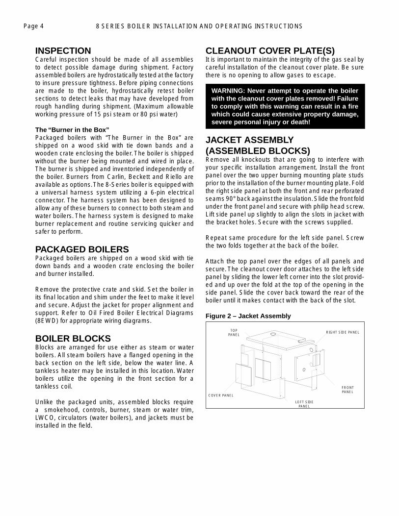
JACKET ASSEMBLY (ASSEMBLED BLOCKS)Remove all knockouts that are going to interfere with your specifi c installation arrangement. Install the front panel over the two upper burning mounting plate studs prior to the installation of the burner mounting plate. Fold the right side panel at both the front and rear perforated seams 90° back against the insulation. Slide the front fold under the front panel and secure with philip head screw. Lift side panel up slightly to align the slots in jacket with the bracket holes. Secure with the screws supplied.
Repeat same procedure for the left side panel. Screw the two folds together at the back of the boiler.
Attach the top panel over the edges of all panels and secure. The cleanout cover door attaches to the left side panel by sliding the lower left corner into the slot provid-ed and up over the fold at the top of the opening in the side panel. Slide the cover back toward the rear of the boiler until it makes contact with the back of the slot.
Figure 2 – Jacket Assembly
FRONT PANEL
LEFT SIDE PANEL
RIGHT SIDE PANELTOP PANEL
COVER PANEL
8 SERIES BOILER INSTALLATION AND OPERATING INSTRUCTIONS Page 5
WATER BOILERS
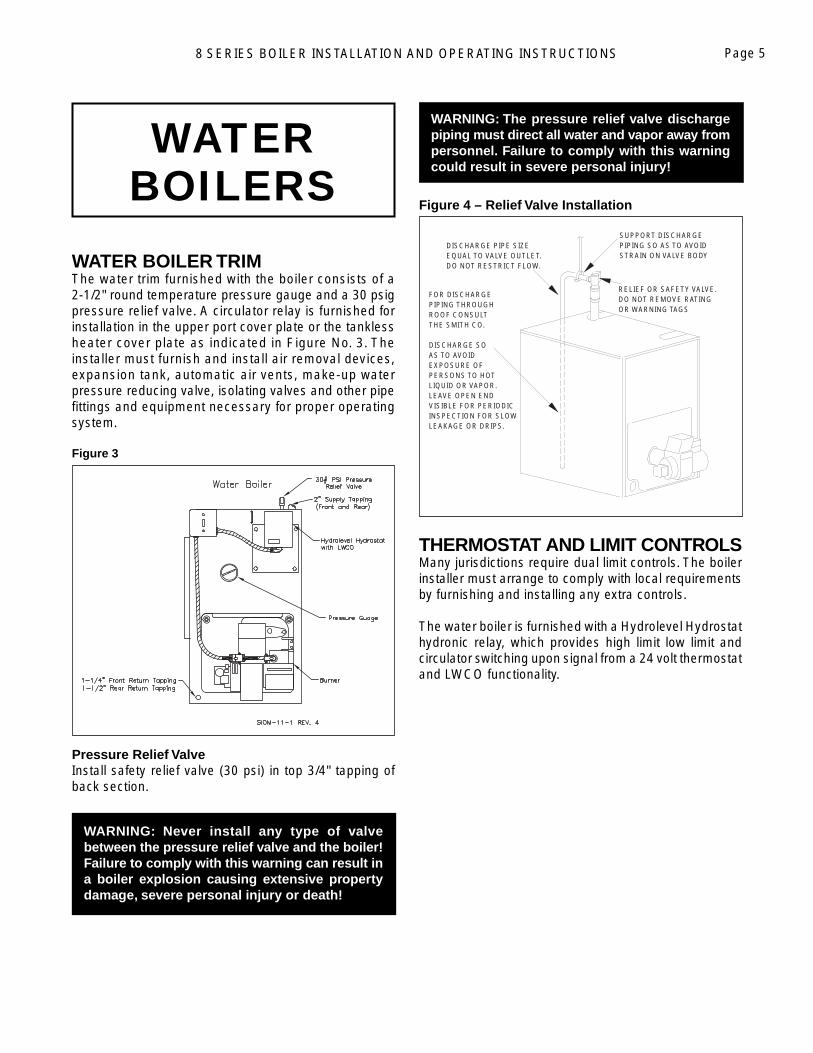
WATER BOILER TRIM The water trim furnished with the boiler consists of a 2-1/2" round temperature pressure gauge and a 30 psig pressure relief valve. A circulator relay is furnished for installation in the upper port cover plate or the tankless heater cover plate as indicated in Figure No. 3. The installer must furnish and install air removal devices, expansion tank, automatic air vents, make-up water pressure reducing valve, isolating valves and other pipe fi ttings and equipment necessary for proper operating system.
Figure 3
Pressure Relief ValveInstall safety relief valve (30 psi) in top 3/4" tapping of back section.
WARNING: Never install any type of valve between the pressure relief valve and the boiler! Failure to comply with this warning can result in a boiler explosion causing extensive property damage, severe personal injury or death!
WARNING: The pressure relief valve discharge piping must direct all water and vapor away from personnel. Failure to comply with this warning could result in severe personal injury!
Figure 4 – Relief Valve Installation
THERMOSTAT AND LIMIT CONTROLSMany jurisdictions require dual limit controls. The boiler installer must arrange to comply with local requirements by furnishing and installing any extra controls.
The water boiler is furnished with a Hydrolevel Hydrostat hydronic relay, which provides high limit low limit and circulator switching upon signal from a 24 volt thermostat and LWCO functionality.
SUPPORT DISCHARGEPIPING SO AS TO AVOIDSTRAIN ON VALVE BODY
FOR DISCHARGEPIPING THROUGHROOF CONSULTTHE SMITH CO.
DISCHARGE SOAS TO AVOIDEXPOSURE OFPERSONS TO HOTLIQUID OR VAPOR.LEAVE OPEN ENDVISIBLE FOR PERIODICINSPECTION FOR SLOWLEAKAGE OR DRIPS.
RELIEF OR SAFETY VALVE.DO NOT REMOVE RATINGOR WARNING TAGS
DISCHARGE PIPE SIZEEQUAL TO VALVE OUTLET.DO NOT RESTRICT FLOW.
8 SERIES BOILER INSTALLATION AND OPERATING INSTRUCTIONSPage 6
A qua s tat T he r mo m ete r R e d u c i n g V a l ve
P re s s ur e P um p B a l a n c e V a l ve B ac k f l o w - P re v en t i on De v i ce
E xp a nsion Tan k
P re s s ur e Rel i e f V a l ve
Che c k V a l ve
N O T ES :
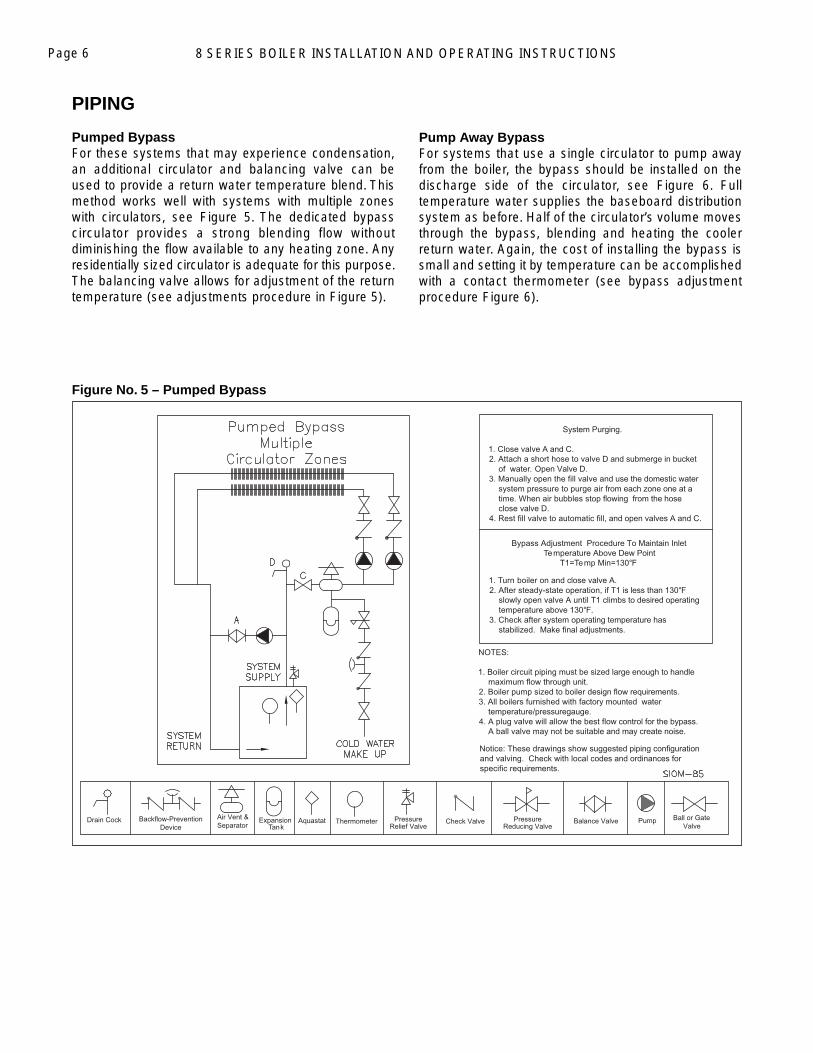
1 . B o il e r c ir cu it p i p i ng m us t be s i z ed large enough to handle m ax i m u m fl o w through unit . 2. Boiler pump sized to boiler d es i gn fl o w r equirements . 3. All boilers furnished with f ac t ory m ounted water t e m pe r a t u r e / pressuregauge . 4. A plug valve will allow the best fl o w control for the bypass . A ba ll va l ve m ay no t be su it a ble and may create noise .
Notice: These drawings show sugge s t ed p i p i ng c onfiguratio n and valving. Check with local c odes and ordinances for specific req u i r e m en t s .
1. Turn boiler on and c l ose valve A . 2. After steady-state operation, if T 1 i s l ess than 130° F slowly open valve A until T1 cl i m bs t o desired operatin g t e m pe r a t u r e above 130° F.3. Check after system opera t i ng t e m pe r a t u r e ha s s tabilized. Make fi na l ad j us t m en t s .
Bypass Adjustment Procedu r e T o M a i n t a i n I n l e t Te m pe r a t u r e A b ove Dew Point
T1 = Te m p M i n = 130° F
Drain Cock B a l l o r G a te V a lv e
S ys t e m P u r g i ng .
1. Close valv e A and C . 2. Attach a short hose to valve D and submerge in bucke t o f w a ter. O p en V a l ve D . 3. Manually open the fill valve a nd use the domestic wate r system pressure to purge air fr o m each zone one at a time. W hen air bubbles stop fl o w i ng fr o m t he hos e close va l ve D . 4 . R es t fill va l ve t o au t o m a ti c fill, and open v al v e s A and C .
A i r V e n t & S epa r ato r
Figure No. 5 – Pumped Bypass
PIPING
Pumped BypassFor these systems that may experience condensation, an additional circulator and balancing valve can be used to provide a return water temperature blend. This method works well with systems with multiple zones with circulators, see Figure 5. The dedicated bypass circulator provides a strong blending flow without diminishing the fl ow available to any heating zone. Any residentially sized circulator is adequate for this purpose. The balancing valve allows for adjustment of the return temperature (see adjustments procedure in Figure 5).
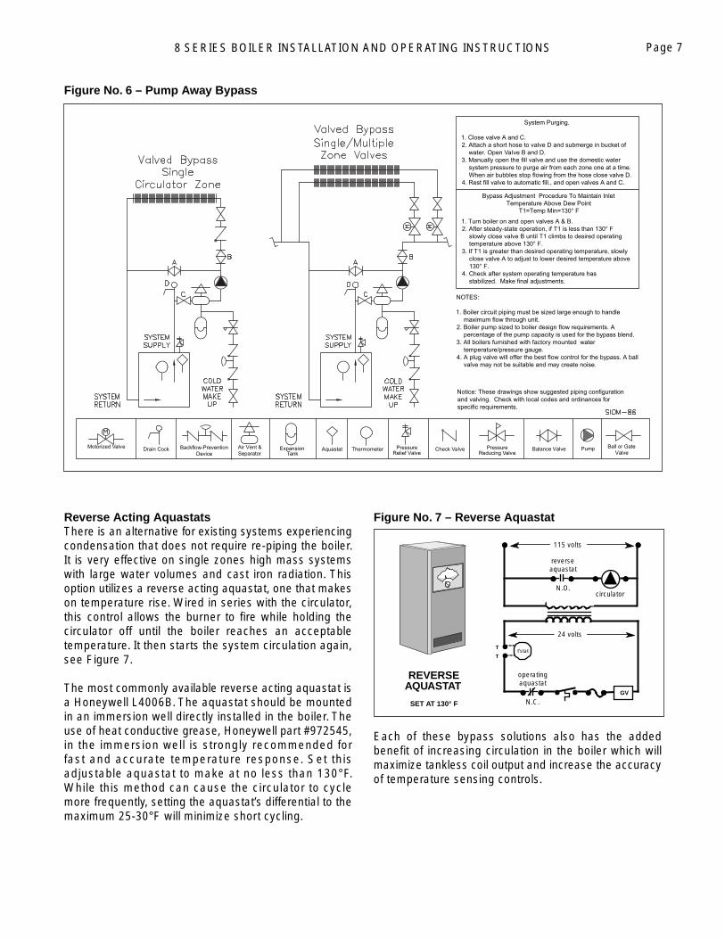
Pump Away BypassFor systems that use a single circulator to pump away from the boiler, the bypass should be installed on the discharge side of the circulator, see Figure 6. Full temperature water supplies the baseboard distribution system as before. Half of the circulator’s volume moves through the bypass, blending and heating the cooler return water. Again, the cost of installing the bypass is small and setting it by temperature can be accomplished with a contact thermometer (see bypass adjustment procedure Figure 6).
8 SERIES BOILER INSTALLATION AND OPERATING INSTRUCTIONS Page 7
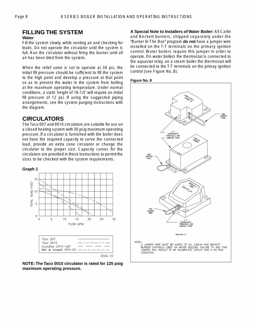
Reverse Acting AquastatsThere is an alternative for existing systems experiencing condensation that does not require re-piping the boiler. It is very effective on single zones high mass systems with large water volumes and cast iron radiation. This option utilizes a reverse acting aquastat, one that makes on temperature rise. Wired in series with the circulator, this control allows the burner to fi re while holding the circulator off until the boiler reaches an acceptable temperature. It then starts the system circulation again, see Figure 7.
The most commonly available reverse acting aquastat is a Honeywell L4006B. The aquastat should be mounted in an immersion well directly installed in the boiler. The use of heat conductive grease, Honeywell part #972545, in the immersion well is strongly recommended for fast and accurate temperature response. Set this adjustable aquastat to make at no less than 130°F. While this method can cause the circulator to cycle more frequently, setting the aquastat’s differential to the maximum 25-30°F will minimize short cycling.
Figure No. 7 – Reverse Aquastat
Each of these bypass solutions also has the added benefi t of increasing circulation in the boiler which will maximize tankless coil output and increase the accuracy of temperature sensing controls.
reverseaquastat
N.O.
T
Tt'stat
GV
115 volts
24 volts
circulator
operatingaquastat
N.C.
REVERSEAQUASTAT
SET AT 130° F
Figure No. 6 – Pump Away Bypass
Aquastat ThermometerReducing Valve
Pressure PumpBalance Valve
1. Turn boiler on and open valves A & B.2. After steady-state operation, if T1 is less than 130° F slowly close valve B until T1 climbs to desired operating temperature above 130° F.3. If T1 is greater than desired operating temperature, slowly close valve A to adjust to lower desired temperature above 130° F.4. Check after system operating temperature has stabilized. Make final adjustments.
Bypass Adjustment Procedure To Maintain Inlet Temperature Above Dew Point
T1=Temp Min=130° F
Backflow-Prevention Device
Expansion Tank
PressureRelief Valve
Check Valve
NOTES:
1. Boiler circuit piping must be sized large enough to handle maximum flow through unit.2. Boiler pump sized to boiler design flow requirements. A percentage of the pump capacity is used for the bypass blend. 3. All boilers furnished with factory mounted water temperature/pressure gauge.4. A plug valve will offer the best flow control for the bypass. A ball valve may not be suitable and may create noise.
Notice: These drawings show suggested piping configuration and valving. Check with local codes and ordinances for specific requirements.
Motorized Valve Drain Cock Ball or Gate Valve
Air Vent & Separator
System Purging.
1. Close valve A and C.2. Attach a short hose to valve D and submerge in bucket of water. Open Valve B and D. 3. Manually open the fill valve and use the domestic water system pressure to purge air from each zone one at a time. When air bubbles stop flowing from the hose close valve D.4. Rest fill valve to automatic fill., and open valves A and C.
8 SERIES BOILER INSTALLATION AND OPERATING INSTRUCTIONSPage 8
FILLING THE SYSTEM WaterFill the system slowly, while venting air and checking for leaks. Do not operate the circulator until the system is full. Run the circulator without fi ring the burner until all air has been bled from the system.
When the relief valve is set to operate at 30 psi, the initial fi ll pressure should be suffi cient to fi ll the system to the high point and develop a pressure at that point so as to prevent the water in the system from boiling at the maximum operating temperature. Under normal conditions, a static height of 18-1/2' will require an initial fi ll pressure of 12 psi. If using the suggested piping arrangements, see the system purging instructions with the diagram.
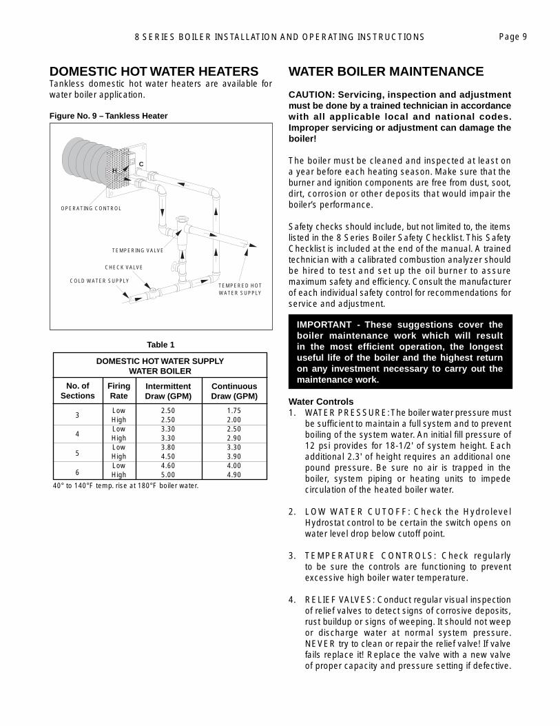
CIRCULATORSThe Taco 007 and 0010 circulators are suitable for use on a closed heating system with 30 psig maximum operating pressure. If a circulator is furnished with the boiler does not have the required capacity to serve the connected load, provide an extra zone circulator or change the circulator to the proper size. Capacity curves for the circulators are provided in these instructions to permit the sizes to be checked with the system requirements.
Graph 1
NOTE: The Taco 0010 circulator is rated for 125 psig maximum operating pressure.
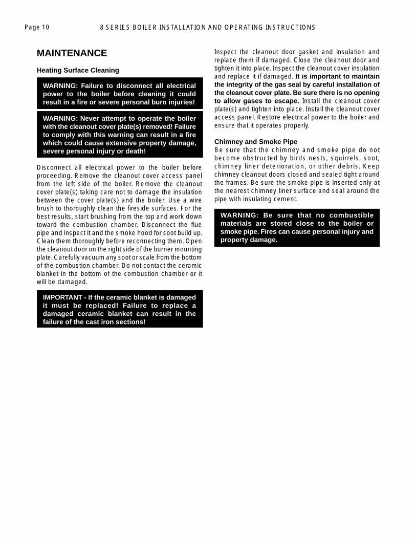
A Special Note to Installers of Water Boiler: All Carlin and Beckett burners, shipped separately under the “Burner In The Box” program do not have a jumper wire installed on the T-T terminals on the primary ignition control. Water boilers require this jumper in order to operate. On water boilers the thermostat is connected to the aquastat relay, on a steam boiler the thermostat will be connected to the T-T terminals on the primay ignition control (see Figure No. 8).
Figure No. 8
8 SERIES BOILER INSTALLATION AND OPERATING INSTRUCTIONS Page 9
DOMESTIC HOT WATER HEATERSTankless domestic hot water heaters are available for water boiler application.
Figure No. 9 – Tankless Heater
Table 1
3
4
5
6
40° to 140°F temp. rise at 180°F boiler water.
DOMESTIC HOT WATER SUPPLY WATER BOILER
No. ofSections
FiringRate
IntermittentDraw (GPM)
ContinuousDraw (GPM)
Low HighLowHighLow HighLowHigh
2.502.503.303.303.804.504.605.00
1.752.002.502.903.303.904.004.90
WATER BOILER MAINTENANCE
CAUTION: Servicing, inspection and adjustment must be done by a trained technician in accordance with all applicable local and national codes. Improper servicing or adjustment can damage the boiler!
The boiler must be cleaned and inspected at least on a year before each heating season. Make sure that the burner and ignition components are free from dust, soot, dirt, corrosion or other deposits that would impair the boiler’s performance.
Safety checks should include, but not limited to, the items listed in the 8 Series Boiler Safety Checklist. This Safety Checklist is included at the end of the manual. A trained technician with a calibrated combustion analyzer should be hired to test and set up the oil burner to assure maximum safety and effi ciency. Consult the manufacturer of each individual safety control for recommendations for service and adjustment.
IMPORTANT - These suggestions cover the boiler maintenance work which will result in the most effi cient operation, the longest useful life of the boiler and the highest return on any investment necessary to carry out the maintenance work.
Water Controls1. WATER PRESSURE: The boiler water pressure must
be suffi cient to maintain a full system and to prevent boiling of the system water. An initial fi ll pressure of 12 psi provides for 18-1/2' of system height. Each additional 2.3' of height requires an additional one pound pressure. Be sure no air is trapped in the boiler, system piping or heating units to impede circulation of the heated boiler water.
2. LOW WATER CUTOFF: Check the Hydrolevel Hydrostat control to be certain the switch opens on water level drop below cutoff point.
3. TEMPERATURE CONTROLS: Check regularly to be sure the controls are functioning to prevent excessive high boiler water temperature.
4. RELIEF VALVES: Conduct regular visual inspection of relief valves to detect signs of corrosive deposits, rust buildup or signs of weeping. It should not weep or discharge water at normal system pressure. NEVER try to clean or repair the relief valve! If valve fails replace it! Replace the valve with a new valve of proper capacity and pressure setting if defective.
H C
COLD WATER SUPPL Y
CHECK VALV E
TEMPERED HO TWATER SUPPL Y
TEMPERING VALVE
OPERATING CONTRO L
8 SERIES BOILER INSTALLATION AND OPERATING INSTRUCTIONSPage 10
MAINTENANCE
Heating Surface Cleaning
WARNING: Failure to disconnect all electrical power to the boiler before cleaning it could result in a fi re or severe personal burn injuries!
WARNING: Never attempt to operate the boiler with the cleanout cover plate(s) removed! Failure to comply with this warning can result in a fi re which could cause extensive property damage, severe personal injury or death!
Disconnect all electrical power to the boiler before proceeding. Remove the cleanout cover access panel from the left side of the boiler. Remove the cleanout cover plate(s) taking care not to damage the insulation between the cover plate(s) and the boiler. Use a wire brush to thoroughly clean the fi reside surfaces. For the best results, start brushing from the top and work down toward the combustion chamber. Disconnect the fl ue pipe and inspect it and the smoke hood for soot build up. Clean them thoroughly before reconnecting them. Open the cleanout door on the right side of the burner mounting plate. Carefully vacuum any soot or scale from the bottom of the combustion chamber. Do not contact the ceramic blanket in the bottom of the combustion chamber or it will be damaged.
IMPORTANT - If the ceramic blanket is damaged it must be replaced! Failure to replace a damaged ceramic blanket can result in the failure of the cast iron sections!
Inspect the cleanout door gasket and insulation and replace them if damaged. Close the cleanout door and tighten it into place. Inspect the cleanout cover insulation and replace it if damaged. It is important to maintain the integrity of the gas seal by careful installation of the cleanout cover plate. Be sure there is no opening to allow gases to escape. Install the cleanout cover plate(s) and tighten into place. Install the cleanout cover access panel. Restore electrical power to the boiler and ensure that it operates properly.
Chimney and Smoke PipeBe sure that the chimney and smoke pipe do not become obstructed by birds nests, squirrels, soot, chimney liner deterioration, or other debris. Keep chimney cleanout doors closed and sealed tight around the frames. Be sure the smoke pipe is inserted only at the nearest chimney liner surface and seal around the pipe with insulating cement.
WARNING: Be sure that no combustible materials are stored close to the boiler or smoke pipe. Fires can cause personal injury and property damage.
8 SERIES BOILER INSTALLATION AND OPERATING INSTRUCTIONS Page 11
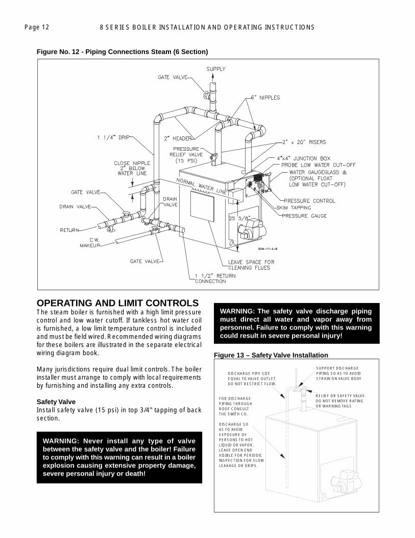
Figure No. 11 - Piping Connections Steam (3-5 Sections)
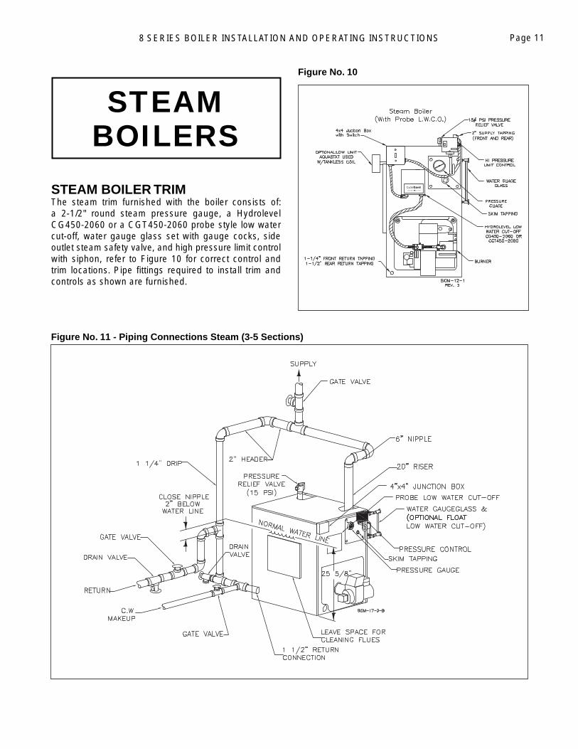
STEAM BOILERS
STEAM BOILER TRIM The steam trim furnished with the boiler consists of: a 2-1/2" round steam pressure gauge, a Hydrolevel CG450-2060 or a CGT450-2060 probe style low water cut-off, water gauge glass set with gauge cocks, side outlet steam safety valve, and high pressure limit control with siphon, refer to Figure 10 for correct control and trim locations. Pipe fi ttings required to install trim and controls as shown are furnished.
Figure No. 10
8 SERIES BOILER INSTALLATION AND OPERATING INSTRUCTIONSPage 12
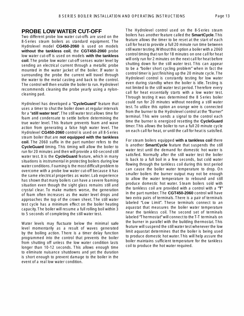
Figure No. 12 - Piping Connections Steam (6 Section)
OPERATING AND LIMIT CONTROLSThe steam boiler is furnished with a high limit pressure control and low water cutoff. If tankless hot water coil is furnished, a low limit temperature control is included and must be fi eld wired. Recommended wiring diagrams for these boilers are illustrated in the separate electrical wiring diagram book.
Many jurisdictions require dual limit controls. The boiler installer must arrange to comply with local requirements by furnishing and installing any extra controls.
Safety ValveInstall safety valve (15 psi) in top 3/4" tapping of back section.
WARNING: Never install any type of valve between the safety valve and the boiler! Failure to comply with this warning can result in a boiler explosion causing extensive property damage, severe personal injury or death!
WARNING: The safety valve discharge piping must direct all water and vapor away from personnel. Failure to comply with this warning could result in severe personal injury!
Figure 13 – Safety Valve Installation
SUPPORT DISCHARGEPIPING SO AS TO AVOIDSTRAIN ON VALVE BODY
FOR DISCHARGEPIPING THROUGHROOF CONSULTTHE SMITH CO.
DISCHARGE SOAS TO AVOIDEXPOSURE OFPERSONS TO HOTLIQUID OR VAPOR.LEAVE OPEN ENDVISIBLE FOR PERIODICINSPECTION FOR SLOWLEAKAGE OR DRIPS.
RELIEF OR SAFETY VALVE.DO NOT REMOVE RATINGOR WARNING TAGS
DISCHARGE PIPE SIZEEQUAL TO VALVE OUTLET.DO NOT RESTRICT FLOW.
8 SERIES BOILER INSTALLATION AND OPERATING INSTRUCTIONS Page 13
PROBE LOW WATER CUT-OFF Two different probe low water cut-offs are used on the 8-Series steam boilers as standard equipment. The Hydrolevel model CG450-2060 is used on models without the tankless coil, the CGT450-2060 probe low water cut-off is used on models with the tankless coil. The probe low water cut-off senses water level by sending an electrical current through a metallic probe mounted in the water jacket of the boiler. If water is surrounding the probe the current will travel through the water to the metal casting and back to the control. The control will then enable the boiler to run. Hydrolevel recommends cleaning the probe yearly using a nylon-cleaning pad.
Hydrolevel has developed a “CycleGuard” feature that uses a timer to shut the boiler down at regular intervals for a “still water test”. The still water test allows time for foam and condensate to settle before determining the true water level. This feature prevents foam and wave action from generating a false high water level. The Hydrolevel CG450-2060 control is used on all 8-Series steam boiler that are not equipped with the tankless coil. The 2060 suffi x in the part number refers to the CycleGuard timing. This timing will allow the boiler to run for 20 minutes and then will provide a 60-second still water test. It is the CycleGuard feature, which in many situations is instrumental in protecting boilers during low water conditions. Foaming is the most diffi cult problem to overcome with a probe low water cut-off because it has the same electrical properties as water. Lab experience has shown that many boilers can have a severe foaming situation even though the sight glass remains still and crystal clear. To make matters worse, the generation of foam often increases as the water level drops and approaches the top of the crown sheet. The still water test cycle has a minimum effect on the boiler heating capacity. The boiler will resume a full rolling boil within 3 to 5 seconds of completing the still water test.
Water levels may fl uctuate below the minimal safe level momentarily as a result of waves generated by the boiling action. There is a timer delay function programmed into the control that prevents the boiler from shutting off unless the low water condition lasts longer than 10-12 seconds. This allows enough time to eliminate nuisance shutdowns and yet the duration is short enough to prevent damage to the boiler in the event of a real low water condition.
The Hydrolevel control used on the 8-Series steam boilers has another feature called the SmartCycle. This feature allows the timer to be reset at the start of each call for heat to provide a full 20 minute run time between still water testing. Without this option a boiler with a 2060 control timing that ran for 18 minutes on one call for heat will only run for 2 minutes on the next call for heat before shutting down for the still water test. This can appear to be a “boiler short cycling problem” when in fact the control timer is just fi nishing up the 20 minute cycle. The Hydrolevel control is constantly testing for low water even during standby when the boiler is idle. Testing is not limited to the still water test period. Therefore every call for heat essentially starts with a low water test. Through testing it was determined the 8 Series boiler could run for 20 minutes without needing a still water test. To utilize this option an orange wire is connected from the burner to the Hydrolevel control at the “Burner” terminal. This wire sends a signal to the control each time the burner is energized resetting the CycleGuard timer. This allows the boiler to run a full 20 minute cycle on each call for heat, or until the call for heat is satisfi ed.
For steam boilers equipped with a tankless coil there is another SmartCycle feature that suspends the still water test until the demand for domestic hot water is satisfi ed. Normally after the still water test the boiler is back to a full boil in a few seconds, but cold water fl owing through the tankless coil during this test period can cause the boiler water temperature to drop. On smaller boilers the burner output may not be enough to allow the water temperature to rebound and still produce domestic hot water. Steam boilers sold with the tankless coil are provided with a control with a “T” in the part number. The CGT450-2060 control will have two extra pairs of terminals. There is a pair of terminals labeled “Low Limit”. These terminals connect to an aquastat that measures the boiler water temperature near the tankless coil. The second set of terminals labeled “Thermostat” will connect to the T-T terminals on the burner in parallel with the building thermostat. This feature will suspend the still water test whenever the low limit aquastat determines that the boiler is being used to produce domestic hot water. This will help assure the boiler maintains suffi cient temperature for the tankless coil to produce the hot water required.
8 SERIES BOILER INSTALLATION AND OPERATING INSTRUCTIONSPage 14
FLOAT LOW WATER CUT-OFFThe fl oat style low water cut-off is only offered as an option on 8-Series boilers. This control consists of a fl oat in a chamber that operates a switch. The chamber is plumbed to the boiler at the minimum safe water level. If the water drops below this level the fl oat opens the switch and turns the burner off. If the switch has a second set of contacts a water feeder can be turned on to automatically refi ll the boiler to the minimum level. This control requires regular maintenance to assure reliability. It is recommended that the fl oat low water cut-off gets “blown down” weekly to prevent the buildup of sediment. The blow down procedure consists of placing a bucket under the device and then opening the blow down valve located on the control while the boiler is under pressure. If the blow-down procedure is neglected sediment can build up under the fl oat holding it at a high water position even though the water level has actually dropped to a dangerous level. The fl oat low water cut-off can fail in a “run” condition when this happens leading to dry fi ring of the boiler. In this event the warranty will be voided. This device will require periodic disassembly for a more thorough cleaning and inspection. The mechanical switches will also need periodic replacing. Consult manufactures literature for recommendations on servicing.
CONSIDERATIONS WHEN USING AUTOMATIC WATER FEEDERS ON STEAM BOILERSEvery steam boiler at some time will need additional makeup water. Water levels need to be controlled on steam boilers to maintain correct steam-chest volume, prevent dry fi ring or fl ooding. Excessively low water levels can cause the iron to overheat creating a “dry fi re “condition. The addition of excessive makeup water can cause the boiler to “fl ood” leading to a host of system problems and damage to personal property.
System leaks that cause a continual loss of water will require the constant addition of makeup water. Dissolved minerals and oxygen are introduced with makeup water and can severely reduce the life of a boiler. Dissolved oxygen in the water can cause internal corrosion of the cast iron leading to sludge formation and leaks. Mineral buildup in conjunction with sludge deposits can reduce the rate of heat transfer through the cast iron causing overheating and cracking, ultimately leading to boiler failure. Leaks must be repaired immediately to prevent this from happening.
The addition of an automatic water feeder can greatly reduce the number of nuisance lockouts due to low water conditions. When selecting a water feeder consideration should be given to preventing boiler fl ooding and the monitoring of water usage as well. A water feeder usually works in conjunction with the Low Water Cut-off by means of the alarm terminals. When the Low Water Cut-off turns off the boiler during a low water condition the alarm terminals are activated. These alarm terminals can be used to turn on the water feeder. The Hydrolevel CycleGard Low Water Cut-off has a 30 second delay between the time the probe detects water and when the alarm terminals are deactivated. If the water feed rate is too great the boiler can be fl ooded during this period. The Hydrolevel VXT-120 (120 Volt model) water feeder works well in conjunction with the CycleGard Low Water Cut-off. It has selection switches that are used to precisely meter the amount of water added, preventing boiler fl ooding. It is equipped with a digital counter that will monitor water usage. This feature can be used to detect increases in water consumption.
FILLING THE SYSTEM (STEAM)Stable water level is a necessity for steam boilers. It is very important to have boiler water free from oil, grease, foaming materials etc. Therefore, fl ush the boiler thoroughly through a bottom drain by introducing clean water into the upper ports of all sections of the boiler. After the boiler piping connections are completed and the boiler can be fi red, the boiler water should be heated up and surface impurities fl ushed off through a high connection (1-1/4" tapping provided in heater cover plate) (see Figures 11 and 12) and then drained through a bottom opening. The burner should not be operated with a low water level in the boiler and makeup water should not be introduced into a hot boiler.
If possible, the heating boiler should be operated for a time with all condensate returning from the system to a drain. This will remove impurities from the piping system which, if not removed early, will eventually enter the boiler and cause problems. In some instances, more than one cleaning will be required to obtain a stable water line.
8 SERIES BOILER INSTALLATION AND OPERATING INSTRUCTIONS Page 15
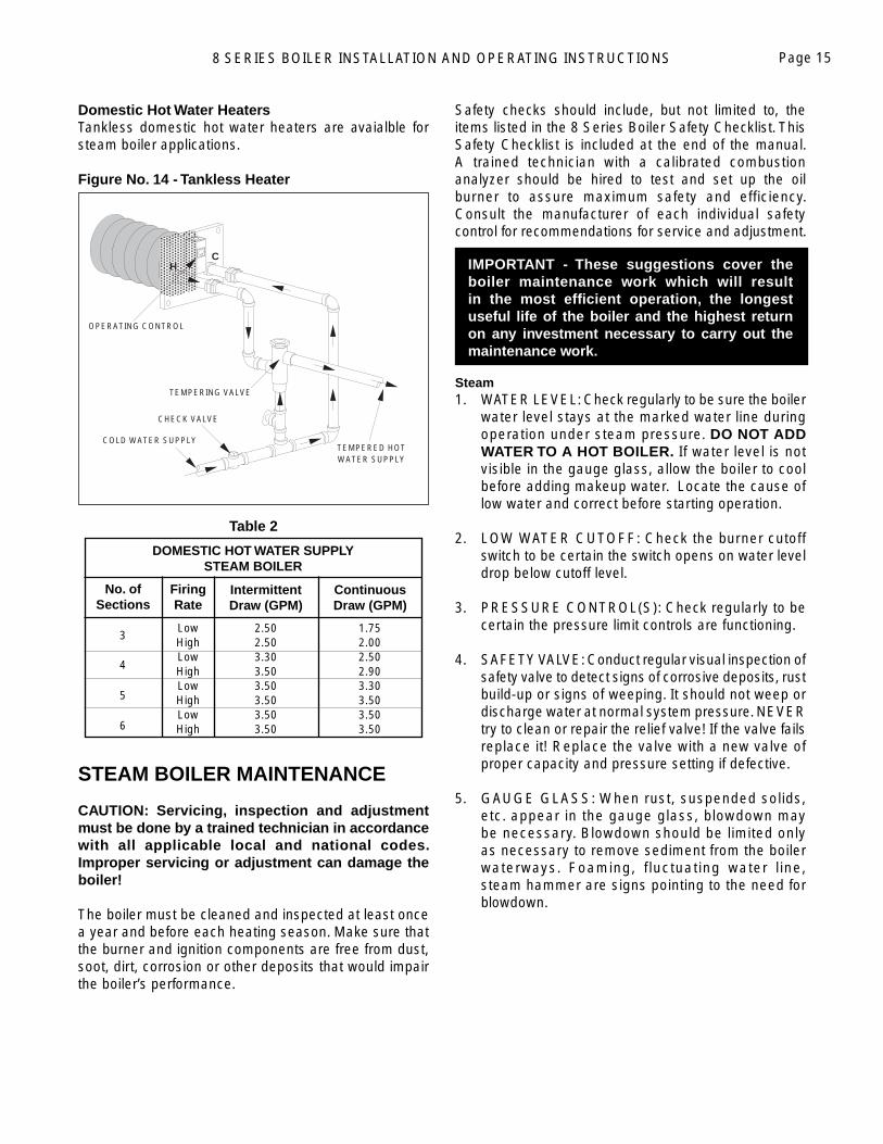
Domestic Hot Water HeatersTankless domestic hot water heaters are avaialble for steam boiler applications.
Figure No. 14 - Tankless Heater
Table 2
STEAM BOILER MAINTENANCE
CAUTION: Servicing, inspection and adjustment must be done by a trained technician in accordance with all applicable local and national codes. Improper servicing or adjustment can damage the boiler!
The boiler must be cleaned and inspected at least once a year and before each heating season. Make sure that the burner and ignition components are free from dust, soot, dirt, corrosion or other deposits that would impair the boiler’s performance.
Safety checks should include, but not limited to, the items listed in the 8 Series Boiler Safety Checklist. This Safety Checklist is included at the end of the manual. A trained technician with a calibrated combustion analyzer should be hired to test and set up the oil burner to assure maximum safety and efficiency. Consult the manufacturer of each individual safety control for recommendations for service and adjustment.
IMPORTANT - These suggestions cover the boiler maintenance work which will result in the most effi cient operation, the longest useful life of the boiler and the highest return on any investment necessary to carry out the maintenance work.
Steam1. WATER LEVEL: Check regularly to be sure the boiler
water level stays at the marked water line during operation under steam pressure. DO NOT ADD WATER TO A HOT BOILER. If water level is not visible in the gauge glass, allow the boiler to cool before adding makeup water. Locate the cause of low water and correct before starting operation.
2. LOW WATER CUTOFF: Check the burner cutoff switch to be certain the switch opens on water level drop below cutoff level.
3. PRESSURE CONTROL(S): Check regularly to be certain the pressure limit controls are functioning.
4. SAFETY VALVE: Conduct regular visual inspection of safety valve to detect signs of corrosive deposits, rust build-up or signs of weeping. It should not weep or discharge water at normal system pressure. NEVER try to clean or repair the relief valve! If the valve fails replace it! Replace the valve with a new valve of proper capacity and pressure setting if defective.
5. GAUGE GLASS: When rust, suspended solids, etc. appear in the gauge glass, blowdown may be necessary. Blowdown should be limited only as necessary to remove sediment from the boiler waterways. Foaming, fluctuating water line, steam hammer are signs pointing to the need for blowdown.
H C
COLD WATER SUPPL Y
CHECK VALV E
TEMPERED HO TWATER SUPPL Y
TEMPERING VALVE
OPERATING CONTRO L
3
4
5
6
DOMESTIC HOT WATER SUPPLY STEAM BOILER
No. ofSections
FiringRate
IntermittentDraw (GPM)
ContinuousDraw (GPM)
Low HighLowHighLow HighLowHigh
2.502.503.303.503.503.503.503.50
1.752.002.502.903.303.503.503.50
8 SERIES BOILER INSTALLATION AND OPERATING INSTRUCTIONSPage 16
8-SERIES WIRINGThe 8-Series boiler comes pre-wired with factory harnesses that connect the safety control system. These boilers are equipped with a harness system utilizing a 6-pin electrical connector that joins the boiler to the burner. Burners from Carlin, Beckett and Riello can be connected to both steam and water boilers utilizing this connector. The harness system is designed to make burner replacement and routine servicing quicker and safer to perform. The high limit control system on this boiler is 120 VAC power. Only trained technicians should attempt to troubleshoot or repair the control system. All power should be turned off before attempting any service work.
When troubleshooting the electrical system on an 8-Series boiler it is only necessary to check the wires that apply to the specifi c burner and boiler combination being used. There may be wires in the harness that are not used for the particular application at hand. These wires have been included to allow for all the various combinations of boiler and burner choices. Consult the Electrical Wiring Book shipped with each boiler for details.
Special Boiler Harness RequirementsOn each boiler there are two harnesses with a 6-pin connector -- the “Boiler Harness”, which is provided by the factory, and the “Burner Harness”, provided by the burner manufacturer. The factory manufactures two different “Boiler Harnesses”:
1. The “Water” harness is primarily used on water boilers but is also found on steam boilers with the optional Float Low Water Cut-off. It runs from the junction box directly to the burner (Part #79004).
2. The “Steam” harness is only used for the steam boiler with the Probe Low Water Cut-off. This harness is shorter and has an additional ORANGE wire used to signal the Cycle Guard timer to reset at the beginning of the call for heat. (See the steam boiler section on the Probe Low Water Cut-off for a description of the Cycle Guard feature). The steam harness runs from the Low Water Cut-off to the burner (Part #79002).
Both boiler harnesses have a RED wire that provides a constant 120V power supply used by the Carlin and Riello burners. This RED wire is always provided, but not used, on boilers equipped with the Beckett burner. The Beckett “Burner Harness will not have a red wire or corresponding pin in the connector.
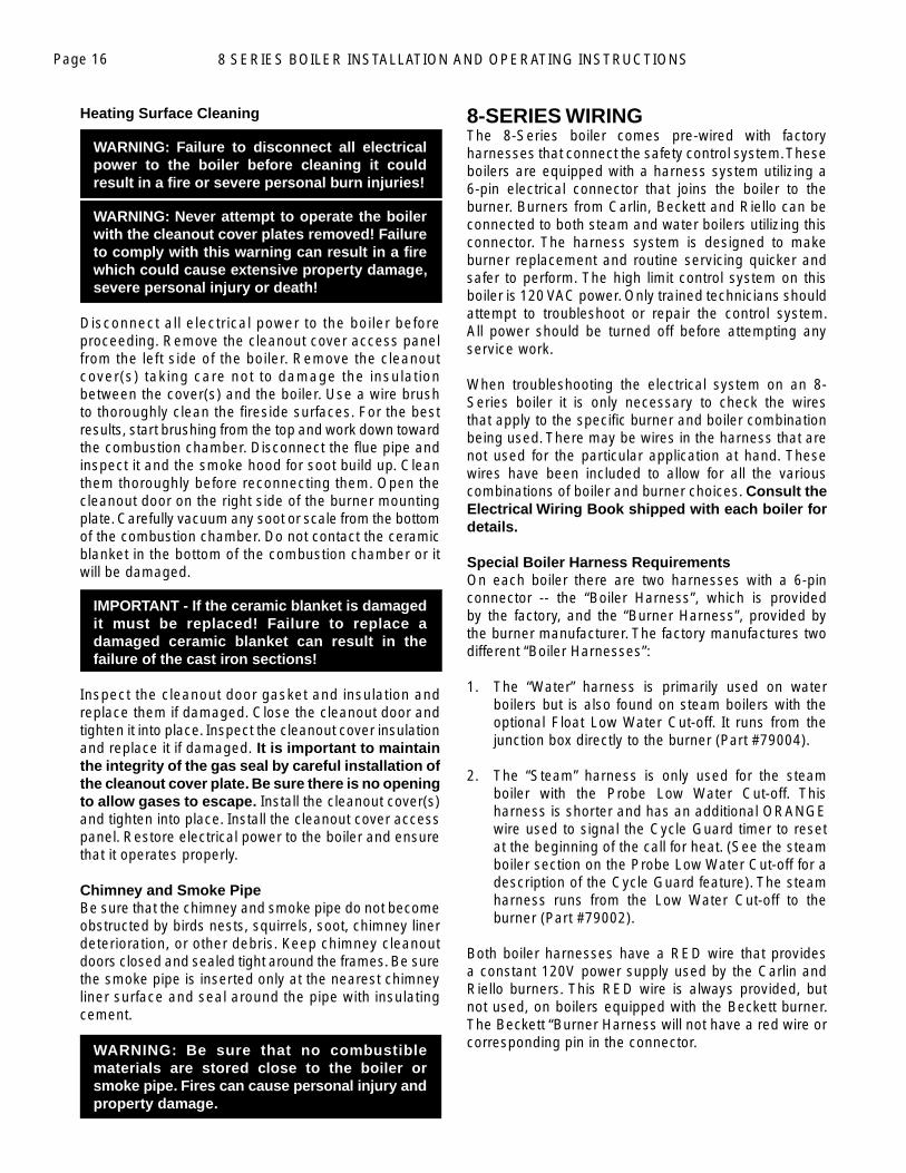
Heating Surface Cleaning
WARNING: Failure to disconnect all electrical power to the boiler before cleaning it could result in a fi re or severe personal burn injuries!
WARNING: Never attempt to operate the boiler with the cleanout cover plates removed! Failure to comply with this warning can result in a fi re which could cause extensive property damage, severe personal injury or death!
Disconnect all electrical power to the boiler before proceeding. Remove the cleanout cover access panel from the left side of the boiler. Remove the cleanout cover(s) taking care not to damage the insulation between the cover(s) and the boiler. Use a wire brush to thoroughly clean the fi reside surfaces. For the best results, start brushing from the top and work down toward the combustion chamber. Disconnect the fl ue pipe and inspect it and the smoke hood for soot build up. Clean them thoroughly before reconnecting them. Open the cleanout door on the right side of the burner mounting plate. Carefully vacuum any soot or scale from the bottom of the combustion chamber. Do not contact the ceramic blanket in the bottom of the combustion chamber or it will be damaged.
IMPORTANT - If the ceramic blanket is damaged it must be replaced! Failure to replace a damaged ceramic blanket can result in the failure of the cast iron sections!
Inspect the cleanout door gasket and insulation and replace them if damaged. Close the cleanout door and tighten it into place. Inspect the cleanout cover insulation and replace it if damaged. It is important to maintain the integrity of the gas seal by careful installation of the cleanout cover plate. Be sure there is no opening to allow gases to escape. Install the cleanout cover(s) and tighten into place. Install the cleanout cover access panel. Restore electrical power to the boiler and ensure that it operates properly.
Chimney and Smoke PipeBe sure that the chimney and smoke pipe do not become obstructed by birds nests, squirrels, soot, chimney liner deterioration, or other debris. Keep chimney cleanout doors closed and sealed tight around the frames. Be sure the smoke pipe is inserted only at the nearest chimney liner surface and seal around the pipe with insulating cement.
WARNING: Be sure that no combustible materials are stored close to the boiler or smoke pipe. Fires can cause personal injury and property damage.
8 SERIES BOILER INSTALLATION AND OPERATING INSTRUCTIONS Page 17
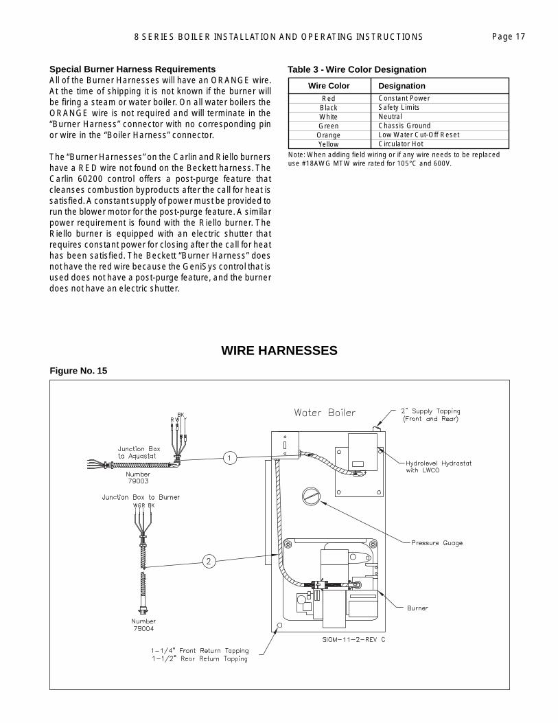
Figure No. 15
Note: When adding fi eld wiring or if any wire needs to be replaced use #18AWG MTW wire rated for 105°C and 600V.
Wire Color Designation
RedBlackWhiteGreenOrange Yellow
Constant PowerSafety LimitsNeutralChassis GroundLow Water Cut-Off ResetCirculator Hot
Special Burner Harness RequirementsAll of the Burner Harnesses will have an ORANGE wire. At the time of shipping it is not known if the burner will be fi ring a steam or water boiler. On all water boilers the ORANGE wire is not required and will terminate in the “Burner Harness” connector with no corresponding pin or wire in the “Boiler Harness” connector.
The “Burner Harnesses” on the Carlin and Riello burners have a RED wire not found on the Beckett harness. The Carlin 60200 control offers a post-purge feature that cleanses combustion byproducts after the call for heat is satisfi ed. A constant supply of power must be provided to run the blower motor for the post-purge feature. A similar power requirement is found with the Riello burner. The Riello burner is equipped with an electric shutter that requires constant power for closing after the call for heat has been satisfi ed. The Beckett “Burner Harness” does not have the red wire because the GeniSys control that is used does not have a post-purge feature, and the burner does not have an electric shutter.
Table 3 - Wire Color Designation
WIRE HARNESSES
8 SERIES BOILER INSTALLATION AND OPERATING INSTRUCTIONSPage 18
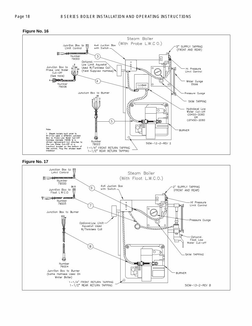
Figure No. 17
Figure No. 16
8 SERIES BOILER INSTALLATION AND OPERATING INSTRUCTIONS Page 19
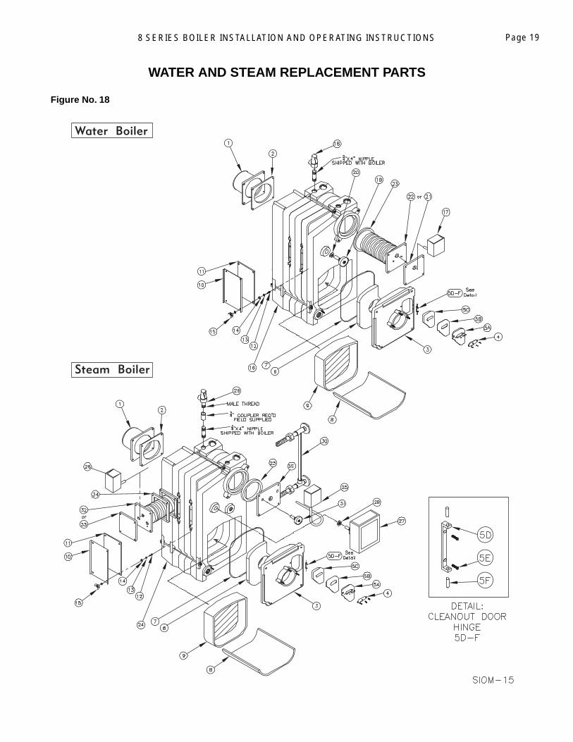
Figure No. 18
WATER AND STEAM REPLACEMENT PARTS
8 SERIES BOILER INSTALLATION AND OPERATING INSTRUCTIONSPage 20
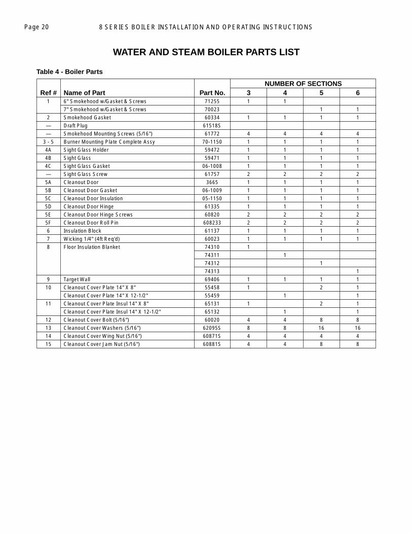
Table 4 - Boiler Parts
WATER AND STEAM BOILER PARTS LIST
1 6" Smokehood w/Gasket & Screws 71255 1 1
7" Smokehood w/Gasket & Screws 70023 1 1
2 Smokehood Gasket 60334 1 1 1 1
— Draft Plug 61518S
— Smokehood Mounting Screws (5/16") 61772 4 4 4 4
3 - 5 Burner Mounting Plate Complete Assy 70-1150 1 1 1 1
4A Sight Glass Holder 59472 1 1 1 1
4B Sight Glass 59471 1 1 1 1
4C Sight Glass Gasket 06-1008 1 1 1 1
— Sight Glass Screw 61757 2 2 2 2
5A Cleanout Door 3665 1 1 1 1
5B Cleanout Door Gasket 06-1009 1 1 1 1
5C Cleanout Door Insulation 05-1150 1 1 1 1
5D Cleanout Door Hinge 61335 1 1 1 1
5E Cleanout Door Hinge Screws 60820 2 2 2 2
5F Cleanout Door Roll Pin 608233 2 2 2 2
6 Insulation Block 61137 1 1 1 1
7 Wicking 1/4" (4ft Req'd) 60023 1 1 1 1
8 Floor Insulation Blanket 74310 1
74311 1
74312 1
74313 1
9 Target Wall 69406 1 1 1 1
10 Cleanout Cover Plate 14" X 8" 55458 1 2 1
Cleanout Cover Plate 14" X 12-1/2" 55459 1 1
11 Cleanout Cover Plate Insul 14" X 8" 65131 1 2 1
Cleanout Cover Plate Insul 14" X 12-1/2" 65132 1 1
12 Cleanout Cover Bolt (5/16") 60020 4 4 8 8
13 Cleanout Cover Washers (5/16") 62095S 8 8 16 16
14 Cleanout Cover Wing Nut (5/16") 60871S 4 4 4 4
15 Cleanout Cover Jam Nut (5/16") 60881S 4 4 8 8
NUMBER OF SECTIONS Ref # Name of Part Part No. 3 4 5 6
8 SERIES BOILER INSTALLATION AND OPERATING INSTRUCTIONS Page 21
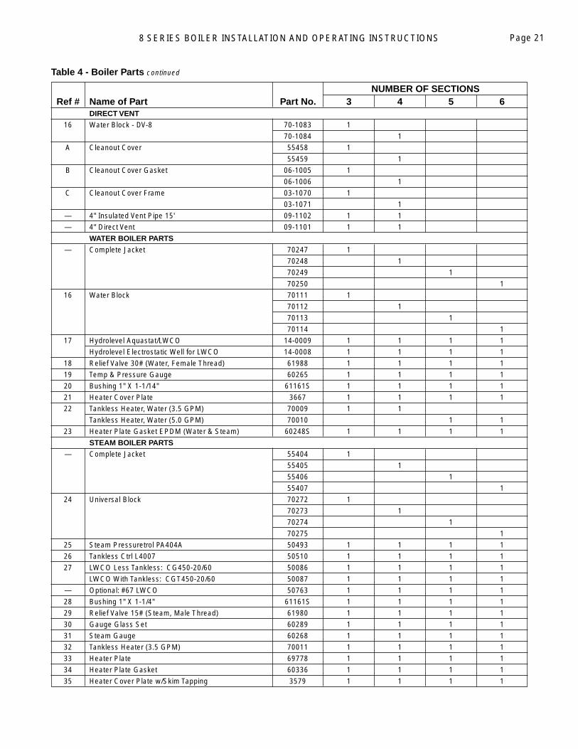
Table 4 - Boiler Parts continued
NUMBER OF SECTIONS Ref # Name of Part Part No. 3 4 5 6 DIRECT VENT
16 Water Block - DV-8 70-1083 1
70-1084 1
A Cleanout Cover 55458 1
55459 1
B Cleanout Cover Gasket 06-1005 1
06-1006 1
C Cleanout Cover Frame 03-1070 1
03-1071 1
— 4" Insulated Vent Pipe 15' 09-1102 1 1
— 4" Direct Vent 09-1101 1 1
WATER BOILER PARTS
— Complete Jacket 70247 1
70248 1
70249 1
70250 1
16 Water Block 70111 1
70112 1
70113 1
70114 1
17 Hydrolevel Aquastat/LWCO 14-0009 1 1 1 1
Hydrolevel Electrostatic Well for LWCO 14-0008 1 1 1 1
18 Relief Valve 30# (Water, Female Thread) 61988 1 1 1 1
19 Temp & Pressure Gauge 60265 1 1 1 1
20 Bushing 1" X 1-1/14" 61161S 1 1 1 1
21 Heater Cover Plate 3667 1 1 1 1
22 Tankless Heater, Water (3.5 GPM) 70009 1 1
Tankless Heater, Water (5.0 GPM) 70010 1 1
23 Heater Plate Gasket EPDM (Water & Steam) 60248S 1 1 1 1
STEAM BOILER PARTS
— Complete Jacket 55404 1
55405 1
55406 1
55407 1
24 Universal Block 70272 1
70273 1
70274 1
70275 1
25 Steam Pressuretrol PA404A 50493 1 1 1 1
26 Tankless Ctrl L4007 50510 1 1 1 1
27 LWCO Less Tankless: CG450-20/60 50086 1 1 1 1
LWCO With Tankless: CGT450-20/60 50087 1 1 1 1
— Optional: #67 LWCO 50763 1 1 1 1
28 Bushing 1" X 1-1/4" 61161S 1 1 1 1
29 Relief Valve 15# (Steam, Male Thread) 61980 1 1 1 1
30 Gauge Glass Set 60289 1 1 1 1
31 Steam Gauge 60268 1 1 1 1
32 Tankless Heater (3.5 GPM) 70011 1 1 1 1
33 Heater Plate 69778 1 1 1 1
34 Heater Plate Gasket 60336 1 1 1 1
35 Heater Cover Plate w/Skim Tapping 3579 1 1 1 1
8 SERIES BOILER INSTALLATION AND OPERATING INSTRUCTIONSPage 22
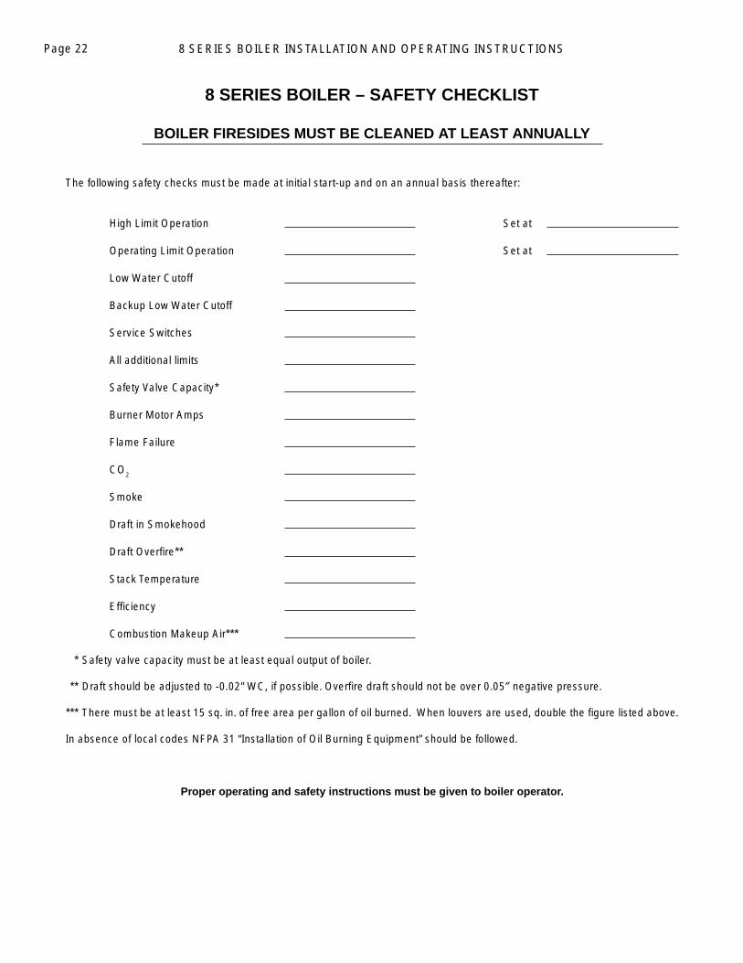
8 SERIES BOILER – SAFETY CHECKLIST
BOILER FIRESIDES MUST BE CLEANED AT LEAST ANNUALLY
The following safety checks must be made at initial start-up and on an annual basis thereafter:
High Limit Operation Set at
Operating Limit Operation Set at
Low Water Cutoff
Backup Low Water Cutoff
Service Switches
All additional limits
Safety Valve Capacity*
Burner Motor Amps
Flame Failure
CO2
Smoke
Draft in Smokehood
Draft Overfi re**
Stack Temperature
Effi ciency
Combustion Makeup Air***
*** Safety valve capacity must be at least equal output of boiler.
*** Draft should be adjusted to -0.02" WC, if possible. Overfi re draft should not be over 0.05″ negative pressure.
*** There must be at least 15 sq. in. of free area per gallon of oil burned. When louvers are used, double the fi gure listed above.
In absence of local codes NFPA 31 “Installation of Oil Burning Equipment” should be followed.
Proper operating and safety instructions must be given to boiler operator.
8 SERIES BOILER INSTALLATION AND OPERATING INSTRUCTIONS Page 23
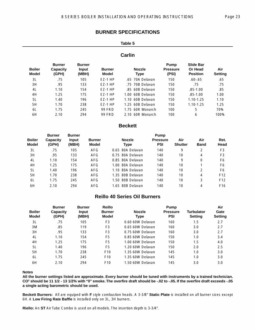
BURNER SPECIFICATIONS
Table 5
Carlin Burner Burner Pump Slide Bar Boiler Capacity Input Burner Nozzle Pressure Or Head Air Model (GPH) (MBH) Model Type (PSI) Position Setting
3L .75 105 EZ-1 HP .65 70A Delavan 150 .60-.65 .65 3H .95 133 EZ-1 HP .75 70B Delavan 150 .75 .75 4L 1.10 154 EZ-1 HP .85 60B Delavan 150 .85-1.00 .85 4H 1.25 175 EZ-1 HP 1.00 60B Delavan 150 .85-1.00 1.00 5L 1.40 196 EZ-1 HP 1.10 60B Delavan 150 1.10-1.25 1.10 5H 1.70 238 EZ-1 HP 1.25 60B Delavan 150 1.10-1.25 1.25 6L 1.75 245 99 FRD 1.75 60R Monarch 100 5 70% 6H 2.10 294 99 FRD 2.10 60R Monarch 100 6 100%
Beckett Burner Burner Pump Boiler Capacity Input Burner Nozzle Pressure Air Air Ret. Model (GPH) (MBH) Model Type PSI Shutter Band Head
3L .75 105 AFG 0.65 80A Delavan 140 9 2 F3 3H .95 133 AFG 0.75 80A Delavan 140 10 4 F3 4L 1.10 154 AFG 0.85 80A Delavan 140 9 0 F6 4H 1.25 175 AFG 1.00 80A Delavan 140 10 1 F6 5L 1.40 196 AFG 1.10 80A Delavan 140 10 2 F6 5H 1.70 238 AFG 1.35 80B Delavan 140 10 4 F12 6L 1.75 245 AFG 1.50 80B Delavan 140 10 3 F12
6H 2.10 294 AFG 1.65 80B Delavan 140 10 4 F16
Reillo 40 Series Oil Burners Burner Burner Reillo Pump Air Boiler Capacity Input Burner Nozzle Pressure Turbulator Gate Model (GPH) (MBH) Model Type PSI Setting Setting
3L .75 105 F3 0.60 60W Delavan 160 1.5 2.7 3M .85 119 F3 0.65 60W Delavan 160 3.0 2.7 3H .95 133 F3 0.75 60W Delavan 160 3.0 2.7 4L 1.10 154 F5 0.85 60W Delavan 150 1.0 3.4 4H 1.25 175 F5 1.00 60W Delavan 150 1.5 4.0 5L 1.40 196 F5 1.20 60W Delavan 150 2.0 2.5 5H 1.70 238 F10 1.35 60W Delavan 145 1.0 3.0 6L 1.75 245 F10 1.35 60W Delavan 145 1.0 3.0
6H 2.10 294 F10 1.50 60W Delavan 145 3.0 3.0
Notes All the burner settings listed are approximate. Every burner should be tuned with instruments by a trained technician. CO2 should be 11 1/2 - 13 1/2% with “0” smoke. The overfi re draft should be -.02 to -.05. If the overfi re draft exceeds -.05 a single acting barometric should be used. Beckett Burners: All are equiped with F style combustion heads. A 3-3/8" Static Plate is installed on all burner sizes except 6H. A Low Firing Rate Baffl e is installed only on 3L, 3H burners. Riello: An ST Air Tube Combo is used on all models. The insertion depth is 3-3/4".
Page 24
dizzinessheadachesnausea
vision problemsloss of muscle controlweakness
shortness of breathunclear thinkingunconsciousness
WARNINGAny appliance that burns natural gas, propane gas, fuel oil, wood or coal is capable of producing carbon monoxide (CO).
Carbon Monoxide (CO) is a gas which is odorless, colorless and tasteless but is very toxic.
If your Smith boiler is not working properly, or is not vented properly, dangerous levels of CO may accumulate. CO is lighter than air and thus may travel throughout the building. BRIEF EXPOSURE TO HIGH CONCENTRATIONS OF CO, OR PROLONGED EXPOSURE TO LESSER AMOUNTS OF CO MAY RESULT IN CARBON MONOXIDE POISONING.
EXPOSURE CAN BE FATAL AND EXPOSURE TO HIGH CONCENTRATIONS MAY RESULT IN THE SUDDEN ONSET OF SYMPTOMS INCLUDING UNCONSCIOUSNESS.
Symptoms of CO poisoning include the following:
The symptoms of CO poisoning are often confused with those of infl uenza, and the highest incidence of poisoning occurs at the onset of cold weather or during fl u season. A victim may not experience any symptoms, only one symptom, or a few symptoms. Suspect the presence of carbon monoxide if symptoms tend to disappear when you leave your home.
The following signs may indicate the presence of carbon monoxide: • Hot gases from appliance, venting system, pipes or chimney, escaping into the living space. • Flames coming out around the appliance. • Yellow colored fl ames in the appliance. • Stale or smelly air. • The presence of soot or carbon in or around the appliance. • Very high unexplained humidity inside the building.
If any of the symptoms of CO poisoning occur, or if any of the signs of carbon monoxide are present, VACATE THE PREMISES IMMEDIATELY AND CONTACT A QUALIFIED HEATING SERVICE COMPANY OR THE GAS COMPANY OR THE FIRE DEPARTMENT.
To reduce the risk of CO poisoning, have your heating system “tuned up” by a licensed heating contractor or the gas company - preferably before each heating season. Also have the service company check your chimney or vent pipes for blockage.
Your home should also be adequately ventilated, particularly if you have insulated your home.
ONLY QUALIFIED, LICENSED SERVICE CONTRACTORS SHOULD PERFORM WORK ON YOUR SMITH BOILER!
WARNINGInstall, operate and maintain unit in accordance with manufacturer’s instructions to avoid exposure to fuel substances or substances from incomplete combustion which can cause death or serious illness. The State of California has determined that these substances may cause cancer, birth defects, or other reproductive harm. Also, install and service this product to avoid exposure to airborne particles of glasswool fi bers and/or ceramic fi bers known to the State of California to cause cancer through inhalation.
Page 25STEAM WARRANTIES
LIMITED WARRANTY FOR RESIDENTIAL CAST IRON HEATING BOILERS
This warranty statement is effective after December 15, 1992 and supersedes all other warranties, including those contained in other documents which might be included with this merchandise. The warranty applies only to the original owner at the original place of installation.
Westcast, Inc. warrants to the homeowner at the original place of installation that the cast iron boiler sections were free of defects in material and workmanship when shipped, and will remain free of defects under normal usage from the date of original boiler lightoff, for a period of ten years.
In the event that the boiler sections, upon examination by Westcast should be proven to the satisfaction of Westcast, Inc. to be defective in material or workmanship during the warranty period, Westcast will repair or replace at its option the defective cast iron sections.
The homeowner should perform the following in order to insure prompt warranty service:1. Notify the installer, who in turn should notify the distributor, promptly upon discovery of a condition believed to be
caused by a defect in manufacture. Failing this, the owner should notify Westcast, Inc. 260 North Elm Street, Westfi eld, Massachusetts 01085 in writing, giving full particulars in support of the claim.
2. Make available for inspection to Westcast or its representative the parts alleged to be defective.,and if requested by Westcast, Inc. ship said parts prepaid to Westcast, Inc. 201 West Spring Street, Boyertown, PA, 19512 for inspection or repair.
EXCEPTIONS AND EXCLUSIONS
1. This Warranty covers cast iron boiler sections only. Other cast iron parts such as, but not limited to the burner mounting plate and smokehood are specifi cally not warranted. The burner, jacket, controls and other auxiliary equipment furnished by Westcast, Inc. but purchased from others shall be limited to that manufacturer's warranty, if any.
2. This Warranty does not include expenses for removal or reinstallation. The user will be responsible for the cost of replacement of the defective part, and all labor and material necessary to the exchange. Replacement material will be invoiced to the Distributor in the usual manner and will be subject to adjustment upon proof of defect.
3. Nothing herein shall be constructed as a guaranty of workmanship of any installer in installing Westcast, Inc. cast iron boilers, or as imposing on the Company any liability of any nature for unsatisfactory performance caused by faulty workmanship in installation, which liability is expressly disclaimed.
4. This Warranty will not apply if the boiler is structurally altered; is used or operated at over its rated capacity; or is not maintained in accordance with Westcast, Inc.'s recommendations or the accepted good practice of the industry as defi ned by the Hydronics Institute, A.S.M.E. or other accepted authority.
5. This Warranty will not apply if the boiler has been damaged as a result of: fi re or other casualites; fl ooding or exposure to the elements; settlement, distortion, collapse or cracking of any foundation area, beams or pipes surrounding the boiler; improper or negligent installation, service or operation (including but not limited to the following — operated with insuffi cient water, allowed to freeze; subject to fl ood conditions; or operated with water conditions and/or fuels or additives which have caused unusual deposits or corrosion in or on the cast sections).
6. This Warranty applies only to boilers installed within the continental limits of the United States and Canada.7. In order for this Warranty to be effective:
A. The boiler must have been assembled in a single or two-family residential dwelling. This Warranty does not applyto boilers installed in apartments, commercial or industrial installation.
B. The boiler must have been properly installed in strict accordance with Westcast, Inc. Installation Instructions furnishedwith the boiler.
C. Boiler sections must not have been damaged in handling shipment or installation. The determination of damage inhandling or installation is considered judgement of Westcast, Inc. and such decision shall be fi nal.
D. The boiler must have been serviced annually by a licensed contractor and proof of such service must be provided with warranty claim. This service must include but is not limited to fi reside cleaning and proper burner adjustment
with combustion testing.8. In no case shall Westcast, Inc.'s liability exceed the original selling price of the product found to be defective.9. THIS WARRANTY IS IN LIEU OF ALL EXPRESS WARRANTIES OF ANY KIND. THE REMEDIES UNDER THIS WARRANTY
ARE EXCLUSIVE AND WESTCAST, INC. NEITHER ASSUMES NOR AUTHORIZES ANYONE TO ASSUME FOR IT ANY OTHER OBLIGATIONS. IN NO EVENT SHALL WESTCAST, INC. BE LIABLE UNDER WHIS WARRANTY OR OTHERWISE IN ANY MANNER FOR ANY INCIDENTAL, REMOTE OR CONSEQUENTIAL DAMAGES RESULTING FROM BREACH OF THIS WARRANTY OR CONDITION IMPLIED BY LAW OR OTHERWISE, INCLUDING ANY IMPLIED WARRANTY OF MERCHANTABILITY OR FITNESS. SOME STATES DO NOT ALLOW THE EXCLUSION OR LIMITATION OF INCIDENTAL OR CONSEQUENTIAL DAMAGES, SO THE ABOVE LIMITATION OR EXCLUSION MAY NOT APPLY TO YOU.
10. This warranty gives you specifi c legal rights, and you may also have other rights which vary from state to state.
Page 26 LIMITED LIFETIME WARRANTY FOR RESIDENTIAL WATER BOILERS (Excluding GT & GX)
This warranty statement is effective for all units manufactured after December 15, 1992 and supersedes all other warranties, including those contained in other documents which might be included with this merchandise. This warranty applies only to the original homeowner at the original place of installation.
First Through Tenth YearWestcast, Inc. warrants that the cast iron sections of its residential water boiler for Smith Cast Iron Boilers were free of defects in material and workmanship when shipped, and will remain free of defects under normal usage from the date of original installation, for a period of ten years. In the event that the cast iron section is found to be defective in material or workmanship during this period, Westcast, Inc. will repair or replace, at its option, the defective section.
Eleventh Year and AboveWestcast, Inc. warrants that the cast iron sections of its residential water boilers will remain free of defects in material and workmanship under normal usage for the lifetime of the original owner at the original place of installation. Should any sections be found to be defective, Westcast, Inc. will repair or replace, at its option, the original cast iron sections upon the payment of a proportionate charge based on the time the defective section was in service. The proportionate charge will be equal to the appropriate percentage of the retail price of the section at the time the warranty claim is made, determined as follows:
Year 11th 12th 13th 14th 15th 16th 17th 18th 19th 20th 21st 22nd 23nd 24th 25th & above
% ofRetail
5 10 15 20 25 30 35 40 45 50 55 60 65 70 75
Price
Procedure for Obtaining Warranty Service
The homeowner should perform the following in order to insure prompt warranty service:1. Notify the installer, who in turn should notify the distributor, promptly upon discovery of a condition believed to be caused
by a defect in manufacture. Following this, the owner should notify Westcast, Inc., 260 North Elm St., Westfi eld, MA 01085 in writing, giving full particulars in support of the claim.
2. Make available for inspection to Westcast, Inc. or its representative the parts alleged to be defective, and if requested by Westcast, Inc., ship said parts prepaid to Westcast, Inc., 201 West Spring Street, Boyertown, PA 19512 for inspection or repair.
Exceptions and Exclusions1. This Warranty covers cast iron boiler sections only. Other cast iron parts such as but not limited to the burner mounting
plate and smokehood are specifi cally not warranted. The burner, jacket, controls and other auxiliary equipment furnished by Westcast, Inc., but purchased from others shall be limited to that manufacturer's warranty, if any. (Typically one year for parts)
2. This Warranty does not include expenses for removal or re-installation. The user will be responsible for the cost of replacement of the defective part and labor and material necessary to the exchange. Replacement material will be invoiced to the Distributor in the usual manner and will be subject to adjustment upon proof of defect.
3. Nothing herein shall be construed as a guaranty of workmanship of any installer in installing Westcast, Inc. cast iron boilers, or as imposing on the Company any liability of any nature for unsatisfactory performance caused by faulty workmanship in installation, which liability is expressly disclaimed.
4. This Warranty will not apply if the boiler is structurally altered; is used or operated at over its rated capacity; or is not maintained in accordance with Westcast, Inc.'s recommendations or the accepted good practice of the industry as defi ned by the Hydronics Institute, A.S.M.E. or other accepted authority.
5. This Warranty will not apply if the boiler has been damaged a result of: fi re or other casualties; fl ooding or exposure to the elements; settlement, distortion, collapse or cracking of any foundation area, beams or pipes surrounding the boiler; improper or negligent installation, service or operation (including but not limited to the following - operated with insuffi cient water, allowed to freeze; subject to fl ood conditions; or operated with water conditions and/or fuels or additives which have caused unusual deposits or corrosion in or on the cast sections).
6. This Warranty applies only to boilers installed within the United States and Canada.7. In order for this Warranty to be effective:
A. The boiler must have been properly installed in a single or two-family residential dwelling. Warranty does not apply to boilers installed in apartments, commercial or industrial installations. When installed in a commercial application, the boiler will be warranted for one year.
B. The boiler must have been assembled in strict accordance with Westcast, Inc. installation instructions furnished with the boiler.C. Boiler sections must not have been damaged in handling during shipment or installation. The determination of damage
in handling or installation is a considered judgement of Westcast, Inc. and decision shall be fi nal.D. The boiler must have been serviced annually by a licensed contractor and proof of such service must be provided
with warranty claim. This service must include but is not limited to fi reside cleaning and proper burner adjustment with combustion testing.
8. In no case shall Westcast, Inc.'s liability exceed the original selling price of the product found to be defective.9. THIS WARRANTY IS IN LIEU OF ALL EXPRESS WARRANTIES OF ANY KIND. THE REMEDIES UNDER THIS WARRANTY
ARE EXCLUSIVE AND WESTCAST, INC. NEITHER ASSUMES NOR AUTHORIZES ANYONE TO ASSUME FOR IT ANY OTHER OBLIGATIONS. IN NO EVENT SHALL WESTCAST, INC. BE LIABLE UNDER THIS WARRANTY OR OTHERWISE IN ANY MANNER FOR ANY INCIDENTAL, REMOTE OR CONSEQUENTIAL DAMAGES RESULTING FROM BREACH OF THIS WARRANTY OR CONDITION IMPLIED BY LAW OR OTHERWISE, INCLUDING ANY IMPLIED WARRANTY OF MERCHANTABILITY OR FITNESS, FOR A PARTICULAR PURPOSE. SOME STATES DO NOT ALLOW THE EXCLUSION OR LIMITATION OF INCIDENTAL OR CONSEQUENTIAL DAMAGES, SO THE ABOVE LIMITATION OR EXCLUSION MAY NOT APPLY TO YOU.
10. This Warranty gives you specifi c legal rights, and you may also have other rights which vary from state to state.

8 SERIES BOILER INSTALLATION AND OPERATING INSTRUCTIONS Page 27

WESTCAST, INC. 260 NORTH ELM STREET 7555 TRANMERE DRIVE WESTFIELD, MA 01085 MISSISSAUGA,ONTARIO L5S 1L4 TEL. (413) 562-9631 FAX (413) 562-3799 TEL. (905) 672-2991 FAX (905) 672-2883