Embed Size (px)
Citation preview
International Journal of Mechanical Engineering and Technology (IJMET), ISSN 0976 –
6340(Print), ISSN 0976 – 6359(Online) Volume 3, Issue 3, Sep- Dec (2012) © IAEME
84
EXPERIMENTAL INVESTIGATION OF SINGLE CYLINDER 4S SI
ENGINE WITH HYDROGEN BLENDS
Suhas B.G
1, Shivaprasad K.V
2, Kumar G.N
3
1 M Tech Candidate, Mechanical Engineering Department, National Institute of Technology
Karnataka, Surathkal, Mangalore. 2
PhD Candidate, Mechanical Engineering Department, National Institute of Technology
Karnataka, Surathkal, Mangalore. 3
Assistant Professor, Mechanical Engineering Department, National Institute of Technology
Karnataka, Surathkal, Mangalore.
ABSTRACT
Considering energy crises and pollution problems today much work has been done for alternative
fuels for fossil fuels and lowering the toxic components in the combustion products. The present
investigation is to find performance and emission characteristics of a single cylinder spark
ignition engine operating with hydrogen blends. The hydrogen is blended in different volume
fraction of 3%, 6%, 9% and 12% of petrol in a four stroke single cylinder Villiers’s engine for
different load. The load is varied from no load to full load in steps of one fourth, half and three
forth of the full load. The engine in which the experiment to be conducted is a constant speed
engine. The performance and emissions of engine such as, brake thermal efficiency, brake
specific energy consumption, volumetric Efficiency, exhaust gas temperature, carbon monoxide,
unburnt hydrocarbons and oxides of nitrogen are to be determined and compared with base line
readings of petrol.
Keywords: Back Fire, Brake specific energy consumption, Brake thermal efficiency, Emissions,
Exhaust gas temperature, Hydrogen and Volumetric efficiency.
1. INTRODUCTION
Fossil fuels such as petroleum, natural gas and coal meet most of the world’s energy demand, at
present time. But combustion products of these fossil fuels, such as carbon monoxide (CO),
carbon dioxide (CO2), oxides of sulfur (SOx), and oxides of nitrogen (NOx), hydrocarbon (HC),
toxic metals, and ashes have been causing many environmental problems and posing great
INTERNATIONAL JOURNAL OF MECHANICAL ENGINEERING AND
TECHNOLOGY (IJMET)
ISSN 0976 – 6340 (Print)
ISSN 0976 – 6359 (Online)
Volume 3, Issue 3, Septmebr - December (2012), pp. 84-95
© IAEME: www.iaeme.com/ijmet.html
Journal Impact Factor (2012): 3.8071 (Calculated by GISI)
www.jifactor.com
IJMET
© I A E M E
International Journal of Mechanical Engineering and Technology (IJMET), ISSN 0976 –
6340(Print), ISSN 0976 – 6359(Online) Volume 3, Issue 3, Sep- Dec (2012) © IAEME
85
danger for the world. Hydrogen has proved its suitability over many fuels in these criteria.
Hydrogen does not cause combustion problems such as vapor lock, cold wall quenching,
inadequate vaporization or poor mixing, and do not produce toxic products [1]. The limited fossil
fuel resources and toxic emissions exhausted from internal combustion (IC) engines have pushed
the researches to focus on alternative fuels. Meanwhile, the high adiabatic flame speed of
hydrogen indicates that the combustion of hydrogen engines is much closer to ideal constant
volume combustion, which is beneficial for higher thermal efficiency. Since the energy density
of hydrogen on volume basis is much lower than that of gasoline, the hydrogen powered engines
sometimes also suffer a weak torque output [2]. Hydrogen has special properties so the
combustion characteristics of hydrogen are very different from gasoline. The laminar flame
speed of a hydrogen air mixture at stoichiometric condition is about ten times that of gasoline.
The wide flammability limit of hydrogen allows the use of very low equivalence ratios which
result in reducing NOx emissions. The octane rating of hydrogen of 106 RON allows increasing
compression ratio. Hydrogen is renewable and offers lots of other benefits. The most practical
one is its ability to run in bi-fuel conditions [3]. The limited fossil fuel reserves and increased air
pollution have pushed studies on improving the thermal efficiency and emissions performance of
internal combustion (IC) engines. Because of the decreased combustion temperature and reduced
charge homogeneity, spark-ignited (SI) engines always expel large amounts of HC and CO
emissions at cold start [4]. Hydrogen is widely regarded as a promising transportation fuel
because it is clean and renewable. While electrochemically reacting hydrogen in fuel cells is
considered to be the cleanest and most efficient means of using hydrogen, it is believed by many
to be a technology of the distant future. One of the main obstacles that plagued the successful
utilization of hydrogen as a fuel in an ICE has been pre-ignition. This phenomenon is due to the
undesirable combustion of the air/fuel charge in the intake manifold [5]. The hydrogen engine is
a possible solution to improving the engine performance at idle and lean conditions. Since the
flame speed of hydrogen is five times as large as that of gasoline, hydrogen engines can get a
high degree of constant volume combustion which not only benefits the engine thermal
efficiency but also reduces the engine cyclic variation. Besides, the low ignition energy of
hydrogen also permits hydrogen-air mixture to be easily ignited under lean conditions and helps
engines gain a smooth starting process. But increased NOx emissions and reduced power output
of hydrogen engines, it is hard for the pure hydrogen-fueled engines to be widely
commercialized in the near future [6]. The unique combustion characteristics of hydrogen that
allow clean and efficient operation at low engine loads present difficulties at high engine loads.
Here, the low ignition energies of hydrogen–air mixtures cause frequent unscheduled combustion
events, and high combustion temperatures of mixtures closer to the stoichiometric composition
lead to increased NOx production [7]. The main feature of hydrogen as a fuel is that it does not
occur in its free state naturally. Hydrogen can be produced from fossil fuels such as natural gas,
oil and coal, mainly via their reforming with steam or through partial oxidation. Such fuel
mixtures of widely varying composition are processed usually further to increase the purity of
the hydrogen produced, whether for applications in the chemical and petrochemical industry or
for combustion in conventional power and heating devices. The important application of
hydrogen to fuel cells, ultra-high-purity hydrogen is required which makes the hydrogen
produced by these methods often of unacceptable quality [8].
International Journal of Mechanical Engineering and Technology (IJMET), ISSN 0976 –
6340(Print), ISSN 0976 – 6359(Online) Volume 3, Issue 3, Sep- Dec (2012) © IAEME
86
2. EXPERIMENTAL SETUP AND METHODOLOGY
2.1 Experimental procedure
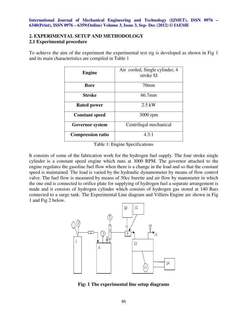
To achieve the aim of the experiment the experimental test rig is developed as shown in Fig 1
and its main characteristics are compiled in Table 1
Engine Air cooled, Single cylinder, 4
stroke SI
Bore 70mm
Stroke 66.7mm
Rated power 2.5 kW
Constant speed 3000 rpm
Governor system Centrifugal mechanical
Compression ratio 4.3:1
Table 1: Engine Specifications
It consists of some of the fabrication work for the hydrogen fuel supply. The four stroke single
cylinder is a constant speed engine which runs at 3000 RPM. The governor attached to the
engine regulates the gasoline fuel flow when there is a change in the load and so that the constant
speed is maintained. The load is varied by the hydraulic dynamometer by means of flow control
valve. The fuel flow is measured by means of 50cc burette and air flow by manometer in which
the one end is connected to orifice plate for supplying of hydrogen fuel a separate arrangement is
made and it consists of hydrogen cylinder which consists of hydrogen gas stored at 140 Bars
connected to a surge tank. The Experimental Line diagram and Villiers Engine are shown in Fig
1 and Fig 2 below.
Fig: 1 The experimental line setup diagrams
International Journal of Mechanical Engineering and Technology (IJMET), ISSN 0976 –
6340(Print), ISSN 0976 – 6359(Online) Volume 3, Issue 3, Sep- Dec (2012) © IAEME
87
(1) Hydrogen gas cylinder at 140 Bars (2) Two stage pressure regulators (3) Non return valve (4)
Surge tank (5) Pressure indicator of surge tank (6) Safety valve (7) Rotameter (8) Line pressure
indicator (9) Carburetor (10) Gasoline tank (11) Orifice plate contained in an air box (12) Engine
cylinder (13) Engine piston connecting rod (14) Hydraulic dynamometer (15) Exhaust manifold
(16) K type Thermocouple.
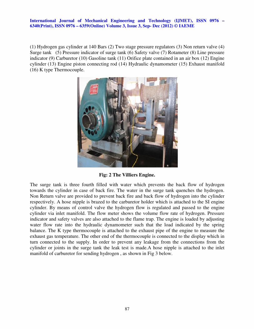
Fig: 2 The Villiers Engine.
The surge tank is three fourth filled with water which prevents the back flow of hydrogen
towards the cylinder in case of back fire. The water in the surge tank quenches the hydrogen.
Non Return valve are provided to prevent back fire and back flow of hydrogen into the cylinder
respectively. A hose nipple is brazed to the carburetor holder which is attached to the SI engine
cylinder. By means of control valve the hydrogen flow is regulated and passed to the engine
cylinder via inlet manifold. The flow meter shows the volume flow rate of hydrogen. Pressure
indicator and safety valves are also attached to the flame trap. The engine is loaded by adjusting
water flow rate into the hydraulic dynamometer such that the load indicated by the spring
balance. The K type thermocouple is attached to the exhaust pipe of the engine to measure the
exhaust gas temperature. The other end of the thermocouple is connected to the display which in
turn connected to the supply. In order to prevent any leakage from the connections from the
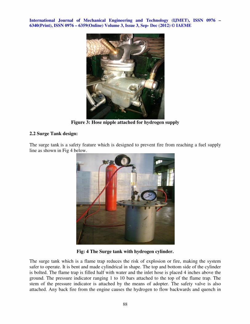
cylinder or joints in the surge tank the leak test is made.A hose nipple is attached to the inlet
manifold of carburetor for sending hydrogen , as shown in Fig 3 below.
International Journal of Mechanical Engineering and Technology (IJMET), ISSN 0976 –
6340(Print), ISSN 0976 – 6359(Online) Volume 3, Issue 3, Sep- Dec (2012) © IAEME
88
Figure 3: Hose nipple attached for hydrogen supply
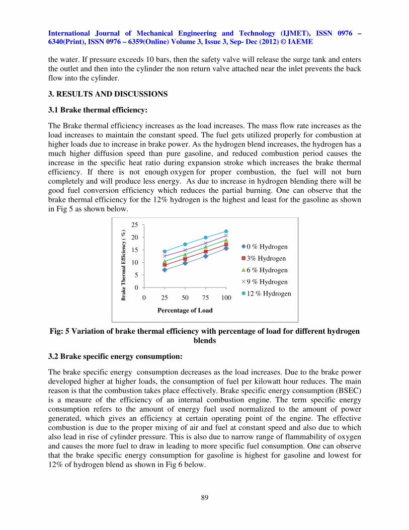
2.2 Surge Tank design:
The surge tank is a safety feature which is designed to prevent fire from reaching a fuel supply
line as shown in Fig 4 below.
Fig: 4 The Surge tank with hydrogen cylinder.
The surge tank which is a flame trap reduces the risk of explosion or fire, making the system
safer to operate. It is bent and made cylindrical in shape. The top and bottom side of the cylinder
is bolted. The flame trap is filled half with water and the inlet hose is placed 4 inches above the
ground. The pressure indicator ranging 1 to 10 bars attached to the top of the flame trap. The
stem of the pressure indicator is attached by the means of adopter. The safety valve is also
attached. Any back fire from the engine causes the hydrogen to flow backwards and quench in
International Journal of Mechanical Engineering and Technology (IJMET), ISSN 0976 –
6340(Print), ISSN 0976 – 6359(Online) Volume 3, Issue 3, Sep- Dec (2012) © IAEME
89
the water. If pressure exceeds 10 bars, then the safety valve will release the surge tank and enters
the outlet and then into the cylinder the non return valve attached near the inlet prevents the back
flow into the cylinder.
3. RESULTS AND DISCUSSIONS
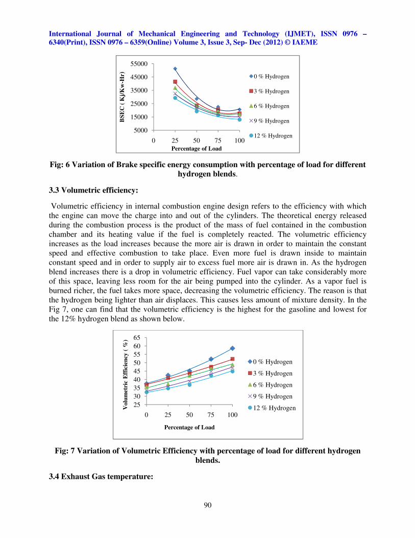
3.1 Brake thermal efficiency:
The Brake thermal efficiency increases as the load increases. The mass flow rate increases as the
load increases to maintain the constant speed. The fuel gets utilized properly for combustion at
higher loads due to increase in brake power. As the hydrogen blend increases, the hydrogen has a
much higher diffusion speed than pure gasoline, and reduced combustion period causes the
increase in the specific heat ratio during expansion stroke which increases the brake thermal
efficiency. If there is not enough oxygen for proper combustion, the fuel will not burn
completely and will produce less energy. As due to increase in hydrogen blending there will be
good fuel conversion efficiency which reduces the partial burning. One can observe that the
brake thermal efficiency for the 12% hydrogen is the highest and least for the gasoline as shown
in Fig 5 as shown below.
Fig: 5 Variation of brake thermal efficiency with percentage of load for different hydrogen
blends
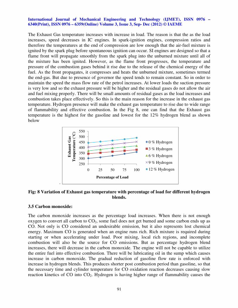
3.2 Brake specific energy consumption:
The brake specific energy consumption decreases as the load increases. Due to the brake power
developed higher at higher loads, the consumption of fuel per kilowatt hour reduces. The main
reason is that the combustion takes place effectively. Brake specific energy consumption (BSEC)
is a measure of the efficiency of an internal combustion engine. The term specific energy
consumption refers to the amount of energy fuel used normalized to the amount of power
generated, which gives an efficiency at certain operating point of the engine. The effective
combustion is due to the proper mixing of air and fuel at constant speed and also due to which
also lead in rise of cylinder pressure. This is also due to narrow range of flammability of oxygen
and causes the more fuel to draw in leading to more specific fuel consumption. One can observe
that the brake specific energy consumption for gasoline is highest for gasoline and lowest for
12% of hydrogen blend as shown in Fig 6 below.
0
5
10
15
20
25
0 25 50 75 100Bra
ke
Th
erm
al
Eff
icie
ncy
( %
)
Percentage of Load
0 % Hydrogen
3% Hydrogen
6 % Hydrogen
9 % Hydrogen
12 % Hydrogen
International Journal of Mechanical Engineering and Technology (IJMET), ISSN 0976 –
6340(Print), ISSN 0976 – 6359(Online) Volume 3, Issue 3, Sep- Dec (2012) © IAEME
90
Fig: 6 Variation of Brake specific energy consumption with percentage of load for different
hydrogen blends.
3.3 Volumetric efficiency:
Volumetric efficiency in internal combustion engine design refers to the efficiency with which
the engine can move the charge into and out of the cylinders. The theoretical energy released
during the combustion process is the product of the mass of fuel contained in the combustion
chamber and its heating value if the fuel is completely reacted. The volumetric efficiency
increases as the load increases because the more air is drawn in order to maintain the constant
speed and effective combustion to take place. Even more fuel is drawn inside to maintain
constant speed and in order to supply air to excess fuel more air is drawn in. As the hydrogen
blend increases there is a drop in volumetric efficiency. Fuel vapor can take considerably more
of this space, leaving less room for the air being pumped into the cylinder. As a vapor fuel is
burned richer, the fuel takes more space, decreasing the volumetric efficiency. The reason is that
the hydrogen being lighter than air displaces. This causes less amount of mixture density. In the
Fig 7, one can find that the volumetric efficiency is the highest for the gasoline and lowest for
the 12% hydrogen blend as shown below.
Fig: 7 Variation of Volumetric Efficiency with percentage of load for different hydrogen
blends.
3.4 Exhaust Gas temperature:
5000
15000
25000
35000
45000
55000
0 25 50 75 100
BS
EC
( K
j/K
w-H
r)
Percentage of Load
0 % Hydrogen
3 % Hydrogen
6 % Hydrogen
9 % Hydrogen
12 % Hydrogen
25
30
35
40
45
50
55
60
65
0 25 50 75 100
Volu
met
ric
Eff
icie
ncy
( %
)
Percentage of Load
0 % Hydrogen
3 % Hydrogen
6 % Hydrogen
9 % Hydrogen
12 % Hydrogen
International Journal of Mechanical Engineering and Technology (IJMET), ISSN 0976 –
6340(Print), ISSN 0976 – 6359(Online) Volume 3, Issue 3, Sep- Dec (2012) © IAEME
91
The Exhaust Gas temperature increases with increase in load. The reason is that the as the load
increases, speed decreases in IC engines. In spark-ignition engines, compression ratios and
therefore the temperatures at the end of compression are low enough that the air-fuel mixture is
ignited by the spark plug before spontaneous ignition can occur. SI engines are designed so that a
flame front will propagate smoothly from the spark plug into the unburned mixture until all of
the mixture has been ignited. However, as the flame front progresses, the temperature and
pressure of the combustion gases behind it rise due to the release of the chemical energy of the
fuel. As the front propagates, it compresses and heats the unburned mixture, sometimes termed
the end-gas. But due to presence of governor the speed tends to remain constant. So in order to
maintain the speed the mass flow rate of the petrol increases. At lower loads the suction pressure
is very low and so the exhaust pressure will be higher and the residual gases do not allow the air
and fuel mixing properly. There will be small amounts of residual gases as the load increases and
combustion takes place effectively. So this is the main reason for the increase in the exhaust gas
temperature. Hydrogen presence will make the exhaust gas temperature to rise due to wide range
of flammability and effective combustion. In the Fig 8, one can find that the Exhaust gas
temperature is the highest for the gasoline and lowest for the 12% hydrogen blend as shown
below
.
Fig: 8 Variation of Exhaust gas temperature with percentage of load for different hydrogen
blends.
3.5 Carbon monoxide:
The carbon monoxide increases as the percentage load increases. When there is not enough
oxygen to convert all carbon to CO2, some fuel does not get burned and some carbon ends up as
CO. Not only is CO considered an undesirable emission, but it also represents lost chemical
energy. Maximum CO is generated when an engine runs rich. Rich mixture is required during
starting or when accelerating under load. Poor mixing, local rich regions, and incomplete
combustion will also be the source for CO emissions. But as percentage hydrogen blend
increases, there will decrease in the carbon monoxide. The engine will not be capable to utilize
the entire fuel into effective combustion. There will be lubricating oil in the sump which causes
increase in carbon monoxide. The gradual reduction of gasoline flow rate is enforced with
increase in hydrogen blends. This produces shorter post combustion period than gasoline, so that
the necessary time and cylinder temperature for CO oxidation reaction decreases causing slow
reaction kinetics of CO into CO2. Hydrogen is having higher range of flammability causes the
250
300
350
400
450
500
550
0 25 50 75 100
Exh
au
st G
as
Tem
per
atu
re (
°C)
Percentage of Load
0 % Hydrogen
3 % Hydrogen
6 % Hydrogen
9 % Hydrogen
12 % Hydrogen
International Journal of Mechanical Engineering and Technology (IJMET), ISSN 0976 –
6340(Print), ISSN 0976 – 6359(Online) Volume 3, Issue 3, Sep- Dec (2012) © IAEME
92
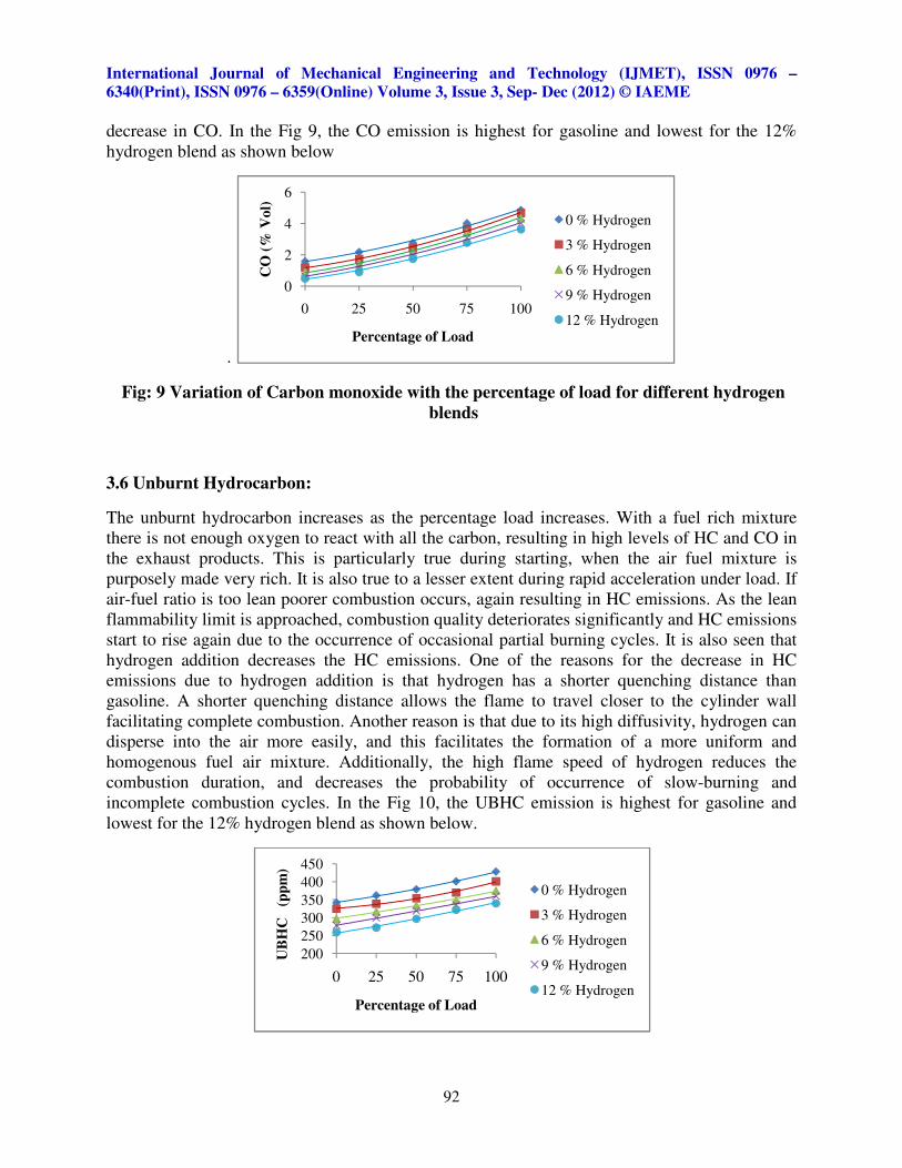
decrease in CO. In the Fig 9, the CO emission is highest for gasoline and lowest for the 12%
hydrogen blend as shown below
.
Fig: 9 Variation of Carbon monoxide with the percentage of load for different hydrogen
blends
3.6 Unburnt Hydrocarbon:
The unburnt hydrocarbon increases as the percentage load increases. With a fuel rich mixture
there is not enough oxygen to react with all the carbon, resulting in high levels of HC and CO in
the exhaust products. This is particularly true during starting, when the air fuel mixture is
purposely made very rich. It is also true to a lesser extent during rapid acceleration under load. If
air-fuel ratio is too lean poorer combustion occurs, again resulting in HC emissions. As the lean
flammability limit is approached, combustion quality deteriorates significantly and HC emissions
start to rise again due to the occurrence of occasional partial burning cycles. It is also seen that
hydrogen addition decreases the HC emissions. One of the reasons for the decrease in HC
emissions due to hydrogen addition is that hydrogen has a shorter quenching distance than
gasoline. A shorter quenching distance allows the flame to travel closer to the cylinder wall
facilitating complete combustion. Another reason is that due to its high diffusivity, hydrogen can
disperse into the air more easily, and this facilitates the formation of a more uniform and
homogenous fuel air mixture. Additionally, the high flame speed of hydrogen reduces the
combustion duration, and decreases the probability of occurrence of slow-burning and
incomplete combustion cycles. In the Fig 10, the UBHC emission is highest for gasoline and
lowest for the 12% hydrogen blend as shown below.
0
2
4
6
0 25 50 75 100
CO
(%
Vo
l)
Percentage of Load
0 % Hydrogen
3 % Hydrogen
6 % Hydrogen
9 % Hydrogen
12 % Hydrogen
200
250
300
350
400
450
0 25 50 75 100
UB
HC
(
pp
m)
Percentage of Load
0 % Hydrogen
3 % Hydrogen
6 % Hydrogen
9 % Hydrogen
12 % Hydrogen
International Journal of Mechanical Engineering and Technology (IJMET), ISSN 0976 –
6340(Print), ISSN 0976 – 6359(Online) Volume 3, Issue 3, Sep- Dec (2012) © IAEME
93
Fig: 10Variation of UBHC with the percentage of load for different hydrogen blends.
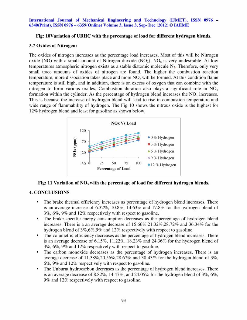
3.7 Oxides of Nitrogen:
The oxides of nitrogen increases as the percentage load increases. Most of this will be Nitrogen
oxide (NO) with a small amount of Nitrogen dioxide (NO2). NOx is very undesirable. At low
temperatures atmospheric nitrogen exists as a stable diatomic molecule N2. Therefore, only very
small trace amounts of oxides of nitrogen are found. The higher the combustion reaction
temperature, more dissociation takes place and more NOx will be formed. At this condition flame
temperature is still high, and in addition, there is an excess of oxygen that can combine with the
nitrogen to form various oxides. Combustion duration also plays a significant role in NOx
formation within the cylinder. As the percentage of hydrogen blend increases the NOx increases.
This is because the increase of hydrogen blend will lead to rise in combustion temperature and
wide range of flammability of hydrogen. The Fig 10 shows the nitrous oxide is the highest for
12% hydrogen blend and least for gasoline as shown below.
Fig: 11 Variation of NOx with the percentage of load for different hydrogen blends.
4. CONCLUSIONS
� The brake thermal efficiency increases as percentage of hydrogen blend increases. There
is an average increase of 6.32%, 10.8%, 14.63% and 17.8% for the hydrogen blend of
3%, 6%, 9% and 12% respectively with respect to gasoline.
� The brake specific energy consumption decreases as the percentage of hydrogen blend
increases. There is a an average decrease of 15.66%,21.32%,28.72% and 36.34% for the
hydrogen blend of 3%,6%,9% and 12% respectively with respect to gasoline.
� The volumetric efficiency decreases as the percentage of hydrogen blend increases. There
is an average decrease of 6.15%, 11.22%, 18.23% and 24.36% for the hydrogen blend of
3%, 6%, 9% and 12% respectively with respect to gasoline.
� The carbon monoxide decreases as the percentage of hydrogen increases. There is an
average decrease of 11.38%,20.56%,28.67% and 38 43% for the hydrogen blend of 3%,
6%, 9% and 12% respectively with respect to gasoline.
� The Unburnt hydrocarbon decreases as the percentage of hydrogen blend increases. There
is an average decrease of 8.82%, 14.47%, and 24.05% for the hydrogen blend of 3%, 6%,
9% and 12% respectively with respect to gasoline.
-30
20
70
120
0 25 50 75 100
NO
x (
pp
m)
Percentage of Load
NOx Vs Load
0 % Hydrogen
3 % Hydrogen
6 % Hydrogen
9 % Hydrogen
12 % Hydrogen
International Journal of Mechanical Engineering and Technology (IJMET), ISSN 0976 –
6340(Print), ISSN 0976 – 6359(Online) Volume 3, Issue 3, Sep- Dec (2012) © IAEME
94
� The NOx increases as the percentage of hydrogen blend increases. There is an average
increase of 17.92%, 32.56%, 50.61% and 61.2% for the hydrogen blend of 3%, 6%, 9%
and 12% respectively with respect to gasoline.
� From the experiment that was conducted, one can conclude that the engine goes towards
lean mixture. This is because of higher flammability of hydrogen and higher diffusion
speed.
ACKNOWLEDGEMENT
Authors whole heartedly thank the NITK Surathkal institution for providing financial support.
REFERENCES
[1] Erol Kahramana, S. Cihangir Ozcanlıb, Baris Ozerdemb (2007), “An experimental study on
performance and emission characteristics of a hydrogen fuelled spark ignition engine”,
International Journal of Hydrogen Energy, vol. 32, P 2066 – 2072.
[2] Changwei Ji, Shuofeng Wang (2009),” Effect of hydrogen addition on combustion and
emissions performance of a spark ignition gasoline engine at lean conditions”, International
journal of Hydrogen Energy, vol. 34, P 823-7834.
[3] Farhad Salimi, Amir H. Shamokin, Ali M. Pourkhesalian (2009),” Role of mixture richness,
spark and valve timing in hydrogen-fuelled engine performance and emission” International
Journal of Hydrogen Energy, vol. 34, P 3922-3929.
[4] Shuofeng Wang, Changwei Ji, Bo Zhang (2011), “Starting a spark-ignited engine with the
gasoline hydrogen mixture”, International Journal of Hydrogen Energy, vol. 36, P 4461-
4468.
[5] James W. Hewel (2003),” NOx emission and performance data for a hydrogen fueled internal
combustion engine at 1500 rpm using exhaust gas recirculation”, International Journal of
Hydrogen Energy, vol. 28,P 901-908.
[6] Changwei Ji, Shuofeng Wang (2010),” Combustion and emissions performance of a hybrid
hydrogen–gasoline engine at idle and lean conditions”, International Journal of Hydrogen
Energy, vol. 35, P 346-355.
[7] C.M. White, R.R. Steeper, A.E. Lutz (2006), “The hydrogen-fueled internal combustion
engine: a technical review”, International Journal of Hydrogen Energy, vol. 31, P 1292-1305.
[8] Ghazi A. Karim (2003), “Hydrogen as a spark ignition engine fuel” International of
Hydrogen Energy, vol. 28, P 569-577.

International Journal of Mechanical Engineering and Technology (IJMET), ISSN 0976 –
6340(Print), ISSN 0976 – 6359(Online) Volume 3, Issue 3, Sep- Dec (2012) © IAEME
95
AUTHORS
Suhas B.G received his B.E degree from PESIT, Bangalore under VTU
university. Now he is pursuing M Tech degree in Thermal Engineering from
NITK, Surathkal. His research interest is IC engines.
Shivaprasad K.V received his B.E degree from Malnad college of
engineering, Hassan under VTU university, M Tech degree in Energy
System Engineering from NITTE, Karkala under VTU university. Now he is
pursuing Ph.D degree in NITK, Surathkal. His research interests are
Renewable energy and IC engines.
Kumar G.N received his M Tech degree in Heat Power Engineering at
NITK, Surathkal and Ph.D degree from Indian Institute of Technology,
Delhi. He is currently working as Assistant Professor at NITK, Surathkal. He
has served as an organizer for several National and International conference.
His research interests are IC engines, Renewable energy and Heat transfer.