Embed Size (px)
Citation preview

INS
TRU
CTIO
NM
AN
UA
L8 1/4"
Compound Miter Saw(Model 36-040)
PART NO. 899852 (012)Copyright © 2001 Delta Machinery
ESPAÑOL: PÁGINA 17To learn more about DELTA MACHINERY visit our website at: www.deltamachinery.com.For Parts, Service, Warranty or other Assistance,
please call 1-800-223-7278 (In Canada call 1-800-463-3582).

2
SAFETY RULESWoodworking can be dangerous if safe and proper operating procedures are not followed. As with all machinery, thereare certain hazards involved with the operation of the product. Using the machine with respect and caution will con-siderably lessen the possibility of personal injury. However, if normal safety precautions are overlooked or ignored, per-sonal injury to the operator may result. Safety equipment such as guards, push sticks, hold-downs, featherboards,goggles, dust masks and hearing protection can reduce your potential for injury. But even the best guard won’t makeup for poor judgment, carelessness or inattention. Always use common sense and exercise caution in the workshop.If a procedure feels dangerous, don’t try it. Figure out an alternative procedure that feels safer. REMEMBER: Yourpersonal safety is your responsibility.
This machine was designed for certain applications only. Delta Machinery strongly recommends that this machine notbe modified and/or used for any application other than that for which it was designed. If you have any questions rela-tive to a particular application, DO NOT use the machine until you have first contacted Delta to determine if it can orshould be performed on the product.
Technical Service ManagerDelta Machinery4825 Highway 45 NorthJackson, TN 38305
(IN CANADA: 505 SOUTHGATE DRIVE, GUELPH, ONTARIO N1H 6M7)
WARNING: FAILURE TO FOLLOW THESE RULES MAY RESULT IN SERIOUS PERSONAL INJURY
1. FOR YOUR OWN SAFETY, READ INSTRUCTIONMANUAL BEFORE OPERATING THE TOOL. Learn thetool’s application and limitations as well as the specific haz-ards peculiar to it.
2. KEEP GUARDS IN PLACE and in working order.3. ALWAYS WEAR EYE PROTECTION.4. REMOVE ADJUSTING KEYS AND WRENCHES.
Form habit of checking to see that keys and adjustingwrenches are removed from tool before turning it “on”.5. KEEP WORK AREA CLEAN. Cluttered areas and
benches invite accidents.6. DON’T USE IN DANGEROUS ENVIRONMENT. Don’t
use power tools in damp or wet locations, or expose themto rain. Keep work area well-lighted.
7. KEEP CHILDREN AND VISITORS AWAY. All childrenand visitors should be kept a safe distance from work area.
8. MAKE WORKSHOP CHILDPROOF – with padlocks,master switches, or by removing starter keys.
9. DON’T FORCE TOOL. It will do the job better and besafer at the rate for which it was designed.10. USE RIGHT TOOL. Don’t force tool or attachment todo a job for which it was not designed.11. WEAR PROPER APPAREL. No loose clothing, gloves,neckties, rings, bracelets, or other jewelry to get caught inmoving parts. Nonslip footwear is recommended. Wearprotective hair covering to contain long hair.12. ALWAYS USE SAFETY GLASSES. Wear safety glass-es. Everyday eyeglasses only have impact resistant lens-es; they are not safety glasses. Also use face or dustmask if cutting operation is dusty. These safety glassesmust conform to ANSI Z87.1 requirements. Note:Approved glasses have Z87 printed or stamped onthem.13. SECURE WORK. Use clamps or a vise to hold workwhen practical. It’s safer than using your hand and freesboth hands to operate tool.14. DON’T OVERREACH. Keep proper footing and bal-ance at all times.15. MAINTAIN TOOLS IN TOP CONDITION. Keep toolssharp and clean for best and safest performance. Followinstructions for lubricating and changing accessories.16. DISCONNECT TOOLS before servicing and whenchanging accessories such as blades, bits, cutters, etc.17. USE RECOMMENDED ACCESSORIES. The use ofaccessories and attachments not recommended by Deltamay cause hazards or risk of injury to persons.
18. REDUCE THE RISK OF UNINTENTIONAL START-ING. Make sure switch is in “OFF” position before pluggingin power cord.19. NEVER STAND ON TOOL. Serious injury could occurif the tool is tipped or if the cutting tool is accidentally con-tacted.20. CHECK DAMAGED PARTS. Before further use of thetool, a guard or other part that is damaged should be care-fully checked to ensure that it will operate properly and per-form its intended function – check for alignment of movingparts, binding of moving parts, breakage of parts, mount-ing, and any other conditions that may affect its operation.A guard or other part that is damaged should be properlyrepaired or replaced.21. DIRECTION OF FEED. Feed work into a blade or cut-ter against the direction of rotation of the blade or cutteronly.22. NEVER LEAVE TOOL RUNNING UNATTENDED.TURN POWER OFF. Don’t leave tool until it comes to acomplete stop.23. DRUGS, ALCOHOL, MEDICATION. Do not operatetool while under the influence of drugs, alcohol or any med-ication.24. MAKE SURE TOOL IS DISCONNECTED FROMPOWER SUPPLY while motor is being mounted, connect-ed or re-connected.25. THE DUST GENERATED by certain woods and woodproducts can be injurious to your health. Always operatemachinery in well ventilated areas and provide for properdust removal. Use wood dust collection systems wheneverpossible.26. WARNING: SOME DUST CREATED BYPOWER SANDING, SAWING, GRINDING, DRILLING,AND OTHER CONSTRUCTION ACTIVITIES containschemicals known to cause cancer, birth defects or otherreproductive harm. Some examples of these chemicalsare:· lead from lead-based paints,· crystalline silica from bricks and cement and other
masonry products, and· arsenic and chromium from chemically-treated lumber. Your risk from these exposures varies, depending onhow often you do this type of work. To reduce yourexposure to these chemicals: work in a well ventilatedarea, and work with approved safety equipment, such asthose dust masks that are specially designed to filter outmicroscopic particles.
SAVE THESE INSTRUCTIONS
33
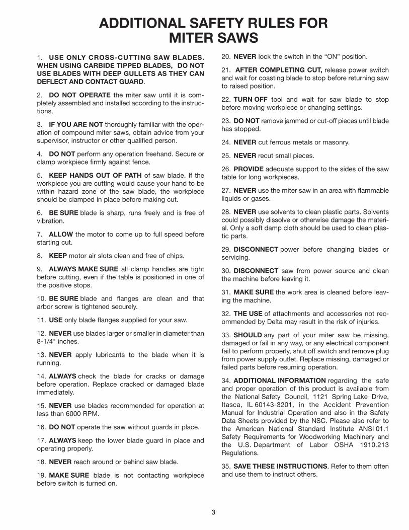
ADDITIONAL SAFETY RULES FORMITER SAWS
1. USE ONLY CROSS-CUTTING SAW BLADES.WHEN USING CARBIDE TIPPED BLADES, DO NOTUSE BLADES WITH DEEP GULLETS AS THEY CANDEFLECT AND CONTACT GUARD.
2. DO NOT OPERATE the miter saw until it is com-pletely assembled and installed according to the instruc-tions.
3. IF YOU ARE NOT thoroughly familiar with the oper-ation of compound miter saws, obtain advice from yoursupervisor, instructor or other qualified person.
4. DO NOT perform any operation freehand. Secure orclamp workpiece firmly against fence.
5. KEEP HANDS OUT OF PATH of saw blade. If theworkpiece you are cutting would cause your hand to bewithin hazard zone of the saw blade, the workpieceshould be clamped in place before making cut.
6. BE SURE blade is sharp, runs freely and is free ofvibration.
7. ALLOW the motor to come up to full speed beforestarting cut.
8. KEEP motor air slots clean and free of chips.
9. ALWAYS MAKE SURE all clamp handles are tightbefore cutting, even if the table is positioned in one ofthe positive stops.
10. BE SURE blade and flanges are clean and thatarbor screw is tightened securely.
11. USE only blade flanges supplied for your saw.
12. NEVER use blades larger or smaller in diameter than8-1/4" inches.
13. NEVER apply lubricants to the blade when it isrunning.
14. ALWAYS check the blade for cracks or damagebefore operation. Replace cracked or damaged bladeimmediately.
15. NEVER use blades recommended for operation atless than 6000 RPM.
16. DO NOT operate the saw without guards in place.
17. ALWAYS keep the lower blade guard in place andoperating properly.
18. NEVER reach around or behind saw blade.
19. MAKE SURE blade is not contacting workpiecebefore switch is turned on.
20. NEVER lock the switch in the “ON” position.
21. AFTER COMPLETING CUT, release power switchand wait for coasting blade to stop before returning sawto raised position.
22. TURN OFF tool and wait for saw blade to stopbefore moving workpiece or changing settings.
23. DO NOT remove jammed or cut-off pieces until bladehas stopped.
24. NEVER cut ferrous metals or masonry.
25. NEVER recut small pieces.
26. PROVIDE adequate support to the sides of the sawtable for long workpieces.
27. NEVER use the miter saw in an area with flammableliquids or gases.
28. NEVER use solvents to clean plastic parts. Solventscould possibly dissolve or otherwise damage the materi-al. Only a soft damp cloth should be used to clean plas-tic parts.
29. DISCONNECT power before changing blades orservicing.
30. DISCONNECT saw from power source and cleanthe machine before leaving it.
31. MAKE SURE the work area is cleaned before leav-ing the machine.
32. THE USE of attachments and accessories not rec-ommended by Delta may result in the risk of injuries.
33. SHOULD any part of your miter saw be missing,damaged or fail in any way, or any electrical componentfail to perform properly, shut off switch and remove plugfrom power supply outlet. Replace missing, damaged orfailed parts before resuming operation.
34. ADDITIONAL INFORMATION regarding the safeand proper operation of this product is available fromthe National Safety Council, 1121 Spring Lake Drive,Itasca, IL 60143-3201, in the Accident PreventionManual for Industrial Operation and also in the SafetyData Sheets provided by the NSC. Please also refer tothe American National Standard Institute ANSI 01.1Safety Requirements for Woodworking Machinery andthe U.S. Department of Labor OSHA 1910.213Regulations.
35. SAVE THESE INSTRUCTIONS. Refer to them oftenand use them to instruct others.

4
UNPACKINGYour new Miter Saw is shipped complete in one con-tainer. Carefully unpack the saw and all loose itemsfrom the shipping container. Fig. 2, illustrates the con-tents of the container:
A - Miter SawB - Lower Guard AssemblyC - Dust Bag* - Extra Switch Lock Key
(Not Shown)
Fig. 2
ASSEMBLY INSTRUCTIONSWARNING: FOR YOUR OWN SAFETY, DO NOT CONNECT THE MITER SAW TO THE POWER SOURCEUNTIL THE MACHINE IS COMPLETELY ASSEMBLED AND YOU HAVE READ AND UNDERSTOOD THEENTIRE OWNER’S MANUAL.
MOVING CUTTING ARM TO THE UP POSITION1. Pull pin (A) Fig. 3, to the out position releasing the cutting arm (B) and allow cutting arm (B) to move to the up posi-tion, as shown in Fig. 4.
Fig. 3 Fig. 4
ASSEMBLING LOWER BLADE GUARD1. Hook one end of guard lifting lever (A) Fig. 5, on stud (B), as shown.2. Loosen screw (D) Fig. 6, and remove screw (C)
Fig. 5 Fig. 6
A
C
B
A
B
A
B
D
C
B
5
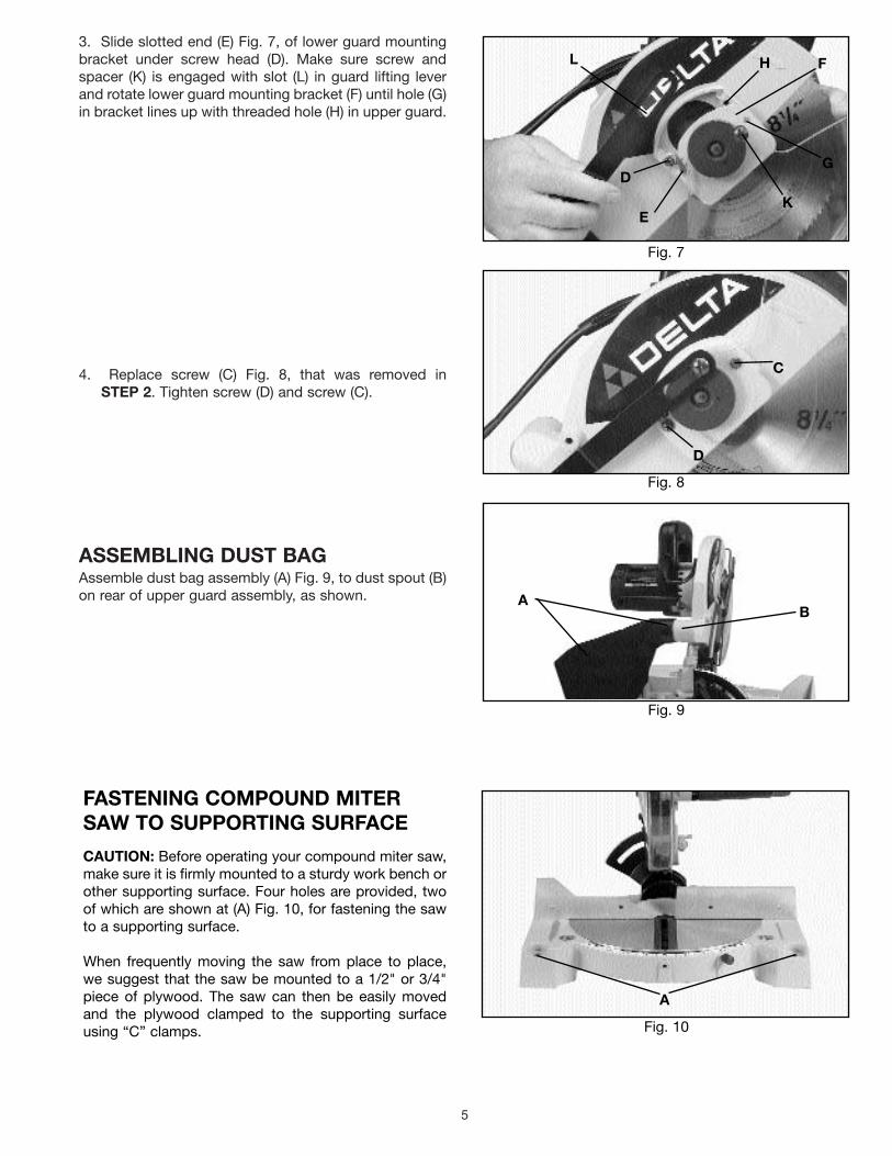
3. Slide slotted end (E) Fig. 7, of lower guard mountingbracket under screw head (D). Make sure screw andspacer (K) is engaged with slot (L) in guard lifting leverand rotate lower guard mounting bracket (F) until hole (G)in bracket lines up with threaded hole (H) in upper guard.
4. Replace screw (C) Fig. 8, that was removed in STEP 2. Tighten screw (D) and screw (C).
ASSEMBLING DUST BAGAssemble dust bag assembly (A) Fig. 9, to dust spout (B)on rear of upper guard assembly, as shown.
FASTENING COMPOUND MITERSAW TO SUPPORTING SURFACE
CAUTION: Before operating your compound miter saw,make sure it is firmly mounted to a sturdy work bench orother supporting surface. Four holes are provided, twoof which are shown at (A) Fig. 10, for fastening the sawto a supporting surface.
When frequently moving the saw from place to place,we suggest that the saw be mounted to a 1/2" or 3/4"piece of plywood. The saw can then be easily movedand the plywood clamped to the supporting surfaceusing “C” clamps. Fig. 10
Fig. 9
Fig. 8
Fig. 7
L H F
G
K
D
E
C
D
BA
A
6
CONNECTING SAW TO POWER SOURCEPOWER CONNECTIONS
A separate electrical circuit should be used for your tools. This circuit should not be less than #12 wire and should beprotected with a 20 Amp time lag fuse. Before connecting the motor to the power line, make sure the switch is in the“OFF” position and be sure that the electric current is of the same characteristics as indicated on the tool. All line con-nections should make good contact. Running on low voltage will damage the motor.
MOTOR SPECIFICATIONSYour miter saw is wired for 110-120 volt, 60 HZ alternating current. Before connecting the miter saw to the powersource, make sure the switch is in the “OFF” position. The motor provides a no-load speed of 5200 RPM.
DOUBLE-INSULATED TOOLS
REPLACEMENT PARTSWhen servicing, use only identical replacement parts.
POLARIZED PLUGS
To reduce the risk of electric shock, this equipment has a polarized plug one blade is wider than the other). This plugwill fit in a polarized outlet only one way. If the plug does not fit fully in the outlet, reverse the plug. If it still does not fit,contact a qualified electrician to install the proper outlet. Do not change the plug in any way.

7
Use proper extension cords. Make sure your extensioncord is in good condition. When using an extensioncord, be sure to use one heavy enough to carry the cur-rent of the saw. An undersized cord will cause a drop inline voltage, resulting in loss of power and overheating.Fig. 11B, shows the correct gauge to use depending onthe cord length. If in doubt, use the next heavier gauge.The smaller the gauge number, the heavier the cord.
Fig. 11B
EXTENSION CORDS
OPERATING INSTRUCTIONSFOREWORDDelta Model 36-040 is a 81¼4" compound miter saw designed to cut wood. Compound angle and bevel cutting is easyand accurate. It can crosscut up to 21¼8" x 51¼8", miter at 45° both left and right 21¼8" x 31¼2", bevel at 45° left 11¼2" x 51¼8", and compound 45° x 45°, 11¼2" x 31¼2". It has positive miter ball detent stops at 0, 15, 22.5, 30, and 45 degreesboth left and right, and bevel stops at 0 and 45 degrees left.
UNPACKING AND CLEANINGCarefully unpack the tool and all loose items from the shipping container(s). Remove the protective coating from allunpainted surfaces. This coating may be removed with a soft cloth moistened with kerosene (do not use acetone, gaso-line or lacquer thinner for this purpose). After cleaning, cover the unpainted sufaces with a good quality paste wax.
MINIMUM GAUGE EXTENSION CORDRECOMMENDED SIZES FOR USE WITH STATIONARY ELECTRIC TOOLS
Ampere Volts Total Length of Gauge ofRating Cord in Feet Extension Cord0-6 120 up to 25 18 AWG0-6 120 25-50 16 AWG0-6 120 50-100 16 AWG0-6 120 100-150 14 AWG6-10 120 up to 25 18 AWG6-10 120 25-50 16 AWG6-10 120 50-100 14 AWG6-10 120 100-150 12 AWG 10-12 120 up to 25 16 AWG10-12 120 25-50 16 AWG10-12 120 50-100 14 AWG10-12 120 100-150 12 AWG12-16 120 up to 25 14 AWG12-16 120 25-50 12 AWG 12-16 120 GREATER THAN 50 FEET NOT RECOMMENDED

8
OPERATING CONTROLS
LOCKING SWITCH IN THE “OFF” POSITIONIMPORTANT: When the saw is not in use, the switchmust be locked in the “OFF” position.
WARNING: MAKE CERTAIN THE MACHINE ISDISCONNECTED FROM THE POWER SOURCEBEFORE REMOVING AND REASSEMBLING SWITCHLOCK KEY.To lock the switch (B) Fig. 12, in the “OFF” position, pullor gently pry out and remove switch lock key (A) fromsaw handle.To activate the switch (B) Fig. 12, insert switch lock key(A) firmly back into handle.
ROTATING TABLE FOR MITER CUTTINGYour compound miter saw will cut any miter angle froma straight 90 degree cut-off to 45 degrees right and left.Simply loosen table lock knob (A) Fig. 13, and using theswitch handle as a grip, rotate the cutting arm until thepointer (B) aligns with the desired setting on the miterscale (C). Then tighten table lock knob (A).
WARNING: LOCK KNOB (A) MUST BE TIGHT-ENED FOR ALL CUTTING OPERATIONS.
Your compound miter saw contains positive stops forthe table at the 0, 22-1/2, 30 and 45 degree right and leftpositions. Two triangle indicators (D) Fig. 14, are alsoprovided to rapidly set the table at the 31-5/8 degreeright and left miter angle for cutting crown moulding, asexplained later in this manual.
TILTING CUTTING ARM FOR BEVEL CUTTING
Loosen bevel cutting lock handle (A) Fig. 15, tilt cuttingarm to the desired bevel angle and tighten lock handle(A). NOTE: Lock handle (A) is spring-loaded and can bere-positioned by pulling out on the handle and reposi-tioning it on the serrated stud located underneath thehandle.
WARNING: LOCK HANDLE (A) MUST BE TIGHT-ENED DURING ALL CUTTING OPERATIONS.
The bevel angle of the cutting arm is determined by theposition of the pointer (B) Fig. 15, on the large scale (C).A triangle indicator (D) is provided to rapidly position thecutting arm at the 33-7/8 degree left bevel angle whichis used for cutting crown moulding, as explained later inthis manual.
Fig. 12
STARTING AND STOPPING SAWIMPORTANT: Before starting the saw, lower the cutting arm and make certain the saw blade does not come in contactwith the front edge or rear edge of the table insert on its full downward travel. The downward travel of the cutting armhas been set at the factory; however, sometimes due to rough handling during shipment or extended use, a minoradjustment to the setting may become necessary. If the saw blade contacts the table insert, refer to section “ADJUST-ING DOWNWARD TRAVEL OF SAW BLADE.”To turn the saw “ON” push in on switch lock key (A) Fig. 12, and depress switch trigger (B). To turn the saw “OFF”release switch trigger (B).
Fig. 13
Fig. 14
Fig. 15
DD
A
D
B
C
B
AC
A
B

9
LOCKING CUTTING ARM IN THE DOWN POSITIONWhen transporting the miter saw, the cutting arm shouldalways be locked in the down position. This can beaccomplished by lowering the cutting arm and pushingin on arm locking pin (A) Fig. 16.
ADJUSTMENTSADJUSTING DOWNWARD TRAVEL OF SAW BLADE ARMLower the saw blade arm as far as it will go and checkto see if the saw blade comes in contact with the tableinsert. If the saw blade (A) Fig. 17, contacts the frontedge or the rear edge of table insert (B) on its downwardtravel, proceed with the following adjustment.1. MAKE CERTAIN THE MACHINE IS DISCONNECT-ED FROM THE POWER SOURCE.2. Loosen lock nut (C) Fig. 18, and turn adjustment knob(D) right or left.3. Lower the saw blade arm and check the adjustment.NOTE: There should be a slight clearance between thesaw blade (A) Fig. 17, and table insert (B) as shown.Repeat STEP 2, if necessary.4. Tighten lock nut (C) Fig 18, after adjustment is made.
ADJUSTING FENCE 90 DEGREES TO BLADE1. DISCONNECT THE MACHINE FROM THE POWERSOURCE.
2. Place the cutting arm in the 90 degree straight cut-offposition, as shown in Fig. 19, and tighten the table lockknob (A).
3. Lower the saw blade, as shown in Fig. 19.
4. Using a square (B) Fig. 19, place one end of thesquare against the fence and the other end against theblade, as shown.
5. Check to see if the blade is at 90 degrees to the fence.
6. If an adjustment is necessary, loosen the two screws(C) Fig. 20, and adjust the fence until it is 90 degrees tothe blade. Then tighten two screws (C).
Fig. 16
Fig. 17
Fig. 18
Fig. 19 Fig. 20
A
B
A
D C
AB
CC

10
ADJUSTING 90 AND 45 DEGREE BEVEL STOPS
1. DISCONNECT THE MACHINE FROM THE POWERSOURCE.
2. Move the cutting arm to the 90 degree bevel stopposition, as shown in Fig. 21, and tighten the bevel lockhandle.
3. Using a square (A) Fig. 21, place one end of thesquare on the table and the other end against the blade.Check to see if the blade is at 90 degrees to the table,as shown.
4. If an adjustment is necessary, loosen bevel lock han-dle (B) Fig. 22, and tilt cutting arm until the blade is at 90degrees to the table. NOTE: It may be necessary toloosen locknut (C) and set screw (D) to accomplish this.Then tighten bevel lock handle (B).
5. Loosen nut (C) Fig. 22, and tighten set screw (D) untilit bottoms. Then tighten locknut (C).
6. Tilt the cutting arm all the way to the left miter posi-tion and tighten the bevel lock handle.
7. Using a combination square (A) Fig. 23, check to seeif the blade is at 45 degrees to the table, as shown.
8. If an adjustment is necessary, loosen bevel lock han-dle (B) Fig. 24, and tilt the cutting arm until the blade isat 45 degrees to the table. NOTE: It may be necessaryto loosen locknut (E) and set screw (F) to accomplishthis. Then tighten bevel lock handle (B).
9. Loosen locknut (E) Fig. 24, and tighten set screw (F)until it bottoms. Then tighten locknut (E).
10. These positive stops enable you to rapidly positionthe blade at the 90 and 45 degree bevel positions.
Fig. 21
Fig. 22
A
B
C
Fig. 23
A
Fig. 24
B
E F
D

11
ADJUSTING SPRING PRESSURE OFTABLE POSITIVE STOPThe rotating table has positive stops at the 90 degreestraight cut-off position and 22-1/2, 30 and 45 degreeright and left miter positions. To adjust the spring pres-sure of the positive stops, tighten or loosen screw (A) Fig.25. NOTE: Do not tighten screw (A) to the point where itbecomes difficult to rotate the table.
Fig. 25
OPERATING HINTS1. Before cutting, make certain the miter and bevel angles are set and firmly locked in place.2. Before cutting, determine that the workpiece is the right size for the saw.3. Place the workpiece on the table and hold it firmly against the fence.4. For best results, cut at a slow, even cutting rate.5. WARNING: Keep hands out of path of saw blade. If the workpiece you are cutting would cause your
hand to be within hazard zone of the saw blade, the workpiece should be clamped in place before making cut.
6. Never attempt any freehand cutting (wood that is not held firmly against the fence and table).
A
12
MAINTENANCECHANGING THE BLADE
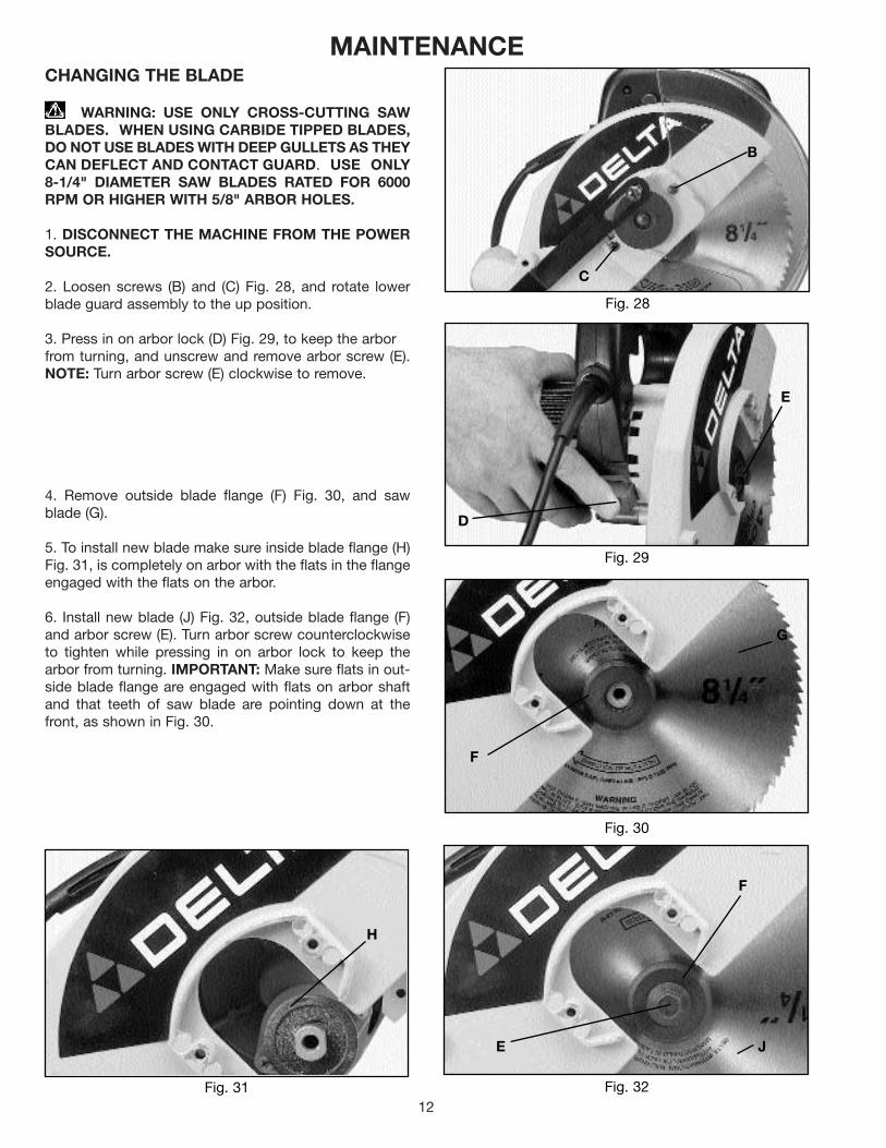
WARNING: USE ONLY CROSS-CUTTING SAWBLADES. WHEN USING CARBIDE TIPPED BLADES,DO NOT USE BLADES WITH DEEP GULLETS AS THEYCAN DEFLECT AND CONTACT GUARD. USE ONLY 8-1/4" DIAMETER SAW BLADES RATED FOR 6000RPM OR HIGHER WITH 5/8" ARBOR HOLES.
1. DISCONNECT THE MACHINE FROM THE POWERSOURCE.
2. Loosen screws (B) and (C) Fig. 28, and rotate lowerblade guard assembly to the up position.
3. Press in on arbor lock (D) Fig. 29, to keep the arborfrom turning, and unscrew and remove arbor screw (E).NOTE: Turn arbor screw (E) clockwise to remove.
4. Remove outside blade flange (F) Fig. 30, and sawblade (G).
5. To install new blade make sure inside blade flange (H)Fig. 31, is completely on arbor with the flats in the flangeengaged with the flats on the arbor.
6. Install new blade (J) Fig. 32, outside blade flange (F)and arbor screw (E). Turn arbor screw counterclockwiseto tighten while pressing in on arbor lock to keep thearbor from turning. IMPORTANT: Make sure flats in out-side blade flange are engaged with flats on arbor shaftand that teeth of saw blade are pointing down at thefront, as shown in Fig. 30.
Fig. 30
Fig. 29
Fig. 28
Fig. 32
B
C
D
E
G
F
J
F
E
Fig. 31
H

13
Fig.33
Fig. 34
CUTTING ALUMINUMAluminum extrusions such as used for making aluminumscreens and storm windows can easily be cut with yourcompound miter saw. When cutting aluminum extrusions,or other sections that can be cut with a saw blade and arewithin the capacity of the machine, position the materialso the blade is cutting through the smallest cross-section, as shown in Fig. 33. The wrong way to cutaluminum angles is illustrated in Fig. 34. Be sure to applya stick wax (similar to Johnson’s stick wax #140) to theblade before cutting any aluminum stock. This stick waxis available at most industrial mill supply houses. Thestick wax provides proper lubrication and keeps chipsfrom adhering to the blade.
WARNING: NEVER APPLY LUBRICANT TO THEBLADE WHILE THE MACHINE IS RUNNING.
FENCEBLADE
WRONG
FENCEBLADE
RIGHT
CUTTING BOWED MATERIALWhen cutting flat pieces, first check to see if the material is bowed. If it is, make sure the materialis positioned on the table as shown in Fig. 35.
If the material is positioned the wrong way, as shown in Fig. 36, the workpiece will pinch the bladenear the completion of the cut.
Fig. 35
Fig. 36
RIGHT
WRONG
14
Fig. 37
Fig. 38
Fig. 39
Fig. 40
CD
C A
DB
CUTTINGCROWN MOULDING
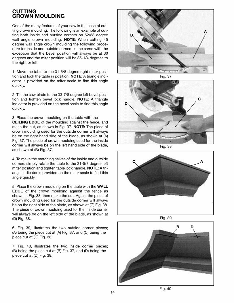
One of the many features of your saw is the ease of cut-ting crown moulding. The following is an example of cut-ting both inside and outside corners on 52/38 degreewall angle crown moulding. NOTE: When cutting 45degree wall angle crown moulding the following proce-dure for inside and outside corners is the same with theexception that the bevel position will always be at 30degrees and the miter position will be 35-1/4 degrees tothe right or left.
1. Move the table to the 31-5/8 degree right miter posi-tion and lock the table in position. NOTE: A triangle indi-cator is provided on the miter scale to find this anglequickly.
2. Tilt the saw blade to the 33-7/8 degree left bevel posi-tion and tighten bevel lock handle. NOTE: A triangleindicator is provided on the bevel scale to find this anglequickly.
3. Place the crown moulding on the table with theCEILING EDGE of the moulding against the fence, andmake the cut, as shown in Fig. 37. NOTE: The piece ofcrown moulding used for the outside corner will alwaysbe on the right hand side of the blade, as shown at (A)Fig. 37. The piece of crown moulding used for the insidecorner will always be on the left hand side of the blade,as shown at (B) Fig. 37.
4. To make the matching halves of the inside and outsidecorners simply rotate the table to the 31-5/8 degree leftmiter position and tighten table lock handle. NOTE: A tri-angle indicator is provided on the miter scale to find thisangle quickly.
5. Place the crown moulding on the table with the WALLEDGE of the crown moulding against the fence asshown in Fig. 38, then make the cut. Again, the piece ofcrown moulding used for the outside corner will alwaysbe on the right side of the blade, as shown at (C) Fig. 38.The piece of crown moulding used for the inside cornerwill always be on the left side of the blade, as shown at(D) Fig. 38.
6. Fig. 39, illustrates the two outside corner pieces; (A) being the piece cut at (A) Fig. 37, and (C) being thepiece cut at (C) Fig. 38.
7. Fig. 40, illustrates the two inside corner pieces; (B) being the piece cut at (B) Fig. 37, and (D) being thepiece cut at (D) Fig. 38.
BA

15
BRUSH INSPECTION AND REPLACEMENTCAUTION: BEFORE INSPECTING THE BRUSHES,DISCONNECT THE MACHINE FROM THE POWERSOURCE.
Brush life varies. It depends on the load on the motor.Check the brushes after the first 50 hours of use for anew machine or after a new set of brushes has beeninstalled.
After the first check, examine them after about 10 hoursof use until such time that replacement is necessary.
The brush holders (A) Fig. 41, are located on the motorhousing opposite each other. Fig. 42, illustrates one ofthe brushes removed for inspection. When the carbon oneither brush is worn to 3/16" in length or if either springor shunt wire is burned or damaged in any way, replaceboth brushes. If the brushes are found serviceable afterremoving, reinstall them in the same position asremoved.
Fig. 41
Fig. 42
TABLE HAZARD AREAWARNING: THE AREA INSIDE THE TWO RED LINES (A) FIG. 43, ON THE TABLE IS DESIGNATED AS A HAZARD ZONE. NEVER PLACE YOUR HANDS INSIDE THIS AREA WHILE THE TOOL IS BEING OPERATED.
Fig. 43
A
A

161616
PARTS, SERVICE OR WARRANTY ASSISTANCEAll Delta Machines and accessories are manufactured to high quality standards and are serviced bya network of Porter-Cable Delta Factory Service Centers and Delta Authorized Service Stations. Toobtain additional information regarding your Delta quality product or to obtain parts, service, warrantyassistance, or the location of the nearest service outlet, please call 1-800-223-7278 ( in Canada call 1-800-463-3582).
Delta Building Trades and Home Shop MachineryTwo Year Limited Warranty
Delta will repair or replace, at its expense and at its option, any Delta machine, machine part, or machine accessory whichin normal use has proven to be defective in workmanship or material, provided that the customer returns the product pre-paid to a Delta factory service center or authorized service station with proof of purchase of the product within two yearsand provides Delta with reasonable opportunity to verify the alleged defect by inspection. Delta may require that electricmotors be returned prepaid to a motor manufacturer’s authorized station for inspection and repair or replacement. Deltawill not be responsible for any asserted defect which has resulted from normal wear, misuse, abuse or repair or alterationmade or specifically authorized by anyone other than an authorized Delta Service facility or representative. Under no cir-cumstances will Delta be liable for incidental or consequential damages resulting from defective products. This warranty isDelta’s sole warranty and sets forth the customer’s exclusive remedy, with respect to defective products; all other war-ranties, express or implied, whether of merchantability, fitness for purpose, or otherwise, are expressly disclaimed by Delta.
ACCESSORIESA complete line of accessories is available from your Delta Supplier, Porter-Cable Delta Factory Service Centers,and Delta Authorized Service Stations. Please visit our Web Site www.deltamachinery.com for a catalog orfor the name of your nearest supplier.
WARNING: Since accessories, other than those offered by Delta, have not been tested with this product, use of such accessories could be hazardous. For safest operation, only Delta recommended accessories should be used with this product.
36-221 WORK CLAMP36-224 EXTENSION BAR AND STOP
The following are trademarks of PORTER-CABLE DELTA Corporation (Las siguientes son marcas registradas de PORTER-CABLE S.A.): BAMMER®, INNOVATION THAT WORKS®, JETSTREAM®, LASERLOC®, OMNIJIG®, POCKET CUTTER®, PORTA-BAND®, PORTA-PLANE®,PORTER-CABLE®, QUICKSAND®, SANDTRAP®, SAW BOSS®, SPEED-BLOC®, SPEEDMATIC®, SPEEDTRONIC®, STAIR-EASE®, THE PRO-FESSIONAL EDGE®, THE PROFESSIONAL SELECT®, TIGER CUB®, TIGER SAW®, TORQBUSTER®, WHISPER SERIES®, DURATRONIC™,FLEX™, FRAME SAW™, MICRO-SET™, MORTEN™, NETWORK™, RIPTIDE™, TRU-MATCH™, WOODWORKER’S CHOICE™.Trademarks noted with ® are registered in the United States Patent and Trademark Office and may also be registered in other countries.Las Marcas Registradas con el signo de ® son registradas por la Oficina de Registros y Patentes de los Estados Unidos y también puedenestar registradas en otros países.
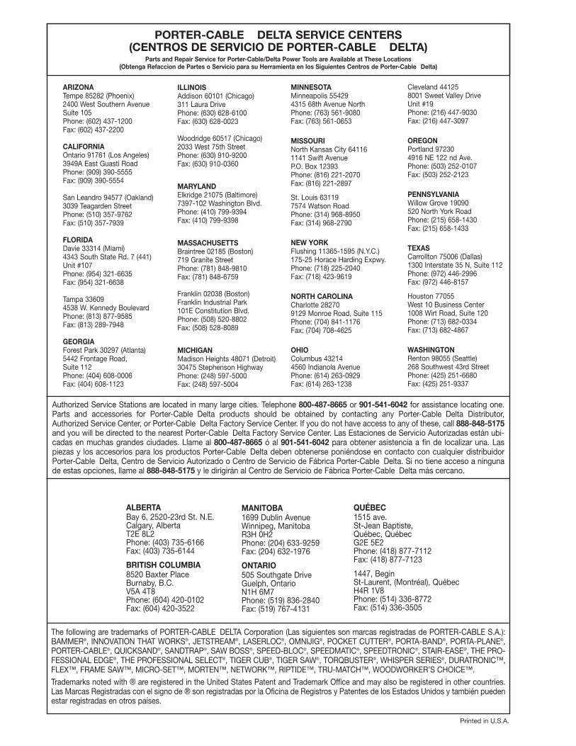
PORTER-CABLE DELTA SERVICE CENTERS(CENTROS DE SERVICIO DE PORTER-CABLE DELTA)
Parts and Repair Service for Porter-Cable/Delta Power Tools are Available at These Locations(Obtenga Refaccion de Partes o Servicio para su Herramienta en los Siguientes Centros de Porter-Cable Delta)
Authorized Service Stations are located in many large cities. Telephone 800-487-8665 or 901-541-6042 for assistance locating one.Parts and accessories for Porter-Cable Delta products should be obtained by contacting any Porter-Cable Delta Distributor,Authorized Service Center, or Porter-Cable Delta Factory Service Center. If you do not have access to any of these, call 888-848-5175and you will be directed to the nearest Porter-Cable Delta Factory Service Center. Las Estaciones de Servicio Autorizadas están ubi-cadas en muchas grandes ciudades. Llame al 800-487-8665 ó al 901-541-6042 para obtener asistencia a fin de localizar una. Laspiezas y los accesorios para los productos Porter-Cable Delta deben obtenerse poniéndose en contacto con cualquier distribuidorPorter-Cable Delta, Centro de Servicio Autorizado o Centro de Servicio de Fábrica Porter-Cable Delta. Si no tiene acceso a ningunade estas opciones, llame al 888-848-5175 y le dirigirán al Centro de Servicio de Fábrica Porter-Cable Delta más cercano.
ARIZONATempe 85282 (Phoenix)2400 West Southern AvenueSuite 105Phone: (602) 437-1200Fax: (602) 437-2200
CALIFORNIAOntario 91761 (Los Angeles)3949A East Guasti RoadPhone: (909) 390-5555Fax: (909) 390-5554
San Leandro 94577 (Oakland)3039 Teagarden StreetPhone: (510) 357-9762Fax: (510) 357-7939
FLORIDADavie 33314 (Miami)4343 South State Rd. 7 (441)Unit #107Phone: (954) 321-6635Fax: (954) 321-6638
Tampa 33609 4538 W. Kennedy BoulevardPhone: (813) 877-9585Fax: (813) 289-7948
GEORGIAForest Park 30297 (Atlanta)5442 Frontage Road,Suite 112Phone: (404) 608-0006Fax: (404) 608-1123
ILLINOISAddison 60101 (Chicago)311 Laura DrivePhone: (630) 628-6100Fax: (630) 628-0023
Woodridge 60517 (Chicago)2033 West 75th StreetPhone: (630) 910-9200Fax: (630) 910-0360
MARYLANDElkridge 21075 (Baltimore)7397-102 Washington Blvd.Phone: (410) 799-9394Fax: (410) 799-9398
MASSACHUSETTSBraintree 02185 (Boston)719 Granite StreetPhone: (781) 848-9810Fax: (781) 848-6759
Franklin 02038 (Boston)Franklin Industrial Park101E Constitution Blvd.Phone: (508) 520-8802Fax: (508) 528-8089
MICHIGANMadison Heights 48071 (Detroit)30475 Stephenson HighwayPhone: (248) 597-5000Fax: (248) 597-5004
MINNESOTAMinneapolis 554294315 68th Avenue NorthPhone: (763) 561-9080Fax: (763) 561-0653
MISSOURINorth Kansas City 641161141 Swift AvenueP.O. Box 12393Phone: (816) 221-2070Fax: (816) 221-2897
St. Louis 631197574 Watson RoadPhone: (314) 968-8950Fax: (314) 968-2790
NEW YORKFlushing 11365-1595 (N.Y.C.)175-25 Horace Harding Expwy.Phone: (718) 225-2040Fax: (718) 423-9619
NORTH CAROLINACharlotte 282709129 Monroe Road, Suite 115Phone: (704) 841-1176Fax: (704) 708-4625
OHIOColumbus 432144560 Indianola AvenuePhone: (614) 263-0929Fax: (614) 263-1238
Cleveland 441258001 Sweet Valley DriveUnit #19Phone: (216) 447-9030Fax: (216) 447-3097
OREGONPortland 972304916 NE 122 nd Ave.Phone: (503) 252-0107Fax: (503) 252-2123
PENNSYLVANIAWillow Grove 19090520 North York RoadPhone: (215) 658-1430Fax: (215) 658-1433
TEXASCarrollton 75006 (Dallas)1300 Interstate 35 N, Suite 112Phone: (972) 446-2996Fax: (972) 446-8157
Houston 77055West 10 Business Center1008 Wirt Road, Suite 120Phone: (713) 682-0334Fax: (713) 682-4867
WASHINGTONRenton 98055 (Seattle)268 Southwest 43rd StreetPhone: (425) 251-6680Fax: (425) 251-9337
Printed in U.S.A.
ALBERTABay 6, 2520-23rd St. N.E.Calgary, AlbertaT2E 8L2Phone: (403) 735-6166Fax: (403) 735-6144
BRITISH COLUMBIA8520 Baxter PlaceBurnaby, B.C.V5A 4T8Phone: (604) 420-0102Fax: (604) 420-3522
MANITOBA1699 Dublin AvenueWinnipeg, ManitobaR3H 0H2Phone: (204) 633-9259Fax: (204) 632-1976
ONTARIO505 Southgate DriveGuelph, OntarioN1H 6M7Phone: (519) 836-2840Fax: (519) 767-4131
QUÉBEC1515 ave.St-Jean Baptiste,Québec, QuébecG2E 5E2Phone: (418) 877-7112Fax: (418) 877-7123
1447, BeginSt-Laurent, (Montréal), QuébecH4R 1V8Phone: (514) 336-8772Fax: (514) 336-3505