Embed Size (px)
Citation preview

12” COMPOUND SLIDEMITER SAW
91852ASSEMBLY And OpErAting inStructiOnS
distributed exclusively by Harbor Freight tools®.3491 Mission Oaks Blvd., Camarillo, CA 93011
Visit our website at: http://www.harborfreight.com
read this material before using this product. Failure to do so can result in serious injury. SAVE tHiS MAnuAL.
Copyright© 2008 by Harbor Freight Tools®. All rights reserved. No portion of this manual or any artwork contained herein may be reproduced in any shape or form without the express written consent of Harbor Freight Tools. Diagrams within this manual may not be drawn proportionally. Due to continuing improvements, actual product may differ slightly from the product described herein. Tools required for assembly and service may not be included.
For technical questions or replacement parts, please call 1-800-444-3353.

SKU 91852 For technical questions, please call 1-800-444-3353. PAGE 2
PRODUCT SPECIFICATIONS
SAVE THIS MANUAL
You will need this manual for the safety warnings and precautions, assembly, operat-ing, inspection, maintenance and cleaning procedures, parts list and assembly diagram. Keep your invoice with this manual. Write the invoice number on the inside of the front cover. Keep this manual and invoice in a safe and dry place for future reference.
GENERAL SAFETY RULES
WARNING!READ AND UNDERSTAND ALL INSTRUCTIONS
Failure to follow all instructions listed in the followingpages may result in electric shock, fire, and/or serious injury.
SAVE THESE INSTRUCTIONS
WORK AREA
1. Keep your work area clean and well lit. Cluttered benches and dark areas invite accidents.
2. Do not operate power tools in explosive atmospheres, such as in the pres-ence of flammable liquids, gases, or dust. Power tools create sparks which may ignite flammables.
E105017
66AJ
REV 06/05; REV 02/06
Electrical Requirements 120 V / 60 Hz / 1800 Input Watts15 Amp / 4100 RPM Motor
Power Cord Plug Two Prong, Polarized
Power Switch Single Pull Trigger Type
Laser Input Power Two “AAA” Batteries
Laser Switch Push Button
Saw Blade (Included) Diameter/Type 12” Diameter100-Tooth Carbide Tipped5000 RPM Rated
Arbor Size 1” Diameter
Crosscut Capacity 12-3/4” x 4” Vertical @ 90°12-3/4” x 1-15/16” Vertical @ 45°
Blade Tilt Capacity 0° - 45° R & L Miter / 0° - 45° L-Compound
Positive Stops 0°, 15°, 22.5°, 30°, 45° L – R Miter0°, 45° L Bevel
Turntable Diameter 13-7/8”
Overall Table Size 22-3/4” L x 6-1/2” W
Overall Dimensions 34-1/2” L x 22-7/8” W x 26-1/4” H
Weight 44 Pounds

SKU 91852 For technical questions, please call 1-800-444-3353. PAGE 3
3. Keep bystanders, children, and visitors away while operating a power tool. Distractions can cause you to lose control. Protect others in the work area from debris such as chips and sparks. Provide barriers or shields as needed.
4. Grounded tools must be plugged into an outlet properly installed and grounded in accordance with all codes and ordinances. Never remove the grounding prong or modify the plug in any way. Do not use any adapter plugs. Check with a qualified electrician if you are in doubt as to whether the outlet is properly grounded. If the tools should electrically malfunction or break down, grounding provides a low resistance path to carry electricity away from the user.
5. Double insulated tools are equipped with a polarized plug (one blade is wider than the other). This plug will fit in a polarized outlet only one way. If the plug does not fit fully in the outlet, reverse the plug. If it still does not fit, contact a qualified electrician to install a polarized outlet. Do not change the plug in any way. Double insulation eliminates the need for the three wire grounded power cord and grounded power supply system.
6. Avoid body contact with grounded surfaces such as pipes, radiators, rang-es, and refrigerators. There is an increased risk of electric shock if your body is grounded.
7. Do not expose power tools to rain or wet conditions. Water entering a power tool will increase the risk of electric shock.
8. Do not abuse the Power Cord. Never use the Power Cord to carry the tools or pull the Plug from an outlet. Keep the Power Cord away from heat, oil, sharp edges, or moving parts. Replace damaged Power Cords immediately. Damaged Power Cords increase the risk of electric shock.
9. When operating a power tool outside, use an outdoor extension cord marked “W-A” or “W”. These extension cords are rated for outdoor use, and reduce the risk of electric shock.
ELECTRICAL SAFETY
PERSONAL SAFETY
10. Stay alert. Watch what you are doing, and use common sense when operat-ing a power tool. Do not use a power tool while tired or under the influence of drugs, alcohol, or medication. A moment of inattention while operating power tools may result in serious personal injury.
11. Dress properly. Do not wear loose clothing or jewelry. Contain long hair. Keep your hair, clothing, and gloves away from moving parts. Loose clothes, jewelry, or long hair can be caught in moving parts.

SKU 91852 For technical questions, please call 1-800-444-3353. PAGE 4
12. Avoid accidental starting. Be sure the Power Switch is off before plugging in. Carrying power tools with your finger on the Power Switch, or plugging in power tools with the Power Switch on, invites accidents.
13. Remove adjusting keys or wrenches before turning the power tool on. A wrench or a key that is left attached to a rotating part of the power tool may result in personal injury.
14. Do not overreach. Keep proper footing and balance at all times. Proper footing and balance enables better control of the power tool in unexpected situa-tions.
15. Use safety equipment. Always wear eye protection. Dust mask, non-skid safety shoes, hard hat or hearing protection must be used for appropriate condi-tions
TOOL USE AND CARE
16. Use clamps or other practical ways to secure and support the workpiece to a stable platform. Holding the work by hand is unstable and may lead to loss of control. Only work on a workpiece that is properly secured.
17. Do not force the tool. Use the correct tool for your application. The correct tool will do the job better and safer at the rate for which it is designed.
18. Do not use the power tool if the Power Switch does not turn it on or off. Any tool that cannot be controlled with the Power Switch is dangerous and must be replaced.
19. Disconnect the Power Cord Plug from the power source before making any adjustments, changing accessories, or storing the tool. Such preventive safety measures reduce the risk of starting the tool accidentally.
20. Store idle tools out of reach of children and other untrained persons. Tools are dangerous in the hands of untrained users.
21. Maintain tools with care. Keep cutting tools sharp and clean. Properly maintained tools with a sharp cutting edge are less likely to bind and are easier to control. Do not use a damaged tool. Tag damaged tools “Do not use” until repaired.
22. Check for misalignment or binding of guards and other moving parts, breakage of parts, cracking or breakage of the Saw Blade, and any other condition that may affect the tool’s operation. If damaged, have the tool serviced before using. Many accidents are caused by poorly maintained tools.
23. Use only accessories that are recommended by the manufacturer for your model. Accessories that may be suitable for one tool may become hazardous when used on another tool.
SERVICE
24. Tool service must be performed only by qualified repair personnel. Service or maintenance performed by unqualified personnel could result in a risk of injury.

SKU 91852 For technical questions, please call 1-800-444-3353. PAGE 5
SPECIFIC SAFETY RULES1. Maintain a safe working environment. Keep the work area well lit. Make sure
there is adequate surrounding workspace. Always keep the work area free of obstructions, grease, oil, trash, and other debris. Do not use the Miter Saw in areas near flammable chemicals, dusts, and vapors. Do not use this product in a damp or wet location.
2. Maintain labels and nameplates on the Miter Saw. These carry important information. If unreadable or missing, contact Harbor Freight Tools for a replace-ment.
3. Do not force the equipment. This Miter Saw will do the work better and safer at the speed and capacity for which it was designed.
4. Keep all guards in place and in working order.
5. Remove all adjusting wrenches from the Miter Saw before turning it on.
6. Do not abuse the Power Cord. Do not use the Power Cord to pull its Plug from an electrical outlet. Keep the Power Cord away from heat, oil, sharp edges, and moving parts. Route the Power Cord safely. Protect the Power Cord from being damaged by other equipment in the work area. Do not route the Power Cord where it can be walked on or tripped over. Replace a damaged Power Cord immediately.
7. Do not use this Miter Saw for cutting metals or brittle materials. Do not cut dangerous materials, such as asbestos which can cause harmful dust or vapors.
8. To avoid accidental injury, always wear heavy duty work gloves when changing a Saw Blade.
9. Before using the Miter Saw, make sure the Saw Blade is properly mounted on the Saw Spindle. Make sure the Saw Blade is balanced, and is not cracked or bent.
10. The Saw Blade will become hot while cutting. Allow the Saw Blade to com-pletely cool before touching.
11. Make sure the workpiece is free from nails and any other foreign objects which can damage the Saw Blade.
12. Keep your body positioned to either side of the Saw Blade, but not in line with the Saw Blade. “Kickback” can cause the Saw to jump backwards.
25. When servicing a tool, use only identical replacement parts. Follow in-structions in the “Inspection, Maintenance, And Cleaning” section of this manual. Use of unauthorized parts or failure to follow maintenance instructions may create a risk of electric shock or injury.

SKU 91852 For technical questions, please call 1-800-444-3353. PAGE 6
13. Causes and operator prevention of “kickback”: Kickback is a sudden reaction to a pinched, bound, or misaligned Saw Blade, causing an uncontrolled Saw to lift up and out of the workpiece toward the operator. When the Saw Blade is pinched or bound tightly by the kerf closing down, the Saw Blade stalls and the Motor reaction drives the tool rapidly toward the operator. If the Saw Blade becomes twisted or misaligned in the cut, the teeth at the back edge of the Saw Blade can dig into the top surface of the workpiece, causing the Saw Blade to climb out of the kerf and jump toward the operator. Kickback is a result of tool misuse and/or incorrect operating procedures or conditions and can be minimized by taking proper precautions as given below:
A. Maintain a firm grip with both hands on the Saw, and position your body and arm to allow you to resist kickback forces.
B. When the Saw Blade is binding, or when interrupting a cut for any rea-son, release the Power Switch and hold the Saw motionless in the work-piece until the Saw Blade comes to a complete stop. Never attempt to remove the Saw from the workpiece or pull the Saw backward while the Saw Blade is in motion or kickback can occur.
C. When restarting the Saw in the workpiece, center the Saw Blade in the kerf and check that the saw teeth are not engaged into the workpiece. If the Saw Blade is binding, it may walk up or kickback from the workpiece as the Saw is restarted.
D. Support large panels to minimize the risk of Saw Blade pinching and kickback. Large panels tend to sag under their own weight. Supports must be placed under the panel on both sides, near the line of cut and near the edge of the panel.
E. Do not use a dull or damaged Saw Blade. Unsharpened or improperly set Saw Blades produce a narrow kerf causing excessive friction, Saw Blade binding and kickback.
F. Make sure all Saw adjustments are tight and secure before making a cut. If Saw adjustments shift while cutting, it may cause binding and kickback.
14. WARNING! The Lock Pin (128) should always be activated in the “locked down” position when the Saw is not being used and when the Saw is being transported. The Lock Pin should be activated in the “locked up” position when changing Saw Blades. NEVER use the Lock Pin in any cut-ting operation. The Lock Pin allows the operator to lock the Saw Blade in position, preventing the Saw Blade from being raised or lowered.
15. Allow the Saw Blade to spin up to full speed before feeding it into the work-piece. Do not force the Saw Blade into the workpiece when cutting. Apply moderate pressure, allowing the Saw Blade to cut without being forced. When turning off the Saw, allow the Saw Blade to spin down and stop on its own. Do not press against the Saw Blade to stop it.
SKU 91852 For technical questions, please call 1-800-444-3353. PAGE 7
16. Turn off the Saw and allow the Saw Blade to stop on its own if the Saw Blade is to be backed out of an uncompleted cut.
17. Industrial applications must follow OSHA requirements.
18. The Laser on the Miter Saw is rated as a Class 2. Do not stare directly at the Laser beam. A hazard may exist if you deliberately stare into the beam. Never aim the Laser beam at any person, animal, or an object other than the work-piece.
19. Make sure the Laser beam is aimed at a sturdy workpiece without reflective surfaces. Reflective surfaces are not suitable for Laser applications, as the re-flective surface may direct the Laser beam back at the operator, causing potential eye damage.
20. Do not attempt to alter the Laser or replace it with a different type. Doing so may result in hazardous radiation exposure.
21. Never attempt to remove material stuck in the moving parts of the Miter Saw while the machine is plugged in and running.
22. Whenever possible, use clamps or other safe, practical ways to hold and support the workpiece. Do not attempt to cut material that does not have a flat surface, unless a suitable support is used.
23. Always keep hands and fingers away from the spinning Saw Blade.
24. Use eye, hearing, and breathing protection. Always wear ANSI-approved safety impact eye goggles, hearing protectors, and dust masks or respirator when working with the Miter Saw.
25. Do not use this product if under the influence of alcohol or drugs. Read warning labels on prescriptions to determine if your judgement or reflexes are im-paired while taking drugs. If there is any doubt, do not attempt to use this prod-uct.
26. Maintain this product with care. Keep the Miter Saw clean and dry for better and safer performance. For your safety, service and maintenance should be per-formed regularly by a qualified technician.
27. Use the right tool or attachment for the right job. Do not attempt to force a small tool or attachment to do the work of a larger industrial tool or attachment. There are certain applications for which this product was designed. It will do the job better and more safely at the rate for which it was intended. Do not modify this product, and do not use this product for a purpose for which it was not in-tended.
28. Always turn off the Miter Saw and unplug the Power Cord (27) from its electrical outlet before changing accessories or performing inspection, maintenance, or cleaning procedures.
SKU 91852 For technical questions, please call 1-800-444-3353. PAGE 8
29. WARNING! People with pacemakers should consult their physician(s) before using this product. Operation of electrical equipment in close proximity to a heart pacemaker could cause interference to or failure of the pacemaker.
30. WARNING! Some dust created by power sanding, sawing, grinding, drilling, and other construction activities, contain chemicals known (to the State of Califor-nia) to cause cancer, birth defects or other reproductive harm. Some examples of these chemicals are: lead from lead-based paints, crystalline silica from bricks and cement or other masonry products, arsenic and chromium from chemically treated lumber. Your risk from these exposures varies, depending on how often you do this type of work. To reduce your exposure to these chemicals: work in a well ventilated area, and work with approved safety equipment, such as those dust masks that are specially designed to filter out microscopic particles. (California Health & Safety Code 25249.5, et seq.)
31. WARNING! The warnings, precautions, and instructions discussed in this manual cannot cover all possible conditions and situations that may occur. The operator must understand that common sense and caution are factors which can-not be built into this product, but must be supplied by the operator.
GROUNDING
WARNING!Improperly connecting the grounding wire can result in the risk of electric
shock. Check with a qualified electrician if you are in doubt as to whether the out-let is properly grounded. Do not modify the power cord plug provided withthe tool. Never remove the grounding prong from the plug. Do not use thetool if the power cord or plug is damaged. If damaged, have it repaired bya service facility before use. If the plug will not fit the outlet, have a proper
outlet installed by a qualified electrician.
GROUNDED TOOLS: TOOLS WITH THREE PRONG PLUGS
1. Tools marked with “Grounding Required” have a three wire cord and three prong grounding plug. The plug must be connected to a properly grounded outlet. If the tool should electrically malfunction or break down, grounding provides a low resistance path to carry electricity away from the user, reducing the risk of elec- tric shock. (See Figure A.)
2. The grounding prong in the plug is connected through the green wire inside the cord to the grounding system in the tool. The green wire in the cord must be the only wire connected to the tool’s grounding system and must never be attached to an electrically “live” terminal. (See Figure A.)
SKU 91852 For technical questions, please call 1-800-444-3353. PAGE 9
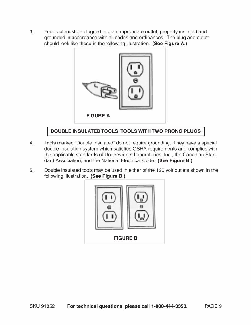
3. Your tool must be plugged into an appropriate outlet, properly installed and grounded in accordance with all codes and ordinances. The plug and outlet should look like those in the following illustration. (See Figure A.)
DOUBLE INSULATED TOOLS: TOOLS WITH TWO PRONG PLUGS
4. Tools marked “Double Insulated” do not require grounding. They have a special double insulation system which satisfies OSHA requirements and complies with the applicable standards of Underwriters Laboratories, Inc., the Canadian Stan-dard Association, and the National Electrical Code. (See Figure B.)
5. Double insulated tools may be used in either of the 120 volt outlets shown in the following illustration. (See Figure B.)
FIGURE A
FIGURE B

SKU 91852 For technical questions, please call 1-800-444-3353. PAGE 10
EXTENSION CORDS
1. Double Insulated tools can use either a two or three wire extension cord.
2. As the distance from the supply outlet increases, you must use a heavier gauge extension cord. Using extension cords with inadequately sized wire causes a serious drop in voltage, resulting in loss of power and possible tool damage. (See Figure C)
3. The smaller the gauge number of the wire, the greater the capacity of the cord. For example, a 14 gauge cord can carry a higher current than a 16 gauge cord. (See Figure C)
4. When using more than one extension cord to make up the total length, make sure each cord contains at least the minimum wire size required. (See Figure C)
5. If you are using one extension cord for more than one tool, add the nameplate amperes and use the sum to determine the required minimum cord size. (See Figure C)
6. If you are using an extension cord outdoors, make sure it is marked with the suf-fix “W-A” (“W” in Canada) to indicate it is acceptable for outdoor use.
7. Make sure your extension cord is properly wired and in good electrical condition. Always replace a damaged extension cord or have it repaired by a qualified elec-trician before using it.
8. Protect your extension cords from sharp objects, excessive heat, and damp or wet areas.
RECOMMENDED MINIMUM WIRE GAUGE FOR EXTENSION CORDS*(120 OR 240 VOLT)
NAMEPLATEAMPERES
(At Full Load)
EXTENSION CORD LENGTH
25 Feet 50 Feet 75 Feet 100 Feet 150 Feet0 – 2.0 18 18 18 18 16
2.1 – 3.4 18 18 18 16 14
3.5 – 5.0 18 18 16 14 12
5.1 – 7.0 18 16 14 12 12
7.1 – 12.0 18 14 12 10 -
12.1 – 16.0 14 12 10 - -
16.1 – 20.0 12 10 - - -
FIGURE C * Based on limiting the line voltage drop to five volts at 150% of the rated amperes.

SKU 91852 For technical questions, please call 1-800-444-3353. PAGE 11
SYMBOLOGY
V ~A
xxxx/min.no
Double Insulated
Canadian StandardsAssociation
UnderwritersLaboratories, Inc.Volts Alternating
Current
Amperes
No Load RevolutionsPer Minute (RPM)
UNPACKING
When unpacking, check to make sure all the parts shown on the Parts Lists on pages 23 and 26 are included. If any parts are missing or broken, please call Harbor Freight Tools at the number shown on the cover of this manual as soon as possible.
ASSEMBLY AND OPERATING INSTRUCTIONS
NOTE: For additional references to the parts listed in the following pages, refer to the Assembly Diagrams on pages 25 and 26.
To Replace And Install A Saw Blade:
1. WARNING! Prior to performing any assembly and/or adjustment procedures, make sure the Power Cord (27) of the Miter Saw is unplugged from its electrical outlet. Make sure the unit has completely cooled, and wear heavy duty work gloves.
2. When replacing the Saw Blade (4), make sure the new Saw Blade has a diam-eter of 12”, an RPM rating of at least 5000, and an arbor hole of 1” diameter.
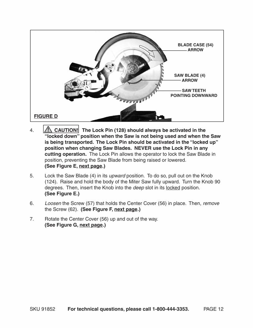
3. When installing a Saw Blade (4), make sure the teeth of the Saw Blade point downward, and that the direction of the arrow shown on the Saw Blade matches the direction of the arrow shown on the Blade Case (54). (See Figure D.)
SKU 91852 For technical questions, please call 1-800-444-3353. PAGE 12
FIGURE D
SAW BLADE (4)ARROW
BLADE CASE (54)ARROW
SAW TEETHPOINTING DOWNWARD
4. CAUTION! The Lock Pin (128) should always be activated in the “locked down” position when the Saw is not being used and when the Saw is being transported. The Lock Pin should be activated in the “locked up” position when changing Saw Blades. NEVER use the Lock Pin in any cutting operation. The Lock Pin allows the operator to lock the Saw Blade in position, preventing the Saw Blade from being raised or lowered. (See Figure E, next page.)
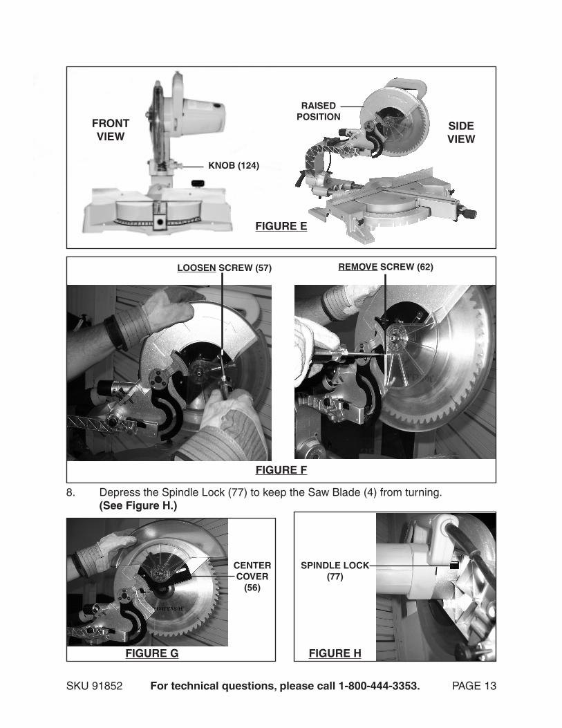
5. Lock the Saw Blade (4) in its upward position. To do so, pull out on the Knob (124). Raise and hold the body of the Miter Saw fully upward. Turn the Knob 90 degrees. Then, insert the Knob into the deep slot in its locked position. (See Figure E.)
6. Loosen the Screw (57) that holds the Center Cover (56) in place. Then, remove the Screw (62). (See Figure F, next page.)
7. Rotate the Center Cover (56) up and out of the way. (See Figure G, next page.)
SKU 91852 For technical questions, please call 1-800-444-3353. PAGE 13
FIGURE E
KNOB (124)
FRONTVIEW
SIDEVIEW
RAISEDPOSITION
8. Depress the Spindle Lock (77) to keep the Saw Blade (4) from turning. (See Figure H.)
LOOSEN SCREW (57) REMOVE SCREW (62)
CENTERCOVER
(56)
FIGURE F
FIGURE G FIGURE H
SPINDLE LOCK(77)
SKU 91852 For technical questions, please call 1-800-444-3353. PAGE 14
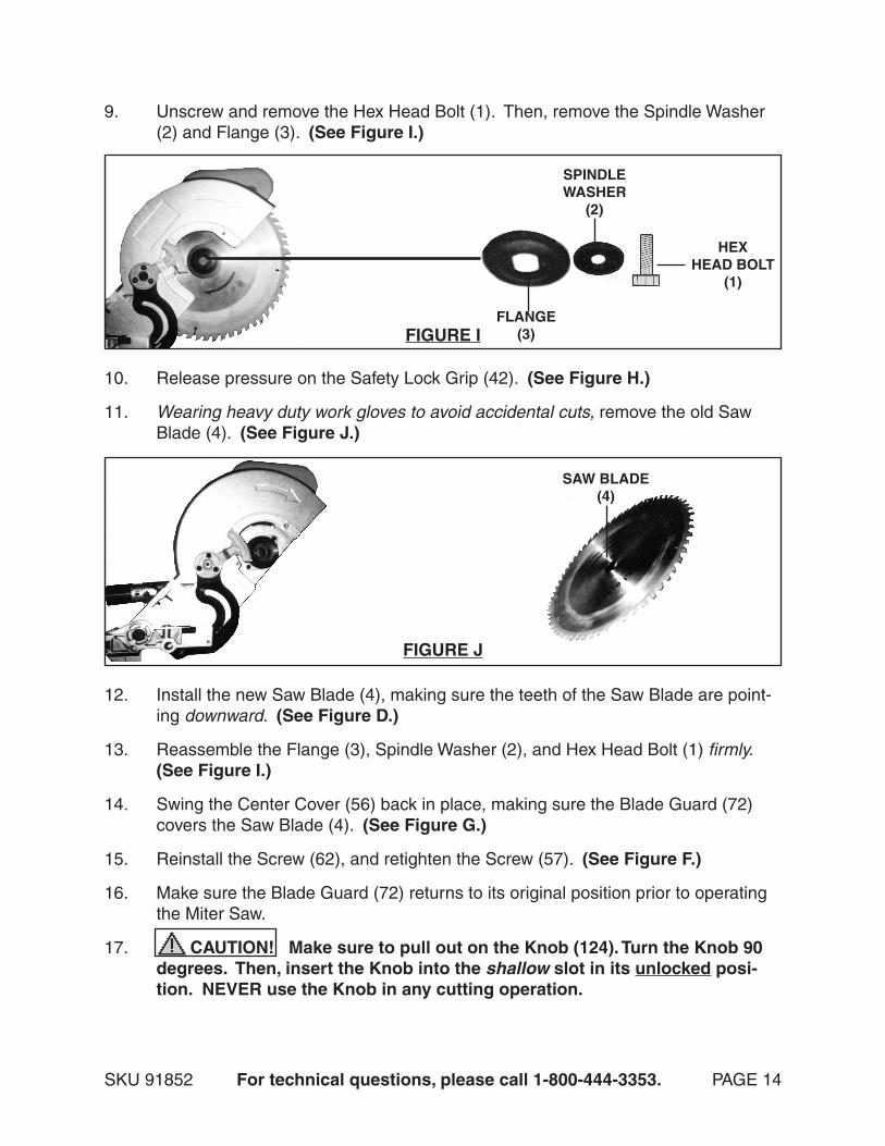
9. Unscrew and remove the Hex Head Bolt (1). Then, remove the Spindle Washer (2) and Flange (3). (See Figure I.)
HEXHEAD BOLT
(1)
SPINDLEWASHER
(2)
FLANGE(3)FIGURE I
10. Release pressure on the Safety Lock Grip (42). (See Figure H.)
11. Wearing heavy duty work gloves to avoid accidental cuts, remove the old Saw Blade (4). (See Figure J.)
SAW BLADE(4)
FIGURE J
12. Install the new Saw Blade (4), making sure the teeth of the Saw Blade are point- ing downward. (See Figure D.)
13. Reassemble the Flange (3), Spindle Washer (2), and Hex Head Bolt (1) firmly. (See Figure I.)
14. Swing the Center Cover (56) back in place, making sure the Blade Guard (72) covers the Saw Blade (4). (See Figure G.)
15. Reinstall the Screw (62), and retighten the Screw (57). (See Figure F.)
16. Make sure the Blade Guard (72) returns to its original position prior to operating the Miter Saw.
17. CAUTION! Make sure to pull out on the Knob (124). Turn the Knob 90 degrees. Then, insert the Knob into the shallow slot in its unlocked posi-tion. NEVER use the Knob in any cutting operation.
SKU 91852 For technical questions, please call 1-800-444-3353. PAGE 15
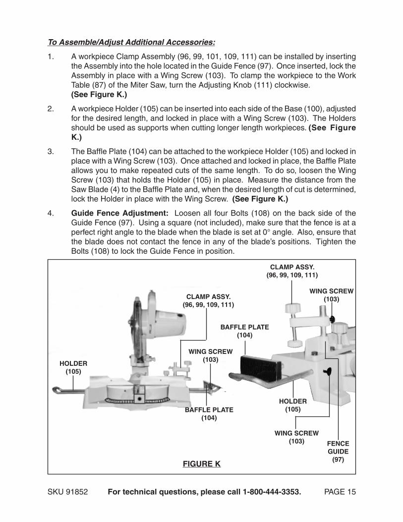
To Assemble/Adjust Additional Accessories:
1. A workpiece Clamp Assembly (96, 99, 101, 109, 111) can be installed by inserting the Assembly into the hole located in the Guide Fence (97). Once inserted, lock the Assembly in place with a Wing Screw (103). To clamp the workpiece to the Work Table (87) of the Miter Saw, turn the Adjusting Knob (111) clockwise. (See Figure K.)
2. A workpiece Holder (105) can be inserted into each side of the Base (100), adjusted for the desired length, and locked in place with a Wing Screw (103). The Holders should be used as supports when cutting longer length workpieces. (See Figure K.)
3. The Baffle Plate (104) can be attached to the workpiece Holder (105) and locked in place with a Wing Screw (103). Once attached and locked in place, the Baffle Plate allows you to make repeated cuts of the same length. To do so, loosen the Wing Screw (103) that holds the Holder (105) in place. Measure the distance from the Saw Blade (4) to the Baffle Plate and, when the desired length of cut is determined, lock the Holder in place with the Wing Screw. (See Figure K.)
4. Guide Fence Adjustment: Loosen all four Bolts (108) on the back side of the Guide Fence (97). Using a square (not included), make sure that the fence is at a perfect right angle to the blade when the blade is set at 0° angle. Also, ensure that the blade does not contact the fence in any of the blade’s positions. Tighten the Bolts (108) to lock the Guide Fence in position.
FIGURE K
BAFFLE PLATE(104)
BAFFLE PLATE(104)
HOLDER(105)
HOLDER(105)
WING SCREW(103)
WING SCREW(103)
WING SCREW(103)
CLAMP ASSY.(96, 99, 109, 111)
CLAMP ASSY.(96, 99, 109, 111)
FENCEGUIDE
(97)
SKU 91852 For technical questions, please call 1-800-444-3353. PAGE 16
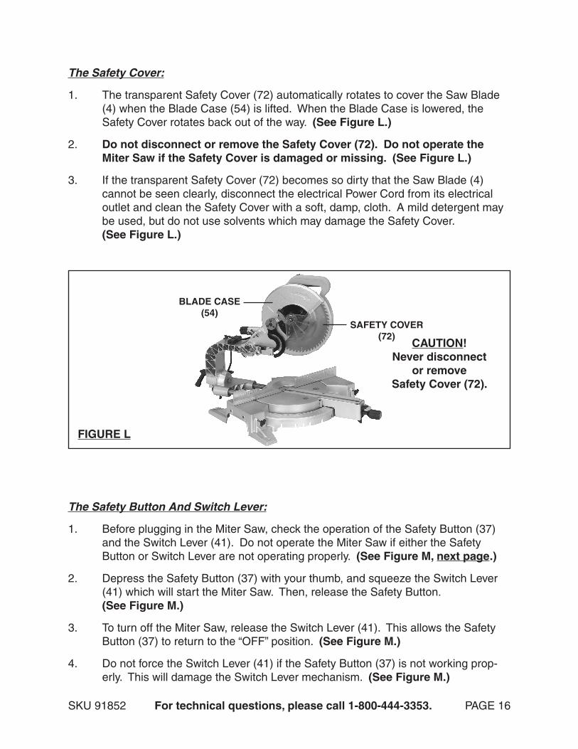
The Safety Cover:
1. The transparent Safety Cover (72) automatically rotates to cover the Saw Blade (4) when the Blade Case (54) is lifted. When the Blade Case is lowered, the Safety Cover rotates back out of the way. (See Figure L.)
2. Do not disconnect or remove the Safety Cover (72). Do not operate the Miter Saw if the Safety Cover is damaged or missing. (See Figure L.)
3. If the transparent Safety Cover (72) becomes so dirty that the Saw Blade (4) cannot be seen clearly, disconnect the electrical Power Cord from its electrical outlet and clean the Safety Cover with a soft, damp, cloth. A mild detergent may be used, but do not use solvents which may damage the Safety Cover. (See Figure L.)
SAFETY COVER(72)
BLADE CASE(54)
FIGURE L
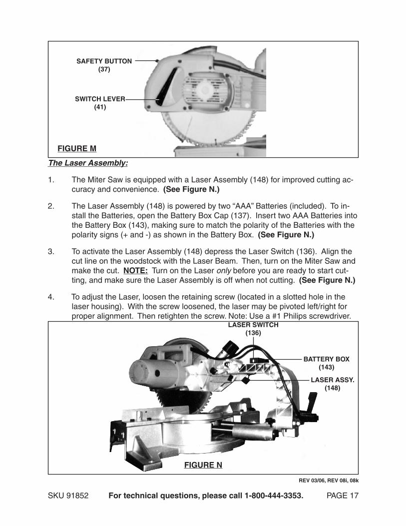
The Safety Button And Switch Lever:
1. Before plugging in the Miter Saw, check the operation of the Safety Button (37) and the Switch Lever (41). Do not operate the Miter Saw if either the Safety Button or Switch Lever are not operating properly. (See Figure M, next page.)
2. Depress the Safety Button (37) with your thumb, and squeeze the Switch Lever (41) which will start the Miter Saw. Then, release the Safety Button. (See Figure M.)
3. To turn off the Miter Saw, release the Switch Lever (41). This allows the Safety Button (37) to return to the “OFF” position. (See Figure M.)
4. Do not force the Switch Lever (41) if the Safety Button (37) is not working prop-erly. This will damage the Switch Lever mechanism. (See Figure M.)
CAUTION!Never disconnect
or removeSafety Cover (72).
SKU 91852 For technical questions, please call 1-800-444-3353. PAGE 17
SWITCH LEVER(41)
SAFETY BUTTON(37)
FIGURE M
The Laser Assembly:
1. The Miter Saw is equipped with a Laser Assembly (148) for improved cutting ac-curacy and convenience. (See Figure N.)
2. The Laser Assembly (148) is powered by two “AAA” Batteries (included). To in-stall the Batteries, open the Battery Box Cap (137). Insert two AAA Batteries into the Battery Box (143), making sure to match the polarity of the Batteries with the polarity signs (+ and -) as shown in the Battery Box. (See Figure N.)
3. To activate the Laser Assembly (148) depress the Laser Switch (136). Align the cut line on the woodstock with the Laser Beam. Then, turn on the Miter Saw and make the cut. NOTE: Turn on the Laser only before you are ready to start cut-ting, and make sure the Laser Assembly is off when not cutting. (See Figure N.)
4. To adjust the Laser, loosen the retaining screw (located in a slotted hole in the laser housing). With the screw loosened, the laser may be pivoted left/right for proper alignment. Then retighten the screw. Note: Use a #1 Philips screwdriver.
LASER ASSY.(148)
LASER SWITCH(136)
BATTERY BOX(143)
FIGURE N
REV 03/06, REV 08i, 08k

SKU 91852 For technical questions, please call 1-800-444-3353. PAGE 18
Adjust The Cutting Depth:
1. WARNING! Prior to performing this procedure, make sure the Power Cord (27) of the Miter Saw is unplugged from its electrical outlet.
The depth of cut may be adjusted to a maximum of 4” at 90°, and 1-15/16” at 45°.2.
Loosen the Wing Screw (103) and pull the Miter Saw’s Motor Housing (31) for-3. ward as far as it will go. Notice whether the edge of the Saw Blade (4) passes completely through the Kerf Board (151). (See Figure P, next page)
If the Saw Blade (4) does not pass completely through the Kerf Board (151), 4. lower the Saw Blade slightly by turning the two Bolts (133A,133B) counterclock-wise. (See Figure P)
The rear Short Bolt (133A) should be adjusted for maximum allowable depth of 5. cut. The forward Long Bolt (133B) is used in conjunction with the Arm Stop Plate (135). The Long Bolt (133B) can be adjusted for a secondary, less deep cut, if desired. Pivot the Arm Stop Plate (135) outward to use the front stop, or push the Arm Stop Plate (135) inward, and the Long Bolt (133B) will bypass it, allowing full depth of cut.
After making the adjustments to the two Bolts (133A, 133B)6. , tighten the two Jam nuts (159) to keep the two Bolts (133A, 133B) from moving. (See Photo Above) After adjusting the two Bolts (133A,133B), press down on the Miter Saw and
ELBOW DUST CHUTE (66)(OUTSIDE DIAMETER = 1-3/8”)
The Elbow Dust Chute:
1. The Elbow Dust Chute (66) exhausts the wood chips and saw dust when the Miter Saw is in operation. (See Figure O.)
2. The outside diameter of the Elbow Dust Chute is 1-3/8”. Attach Dust Collection Bag (158) to the Elbow Dust Chute or attach vacuum hose (not included). It is recommended that only a qualified technician attach a vacuum hose. (See Figure O.)
FIGURE O
REV 07/05;REV 12/05
(ARM STOP PLATE 135)
(133B)(133A)
Depth Adjustment Parts Closeup Photo
(159)
SKU 91852 For technical questions, please call 1-800-444-3353. PAGE 19
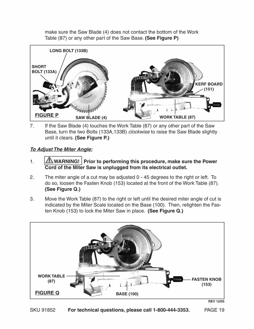
make sure the Saw Blade (4) does not contact the bottom of the Work Table (87) or any other part of the Saw Base. (See Figure P)
WORK TABLE (87)
KERF BOARD(151)
SAW BLADE (4)FIGURE P
LONG BOLT (133B)
SHORT BOLT (133A)
7. If the Saw Blade (4) touches the Work Table (87) or any other part of the Saw Base, turn the two Bolts (133A,133B) clockwise to raise the Saw Blade slightly until it clears. (See Figure P.)
To Adjust The Miter Angle:
1. WARNING! Prior to performing this procedure, make sure the Power Cord of the Miter Saw is unplugged from its electrical outlet.
2. The miter angle of a cut may be adjusted 0 - 45 degrees to the right or left. To do so, loosen the Fasten Knob (153) located at the front of the Work Table (87). (See Figure Q.)
3. Move the Work Table (87) to the right or left until the desired miter angle of cut is indicated by the Miter Scale located on the Base (100). Then, retighten the Fas-ten Knob (153) to lock the Miter Saw in place. (See Figure Q.)
FASTEN KNOB(153)
BASE (100)
WORK TABLE(87)
FIGURE Q
REV 12/05
SKU 91852 For technical questions, please call 1-800-444-3353. PAGE 20
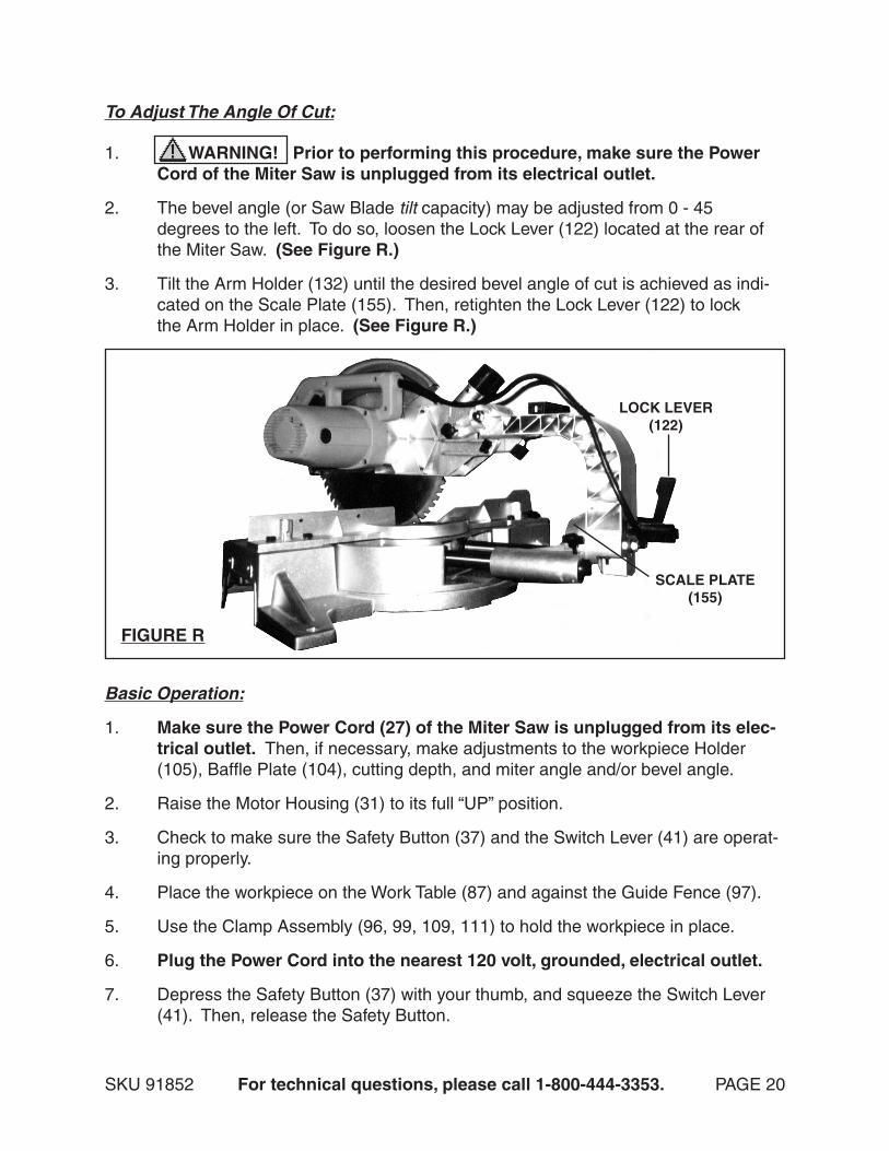
To Adjust The Angle Of Cut:
1. WARNING! Prior to performing this procedure, make sure the Power Cord of the Miter Saw is unplugged from its electrical outlet.
2. The bevel angle (or Saw Blade tilt capacity) may be adjusted from 0 - 45 degrees to the left. To do so, loosen the Lock Lever (122) located at the rear of the Miter Saw. (See Figure R.)
3. Tilt the Arm Holder (132) until the desired bevel angle of cut is achieved as indi- cated on the Scale Plate (155). Then, retighten the Lock Lever (122) to lock the Arm Holder in place. (See Figure R.)
FIGURE R
LOCK LEVER(122)
SCALE PLATE(155)
Basic Operation:
1. Make sure the Power Cord (27) of the Miter Saw is unplugged from its elec-trical outlet. Then, if necessary, make adjustments to the workpiece Holder (105), Baffle Plate (104), cutting depth, and miter angle and/or bevel angle.
2. Raise the Motor Housing (31) to its full “UP” position.
3. Check to make sure the Safety Button (37) and the Switch Lever (41) are operat- ing properly.
4. Place the workpiece on the Work Table (87) and against the Guide Fence (97).
5. Use the Clamp Assembly (96, 99, 109, 111) to hold the workpiece in place.
6. Plug the Power Cord into the nearest 120 volt, grounded, electrical outlet.
7. Depress the Safety Button (37) with your thumb, and squeeze the Switch Lever (41). Then, release the Safety Button.
SKU 91852 For technical questions, please call 1-800-444-3353. PAGE 21
INSPECTION, MAINTENANCE, AND CLEANING
1. WARNING! Always make sure the Switch Lever (41) is in its “OFF” position, and unplug the Power Cord (27) from its 120 volt electrical outlet before performing any inspection, adjustments, maintenance, or cleaning.
2. Before each use, inspect the general condition of the Miter Saw. Check for loose screws, misalignment or binding of moving parts, cracked or broken parts, damaged electrical wiring, loose, cracked, or bent Saw Blade (4), and any other condition that may affect its safe operation. If abnormal noise or vibration occurs, have the problem corrected before further use. Do not use damaged equipment.
8. When the Saw Blade (4) is turning at full speed, slowly bring down the Motor Housing (31) to complete the cut. NOTE: Feed the Saw Blade into the work-piece gradually. Do not force the machine to remove material faster than it was designed to cut.
9. When cutting a large workpiece, make sure its entire length is properly support-ed. If necessary, use a roller stand (not included) with a larger workpiece.
10. Never attempt to remove material stuck in the moving parts of the Miter Saw while it is plugged in and running.
11. Turn off the Miter Saw if the workpiece is to be backed out of an uncompleted cut.
12. When the cut is complete, release the Switch Lever (41). This allows the Safety Button (37) to return to the “OFF” position.
13. Wait until the Saw Blade (4) comes to a complete stop. Then, raise the Motor Housing (31) to its full “UP” position.
14. Loosen the Clamp Assembly (96, 99, 109, 111), and remove the workpiece and scrap material from the Work Table (87).
15. Unplug the Power Cord (27) from its electrical outlet.
SKU 91852 For technical questions, please call 1-800-444-3353. PAGE 22
PLEASE READ THE FOLLOWING CAREFULLY
THE MANUFACTURER AND/OR DISTRIBUTOR HAS PROVIDED THE PARTS LIST AND ASSEMBLY DIAGRAM IN THIS MANUAL AS A REFERENCE TOOL ONLY. NEITHER THE MANUFACTURER OR DISTRIBUTOR MAKES ANY REPRESENTATION OR WARRANTY OF ANY KIND TO THE BUYER THAT HE OR SHE IS QUALIFIED TO MAKE ANY REPAIRS TO THE PRODUCT, OR THAT HE OR SHE IS QUALIFIED TO REPLACE ANY PARTS OF THE PRODUCT. IN FACT, THE MANUFACTURER AND/OR DISTRIBUTOR EXPRESSLY STATES THAT ALL REPAIRS AND PARTS REPLACEMENTS SHOULD BE UNDERTAKEN BY CERTIFIED AND LICENSED TECHNICIANS, AND NOT BY THE BUYER. THE BUYER ASSUMES ALL RISK AND LIABILITY ARISING OUT OF HIS OR HER REPAIRS TO THE ORIGINAL PRODUCT OR REPLACEMENT PARTS THERETO, OR ARISING OUT OF HIS OR HER INSTALLATION OF REPLACEMENT PARTS THERETO.
3. Daily: With a soft brush, cloth, or vacuum, remove all dust and debris from the Miter Saw. Then, use a premium quality, lightweight machine oil to lubricate all moving parts except the Saw Blade (4).
4. To replace the Motor Carbon Brushes: It may become necessary at sometime to replace the two Carbon Brushes (26) when the Motor performance decreases, or stops working completely. The Carbon Brushes are located on each side of the Motor Housing (31). To do so, remove the two Brush Holder Caps (23). Then, remove the two Carbon Brushes from the Brush Holders (25). If the Car-bon Brushes are worn down more than 1/2, replace both Carbon Brushes. If, however, the Carbon Brushes are just dirty they may be cleaned by rubbing them with a pencil eraser. When installing the Carbon Brushes, make sure the carbon portion of the Carbon Brushes contact the Motor Armature, and that the springs face away from the Motor. Also, make sure the springs operate freely. After cleaning or replacement, replace the Brush Holders. NOTE: New Carbon Brushes tend to arc or spark when first used until they wear and conform to the Motor’s Armature. (See Assy. Diagram.)
5. NOTE: With the exceptions of Steps #1, #2, #3, and #4 all other mainte-nance and servicing should be performed only by a qualified service tech-nician.

SKU 91852 For technical questions, please call 1-800-444-3353. PAGE 23
PARTS LIST
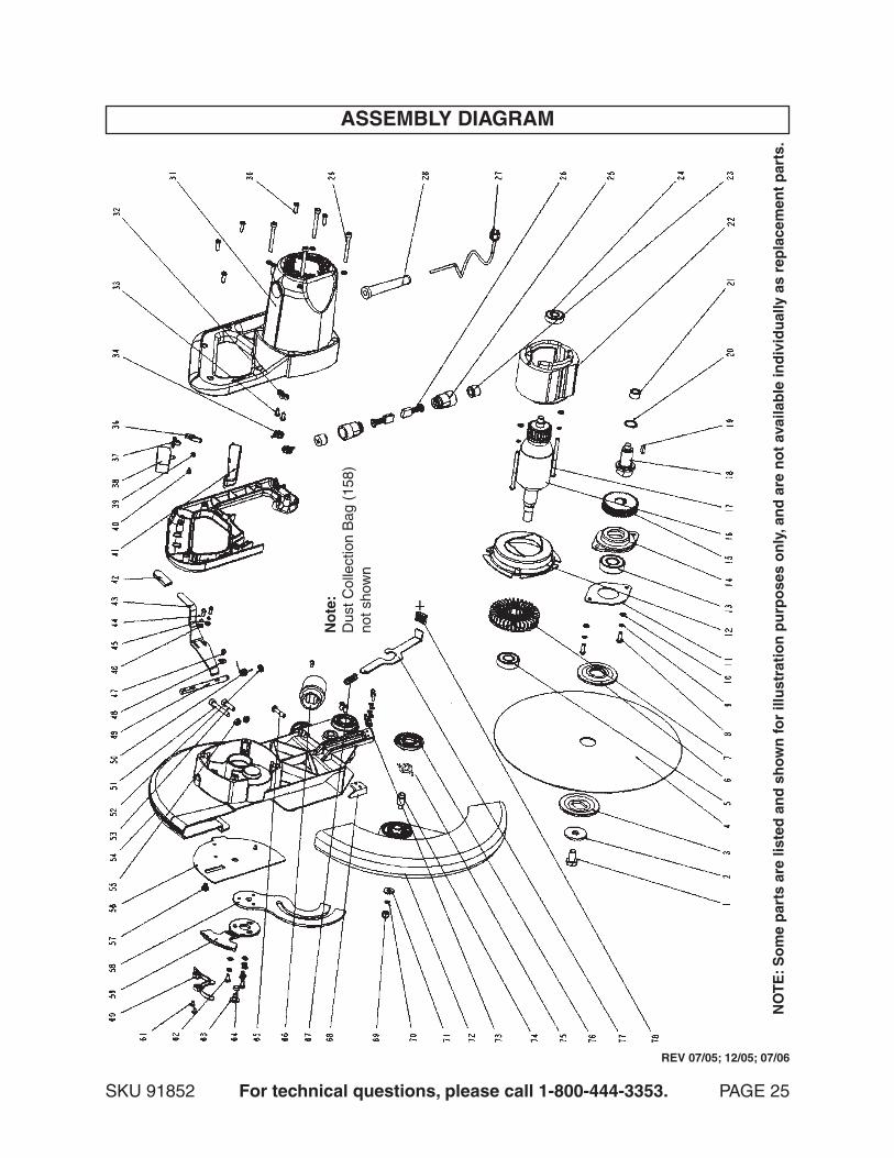
NOTE: Some parts are listed and shown for illustration purposes only, and are not available indi-vidually as replacement parts.
REV 07/06

SKU 91852 For technical questions, please call 1-800-444-3353. PAGE 24
PARTS LIST - CONTINUED
NOTE: Some parts are listed and shown for illustration purposes only, and are not available indi-vidually as replacement parts.
REV 07/05; 12/05
SKU 91852 For technical questions, please call 1-800-444-3353. PAGE 25
ASSEMBLY DIAGRAM
NO
TE
: So
me
par
ts a
re li
sted
an
d s
ho
wn
for
illu
stra
tio
n p
urp
ose
s o
nly
, an
d a
re n
ot
avai
lab
le in
div
idu
ally
as
rep
lace
men
t p
arts
.
No
te:
Dus
t Col
lect
ion
Bag
(15
8)no
t sho
wn
REV 07/05; 12/05; 07/06
SKU 91852 For technical questions, please call 1-800-444-3353. PAGE 26
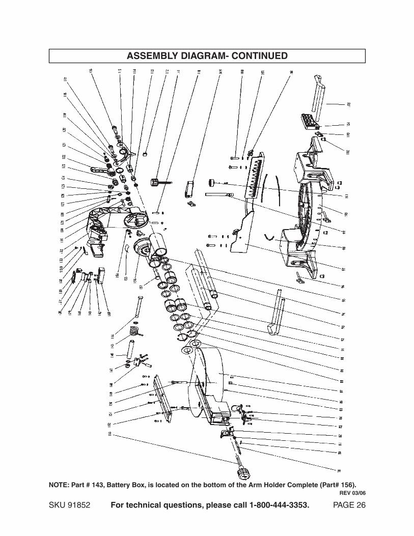
ASSEMBLY DIAGRAM- CONTINUED
NOTE: Part # 143, Battery Box, is located on the bottom of the Arm Holder Complete (Part# 156). REV 03/06
159
, I need sku 65619 (index 120304) English Wheel

SKU 91852 For technical questions, please call 1-800-444-3353. PAGE 27
LIMITED 1 YEAR / 90 DAY WARRANTYHarbor Freight Tools Co. makes every effort to assure that its products meet high
quality and durability standards, and warrants to the original purchaser that for a period of ninety days from date of purchase that the engine/motor, the belts (if so equipped), and the blades (if so equipped) are free of defects in materials and workmanship. Har-bor Freight Tools also warrants to the original purchaser, for a period of one year from date of purchase, that all other parts and components of the product are free from defects in materials and workmanship (90 days if used by a professional contractor or if used as rental equipment). This warranty does not apply to damage due directly or indirectly, to misuse, abuse, negligence or accidents, repairs or alterations outside our facilities, normal wear and tear, or to lack of maintenance. We shall in no event be liable for death, injuries to persons or property, or for incidental, contingent, special or con-sequential damages arising from the use of our product. Some states do not allow the exclusion or limitation of incidental or consequential damages, so the above limitation of exclusion may not apply to you. THIS WARRANTY IS EXPRESSLY IN LIEU OF ALL OTHER WARRANTIES, EXPRESS OR IMPLIED, INCLUDING THE WARRANTIES OF MERCHANTABILITY AND FITNESS.
To take advantage of this warranty, the product or part must be returned to us with transportation charges prepaid. Proof of purchase date and an explanation of the complaint must accompany the merchandise. If our inspection verifies the defect, we will either repair or replace the product at our election or we may elect to refund the purchase price if we cannot readily and quickly provide you with a replacement. We will return repaired products at our expense, but if we determine there is no defect, or that the defect resulted from causes not within the scope of our warranty, then you must bear the cost of returning the product.
This warranty gives you specific legal rights and you may also have other rights which vary from state to state.
3491 Mission Oaks Blvd. • PO Box 6009 • Camarillo, CA 93011 • (800) 444-3353