Embed Size (px)
Citation preview

7I76/7I76D STEP/DIR PLUS I/O DAUGHTERCARD
V1.23


iii
Table of Contents
GENERAL . . . . . . . . . . . . . . . . . . . . . . . . . . . . . . . . . . . . . . . . . . . . . . . . . . . . . . . . . . 1
DESCRIPTION . . . . . . . . . . . . . . . . . . . . . . . . . . . . . . . . . . . . . . . . . . . . . . . . . 1
HARDWARE CONFIGURATION . . . . . . . . . . . . . . . . . . . . . . . . . . . . . . . . . . . . . . . . 2
GENERAL . . . . . . . . . . . . . . . . . . . . . . . . . . . . . . . . . . . . . . . . . . . . . . . . . . . . 2VIN POWER SOURCE . . . . . . . . . . . . . . . . . . . . . . . . . . . . . . . . . . . . . . . . . . . 2CABLE 5V POWER . . . . . . . . . . . . . . . . . . . . . . . . . . . . . . . . . . . . . . . . . . . . . 2SETUP/OPERATE MODE . . . . . . . . . . . . . . . . . . . . . . . . . . . . . . . . . . . . . . . . 2ENCODER INPUT MODE . . . . . . . . . . . . . . . . . . . . . . . . . . . . . . . . . . . . . . . . 2
CONNECTORS . . . . . . . . . . . . . . . . . . . . . . . . . . . . . . . . . . . . . . . . . . . . . . . . . . . . . . 37I76 CONNECTOR LOCATIONS AND DEFAULT JUMPER POSITIONS . . . . 3HOST INTERFACE CONNECTOR . . . . . . . . . . . . . . . . . . . . . . . . . . . . . . . . . . 4TB2 STEP AND DIR CONNECTOR . . . . . . . . . . . . . . . . . . . . . . . . . . . . . . . . . 5
TB3 STEP/DIR, ENCODER AND RS-422 CONNECTOR . . . . . . . . . . . . . . . . . 6TB4 SPINDLE CONNECTOR . . . . . . . . . . . . . . . . . . . . . . . . . . . . . . . . . . . . . . 7FIELD INPUT/OUTPUT CONNECTORS . . . . . . . . . . . . . . . . . . . . . . . . . . . . . 8
TB6 PINOUT . . . . . . . . . . . . . . . . . . . . . . . . . . . . . . . . . . . . . . . . . . . . . 8TB5 PINOUT . . . . . . . . . . . . . . . . . . . . . . . . . . . . . . . . . . . . . . . . . . . . . 9
FIELD POWER CONNECTOR . . . . . . . . . . . . . . . . . . . . . . . . . . . . . . . . . . . . 10
OPERATION . . . . . . . . . . . . . . . . . . . . . . . . . . . . . . . . . . . . . . . . . . . . . . . . . . . . . . . 11HOST INTERFACE . . . . . . . . . . . . . . . . . . . . . . . . . . . . . . . . . . . . . . . . . . . . 11STEP/DIR INTERFACE . . . . . . . . . . . . . . . . . . . . . . . . . . . . . . . . . . . . . . . . . 11RS-422 INTERFACE . . . . . . . . . . . . . . . . . . . . . . . . . . . . . . . . . . . . . . . . . . . 11ENCODER INTERFACE . . . . . . . . . . . . . . . . . . . . . . . . . . . . . . . . . . . . . . . . 12SPINDLE INTERFACE . . . . . . . . . . . . . . . . . . . . . . . . . . . . . . . . . . . . . . . . . . 12SPINDLE ISOLATED OUTPUTS . . . . . . . . . . . . . . . . . . . . . . . . . . . . . . . . . . 12STATUS LEDS . . . . . . . . . . . . . . . . . . . . . . . . . . . . . . . . . . . . . . . . . . . . . . . . 12

iv
Table of ContentsOPERATION
FIELD I/O . . . . . . . . . . . . . . . . . . . . . . . . . . . . . . . . . . . . . . . . . . . . . . . . . . . . 13FIELD AND VIN POWER SUPPLY . . . . . . . . . . . . . . . . . . . . . . . . . . . . . . . . 13FIELD OUTPUT CHARACTERISTICS . . . . . . . . . . . . . . . . . . . . . . . . . . . . . . 13
SOURCING VS SINKING OUTPUTS . . . . . . . . . . . . . . . . . . . . . . . . . 13SHORT CIRCUIT PROTECTION . . . . . . . . . . . . . . . . . . . . . . . . . . . . . 13OVERTEMPERATURE PROTECTION . . . . . . . . . . . . . . . . . . . . . . . . 13MAXIMUM PER CHIP CURRENT . . . . . . . . . . . . . . . . . . . . . . . . . . . . 14VOLTAGE CLAMPS . . . . . . . . . . . . . . . . . . . . . . . . . . . . . . . . . . . . . . 14
FIELD INPUT CHARACTERISTICS . . . . . . . . . . . . . . . . . . . . . . . . . . . . . . . . 14WHY SINKING INPUTS . . . . . . . . . . . . . . . . . . . . . . . . . . . . . . . . . . . . 14ANALOG INPUTS . . . . . . . . . . . . . . . . . . . . . . . . . . . . . . . . . . . . . . . . 14FIELD VOLTAGE MONITORING . . . . . . . . . . . . . . . . . . . . . . . . . . . . . 14
WATCHDOG AND FAULTS . . . . . . . . . . . . . . . . . . . . . . . . . . . . . . . . . . . . . . 15FIELD I/O PARAMETERS . . . . . . . . . . . . . . . . . . . . . . . . . . . . . . . . . . . . . . . 15NON-VOLATILE FIELD I/O PARAMETERS . . . . . . . . . . . . . . . . . . . . . . . . . . 16
OPERATE MODE BAUD RATE . . . . . . . . . . . . . . . . . . . . . . . . . . . . . . 16WATCHDOG TIMEOUT . . . . . . . . . . . . . . . . . . . . . . . . . . . . . . . . . . . . 16
RPD, WPD, AND UFLBP . . . . . . . . . . . . . . . . . . . . . . . . . . . . . . . . . . . . . . . . 17SOFTWARE PROCESS DATA MODES . . . . . . . . . . . . . . . . . . . . . . . . . . . . 18

v
Table of ContentsREFERENCE INFORMATION
SSLBP . . . . . . . . . . . . . . . . . . . . . . . . . . . . . . . . . . . . . . . . . . . . . . . . . . . . . . 19GENERAL . . . . . . . . . . . . . . . . . . . . . . . . . . . . . . . . . . . . . . . . . . . . . . 19REGISTER MAP . . . . . . . . . . . . . . . . . . . . . . . . . . . . . . . . . . . . . . . . . 19PROCESS INTERFACE REGISTERS . . . . . . . . . . . . . . . . . . . . . . . . . 19COMMAND REGISTER . . . . . . . . . . . . . . . . . . . . . . . . . . . . . . . . . . . . 20COMMAND REGISTER WRITE IGNORE . . . . . . . . . . . . . . . . . . . . . . 20DATA REGISTER . . . . . . . . . . . . . . . . . . . . . . . . . . . . . . . . . . . . . . . . 21LOCAL READ OPERATIONS . . . . . . . . . . . . . . . . . . . . . . . . . . . . . . . 21LOCAL WRITE OPERATIONS . . . . . . . . . . . . . . . . . . . . . . . . . . . . . . 21LOCAL PARAMETERS . . . . . . . . . . . . . . . . . . . . . . . . . . . . . . . . . . . . 22NORMAL START . . . . . . . . . . . . . . . . . . . . . . . . . . . . . . . . . . . . . . . . . 23STOP ALL . . . . . . . . . . . . . . . . . . . . . . . . . . . . . . . . . . . . . . . . . . . . . . 24STOP INDIVIDUAL CHANNELS . . . . . . . . . . . . . . . . . . . . . . . . . . . . . 24DOIT . . . . . . . . . . . . . . . . . . . . . . . . . . . . . . . . . . . . . . . . . . . . . . . . . . 24PER CHANNEL INTERFACE DATA REGISTERS . . . . . . . . . . . . . . . . 25PER CHANNEL CONTROL AND STATUS REGISTERS . . . . . . . . . . 25REMOTE MODES . . . . . . . . . . . . . . . . . . . . . . . . . . . . . . . . . . . . . . . . 25INTERFACE AND CS REGISTER CONTENTS AT START . . . . . . . . . 25CS REGISTER AFTER START . . . . . . . . . . . . . . . . . . . . . . . . . . . . . . 27CS REGISTER AFTER DOIT . . . . . . . . . . . . . . . . . . . . . . . . . . . . . . . . 27PROCESS DATA DISCOVERY . . . . . . . . . . . . . . . . . . . . . . . . . . . . . . 28PROCESS TABLE OF CONTENTS . . . . . . . . . . . . . . . . . . . . . . . . . . . 28PROCESS DATA DESCRIPTOR . . . . . . . . . . . . . . . . . . . . . . . . . . . . . 29PROCESS DATA DESCRIPTOR FIELDS . . . . . . . . . . . . . . . . . . . . . . 29RECORD_TYPE . . . . . . . . . . . . . . . . . . . . . . . . . . . . . . . . . . . . . . . . . 29DATA_LENGTH . . . . . . . . . . . . . . . . . . . . . . . . . . . . . . . . . . . . . . . . . . 29DATA_TYPE . . . . . . . . . . . . . . . . . . . . . . . . . . . . . . . . . . . . . . . . . . . . 30DATA_DIRECTION . . . . . . . . . . . . . . . . . . . . . . . . . . . . . . . . . . . . . . . 30PARAMETER_MIN . . . . . . . . . . . . . . . . . . . . . . . . . . . . . . . . . . . . . . . 30PARAMETER_MAX . . . . . . . . . . . . . . . . . . . . . . . . . . . . . . . . . . . . . . . 30UNIT_STRING . . . . . . . . . . . . . . . . . . . . . . . . . . . . . . . . . . . . . . . . . . . 31NAME_STRING . . . . . . . . . . . . . . . . . . . . . . . . . . . . . . . . . . . . . . . . . . 31NUMERIC PROCESS DATA SCALING . . . . . . . . . . . . . . . . . . . . . . . . 31MODE DESCRIPTOR . . . . . . . . . . . . . . . . . . . . . . . . . . . . . . . . . . . . . 31MODE TYPES . . . . . . . . . . . . . . . . . . . . . . . . . . . . . . . . . . . . . . . . . . . 31PROCESS ELEMENT PACKING AND UNPACKING . . . . . . . . . . . . . 327I76 SPECIFIC PROCESS DATA EXAMPLE . . . . . . . . . . . . . . . . . . . 33NORMAL MODE OPERATION . . . . . . . . . . . . . . . . . . . . . . . . . . . . . . 35SETUP START . . . . . . . . . . . . . . . . . . . . . . . . . . . . . . . . . . . . . . . . . . 36SETUP MODE OPERATION . . . . . . . . . . . . . . . . . . . . . . . . . . . . . . . . 36REMOTE READ EXAMPLE . . . . . . . . . . . . . . . . . . . . . . . . . . . . . . . . . 36REMOTE WRITE EXAMPLE . . . . . . . . . . . . . . . . . . . . . . . . . . . . . . . . 37DISCOVERY SEQUENCE . . . . . . . . . . . . . . . . . . . . . . . . . . . . . . . . . . 38

vi
Table of ContentsREFERENCE INFORMATION . . . . . . . . . . . . . . . . . . . . . . . . . . . . . . . . . . . . . . . 41
LBP . . . . . . . . . . . . . . . . . . . . . . . . . . . . . . . . . . . . . . . . . . . . . . . . . . . . . . . . 41LBP DATA READ/WRITEWCOMMAND . . . . . . . . . . . . . . . . . . . . . . . 41EXAMPLE COMMANDS . . . . . . . . . . . . . . . . . . . . . . . . . . . . . . . . . . . 42LOCAL LBP COMMANDS . . . . . . . . . . . . . . . . . . . . . . . . . . . . . . . . . . 43LOCAL LBP READ COMMANDS . . . . . . . . . . . . . . . . . . . . . . . . . . . . . 43LOCAL LBP WRITE COMMANDS . . . . . . . . . . . . . . . . . . . . . . . . . . . . 45RPC COMMANDS . . . . . . . . . . . . . . . . . . . . . . . . . . . . . . . . . . . . . . . . 45EXAMPLE RPC COMMAND LIST . . . . . . . . . . . . . . . . . . . . . . . . . . . . 47SPECIAL RPCS . . . . . . . . . . . . . . . . . . . . . . . . . . . . . . . . . . . . . . . . . . 48CRC . . . . . . . . . . . . . . . . . . . . . . . . . . . . . . . . . . . . . . . . . . . . . . . . . . . 48FRAMING . . . . . . . . . . . . . . . . . . . . . . . . . . . . . . . . . . . . . . . . . . . . . . 48SSERIAL REMOTE RPCS . . . . . . . . . . . . . . . . . . . . . . . . . . . . . . . . . . 49
SPECIFICATIONS . . . . . . . . . . . . . . . . . . . . . . . . . . . . . . . . . . . . . . . . . . . . . 50DRAWINGS . . . . . . . . . . . . . . . . . . . . . . . . . . . . . . . . . . . . . . . . . . . . . . . . . . 52

7I76 1
GENERAL
DESCRIPTION
The 7I76/7I76D is daughtercard/breakout board for use with MESA's 25 pin I/OFPGA cards like the 5I25. The 7I76/7I76D is designed for interfacing up to 5 Axis of step&dir step motor or servo motor drives and also provides a spindle encoder interface,isolated analog spindle speed control and 48 isolated I/O points for general purpose fieldI/O use.
All step and direction outputs are buffered 5V signals that can drive 24 mA. Alloutputs support differential mode to reduce susceptibility to noise. An isolated analogspindle voltage with direction and enable outputs is provided for spindle control as is asingle spindle encoder channel with TTL or differential inputs.
48 points of isolated field I/O are provided for general control use including limitswitch and control panel inputs, coolant enable and tool changer control outputs. IsolatedI/O includes 32 sinking inputs and 16 sourcing (7I76) or sinking (7I76D) outputs. Inputs cansense 5V to 32V signals and the outputs can switch 5V through 32V signals. Maximumoutput load is 300 mA. Outputs are short circuit protected. Field I/O is powered by anisolated 8-32V field power source.
One RS-422 interface is provided for I/O expansion via a serial I/O daughtercard.All field wiring is terminated in pluggable 3.5 mm screw terminal blocks.
Unless the 7I76D is mentioned specifically, all information in this manual applies toboth the 7I76 and 7I76D

7I76 2
HARDWARE CONFIGURATION
GENERAL
Hardware setup jumper positions assume that the 7I76 card is oriented in an uprightposition, that is, with the host interface DB25 connector pointing towards the left.
VIN POWER SOURCE
The isolated field I/O on the 7I76 runs from a switching power supply that can bepowered by field power or a separate supply (VIN) with ground common with field power.Normally the 7I76's VIN will be powered with field power. An on card jumper, W1 allowsVIN to be connected to field power. If you wish to use a single power supply for the 7I76sfield outputs and field logic power, W1 should be placed in the left hand position. Thisconnects field power to VIN. If you wish to use a separate supply for VIN, W1 Should beplaced in the right hand position.
CABLE 5V POWER
The 7I76 can get its 5V encoder, step/dir and serial interface power from the hostinterface card if desired. W2 determines if the 7I76 gets this 5V power from the host FPGAcard. If W2 is in the left hand position, host cable power is used. If W2 is in the right handposition, 5V power must be supplied to the 7I76 via TB3. This option must be set to matchthe cable power option of the host FPGA card. If the FPGA card supplies 5V, W2 must bein the left hand position. If the FPGA card does not supply 5V, W2 must be in the righthand position. Never apply external 5V power to the 7I76's TB3 con nector when W2is in the left hand position or you may damage the 7I76, FPGA card, PC, orconnecting cable.
SETUP/OPERATE MODE
The 7I76 can run in setup mode or operate mode. In setup mode, the serialinterface baud rate is fixed at 115.2K baud. In the operate mode, the baud rate is set to2.5M baud (default). Setup mode enables a normal PC to communicate with the 7I76 forsetup purposes. W3 controls the setup/operate mode selection.T W3 must be in the"operate" mode for normal operation.
W3 MODE BAUD RATE
LEFT Operate mode 2.5M baud (default, can be changed)
RIGHT Setup Mode 115.2K baud (fixed)
ENCODER INPUT MODE
The 7I76s high speed encoder input can be programmed for differential or singleended mode operation. W4, W5 and W6 set the encoder input mode. When W4,W5,andW6 are in the right hand position, the encoder input is mode is differential. When W4,W5,and W6 are in the left hand position, the encoder input mode is single ended or "TTL".

7I76 3
CONNECTORS
7I76 CONNECTOR LOCATIONS AND DEFAULT JUMPER POSITIONS

7I76 4
CONNECTORS
P1 HOST INTERFACE CONNECTOR
P1 is the DB25F connector on the 7I76 that connects to the FPGA card. Actual pinfunctions depend on FPGA configuration but signal directions must be observed.
DB25 PIN GPIO FUNCT DIR DB25 PIN GPIO FUNC DIR
1 IO0 DIR0 OUT 14 IO1 STEP0 OUT
2 IO2 DIR1 OUT 15 IO3 STEP1 OUT
3 IO4 DIR2 OUT 16 IO5 STEP2 OUT
4 IO6 DIR3 OUT 17 IO7 STEP3 OUT
5 IO8 DIR4 OUT 18 GND
6 IO9 STEP4 OUT 19 GND
7 IO10 SS0TX OUT 20 GND
8 IO11 SS0RX IN 21 GND
9 IO12 SS1TX OUT 22 GND or 5V
10 IO13 SS1RX IN 23 GND or 5V
11 IO14 ENCI IN 24 GND or 5V
12 IO15 ENCB IN 25 GND or 5V
13 IO16 ENCA IN
Notes
1. If jumper W2 is is the left hand position, pins 22 through 25 are 5V, if W2 is in the righthand position, Pins 22 through 25 are GND.
2. GPIO pins are for first FPGA connector, next connector series begins at GPIO17
3. Signal directions are relative to FPGA card, that is, an ‘OUT’ signal is an output from theFPGA card that drives the 7I76. Conversely an ‘IN’ signal is a FPGA input that is drivenby the 7I76.

7I76 5
CONNECTORS
TB2 STEP AND DIR CONNECTOR
TB2 is the 7I76s main step and direction output connector. Both polarities of stepand direction signals are provided. Each channel on the interface uses 6 pins. TB2 is a 3.5MM pluggable terminal block with supplied removable screw terminal plugs.
TB2 CONNECTOR PINOUTTB2 PIN SIGNAL TB2 PIN SIGNAL
1 GND 13 GND
2 STEP0- 14 STEP2-
3 STEP0+ 15 STEP2+
4 DIR0- 16 DIR2-
5 DIR0+ 17 DIR2+
6 +5VP 18 +5VP
7 GND 19 GND
8 STEP1- 20 STEP3-
9 STEP1+ 21 STEP3+
10 DIR1- 22 DIR3-
11 DIR1+ 23 DIR3+
12 +5VP 24 +5VP
Note: 5VP pins are PTC short circuit protected 5V output pins for field wiring.

7I76 6
CONNECTORS
TB3 STEP/DIR, ENCODER AND RS-422 CONNECTOR
TB3 has a mix of signals including step/dir channel 4, an encoder interface, a RS-422 interface, and 5V power supply terminals TB3 is a 24 terminal 3.5 MM pluggableterminal block with supplied removable screw terminal plugs.
TB3 CONNECTOR PINOUTTB3 PIN SIGNAL TB3 PIN SIGNAL
1 GND 13 IDX+
2 STEP4- 14 IDX-
3 STEP4+ 15 GND
4 DIR4- 16 RS-422 RX+
5 DIR4+ 17 RS-422 RX-
6 +5VP 18 RS-422 TX+
7 ENCA+ 19 RS-422 TX-
8 ENCA- 20 +5VP
9 GND 21 +5V 5V supply power
10 ENCB+ 22 +5V 5V supply power
11 ENCB- 23 GND
12 +5VP 24 GND
Note: 5VP pins are PTC short circuit protected 5V output pins for field wiring.

7I76 7
CONNECTORS
TB4 SPINDLE CONNECTOR
TB4 is the spindle drive interface with isolated analog output and control signals fora spindle interface.TB4 is a 8 terminal 3.5 MM pluggable terminal block with suppliedremovable screw terminal plugs.
TB4 PINOUTTB4 PIN SIGNAL
1 SPINDLE-
2 SPINDLE OUT
3 SPINDLE+
4 NC
5 SPINDLE ENA-
6 SPINDLE ENA+
7 SPINDLE DIR-
8 SPINDLE DIR+

7I76 8
CONNECTORS
FIELD INPUT/OUTPUT CONNECTORS
Terminal blocks TB6 and TB5 are the 7I76s field input and output terminals. Inputs0 through 15 and outputs 0 through 7 are terminated at TB6. Inputs 16 through 31 andoutputs 8 through 15 are terminated at TB5. TB6 and TB5 are 3.5 MM pluggable terminalblock with supplied removable screw terminal plugs. Pin one is at the bottom edge of the7I76 card.
TB6 CONNECTOR PINOUTTB6 PIN I/O TB6 PIN I/O
1 INPUT0 13 INPUT12
2 INPUT1 14 INPUT13
3 INPUT2 15 INPUT14
4 INPUT3 16 INPUT15
5 INPUT4 17 OUTPUT0
6 INPUT5 18 OUTPUT1
7 INPUT6 19 OUTPUT2
8 INPUT7 20 OUTPUT3
9 INPUT8 21 OUTPUT4
10 INPUT9 22 OUTPUT5
11 INPUT10 23 OUTPUT6
12 INPUT11 24 OUTPUT7

7I76 9
CONNECTORS
FIELD INPUT/OUTPUT CONNECTORS
TB5 CONNECTOR PINOUTTB5 PIN OUTPUT TB5 PIN OUTPUT
1 INPUT16 13 INPUT28
2 INPUT17 14 INPUT29
3 INPUT18 15 INPUT30
4 INPUT19 16 INPUT31
5 INPUT20 17 OUTPUT8
6 INPUT21 18 OUTPUT9
7 INPUT22 19 OUTPUT10
8 INPUT23 20 OUTPUT11
9 INPUT24 21 OUTPUT12
10 INPUT25 22 OUTPUT13
11 INPUT26 23 OUTPUT14
12 INPUT27 24 OUTPUT15

7I76 10
CONNECTORS
FIELD POWER CONNECTOR
TB1 is the 7I76s field power connector. TB1 pinout is as follows:
TB1 PIN SIGNAL FUNCTION
1 VFIELD FIELD POWER 8-32V (Bottom pin)
2 VFIELD FIELD POWER 8-32V
3 VFIELD FIELD POWER 8-32V
4 VFIELD FIELD POWER 8-32V
5 VIN LOGIC POWER 8-32V
6 NC
7 NC
8 GROUND VIN, VFIELD, COMMON (Top pin)
Note: When W1 is in the default left hand position, VIN is connected to VFIELD, so onlyVFIELD need be supplied to the 7I76 to power its field IO.

7I76 11
OPERATION
HOST INTERFACE
The 7I76 is intended to operate with a FPGA card with parallel port pinout like theMesa 5I25 or 6I25. The FPGA card supports the step/dir, encoder, and smart serialinterface used by the field I/O and spindle interface and expansion RS-422 port. The FPGAcard can also supply 5V power to the 7I76.
STEP/DIR INTERFACE
The 7I76 provides five channels of step/dir interface with buffered 5V differentialsignal pairs. Each differential pair consists of two complementary 5V outputs. Thedifferential signals allows reliable signal transmission in noisy environments and candirectly interface with RS-422 line receivers. Step motor drives with single ended inputsconnect to just one of the STEP and DIR signal outputs, that is either the STEP+/DIR+ orSTEP-/DIR- signals, with the unused signals left unconnected at the 7I76. The inputcommon signal on drives with single ended inputs connects to the 7I76s GND or 5VP pinsdepending on the drive type.
RS-422 INTERFACE
The 7I76 has one RS-422 interface available on TB3. This interface is intended forI/O expansion with Mesa SSERIAL devices. The easiest way to make a cable forinterfacing the 7I76 to these devices is to take a standard CAT5 or CAT6 cable, cut it inhalf, and wire the individual wires to the 7I76 screw terminals. The following chart gives theCAT5 to 7I76 screw terminal connections (EIA/TIA 568B colors shown):
TB3 PIN SIGNAL DIRECTION CAT5 PINS CAT5 568B COLOR
15 GND FROM 7I76 4,5 BLUE, BLUE / WHITE
16 RX+ TO 7I76 6 GREEN
17 RX- TO 7I76 3 GREEN / WHITE
18 TX+ FROM 7I76 2 ORANGE
19 TX- FROM 7I76 1 ORANGE / WHITE
20 +5V FROM 7I76 7,8 BROWN / WHITE,BROWN
Note: The 6 pin terminal block requires the +5V (brown and brown/white) and ground (blueand blue/white) pairs to be terminated in single screw terminal positions.

7I76 12
OPERATION
ENCODER INTERFACE
The 7I76 provide a one channel encoder interface with index. This is intended asa spindle encoder but can be used for other purposes. The encoder input can beprogrammed for differential or single ended encoders. The encoder interface also providesshort circuit protected 5V power to the encoder. When used with single ended encoders,the ENCA+, ENCB+ and IDX+ signals are wired to the encoder and the ENCA-,ENCB-,and IDX- terminal left unconnected.
SPINDLE INTERFACE
The 7I76 provides one analog output for spindle control. The analog output is aisolated potentiometer replacement type device. It functions like a potentiometer withSPINDLE + being one end of the potentiometer, SPINDLEOUT being the wiper andSPINDLE- being the other end. The voltage on SPINDLEOUT can be set to any voltagebetween SPINDLE- and SPINDLE+. Polarity and voltage range must always be observedfor proper operation. The voltage supplied between SPINDLE+ and SPINDLE- must bebetween 5VDC an 15VDC with SPINDLE + always being more positive than SPINDLE-.
Because the analog output is isolated, bipolar output is possible, for example withSPINDLE+ connected to 5V and SPINDLE- connected to -5V, a +-5V analog output rangeis created. In this case the spindle output must be offset so that 50% of full scale is outputwhen a 0V output is required. Note that if bipolar output is used, the output will be forcedto SPINDLE- at startup or when SPINENA is false.
SPINDLE ISOLATED OUTPUTS
The 7I76 provides 2 isolated outputs for use for spindle direction control, andspindle enable. These outputs are OPTO coupler Darlington transistors. They are allisolated from one another so can be used for pull up or pull-down individually. They willswitch a maximum of 50 mA at 0 to 100 VDC. The SPINENA output is special as it usesthe same signal that enables the analog output. When the analog output is enabled, theSPINENA OPTO output is on.
STATUS LEDS
The 7I76 has two yellow status LEDs for power monitoring, CR1 and CR2. CR1 onthe top left side of the 7I76 monitors 5V power. CR2 on the top right side of the 7I76monitors field power. Both LEDs must be illuminated for normal operation.

7I76 13
OPERATION
FIELD I/O
The 7I76 has a 32 input, 16 output isolated field I/O system to support a wide rangeof input and output devices. The isolated I/O is intended for low voltage DC controlsystems (commonly 24VDC). Inputs are sinking type. That is they sense positive inputvoltages relative to field ground. Outputs are sourcing (7I76) or sinking (7I76D) type.Sourcing outputs supply field power to field ground referred loads. Sinking outputs groundfield voltage referred loads when on.
VIN AND FIELD POWER SUPPLY
The 7I76 field I/O runs from field power supplies of 5 to 32 VDC. Field powersupplies the power to the 7I76 outputs and determines the 7I76 input thresholds. VINpower runs the field I/O processor and normally is connected to field power. VIN must begreater than 8V for proper operation. This means VIN must come from a separate sourceif 5V field voltage is used. Power consumption is approximately 600 mW or 25 mA at 24V.VIN power must be present for the 7I76 field I/O to be detected and operate. Field voltagesthat are too high or too low will cause faults.
FIELD OUTPUT CHARACTERISTICS
The 7I76 (no D) field outputs are high side or sourcing type drivers, that is theysource positive voltage to a ground referred load. For example with a standard 24V fieldpower, +24V connects to the 7I76s field power input (on TB1) and the outputs on TB5 andTB6 now source +24V power to loads. All 7I76 loads will have one side returned to groundor the negative lead of the 24V supply. The 7I76s outputs can drive loads of up to 350 mA.
The 7I76D field outputs are low side or sinking type drivers, that is they connect theload side of a field voltage referred load to field common.
SOURCING VS SINKING OUTPUTSThe advantage of sourcing type field wiring is that it is less likely to cause
inadvertent device actuation from the most likely type of field wiring problem which is ashort to ground. The advantage of sinking drivers is compatibility with existing hardwareon retrofits and the capability of using mixed output voltages.
SHORT CIRCUIT PROTECTIONThe 7I76s outputs have short circuit protection and will turn off if short circuit current
exceeds approximately 800 mA. The 7I76 firmware will detect this condition, disable theaffected output and indicate a fault.
OVERTEMPERATURE PROTECTIONThe output driver chips detect over temperature conditions. If the 7I76 detects a
driver chip with a over temperature warning flag asserted, it will disable the affected chipand indicate a fault.

7I76 14
OPERATION
FIELD OUTPUT CHARACTERISTICS
MAXIMUM PER CHIP CURRENTBecause of thermal limitations there is a maximum per driver chip total current of
1.4 amps continuous. Each driver chip connects to 8 sequential outputs. If this limit isexceeded, the driver chip may go into thermal shutdown.
VOLTAGE CLAMPSThe output driver chips used on the 7I76 have built in Zener diode clamps to clamp
inductive turn-off (fly-back) spikes. This means that flyback diodes are not normallyrequired on small (less than 60 mA) inductive loads. If high current inductive loads areswitched or inductive loads are switched at high fr equencies, they must haveflyback diodes to limit power dissipation in the 7I 76's driver chips.
FIELD INPUT CHARACTERISTICS
The 7I76 field inputs have a nominal input resistance of 20K Ohms to field powerground. 7I76 inputs sense positive input voltages above a preset threshold. For bestgeneral purpose use, default input threshold is 50% of the field power supply voltage with10% hysteresis. That is with a 24V field voltage an input must be brought to 60% of 24V= 14.4V to be sensed as high and then brought to 40% of 24V = 9.6V to be sensed as low.These accurate thresholds and hysteresis allow high speed field signal detection whilemaintaining excellent noise immunity.
WHY SINKING INPUTS7I76 field inputs are of the sinking type. That is, external power must be applied to
the input to register as activated. This mode was chosen so that accidental grounding ofan input will not register as an activated input.
It is suggested that inputs like limit switches use normally closed switches with oneswitch leg connected to field power and the other to the 7I76 input pin, so the normalmachine state (not at limits) is to have the inputs activated. This way, a open switch wireor wire shorted to ground will cause a detectable machine fault.
ANALOG INPUTSAll field input pins are capable of reading the input voltage. These are not highly
accurate or high resolution but can be useful for things like potentiometer inputs. Inputresolution is 8 bits and input full scale value is 36.3V. Accuracy is +-5%. Software processdata modes 1 and 2 allow reading the analog voltage on inputs 0 through 3, in addition tothe 32 digital bit inputs.
FIELD VOLTAGE MONITORINGThe 7I76 monitors the field voltage and can send this information to the host in
some modes. If separate VIN is supplied to the 7I76, the 7I76 can report loss of fieldvoltage to the host.

7I76 15
OPERATION
FIELD I/O WATCHDOG AND FAULTS
The 7I76 has a watchdog timer that will set all set a fault flag if host communicationdoes not occur at a minimum rate. Default watchdog time is 50 mS which means if notaccessed at a greater than 20 Hz rate, the watchdog will bite and disable the outputs.
When a fault flag is set, outputs can not longer be set and the host must first clearthe fault before normal operation can continue. This is also the 7I76s startup condition,meaning the host must first clear the fault before starting normal operation. This isnormally handled by SSLBP.
FIELD I/O PARAMETERS
The 7I76 has several user settable parameters, but normally only a very few needbe changed in normal operation.
PARAMETER TYPE FUNCTION
NVBAUDRATE UINT Sets operate mode baudrate
NVUNITNUMBER ULONG Non-volatile unit number
UNITNUMBER ULONG Working unit number
NVWATCHDOGTIME UINT Non-volatile watchdog time in mS
WATCHDOGTIME UINT Working watchdog time in ms
OUTPUT UINT 16 bits of output data
INPUT ULONG 32 bits of input data
FAULT UINT 7I76 fault register
STATUS UINT 7I76 status register

7I76 16
OPERATION
NON-VOLATILE FIELD I/O PARAMETERS
All non volatile parameters start with the letters NV. Non-volatile parameters arestored permanently in the processors EEPROM and are copied to the volatile workingparameters at power-up. Because of this, non-volatile parameters only take affect after a7I76 power cycle.
OPERATE MODE BAUD RATEThe operate mode baud rate default is 2.5 MBaud. This should not be changed
unless needed for non-standard applications. Baud rates are selected by writing an indexvalue to the NVBAUDRATE parameter. The index numbers for available baud rates areas follows:
INDEX BAUD INDEX BAUD INDEX BAUD
0 9600B 1 19200B 2 38400B
3 57600B 4 115200B 5 230400B
6 460800B 7 921600B 8 1.25MB
9 2.5MB* 10 5MB 11 10MB
WATCHDOG TIMEOUTThe default watchdog period is 50 mS but can be set to different periods to suit the
application. Watchdog timeout units are mS. A watchdog timeout value of 0 will disable thewatchdog. The watch dog is a safety feature and should normally not be disabled nor setto long timeout periods unless the consequences of loss of control of outputs is notimportant. The non-volatile watchdog timeout is set via the NVWATCHDOGTIMEOUTparameter. The working watchdog timeout is set with the WATCHDOGTIME parameter.
.

7I76 17
OPERATION
RPD, WPD, AND UFLBP
The RPD, WPD, and UFLBP are command line utilities allow reading and writingvolatile and non-volatile 7I76 parameters, and updating the firmware on the 7I76 To usethese utilities on most operating systems, the 7I76 must be in the setup mode or theoperate mode baud rate must be 115200 KBaud or less
RPD, WPD, and UFLBP need environment variables preset before they will work.For Windows and 115200 baud, the following environment variables should be set:
SET BAUDRATE=115200
SET BAUDRATEMUL=1
SET PROTOCOL=LBP
SET INTERFACE=OSDEVICE
Example setting NVWATCHDOGTIMEOUT to 100 ms:
WPD NVWATCHDOGTIME 100
Note this is permanent change in the 7I76s watchdog timeout and like all non-volatile parameters, will only be applied after the 7I76 has been power cycled
Example reading 7I76 faults in Hexadecimal:
RPD FAULT H
Example of temporarily disabling watchdog and the setting every other output on:
WPD WATCHDOGTIME 0
WPD OUTPUT AAAAAAAAAAAA H
Example of updating 7I76 firmware with UFLBP
UFLBP 7I76.BIN
Note the 7I76 MUST be in setup mode for UFLBP to work properly.

7I76 18
OPERATION
SOFTWARE PROCESS DATA MODES
The 7I76 has three software selectable process data modes. These different modesselect different sets of 7I76 data to be transferred between the host and the 7I76 duringreal time process data exchanges. For high speed applications, choosing the correct modecan reduce the data transfer sizes, resulting in higher maximum update rates.
MODE 0 I/O only mode (32 bits of input data, 16 bit of output data)
MODE 1 I/O plus analog input mode (32 bits of input data, 16 bits of output data, 4analog input channels)
MODE 2 I/O plus analog input and field voltage and MPG mode (32 bits of input data,16 bits of output data, 4 analog input channels, field voltage analog in, and2 MPG encoders on inputs 16..19). Default encoder count mode is 1X tomatch normal 100 PPR MPGs. Encoder input threshold is fixed at 2.5V forcompatibility with 5V encoder outputs.

7I76 19
REFERENCE INFORMATIONNote that the following interface details presented here are not normally needed for
users, as all register level interface details are handed by the driver code. This informationis presented here for use by interface and driver developers.
SSLBP
GENERALSSLBP is a firmware option to HostMot2s SSERIAL serial interface that allows
simple communication to LBP based peripherals like the 7I76. SSERIAL is a part of theHostMot2 motion interface firmware for MESA’s Anything-I/O FPGA cards.
REGISTER MAPSSLBP has two global processor interface registers and four per channel remote
device interface registers. For more details on mapping of these registers in HostMot2memory space, see the REGMAP file that is included with the HostMot2 sourcedistribution.
PROCESSOR INTERFACE REGISTERSThere are two processor interface registers, the COMMAND register and the DATA
register. These registers allow low level communication to SSLBP’s interface processorfor issuing global commands, discovery, and debug operations.

7I76 20
REFERENCE INFORMATION
SSLBP
COMMAND REGISTERThe commands register is a 16 bit register (right justified in the 32 bit interface) with thefollowing format:
15 14 13 12 11 10 9 8 7 6 5 4 3 2 1 0
W M R D S T T T N N N N N N N N
W = BIT 15 Write bit, set high for control data write commands
M = BIT 14 ROM enable/ reset bit, set high to reset processor / download ROM
R = BIT 13 Request bit, set high for read or write command
D = BIT 12 DoIt bit, set high for DoIt commands
S = BIT 11 Start/Stop bit, actual operation depends on T:
ST = 1,0,0,0 Stop LBP interface = 0x08NN
ST = 1,0,0,1 Start LBP interface in normal mode = 0x09NN S T =1,1,1,1 Start LBP interface in setup mode
= 0x0FNN
N bits determine which channels start or do data transfer with remote device. A setbit indicates that the corresponding channel will start or do a data transfer.
A command is started when written to the command register. Command completionis signaled by the command register being cleared (to 0x0000) by the internal SSLBPfirmware. If the command register is read before the command is complete, it will reflectthe previously written command. The command register should not be written when non-zero or unpredictable behavior may result. There are two exceptions to this rule:
1. A STOP ALL command can always be written to reset the SSLBP interface.
2. Command writes with the ignore bit set can always be written (see below)
COMMAND REGISTER WRITE IGNORE The command register has a feature that any command written with the MSB (bit
31) set will be ignored. This is for compatibility with DMA driven interfaces or anyinterfaces that use a fixed address list for low level hardware access so cannot skip writes.

7I76 21
REFERENCE INFORMATION
SSLBP
DATA REGISTERSSLBP has a global 8 bit data register for debug and custom setup purposes. This
register allows access to internal SSLBP parameters. The data register is right justified inthe 32 bit Hostmot2 register.
LOCAL READ OPERATIONSThe sequence used for reading a local SSLBP variable is as follows:
1. The parameter address ORed with the Request bit (bit 13) is written to the commandregister.
2. The host polls the command register until it reads as zero.
3. The host reads the parameter byte from the data register
LOCAL WRITE OPERATIONSThe sequence used for writing a local SSLBP variable is as follows:
1. The host polls the command register until it reads as zero.
2. The host writes the data byte to the data register
3. The host writes the command register with the the parameter address Ored with boththe Request bit (bit 13) and the Write bit (bit 15)

7I76 22
REFERENCE INFORMATION
SSLBP
LOCAL PARAMETERSThere are a number of local SSLBP read only parameters that are useful for
interface software and drivers to access using the local read operations:
LOCAL PARAMETER ADDRESS DESCRIPTION
INTERFACE_TYPE 0x0000 0x12 for SSLBP
INTERFACE_WIDTH 0x0001 Data port width (8)
MAJORREV 0x0002 Major SSLBP firmware revision
MINORREV 0x0003 Minor SSLBP firmware revision
GP_INPUTS 0x0004 Number of GP input bits (0 for SSLBP)
GP_OUTPUTS 0x0005 Number of GP output bits (0 for SSLBP)
PROCESSOR_TYPE 0x0006 0xD8 for Dumb8
CHANNELS 0x0007 1 to 8 depending on configuration

7I76 23
REFERENCE INFORMATION
SSLBP
NORMAL STARTWhen the FPGA is first configured or after a STOP command, all local
communication, error and status parameters are initialized and all LBP communicationchannels are idle. A normal START command begins to establish communications withall remote LBP devices. A normal start command is issued by writing a Start bit with typebits of 0,0,1 with a bit mask of the desired channels to start in the low byte, This is 0x9NNhex where NN is the bitmask of channels to start. This command is written to thecommand register to start the selected channels.
Once a start command has been issued, all channels that are selected in the bitmask will be probed to determine if a LBP device exists. If a device exists on a channel,the SSLBP firmware will acquire the device name, and device unit number, and pointersto process data information from the remote device..
A normal start command also does a standard set of remote device setupoperations when it detects a remote device. This setup includes clearing any faults, settingremote operational mode, and setting the outputs off. If no errors have occurred and allfaults are clearable, the SSLBP firmware enters a "chatter" loop where it repeatedly sendsoutput data of all 0's. This keeps the remote devices watchdog fed while waiting for the firstDOIT command.
When the command completes (the command register is clear), the data registercan be read to determine if all selected channels have started. A 1 bit in any position in thedata register indicates that the corresponding channel has failed to start. If a channel hasfailed to start, more information about the failure can be determined by reading the CSregister of the failed channel.
Once a DOIT command has been executed, the firmware no longer "chatters" andit becomes the responsibility of the host interface to continue sending DOIT commands ata rate sufficient to feed the remote devices watchdog (faster than 20 Hz with the default50 mS watchdog timeout period). If this is not done, the remote device’s watchdog will bite,disabling its outputs and setting the fault flag. This will require a channel stop followed bya channel start to resume normal operations.

7I76 24
REFERENCE INFORMATION
SSLBP
STOP ALLA STOPALL command is issued to stop all channel communication. STOPALL
resets all channel variables and should always be issued by a driver when initializing theSSLBP interface. A STOPALL followed by a START command can be used after a faultcondition to re-establish communication with the remote LBP devices. Device discoveryis only done once when START command is issued to a STOPed SSLBP. This means thatif cabling, devices, or device hardware modes are are changed, a STOPALL commandfollowed by a START command must be issued by the host to detect the changes. ASTOPALL command is 0x0800.
STOP INDIVIDUAL CHANNELSIn addition to stopping all channels, a individual stop command can be issued. A
individual stop command include a bitmask of the channels to stop in the least significant8 bits of the command (the N bits), that is a stop channel 1 command would be 0x802. Theintended use of individual stop is per channel error recovery. It should not be used fornormal interface startup as it does not reset channel variables, that is a 0x8FF command(stop all individual channels) is not equivalent to a 0X800 (STOPALL) command.
DOITIn normal operation SSLBP is designed to send host data from the interface
registers to the remote device and request data from the remote device for presentationin the interface registers to the host. This SSLBP function is designed for high speed realtime operation. Synchronization with the host is accomplished with the DOIT command.
When the host writes a DOIT command,, all outgoing process data from the hostis sent to the remote devices and incoming process data is requested. Completion of theDOIT command is signaled by SSLBP clearing the COMMAND register. A DOIT commandis completed when al requested channel transfers have completed or timed out. After thecompletion of a successful DOIT command, the incoming process data from the remotecan be read.
A DOIT command contains the DOIT bit and an 8 bit mask in the 8 LSBs thatselects the channels that will be requested to transfer data. A DOIT should not berequested on an inactive channel, that is a channel that did not start. After DOITcommand completion the data register will contain a bit mask of channel status data. If anybit is set in the data register, it indicates a problem with the transfer (all zeros indicatesno faults or errors).
The data register contents returned after a DOIT command can be used to minimizehost access cycles by avoiding the need to read the per channel status registers. Ifdetailed fault information is desired, the CS register can be read on any channel thatshows a failed transfer.

7I76 25
REFERENCE INFORMATION
SSLBP
PER CHANNEL INTERFACE DATA REGISTERSSSLBP supports three 32 bit interface data registers per channel. These are called
interface register 0, interface register 1, and interface register 2. These are read/writeregisters with independent incoming and outgoing data. These registers are used for bothsetup/discovery data when starting a data link and process data once the link is running.When a start command is issued and has successfully completed, per channel setup datawill be available in the interface registers.
PER CHANNEL CONTROL AND STATUS REGISTERSSSLBP has a 32 bit control and status register for each channel. Like the interface
data registers, these registers are used both for data link startup information and for statuswhen the link is in operation.
REMOTE MODESSome remote devices have software selectable modes that determine the specific
data transferred for each DOIT command. These modes are selected by writing the modenumber to the most significant byte of the remote channels CSR before a START orSETUP START command is issued. A default value of 0x00000000 should be written toall CSRs if MODE is not used.
REMOTE MODE IS WRITTEN TO CSR MS BYTE BEFORE START
CS REG MODE 0 0 0.
INTERFACE AND CS REGISTER DATA AT STARTAfter a successful start command (either setup start or normal start), Interface register 0
reports the remote device’s unit number. This is the number printed on the card label. Interfaceregister 1 reports the remote device’s 4 letter name (LSB first). Interface register 2 reports theremote devices global table of contents pointer (GTOCP) and process table of contents pointer(PTOCP) for the currently selected remote device mode. The GTOCP and PTOCP will be 0x0000for devices that do not support process data discovery. Note that the setup data will be overwrittenwith process data once the first DOIT command is issued.
READ DATA FROM PER CHANNEL INTERFACE REGISTERS AFTER START
CS REG X COM_STATE STATUS LOCAL FLT.
INTERFACE 0 UNIT# BYTE 3 UNIT# BYTE 2 UNIT# BYTE 1 UNIT# BYTE 0
INTERFACE 1 NAME BYTE 3 NAME BYTE 2 NAME BYTE 1 NAME BYTE 0
INTERFACE 2 GTOCP BYTE1 GTOCP BYTE 0 PTOCP BYTE1 PTOCP BYTE 0

7I76 26
REFERENCE INFORMATION
SSLBP
CS REGISTER AFTER STARTThe CS register is used for local SSLBP, and remote LBP device status and control
information. Read access returns status information in both normal and setup mode. Innormal mode, writes to the CS register are not used. After a normal start or setup start theCS register has the following format:
Byte3 = X undefined for SSLBP versions < 29, remote fault for versions >28 (See CSREGISTER AFTER DOIT section)
Byte2 = COM_STATE Communication state code (debug only)
Byte1 = Communication status code (0x00 for OK)
Bit 7 = CommunicationNotReady
Bit 6 = NoRemoteID
Bit 5 = CommunicationError
Bit 0 = RemoteFault
Byte0 = Local Communication faults (sticky, cleared only by STOP)
Bit 7 = TooManyerrors
Bit 6 = RemoteFault
Bit 5 = SerialBreakError
Bit 4 = ExtraCharacterError
Bit 3 = TimeoutError
Bit 2 = OverrunError
Bit 1 = InvalidCookieError
Bit 0 = CRCError
7I76 27
REFERENCE INFORMATION
SSLBP
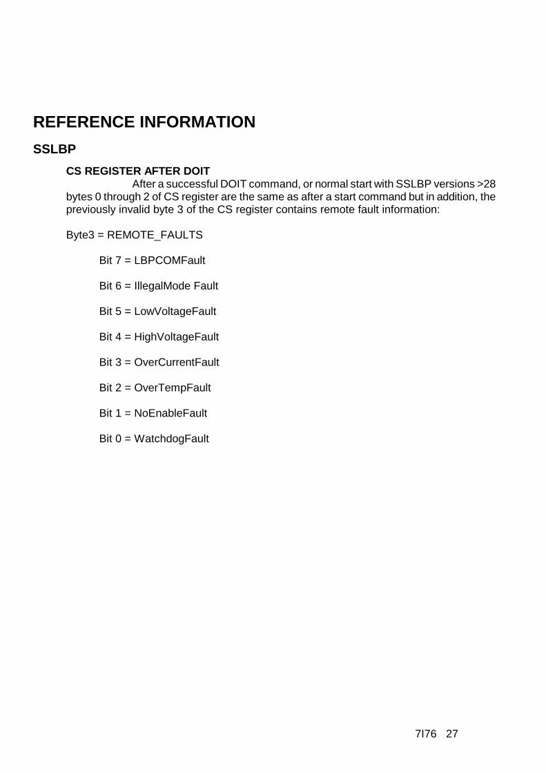
CS REGISTER AFTER DOITAfter a successful DOIT command, or normal start with SSLBP versions >28
bytes 0 through 2 of CS register are the same as after a start command but in addition, thepreviously invalid byte 3 of the CS register contains remote fault information:
Byte3 = REMOTE_FAULTS
Bit 7 = LBPCOMFault
Bit 6 = IllegalMode Fault
Bit 5 = LowVoltageFault
Bit 4 = HighVoltageFault
Bit 3 = OverCurrentFault
Bit 2 = OverTempFault
Bit 1 = NoEnableFault
Bit 0 = WatchdogFault

7I76 28
REFERENCE INFORMATION
SSLBP
PROCESS DATA DISCOVERYThe SSLBP interface provides information to allow the host to determine the name,
number, units, sizes, types, directions, and scaling of process data elements. Thisinformation is read from the remote device via a setup mode start followed by a series ofremote read operations.
Note to the bewildered: process data discovery and its complications are notneeded to access the 7I76 via SSLBP. In fact the 7I76's data can be accessed via SSLBPwith no more than a few register reads and writes The sole purpose of process datadiscovery is to allow the driver to present nicely named and formatted data to the hostwithout the driver having any built in knowledge of the remote device.
PROCESS TABLE OF CONTENTSAfter a normal start or setup start command, the PTOCP word in the low word of
interface register 2 is a pointer to the current process table of contents (PTOC) in theremote device.
If remote devices that do not support process device discovery are present, theirPTOCP will be 0, and process data organization must be inferred from the remote devicename.
Remote reads from this location will return the first entry in the PTOC. All PTOCentries are pointers with a size of 2 bytes. The end of the PTOC is marked with a 0sentinel. Each PTOC entry points to a process data descriptor. Here is an example of a5 entry PTOC (PDD is Process Data Descriptor)
ENTRY ADDRESS CONTENTS
0 PTOCP POINTER TO PDD 0
1 PTOCP+2 POINTER TO PDD 1
2 PTOCP+4 POINTER TO PDD 2
3 PTOCP+6 POINTER TO PDD 3
4 PTOCP+8 POINTER TO PDD 4
5 PTOCP+10 0x0000 (END OF TABLE)

7I76 29
REFERENCE INFORMATION
SSLBP
PROCESS DATA DESCRIPTOREach PTOC entry points to a process data descriptor or a mode descriptor. Each
process data descriptor is a record with fields for data size, data type, data direction,minimum and maximum values, the address of the process data and the unit name andprocess data name. Each process data element has a corresponding process datadescriptor record. In addition there are mode descriptor records that indicate the currenthardware and software modes of the remote device. The process data descriptor recordstructure is as follows:
FIELD NAME FIELD LENGTH DESCRIPTION
RECORD_TYPE 8 BITS RECORD TYPE = 0xA0
DATA_SIZE 8 BITS DATA SIZE IN BITS
DATA_TYPE 8 BITS DATA ELEMENT TYPE
DATA_DIRECTION 8 BITS DATA DIRECTION
PARAM_MIN 32 BITS IEEE-754 FP PARM MIN
PARAM_MAX 32 BITS IEEE-754 FP PARM MAX
PARAM_ADD 16 BITS ADDRESS OF PARM
UNIT_STRING VARIABLE NULL TERM. STRING
NAME_STRING VARIABLE NULL TERM. STRING
PROCESS DATA DESCRIPTOR FIELDS
RECORD_TYPEThe RECORD_TYPE field is a single byte at the beginning of the process data
descriptor for record typing and sanity checking. It is 0xA0 for process data records.
DATA_LENGTHThe DATA_LENGTH field is a single byte field that specifies the length of the
process data element in bits. Minimum is 1 bit, maximum is 255 bits, however currentSSLBP implementations are limited by the number of interface registers to a maximum of96 bits.

7I76 30
REFERENCE INFORMATION
SSLBP
DATA_TYPE The DATA_TYPE field is a single byte field that specifies the data type of the
process data element. Data types are as follows:
NUMBER DATA_TYPE NOTE
0x00 PAD To pad for byte alignment
0x01 BITS Packed bits, LSB is BIT 0
0x02 UNSIGNED Numeric unsigned
0x03 SIGNED Numeric twos complement LSB first
0x04 NONVOL_UNSIGNED Numeric unsigned
0x05 NONVOL_SIGNED Numeric twos complement LSB first
0x06 STREAM Continuous data stream
0x07 BOOLEAN Any length non-zero = true
DATA_DIRECTIONThe DATA_DIRECTION field is a single byte field that specifies the data direction.
Valid Data direction bytes are as follows:
0x00 INPUT (Read from remote)
0x40 BI_DIRECTIONAL (Read from and written to remote)
0X80 OUTPUT (Written to remote)
PARAMETER_MINThe PARAMETER_MIN field is a 32 bit IEEE-754 floating point number that
specifies the minimum value of the process data element. This is to allow the driver topresent data in engineering units. Not valid for non-numeric data types
PARAMETER_MAXThe PARAMETER_MAX field is a 32 bit IEEE-754 floating point number that
specifies the maximum value of the process data element. This is to allow the driver topresent data in engineering units. Not valid for non-numeric data types.

7I76 31
REFERENCE INFORMATION
SSLBP
UNIT_STRINGThe UNIT_STRING is a variable length null terminated string that specifies the units
of the process data element
NAME_STRINGThe NAME_STRING is a variable length null terminated string that begins
immediately after the UNIT_STRING. It specifies the name of the process data element.
NUMERIC PROCESS DATA SCALINGCurrently all numeric process data is simple unsigned or signed (twos complement)
binary data. The process data element PARAM_MIN and PARAM_MAX values inconjunction with the DATA_SIZE can be used to scale this numeric data.
For unsigned data, PARAM_MIN corresponds to a value of 0 and PARAM_MAXcorresponds to a value of (2 ^ DATA_SIZE) -1. Meaning scaled unsigned data isRAW_DATA*(PARAM_MAX-PARAM_MIN) / ((2 ^ DATA_SIZE) -1) +PARAM_MIN.
For signed data. PARAM_MIN corresponds the value -(2 ^ DATA_SIZE-1)-1 andPARAM_MAX corresponds the value (2 ̂ DATA_SIZE-1)-1, meaning scaled signed datais RAW_DATA (PARAM_MAX-PARAM_MIN) / ((2 ^ DATA_SIZE-1) -1) +PARAM_MIN.
MODE DESCRIPTORIn addition to the process data descriptors, the PTOC will have pointers to two mode
descriptors. These are the currently selected hardware and software modes of the remotedevice.
FIELD NAME FIELD LENGTH DESCRIPTION
RECORD_TYPE 8 BITS RECORD TYPE = 0xB0
MODE INDEX 8 BITS WHICH MODE
MODE TYPE 8 BITS MODE TYPE
UNUSED 8 BITS UNUSED
MODE_NAME_STRING VARIABLE NULL TERM. STRING
MODE TYPESCurrently there are only two mode types, HWMODE = 0x00 and SWMODE = 0x01
these correspond to hardware (EEPROM or Jumper setting )and software (dynamicallychangeable operational modes)

7I76 32
REFERENCE INFORMATION
SSLBP
PROCESS DATA ELEMENT PACKING AND UNPACKINGUltimately all process data is transferred to and from the host via the interface 0,1,2
registers.
The packing of outgoing process data elements into these interface registers andunpacking of incoming process data elements from these interface registers is done in theorder of process data descriptors listed in the PTOC. Process data elements in PTOCorder and process descriptor DATA_SIZE are packed into or unpacked from the interfaceregisters from LSB to MSB and from interface register 0 through interface register 2.
Read data and bidirectional data is unpacked from the interface registers read bythe host. Write data and bidirectional data is packed into the interface registers written bythe host.
Before a DOIT command is written to start a data transfer cycle with the remotedevice, the host must write its packed outgoing process data (OPD in table below) to theinterface registers. (The CS register not currently used for outgoing data/control so is notwritten)
HOST WRITES OUTGOING INTERFACE REGISTERS BEFORE DOIT
CS REG MODE X X X
INTERFACE 0 OPD BYTE 3 OPD BYTE 2 OPD BYTE 1 OPD BYTE 0
INTERFACE 1 OPD BYTE 7 OPD BYTE 6 OPD BYTE 5 OPD BYTE 4
INTERFACE 2 OPD BYTE 11 OPD BYTE 10 OPD BYTE 9 OPD BYTE 8

7I76 33
REFERENCE INFORMATION
SSLBP
PROCESS DATA ELEMENT PACKING AND UNPACKING
After the DOIT command has completed, the incoming process data (IPD in tablebelow) can be read along with the local and remote faults.
HOST READS INCOMING INTERFACE REGISTERS AFTER DOIT
CS REG REMOTE. FLT COM_STATE STATUS LOCAL FLT.
INTERFACE 0 IPD BYTE 3 IPD BYTE 2 IPD BYTE 1 IPD BYTE 0
INTERFACE 1 IPD BYTE 7 IPD BYTE 6 IPD BYTE 5 IPD BYTE 4
INTERFACE 2 IPD BYTE 11 IPD BYTE 10 IPD BYTE 9 IPD BYTE 8
7I76 SPECIFIC PROCESS DATA EXAMPLEProcess data is remote device dependent and also dependent on remote device
mode. The 7I76 supports 3 software modes.

7I76 34
REFERENCE INFORMATION
SSLBP
7I76 SPECIFIC PROCESS DATA EXAMPLEIn the default input/output mode the process data appears in the interface registers
in the order shown:
7I76 OUTGOING PROCESS DATA FOR MODE (1)
CS REG X X X X
INTERFACE 0 SPINOUT 15..8 SPINOUT 7..0 TB5 OUTS 15..8 TB6 OUTS 7..0
INTERFACE 1 X X SPINDIR SPINENA
INTERFACE 2 X X X X
7I76 INCOMING PROCESS DATA FOR MODE (1)
CS REG REMOTE. FLT COM_STATE STATUS LOCAL FLT.
INTERFACE 0 TB5 INS 31..24 TB5 INS 23..16 TB6 INS 15..8 TB6 INS 7..0
INTERFACE 1 ANALOG3 ANALOG2 ANALOG1 ANALOG0
INTERFACE 2 X X X X
Note that this information is just for user convenience as the process dataorganization in the interface registers can be determined by process data discovery.

7I76 35
REFERENCE INFORMATION
SSLBP
NORMAL MODE OPERATIONIn normal mode the sequence of operations for a cyclic access with write before
read is as follows:
Note steps 1 through 5 are setup operations and are only done once per session
1. Issue STOP ALL command (0x800), wait for COMMAND register clear to verify stopcommand completion.
2. Issue normal START command (0x9NN) with bitmask (NN) of channels to start.
3. Wait for COMMAND register clear to verify start command completion. (may be manymS)
4. Read data register to verify that all selected channels started (a 1 in any channelposition bit means a fault in the channel that the bit represents)
5. Read device unit number (This can only be read before DOIT has been asserted)
6. Check command register, if not clear, cycle time is too short.
(Note the command register should never be written to when not clear except to issue astop command or when written with the command ignore bit set)
7. Check data register, any 1 bits indicate previous DOIT command failed for in thecorresponding channels
8. Read per channel Interface register 0 and interface register 1 for input process data
9. Write per channel output process data ( for 7I76) to interface 0 register and interface 1register
10. Write DOIT command = 0x10NN where NN is the bit mask of channels to initiatetransfers.
11. Wait for next cycle, at next cycle time, loop back to state 6
This sequence can be modified if a read-modify-write sequence is required, thisrequires polling the command register for send/receive completion. This will take amaximum of 100 uSec from the DOIT command to command register clear and valid inputdata.

7I76 36
REFERENCE INFORMATION
SETUP START
When the FPGA is first configured or after a stop all command, all LBPcommunication channels are idle. A SETUP START command first initializes and all localcommunication, error and status parameters and begins to establish communications withall remote LBP devices. Unlike the NORMAL START command, SETUP START does nodevice specific setup but instead creates a pass-through access mode that allows the hostto read or write any remote LBP device parameter. This allows simple utilities to setup 7I76volatile and non-volatile parameters, and allows the host to do process data discovery todetermine the input and output process data information from the remote device.
SETUP MODE OPERATIONIn setup mode the SSLBP interface is used as a passthrough device to allow
reading and writing parameters to the remote LBP device.
REMOTE READ EXAMPLE:For a remote word read, the sequence of operations is as follows:
1. Issue a STOPALL command (0x800), wait for COMMAND register clear to verify stopcommand completion.
2. Issue a setup START command (0xFNN) with bitmask (NN) of channels to start
3. Wait for COMMAND register clear to verify start command completion. (may be manymS)
4. Read data register to verify that all selected channels started (a 1 bit means a fault inthe channel that the bit represents)
5. Write LBP word read command (0x45) in the MSByte ORed with the parameter addressto the selected channels CS register. (0x4500PPPP)
6. Issue a DOIT Command
7. Wait for the command register to be clear
8. Check that the data register is clear, any set bits indicate an error
9. Read the returned data in the LS word of the selected channels Interface0 register
10. Repeat from step 5 for any additional remote data reads
Remote read byte, word, long and double are basically equivalent, the onlydifference being the LBP command (0x44,0x45,0x46,0x47 respectively) and the size of thedata read from the interface register(s)

7I76 37
REFERENCE INFORMATION
SSLBP
REMOTE WRITE EXAMPLE:For a remote word write, the sequence of operations is as follows:
1. Issue a STOPALL (0x800) command, wait for COMMAND register clear to verify stopcommand completion.
2. Issue a setup START command (0xFNN) with bitmask (NN) of channels to start
3. Wait for COMMAND register clear to verify start command completion. (may be manymS)
4. Read data register to verify that all selected channels started (a 1 bit means a fault inthe channel that the bit represents)
5. Write the new parameter data to the selected channels Interface0 register (right justified)
6. Write LBP word write command (0x65) in the MSByte ORed with the parameter addressto the selected channels CS register. (0x6500PPPP)
7. Issue a DOIT Command
8. Wait for the command register to be clear
9. Check that the data register is clear, any set bits indicate an error
. Repeat from step 5 for any additional remote parameter writes
Remote write byte, word, long and double are basically equivalent, the onlydifference being the LBP command (0x64,0x65,0x66,0x67 respectively) and the size of thedata written to the interface register(s)

7I76 38
REFERENCE INFORMATION
SSLBP
DISCOVERY SEQUENCE:for process data discovery (of one channel) the sequence of operations is as
follows:
Note that the first section acquires the PTOC and the second section reads therecords pointed to by the PTOC. For brevity, the remote read sequence (steps 5 through9 of the remote read procedure) will be listed here as "remote read"
FIRST PART, ACQUIRE PTOC:
1. Issue a STOPALL (0x800) command, wait for COMMAND register clear to verify stopcommand completion.
2. Issue a setup START command (0xFNN) with bitmask (NN) of channels to start
3. Wait for COMMAND register clear to verify start command completion. (may be manymS)
4. Read data register to verify that the selected channels started (a 1 bit means a fault inthe channel that the bit represents)
5. Read PTOCP from interface register 2, of selected channel, if zero, remote device doesnot support discovery
6. Remote read word at PTOCP
7. If word data is 0, PTOC collection is complete goto step 11
8. Save value in local PTOC table, and increment local PTOC table index
9. Increment PTOCP value by 2 (as it is a word pointer)
10. Repeat from step 6

7I76 39
REFERENCE INFORMATION
SSLBP
DISCOVERY SEQUENCE
SECOND PART, READ PROCESS DESCRIPTOR AND MODE DESCRIPTORRECORDS:
11. For each PTOC entry acquired in the previous step:
12. Remote read byte at PTOC+0
12. If byte is 0xA0, proceed to step 16, reading process data descriptor
14 If byte is 0xB0, proceed to step 25 reading mode descriptor
15. If byte is neither, there is a error
16. Remote read byte at PTOC+1 This is DATA_SIZE
17. Remote read byte at PTOC+2 This is DATA_TYPE
18. Remote read byte at PTOC+3 This is DATA_DIRECTION
19. Remote read long at PTOC+4 This is PARAM_MIN.
20. Remote read long at PTOC+8 This is PARAM_MAX
21. Remote read word at PTOC+10 This is PARAM_ADD (not used normally)
22. Read UNIT_STRING starting at PTOC+12
Initialize CharPointer to PTOC+12
repeat (remote read byte at CharPointer, increment CharPointer, if byte is 0: done)
23 Read NAME_STRING starting at CharPointer
repeat (remote read byte at CharPointer, increment CharPointer, if byte is 0: done)
24. Repeat with next PTOC = step 11

7I76 40
REFERENCE INFORMATION
SSLBP
DISCOVERY SEQUENCE
SECOND PART, READ PROCESS DESCRIPTOR AND MODE DESCRIPTORRECORDS:
25. Remote read byte at PTOC+1 This is MODE_INDEX
26. Remote read byte at PTOC+2 This is MODE TYPE
27. Read MODE_NAME_STRING starting at PTOC+4
Initialize CharPointer to PTOC+4
repeat (remote read byte at CharPointer, increment CharPointer, if byte is 0: done)
28. Repeat with next PTOC = step 1
29. Select next channel # and repeat from step 5

7I76 41
REFERENCE INFORMATION
LBP
LBP is a simple binary master slave protocol where the host sends read, write, orRPC commands to the 7I76, and the 7I76 responds. All controller communication to the7I76 is done via LBP. LBP commands always start with a command header byte. Thisheader specifies whether the command is a read or write or RPC, the number of addressbytes(0, or 2), and the number of data bytes(1 through 8).The 0 address size optionindicates that the current address pointer should be used. This address pointer will be postincremented by the data size if the auto increment bit is set. RPC commands allow any ofup to 64 stored commands to be executed in response to the single byte command.
Note that the low level serial interface details presented here are not normallyneeded for 7I76 card access, as all the low level details are handed by the SSLBP codein the SSerial interface built into the FPGA, but is presented here for completeness.
LBP DATA READ/WRITE COMMAND
0 1 WR RID AI AS DS1 DS0
Bit 7.. 6 CommandType: Must be 01b to specify data read/write command
Bit 5 Write: 1 to specify write, 0 to specify read
Bit 4 RPCIncludesData: 0 specifies that data is from stream, 1, that data is fromRPC (RPC only, ignored for non RPC commands)
Bit 3 AutoInc: 0 leaves address unchanged, 1 specifies that address is postincremented by data size in bytes.
BIT 2 AddressSize: 0 to specify current address, 1 to specify 2 byte address.
Bit 1..0 DataSize: Specifies data size, 00b = 1 bytes, 01b = 2 bytes, 10 b= 4 bytes,011b = 8 bytes.
When multiple bytes are specified in a read or write command, the bytes are alwayswritten to or read from successive addresses. That is, a 4 byte read at location 0x21 willread locations 0x21, 0x22, 0x23, 0x24. The address pointer is not modified after thecommand unless the AutoInc bit is set.

7I76 42
REFERENCE INFORMATION
LBP
EXAMPLE LBP COMMANDSWrite 4 bytes (0xAA, 0xBB,0xCC,0xDD) to addresses 0x010,0x011,0x012,0x013
with AutoInc so that the address pointer will be left at 0x014 when the command iscompleted:
COMMAND BITS CT1 CT0 WR RID AI AS DS1 DS0
LBPWrite: 2 add 4 data 0 1 1 0 1 1 1 0
Write Address LSB 0 0 0 1 0 0 0 0
Write Address MSB 0 0 0 0 0 0 0 0
Write data 0 1 0 1 0 1 0 1 0
Write Data 1 1 0 1 1 1 0 1 1
Write Data 2 1 1 0 0 1 1 0 0
Write Data 3 1 1 0 1 1 1 0 1
Write 2 more bytes (0xEE,0xFF) at 0x014 and 0x015:
COMMAND BITS CT1 CT0 WR RID AI AS DS1 DS0
LBPWrite: 0 add 2 data 0 1 1 0 0 0 0 1
Write data 0 1 1 1 0 1 1 1 0
Write data 1 1 1 1 1 1 1 1 1
Read 8 bytes at 0x010,0x011,0x012,0x013,0x014,0x015,0x016,0x017:
COMMAND BITS CT1 CT0 WR RID AI AS DS1 DS0
LBPRead: 2 add 8 data 0 1 0 0 0 1 1 1
Read Address LSB 0 0 0 1 0 0 0 0
Read Address MSB 0 0 0 0 0 0 0 0

7I76 43
REFERENCE INFORMATION
LBP
LOCAL LBP COMMANDSIn addition to the basic data access commands, there are a set of commands that
access LBP status and control the operation of LBP itself. These are organized as READand WRITE commands
LOCAL LBP READ COMMANDS (HEX), all of these commands return a single byte of data.
0xC0 Get unit address
0xC1 Get LBP status
LBP Status bit definitions:
BIT 7 Reserved
BIT 6 Command Timeout Error
BIT 5 Invalid write Error (attempted write to protected area)
BIT 4 Buffer overflow error
BIT 3 Watchdog timeout error
BIT 2 Reserved
BIT 1 Reserved
BIT 0 CRC error
0xC2 Get CRC enable status (note CRCs are always enabled on the 7I76)
0xC3 Get CRC error count
0xC4 .. 0xC9 Reserved
0xCA Get Enable_RPCMEM access flag
0xCB Get Command timeout (character times/10 for serial)
0xCC .. 0xCF Reserved
0xD0 .. 0xD3 4 character card name

7I76 44
REFERENCE INFORMATION
LBP
LOCAL LBP READ COMMANDS
0xD5 .. 0xD7 4 character configuration name (only on some configurations)
0xD8 Get low address
0xD9 Get high address
0xDA Get LBP version
0xDB Get LBP Unit ID (Serial only, not used with USB)
0xDC Get RPC Pitch
0xDD Get RPC SizeL (Low byte of RPCSize)
0xDE Get RPC SizeH (High byte of RPCSize)
0xDF Get LBP cookie (returns 0x5A)

7I76 45
REFERENCE INFORMATION
LBP
LOCAL LBP WRITE COMMANDS
(HEX), all of these commands except 0xFF expect a single byte of data.
0xE0 Reserved
0xE1 Set LBP status (0 to clear errors)
0xE2 Set CRC check enable (Flag non-zero to enable CRC checking)
0xE3 Set CRC error count
0xE4 .. 0xE9 Reserved
0xEA Set Enable_RPCMEM access flag (non zero to enable access to RPC memory)
0xEB Set Command timeout (in mS for USB and character times for serial)
0xEC .. 0xEF Reserved
0xF0 .. 0xF6 Reserved
0xF7 Write LEDs
0xF8 Set low address
0xF9 Set high address
0xFA Add byte to current address
0xFB .. 0xFC Reserved
0xFD Set unit ID (serial only)
0xFE Reset LBP processor if followed by 0x5A
0xFF Reset LBP parser (no data follows this command)

7I76 46
REFERENCE INFORMATION
LBP
RPC COMMANDSRPC commands allow previously stored sequences of read/write commands to be
executed with a single byte command. Up to 64 RPC’s may be stored. RPC writecommands may include data if desired, or the data may come from the serial data stream.RPCs allow significant command compression which improves communication bandwidth.When used with SSLBP, the 7I76s process data transfer uses an RPC for efficiency
LBP RPC COMMAND
1 0 RPC5 RPC4 RPC3 RPC2 RPC1 RPC0
Bit 7..6 CommandType: must be 10b to specify RPC
Bit 5..0 RPCNumber: Specifies RPC 0 through 63
In the 7I76 LBP implementation, RPCPitch is 0x8 bytes so each RPC command hasnative size of 0x08 bytes and start 0x8 byte boundaries in the RPC table area. RPCs cancross RPCPitch boundaries if larger than RPCPitch RPCs are needed. The stored RPCcommands consist of LBP headers and addresses, and possibly data if the commandheader has the RID bit set. RPC command lists are terminated by a 0 byte.
The RPC table is accessed at addresses 0 through RPCSize-1 This means with aRPCPitch of 0x8 bytes, RPC0 starts at 0x0000, RPC1 starts at 0x008, RPC2 starts at0x0010 and so on.
Before RPC commands can be written to the RPC table,the RPCMEM access flagmust be set. The RPCMEM access flag must be clear for normal operation.

7I76 47
REFERENCE INFORMATION
LBP
EXAMPLE RPC COMMAND LISTThis is an example stored RPC command list. Note RPC command lists must start
at a RPCPitch boundary in the RPC table but an individual RPC list can extend until theend of the table. This particular RPC example contains 2 LBP commands and uses 7 bytesstarting at 0x0028 (RPC5 for 0x08 pitch RPC table)
Command1. Writes two data bytes to address 0x10, 0x11 with 2 data bytes supplied byhost
Command2. Reads two data bytes from address 0x12,0x13
COMMAND BITS CT1 CT0 WR RID I AS DS1 DS0
LBPWrite: 2 add 2 data 0 1 1 0 0 1 0 1
Write Address LSB 0 0 0 1 0 0 0 0
Write Address MSB 0 0 0 0 0 0 0 0
LBPRead: 2 add 2 data 0 1 0 0 0 1 0 1
Read Address LSB 0 0 0 1 0 0 1 0
Read Address MSB 0 0 0 0 0 0 0 0
Terminator 0 0 0 0 0 0 0 0
The data stream for this RPC would consist of these 3 bytes:
COMMAND BITS CT1 CT0 R5 R4 R3 R2 R1 R0
RPC 5 1 0 0 0 0 1 0 1
Data 0 for Command 1 0 1 0 1 0 1 0 1
Data 1 for Command 1 1 1 0 0 1 1 0 0

7I76 48
REFERENCE INFORMATION
SPECIAL RPCS
All remotes that work with SSLBP must implement three special RPCs, theProcessDataRPC, The UnitNumberRPC, and the DiscoveryRPC.
DiscoveryRPC = 0xBB B Returns one byte that specifies process input data size in bytes,and one byte that specifies the process output data size in bytes. Following the size bytesare two 16 bit pointers, the first is the PTOC and the second is the GTOC. Note that theremote software mode must be set before issuing the discovery RPC.
UnitNumberRPC = 0xBC B Returns 32 bit unit number
ProcessDataRPC = 0xBD -- Normal process data transfer RPC followed by output databytes. Returns one byte of remote fault information followed by input data. Number of inputand output bytes are as specified in the DiscoveryRPC.
CRC
LBP on the 7I76 uses CRC checking of all commands and data to insure validity.The CRC used is a 8 bit CRC using the same polynomial as the Dallas/Maxim one wiredevices (X^8+X^5++X^4+X^0). The CRC must be appended to all LBP commands and allreturned data will have a CRC byte appended. Commands with no returned data (writesor RPCs with no reads) will still cause a CRC byte to be returned, this CRC byte will alwaysbe 00H.
FRAMING
Since LBP is a binary protocol with no special sync characters, the packet framingmust be determined by other methods.
Framing is done by a combination of timing and pre-parsing the serial data. Timingbased framing is used to reset the parser at gaps in the serial data stream. This providesfast resynchronization to allow robust operation in noisy environments. The actual timeoutused needs to be optimized for the operating mode. In setup mode where a non real-timeOS may be communicating with the remote device, the frame timing is set to its maximumvalue (25.5 character times). This is equivalent to 2.1 mS at 115200 baud. This meansthat host communications cannot have more than 2.1 mS delays between characters ina command sequence when in setup mode.
In operate mode, command timeout is set by SSLBP to be 4 character times (16uSec at 2.5M baud). The SSLBP firmware always sends commands in bursts without inter-character gaps so will always meet this timing. The timing is set short so that the parseron the remote device will always be reset and ready for the next command at the highestrepetition rates even if data has been corrupted by noise so that incomplete commandshave been received.

7I76 49
REFERENCE INFORMATION
SSERIAL REMOTE RPCS
SSerial remote devices must implement three special RPCs to be compatible withthe hosts FPGA SSLBP firmware. These RPCs may be normal in-memory RPCs orspecial hardwired RPCs for speed. Normal programmable RPCs are not required forcompatibility with SSLBP so need not be implemented.
UNIT NUMBER RPCThe unit number RPC returns the 4 byte remote unit number. Like all LBP data this
is sent LSB first. This RPC is 0xBB hex.
DISCOVERY RPCThe discovery RPC returns the total sizes of the receive and transmit process data
in bytes and returns 16 bit pointers to the PTOC and GTOC (which are in turn tables ofpointers to process data records and mode records). The discovery RPC is 0xBC hex.
Return data bytes are in the following order: RXSize, TXSize, PTOCLSB,PTOCMSB, GTOCLSB, GTOCMSB.
RXSize is host relative so this is the size of data that the remote transmits. LikewiseTXSize is host relative so this is the size of process data the remote receives. Note thatthe remote should check its remote SW mode and remote HW mode flags and return sizedata and pointers appropriate for the currently selected mode. Note that the remote alwayssends remote fault data as the first byte of the process data sent to the host. This extrabyte of data must be reflected in the RXSize byte.
PROCESS DATA RPC The Process data RPC is used to transfer process data to and from the host. The
process data RPC should always receive and send the amount of RX and TX data that theDiscovery RPC indicates. As mentioned above, the first byte of data sent from the remoteto the host is always remote fault information as listed in CS REGISTER AFTER DOITsection of the manual. The process data RPC is 0xBD hex.

7I76 50
REFERENCE INFORMATION
SPECIFICATIONS
MIN MAX NOTES
GENERAL
HOST SUPPLY VOLTAGE 5V 4.5 VDC 5.5 VDC
5V CURRENT ---- 100 mA No ext load.
STEP/DIR OUTPUTS
STEP/DIR OUTPUT HIGH V 4V ---- 10 mA source
STEP/DIR OUTPUT LOW V ---- 1V 10mA sink
FIELD I/O
VIN (FIELD I/O LOGIC POWER) 8VDC 32 VDC
VIN POWER CONSUMPTION ---- 1 W Typ. 600 mW
FIELD POWER 5VDC 28VDC
FIELD OUTPUT CURRENT ---- 350 mA Per output
(RESISTIVE LOADS AND INDUCTIVE LOADS WITH FLYBACK DIODE)
FIELD OUTPUT CURRENT ---- 60 mA Per output
(INDUCTIVE LOADS WITH NO FLYBACK DIODE)
PER DRIVER CHIP CURRENT ---- 1.4A Per chip
HIGH SPEED ENCODER INPUT
INPUT COMMON MODE RANGE -7 +12 Volts
INPUT TTL MODE THRESHOLD 1.4 1.8 Volts
DIFFERENTIAL MODE IMPEDANCE 131 135 Ohms
COUNT RATE ---- 10 MHz

7I76 51
SPECIFICATIONSRS-422 INTERFACE
MAXIMUM DATA RATE ---- 10 MBIT/S
INPUT COMMON MODE RANGE -7 +12 Volts
INPUT TERMINATION RESISTOR 131 135 Ohm
OUTPUT LOW (24 mA sink) ---- .8 Volts
OUTPUT HIGH (24 mA source) VCC-.8 ---- Volts
SPINDLE INTERFACE
REFERENCE VOLTAGE 5 15 Volts
(SPINDLE+ B> SPINDLE-)
SUPPLY CURRENT ---- 20 mA
ISOLATION VOLTAGE ---- 500 Volts DC
NON-LINEARITY ---- 1 % at 5KHz
DIR/ENA OUTPUT CURRENT ---- 50 mA
DIR/ENA OUTPUT VOLTAGE ---- 100 Volts DC
DIR/ENA ISOLATION VOLTAGE ---- 500 Volts DC
ENVIRONMENTAL
TEMPERATURE -C VERSION 0oC 70oC
TEMPERATURE -I VERSION -40oC 85oC

7I76 52
DRAWINGS