Embed Size (px)
Citation preview
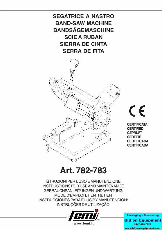
ISTRUZIONI PER L’USO E MANUTENZIONEINSTRUCTIONS FOR USE AND MAINTENANCEGEBRAUCHSANLEITUNGEN UND WARTUNG
MODE D’EMPLOI ET ENTRETIENINSTRUCCIONES PARA EL USO Y MANUTENCION/
INSTRUÇÕES DE UTILIZAÇÃO
SEGATRICE A NASTROBAND-SAW MACHINE
BANDSÄGEMASCHINESCIE A RUBAN
SIERRA DE CINTASERRA DE FITA
CERTIFICATACERTIFIEDGEPRÜFTCERTIFIECERTIFICADACERTIFICADA
Art. 782-783
www.femi.it
DICHIARAZIONE DI CONFORMITÁ CEDEL COSTRUTTORE FEMI S.p.A.
Via del Lavoro, 4 - 40023 Castel Guelfo (BO) - ITALIATel. +39-0542-670160 - Fax +39-0542-670185 - http://www.femi.it
Dichiara che la: SEGATRICE A NASTRO FEMI 782-783è conforme alle disposizioni contenute nelle Direttive:
CEE 98/37 - 89/336 - 73/23
COMPLIANCE DECLARATION CEOF THE BUILDER FEMI S.p.A.
Via del Lavoro, 4 - 40023 Castel Guelfo (BO) - ITALIATel. +39-0542-670160 - Fax +39-0542-670185 - http://www.femi.it
Declare the: BAND-SAW MACHINE FEMI 782-783is in compliance with the rules contents in the Directives:
CEE 98/37 - 89/336 - 73/23
CE KONFORMITATS ERKLARUNGDES HERSTELLER FEMI S.p.A.
Via del Lavoro, 4 - 40023 Castel Guelfo (BO) - ITALIATel. +39-0542-670160 - Fax +39-0542-670185 - http://www.femi.it
Erklart dass: BANDSÄGEMASCHINE FEMI 782-783ist konform mit der Direktiven:
CEE 98/37 - 89/336 - 73/23
DECLARATION DE CONFORMITE CEDU CONSTRUCTEUR FEMI S.p.A.
Via del Lavoro, 4 - 40023 Castel Guelfo (BO) - ITALIATel. +39-0542-670160 - Fax +39-0542-670185 - http://www.femi.it
Declare que la: SCIE A RUBAN FEMI 782-783est conforme aux disposition contenues dans les Directives: CEE
98/37 - 89/336 - 73/23
DECLARATION DE CONFORMIDAD CEDEL CONSTRUCTOR FEMI S.p.A.
Via del Lavoro, 4 - 40023 Castel Guelfo (BO) - ITALIATel. +39-0542-670160 - Fax +39-0542-670185 - http://www.femi.it
Declara que la: SIERRA DE CINTA FEMI 782-783esta conforme a las disposiciones contenide en la Directivas:
CEE 98/37 - 89/336 - 73/23
DECLARAÇÃO DE CONFORMIDADE CEDO CONSTRUTTORE FEMI S.p.A.
Via del Lavoro, 4 - 40023 Castel Guelfo (BO) - ITALIATel. +39-0542-670160 - Fax +39-0542-670185 - http://www.femi.it
Declara que a: SERRA DE FITA FEMI 782-783suivindo as regras exigidas no contendo da Directivas:
CEE 98/37 - 89/336 - 73/23
INDICE/ INDEX / INHALT / INDEX / INDICE / ÍNDICEITALIANO (IT) ............................................................................................................... 1 ÷ 6ENGLISH (EN) ............................................................................................................. 7 ÷ 12DEUTSCH (DE) ......................................................................................................... 13 ÷ 18FRANCAIS (FR) ........................................................................................................ 19 ÷ 24ESPANOL (ES) ......................................................................................................... 25 ÷ 30PORTUGUÊS (PT) ..................................................................................................... 31÷ 36
INGOMBRO PERETICHETTA
7
EN
1 INTRODUCTION TO USE
Before starting work with your sawing machine, carefullyread this instructions manual so that you are familiar withthe machine and its uses and where it should not be used.Keep this manual in a safe place.It is an integral part of the machine and should be used forreference in operating the machine correctly and in theproper safety conditions.Use the machine only and exclusively for the usesspecified below, as recommended in this manual. Themachine should not in any way be tampered with, or forced,or used for unsuitable purposes.
1.1 SYMBOLS PLACED IN CORRESPONDANCEWITH USAGE POINTS
Never underestimate the warnings “ATTENTION -CAUTION” given in this manual.In order to draw the user’s attention and to preserve safety,hazardous operation are preceded by symbols and notesthat point out the danger and explain how to behave toavoid any risk.These symbols and notes are divided in three categories,identified by the following words:
ATTENTION: dangerous-behaviours that couldcause serious injuries.
CAUTION: behaviours that could cause slightinjuries or damages to things.
NOTE: the notes preceded by this symbols aretechnical and are aimed at making operations easier.
INDEX
1 INTRODUCTION TO USE ...................................... 7
2 INSTALLATION ......................................................... 8
3 ADJUSTMENT .......................................................... 9
4 USE .......................................................................... 9
5 ACCESSORIES ...................................................... 11
6 MAINTENANCE ...................................................... 11
7 TROUBLESHOOTING ........................................... 12
1.2 SAFETY AND RULES
The machine was designed and built according to theCommunity Directives in force: EEC 98/37- EEC 73/ 23 -EEC 89/336.The enclosed CE Declaration of conformity, togheter withthe CE mark on product, essentially comprise and are anintegral part of the machine: both guarantee productconformity with the aforesaid safety Directives.
1.3 RECOMMENDED AND NOT RECOMMENDEDUSAGE
This belt sawing machine was designed and constructedaccording to the most advanced technologies and may beused for all cutting requirements for metals commonlyused in industry and artisanship.It can cut:- COMMON STEELS (FE 37...)- SPECIAL STEELS (C 40, 18NiCrMo5...)- ALUMINIUM AND ITS ALLOYS- BRASS- BRONZE- STEEL TUBING (FE 35, FE 52...)- PROFILED SECTIONS IN SHEET METAL AND
ALUMINIUM
It is not suitable for cutting:- WOOD AND SIMILAR MATERIALS- BONE AND SIMILAR MATERIALS
ATTENTION: The band saw has been developedand manufactured to cut in dry condition; theuse of any cooler by lubricating oil makes themachine unusable.
Consult the relative sections for cutting capacities, thespeeds to use and the type of tools for use according tothe material to be cut and its section. (See list of contents).
1.4 STANDARD SAFETY PROCEDURS
- Do not use the machine in very damp places or in thepresence of inflammable liquids or gases.
- Do not use it in the open air when general weather andenvironmental conditions are unfavourable (eg.explosive atmospheres, during a storm or rain).
- Wear suitable clothes, without wide sleeves or articlessuch as scarves, chains and bracelets which could getcaught in the moving parts.
- Always use personal protection devices: protectivegoggles as recommended by safety standards, glovesof the right size, headphones or earplugs, and hairnetsif necessary.
- Use the tools recommended in this manual if you wantto achieve the best performance from your sawingmachine.
- Any power cable extensions must be type approvedand comply with safety standards.
- Avoid using the machine if your psycho-physicalcondition are precarious or upset.
8
EN
1.5 SAFETY PROCEDURS FOR FURTHER RISK
- Always keep processing residues away from the cuttingarea.
- Always use the clamp. The parts to be cut must alwaysbe held firmly in the clamp.
- Always keep hands away from the working areas whilethe machine is moving: before loading or unloading thepart, release the run button on the hand grip.
- Do not force the machine unnecessarily : excessivecutting pressure could cause rapid wear to the bladeand negatively influence the performance of themachine in terms of finishes and cutting precision.
1.6 NOISE CONDITIONS
In normal conditions of use as described in this manual,this belt sawing machine determines an equivalent level ofacoustic pressure:Leq = 82 dB(A) when operating unloaded;Leq = 84,3 dB(A) during processing (eg. cutting of a
steel tube D.80 mm thickness 5 mm), at cuttingspeed of 80 m/min., with a weighted operatingcycle of 1 minute.
The frequency root mean RMS weighed for hand-armacceleration does not exceed 2.5m/s².Measurement were obteined in compliance with UNI7712, ISO 3740, ISO 3746 and CEE 89/392 regulation.
NOTE: Personal hearing protection should beused, such as headphones or earplugs.
1.7 INFORMATION ABOUT THEELECTROMAGNETIC COMPATIBILITY
The European regulations on safety and, in particular, theEEC Directive 89/336 contemplate that all the equipmentbe equipped with shielding devices against radiointerferences both from and towards the outside.This machine is equipped with filters both on the motor andon the power supply through which the machine is safe andin compliance with above regulations.Tests were carried out according to EN 55011, EN55014, EN 50082-1, IEC 1000-4-2, IEC 1000-4-4regulations.
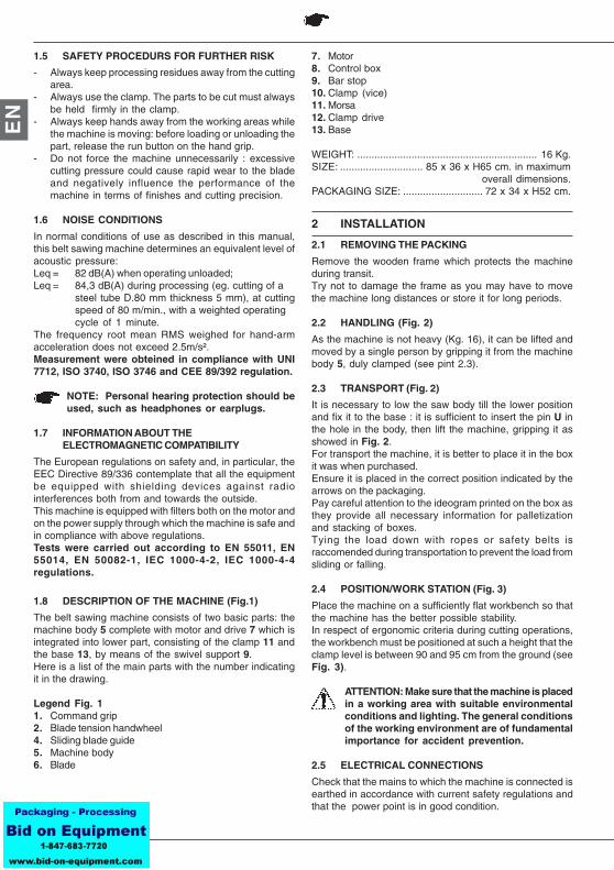
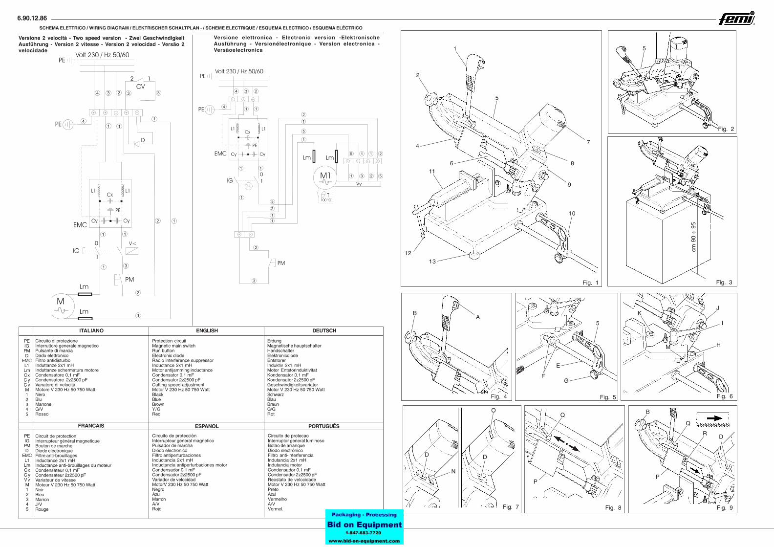
1.8 DESCRIPTION OF THE MACHINE (Fig.1)
The belt sawing machine consists of two basic parts: themachine body 5 complete with motor and drive 7 which isintegrated into lower part, consisting of the clamp 11 andthe base 13, by means of the swivel support 9.Here is a list of the main parts with the number indicatingit in the drawing.
Legend Fig. 11. Command grip2. Blade tension handwheel4. Sliding blade guide5. Machine body6. Blade
7. Motor8. Control box9. Bar stop10. Clamp (vice)11. Morsa12. Clamp drive13. Base
WEIGHT: ............................................................... 16 Kg.SIZE: ............................. 85 x 36 x H65 cm. in maximum
overall dimensions.PACKAGING SIZE: ............................ 72 x 34 x H52 cm.
2 INSTALLATION
2.1 REMOVING THE PACKING
Remove the wooden frame which protects the machineduring transit.Try not to damage the frame as you may have to movethe machine long distances or store it for long periods.
2.2 HANDLING (Fig. 2)
As the machine is not heavy (Kg. 16), it can be lifted andmoved by a single person by gripping it from the machinebody 5, duly clamped (see pint 2.3).
2.3 TRANSPORT (Fig. 2)
It is necessary to low the saw body till the lower positionand fix it to the base : it is sufficient to insert the pin U inthe hole in the body, then lift the machine, gripping it asshowed in Fig. 2.For transport the machine, it is better to place it in the boxit was when purchased.Ensure it is placed in the correct position indicated by thearrows on the packaging.Pay careful attention to the ideogram printed on the box asthey provide all necessary information for palletizationand stacking of boxes.Tying the load down with ropes or safety belts israccomended during transportation to prevent the load fromsliding or falling.
2.4 POSITION/WORK STATION (Fig. 3)
Place the machine on a sufficiently flat workbench so thatthe machine has the better possible stability.In respect of ergonomic criteria during cutting operations,the workbench must be positioned at such a height that theclamp level is between 90 and 95 cm from the ground (seeFig. 3).
ATTENTION: Make sure that the machine is placedin a working area with suitable environmentalconditions and lighting. The general conditionsof the working environment are of fundamentalimportance for accident prevention.
2.5 ELECTRICAL CONNECTIONS
Check that the mains to which the machine is connected isearthed in accordance with current safety regulations andthat the power point is in good condition.
9
EN
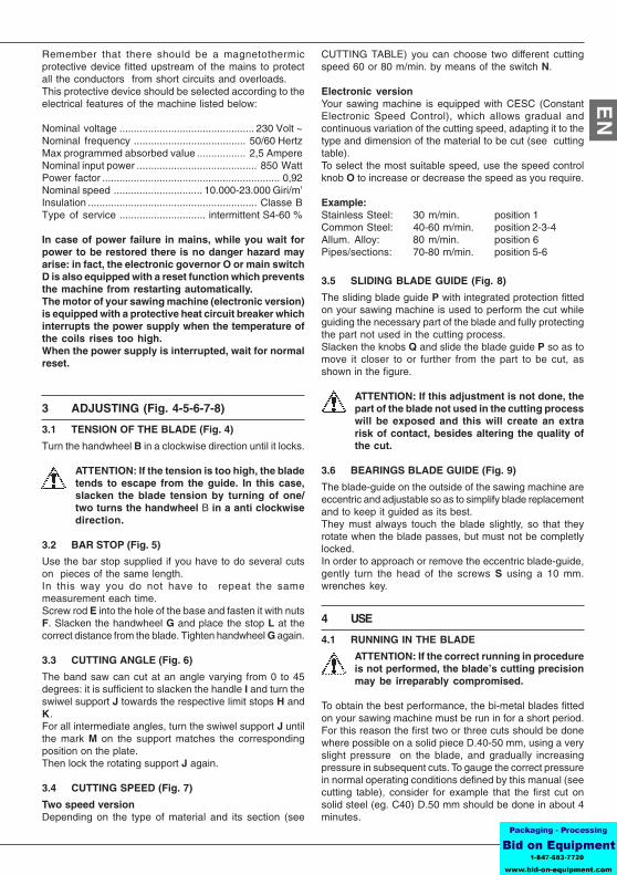
Remember that there should be a magnetothermicprotective device fitted upstream of the mains to protectall the conductors from short circuits and overloads.This protective device should be selected according to theelectrical features of the machine listed below:
Nominal voltage ............................................... 230 Volt ~Nominal frequency ....................................... 50/60 HertzMax programmed absorbed value ................. 2,5 AmpereNominal input power .......................................... 850 WattPower factor .............................................................. 0,92Nominal speed ............................... 10.000-23.000 Giri/m’Insulation ........................................................... Classe BType of service .............................. intermittent S4-60 %
In case of power failure in mains, while you wait forpower to be restored there is no danger hazard mayarise: in fact, the electronic governor O or main switchD is also equipped with a reset function which preventsthe machine from restarting automatically.The motor of your sawing machine (electronic version)is equipped with a protective heat circuit breaker whichinterrupts the power supply when the temperature ofthe coils rises too high.When the power supply is interrupted, wait for normalreset.
3 ADJUSTING (Fig. 4-5-6-7-8)
3.1 TENSION OF THE BLADE (Fig. 4)
Turn the handwheel B in a clockwise direction until it locks.
ATTENTION: If the tension is too high, the bladetends to escape from the guide. In this case,slacken the blade tension by turning of one/two turns the handwheel B in a anti clockwisedirection.
3.2 BAR STOP (Fig. 5)
Use the bar stop supplied if you have to do several cutson pieces of the same length.In this way you do not have to repeat the samemeasurement each time.Screw rod E into the hole of the base and fasten it with nutsF. Slacken the handwheel G and place the stop L at thecorrect distance from the blade. Tighten handwheel G again.
3.3 CUTTING ANGLE (Fig. 6)
The band saw can cut at an angle varying from 0 to 45degrees: it is sufficient to slacken the handle I and turn theswiwel support J towards the respective limit stops H andK.For all intermediate angles, turn the swiwel support J untilthe mark M on the support matches the correspondingposition on the plate.Then lock the rotating support J again.
3.4 CUTTING SPEED (Fig. 7)
Two speed versionDepending on the type of material and its section (see
CUTTING TABLE) you can choose two different cuttingspeed 60 or 80 m/min. by means of the switch N.
Electronic versionYour sawing machine is equipped with CESC (ConstantElectronic Speed Control), which allows gradual andcontinuous variation of the cutting speed, adapting it to thetype and dimension of the material to be cut (see cuttingtable).To select the most suitable speed, use the speed controlknob O to increase or decrease the speed as you require.
Example:Stainless Steel: 30 m/min. position 1Common Steel: 40-60 m/min. position 2-3-4Allum. Alloy: 80 m/min. position 6Pipes/sections: 70-80 m/min. position 5-6
3.5 SLIDING BLADE GUIDE (Fig. 8)
The sliding blade guide P with integrated protection fittedon your sawing machine is used to perform the cut whileguiding the necessary part of the blade and fully protectingthe part not used in the cutting process.Slacken the knobs Q and slide the blade guide P so as tomove it closer to or further from the part to be cut, asshown in the figure.
ATTENTION: If this adjustment is not done, thepart of the blade not used in the cutting processwill be exposed and this will create an extrarisk of contact, besides altering the quality ofthe cut.
3.6 BEARINGS BLADE GUIDE (Fig. 9)
The blade-guide on the outside of the sawing machine areeccentric and adjustable so as to simplify blade replacementand to keep it guided as its best.They must always touch the blade slightly, so that theyrotate when the blade passes, but must not be completlylocked.In order to approach or remove the eccentric blade-guide,gently turn the head of the screws S using a 10 mm.wrenches key.
4 USE
4.1 RUNNING IN THE BLADE
ATTENTION: If the correct running in procedureis not performed, the blade’s cutting precisionmay be irreparably compromised.
To obtain the best performance, the bi-metal blades fittedon your sawing machine must be run in for a short period.For this reason the first two or three cuts should be donewhere possible on a solid piece D.40-50 mm, using a veryslight pressure on the blade, and gradually increasingpressure in subsequent cuts. To gauge the correct pressurein normal operating conditions defined by this manual (seecutting table), consider for example that the first cut onsolid steel (eg. C40) D.50 mm should be done in about 4minutes.
10
EN
After running-in, the same piece may easily be cut inabout 2 minutes. If the running-in process is done correctly,the finish and precision of the cut will be of better qualityand the blade will last longer.
4.2 WORKING (Fig. 7)
Two speed versionPush the green button “1” of the main switch D to anablemachine operation.
Electronic versionTurn the main switch D to position 1: in doing the switchcomes on and machine is ready for operation.
ATTENTION: Before starting any cuttingoperation, check that all the protections arecomplete and in the correct position.
Once you have completed all the procedures and operationsdescribed so far, you may start the working processes.To perform the cut, move to the front of the machine andgrip the handgrip with your right hand.
ATTENTION: Keep your left hand away from thecutting area and on no account try to reach itwhen cutting is in process.
Using the index finger of your right hand, press the runbutton A (Fig. 4) and gradually lower the machine bodyuntil it comes lightly into contact with the part to be cut.Now begin to apply gradual pressure on the part andcomplete the cut.
ATTENTION: Always release button A betweenone cutting operation and another, while youare positioning the part. do not try to block itor alter its functional characteristics in anyway.
Electronic versionIf the machine suddenly stops after numerous consecutivecuts, do not be alarmed.The heat protector device of the motor has been activated,breaking the power supply when the temperature of thecoils reaches the threshold limit defined by the insulationclass, to prevent damage to the motor.In this case, release the button A and wait for automaticreset which usually takes place after a few minutes.Your sawing machine is equipped with an electronic speedgovernor which also includes a motor protection functionobtained by means of an amperometric limiter. In this waycan not absorb an amount of current greater than the setone, expressed by the maximum value of absorption (see2.5).If the limiter trips while the machine is in operation, slightlydecrease the cutting pressure in addition, this enables tosafeguard the blade life and performance and to obtainalways a sharp and clean cut.
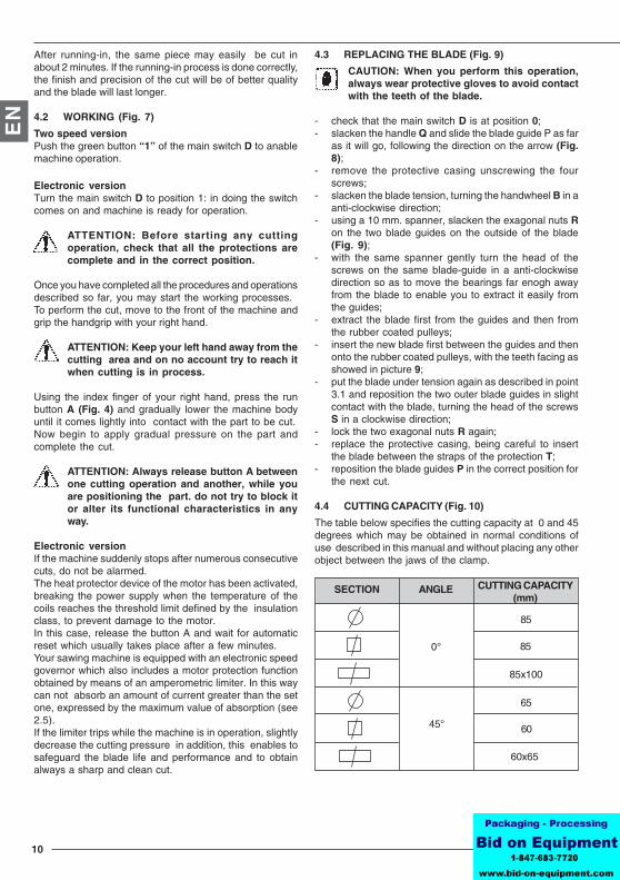
4.3 REPLACING THE BLADE (Fig. 9)
CAUTION: When you perform this operation,always wear protective gloves to avoid contactwith the teeth of the blade.
- check that the main switch D is at position 0;- slacken the handle Q and slide the blade guide P as far
as it will go, following the direction on the arrow (Fig.8);
- remove the protective casing unscrewing the fourscrews;
- slacken the blade tension, turning the handwheel B in aanti-clockwise direction;
- using a 10 mm. spanner, slacken the exagonal nuts Ron the two blade guides on the outside of the blade(Fig. 9);
- with the same spanner gently turn the head of thescrews on the same blade-guide in a anti-clockwisedirection so as to move the bearings far enogh awayfrom the blade to enable you to extract it easily fromthe guides;
- extract the blade first from the guides and then fromthe rubber coated pulleys;
- insert the new blade first between the guides and thenonto the rubber coated pulleys, with the teeth facing asshowed in picture 9;
- put the blade under tension again as described in point3.1 and reposition the two outer blade guides in slightcontact with the blade, turning the head of the screwsS in a clockwise direction;
- lock the two exagonal nuts R again;- replace the protective casing, being careful to insert
the blade between the straps of the protection T;- reposition the blade guides P in the correct position for
the next cut.
4.4 CUTTING CAPACITY (Fig. 10)
The table below specifies the cutting capacity at 0 and 45degrees which may be obtained in normal conditions ofuse described in this manual and without placing any otherobject between the jaws of the clamp.
0°
45°
85
85
85x100
65
60
60x65
SECTION ANGLE CUTTING CAPACITY(mm)
11
EN
Electronic version
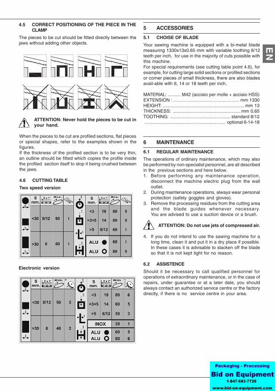
4.5 CORRECT POSITIONING OF THE PIECE IN THECLAMP
The pieces to be cut should be fitted directly between thejaws without adding other objects.
ATTENTION: Never hold the pieces to be cut inyour hand.
When the pieces to be cut are profiled sections, flat piecesor special shapes, refer to the examples shown in thefigures.If the thickness of the profiled section is to be very thin,an outline should be fitted which copies the profile insidethe profiled section itself to stop it being crushed betweenthe jaws.
4.6 CUTTING TABLE
Two speed version
5 ACCESSORIES
5.1 CHOISE OF BLADE
Your sawing machine is equipped with a bi-metal blademeasuring 1330x13x0.65 mm with variable toothing 8/12teeth per inch, for use in the majority of cuts possible withthis machine.For special requirements (see cutting table point 4.6), forexample, for cutting large solid sections or profiled sectionsor corner pieces of small thickness, there are also bladesavail-able with 6, 14 or 18 teeth per inch.
MATERIAL: .......... M42 (acciaio per molle + acciaio HSS)EXTENSION : .................................................... mm 1330HEIGHT: ................................................................ mm 13THICKNESS: ..................................................... mm 0,65TOOTHING: ............................................... standard 8/12............................................................... optional 6-14-18
6 MAINTENANCE
6.1 REGULAR MAINTENANCE
The operations of ordinary maintenance, which may alsobe performed by non-specialist personnel, are all describedin the previous sections and here below.1. Before performing any maintenance operation,
disconnect the machine electric plug from the walloutlet.
2. During maintenance operations, always wear personalprotection (safety goggles and gloves).
3. Remove the processing residues from the cutting areaand the blade guides whenever necessary.You are advised to use a suction device or a brush.
ATTENTION: Do not use jets of compressed air.
4. If you do not intend to use the sawing machine for along time, clean it and put it in a dry place if possible.In these cases it is advisable to slacken off the bladeso that it is not kept tight for no reason.
6.2 ASSISTENCE
Should it be necessary to call qualified personnel foroperations of extraordinary maintenance, or in the case ofrepairs, under guarantee or at a later date, you shouldalways contact an authorized service centre or the factorydirectly, if there is no service centre in your area.
12
EN
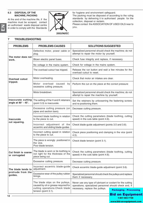
Defective motor, power cable orplug.
Blown electric panel fuses.
No voltage in the mains system.
The overload cutout has tripped.
Motor overheating.
Motor overload caused byexcessive cutting pressure.
Motor breakdown.
The setting of the H and K retainers(point 3.3) is inaccurate.
Excessive cutting pressure (onpipes and section bars).
Incorrect blade toothing in relationto the piece to cut.
Incorrect adjustment of theeccentric and sliding blade-guides
Incorrect cutting speed in relationto the piece to cut.
The piece is wrongly positioned inthe vice.Poor blade tension.
The blade is worn or its toothing isnot right for the thickness of thepiece being cut.
Excessive cutting pressure.
Incorrect eccentric blade-guideadjustment.
Excessive wear of the pulley rubberlinings.
The blade slips on the pulleys,caused by oil or grease required forcutting operations.Check bladetension (point 3.1).
The motor does notwork.
Overload cutouttripped.
Inaccurate cuttingangle at 90° - 45°.
Inaccuratecut squaring.
Cut finish is coarseor corrugated
The blade tends toprotrude from theguides.
Specialized personnel should check the machine; do notattempt to repair the motor by yourself.
Check fuse integrity and replace, if necessary.
Check for voltage in the mains system.
Release the run button and wait a few minutes for theoverload cutout to reset.
Check that motor air intakes are clear.
Perform the cut on the piece at the correct pressure
Specialized personnel should check the machine; do notattempt to repair the machine by yourself.
Set the retainers by unloosening the fastening screwsand re-positioning them.
Decrease cutting pressure.
Check the cutting parameters (blade toothing, cuttingspeed) in the cuts table (point 4.6).
Check blade-guide adjustment (points 3.5 and 3.6).
Check piece positioning and clamping in the vice (point4.5).
Check blade tension (point 3.1).
Check the cutting parameters (blade toothing, cuttingspeed) in the cuts table (point 4.6).
Decrease cutting pressure.
Check eccentric blade-guide adjustment (point 3.6).
Specialized personnel should check the pulleys and replacethem if necessary.
Never use any type of lubricant or coolant for the cuttingoperations; specialized personnel should check and, ifnecessary, replace the pulleys.
PROBLEMS PROBLEMS CAUSES SOLUTIONS SUGGESTED
6.3 DISPOSAL OF THEMACHINE, PACKING
At the end of the machine life, if themachine must be scraped, contactan authorised waste disposal centrein order to comply with the Standards
for hygiene and environment safeguard.The packing must be disposed of according to the rulingstandards by delivering it to authorised people for thecollection, disposal or reclaim.Please contact the ASSOCIATION OF USED OILS near toyou.
7 TROUBLESHOOTING
2002/96/EC
6.90.12.86
Versione 2 velocità - Two speed version - Zwei GeschwindigkeitAusführung - Version 2 vitesse - Version 2 velocidad - Versão 2velocidade
Fig. 1 Fig. 3
Fig. 4 Fig. 5 Fig. 6
Fig. 7 Fig. 8 Fig. 9
Fig. 2
cm 9
0 ÷
95
1
2
4
611
10
9
7
8
5U
13
F
J
H
I
M
K
P
Q
12
5
R
P
Q
B
D
D
N
D
O
AB
5
G
E
3
2
2
2
2
2
2
1 1
1
1
1 1
1
11
11
1
3
3
4
4
5
5
5
5
SCHEMA ELETTRICO / WIRING DIAGRAM / ELEKTRISCHER SCHALTPLAN - / SCHEME ELECTRIQUE / ESQUEMA ELECTRICO / ESQUEMA ELÉCTRICO
PEIGPMD
EMCL1LmCxC yC vM12345
Circuito di protezioneInterruttore generale magneticoPulsante di marciaDado elettronicoFiltro antidisturboInduttanze 2x1 mHInduttanze schermatura motoreCondensatore 0,1 mFCondensatore 2z2500 pFVanatore di velocitàMotore V 230 Hz 50 750 WattNeroBluMarroneG/VRosso
Protection circuitMagnetic main switchRun buttonElectronic diodeRadio interference suppressorInductance 2x1 mHMotor antijamming inductanceCondensator 0,1 mFCondensator 2z2500 pFCutting speed adjustmentMotor V 230 Hz 50 750 WattBlackBlueBrownY/GRed
ErdungMagnetische hauptschalterHandschalterElektronicdiodeEntstorerInduktiv 2x1 mHMotor EntstorinduktivitatKondensator 0,1 mFKondensator 2z2500 pFGeschwindigkeitsvariatorMotor V 230 Hz 50 750 WattSchwarzBlauBraunG/GRot
ITALIANO ENGLISH DEUTSCH
FRANCAIS
Circuit de protectionInterrupteur général magnetiqueBouton de marcheDiode eléctroniqueFiltre anti-brouillagesInductance 2x1 mHInductance anti-brouillages du moteurCondensateur 0,1 mFCondensateur 2z2500 pFVariateur de vitesseMoteur V 230 Hz 50 750 WattNoirBleuMarronJ/VRouge
PEIGPMD
EMCL1LmCxC yVvM12345
ESPANOL PORTUGUÊS
Circuito de protecciònInterrupteur general magneticoPulsador de marchaDiodo electronicoFiltro antiperturbacionesInductancia 2x1 mHInductancia antiperturbaciones motorCondensador 0,1 mFCondensador 2z2500 pFVariador de velocidadMotorV 230 Hz 50 750 WattNegroAzulMarronA/VRojo
Circuito de protecaoInterruptor general luminosoBotao de arranqueDiodo electrónicoFiltro anti-interferenciaIndutancia 2x1 mHIndutancia motorCondensador 0,1 mFCondensador 2z2500 pFReostato de velocidadeMotor V 230 Hz 50 750 WattPretoAzulVermelhoA/VVermel.
Versione elettronica - Electronic version -ElektronischeAusführung - Versionélectronique - Version electronica -Versãoelectronica
4
4
3 33
3
1
11
1
1 1
1
1
2
2
2
6.90.12.86
80
3611781
83
8281
8990
8887
969592
9998
101100
108109
97
94939291
868584
11411511627
118119138
105104103102
106
107
134135
127
110111
124125
126
136123
137
122121
123
120
129132131
128130133
128
139
50112113
2928
46
453231
48
45
109
12
11
14
16
1918
20
2122
2324
25
26
47
2852
3938
46
30
28
4443
7877
76
3
41
21
1715
5
76
8
515049
7374
7170
72
6867
6566 56
55
5441
4253
44
43
69
6360
62
64
383940
79
75
616059
5857
34
37
33
3635
323130
2928
27
13
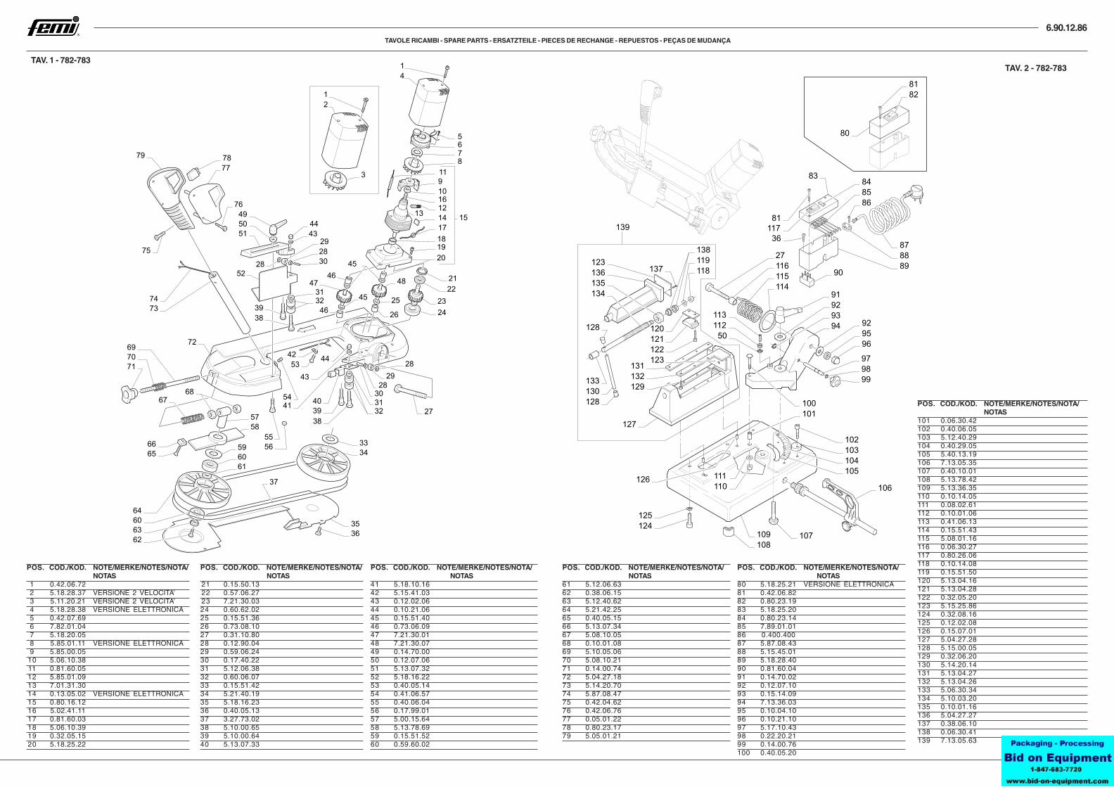
TAV. 1 - 782-783
TAVOLE RICAMBI - SPARE PARTS - ERSATZTEILE - PIECES DE RECHANGE - REPUESTOS - PEÇAS DE MUDANÇA
TAV. 2 - 782-783
POS. COD./KOD. NOTE/MERKE/NOTES/NOTA/NOTAS
1 0.42.06.722 5.18.28.37 VERSIONE 2 VELOCITA’3 5.11.20.21 VERSIONE 2 VELOCITA’4 5.18.28.38 VERSIONE ELETTRONICA5 0.42.07.696 7.82.01.047 5.18.20.058 5.85.01.11 VERSIONE ELETTRONICA9 5.85.00.05
10 5.06.10.3811 0.81.60.0512 5.85.01.0913 7.01.31.3014 0.13.05.02 VERSIONE ELETTRONICA15 0.80.16.1216 5.02.41.1117 0.81.60.0318 5.06.10.3919 0.32.05.1520 5.18.25.22
POS. COD./KOD. NOTE/MERKE/NOTES/NOTA/NOTAS
21 0.15.50.1322 0.57.06.2723 7.21.30.0324 0.60.62.0225 0.15.51.3626 0.73.08.1027 0.31.10.8028 0.12.90.0429 0.59.06.2430 0.17.40.2231 5.12.06.3832 0.60.06.0733 0.15.51.4234 5.21.40.1935 5.18.16.2336 0.40.05.1337 3.27.73.0238 5.10.00.6539 5.10.00.6440 5.13.07.33
POS. COD./KOD. NOTE/MERKE/NOTES/NOTA/NOTAS
41 5.18.10.1642 5.15.41.0343 0.12.02.0644 0.10.21.0645 0.15.51.4046 0.73.06.0947 7.21.30.0148 7.21.30.0749 0.14.70.0050 0.12.07.0651 5.13.07.3252 5.18.16.2253 0.40.05.1454 0.41.06.5755 0.40.06.0456 0.17.99.0157 5.00.15.6458 5.13.78.6959 0.15.51.5260 0.59.60.02
POS. COD./KOD. NOTE/MERKE/NOTES/NOTA/NOTAS
61 5.12.06.6362 0.38.06.1563 5.12.40.6264 5.21.42.2565 0.40.05.1566 5.13.07.3467 5.08.10.0568 0.10.01.0869 5.10.05.0670 5.08.10.2171 0.14.00.7472 5.04.27.1873 5.14.20.7074 5.87.08.4775 0.42.04.6276 0.42.06.7677 0.05.01.2278 0.80.23.1779 5.05.01.21
POS. COD./KOD. NOTE/MERKE/NOTES/NOTA/NOTAS
80 5.18.25.21 VERSIONE ELETTRONICA81 0.42.06.8282 0.80.23.1983 5.18.25.2084 0.80.23.1485 7.89.01.0186 0.400.40087 5.87.08.4388 5.15.45.0189 5.18.28.4090 0.81.60.0491 0.14.70.0292 0.12.07.1093 0.15.14.0994 7.13.36.0395 0.10.04.1096 0.10.21.1097 5.17.10.4398 0.22.20.2199 0.14.00.76100 0.40.05.20
POS. COD./KOD. NOTE/MERKE/NOTES/NOTA/NOTAS
101 0.06.30.42102 0.40.06.05103 5.12.40.29104 0.40.29.05105 5.40.13.19106 7.13.05.35107 0.40.10.01108 5.13.78.42109 5.13.36.35110 0.10.14.05111 0.08.02.61112 0.10.01.06113 0.41.06.13114 0.15.51.43115 5.08.01.16116 0.06.30.27117 0.80.26.06118 0.10.14.08119 0.15.51.50120 5.13.04.16121 5.13.04.28122 0.32.05.20123 5.15.25.86124 0.32.08.16125 0.12.02.08126 0.15.07.01127 5.04.27.28128 5.15.00.05129 0.32.06.20130 5.14.20.14131 5.13.04.27132 5.13.04.26133 5.06.30.34134 5.10.03.20135 0.10.01.16136 5.04.27.27137 0.38.06.10138 0.06.30.41139 7.13.05.63