Embed Size (px)
Citation preview
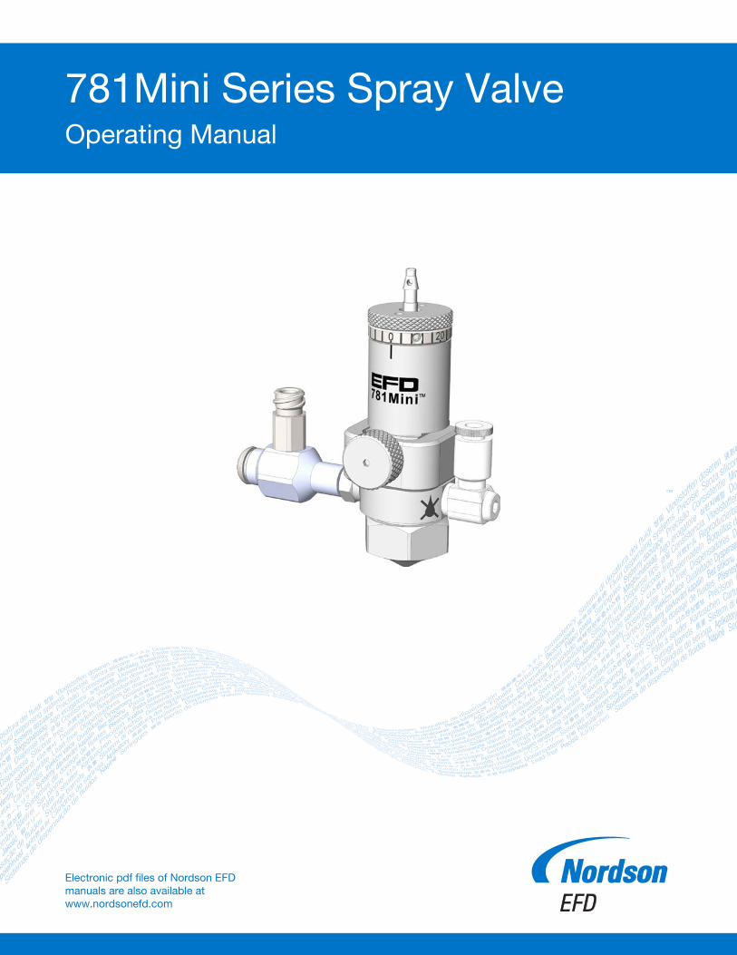
781Mini Series Spray ValveOperating Manual
™
Electronic pdf files of Nordson EFD manuals are also available at www.nordsonefd.com
781Mini Series Spray Valve
2 www.nordsonefd.com [email protected] +1-401-431-7000 Sales and service of Nordson EFD dispensing systems are available worldwide.
You have selected a reliable, high-quality dispensing system from Nordson EFD, the world leader in fluid dispensing. The 781Mini™ spray valve was designed specifically for industrial dispensing and will provide you with years of trouble-free, productive service.
This manual will help you maximize the usefulness of your 781Mini valve.
Please spend a few minutes to become familiar with the controls and features. Follow our recommended testing procedures. Review the helpful information we have included, which is based on more than 50 years of industrial dispensing experience.
Most questions you will have are answered in this manual. However, if you need assistance, please do not hesitate to contact EFD or your authorized EFD distributor. Detailed contact information is provided on the last page of this document.
The Nordson EFD Pledge
Thank You!
You have just purchased the world’s finest precision dispensing equipment.
I want you to know that all of us at Nordson EFD value your business and will do everything in our power to make you a satisfied customer.
If at any time you are not fully satisfied with our equipment or the support provided by your Nordson EFD Product Application Specialist, please contact me personally at 800.556.3484 (US), 401.431.7000 (outside US), or [email protected].
I guarantee that we will resolve any problems to your satisfaction.
Thanks again for choosing Nordson EFD.
Tara Tereso, Vice PresidentTara
781Mini Series Spray Valve
3www.nordsonefd.com [email protected] +1-401-431-7000 Sales and service of Nordson EFD dispensing systems are available worldwide.
Contents ..........................................................................................................................................................................3Introduction .....................................................................................................................................................................4
How the 781Mini Valve Operates ................................................................................................................................4How the QR Clasp Works ............................................................................................................................................5How to Control the 781Mini Valve ...............................................................................................................................5
Specifications ..................................................................................................................................................................6Operating Features ..........................................................................................................................................................6Installation .......................................................................................................................................................................7
Mounting the Valve on the Dispensing Equipment ......................................................................................................7Installing a 90° Fluid Inlet Fitting ..................................................................................................................................7Making the System Connections .................................................................................................................................8
ValveMate 8040 System with a 781Mini Valve.........................................................................................................8ValveMate 7140 System with a 781Mini Valve.........................................................................................................9
Round Pattern Spray Area Coverage ............................................................................................................................10Valve Stroke Calibration ................................................................................................................................................10Service ...........................................................................................................................................................................11
Cleaning the Wetted Parts .........................................................................................................................................11Replacing a Valve Component (Full Disassembly and Reassembly) .........................................................................14
Replacement Parts ........................................................................................................................................................16Troubleshooting ............................................................................................................................................................17
Contents

781Mini Series Spray Valve
4 www.nordsonefd.com [email protected] +1-401-431-7000 Sales and service of Nordson EFD dispensing systems are available worldwide.
IntroductionThe 781Mini precision Low Volume Low Pressure (LVLP) liquid spray valve is designed for high transfer efficiency without overspray or airborne mist and provides consistent coating application of low-to-medium viscosity fluids. 781Mini spray valves are simple to use and will operate many millions of cycles without maintenance.
The fluid body offers 360° rotational movement, allowing the fluid inlet to be positioned in the best orientation for fluid feed to the valve.
The valve’s unique quick-release (QR) clasp secures the fluid body to the air cylinder body and can be removed in seconds for fast change-out and easy cleaning and maintenance of the valve’s wetted parts.
How the 781Mini Valve OperatesInput air pressure at 4.8 bar (70 psi) retracts the piston and needle from the needle seat in the nozzle, permitting fluid flow through the nozzle. At the same time, nozzle air flows around the liquid exiting the nozzle. This adjustable nozzle air creates a pressure drop around the nozzle, causing the liquid to atomize into fine droplets.
The amount sprayed is controlled by the valve open time, reservoir pressure, and needle stroke. The area of coverage is determined by the nozzle size and the distance between the nozzle and the work surface.
Once the cycle is complete, air pressure is exhausted, causing the piston spring to return the needle back to its position in the nozzle, stopping fluid flow.
Fluid body rotates for 360°
movement
QR clasp can be removed for fast
valve change-out
Closed Open
781Mini Series Spray Valve
5www.nordsonefd.com [email protected] +1-401-431-7000 Sales and service of Nordson EFD dispensing systems are available worldwide.
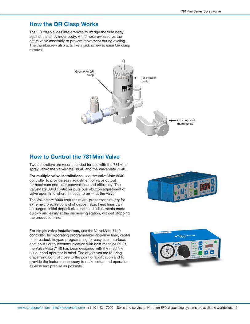
How the QR Clasp WorksThe QR clasp slides into grooves to wedge the fluid body against the air cylinder body. A thumbscrew secures the entire valve assembly to prevent movement during cycling. The thumbscrew also acts like a jack screw to ease QR clasp removal.
Groove for QR clasp
QR clasp and thumbscrew
Air cylinder body
How to Control the 781Mini ValveTwo controllers are recommended for use with the 781Mini spray valve: the ValveMate™ 8040 and the ValveMate 7140.
For multiple valve installations, use the ValveMate 8040 controller to provide easy adjustment of valve output for maximum end-user convenience and efficiency. The ValveMate 8040 controller puts push-button adjustment of valve open time where it needs to be — at the valve.
The ValveMate 8040 features micro-processor circuitry for extremely precise control of deposit size. Feed lines can be purged, initial deposit sizes set, and adjustments made quickly and easily at the dispensing station, without stopping the production line.
For single valve installations, use the ValveMate 7140 controller. Incorporating programmable dispense time, digital time readout, keypad programming for easy user interface, and input / output communication with host machine PLCs, the ValveMate 7140 has been designed with the machine builder and operator in mind. The objectives are to bring dispensing control close to the point of application and to provide the features necessary to make setup and operation as easy and precise as possible.
781Mini Series Spray Valve
6 www.nordsonefd.com [email protected] +1-401-431-7000 Sales and service of Nordson EFD dispensing systems are available worldwide.
SpecificationsNOTE: Specifications and technical details are subject to change without prior notification.
Item Specification
Size 71.4L x 22.4DIA mm (2.88L x 0.88DIA")
Weight 141.0 g (5.0 oz)
Actuating air pressure required
4.8–6.2 bar (70–90 psi)
Maximum fluid pressure 7.0 bar (100 psi)
Fluid inlet M5
Mounting M4
Cycle rate Exceeds 400 per minute
Actuating air inlet 4 mm OD tubing, barb fitting
Air cylinder body 303 stainless steel
Fluid body 303 stainless steel
Air cap 303 stainless steel
Piston 303 stainless steel
Needle and nozzle 303 stainless steel
Maximum operating temperature
102º C (215º F)
All stainless steel valve parts are passivated.US Patent No. 9,816,849 for QR clasp.
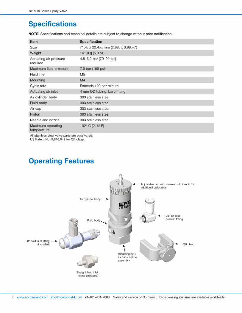
Operating Features
Adjustable cap with stroke control knob for additional calibration
90° air inlet push-in fitting
Air cylinder body
90° fluid inlet fitting (included)
Straight fluid inlet fitting (included)
QR clasp
Fluid body
Retaining nut / air cap / nozzle assembly
781Mini Series Spray Valve
7www.nordsonefd.com [email protected] +1-401-431-7000 Sales and service of Nordson EFD dispensing systems are available worldwide.
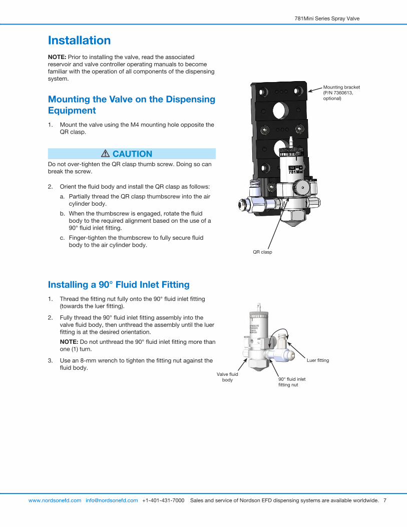
InstallationNOTE: Prior to installing the valve, read the associated reservoir and valve controller operating manuals to become familiar with the operation of all components of the dispensing system.
Mounting the Valve on the Dispensing Equipment1. Mount the valve using the M4 mounting hole opposite the
QR clasp.
CAUTIONDo not over-tighten the QR clasp thumb screw. Doing so can break the screw.
2. Orient the fluid body and install the QR clasp as follows:
a. Partially thread the QR clasp thumbscrew into the air cylinder body.
b. When the thumbscrew is engaged, rotate the fluid body to the required alignment based on the use of a 90° fluid inlet fitting.
c. Finger-tighten the thumbscrew to fully secure fluid body to the air cylinder body.
Installing a 90° Fluid Inlet Fitting1. Thread the fitting nut fully onto the 90° fluid inlet fitting
(towards the luer fitting).
2. Fully thread the 90° fluid inlet fitting assembly into the valve fluid body, then unthread the assembly until the luer fitting is at the desired orientation.
NOTE: Do not unthread the 90° fluid inlet fitting more than one (1) turn.
3. Use an 8-mm wrench to tighten the fitting nut against the fluid body.
QR clasp
Mounting bracket (P/N 7360613, optional)
Valve fluid body 90° fluid inlet
fitting nut
Luer fitting
781Mini Series Spray Valve
8 www.nordsonefd.com [email protected] +1-401-431-7000 Sales and service of Nordson EFD dispensing systems are available worldwide.
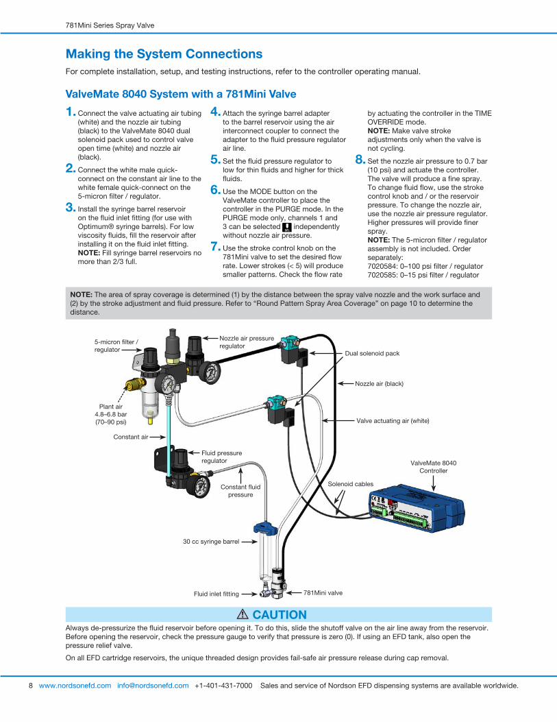
Making the System ConnectionsFor complete installation, setup, and testing instructions, refer to the controller operating manual.
ValveMate 8040 System with a 781Mini Valve
NOTE: The area of spray coverage is determined (1) by the distance between the spray valve nozzle and the work surface and (2) by the stroke adjustment and fluid pressure. Refer to “Round Pattern Spray Area Coverage” on page 10 to determine the distance.
Always de-pressurize the fluid reservoir before opening it. To do this, slide the shutoff valve on the air line away from the reservoir. Before opening the reservoir, check the pressure gauge to verify that pressure is zero (0). If using an EFD tank, also open the pressure relief valve.
On all EFD cartridge reservoirs, the unique threaded design provides fail-safe air pressure release during cap removal.
CAUTION
1. Connect the valve actuating air tubing (white) and the nozzle air tubing (black) to the ValveMate 8040 dual solenoid pack used to control valve open time (white) and nozzle air (black).
2. Connect the white male quick-connect on the constant air line to the white female quick-connect on the 5-micron filter / regulator.
3. Install the syringe barrel reservoir on the fluid inlet fitting (for use with Optimum® syringe barrels). For low viscosity fluids, fill the reservoir after installing it on the fluid inlet fitting. NOTE: Fill syringe barrel reservoirs no more than 2/3 full.
4. Attach the syringe barrel adapter to the barrel reservoir using the air interconnect coupler to connect the adapter to the fluid pressure regulator air line.
5. Set the fluid pressure regulator to low for thin fluids and higher for thick fluids.
6. Use the MODE button on the ValveMate controller to place the controller in the PURGE mode. In the PURGE mode only, channels 1 and 3 can be selected independently without nozzle air pressure.
7. Use the stroke control knob on the 781Mini valve to set the desired flow rate. Lower strokes (< 5) will produce smaller patterns. Check the flow rate
by actuating the controller in the TIME OVERRIDE mode. NOTE: Make valve stroke adjustments only when the valve is not cycling.
8. Set the nozzle air pressure to 0.7 bar (10 psi) and actuate the controller. The valve will produce a fine spray. To change fluid flow, use the stroke control knob and / or the reservoir pressure. To change the nozzle air, use the nozzle air pressure regulator. Higher pressures will provide finer spray. NOTE: The 5-micron filter / regulator assembly is not included. Order separately: 7020584: 0–100 psi filter / regulator 7020585: 0–15 psi filter / regulator
Nozzle air pressure regulator
5-micron filter /regulator
781Mini valve
30 cc syringe barrel
Constant air
Fluid pressure regulator
Constant fluid pressure
Valve actuating air (white)
ValveMate 8040 Controller
Plant air4.8–6.8 bar (70–90 psi)
Dual solenoid pack
Nozzle air (black)
Solenoid cables
Fluid inlet fitting
781Mini Series Spray Valve
9www.nordsonefd.com [email protected] +1-401-431-7000 Sales and service of Nordson EFD dispensing systems are available worldwide.
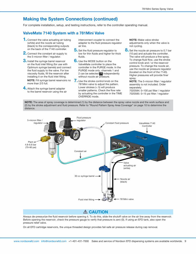
Making the System Connections (continued)For complete installation, setup, and testing instructions, refer to the controller operating manual.
ValveMate 7140 System with a 781Mini Valve
Always de-pressurize the fluid reservoir before opening it. To do this, slide the shutoff valve on the air line away from the reservoir. Before opening the reservoir, check the pressure gauge to verify that pressure is zero (0). If using an EFD tank, also open the pressure relief valve.
On all EFD cartridge reservoirs, the unique threaded design provides fail-safe air pressure release during cap removal.
CAUTION
1. Connect the valve actuating air tubing (white) and the nozzle air tubing (black) to the corresponding outputs on the back of the 7140 controller.
2. Connect the constant air supply to the 5-micron filter / regulator.
3. Install the syringe barrel reservoir on the fluid inlet fitting (for use with Optimum syringe barrels) and connect the fluid supply to the valve. For low viscosity fluids, fill the reservoir after installing it on the fluid inlet fitting. NOTE: Fill syringe barrel reservoirs no more than 2/3 full.
4. Attach the syringe barrel adapter to the barrel reservoir using the air
interconnect coupler to connect the adapter to the fluid pressure regulator air line.
5. Set the fluid pressure regulator to low for thin fluids and higher for thick fluids.
6. Use the MODE button on the ValveMate controller to place the controller in the PURGE mode. In the PURGE mode only, channels 1 and 2 can be selected independently without nozzle air pressure.
7. Use the stroke control knob on the 781Mini valve to adjust the pattern. Lower strokes (< 5) will produce smaller patterns. Check the flow rate by actuating the controller in the TIME OVERRIDE mode.
NOTE: Make valve stroke adjustments only when the valve is not cycling.
8. Set the nozzle air pressure to 0.7 bar (10 psi) and actuate the controller. The valve will produce a fine spray. To change fluid flow, use the stroke control knob and / or the reservoir pressure. To change the nozzle air, use the nozzle air pressure regulator (located on the front of the 7140). Higher pressures will provide finer spray. NOTE: The 5-micron filter / regulator assembly is not included. Order separately: 7020584: 0–100 psi filter / regulator 7020585: 0–15 psi filter / regulator
NOTE: The area of spray coverage is determined (1) by the distance between the spray valve nozzle and the work surface and (2) by the stroke adjustment and fluid pressure. Refer to “Round Pattern Spray Area Coverage” on page 10 to determine the distance.
5-micron filter /regulator
781Mini valveFluid inlet fitting
Plant air4.8–6.8 bar (70–90 psi)
ValveMate 7140 Controller
Constant fluid pressure
Fluid pressure regulator
Constant air
Valve actuating air (white)
Nozzle air (black)
30 cc syringe barrel
781Mini Series Spray Valve
10 www.nordsonefd.com [email protected] +1-401-431-7000 Sales and service of Nordson EFD dispensing systems are available worldwide.
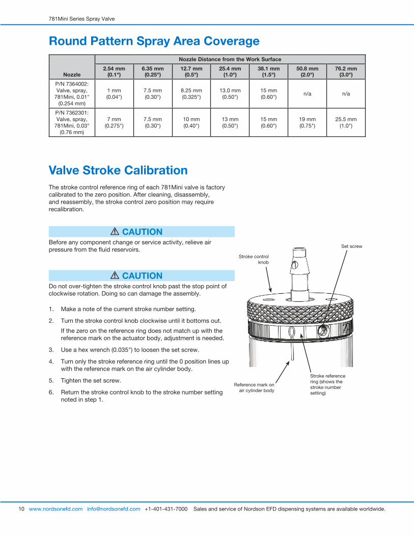
Valve Stroke CalibrationThe stroke control reference ring of each 781Mini valve is factory calibrated to the zero position. After cleaning, disassembly, and reassembly, the stroke control zero position may require recalibration.
CAUTIONBefore any component change or service activity, relieve air pressure from the fluid reservoirs.
CAUTIONDo not over-tighten the stroke control knob past the stop point of clockwise rotation. Doing so can damage the assembly.
1. Make a note of the current stroke number setting.
2. Turn the stroke control knob clockwise until it bottoms out.
If the zero on the reference ring does not match up with the reference mark on the actuator body, adjustment is needed.
3. Use a hex wrench (0.035") to loosen the set screw.
4. Turn only the stroke reference ring until the 0 position lines up with the reference mark on the air cylinder body.
5. Tighten the set screw.
6. Return the stroke control knob to the stroke number setting noted in step 1.
Round Pattern Spray Area Coverage
Nozzle
Nozzle Distance from the Work Surface
2.54 mm (0.1")
6.35 mm (0.25")
12.7 mm (0.5")
25.4 mm (1.0")
38.1 mm (1.5")
50.8 mm (2.0")
76.2 mm (3.0")
P/N 7364002: Valve, spray,
781Mini, 0.01" (0.254 mm)
1 mm (0.04")
7.5 mm (0.30")
8.25 mm (0.325")
13.0 mm (0.50")
15 mm (0.60")
n/a n/a
P/N 7362301: Valve, spray,
781Mini, 0.03" (0.76 mm)
7 mm (0.275")
7.5 mm (0.30")
10 mm (0.40")
13 mm (0.50")
15 mm (0.60")
19 mm (0.75")
25.5 mm (1.0")
Stroke control knob
Stroke reference ring (shows the stroke number setting)
Set screw
Reference mark on air cylinder body
781Mini Series Spray Valve
11www.nordsonefd.com [email protected] +1-401-431-7000 Sales and service of Nordson EFD dispensing systems are available worldwide.
ServicePerform these service procedures as needed for the best valve operation. You will need the following tools:
• 0.035" hex wrench (included)• 1.5 and 2.5 mm hex wrenches (included)• 3 mm hex wrench (included)• Snap-ring pliers (not included)• Adjustable wrench (not included)
CAUTIONBefore any component change or service activity, relieve air pressure from the fluid reservoirs.
Nozzle (PEEK nozzle shown)
Air cap
Air cap retaining nut
Fluid inlet fitting
QR clasp
Double-stacked O-rings
Nozzle air fitting
Fluid body
Removing the fluid body
Removing the nozzle
Stroke control knob
Nozzle O-ring
Nozzle dispersion ring
Cleaning the Wetted Parts
Disassemble the Wetted Parts
1. Disconnect the actuating air, nozzle air, and fluid supply from the valve.
2. Make a note of the current stroke setting number.
3. Loosen the stroke control knob until the spring pressure is relieved.
4. Turn the QR clasp thumbscrew counterclockwise to disengage the clasp.
5. Carefully move the fluid body downward until it clears the needle-and-piston assembly.
6. Remove the double-stacked O-rings from inside the fluid body (these O-rings typically remain in the fluid body after it is removed).
7. Remove the fluid inlet fitting and the nozzle air fitting.
8. Remove the air cap retaining nut and then remove the air cap and the nozzle components.
Clean the Wetted Parts
1. Clean the fluid body, nozzle, dispersion ring, air cap, and air cap retaining nut in an appropriate solvent.
CAUTIONDo not clean the needle with an abrasive material, specifically in chemically sensitive applications.
2. Clean the needle with a cloth dampened in solvent.
781Mini Series Spray Valve
12 www.nordsonefd.com [email protected] +1-401-431-7000 Sales and service of Nordson EFD dispensing systems are available worldwide.
Cleaning the Wetted Parts (continued)
Reassemble the Wetted Parts
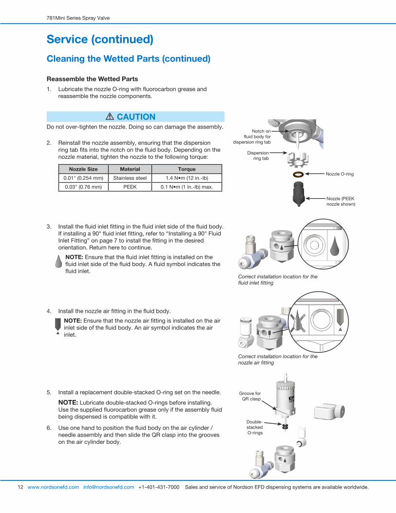
1. Lubricate the nozzle O-ring with fluorocarbon grease and reassemble the nozzle components.
CAUTIONDo not over-tighten the nozzle. Doing so can damage the assembly.
2. Reinstall the nozzle assembly, ensuring that the dispersion ring tab fits into the notch on the fluid body. Depending on the nozzle material, tighten the nozzle to the following torque:
Nozzle Size Material Torque
0.01" (0.254 mm) Stainless steel 1.4 N•m (12 in.-lb)
0.03" (0.76 mm) PEEK 0.1 N•m (1 in.-lb) max.
Service (continued)
Correct installation location for the fluid inlet fitting
Correct installation location for the nozzle air fitting
3. Install the fluid inlet fitting in the fluid inlet side of the fluid body. If installing a 90° fluid inlet fitting, refer to “Installing a 90° Fluid Inlet Fitting” on page 7 to install the fitting in the desired orientation. Return here to continue.
NOTE: Ensure that the fluid inlet fitting is installed on the fluid inlet side of the fluid body. A fluid symbol indicates the fluid inlet.
4. Install the nozzle air fitting in the fluid body.
NOTE: Ensure that the nozzle air fitting is installed on the air inlet side of the fluid body. An air symbol indicates the air inlet.
5. Install a replacement double-stacked O-ring set on the needle.
NOTE: Lubricate double-stacked O-rings before installing. Use the supplied fluorocarbon grease only if the assembly fluid being dispensed is compatible with it.
6. Use one hand to position the fluid body on the air cylinder / needle assembly and then slide the QR clasp into the grooves on the air cylinder body.
Nozzle (PEEK nozzle shown)
Nozzle O-ring
Dispersion ring tab
Notch on fluid body for
dispersion ring tab
Groove for QR clasp
Double-stacked O-rings
781Mini Series Spray Valve
13www.nordsonefd.com [email protected] +1-401-431-7000 Sales and service of Nordson EFD dispensing systems are available worldwide.
CAUTIONDo not over-tighten the QR clasp thumb screw. Doing so can break the screw.
7. Fully install the QR clasp as follows:
a. Partially thread the QR clasp thumbscrew into the air cylinder body.
b. When the thumbscrew is engaged, rotate the fluid body to the required alignment.
c. Finger-tighten the thumbscrew to fully secure fluid body to the air cylinder.
8. Reconnect the actuating air, nozzle air, and fluid supply to the valve.
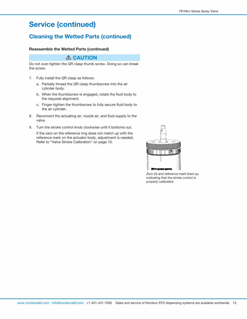
9. Turn the stroke control knob clockwise until it bottoms out.
If the zero on the reference ring does not match up with the reference mark on the actuator body, adjustment is needed. Refer to “Valve Stroke Calibration” on page 10.
Zero (0) and reference mark lined up, indicating that the stroke control is properly calibrated.
Service (continued)
Cleaning the Wetted Parts (continued)
Reassemble the Wetted Parts (continued)
781Mini Series Spray Valve
14 www.nordsonefd.com [email protected] +1-401-431-7000 Sales and service of Nordson EFD dispensing systems are available worldwide.
Service (continued)
CAUTIONBefore any component change or service activity, relieve air pressure from the fluid reservoirs.
CAUTIONAfter a needle and nozzle are used together, do not replace either component with a different needle or nozzle. When replacing a needle, also replace the corresponding nozzle. Failure to replace needles and nozzles together can create a poor seal, causing leakage.
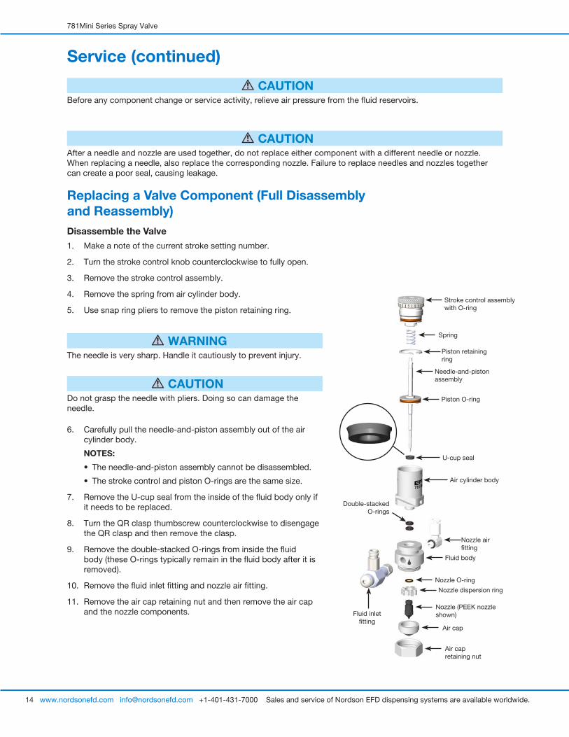
Replacing a Valve Component (Full Disassembly and Reassembly)Disassemble the Valve
1. Make a note of the current stroke setting number.
2. Turn the stroke control knob counterclockwise to fully open.
3. Remove the stroke control assembly.
4. Remove the spring from air cylinder body.
5. Use snap ring pliers to remove the piston retaining ring.
WARNINGThe needle is very sharp. Handle it cautiously to prevent injury.
CAUTIONDo not grasp the needle with pliers. Doing so can damage the needle.
6. Carefully pull the needle-and-piston assembly out of the air cylinder body.
NOTES:
• The needle-and-piston assembly cannot be disassembled.
• The stroke control and piston O-rings are the same size.
7. Remove the U-cup seal from the inside of the fluid body only if it needs to be replaced.
8. Turn the QR clasp thumbscrew counterclockwise to disengage the QR clasp and then remove the clasp.
9. Remove the double-stacked O-rings from inside the fluid body (these O-rings typically remain in the fluid body after it is removed).
10. Remove the fluid inlet fitting and nozzle air fitting.
11. Remove the air cap retaining nut and then remove the air cap and the nozzle components.
Stroke control assembly with O-ring
Air cylinder body
Needle-and-piston assembly
Piston O-ring
Spring
Piston retaining ring
Air cap
Air cap retaining nut
Fluid body
Fluid inlet fitting
Nozzle air fitting
Double-stacked O-rings
U-cup seal
Nozzle (PEEK nozzle shown)
Nozzle O-ring
Nozzle dispersion ring
781Mini Series Spray Valve
15www.nordsonefd.com [email protected] +1-401-431-7000 Sales and service of Nordson EFD dispensing systems are available worldwide.
Replacing a Valve Component (Full Disassembly and Reassembly) (continued)
CAUTIONReplacement parts for 0.01" and 0.03" valves are not interchangeable:
• Use the correct replacement parts based on the size of the valve.
• Do not attempt to convert a 0.01" valve to a 0.03" valve, or vice versa.
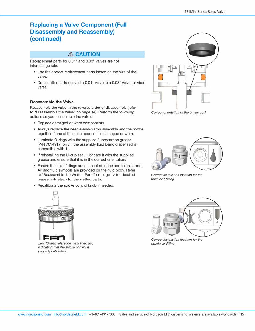
Reassemble the ValveReassemble the valve in the reverse order of disassembly (refer to “Disassemble the Valve” on page 14). Perform the following actions as you reassemble the valve:
• Replace damaged or worn components.
• Always replace the needle-and-piston assembly and the nozzle together if one of these components is damaged or worn.
• Lubricate O-rings with the supplied fluorocarbon grease (P/N 7014917) only if the assembly fluid being dispensed is compatible with it.
• If reinstalling the U-cup seal, lubricate it with the supplied grease and ensure that it is in the correct orientation.
• Ensure that inlet fittings are connected to the correct inlet port. Air and fluid symbols are provided on the fluid body. Refer to “Reassemble the Wetted Parts” on page 12 for detailed reassembly steps for the wetted parts.
• Recalibrate the stroke control knob if needed.
Correct orientation of the U-cup seal
Zero (0) and reference mark lined up, indicating that the stroke control is properly calibrated.
Correct installation location for the fluid inlet fitting
Correct installation location for the nozzle air fitting
781Mini Series Spray Valve
16 www.nordsonefd.com [email protected] +1-401-431-7000 Sales and service of Nordson EFD dispensing systems are available worldwide.
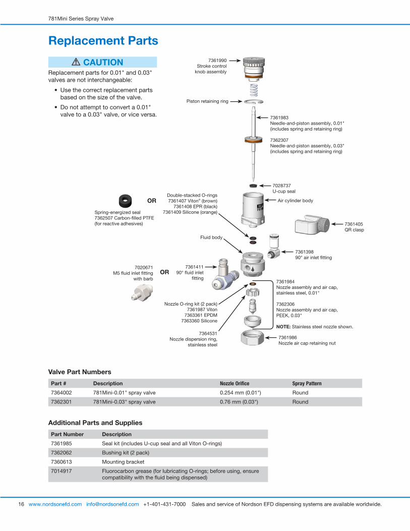
Replacement Parts
7361405QR clasp
Piston retaining ring
Air cylinder body
7361990Stroke control
knob assembly
736139890° air inlet fitting
7361986Nozzle air cap retaining nut
7361984Nozzle assembly and air cap, stainless steel, 0.01"
7362306Nozzle assembly and air cap, PEEK, 0.03"
NOTE: Stainless steel nozzle shown.
Fluid body
736141190° fluid inlet
fittingOR
7361983Needle-and-piston assembly, 0.01" (includes spring and retaining ring)
7362307Needle-and-piston assembly, 0.03" (includes spring and retaining ring)
7028737U-cup seal
Double-stacked O-rings7361407 Viton® (brown)
7361408 EPR (black)7361409 Silicone (orange)
7020671M5 fluid inlet fitting
with barb
Valve Part Numbers
Part # Description Nozzle Orifice Spray Pattern
7364002 781Mini-0.01" spray valve 0.254 mm (0.01") Round
7362301 781Mini-0.03" spray valve 0.76 mm (0.03") Round
Additional Parts and Supplies
Part Number Description
7361985 Seal kit (includes U-cup seal and all Viton O-rings)
7362062 Bushing kit (2 pack)
7360613 Mounting bracket
7014917 Fluorocarbon grease (for lubricating O-rings; before using, ensure compatibility with the fluid being dispensed)
CAUTIONReplacement parts for 0.01" and 0.03" valves are not interchangeable:
• Use the correct replacement parts based on the size of the valve.
• Do not attempt to convert a 0.01" valve to a 0.03" valve, or vice versa.
OR
Spring-energized seal7362507 Carbon-filled PTFE (for reactive adhesives)
7364531Nozzle dispersion ring,
stainless steel
Nozzle O-ring kit (2 pack)7361987 Viton
7363361 EPDM7363360 Silicone
781Mini Series Spray Valve
17www.nordsonefd.com [email protected] +1-401-431-7000 Sales and service of Nordson EFD dispensing systems are available worldwide.
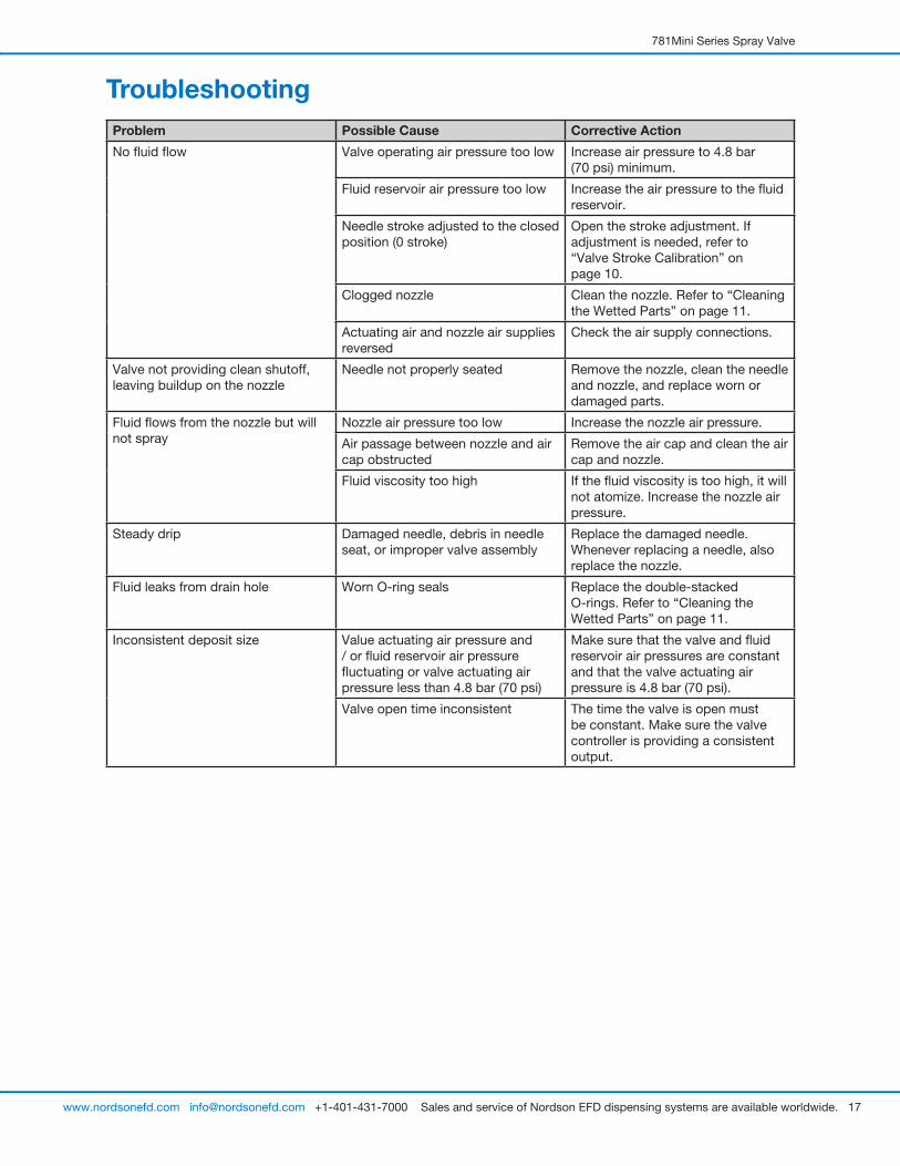
TroubleshootingProblem Possible Cause Corrective Action
No fluid flow Valve operating air pressure too low Increase air pressure to 4.8 bar (70 psi) minimum.
Fluid reservoir air pressure too low Increase the air pressure to the fluid reservoir.
Needle stroke adjusted to the closed position (0 stroke)
Open the stroke adjustment. If adjustment is needed, refer to “Valve Stroke Calibration” on page 10.
Clogged nozzle Clean the nozzle. Refer to “Cleaning the Wetted Parts” on page 11.
Actuating air and nozzle air supplies reversed
Check the air supply connections.
Valve not providing clean shutoff, leaving buildup on the nozzle
Needle not properly seated Remove the nozzle, clean the needle and nozzle, and replace worn or damaged parts.
Fluid flows from the nozzle but will not spray
Nozzle air pressure too low Increase the nozzle air pressure.
Air passage between nozzle and air cap obstructed
Remove the air cap and clean the air cap and nozzle.
Fluid viscosity too high If the fluid viscosity is too high, it will not atomize. Increase the nozzle air pressure.
Steady drip Damaged needle, debris in needle seat, or improper valve assembly
Replace the damaged needle. Whenever replacing a needle, also replace the nozzle.
Fluid leaks from drain hole Worn O-ring seals Replace the double-stacked O-rings. Refer to “Cleaning the Wetted Parts” on page 11.
Inconsistent deposit size Value actuating air pressure and / or fluid reservoir air pressure fluctuating or valve actuating air pressure less than 4.8 bar (70 psi)
Make sure that the valve and fluid reservoir air pressures are constant and that the valve actuating air pressure is 4.8 bar (70 psi).
Valve open time inconsistent The time the valve is open must be constant. Make sure the valve controller is providing a consistent output.
For Nordson EFD sales and service in over 40 countries, contact Nordson EFD or go to www.nordsonefd.com.
Global 800-556-3484; +1-401-431-7000 [email protected]
Europe 00800 7001 7001 [email protected]
Asia China: +86 (21) 3866 9006; [email protected] India: +91 80 4021 3600; [email protected] Japan: +81 03 5762 2760; [email protected] Korea: +82-31-736-8321; [email protected] SEAsia: +65 6796 9522; [email protected]
Viton is a registered trademark of E.I. DuPont. The Wave Design is a trademark of Nordson Corporation. ©2021 Nordson Corporation 7362159 v011721
NORDSON EFD ONE YEAR LIMITED WARRANTY
This Nordson EFD product is warranted for one year from the date of purchase to be free from defects in material and workmanship (but not against damage caused by misuse, abrasion, corrosion, negligence, accident, faulty installation, or by dispensing material incompatible with equipment) when the equipment is installed and operated in accordance with factory recommendations and instructions.
Nordson EFD will repair or replace free of charge any defective part upon authorized return of the part prepaid to our factory during the warranty period. The only exceptions are those parts which normally wear and must be replaced routinely, such as, but not limited to, valve diaphragms, seals, valve heads, needles, and nozzles.
In no event shall any liability or obligation of Nordson EFD arising from this warranty exceed the purchase price of the equipment.
Before operation, the user shall determine the suitability of this product for its intended use, and the user assumes all risk and liability whatsoever in connection therewith. Nordson EFD makes no warranty of merchantability or fitness for a particular purpose. In no event shall Nordson EFD be liable for incidental or consequential damages.
This warranty is valid only when oil-free, clean, dry, filtered air is used, where applicable.