Embed Size (px)
Citation preview
Nokia — Proprietary and confidential.Use pursuant to applicable agreements.
7705 SERVICE AGGREGATION ROUTER | RELEASE 8.0.R7
OAM and Diagnostics Guide
3HE 11013 AAAC TQZZA
Edition: 01
September 2017
OAM and Diagnostics Guide

2
OAM and Diagnostics Guide
3HE 11013 AAAC TQZZA Edition: 01
Nokia is a registered trademark of Nokia Corporation. Other products and company names mentioned herein may be trademarks or tradenames of their respective owners.
The information presented is subject to change without notice. No responsibility is assumed for inaccuracies contained herein.
© 2016-2017 Nokia.
Contains proprietary/trade secret information which is the property of Nokia and must not be made available to, or copied or used by anyone outside Nokia without its written authorization. Not to be used or disclosed except in accordance with applicable agreements.
OAM and Diagnostics Guide
Edition: 01 3HE 11013 AAAC TQZZA 3
Table of Contents
1 Preface...........................................................................................111.1 About This Guide.......................................................................................111.1.1 Audience....................................................................................................121.1.2 List of Technical Publications ....................................................................121.1.3 Technical Support......................................................................................13
2 7705 SAR OAM Configuration Process ......................................15
3 OAM and SAA ...............................................................................173.1 OAM Overview ..........................................................................................183.1.1 ICMP and ICMPv6 Diagnostics .................................................................193.1.1.1 Ping ...........................................................................................................193.1.1.2 Traceroute .................................................................................................193.1.2 Two-Way Active Measurement Protocol ..................................................193.1.2.1 7705 SAR Support for TWAMP Server .....................................................213.1.2.2 Two-Way Active Measurement Protocol Light (TWAMP Light) .................243.1.3 LSP Diagnostics ........................................................................................273.1.3.1 LSP Ping....................................................................................................273.1.3.2 LSP Traceroute .........................................................................................283.1.3.3 LSP Ping and LSP Traceroute for BGP Route Tunnels ............................283.1.3.4 Downstream Detailed Mapping (DDMAP) TLV .........................................303.1.4 SDP Diagnostics........................................................................................373.1.4.1 SDP Ping ...................................................................................................373.1.4.2 SDP MTU Path Discovery .........................................................................383.1.5 Service Diagnostics ...................................................................................383.1.5.1 Service Ping ..............................................................................................393.1.6 VLL Diagnostics.........................................................................................393.1.6.1 VCCV Ping ................................................................................................393.1.6.2 VCCV Trace ..............................................................................................473.1.7 ITU-T Y.1564 Diagnostics .........................................................................473.1.7.1 ITU-T Y.1564 Functionality........................................................................513.1.7.2 ITU-T Y.1564 Protocol Interaction .............................................................513.1.8 VPLS MAC Diagnostics.............................................................................523.1.8.1 MAC Ping ..................................................................................................533.1.8.2 MAC Trace ................................................................................................533.1.8.3 CPE Ping ...................................................................................................543.1.8.4 MAC Populate ...........................................................................................553.1.8.5 MAC Purge ................................................................................................563.1.9 Ethernet OAM Capabilities ........................................................................563.1.9.1 Ethernet OAM Overview............................................................................563.1.9.2 802.1ag and Y.1731 Functional Comparison ............................................603.1.9.3 ETH-CFM Ethernet OAM Tests (802.1ag and Y.1731) .............................613.1.9.4 ITU-T Y.1731 Ethernet Bandwidth Notification (ETH-BN) .........................693.1.9.5 ITU-T Y.1731 Performance Monitoring (PM).............................................723.1.9.6 CFM OAM QoS .........................................................................................76
4
OAM and Diagnostics Guide
3HE 11013 AAAC TQZZA Edition: 01
3.1.9.7 EFM OAM (802.3ah) .................................................................................783.1.10 Ethernet Loopbacks...................................................................................823.1.10.1 Line and Internal Ethernet Loopbacks.......................................................823.1.10.2 CFM Loopbacks for OAM on Ethernet Ports .............................................843.1.11 OAM Propagation to Attachment Circuits..................................................873.1.11.1 ATM Ports..................................................................................................873.1.11.2 T1/E1 TDM Ports.......................................................................................883.1.11.3 Ethernet Ports............................................................................................883.1.11.4 Pseudowire Status Signaling OAM Propagation .......................................883.1.12 LDP Status Signaling.................................................................................883.1.12.1 LDP Status via Label Withdrawal ..............................................................883.1.12.2 LDP Status via TLV ...................................................................................893.1.13 IP Multicast Debugging Tools....................................................................893.1.13.1 Mtrace........................................................................................................893.1.13.2 Mstat..........................................................................................................923.1.13.3 Mrinfo.........................................................................................................923.2 Service Assurance Agent Overview ..........................................................933.2.1 Traceroute Implementation........................................................................933.2.2 SAA Jitter...................................................................................................943.2.3 SAA Ethernet CFM Test Support ..............................................................943.2.3.1 Writing SAA Ethernet CFM Test Results to Accounting Files ...................943.3 Configuring SAA Test Parameters ............................................................963.4 Synthetic Loss Measurement (SLM) .........................................................993.4.1 Configuration Example ............................................................................1013.5 OAM Timestamping.................................................................................1043.6 OAM and SAA Command Reference ......................................................1073.6.1 Command Hierarchies.............................................................................1073.6.1.1 Operational Commands...........................................................................1083.6.1.2 OAM Commands .....................................................................................1083.6.1.3 SAA Commands......................................................................................1173.6.1.4 Show Commands ....................................................................................1193.6.1.5 Clear Commands.....................................................................................1203.6.1.6 Debug Commands...................................................................................1203.6.2 Command Descriptions ...........................................................................1213.6.2.1 OAM and SAA Commands......................................................................1223.6.2.2 Show Commands ....................................................................................2523.6.2.3 Clear Commands.....................................................................................2883.6.2.4 Debug Commands...................................................................................291
4 Mirroring ......................................................................................2934.1 Mirroring Overview ..................................................................................2944.1.1 Mirroring Implementation.........................................................................2954.1.2 Mirror Sources and Destinations .............................................................2964.1.2.1 Local and Remote Mirroring ....................................................................2964.1.2.2 Slicing ......................................................................................................2974.1.3 Mirroring Performance.............................................................................2974.1.4 Mirroring Configuration ............................................................................2984.2 Configuration Notes.................................................................................3004.3 Configuring Mirroring with CLI .................................................................301
OAM and Diagnostics Guide
Edition: 01 3HE 11013 AAAC TQZZA 5
4.3.1 Mirror Configuration Overview.................................................................3014.4 Basic Mirroring Configuration ..................................................................3024.4.1 Mirror Classification Rules.......................................................................3034.5 Common Configuration Tasks .................................................................3054.5.1 Configuring a Local Mirror Service ..........................................................3064.5.2 Configuring SDPs for Mirroring................................................................3074.5.3 Configuring a Remote Mirror Service ......................................................3094.5.4 Pseudowire Redundancy for Mirror Services Configuration
Example...................................................................................................3114.5.5 MC-LAG Setup with ICB for Mirror Services Configuration
Example...................................................................................................3134.6 Service Management Tasks ....................................................................3194.6.1 Modifying a Local Mirrored Service .........................................................3194.6.2 Deleting a Local Mirrored Service ...........................................................3204.6.3 Modifying a Remote Mirrored Service .....................................................3204.6.4 Deleting a Remote Mirrored Service .......................................................3214.7 Mirror Service Configuration Command Reference.................................3234.7.1 Command Hierarchies.............................................................................3234.7.1.1 Mirror Configuration Commands .............................................................3244.7.1.2 Show Commands ....................................................................................3244.7.1.3 Debug Commands...................................................................................3254.7.2 Command Descriptions ...........................................................................3264.7.2.1 Configuration Commands........................................................................3274.7.2.2 Show Commands ....................................................................................3414.7.2.3 Debug Commands...................................................................................344
5 Tools ............................................................................................3475.1 Tools Command Reference.....................................................................3475.1.1 Command Hierarchies.............................................................................3475.1.1.1 Tools Dump Commands..........................................................................3485.1.1.2 Tools Perform Commands.......................................................................3495.1.1.3 Tools ADP Commands............................................................................3515.1.2 Command Descriptions ...........................................................................3525.1.2.1 Tools Generic Commands.......................................................................3535.1.2.2 Tools Dump Commands..........................................................................3545.1.2.3 Tools Perform Commands.......................................................................3875.1.2.4 Tools ADP Commands............................................................................405
7 Standards and Protocol Support ..............................................435

6
OAM and Diagnostics Guide
3HE 11013 AAAC TQZZA Edition: 01
OAM and Diagnostics Guide
Edition: 01 3HE 11013 AAAC TQZZA 7
List of Tables
2 7705 SAR OAM Configuration Process ......................................15Table 1 Configuration Process .............................................................................15
3 OAM and SAA ...............................................................................17Table 2 FEC Stack Change Sub-TLV Operation Types ........................................32Table 3 ITU-T Y.1564 Protocol Interaction ............................................................51Table 4 802.1ag and Y.1731 OAM Functionality Overview ...................................60Table 5 Y.1731 Priority-to-FC Mapping .................................................................77Table 6 Priority Mapping Based on Message Type and MEP Direction ................77Table 7 Loopbacks Supported on Ethernet, DSL, and GPON Ports .....................82Table 8 Location of OAM Timestamping .............................................................104Table 9 Mapping of OAM Tests to Timestamping ..............................................104Table 10 Timestamps per OAM Test ....................................................................106Table 11 Multicast mrinfo Output Fields ................................................................128Table 12 Multicast mstat Output Fields .................................................................131Table 13 Multicast mtrace Output Fields ...............................................................133Table 14 SVC Ping Report Field ..........................................................................139Table 15 Local SDP Message Results .................................................................145Table 16 Remote SDP Message Results ..............................................................146Table 17 P2MP-LSP-Ping Request Packet and Behavior .....................................201Table 18 SDP Ping Response Messages .............................................................203Table 19 Single Response Connectivity ...............................................................204Table 20 ETH-CFM Association Field Descriptions ..............................................253Table 21 ETH-CFM Stack Table Field Descriptions ..............................................255Table 22 ETH-CFM Domain Field Descriptions ....................................................257Table 23 ETH-CFM MEP, Loopback, and Linktrace Field Descriptions ................261Table 24 ETH-CFM MEP Remote MEP Field Descriptions ...................................266Table 25 ETH-CFM MEP ETH-Test Field Descriptions .........................................267Table 26 ETH-CFM MEP Delay Measurement Test Field Descriptions ................268Table 27 ETH-CFM MEP Loss Measurement Test Field Descriptions .................269Table 28 SAA Field Descriptions ..........................................................................271Table 29 TWAMP Server Field Descriptions ........................................................275Table 30 TWAMP Server Prefix Field Descriptions ..............................................278Table 31 Show TWAMP Light Output Fields ........................................................279Table 32 ITU-T Y.1564 Test Head Profile Field Descriptions ................................281Table 33 ITU-T Y.1564 Test Field Descriptions ....................................................284
4 Mirroring ......................................................................................293Table 34 Mirror Source Port Requirements ..........................................................304Table 35 Show Mirror Output Fields ......................................................................342
5 Tools ............................................................................................347Table 36 DHCP Server Persistence Output Fields ................................................359Table 37 Persistence Summary Output Fields ......................................................361Table 38 Service Output Fields .............................................................................366
8
OAM and Diagnostics Guide
3HE 11013 AAAC TQZZA Edition: 01
Table 39 System-Limits Output Fields ...................................................................369Table 40 System-Resources Output Fields ...........................................................370
6 List of Acronyms ........................................................................407Table 41 Acronyms ...............................................................................................407
7 Standards and Protocol Support ..............................................435Table 42 EMC Industrial Standards Compliance ...................................................436Table 43 EMC Regulatory and Customer Standards Compliance ........................437Table 44 Environmental Standards Compliance ...................................................440Table 45 Safety Standards Compliance ................................................................441Table 46 Telecom Interface Compliance ...............................................................443Table 47 Directives, Regional Approvals and Certifications Compliance ..............444
OAM and Diagnostics Guide
Edition: 01 3HE 11013 AAAC TQZZA 9
List of Figures
3 OAM and SAA ...............................................................................17Figure 1 TWAMP Logical Entities (RFC 5357) ........................................................20Figure 2 Typical TWAMP Implementation ...............................................................21Figure 3 7705 SAR as TWAMP Server and Session Reflector ...............................22Figure 4 Target FEC Stack TLV for BGP-Labeled IPv4 Prefix ................................28Figure 5 DDMAP TLV..............................................................................................30Figure 6 FEC Stack Change Sub-TLV.....................................................................32Figure 7 BGP 3107 Tunnel Through LDP FEC .......................................................35Figure 8 VCCV Ping Application..............................................................................40Figure 9 OAM Control Word Format........................................................................40Figure 10 VCCV TLV.................................................................................................41Figure 11 VCCV Ping Over a Multi-Segment Pseudowire.........................................43Figure 12 ITU-T Y.1564 End-to-End Throughput Test ..............................................49Figure 13 Queuing and Policing Points That Impact Throughput ..............................50Figure 14 7705 SAR Ethernet OAM Endpoints .........................................................58Figure 15 ETH-CFM (Dot1ag) Capabilities on the 7705 SAR ...................................59Figure 16 EFM OAM (Dot3ah) Capabilities on the 7705 SAR...................................60Figure 17 Dot1ag Loopback Test ..............................................................................63Figure 18 CFM Loopback on Ethernet Ports .............................................................85Figure 19 SLM Example ..........................................................................................101
4 Mirroring ......................................................................................293Figure 20 Local Mirroring Example..........................................................................298Figure 21 Remote Mirroring Example......................................................................299Figure 22 Local Mirrored Service Tasks ..................................................................305Figure 23 Remote Mirrored Service Tasks ..............................................................306Figure 24 Remote Mirrored Service Tasks ..............................................................309Figure 25 State Engine for Redundant Service to a Redundant Mirror
Service.....................................................................................................311Figure 26 Remote Mirroring of MC-LAG Ports ........................................................313

10
OAM and Diagnostics Guide
3HE 11013 AAAC TQZZA Edition: 01
OAM and Diagnostics Guide Preface
Edition: 01 3HE 11013 AAAC TQZZA 11
1 Preface
1.1 About This Guide
This guide describes Operations, Administration and Management (OAM) and diagnostic tools provided by the 7705 SAR and presents examples to configure and implement various tests.
This document is organized into functional chapters and provides concepts and descriptions of the implementation flow, as well as Command Line Interface (CLI) syntax and command usage.
Note: This manual generically covers Release 8.0 content and may contain some content that will be released in later maintenance loads. Please refer to the 7705 SAR OS 8.0.Rx Software Release Notes, part number 3HE11057000xTQZZA, for information on features supported in each load of the Release 8.0 software.
Note:
As of Release 7.0, support for the following hardware has been deprecated:
• CSMv1
• 7705 SAR-F
• 8-port Ethernet Adapter card, version 1
• 16-port T1/E1 ASAP Adapter card, version 1
These components are no longer recognized in the release.
Preface
12
OAM and Diagnostics Guide
3HE 11013 AAAC TQZZA Edition: 01
1.1.1 Audience
This guide is intended for network administrators who are responsible for configuring the 7705 SAR routers. It is assumed that the network administrators have an understanding of networking principles and configurations. Concepts described in this guide include the following:
• CLI concepts
• operations, administration, and maintenance (OAM) operations
1.1.2 List of Technical Publications
The 7705 SAR documentation set is composed of the following guides:
• 7705 SAR Basic System Configuration Guide
This guide describes basic system configurations and operations.
• 7705 SAR System Management Guide
This guide describes system security and access configurations as well as event logging and accounting logs.
• 7705 SAR Interface Configuration Guide
This guide describes card and port provisioning.
• 7705 SAR Router Configuration Guide
This guide describes logical IP routing interfaces, filtering, and routing policies.
• 7705 SAR MPLS Guide
This guide describes how to configure Multiprotocol Label Switching (MPLS), Resource Reservation Protocol for Traffic Engineering (RSVP-TE), and Label Distribution Protocol (LDP).
• 7705 SAR Services Guide
This guide describes how to configure service parameters such as service access points (SAPs), service destination points (SDPs), customer information, and user services.
• 7705 SAR Quality of Service Guide
This guide describes how to configure Quality of Service (QoS) policy management.
• 7705 SAR Routing Protocols Guide
This guide provides an overview of dynamic routing concepts and describes how to configure them.
OAM and Diagnostics Guide Preface
Edition: 01 3HE 11013 AAAC TQZZA 13
• 7705 SAR OAM and Diagnostics Guide
This guide provides information on Operations, Administration and Maintenance (OAM) tools.
1.1.3 Technical Support
If you purchased a service agreement for your 7705 SAR router and related products from a distributor or authorized reseller, contact the technical support staff for that distributor or reseller for assistance. If you purchased a Nokia service agreement, follow this link to contact a Nokia support representative and to access product manuals and documentation updates:
Product Support Portal

Preface
14
OAM and Diagnostics Guide
3HE 11013 AAAC TQZZA Edition: 01
OAM and Diagnostics Guide 7705 SAR OAM Configuration Process
Edition: 01 3HE 11013 AAAC TQZZA 15
2 7705 SAR OAM Configuration Process
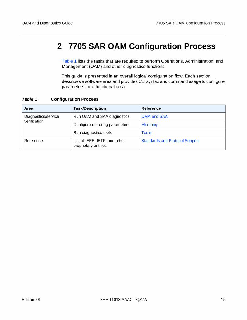
Table 1 lists the tasks that are required to perform Operations, Administration, and Management (OAM) and other diagnostics functions.
This guide is presented in an overall logical configuration flow. Each section describes a software area and provides CLI syntax and command usage to configure parameters for a functional area.
Table 1 Configuration Process
Area Task/Description Reference
Diagnostics/service verification
Run OAM and SAA diagnostics OAM and SAA
Configure mirroring parameters Mirroring
Run diagnostics tools Tools
Reference List of IEEE, IETF, and other proprietary entities
Standards and Protocol Support

7705 SAR OAM Configuration Process
16
OAM and Diagnostics Guide
3HE 11013 AAAC TQZZA Edition: 01
OAM and Diagnostics Guide OAM and SAA
Edition: 01 3HE 11013 AAAC TQZZA 17
3 OAM and SAA
This chapter provides information about the Operations, Administration and Maintenance (OAM) and Service Assurance Agent (SAA) commands available in the CLI for troubleshooting services.
Topics in this chapter include:
• OAM Overview
• Service Assurance Agent Overview
• Configuring SAA Test Parameters
• Synthetic Loss Measurement (SLM)
• OAM Timestamping
• OAM and SAA Command Reference
OAM and SAA
18
OAM and Diagnostics Guide
3HE 11013 AAAC TQZZA Edition: 01
3.1 OAM Overview
Delivery of services requires that a number of operations occur properly and at different levels in the service delivery model. For example, operations—such as the association of packets to a service, VC-labels to a service, and each service to a service tunnel—must be performed properly in the forwarding plane for the service to function properly. In order to verify that a service is operational, a set of in-band, packet-based OAM tools is provided, with the ability to test each of the individual packet operations.
For in-band testing, the OAM packets closely resemble customer packets in order to effectively test the customer's forwarding path, but they are distinguishable from customer packets so that they can be kept within the service provider's network and not get forwarded to the customer.
The suite of OAM diagnostics supplements the basic IP ping and traceroute operations with diagnostics specialized for the different levels in the service delivery model. In addition, there are diagnostics for MPLS LSPs, SDPs, and Services within a service.
This section describes the following topics:
• ICMP and ICMPv6 Diagnostics
• Two-Way Active Measurement Protocol
• LSP Diagnostics
• SDP Diagnostics
• Service Diagnostics
• VLL Diagnostics
• ITU-T Y.1564 Diagnostics
• VPLS MAC Diagnostics
• Ethernet OAM Capabilities
• Ethernet Loopbacks
• OAM Propagation to Attachment Circuits
• LDP Status Signaling
• IP Multicast Debugging Tools
OAM and Diagnostics Guide OAM and SAA
Edition: 01 3HE 11013 AAAC TQZZA 19
3.1.1 ICMP and ICMPv6 Diagnostics
Internet Control Message Protocol (ICMP) is part of the IP suite as defined in RFC 792, Internet Control Message Protocol, for IPv4 and RFC 4443, Internet Control Message Protocol (ICMPv6) for the Internet Protocol Version 6 (IPv6) Specification.
ICMP and ICMPv6 send and receive control and error messages used to manage the behavior of the TCP/IP stack. ICMP and ICMPv6 provide:
• debugging tools and error reporting mechanisms to assist in troubleshooting an IP network
• the ability to send and receive error and control messages to far-end IP entities
3.1.1.1 Ping
Ping is used to determine if there is IP layer connectivity between the 7705 SAR and another node in the network.
The 7705 SAR supports redirection of SGT to egress data queues rather than the default control queue. To redirect ping to a data queue, the ping command includes the fc-queue option, which specifies the queue to be used for servicing the ping packets in the egress direction. All other SGT applications are redirected using the config>router>sgt-qos>application>fc-queue or config>service>vprn>sgt-qos>application>fc-queue command. For more information on SGT redirection, refer to the 7705 SAR Quality of Service Guide, “SGT Redirection”.
3.1.1.2 Traceroute
Traceroute is used to determine the path that an IP packet takes from the 7705 SAR to a specified router.
3.1.2 Two-Way Active Measurement Protocol
The Two-way active measurement protocol (TWAMP) provides a standards-based method to measure the round-trip performance (including the packet loss, delay, and jitter) of IP packets that are transmitted between two devices. TWAMP, which is described in RFC 5357, uses the methodology and architecture of the One-way active measurement protocol (OWAMP) to assess the two-way transmission of IP packets.
OAM and SAA
20
OAM and Diagnostics Guide
3HE 11013 AAAC TQZZA Edition: 01
TWAMP offers advantages for performance monitoring at L3/IP layer because it provides functions that other performance monitoring methods, such as ICMP, lack:
• timestamping for delay and jitter measurements
• high-accuracy timestamping at TX and RX on 7705 SAR nodes for error-free results
• intelligent control plane
There are four logical entities in TWAMP:
• control client—initiates the TWAMP control session and negotiates the security protocols to be used and the tests to be performed with the server
• server—negotiates with the control client request to establish the control session
• session sender—transmits test packets to the session reflector
• session reflector—transmits a packet to the session sender in response to each packet it receives
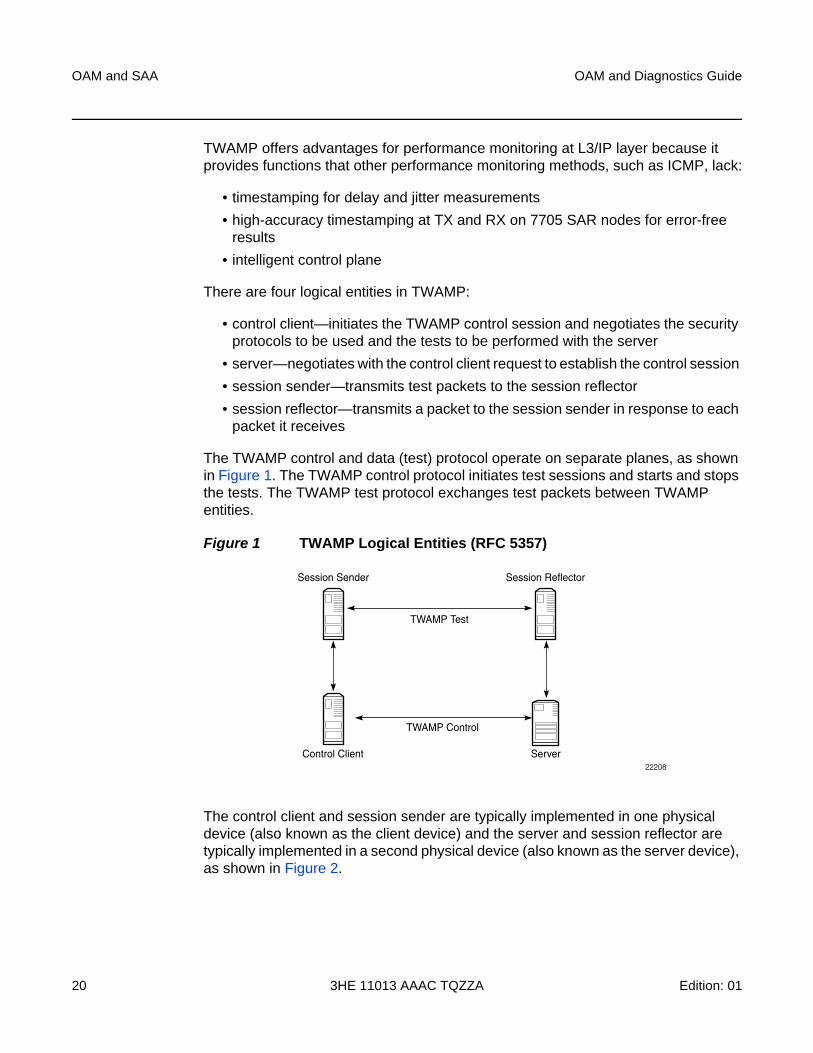
The TWAMP control and data (test) protocol operate on separate planes, as shown in Figure 1. The TWAMP control protocol initiates test sessions and starts and stops the tests. The TWAMP test protocol exchanges test packets between TWAMP entities.
Figure 1 TWAMP Logical Entities (RFC 5357)
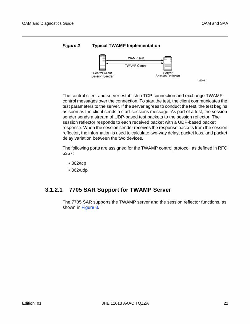
The control client and session sender are typically implemented in one physical device (also known as the client device) and the server and session reflector are typically implemented in a second physical device (also known as the server device), as shown in Figure 2.
22208
Control Client
Session Sender
TWAMP Test
Session Reflector
TWAMP Control
Server
OAM and Diagnostics Guide OAM and SAA
Edition: 01 3HE 11013 AAAC TQZZA 21
Figure 2 Typical TWAMP Implementation
The control client and server establish a TCP connection and exchange TWAMP control messages over the connection. To start the test, the client communicates the test parameters to the server. If the server agrees to conduct the test, the test begins as soon as the client sends a start-sessions message. As part of a test, the session sender sends a stream of UDP-based test packets to the session reflector. The session reflector responds to each received packet with a UDP-based packet response. When the session sender receives the response packets from the session reflector, the information is used to calculate two-way delay, packet loss, and packet delay variation between the two devices.
The following ports are assigned for the TWAMP control protocol, as defined in RFC 5357:
• 862/tcp
• 862/udp
3.1.2.1 7705 SAR Support for TWAMP Server
The 7705 SAR supports the TWAMP server and the session reflector functions, as shown in Figure 3.
22209
TWAMP Test
Control ClientSession Sender
TWAMP Control
ServerSession Reflector
OAM and SAA
22
OAM and Diagnostics Guide
3HE 11013 AAAC TQZZA Edition: 01
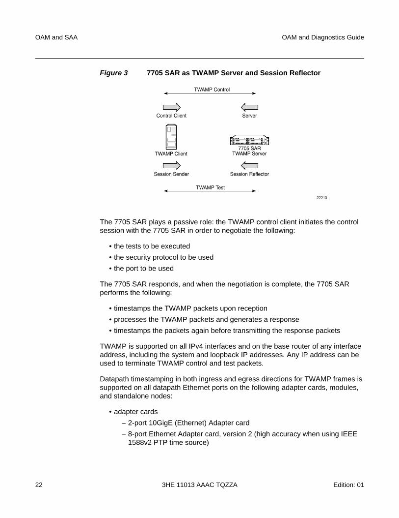
Figure 3 7705 SAR as TWAMP Server and Session Reflector
The 7705 SAR plays a passive role: the TWAMP control client initiates the control session with the 7705 SAR in order to negotiate the following:
• the tests to be executed
• the security protocol to be used
• the port to be used
The 7705 SAR responds, and when the negotiation is complete, the 7705 SAR performs the following:
• timestamps the TWAMP packets upon reception
• processes the TWAMP packets and generates a response
• timestamps the packets again before transmitting the response packets
TWAMP is supported on all IPv4 interfaces and on the base router of any interface address, including the system and loopback IP addresses. Any IP address can be used to terminate TWAMP control and test packets.
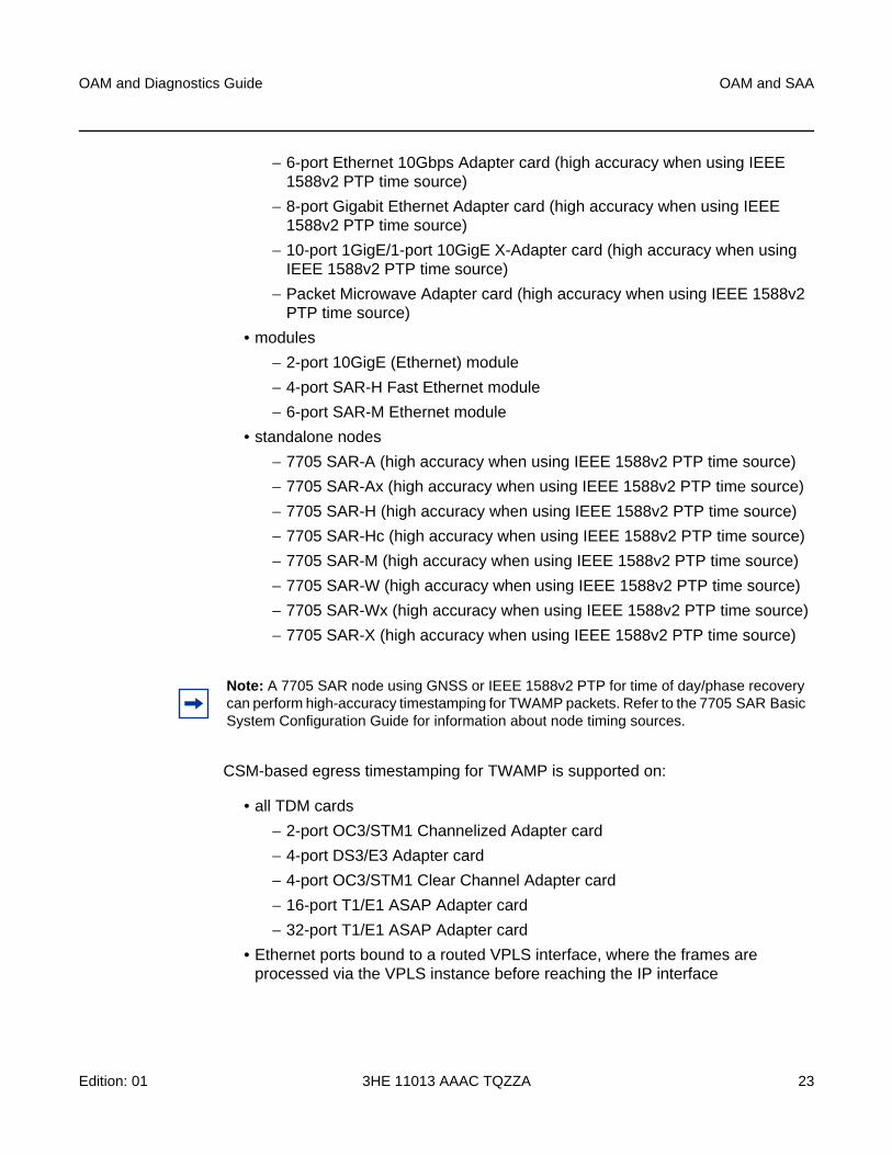
Datapath timestamping in both ingress and egress directions for TWAMP frames is supported on all datapath Ethernet ports on the following adapter cards, modules, and standalone nodes:
• adapter cards
− 2-port 10GigE (Ethernet) Adapter card
− 8-port Ethernet Adapter card, version 2 (high accuracy when using IEEE 1588v2 PTP time source)
22210
7705 SARTWAMP Server
TWAMP Test
TWAMP Client
TWAMP Control
Control Client Server
Session Sender Session Reflector
OAM and Diagnostics Guide OAM and SAA
Edition: 01 3HE 11013 AAAC TQZZA 23
− 6-port Ethernet 10Gbps Adapter card (high accuracy when using IEEE 1588v2 PTP time source)
− 8-port Gigabit Ethernet Adapter card (high accuracy when using IEEE 1588v2 PTP time source)
− 10-port 1GigE/1-port 10GigE X-Adapter card (high accuracy when using IEEE 1588v2 PTP time source)
− Packet Microwave Adapter card (high accuracy when using IEEE 1588v2 PTP time source)
• modules
− 2-port 10GigE (Ethernet) module
− 4-port SAR-H Fast Ethernet module
− 6-port SAR-M Ethernet module
• standalone nodes
− 7705 SAR-A (high accuracy when using IEEE 1588v2 PTP time source)
− 7705 SAR-Ax (high accuracy when using IEEE 1588v2 PTP time source)
− 7705 SAR-H (high accuracy when using IEEE 1588v2 PTP time source)
− 7705 SAR-Hc (high accuracy when using IEEE 1588v2 PTP time source)
− 7705 SAR-M (high accuracy when using IEEE 1588v2 PTP time source)
− 7705 SAR-W (high accuracy when using IEEE 1588v2 PTP time source)
− 7705 SAR-Wx (high accuracy when using IEEE 1588v2 PTP time source)
− 7705 SAR-X (high accuracy when using IEEE 1588v2 PTP time source)
CSM-based egress timestamping for TWAMP is supported on:
• all TDM cards
− 2-port OC3/STM1 Channelized Adapter card
− 4-port DS3/E3 Adapter card
− 4-port OC3/STM1 Clear Channel Adapter card
− 16-port T1/E1 ASAP Adapter card
− 32-port T1/E1 ASAP Adapter card
• Ethernet ports bound to a routed VPLS interface, where the frames are processed via the VPLS instance before reaching the IP interface
Note: A 7705 SAR node using GNSS or IEEE 1588v2 PTP for time of day/phase recovery can perform high-accuracy timestamping for TWAMP packets. Refer to the 7705 SAR Basic System Configuration Guide for information about node timing sources.
OAM and SAA
24
OAM and Diagnostics Guide
3HE 11013 AAAC TQZZA Edition: 01
For information about how to configure the TWAMP server and the TWAMP command hierarchy, see the OAM commands for TWAMP.
The 7705 SAR supports a show>test-oam>twamp>server command that displays information about the TWAMP server configuration and statistics, and the clients associated with each server address prefix. See the Show Commands for more information. The 7705 SAR also supports a dump command that displays statistics for dropped connections, dropped connection states, rejected sessions, and dropped test packets. See Dump Test-OAM Commands for more information.
3.1.2.1.1 Interactions with Ethernet Loopback
Ethernet line loopbacks, being the lower layer functionality, take precedence over TWAMP operations. If an Ethernet port loopback is enabled, all frames including TWAMP frames are looped back. TWAMP frames cannot be processed on the interface until the loopback is released.
3.1.2.1.2 Limitations
The following limitations apply:
• only the unauthenticated mode of TWAMP is supported. Authenticated and encrypted modes are excluded.
• TWAMP does not support redundant HA configurations. During a CSM activity switch, all TWAMP control sessions are dropped and all tests that are in progress are terminated.
3.1.2.2 Two-Way Active Measurement Protocol Light (TWAMP Light)
TWAMP Light is an optional model included in the TWAMP standard RFC 5357, A Two-Way Active Measurement Protocol (TWAMP). TWAMP Light uses the standard TWAMP packet format but provides a simpler approach to gathering ongoing IP delay and synthetic loss performance data for the base router and per-VPRN statistics. Full details are described in Appendix I of RFC 5357.
OAM and Diagnostics Guide OAM and SAA
Edition: 01 3HE 11013 AAAC TQZZA 25
With TWAMP Light, the TWAMP client/server model is replaced with a session controller/responder model. The server, control-client and session-sender role is combined in one host called the controller, and the session-reflector role is in another host called the responder. In general terms, the session controller is the launch point for the TWAMP test packets and the responder reflects the packets.
TWAMP Light maintains the TWAMP test packet exchange but eliminates the TWAMP TCP control connection with local configurations; however, not all negotiated control parameters are replaced with local configurations. The DSCP value in an incoming TWAMP test packet is reflected back to the originator. The incoming TWAMP test packet is classified to a specific FC based on the ingress QoS policy and the dot1p in the reflected packet is determined by the FC to dot1p mapping in the egress QoS policy.
The reflector function is configured under the config>router>twamp-light command hierarchy for base router reflection, and under the config>service>vprn>twamp-light command hierarchy for per-VPRN reflection. The TWAMP Light reflector function is configured per context and must be activated before reflection can occur; the function is not enabled by default for any context. The reflector requires the operator to define the TWAMP Light UDP listening port that identifies the TWAMP Light protocol and to define the prefixes that the reflector will accept as valid sources for a TWAMP Light request.
If the source IP address in the TWAMP Light packet arriving on the responder does not match a configured IP address prefix, the packet is dropped. Multiple prefix entries may be configured per context on the responder. Configured prefixes can be modified without shutting down the reflector function. An inactivity timeout under the config>oam-test>twamp>twamp-light command hierarchy defines the amount of time the reflector will keep the individual reflector sessions active in the absence of test packets.
TWAMP uses a single packet to gather both delay and loss metrics. This means there is special consideration over those approaches that utilize a specific tool per metric type.
TWAMP Light is supported for deployments that use IPv4 or IPv6 addressing, which may each have their own hardware requirements. All IP addressing must be unicast. IPv6 addresses cannot be reserved or link local addresses. Multiple test sessions may be configured between the same source and destination IP endpoints. The 4-tuple lookup (source IP, destination IP, source UDP, destination UDP provides a unique index for each test point.
Note: A 7705 SAR node using GNSS or IEEE 1588v2 PTP for time of day/phase recovery can perform high-accuracy timestamping for TWAMP Light packets.
OAM and SAA
26
OAM and Diagnostics Guide
3HE 11013 AAAC TQZZA Edition: 01
3.1.2.2.1 7705 SAR Support for TWAMP Light Responder
TWAMP Light is supported on the same hardware as TWAMP. See 7705 SAR Support for TWAMP Server.
For information about how to configure the TWAMP Light reflector see the OAM commands for TWAMP Light.
3.1.2.2.2 Interactions with Ethernet Loopback
Ethernet line loopbacks, being the lower layer functionality, take precedence over TWAMP Light operations. If an Ethernet port loopback is enabled, all frames are looped back. Frames cannot be processed on the interface until the loopback is released.
3.1.2.2.3 Limitations
The following limitations apply:
• only the unauthenticated mode of TWAMP is supported
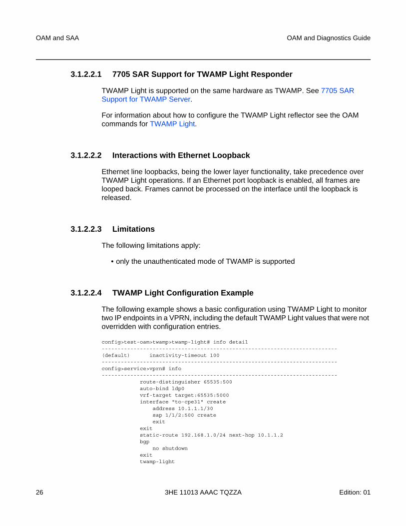
3.1.2.2.4 TWAMP Light Configuration Example
The following example shows a basic configuration using TWAMP Light to monitor two IP endpoints in a VPRN, including the default TWAMP Light values that were not overridden with configuration entries.
config>test-oam>twamp>twamp-light# info detail--------------------------------------------------------------------------(default) inactivity-timeout 100--------------------------------------------------------------------------config>service>vprn# info--------------------------------------------------------------------------
route-distinguisher 65535:500auto-bind ldp0vrf-target target:65535:5000interface "to-cpe31" create
address 10.1.1.1/30sap 1/1/2:500 createexit
exitstatic-route 192.168.1.0/24 next-hop 10.1.1.2bgp
no shutdownexittwamp-light
OAM and Diagnostics Guide OAM and SAA
Edition: 01 3HE 11013 AAAC TQZZA 27
reflector udp-port 64364 createdescription "TWAMP Light reflector VPRN 500"prefix 10.2.1.1/32 create
description "Process only 10.2.1.1 TWAMP Light Packets"exitprefix 172.16.1.0/24 create"
description "Process all 172.16.1.0 TWAMP Light packets"exitno shutdown
exitexitno shutdown
----------------------------------------------
3.1.3 LSP Diagnostics
The 7705 SAR LSP diagnostics are implementations of LSP ping and LSP traceroute based on RFC 4379, Detecting Multi-Protocol Label Switched (MPLS) Data Plane Failures. LSP ping and LSP traceroute are modeled after the ICMP echo request/reply used by ping and traceroute to detect and localize faults in IP networks.
The downstream mapping TLV is used in LSP ping and LSP trace to allow the sender and responder nodes to exchange and validate interface and label stack information for each downstream hop of an LDP FEC or an RSVP LSP and at each hop in an LDP FEC path, RSVP LSP, or BGP-labeled IPv4 route. The 7705 SAR supports two downstream mapping TLVs: the original Downstream Mapping (DSMAP) TLV defined in RFC 4379 and the Downstream Detailed Mapping (DDMAP) TLV defined in RFC 6424.
This section describes the following topics:
• LSP Ping
• LSP Traceroute
• LSP Ping and LSP Traceroute for BGP Route Tunnels
• Downstream Detailed Mapping (DDMAP) TLV
3.1.3.1 LSP Ping
LSP ping, as described in RFC 4379, provides a mechanism to detect data plane failures in MPLS LSPs. For a given FEC, LSP ping verifies whether the packet reaches the egress label edge router (eLER).
OAM and SAA
28
OAM and Diagnostics Guide
3HE 11013 AAAC TQZZA Edition: 01
A 7705 SAR node using GNSS or IEEE 1588v2 PTP for time of day/phase recovery can perform LSP ping tests with high-accuracy timestamping. Refer to the 7705 SAR Basic System Configuration Guide, “Node Timing”, for information about node timing sources.
3.1.3.2 LSP Traceroute
LSP traceroute sends a packet to each transit LSR along a communications path until the far-end router is reached. The path is traced one LSR at a time, where each LSR that receives a traceroute packet replies to the initiating 7705 SAR with a packet that identifies itself. Once the final LSR is identified, the initiating LSR has a list of all LSRs on the path. Like IP traceroute, LSP traceroute is a hop-by-hop operation (that is, LSR by LSR).
Use LSP traceroute to determine the exact litigation of LSP failures.
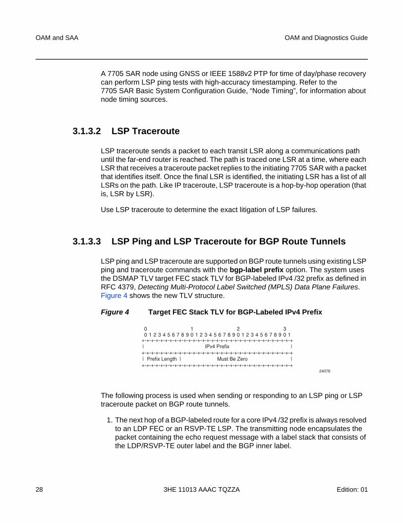
3.1.3.3 LSP Ping and LSP Traceroute for BGP Route Tunnels
LSP ping and LSP traceroute are supported on BGP route tunnels using existing LSP ping and traceroute commands with the bgp-label prefix option. The system uses the DSMAP TLV target FEC stack TLV for BGP-labeled IPv4 /32 prefix as defined in RFC 4379, Detecting Multi-Protocol Label Switched (MPLS) Data Plane Failures. Figure 4 shows the new TLV structure.
Figure 4 Target FEC Stack TLV for BGP-Labeled IPv4 Prefix
The following process is used when sending or responding to an LSP ping or LSP traceroute packet on BGP route tunnels.
1. The next hop of a BGP-labeled route for a core IPv4 /32 prefix is always resolved to an LDP FEC or an RSVP-TE LSP. The transmitting node encapsulates the packet containing the echo request message with a label stack that consists of the LDP/RSVP-TE outer label and the BGP inner label.
24076
+-+-+-+-+-+-+-+-+-+-+-+-+-+-+-+-+-+-+-+-+-+-+-+-+-+-+-+-+-+-+-+-+ | | +-+-+-+-+-+-+-+-+-+-+-+-+-+-+-+-+-+-+-+-+-+-+-+-+-+-+-+-+-+-+-+-+
+-+-+-+-+-+-+-+-+-+-+-+-+-+-+-+-+-+-+-+-+-+-+-+-+-+-+-+-+-+-+-+-+| | |
IPv4 Prefix
Prefix Length Must Be Zero
0 0 1 2 3 4 5 6 7 8 9 0 1 2 3 4 5 6 7 8 9 0 1 2 3 4 5 6 7 8 9 0 1
1 2 3
OAM and Diagnostics Guide OAM and SAA
Edition: 01 3HE 11013 AAAC TQZZA 29
2. If the packet expires on an RSVP-TE or LDP LSR node that does not have context for the BGP-labeled IPv4 /32 prefix, the system must validate the outer label in the stack, and if the validation is successful, it must reply with return code 8 <Label switched at stack-depth <RSC>>.
3. An LSR node that is the next hop for the BGP-labeled IPv4 /32 prefix, as well as the LER node that originated the BGP-labeled IPv4 prefix, have full context for the BGP IPv4 target FEC stack and can thus perform full validation of it.
For more information on BGP route tunnels, refer to the 7705 SAR Routing Protocols Guide, “BGP Route Tunnels”.
3.1.3.3.1 TC Handling on BGP Route Tunnels
A 7705 SAR that process BGP 3107 labels always re-marks the TC bits. Ingress classification is based on the received TC/DSCP bits to FC. Egress re-marking is based on the QoS queue policy.
A 7705 SAR that does not process labels on a BGP route tunnel such as a 7705 SAR acting as an LSR, does not re-mark the TC bits.
3.1.3.3.2 BGP Route Tunnel Traceroute
Labeled-BGP route tunnels pose a challenge to traceroute capability because there are two labels used in the transport layer: an inner BGP label identifying the far-end node and the regular label identifying the next hop for that far end.
Traceroute and TTL monitoring on the 7705 SAR have been enhanced to be able to identify and report every PE, ABR, ASBR, and P node along the path of a Layer 2 or Layer 3 service built partially or wholly over labeled-BGP route tunnels.
Both the MPLS tunnel TTL and the labeled-BGP route tunnel TTL are monitored for TTL expiry, which causes an ICMP TTL expired message to be sourced. Depending on the role of the intermediate nodes along the path, monitoring both TTL values is the most comprehensive way to ensure proper TTL handling.
Note: The 7705 SAR supports only BGP-labeled IPv4 /32 prefixes in LSP ping and LSP trace.
OAM and SAA
30
OAM and Diagnostics Guide
3HE 11013 AAAC TQZZA Edition: 01
3.1.3.3.3 Traceroute TTL for Self-generated Traffic
Depending on how the network is built on elements in the topology, a node along the path might be operating based on the outer MPLS tunnel label or the inner BGP label. In order to ensure that all the nodes along the path are displayed correctly, the 7705 SAR sets the TTL of the outer MPLS transport tunnel and the inner labeled-BGP route tunnel to identical values. The next node is therefore identified and displayed correctly in a traceroute regardless of which label it is operating on.
For a self-generated traffic traceroute, both the MPLS and the labeled-BGP TTLs are set to 1 in order to identify the first node. At the next hop, both TTL values are incremented to 2. This pattern continues at each hop in the path.
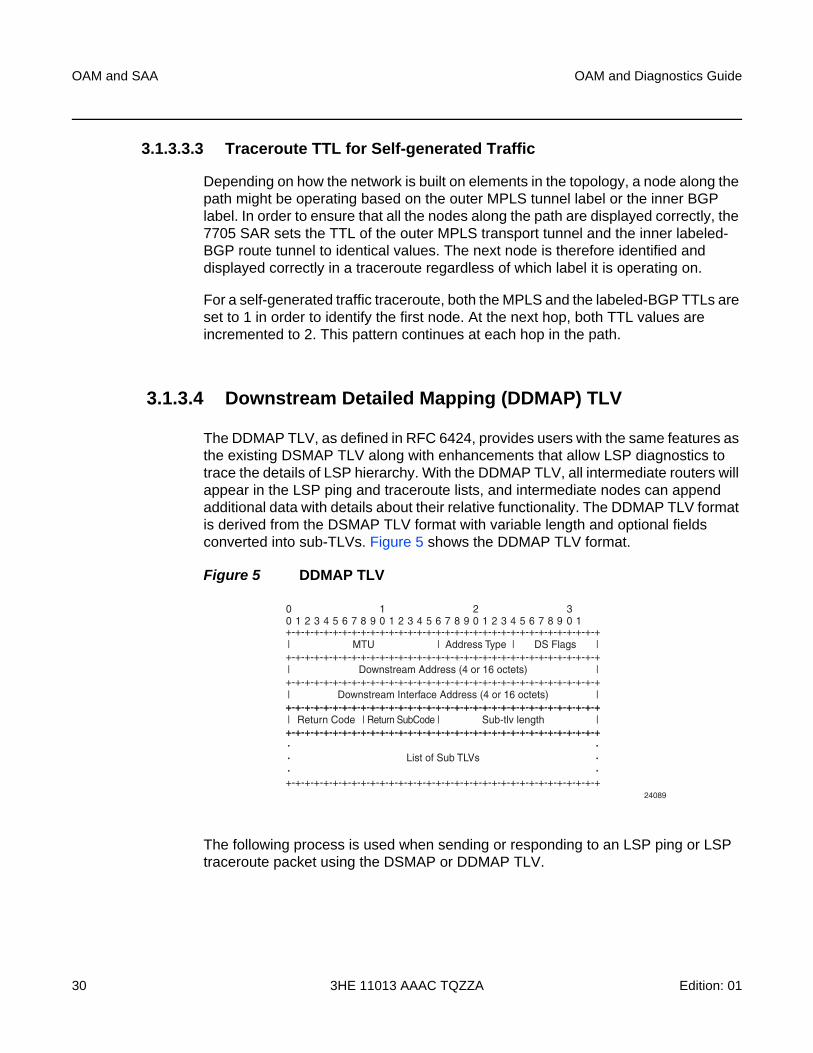
3.1.3.4 Downstream Detailed Mapping (DDMAP) TLV
The DDMAP TLV, as defined in RFC 6424, provides users with the same features as the existing DSMAP TLV along with enhancements that allow LSP diagnostics to trace the details of LSP hierarchy. With the DDMAP TLV, all intermediate routers will appear in the LSP ping and traceroute lists, and intermediate nodes can append additional data with details about their relative functionality. The DDMAP TLV format is derived from the DSMAP TLV format with variable length and optional fields converted into sub-TLVs. Figure 5 shows the DDMAP TLV format.
Figure 5 DDMAP TLV
The following process is used when sending or responding to an LSP ping or LSP traceroute packet using the DSMAP or DDMAP TLV.
24089
+-+-+-+-+-+-+-+-+-+-+-+-+-+-+-+-+-+-+-+-+-+-+-+-+-+-+-+-+-+-+-+-+-+| |||+-+-+-+-+-+-+-+-+-+-+-+-+-+-+-+-+-+-+-+-+-+-+-+-+-+-+-+-+-+-+-+-+-+
+-+-+-+-+-+-+-+-+-+-+-+-+-+-+-+-+-+-+-+-+-+-+-+-+-+-+-+-+-+-+-+-+-+| |
MTU Address Type DS Flags
Downstream Address (4 or 16 octets)
+-+-+-+-+-+-+-+-+-+-+-+-+-+-+-+-+-+-+-+-+-+-+-+-+-+-+-+-+-+-+-+-+-+| |Downstream Interface Address (4 or 16 octets)+-+-+-+-+-+-+-+-+-+-+-+-+-+-+-+-+-+-+-+-+-+-+-+-+-+-+-+-+-+-+-+-+-+
+-+-+-+-+-+-+-+-+-+-+-+-+-+-+-+-+-+-+-+-+-+-+-+-+-+-+-+-+-+-+-+-+-+| | | |Return Code Return SubCode Sub-tlv length+-+-+-+-+-+-+-+-+-+-+-+-+-+-+-+-+-+-+-+-+-+-+-+-+-+-+-+-+-+-+-+-+-+
List of Sub TLVs
+-+-+-+-+-+-+-+-+-+-+-+-+-+-+-+-+-+-+-+-+-+-+-+-+-+-+-+-+-+-+-+-+-+
00 1 2 3 4 5 6 7 8 9 0 1 2 3 4 5 6 7 8 9 0 1 2 3 4 5 6 7 8 9 0 1
1 2 3
OAM and Diagnostics Guide OAM and SAA
Edition: 01 3HE 11013 AAAC TQZZA 31
1. When either the DSMAP TLV or the DDMAP TLV is received in an echo request message, the responder node includes the same type of TLV in the echo reply message with the proper downstream interface information and label stack information.
2. If an echo request message without a DSMAP or DDMAP TLV expires at a node that is not the egress for the target FEC stack, the responder node always includes the DSMAP TLV in the echo reply message. This can occur in the following cases:
a. The user issues an LSP trace from a sender node with a min-ttl value higher than 1 and a max-ttl value lower than the number of hops required to reach the egress of the target FEC stack. This is the sender node behavior when the global configuration or the per-test setting of the DSMAP/DDMAP is set to DSMAP.
b. The user issues an LSP ping from a sender node with a TTL value lower than the number of hops required to reach the egress of the target FEC stack. This is the sender node behavior when the global configuration of the DSMAP/DDMAP is set to DSMAP.
c. If the global configuration or the per-test setting of the DSMAP TLV is set to DDMAP, the sender node includes the DDMAP TLV with the downstream IP address field set to the all-routers multicast address as per Section 3.3 of RFC 4379. The responder node then bypasses the interface and label stack validation and replies with a DDMAP TLV with the correct downstream information for the target FEC stack.
3. A sender node never includes the DSMAP or DDMAP TLV in an lsp-ping message.
The user can globally configure the downstream mapping TLV to be used for all LSP trace and LDP treetrace packets with the configure test-oam mpls-echo-request-downstream-map command. The configured global value becomes the default downstream mapping TLV for all newly created LSP trace and LDP treetrace tests. It has no effect on existing tests and can be overridden on a specific test by setting the downstream-map-tlv parameter in the lsp-trace or ldp-treetrace context.
3.1.3.4.1 Using The DDMAP TLV in LSP Stitching and LSP Hierarchy
The DDMAP TLV provides full validation for a BGP IPv4 label route tunneled over an RSVP LSP or an LDP FEC.
Note: The 7705 SAR does not support LSP stitching.
OAM and SAA
32
OAM and Diagnostics Guide
3HE 11013 AAAC TQZZA Edition: 01
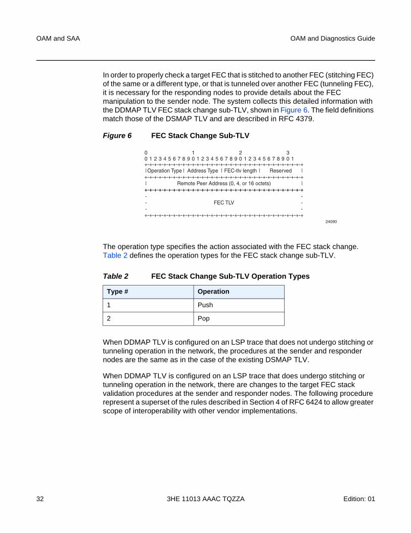
In order to properly check a target FEC that is stitched to another FEC (stitching FEC) of the same or a different type, or that is tunneled over another FEC (tunneling FEC), it is necessary for the responding nodes to provide details about the FEC manipulation to the sender node. The system collects this detailed information with the DDMAP TLV FEC stack change sub-TLV, shown in Figure 6. The field definitions match those of the DSMAP TLV and are described in RFC 4379.
Figure 6 FEC Stack Change Sub-TLV
The operation type specifies the action associated with the FEC stack change. Table 2 defines the operation types for the FEC stack change sub-TLV.
When DDMAP TLV is configured on an LSP trace that does not undergo stitching or tunneling operation in the network, the procedures at the sender and responder nodes are the same as in the case of the existing DSMAP TLV.
When DDMAP TLV is configured on an LSP trace that does undergo stitching or tunneling operation in the network, there are changes to the target FEC stack validation procedures at the sender and responder nodes. The following procedure represent a superset of the rules described in Section 4 of RFC 6424 to allow greater scope of interoperability with other vendor implementations.
Table 2 FEC Stack Change Sub-TLV Operation Types
Type # Operation
1 Push
2 Pop
24090
+-+-+-+-+-+-+-+-+-+-+-+-+-+-+-+-+-+-+-+-+-+-+-+-+-+-+-+-+-+-+-+-+-+| ||||+-+-+-+-+-+-+-+-+-+-+-+-+-+-+-+-+-+-+-+-+-+-+-+-+-+-+-+-+-+-+-+-+-+| |
Operation Type FEC-tlv lengthAddress Type Reserved
Remote Peer Address (0, 4, or 16 octets)+-+-+-+-+-+-+-+-+-+-+-+-+-+-+-+-+-+-+-+-+-+-+-+-+-+-+-+-+-+-+-+-+-++-+-+-+-+-+-+-+-+-+-+-+-+-+-+-+-+-+-+-+-+-+-+-+-+-+-+-+-+-+-+-+-+-+
FEC TLV
+-+-+-+-+-+-+-+-+-+-+-+-+-+-+-+-+-+-+-+-+-+-+-+-+-+-+-+-+-+-+-+-+-+
00 1 2 3 4 5 6 7 8 9 0 1 2 3 4 5 6 7 8 9 0 1 2 3 4 5 6 7 8 9 0 1
1 2 3
OAM and Diagnostics Guide OAM and SAA
Edition: 01 3HE 11013 AAAC TQZZA 33
Responder Node Procedures:
Step 1. As a responder node, the 7705 SAR always inserts the global return code, 3 Replying router is an egress for the FEC at stack-depth <RSC> or the code, 14 See DDMAP TLV for Return Code and Return Subcode.
Step 2. When the responder node inserts a global return code of 3, it does not include a DDMAP TLV.
Step 3. When the responder node includes the DDMAP TLV, it inserts the global return code, 14 See DDMAP TLV for Return Code and Return Subcode. Additionally, the responder node will:
a. on a success response, include a return code of 15 in the DDMAP TLV for each downstream hop that has a FEC stack change sub-TLV
b. on a success response, include a return code, 8 Label switched at stackdepth <RSC> in the DDMAP TLV for each downstream hop if no FEC stack change sub-TLV is present
c. on a failure response, include an appropriate error return code in the DDMAP TLV for each downstream hop
Step 4. A tunneling node indicates that it is pushing a FEC (the tunneling FEC) on top of the target FEC stack TLV by including a FEC stack change sub-TLV in the DDMAP TLV with a FEC operation type value of PUSH. It also includes a return code, 15 Label switched with FEC change. The downstream interface address and downstream IP address fields of the DDMAP TLV are populated for the pushed FEC. The remote peer address field in the FEC stack change sub-TLV is populated with the address of the control plane peer for the pushed FEC. The Label stack sub-TLV provides the full label stack over the downstream interface.
Step 5. A node that is stitching a FEC indicates that it is performing a POP operation for the stitched FEC followed by a PUSH operation for the stitching FEC and potentially one PUSH operation for the transport tunnel FEC. The echo reply message will include two or more FEC stack change sub-TLVs in the DDMAP TLV. It also includes a return code 15 Label switched with FEC change. The downstream interface address and downstream address fields of the DDMAP TLV are populated for the stitching FEC. The remote peer address field in the FEC stack change sub-TLV of type POP is populated with a null value (0.0.0.0). The remote peer address field in the FEC stack change sub-TLV of type PUSH is populated with the address of the control plane peer for the tunneling FEC. The Label stack sub-TLV provides the full label stack over the downstream interface.
Step 6. If the responder node is the egress for one or more FECs in the target FEC Stack, then it must reply with no DDMAP TLV and with a return code 3 Replying router is an egress for the FEC at stack-depth <RSC>. RSC must be set to the depth of the topmost FEC. This operation is iterative.
OAM and SAA
34
OAM and Diagnostics Guide
3HE 11013 AAAC TQZZA Edition: 01
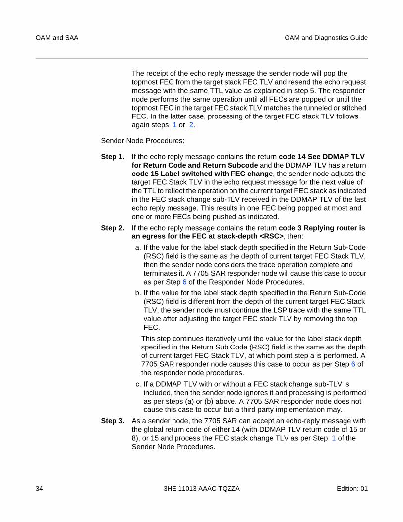
The receipt of the echo reply message the sender node will pop the topmost FEC from the target stack FEC TLV and resend the echo request message with the same TTL value as explained in step 5. The responder node performs the same operation until all FECs are popped or until the topmost FEC in the target FEC stack TLV matches the tunneled or stitched FEC. In the latter case, processing of the target FEC stack TLV follows again steps 1 or 2.
Sender Node Procedures:
Step 1. If the echo reply message contains the return code 14 See DDMAP TLV for Return Code and Return Subcode and the DDMAP TLV has a return code 15 Label switched with FEC change, the sender node adjusts the target FEC Stack TLV in the echo request message for the next value of the TTL to reflect the operation on the current target FEC stack as indicated in the FEC stack change sub-TLV received in the DDMAP TLV of the last echo reply message. This results in one FEC being popped at most and one or more FECs being pushed as indicated.
Step 2. If the echo reply message contains the return code 3 Replying router is an egress for the FEC at stack-depth <RSC>, then:
a. If the value for the label stack depth specified in the Return Sub-Code (RSC) field is the same as the depth of current target FEC Stack TLV, then the sender node considers the trace operation complete and terminates it. A 7705 SAR responder node will cause this case to occur as per Step 6 of the Responder Node Procedures.
b. If the value for the label stack depth specified in the Return Sub-Code (RSC) field is different from the depth of the current target FEC Stack TLV, the sender node must continue the LSP trace with the same TTL value after adjusting the target FEC stack TLV by removing the top FEC.
This step continues iteratively until the value for the label stack depth specified in the Return Sub Code (RSC) field is the same as the depth of current target FEC Stack TLV, at which point step a is performed. A 7705 SAR responder node causes this case to occur as per Step 6 of the responder node procedures.
c. If a DDMAP TLV with or without a FEC stack change sub-TLV is included, then the sender node ignores it and processing is performed as per steps (a) or (b) above. A 7705 SAR responder node does not cause this case to occur but a third party implementation may.
Step 3. As a sender node, the 7705 SAR can accept an echo-reply message with the global return code of either 14 (with DDMAP TLV return code of 15 or 8), or 15 and process the FEC stack change TLV as per Step 1 of the Sender Node Procedures.
OAM and Diagnostics Guide OAM and SAA
Edition: 01 3HE 11013 AAAC TQZZA 35
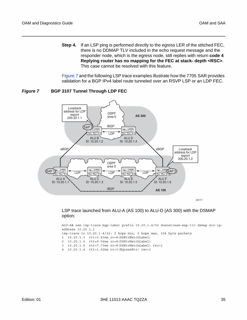
Step 4. If an LSP ping is performed directly to the egress LER of the stitched FEC, there is no DDMAP TLV included in the echo request message and the responder node, which is the egress node, still replies with return code 4 Replying router has no mapping for the FEC at stack- depth <RSC>. This case cannot be resolved with this feature.
Figure 7 and the following LSP trace examples illustrate how the 7705 SAR provides validation for a BGP IPv4 label route tunneled over an RSVP LSP or an LDP FEC.
Figure 7 BGP 3107 Tunnel Through LDP FEC
LSP trace launched from ALU-A (AS 100) to ALU-D (AS 300) with the DSMAP option:
ALU-A# oam lsp-trace bgp-label prefix 10.20.1.4/32 downstream-map-tlv dsmap src-ip-address 10.20.1.1lsp-trace to 10.20.1.4/32: 0 hops min, 0 hops max, 104 byte packets1 10.20.1.3 rtt=3.63ms rc=8(DSRtrMatchLabel)2 10.20.1.5 rtt=9.04ms rc=8(DSRtrMatchLabel)3 10.20.1.6 rtt=7.73ms rc=8(DSRtrMatchLabel) rsc=14 10.20.1.4 rtt=1.62ms rc=3(EgressRtr) rsc=1
OSPFarea 0
LDP
ALU ASI: 10.20.1.1
LDP LDP
ALU FSI: 10.20.1.6
LDPSAP 1
ALU BSI: 10.20.1.2
ALU DSI: 10.20.1.4
iBGP
iBGP
eBGP eBGP
25171
Loopbackaddress for LDP
export200.20.1.2
Loopbackaddress for LDP
export200.20.1.1
OSPFarea 0
ALU CSI: 10.20.1.3
ALU ESI: 10.20.1.5
AS 300
AS 100
SAP 3
SAP 2
OAM and SAA
36
OAM and Diagnostics Guide
3HE 11013 AAAC TQZZA Edition: 01
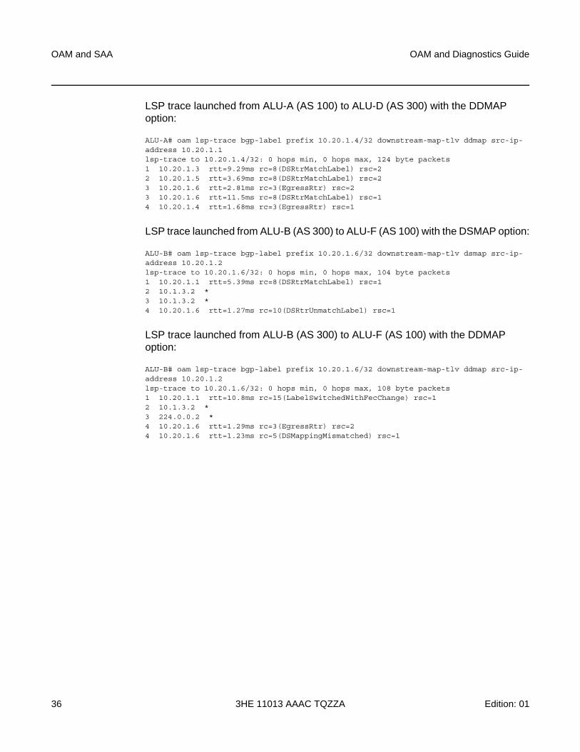
LSP trace launched from ALU-A (AS 100) to ALU-D (AS 300) with the DDMAP option:
ALU-A# oam lsp-trace bgp-label prefix 10.20.1.4/32 downstream-map-tlv ddmap src-ip-address 10.20.1.1lsp-trace to 10.20.1.4/32: 0 hops min, 0 hops max, 124 byte packets1 10.20.1.3 rtt=9.29ms rc=8(DSRtrMatchLabel) rsc=22 10.20.1.5 rtt=3.69ms rc=8(DSRtrMatchLabel) rsc=23 10.20.1.6 rtt=2.81ms rc=3(EgressRtr) rsc=23 10.20.1.6 rtt=11.5ms rc=8(DSRtrMatchLabel) rsc=14 10.20.1.4 rtt=1.68ms rc=3(EgressRtr) rsc=1
LSP trace launched from ALU-B (AS 300) to ALU-F (AS 100) with the DSMAP option:
ALU-B# oam lsp-trace bgp-label prefix 10.20.1.6/32 downstream-map-tlv dsmap src-ip-address 10.20.1.2lsp-trace to 10.20.1.6/32: 0 hops min, 0 hops max, 104 byte packets1 10.20.1.1 rtt=5.39ms rc=8(DSRtrMatchLabel) rsc=12 10.1.3.2 *3 10.1.3.2 *4 10.20.1.6 rtt=1.27ms rc=10(DSRtrUnmatchLabel) rsc=1
LSP trace launched from ALU-B (AS 300) to ALU-F (AS 100) with the DDMAP option:
ALU-B# oam lsp-trace bgp-label prefix 10.20.1.6/32 downstream-map-tlv ddmap src-ip-address 10.20.1.2lsp-trace to 10.20.1.6/32: 0 hops min, 0 hops max, 108 byte packets1 10.20.1.1 rtt=10.8ms rc=15(LabelSwitchedWithFecChange) rsc=12 10.1.3.2 *3 224.0.0.2 *4 10.20.1.6 rtt=1.29ms rc=3(EgressRtr) rsc=24 10.20.1.6 rtt=1.23ms rc=5(DSMappingMismatched) rsc=1
OAM and Diagnostics Guide OAM and SAA
Edition: 01 3HE 11013 AAAC TQZZA 37
3.1.4 SDP Diagnostics
The 7705 SAR SDP diagnostics include:
• SDP Ping
• SDP MTU Path Discovery
3.1.4.1 SDP Ping
SDP ping performs in-band unidirectional or round-trip connectivity tests on SDPs. The SDP ping OAM packets are sent in-band, in the tunnel encapsulation, so it will follow the same path as traffic within the service. The SDP ping response can be received out-of-band in the control plane, or in-band using the data plane for a round-trip test.
For a unidirectional test, SDP ping tests:
• the egress SDP ID encapsulation
• the ability to reach the far-end IP address of the SDP ID within the SDP encapsulation
• the path MTU to the far-end IP address over the SDP ID
• the forwarding class mapping between the near-end SDP ID encapsulation and the far-end tunnel termination
For a round-trip test, SDP ping uses a local egress SDP ID and an expected remote SDP ID. Since SDPs are unidirectional tunnels, the remote SDP ID must be specified and must exist as a configured SDP ID on the far-end 7705 SAR.
SDP round-trip testing is an extension of SDP connectivity testing with the additional ability to test:
• the remote SDP ID encapsulation
• the potential service round-trip time
• the round-trip path MTU
• the round-trip forwarding class mapping
OAM and SAA
38
OAM and Diagnostics Guide
3HE 11013 AAAC TQZZA Edition: 01
3.1.4.2 SDP MTU Path Discovery
In a large network, network devices can support a variety of packet sizes that are transmitted across their interfaces. The largest packet (including headers) can be as large as the Maximum Transmission Unit (MTU). An MTU specifies the largest packet size, measured in octets, that can be transmitted through a network entity. It is important to understand the MTU of the entire path (end-to-end) when provisioning services, especially for VLL services where the service must support the ability to transmit the extra large customer packets.
The Path MTU Discovery tool is a powerful tool that enables service providers to get the exact MTU supported between the service ingress and service termination points, accurate to 1 byte.
3.1.5 Service Diagnostics
The Nokia Service ping feature provides end-to-end connectivity testing for an individual service. Service ping operates at a higher level than the SDP diagnostics in that it verifies an individual service and not the collection of services carried within an SDP.
Note: The sdp-mtu command probes the far-end port using the configured MTU of the near-end port, not the configured MTU of the far-end port. For example, a far-end port that is physically capable of receiving jumbo frames would respond to sdp-mtu probes up to the jumbo frame size, regardless of the configured MTU of the far-end port. This assumes that the intermediate transport network can switch frames of this size.
OAM and Diagnostics Guide OAM and SAA
Edition: 01 3HE 11013 AAAC TQZZA 39
3.1.5.1 Service Ping
Service (SVC) ping is initiated from a 7705 SAR router to verify round-trip connectivity and delay to the far end of the service. Service ping applies to GRE, IP, and MPLS tunnels and tests the following from edge-to-edge:
• tunnel connectivity
• VC label mapping verification
• service existence
• service provisioned parameter verification
• round-trip path verification
• service dynamic configuration verification
3.1.6 VLL Diagnostics
This section describes VCCV (Virtual Circuit Connectivity Verification) ping and VCCV trace, the VLL diagnostic capabilities for the 7705 SAR.
3.1.6.1 VCCV Ping
VCCV ping is used to check the connectivity (in-band) of a VLL. It checks that the destination (target) PE is the egress point for the Layer 2 FEC. It provides a cross-check between the data plane and the control plane. It is in-band, meaning that the VCCV ping message is sent using the same encapsulation and along the same path as user packets in that VLL. This is equivalent to the LSP ping for a VLL service. VCCV ping reuses an LSP ping message format and can be used to test a VLL configured over an MPLS, GRE, or IP SDP.
A 7705 SAR node using GNSS or IEEE 1588v2 PTP for time of day/phase recovery can perform VCCV ping tests with high-accuracy timestamping. Refer to the 7705 SAR Basic System Configuration Guide, “Node Timing”, for information about node timing sources.
Note: By default, service ping uses GRE encapsulation.
OAM and SAA
40
OAM and Diagnostics Guide
3HE 11013 AAAC TQZZA Edition: 01
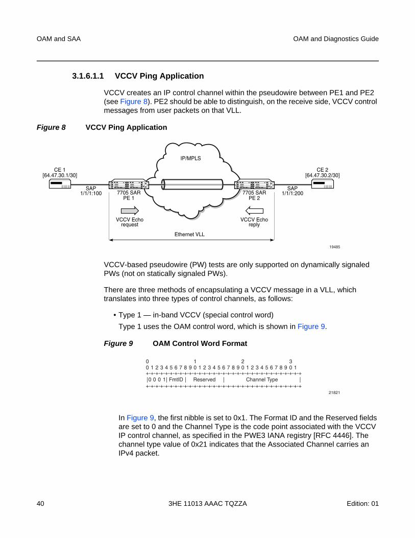
3.1.6.1.1 VCCV Ping Application
VCCV creates an IP control channel within the pseudowire between PE1 and PE2 (see Figure 8). PE2 should be able to distinguish, on the receive side, VCCV control messages from user packets on that VLL.
Figure 8 VCCV Ping Application
VCCV-based pseudowire (PW) tests are only supported on dynamically signaled PWs (not on statically signaled PWs).
There are three methods of encapsulating a VCCV message in a VLL, which translates into three types of control channels, as follows:
• Type 1 — in-band VCCV (special control word)
Type 1 uses the OAM control word, which is shown in Figure 9.
Figure 9 OAM Control Word Format
In Figure 9, the first nibble is set to 0x1. The Format ID and the Reserved fields are set to 0 and the Channel Type is the code point associated with the VCCV IP control channel, as specified in the PWE3 IANA registry [RFC 4446]. The channel type value of 0x21 indicates that the Associated Channel carries an IPv4 packet.
19485
IP/MPLS
Ethernet VLL
VCCV Echorequest
7705 SARPE 1
SAP1/1/1:100
CE 1[64.47.30.1/30]
SAP1/1/1:2007705 SAR
PE 2
CE 2[64.47.30.2/30]
VCCV Echoreply
21821
+-+-+-+-+-+-+-+-+-+-+-+-+-+-+-+-+-+-+-+-+-+-+-+-+-+-+-+-+-+-+-+-+
+-+-+-+-+-+-+-+-+-+-+-+-+-+-+-+-+-+-+-+-+-+-+-+-+-+-+-+-+-+-+-+-+0| | | | |0 0 1 FmtID Reserved Channel Type
00 1 2 3 4 5 6 7 8 9 0 1 2 3 4 5 6 7 8 9 0 1 2 3 4 5 6 7 8 9 0 1
1 2 3
OAM and Diagnostics Guide OAM and SAA
Edition: 01 3HE 11013 AAAC TQZZA 41
The use of the OAM control word assumes that the draft-martini control word is also used for the user packets. This means that if the control word is optional for a VLL and is not configured, the 7705 SAR PE node will only advertise the router alert label as the CC capability in the Label Mapping message.
This method is supported by the 7705 SAR.
• Type 2 — out-of-band VCCV (router alert above the service label)
The 7705 SAR uses the router alert label immediately above the VC label to identify the VCCV ping message. This method has a drawback in that if ECMP is applied to the outer LSP label, such as the transport label, the VCCV message will not follow the same path as the user packets. This effectively means it will not troubleshoot the appropriate path.
This method is supported by the 7705 SAR when a 7750 SR node acts as an LSR in the core of the network. If a 7705 SAR acts as an LSR in the core of the network, the VCCV type 2 message will instead follow the data path.
• Type 3 — TTL expiry VCCV (service label TTL = 1 and special control word)
This method is not supported by the 7705 SAR.
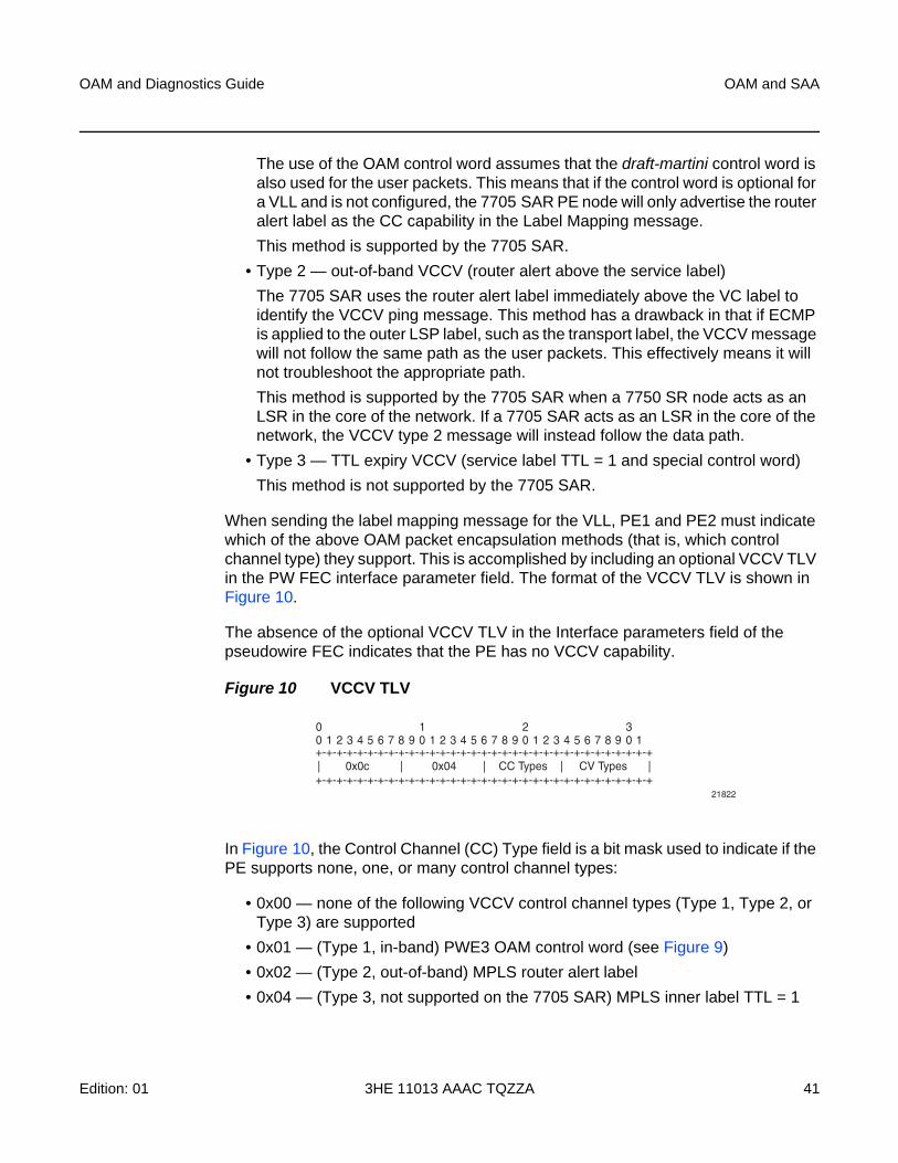
When sending the label mapping message for the VLL, PE1 and PE2 must indicate which of the above OAM packet encapsulation methods (that is, which control channel type) they support. This is accomplished by including an optional VCCV TLV in the PW FEC interface parameter field. The format of the VCCV TLV is shown in Figure 10.
The absence of the optional VCCV TLV in the Interface parameters field of the pseudowire FEC indicates that the PE has no VCCV capability.
Figure 10 VCCV TLV
In Figure 10, the Control Channel (CC) Type field is a bit mask used to indicate if the PE supports none, one, or many control channel types:
• 0x00 — none of the following VCCV control channel types (Type 1, Type 2, or Type 3) are supported
• 0x01 — (Type 1, in-band) PWE3 OAM control word (see Figure 9)
• 0x02 — (Type 2, out-of-band) MPLS router alert label
• 0x04 — (Type 3, not supported on the 7705 SAR) MPLS inner label TTL = 1
21822
+-+-+-+-+-+-+-+-+-+-+-+-+-+-+-+-+-+-+-+-+-+-+-+-+-+-+-+-+-+-+-+-+
+-+-+-+-+-+-+-+-+-+-+-+-+-+-+-+-+-+-+-+-+-+-+-+-+-+-+-+-+-+-+-+-+| | | | |0x0c 0x04 CC Types CV Types
00 1 2 3 4 5 6 7 8 9 0 1 2 3 4 5 6 7 8 9 0 1 2 3 4 5 6 7 8 9 0 1
1 2 3
OAM and SAA
42
OAM and Diagnostics Guide
3HE 11013 AAAC TQZZA Edition: 01
If both PE nodes support more than one of the CC types, then a 7705 SAR PE will make use of the CC type with the lowest type value. For instance, OAM control word (0x01) will be used in preference to the MPLS router alert label (0x02).
The Connectivity Verification (CV) Type field is a bit mask used to indicate the specific type of VCCV packets to be sent over the VCCV control channel. The possible values supported on the 7705 SAR are:
• 0x00 — none of the following VCCV packet types are supported
• 0x02 — LSP ping
This value (0x02) is used in the VCCV ping application and applies to a VLL over an MPLS, GRE, or IP SDP.
A VCCV ping is an LSP echo request message as defined in RFC 4379. It contains a Layer 2 FEC stack TLV in which it must include the sub-TLV type 10 FEC 128 pseudowire. It also contains a field that indicates to the destination PE which reply mode to use:
• do not reply
This mode is supported by the 7705 SAR.
• reply by an IPv4 UDP packet
This mode is supported by the 7705 SAR.
• reply via an IPv4 UDP packet with router alert
This mode is not supported by the 7705 SAR.
• reply by application-level control channel
This mode sends the reply message in-band over the pseudowire from PE2 to PE1. PE2 will encapsulate the echo reply message using the CC type negotiated with PE1.
This mode is supported by the 7705 SAR.
The VCCV ping reply has the same format as an LSP echo reply message as defined in RFC 4379. The message is sent via the reply mode requested by PE1. The return codes supported are the same as those currently supported in the 7705 SAR LSP ping capability.
Note: Do not confuse this mode, which sets the router alert bit in the IP header, with the CC type that makes use of the router alert label.
OAM and Diagnostics Guide OAM and SAA
Edition: 01 3HE 11013 AAAC TQZZA 43
The VCCV ping feature is in addition to the service ping OAM feature that can be used to test a service between 7705 SAR nodes. The VCCV ping feature can test connectivity of a VLL with any third-party node that is compliant with RFC 5085.
3.1.6.1.2 VCCV Ping in a Multi-Segment Pseudowire
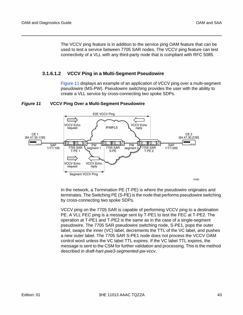
Figure 11 displays an example of an application of VCCV ping over a multi-segment pseudowire (MS-PW). Pseudowire switching provides the user with the ability to create a VLL service by cross-connecting two spoke SDPs.
Figure 11 VCCV Ping Over a Multi-Segment Pseudowire
In the network, a Termination PE (T-PE) is where the pseudowire originates and terminates. The Switching PE (S-PE) is the node that performs pseudowire switching by cross-connecting two spoke SDPs.
VCCV ping on the 7705 SAR is capable of performing VCCV ping to a destination PE. A VLL FEC ping is a message sent by T-PE1 to test the FEC at T-PE2. The operation at T-PE1 and T-PE2 is the same as in the case of a single-segment pseudowire. The 7705 SAR pseudowire switching node, S-PE1, pops the outer label, swaps the inner (VC) label, decrements the TTL of the VC label, and pushes a new outer label. The 7705 SAR S-PE1 node does not process the VCCV OAM control word unless the VC label TTL expires. If the VC label TTL expires, the message is sent to the CSM for further validation and processing. This is the method described in draft-hart-pwe3-segmented-pw-vccv.
19486
IP/MPLS
E2E VCCV Ping
Segment VCCV Ping
VCCV Echorequest
7705 SART-PE 1
SAP1/1/1:100
PWsegment 1
PWsegment 2
CE 1[64.47.30.1/30]
SAP1/1/1:2007705 SAR
S-PE7705 SAR
T-PE 2
CE 2[64.47.30.2/30]
VCCV Echoreply
VCCV Echorequest
VCCV Echoreply

OAM and SAA
44
OAM and Diagnostics Guide
3HE 11013 AAAC TQZZA Edition: 01
The originator of the VCCV ping message does not need to be a T-PE node; it can be an S-PE node. The destination of the VCCV ping message can also be an S-PE node. When an S-PE node receives a VCCV ping echo request destined for itself, it sends an IP-routed reply. VCCV trace can trace the entire path of a pseudowire with a single command issued at the T-PE. This is equivalent to LSP trace and is an iterative process, where T-PE1 sends successive VCCV ping messages while incrementing the TTL value, starting from TTL=1. The procedure for each iteration is the same. Each node in which the VC label TTL expires checks the FEC and replies with the FEC to the downstream S-PE or T-PE node. The process is terminated when the reply is sent from the T-PE2 node or when a timeout occurs.
3.1.6.1.3 Automated VCCV Trace Capability for Multi-Segment Pseudowire
Although tracing of the MS-PW path is possible using the methods explained in the VCCV Ping section, these require multiple manual iterations and that require the FEC of the last pseudowire segment to the target T-PE/S-PE already be known at the node originating the echo request message for each iteration. This mode of operation is referred to as a “ping” mode.
The automated VCCV trace can trace the entire path of a pseudowire with a single command issued at the T-PE or at an S-PE. This is equivalent to LSP trace and is an iterative process by which the ingress T-PE or T-PE sends successive VCCV ping messages with incrementing TTL values, starting from TTL=1.
The method is described in draft-hart-pwe3-segmented-pw-vccv, VCCV Extensions for Segmented Pseudo-Wire, and is pending acceptance by the PWE3 working group. In each iteration, the source T-PE or S-PE builds the MPLS echo request message in a way similar to VCCV Ping. The first message with TTL=1 will have the next-hop S-PE T-LDP session source address in the Remote PE Address field in the pseudowire FEC TLV. Each S-PE that terminates and processes the message will include the FEC 128 TLV corresponding to the pseudowire segment to its downstream node, in the MPLS echo reply message. The inclusion of the FEC TLV in the echo reply message is allowed according to RFC 4379, Detecting Multi-Protocol Label Switched (MPLS) Data Plane Failures.
The source T-PE or S-PE then sends the next echo reply message with TTL=2 to test the next-next hop for the MS-PW. It copies the FEC TLV it received in the echo reply message into the new echo request message. The process is terminated when the reply is sent from the egress T-PE node or when a timeout occurs. If specified, the max-ttl parameter in the vccv-trace command will stop on SPE before reaching T-PE.
OAM and Diagnostics Guide OAM and SAA
Edition: 01 3HE 11013 AAAC TQZZA 45
The results of VCCV trace can be displayed for a fewer number of pseudowire segments of the end-to-end MS-PW path. In this case, the min-ttl and max-ttl parameters are configured accordingly. However, the T-PE/S-PE node will still probe all hops up to the min-ttl value in order to correctly build the FEC of the desired subset of segments.
This method does not require the use of the downstream mapping TLV in the echo request and echo reply messages.
3.1.6.1.4 VCCV for Static Pseudowire Segments
MS-PW is supported with a mix of static and signaled pseudowire segments. However, VCCV ping and VCCV trace are not allowed if any segment of the MS-PW is static. Users cannot test a static segment or contiguous signaled segments of the MS-PW. VCCV ping and VCCV trace are not supported in static-to-dynamic configurations.
3.1.6.1.5 VCCV for MS-PW and Pseudowire Redundancy
VCCV is supported on S-PE nodes configured for MS-PW and PW redundancy. In this case, S-PE terminates the in-band or out-of-band (IP-routed) VCCV ping (echo reply) and can generate VCCV ping (echo request) toward the dynamic section of the PW segment.
To configure an S-PE for MS-PW and pseudowire redundancy, an explicit endpoint is required to configure the service. Only one explicit endpoint is supported. The first PW segment must be configured with a static inner label under an implicit endpoint. The second PW segment can be created as either a redundant or non-redundant PW using the explicit endpoint.
On S-PE nodes configured for MS-PW and PW redundancy, each segment of the PW can be configured with its own independent control word. The control word of the dynamic segment does not have to match the control word of the static segment for traffic to flow. The control word is automatically inserted or removed from the packets as they are switched from one segment to the other based on the control word configuration for each segment.
Note: A VLL service is in MS-PW and PW redundancy mode as long as there is one PW segment with an explicit endpoint configured.
OAM and SAA
46
OAM and Diagnostics Guide
3HE 11013 AAAC TQZZA Edition: 01
From an OAM diagnostic perspective, only Type-1 VCCV is supported for the dynamic MS-PW segment, which means that the PW segment must be configured with the control word option. In this mode, the ability to support VCCVs is signaled through the label message and the optional VCCV TLV toward the dynamic segment on the S-PE. The S-PE terminates all VCCV packets arriving on the dynamic segment, then extracts them towards the CSM.
3.1.6.1.6 Detailed VCCV Trace Operation
In Figure 11, a trace can be performed on the MS-PW originating from T-PE1 by a single operational command. The following process occurs:
1. T-PE 1 sends a VCCV echo request with TTL set to 1 and a FEC 128 containing the pseudowire information of the first segment (pseudowire1 between T-PE 1 and S-PE) to S-PE for validation.
2. S-PE validates the echo request with the FEC 128. Since it is a switching point between the first and second segment, it builds an echo reply with a return code of 8 and includes the FEC 128 of the second segment (pseudowire2 between S-PE and T-PE 2) and sends the echo reply back to T-PE 1.
3. T-PE 1 builds a second VCCV echo request based on the FEC 128 in the echo reply from the S-PE. It increments the TTL and sends the next echo request out to T-PE 2. The VCCV echo request packet is switched at the S-PE datapath and forwarded to the next downstream segment without any involvement from the control plane.
4. T-PE 2 receives and validates the echo request with the FEC 128 of the pseudowire2 from TPE 1. Since T-PE 2 is the destination node or the egress node of the MS-PW, it replies to T-PE1 with an echo reply with a return code of 3 (egress router) and no FEC 128 is included.
5. T-PE 1 receives the echo reply from T-PE 2. T-PE 1 is made aware that T-PE 2 is the destination of the MS-PW because the echo reply does not contain the FEC 128 and because its return code is 3. The trace process is completed.
OAM and Diagnostics Guide OAM and SAA
Edition: 01 3HE 11013 AAAC TQZZA 47
3.1.6.2 VCCV Trace
VCCV trace is similar to LSP trace. VCCV trace is used to trace the entire path of a pseudowire (PW) with a single command.
VCCV trace is useful in multi-segment PW (MS-PW) applications where a single PW traverses one or more switched PEs (S-PEs). VCCV trace is an iterative process by which the initiating terminating PE (T-PE) sends successive VCCV ping messages, each message having an incrementing TTL value, starting from TTL=1. The procedure for each iteration is the same as that for VCCV-ping, where each node in which the VC label TTL expires will check the FEC and reply with the FEC to the downstream S-PE or far-end T-PE. The process is terminated when the reply is from the far-end T-PE or when a timeout occurs.
The results of a VCCV trace can be displayed for a fewer number of pseudowire segments of the end-to-end MS-PW path. In this case, the min-ttl and max-ttl parameters should be configured accordingly. However, the T-PE or S-PE will still probe all hops up to the min-ttl value in order to correctly build the FEC of the desired subset of segments.
3.1.7 ITU-T Y.1564 Diagnostics
The 7705 SAR supports the ITU-T Y.1564 feature for throughput and bandwidth testing of Ethernet point-to-point virtual circuits. ITU-T Y.1564 includes, but also improves and standardizes, the RFC 2544 testing process.
ITU-T Y.1564 is supported on second-generation Ethernet ports in access mode in conjunction with 16-priority scheduling, on the following:
• 7705 SAR-A
• 7705 SAR-Ax
• 7705 SAR-H (not supported on the 4-port SAR-H Fast Ethernet module)
• 7705 SAR-Hc
• 7705 SAR-M
• 7705 SAR-W
• 7705 SAR-Wx
• 8-port Gigabit Ethernet Adapter card
• 10-port 1GigE X-Adapter card (in 10-port 1GigE mode)
• Packet Microwave Adapter card
OAM and SAA
48
OAM and Diagnostics Guide
3HE 11013 AAAC TQZZA Edition: 01
ITU-T Y.1564 is supported on third-generation Ethernet ports in access mode in conjunction with 4-priority scheduling, on the following:
• 7705 SAR-X
• 6-port Ethernet 10Gbps Adapter card
For information on card and platform generations, refer to the 7705 SAR Interface Configuration Guide, “Evolution of Ethernet Adapter Cards, Modules, and Platforms”.
In a traditional hub and spoke network model, traffic is terminated on edge routers and aggregation hubs, which also perform bandwidth and throughput tests. In a flat, seamless, MPLS network, edge routers and aggregation hubs provide only forwarding and switching and cannot be used for service testing as they do not terminate traffic. ITU-T Y.1564 is crucial in these types of networks because it provides the 7705 SAR edge nodes with the ability to run a complete validation of Ethernet SLAs. The 7705 SAR generates RFC 2544 test frames, up to the desired rate, and sends them through the SAP of the service to test its performance. The far-end nodes must also offer per-service loopback capabilities, with the epipe>sap>loopback command, to return the traffic to the source node for test analysis and reporting.
Figure 12 shows a network with service endpoints where throughput tests are required.
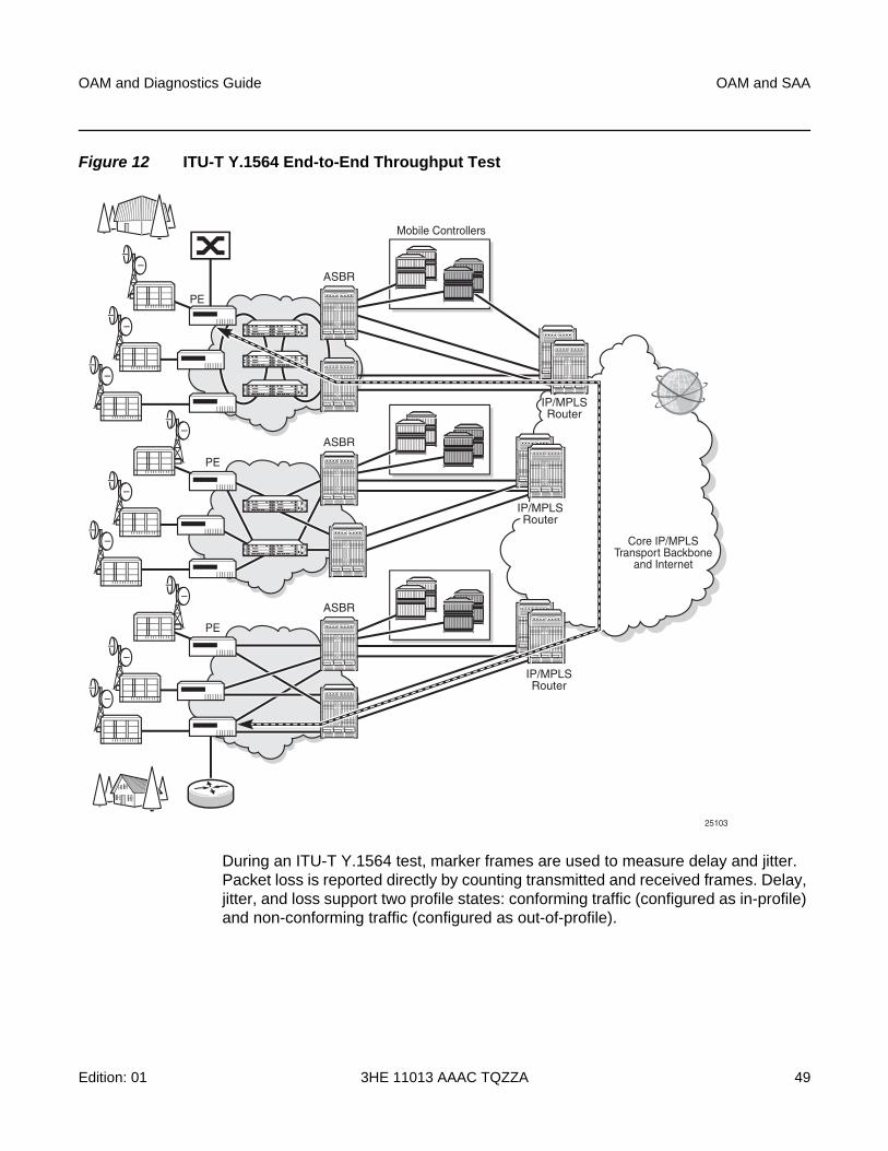
OAM and Diagnostics Guide OAM and SAA
Edition: 01 3HE 11013 AAAC TQZZA 49
Figure 12 ITU-T Y.1564 End-to-End Throughput Test
During an ITU-T Y.1564 test, marker frames are used to measure delay and jitter. Packet loss is reported directly by counting transmitted and received frames. Delay, jitter, and loss support two profile states: conforming traffic (configured as in-profile) and non-conforming traffic (configured as out-of-profile).
Mobile Controllers
ASBR
IP/MPLSRouter
IP/MPLSRouter
PE
Core IP/MPLSTransport Backbone
and Internet
IP/MPLSRouter
ASBR
PE
ASBR
PE
25103
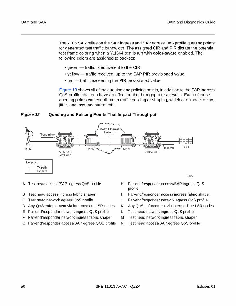
OAM and SAA
50
OAM and Diagnostics Guide
3HE 11013 AAAC TQZZA Edition: 01
The 7705 SAR relies on the SAP ingress and SAP egress QoS profile queuing points for generated test traffic bandwidth. The assigned CIR and PIR dictate the potential test frame coloring when a Y.1564 test is run with color-aware enabled. The following colors are assigned to packets:
• green — traffic is equivalent to the CIR
• yellow — traffic received, up to the SAP PIR provisioned value
• red — traffic exceeding the PIR provisioned value
Figure 13 shows all of the queuing and policing points, in addition to the SAP ingress QoS profile, that can have an effect on the throughput test results. Each of these queuing points can contribute to traffic policing or shaping, which can impact delay, jitter, and loss measurements.
Figure 13 Queuing and Policing Points That Impact Throughput
Metro EthernetNetwork
25104
MEN BSCBTS MEN7705 SARTestHead
7705 SAR
E F GDDA B C
J I HKKN M L
Transmitter
Receiver
Rx pathTx path
Legend:
A Test head access/SAP ingress QoS profile H Far-end/responder access/SAP ingress QoS profile
B Test head access ingress fabric shaper I Far-end/responder access ingress fabric shaper
C Test head network egress QoS profile J Far-end/responder network egress QoS profile
D Any QoS enforcement via intermediate LSR nodes K Any QoS enforcement via intermediate LSR nodes
E Far-end/responder network ingress QoS profile L Test head network ingress QoS profile
F Far-end/responder network ingress fabric shaper M Test head network ingress fabric shaper
G Far-end/responder access/SAP egress QOS profile N Test head access/SAP egress QoS profile
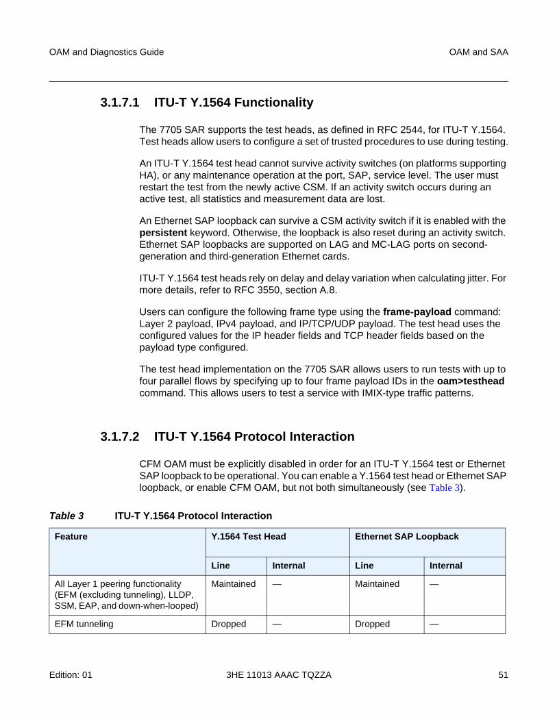
OAM and Diagnostics Guide OAM and SAA
Edition: 01 3HE 11013 AAAC TQZZA 51
3.1.7.1 ITU-T Y.1564 Functionality
The 7705 SAR supports the test heads, as defined in RFC 2544, for ITU-T Y.1564. Test heads allow users to configure a set of trusted procedures to use during testing.
An ITU-T Y.1564 test head cannot survive activity switches (on platforms supporting HA), or any maintenance operation at the port, SAP, service level. The user must restart the test from the newly active CSM. If an activity switch occurs during an active test, all statistics and measurement data are lost.
An Ethernet SAP loopback can survive a CSM activity switch if it is enabled with the persistent keyword. Otherwise, the loopback is also reset during an activity switch. Ethernet SAP loopbacks are supported on LAG and MC-LAG ports on second-generation and third-generation Ethernet cards.
ITU-T Y.1564 test heads rely on delay and delay variation when calculating jitter. For more details, refer to RFC 3550, section A.8.
Users can configure the following frame type using the frame-payload command: Layer 2 payload, IPv4 payload, and IP/TCP/UDP payload. The test head uses the configured values for the IP header fields and TCP header fields based on the payload type configured.
The test head implementation on the 7705 SAR allows users to run tests with up to four parallel flows by specifying up to four frame payload IDs in the oam>testhead command. This allows users to test a service with IMIX-type traffic patterns.
3.1.7.2 ITU-T Y.1564 Protocol Interaction
CFM OAM must be explicitly disabled in order for an ITU-T Y.1564 test or Ethernet SAP loopback to be operational. You can enable a Y.1564 test head or Ethernet SAP loopback, or enable CFM OAM, but not both simultaneously (see Table 3).
Table 3 ITU-T Y.1564 Protocol Interaction
Feature Y.1564 Test Head Ethernet SAP Loopback
Line Internal Line Internal
All Layer 1 peering functionality (EFM (excluding tunneling), LLDP, SSM, EAP, and down-when-looped)
Maintained — Maintained —
EFM tunneling Dropped — Dropped —
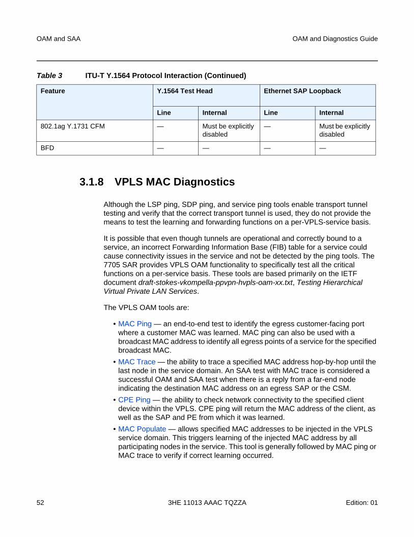
OAM and SAA
52
OAM and Diagnostics Guide
3HE 11013 AAAC TQZZA Edition: 01
3.1.8 VPLS MAC Diagnostics
Although the LSP ping, SDP ping, and service ping tools enable transport tunnel testing and verify that the correct transport tunnel is used, they do not provide the means to test the learning and forwarding functions on a per-VPLS-service basis.
It is possible that even though tunnels are operational and correctly bound to a service, an incorrect Forwarding Information Base (FIB) table for a service could cause connectivity issues in the service and not be detected by the ping tools. The 7705 SAR provides VPLS OAM functionality to specifically test all the critical functions on a per-service basis. These tools are based primarily on the IETF document draft-stokes-vkompella-ppvpn-hvpls-oam-xx.txt, Testing Hierarchical Virtual Private LAN Services.
The VPLS OAM tools are:
• MAC Ping — an end-to-end test to identify the egress customer-facing port where a customer MAC was learned. MAC ping can also be used with a broadcast MAC address to identify all egress points of a service for the specified broadcast MAC.
• MAC Trace — the ability to trace a specified MAC address hop-by-hop until the last node in the service domain. An SAA test with MAC trace is considered a successful OAM and SAA test when there is a reply from a far-end node indicating the destination MAC address on an egress SAP or the CSM.
• CPE Ping — the ability to check network connectivity to the specified client device within the VPLS. CPE ping will return the MAC address of the client, as well as the SAP and PE from which it was learned.
• MAC Populate — allows specified MAC addresses to be injected in the VPLS service domain. This triggers learning of the injected MAC address by all participating nodes in the service. This tool is generally followed by MAC ping or MAC trace to verify if correct learning occurred.
802.1ag Y.1731 CFM — Must be explicitly disabled
— Must be explicitly disabled
BFD — — — —
Table 3 ITU-T Y.1564 Protocol Interaction (Continued)
Feature Y.1564 Test Head Ethernet SAP Loopback
Line Internal Line Internal
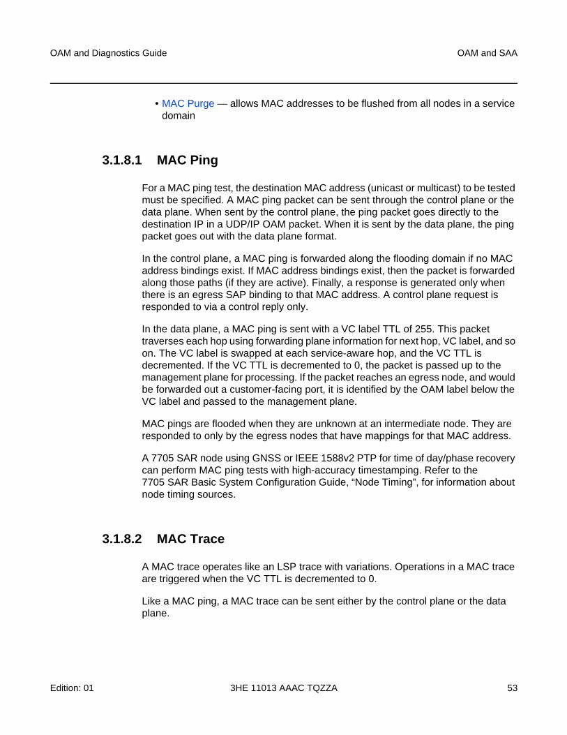
OAM and Diagnostics Guide OAM and SAA
Edition: 01 3HE 11013 AAAC TQZZA 53
• MAC Purge — allows MAC addresses to be flushed from all nodes in a service domain
3.1.8.1 MAC Ping
For a MAC ping test, the destination MAC address (unicast or multicast) to be tested must be specified. A MAC ping packet can be sent through the control plane or the data plane. When sent by the control plane, the ping packet goes directly to the destination IP in a UDP/IP OAM packet. When it is sent by the data plane, the ping packet goes out with the data plane format.
In the control plane, a MAC ping is forwarded along the flooding domain if no MAC address bindings exist. If MAC address bindings exist, then the packet is forwarded along those paths (if they are active). Finally, a response is generated only when there is an egress SAP binding to that MAC address. A control plane request is responded to via a control reply only.
In the data plane, a MAC ping is sent with a VC label TTL of 255. This packet traverses each hop using forwarding plane information for next hop, VC label, and so on. The VC label is swapped at each service-aware hop, and the VC TTL is decremented. If the VC TTL is decremented to 0, the packet is passed up to the management plane for processing. If the packet reaches an egress node, and would be forwarded out a customer-facing port, it is identified by the OAM label below the VC label and passed to the management plane.
MAC pings are flooded when they are unknown at an intermediate node. They are responded to only by the egress nodes that have mappings for that MAC address.
A 7705 SAR node using GNSS or IEEE 1588v2 PTP for time of day/phase recovery can perform MAC ping tests with high-accuracy timestamping. Refer to the 7705 SAR Basic System Configuration Guide, “Node Timing”, for information about node timing sources.
3.1.8.2 MAC Trace
A MAC trace operates like an LSP trace with variations. Operations in a MAC trace are triggered when the VC TTL is decremented to 0.
Like a MAC ping, a MAC trace can be sent either by the control plane or the data plane.
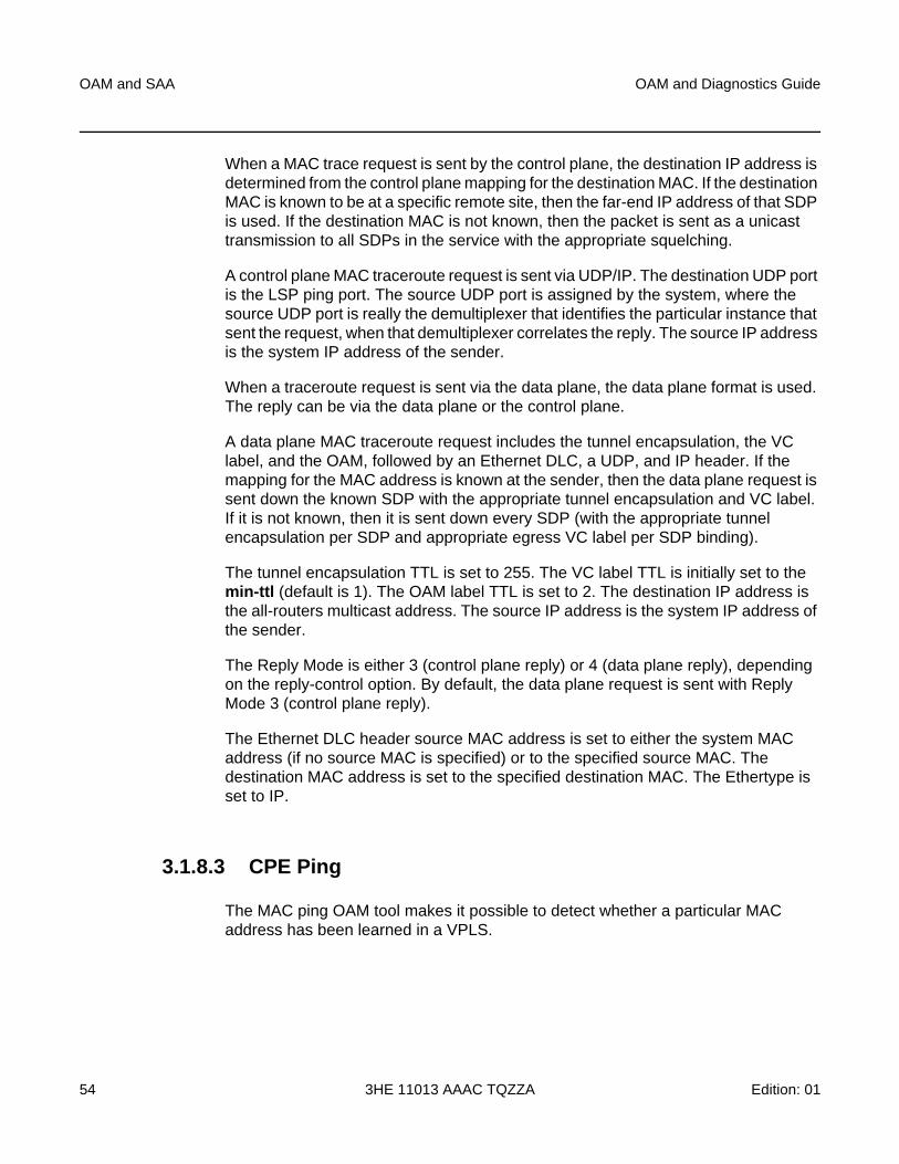
OAM and SAA
54
OAM and Diagnostics Guide
3HE 11013 AAAC TQZZA Edition: 01
When a MAC trace request is sent by the control plane, the destination IP address is determined from the control plane mapping for the destination MAC. If the destination MAC is known to be at a specific remote site, then the far-end IP address of that SDP is used. If the destination MAC is not known, then the packet is sent as a unicast transmission to all SDPs in the service with the appropriate squelching.
A control plane MAC traceroute request is sent via UDP/IP. The destination UDP port is the LSP ping port. The source UDP port is assigned by the system, where the source UDP port is really the demultiplexer that identifies the particular instance that sent the request, when that demultiplexer correlates the reply. The source IP address is the system IP address of the sender.
When a traceroute request is sent via the data plane, the data plane format is used. The reply can be via the data plane or the control plane.
A data plane MAC traceroute request includes the tunnel encapsulation, the VC label, and the OAM, followed by an Ethernet DLC, a UDP, and IP header. If the mapping for the MAC address is known at the sender, then the data plane request is sent down the known SDP with the appropriate tunnel encapsulation and VC label. If it is not known, then it is sent down every SDP (with the appropriate tunnel encapsulation per SDP and appropriate egress VC label per SDP binding).
The tunnel encapsulation TTL is set to 255. The VC label TTL is initially set to the min-ttl (default is 1). The OAM label TTL is set to 2. The destination IP address is the all-routers multicast address. The source IP address is the system IP address of the sender.
The Reply Mode is either 3 (control plane reply) or 4 (data plane reply), depending on the reply-control option. By default, the data plane request is sent with Reply Mode 3 (control plane reply).
The Ethernet DLC header source MAC address is set to either the system MAC address (if no source MAC is specified) or to the specified source MAC. The destination MAC address is set to the specified destination MAC. The Ethertype is set to IP.
3.1.8.3 CPE Ping
The MAC ping OAM tool makes it possible to detect whether a particular MAC address has been learned in a VPLS.
OAM and Diagnostics Guide OAM and SAA
Edition: 01 3HE 11013 AAAC TQZZA 55
The cpe-ping command extends this capability and can detect end-station IP addresses inside a VPLS. A CPE ping for a specific destination IP address within a VPLS will be translated to a MAC ping towards a broadcast MAC address. Upon receiving such a MAC ping, each peer PE within the VPLS context will trigger an ARP request for the specific IP address. The PE receiving a response to this ARP request will report back to the requesting 7705 SAR. Operators are encouraged to use the source IP address of 0.0.0.0 in order to prevent the provider’s IP address from being learned by the CE.
3.1.8.4 MAC Populate
MAC populate is used to send a message through the flooding domain to learn a MAC address as if a customer packet with that source MAC address had flooded the domain from that ingress point in the service. This allows the provider to craft a learning history and engineer packets in a particular way to test forwarding plane correctness.
The MAC populate request is sent with a VC TTL of 1, which means that it is received at the forwarding plane at the first hop and passed directly up to the management plane. The packet is then responded to by populating the MAC address in the forwarding plane, like a conventional learn, although the MAC will be an OAM-type MAC in the FIB to distinguish it from customer MAC addresses.
This packet is then taken by the control plane and flooded out the flooding domain (squelching appropriately, the sender and other paths that would be squelched in a typical flood).
This controlled population of the FIB is very important to manage the expected results of an OAM test. The same functions are available by sending the OAM packet as a UDP/IP OAM packet. It is then forwarded to each hop and the management plane has to do the flooding.
Options for MAC populate are to force the MAC in the table to type OAM (in case it already existed as dynamic or static or as an OAM-induced learning with some other binding), to prevent new dynamic learning to over-write the existing OAM MAC entry, or to allow customer packets with this MAC to either ingress or egress the network while still using the OAM MAC entry.
Finally, an option to flood the MAC populate request causes each upstream node to learn the MAC, for example, to populate the local FIB with an OAM MAC entry, and to flood the request along the data plane using the flooding domain.
An age can be provided to age a particular OAM MAC after a different interval than other MACs in a FIB.
OAM and SAA
56
OAM and Diagnostics Guide
3HE 11013 AAAC TQZZA Edition: 01
3.1.8.5 MAC Purge
MAC purge is used to clear the FIBs of any learned information for a particular MAC address. This allows an operator to perform a controlled OAM test without learning induced by customer packets. In addition to clearing the FIB of a particular MAC address, the purge can also indicate to the control plane not to allow further learning from customer packets. This allows the FIB to be clean and be populated only via a MAC populate request.
MAC purge follows the same flooding mechanism as the MAC populate. A UDP/IP version of this command is also available that does not follow the forwarding notion of the flooding domain, but rather the control plane behavior of it.
3.1.9 Ethernet OAM Capabilities
The 7705 SAR supports Ethernet OAM capabilities, as described in the following sections:
• Ethernet OAM Overview
• 802.1ag and Y.1731 Functional Comparison
• ETH-CFM Ethernet OAM Tests (802.1ag and Y.1731)
• ITU-T Y.1731 Ethernet Bandwidth Notification (ETH-BN)
• ITU-T Y.1731 Performance Monitoring (PM)
• CFM OAM QoS
• EFM OAM (802.3ah)
3.1.9.1 Ethernet OAM Overview
The 7705 SAR supports the following Ethernet OAM capabilities:
• Ethernet Connectivity Fault Management (ETH-CFM) — for network layer OAM according to IEEE 802.1ag (dot1ag) and ITU Y.1731 standards, including loopback (LB), linktrace (LT), continuity check (CC), and remote defect indication (RDI). “Network layer” refers to an end-to-end context across a network.
ITU-T Y.1731 provides functional enhancements to 802.1ag ETH-CFM, including alarm indication signals (AIS) and Ethernet signal tests (ETH-Test).
See ETH-CFM Ethernet OAM Tests (802.1ag and Y.1731).
OAM and Diagnostics Guide OAM and SAA
Edition: 01 3HE 11013 AAAC TQZZA 57
• Ethernet Bandwidth Notification (ETH-BN) – when enabled on a port, the egress rate may be dynamically altered based on the available bandwidth indicated by the ETH-BN server.
See ITU-T Y.1731 Ethernet Bandwidth Notification (ETH-BN).
• Performance Monitoring (PM) — PM according to the ITU-T Y.1731 standard, including delay measurements (DM), delay variation measurements (DV), and loss measurements (LM)
See ITU-T Y.1731 Performance Monitoring (PM).
• Ethernet First Mile (EFM) OAM — for the transport layer OAM according to IEEE 802.3ah (dot3ah) standards. “Transport layer” refers to a point-to-point link context or transport hop.
See EFM OAM (802.3ah).
Ethernet OAM capabilities on the 7705 SAR are similar to the OAM capabilities offered in SONET/SDH networks and include loopback tests to verify end-to-end connectivity, test pattern generation (and response) to verify error-free operation, and alarm message generation in case of fault conditions to ensure that the far end is notified of the failure.
Ethernet OAM configurations are maintained across Control and Switching module (CSM) switchovers.
3.1.9.1.1 Ethernet OAM Usage Examples
Figure 14 illustrates the complementary use of dot3ah and dot1ag to locate points of failure along a route from BTS to BSC. Since dot1ag and Y.1731 have similar functions, only dot1ag is discussed in order to simplify the explanation.
In Figure 14, from the IP/MPLS (network) layer perspective, the 7705 SAR looks as though it is connected directly to the 7750 SR. From the Ethernet (transport) layer perspective, the route passes through many ports and nodes, where each port or node is a potential point of failure. These failure points cannot be detected using IP/MPLS OAM capabilities (that is, using ETH-CFM (dot1ag)). However, they can be detected using EFM OAM (dot3ah) capabilities.
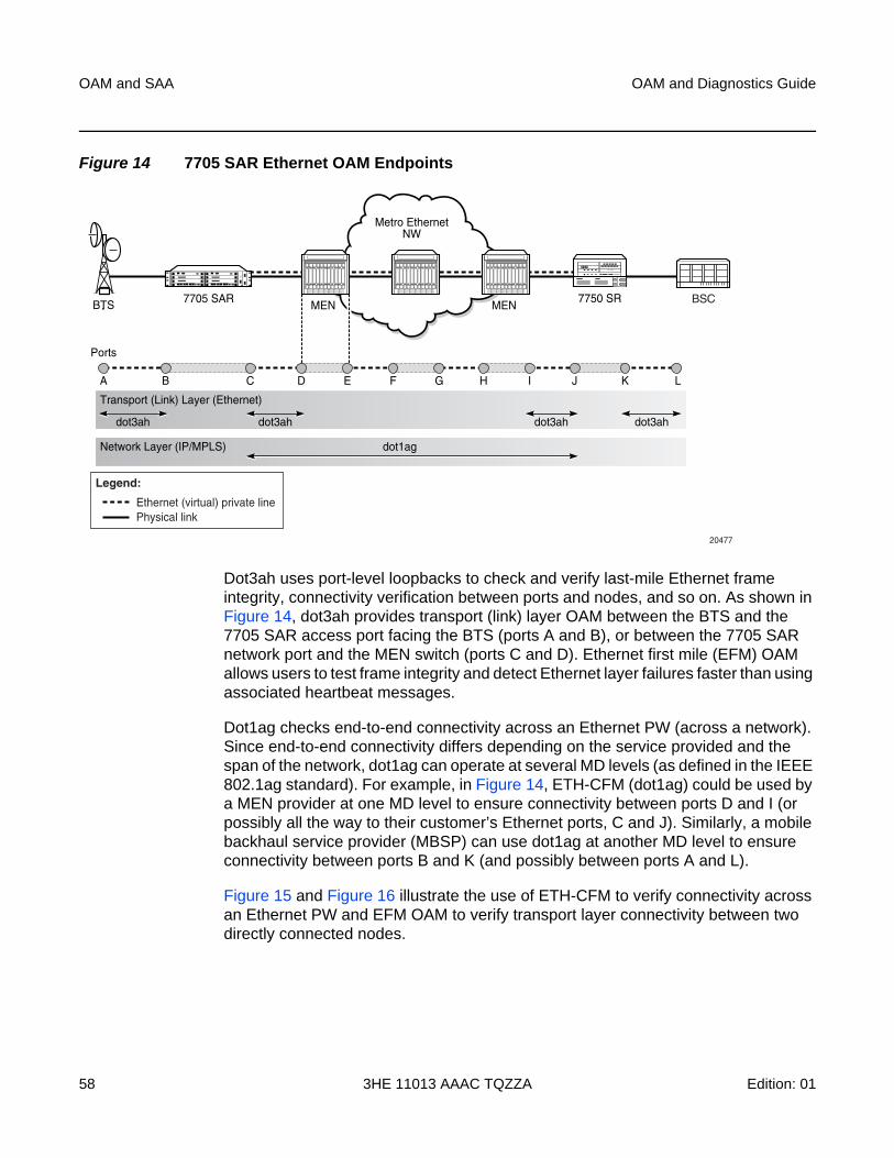
OAM and SAA
58
OAM and Diagnostics Guide
3HE 11013 AAAC TQZZA Edition: 01
Figure 14 7705 SAR Ethernet OAM Endpoints
Dot3ah uses port-level loopbacks to check and verify last-mile Ethernet frame integrity, connectivity verification between ports and nodes, and so on. As shown in Figure 14, dot3ah provides transport (link) layer OAM between the BTS and the 7705 SAR access port facing the BTS (ports A and B), or between the 7705 SAR network port and the MEN switch (ports C and D). Ethernet first mile (EFM) OAM allows users to test frame integrity and detect Ethernet layer failures faster than using associated heartbeat messages.
Dot1ag checks end-to-end connectivity across an Ethernet PW (across a network). Since end-to-end connectivity differs depending on the service provided and the span of the network, dot1ag can operate at several MD levels (as defined in the IEEE 802.1ag standard). For example, in Figure 14, ETH-CFM (dot1ag) could be used by a MEN provider at one MD level to ensure connectivity between ports D and I (or possibly all the way to their customer’s Ethernet ports, C and J). Similarly, a mobile backhaul service provider (MBSP) can use dot1ag at another MD level to ensure connectivity between ports B and K (and possibly between ports A and L).
Figure 15 and Figure 16 illustrate the use of ETH-CFM to verify connectivity across an Ethernet PW and EFM OAM to verify transport layer connectivity between two directly connected nodes.
Metro EthernetNW
BTS 7705 SARMEN BSC7750 SR
MEN
A
Ports
Network Layer (IP/MPLS) dot1ag
B C D E F G H I J K L
Transport (Link) Layer (Ethernet)
dot3ah dot3ah dot3ah dot3ah
20477
Ethernet (virtual) private linePhysical link
Legend:
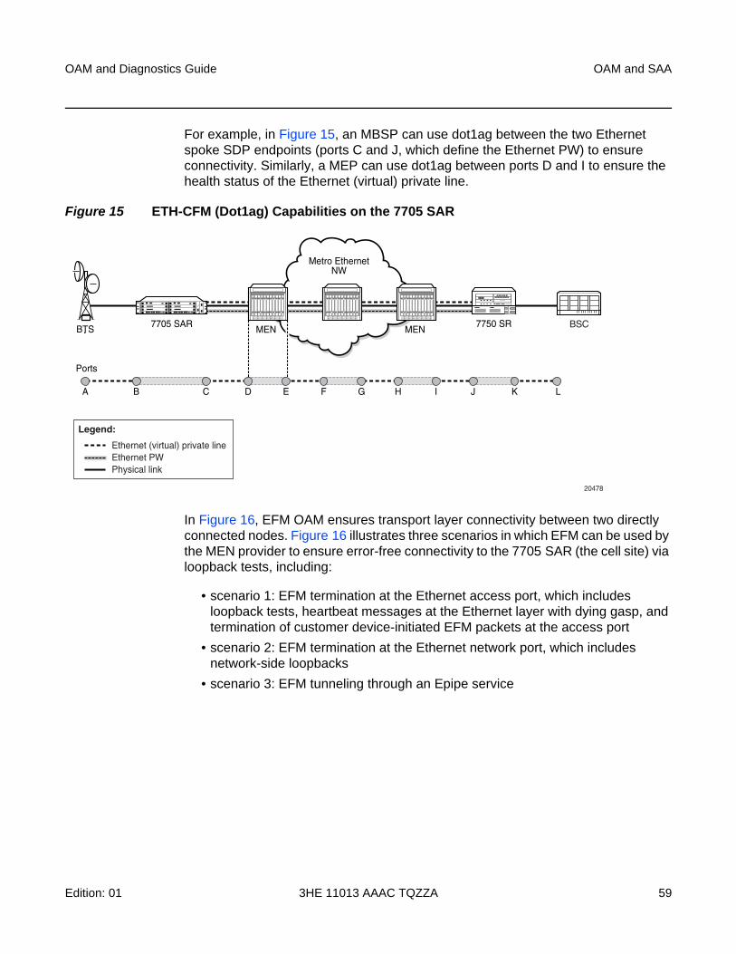
OAM and Diagnostics Guide OAM and SAA
Edition: 01 3HE 11013 AAAC TQZZA 59
For example, in Figure 15, an MBSP can use dot1ag between the two Ethernet spoke SDP endpoints (ports C and J, which define the Ethernet PW) to ensure connectivity. Similarly, a MEP can use dot1ag between ports D and I to ensure the health status of the Ethernet (virtual) private line.
Figure 15 ETH-CFM (Dot1ag) Capabilities on the 7705 SAR
In Figure 16, EFM OAM ensures transport layer connectivity between two directly connected nodes. Figure 16 illustrates three scenarios in which EFM can be used by the MEN provider to ensure error-free connectivity to the 7705 SAR (the cell site) via loopback tests, including:
• scenario 1: EFM termination at the Ethernet access port, which includes loopback tests, heartbeat messages at the Ethernet layer with dying gasp, and termination of customer device-initiated EFM packets at the access port
• scenario 2: EFM termination at the Ethernet network port, which includes network-side loopbacks
• scenario 3: EFM tunneling through an Epipe service
Metro EthernetNW
BTS
20478
7705 SARMEN BSC7750 SR
MEN
A
Ports
B C D E F G H I J K L
Ethernet (virtual) private line
Physical linkEthernet PW
Legend:
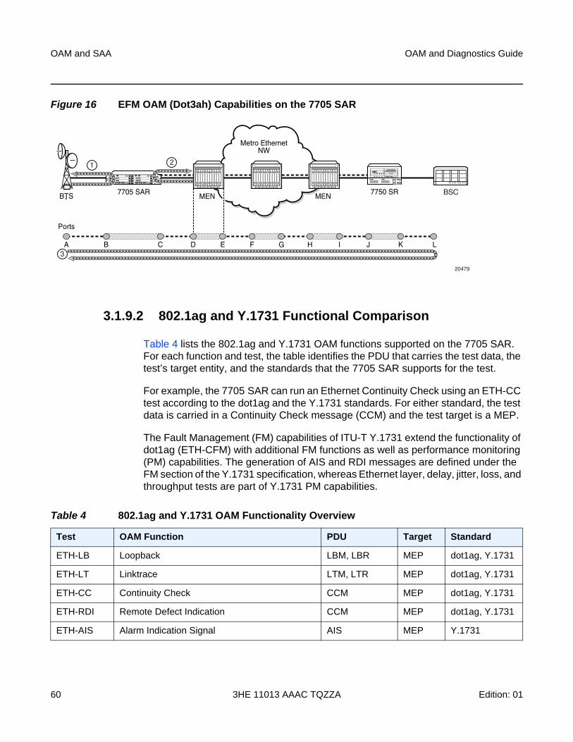
OAM and SAA
60
OAM and Diagnostics Guide
3HE 11013 AAAC TQZZA Edition: 01
Figure 16 EFM OAM (Dot3ah) Capabilities on the 7705 SAR
3.1.9.2 802.1ag and Y.1731 Functional Comparison
Table 4 lists the 802.1ag and Y.1731 OAM functions supported on the 7705 SAR. For each function and test, the table identifies the PDU that carries the test data, the test’s target entity, and the standards that the 7705 SAR supports for the test.
For example, the 7705 SAR can run an Ethernet Continuity Check using an ETH-CC test according to the dot1ag and the Y.1731 standards. For either standard, the test data is carried in a Continuity Check message (CCM) and the test target is a MEP.
The Fault Management (FM) capabilities of ITU-T Y.1731 extend the functionality of dot1ag (ETH-CFM) with additional FM functions as well as performance monitoring (PM) capabilities. The generation of AIS and RDI messages are defined under the FM section of the Y.1731 specification, whereas Ethernet layer, delay, jitter, loss, and throughput tests are part of Y.1731 PM capabilities.
Metro EthernetNW
20479
7705 SARMEN BSC7750 SR
A
Ports
B C D E F G H I J K L
BTS MEN
1
3
2
Table 4 802.1ag and Y.1731 OAM Functionality Overview
Test OAM Function PDU Target Standard
ETH-LB Loopback LBM, LBR MEP dot1ag, Y.1731
ETH-LT Linktrace LTM, LTR MEP dot1ag, Y.1731
ETH-CC Continuity Check CCM MEP dot1ag, Y.1731
ETH-RDI Remote Defect Indication CCM MEP dot1ag, Y.1731
ETH-AIS Alarm Indication Signal AIS MEP Y.1731
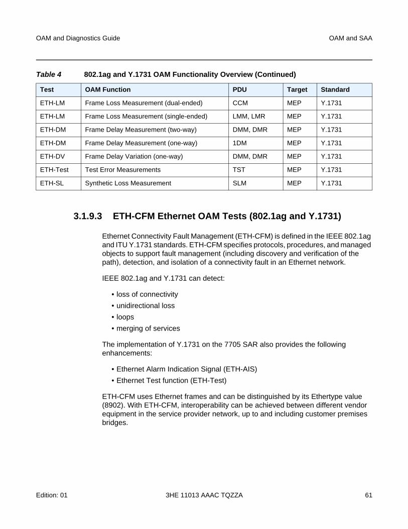
OAM and Diagnostics Guide OAM and SAA
Edition: 01 3HE 11013 AAAC TQZZA 61
3.1.9.3 ETH-CFM Ethernet OAM Tests (802.1ag and Y.1731)
Ethernet Connectivity Fault Management (ETH-CFM) is defined in the IEEE 802.1ag and ITU Y.1731 standards. ETH-CFM specifies protocols, procedures, and managed objects to support fault management (including discovery and verification of the path), detection, and isolation of a connectivity fault in an Ethernet network.
IEEE 802.1ag and Y.1731 can detect:
• loss of connectivity
• unidirectional loss
• loops
• merging of services
The implementation of Y.1731 on the 7705 SAR also provides the following enhancements:
• Ethernet Alarm Indication Signal (ETH-AIS)
• Ethernet Test function (ETH-Test)
ETH-CFM uses Ethernet frames and can be distinguished by its Ethertype value (8902). With ETH-CFM, interoperability can be achieved between different vendor equipment in the service provider network, up to and including customer premises bridges.
ETH-LM Frame Loss Measurement (dual-ended) CCM MEP Y.1731
ETH-LM Frame Loss Measurement (single-ended) LMM, LMR MEP Y.1731
ETH-DM Frame Delay Measurement (two-way) DMM, DMR MEP Y.1731
ETH-DM Frame Delay Measurement (one-way) 1DM MEP Y.1731
ETH-DV Frame Delay Variation (one-way) DMM, DMR MEP Y.1731
ETH-Test Test Error Measurements TST MEP Y.1731
ETH-SL Synthetic Loss Measurement SLM MEP Y.1731
Table 4 802.1ag and Y.1731 OAM Functionality Overview (Continued)
Test OAM Function PDU Target Standard
OAM and SAA
62
OAM and Diagnostics Guide
3HE 11013 AAAC TQZZA Edition: 01
ETH-CFM is configured at the global level and at the Ethernet service level and/or network interface level. The following entities and their configuration levels are listed below:
• global level
− MA and MEG
− MD
− MD level and MEG level
• Ethernet service level
− MEP
• Ethernet network interface level
− facility MEP
For information on configuring ETH-CFM to set up an Ethernet OAM architecture, refer to the 7705 SAR Services Guide, “ETH-CFM (802.1ag and Y.1731)”. Most of the configuration information applies to Ethernet network interfaces as well; for information on ETH-CFM support specific to network interfaces, refer to the 7705 SAR Router Configuration Guide, “ETH-CFM Support”.
3.1.9.3.1 Hold MEP Up On Failure
The hold MEP up on failure function allows MEP operation that is independent of SAP status. In order to report service–level agreement (SLA) metrics, transport providers run Y.1731 performance monitoring tests periodically. At preset times, transport providers initiate various tests to measure and record one or all required SLA components: jitter, delay, loss and throughput. The ability to hold MEP up allows the MEP to be kept in operation even if the SAP is down or non-operational.
The hold MEP up on failure function is only applicable to Ethernet pseudowire services operating between SAPs or between SAPs and SDPs. The SAP connecting the provider equipment to the customer can be configured to hold the MEP in operation when the customer-facing SAP enters any failed state. Only one SAP per Ethernet pseudowire can be configured in this manner. Pseudowire status will indicate a failed SAP in the LDP status message but as long as the pseudowire is in an operationally up state, it supports receiving frames from the network’s far-end side. Counters are also incremented to accurately represent the number of received packets.
ETH-CFM PM measurements, ETH-CFM troubleshooting tools and connectivity, and ETH-CFM CCM processing and fault propagation are not impacted by this feature and continue to function normally.
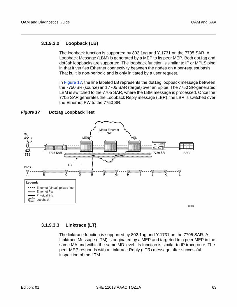
OAM and Diagnostics Guide OAM and SAA
Edition: 01 3HE 11013 AAAC TQZZA 63
3.1.9.3.2 Loopback (LB)
The loopback function is supported by 802.1ag and Y.1731 on the 7705 SAR. A Loopback Message (LBM) is generated by a MEP to its peer MEP. Both dot1ag and dot3ah loopbacks are supported. The loopback function is similar to IP or MPLS ping in that it verifies Ethernet connectivity between the nodes on a per-request basis. That is, it is non-periodic and is only initiated by a user request.
In Figure 17, the line labeled LB represents the dot1ag loopback message between the 7750 SR (source) and 7705 SAR (target) over an Epipe. The 7750 SR-generated LBM is switched to the 7705 SAR, where the LBM message is processed. Once the 7705 SAR generates the Loopback Reply message (LBR), the LBR is switched over the Ethernet PW to the 7750 SR.
Figure 17 Dot1ag Loopback Test
3.1.9.3.3 Linktrace (LT)
The linktrace function is supported by 802.1ag and Y.1731 on the 7705 SAR. A Linktrace Message (LTM) is originated by a MEP and targeted to a peer MEP in the same MA and within the same MD level. Its function is similar to IP traceroute. The peer MEP responds with a Linktrace Reply (LTR) message after successful inspection of the LTM.
Metro EthernetNW
BTS
20480
7705 SAR
A
Ports
B C D E F G H I J K L
LB
7750 SR
MEN MEN
BSC
Ethernet (virtual) private line
Physical linkLoopback
Ethernet PW
Legend:
OAM and SAA
64
OAM and Diagnostics Guide
3HE 11013 AAAC TQZZA Edition: 01
3.1.9.3.4 Throughput Measurement
Throughput measurement is performed by sending frames to the far end at an increasing rate (up to wire speed) and measuring the percentage of frames received back. In general, the rate is dependent on frame size; the larger the frame size, the lower the rate.
The Y.1731 specification recommends the use of unicast ETH-LB and ETH-Test frames to measure throughput.
On the 7705 SAR, LBM processing and LBR generation is enhanced and occurs on the datapath, allowing the node to respond to loopback messages at wire speed and making in-service throughput tests possible. Thus, if the 7705 SAR receives LBMs at up to wire speed, it can generate up to an equal number of LBRs. In order to process LBMs at wire speed, there must be either no TLVs or a single TLV (which is a Data TLV) in the LBM frame. The End TLV field (0) must be present and the frame can be padded with data after the End TLV field in order to increase the size of the frame. The MAC address cannot be a multicast MAC address; it must be the MEP MAC destination address (DA).
Datapath processing of LBMs is supported for the following MEPs:
• dot1ag
− SAP Up MEP
− SAP Down MEP
− spoke-SDP Down MEP
− network interface facility Down MEP
• Y.1731
− SAP Up MEP
− SAP Down MEP
− network interface facility Down MEP
For spoke-SDP Down MEPs, fastpath (datapath) LBM processing requires that both interfaces—the LBM receiver and the LBR transmitter—reside on the same adapter card. For example, if the 7705 SAR must perform a reroute operation and needs to move the next hop interface to another adapter card (that is, LBMs are received on one card and LBRs are transmitted on another), then the fastpath processing of LBMs is terminated and LBM processing continues via the CSM.
OAM and Diagnostics Guide OAM and SAA
Edition: 01 3HE 11013 AAAC TQZZA 65
3.1.9.3.5 Continuity Check (CC)
The continuity check function is supported by 802.1ag and Y.1731 on the 7705 SAR. A Continuity Check Message (CCM) is a multicast frame that is generated by a MEP and sent to its remote MEPs in the same MA. The CCM does not require a reply message. To identify faults, the receiving MEP maintains a MEP database with the MAC addresses of the remote MEPs with which it expects to maintain connectivity checking. The MEP database can be provisioned manually. If there is no CCM from a monitored remote MEP in a preconfigured period, the local MEP raises an alarm.
The following CC capabilities are supported:
• enable and disable CC for a MEP
• automatically put local MEPs into the database when they are created
• manually configure and delete the MEP entries in the CC MEP monitoring database. The only local provisioning required to identify a remote MEP is the remote MEP identifier (using the remote-mepid mep-id command).
• CCM transmit interval: 10ms, 100ms, 1s, 10s, 1m, 10m (default: 10s)
• transmit interval: 10ms, 100ms, 1s, 10s, 1m, 10m (default: 10s)
• CCM declares a fault when it:
− stops hearing from one of the remote MEPs for a period of 3.5 times the CC interval
− hears from a MEP with a lower MD level
− hears from a MEP that is not in the same MA
− hears from a MEP that is in the same MA but is not in the configured MEP list
− hears from a MEP that is in the same MA with the same MEP ID as the receiving MEP
− recognizes that the CC interval of the remote MEP does not match the local configured CC interval
− recognizes that the remote MEP declares a fault
An alarm is raised and a trap is sent if the defect is greater than or equal to the configured low-priority-defect value.
• CC must be enabled in order for RDI information to be carried in the CCM OAMPDU
The optional ccm-tlv-ignore command can be used to ignore the receipt of interface-status and port-status TLVs in the ETH-CCM PDU on a facility MEP. No processing is performed on ignored ETH-CCM TLV values.
OAM and SAA
66
OAM and Diagnostics Guide
3HE 11013 AAAC TQZZA Edition: 01
Any TLV that is ignored is reported as absent to the relevant remote peer, and the values in the TLV do not have any effect. This is the same behavior as if the received ETH-CCM PDU never included these TLVs in the first place. If the TLV is not properly formed, the ETH-CCM PDU will fail the packet parsing process, which will cause it to be discarded and an alarm to be raised.
3.1.9.3.6 ETH-RDI
The Ethernet Remote Defect Indication function (ETH-RDI) is used by a MEP to communicate to its peer MEPs that a defect condition has been encountered. Defect conditions such as signal fail and AIS may result in the transmission of frames with ETH-RDI information. ETH-RDI is used only when ETH-CC transmission is enabled.
ETH-RDI has the following two applications:
• single-ended fault management — the receiving MEP detects an RDI defect condition, which gets correlated with other defect conditions in this MEP. The absence of received ETH-RDI information in a single MEP indicates the absence of defects in the entire MEG.
• contribution to far-end performance monitoring — the transmitting MEP reflects that there was a defect at the far end, which is used as an input to the performance monitoring process
A MEP that is in a defect condition transmits frames with ETH-RDI information. A MEP, upon receiving frames with ETH-RDI information, determines that its peer MEP has encountered a defect condition.
The specific configuration information required by a MEP to support the ETH-RDI function is as follows:
• MEG level — the MEG level at which the MEP exists
• ETH-RDI transmission period — application-dependent and is the same value as the ETH-CC transmission period
• priority — the priority of frames containing ETH-RDI information and is the same value as the ETH-CC priority
The PDU used to carry ETH-RDI information is the CCM.
OAM and Diagnostics Guide OAM and SAA
Edition: 01 3HE 11013 AAAC TQZZA 67
3.1.9.3.7 ETH-AIS
The Ethernet Alarm Indication Signal function (ETH-AIS) is a Y.1731 CFM enhancement used to suppress alarms at the client (sub) layer following detection of defect conditions at the server (sub) layer.
Transmission of frames with ETH-AIS information can be enabled or disabled on a Y.1731 MEP.
Frames with ETH-AIS information can be issued at the client MEG level by a MEP, including a server MEP, upon detecting the following conditions:
• signal failure conditions in the case where ETH-CC is enabled
• AIS condition in the case where ETH-CC is disabled
For a point-to-point Ethernet connection at the client (sub) layer, a client layer MEP can determine that the server (sub) layer entity providing connectivity to its peer MEP has encountered a defect condition upon receiving a frame with ETH-AIS information. Alarm suppression is simplified by the fact that a MEP is expected to suppress only those defect conditions associated with its peer MEP.
Note: When a port or interface experiences a failure, the Up MEP on the port or interface transmits a Port or Interface Status TLV (or both).
• If the hold-mep-up-on-failure command is enabled:
− the Up MEP indicates ETH-RDI
− the remote MEP indicates a DefMACstatus
• If the hold-mep-up-on-failure command is disabled:
− the Up MEP indicates a DefRemoteCCM defect
− the remote MEP indicates both a DefMACstatus and a DefRDICCM defect
Note: ETH-AIS is not supported on network interface facility MEPs.
OAM and SAA
68
OAM and Diagnostics Guide
3HE 11013 AAAC TQZZA Edition: 01
Only a MEP, including a server MEP, is configured to issue frames with ETH-AIS information. Upon detecting a defect condition, the MEP can immediately start transmitting periodic frames with ETH-AIS information at a configured client MEG level. A MEP continues to transmit periodic frames with ETH-AIS information until the defect condition is removed. Upon receiving a frame with ETH-AIS information from its server (sub) layer, a client (sub) layer MEP detects the AIS condition and suppresses alarms associated with all its peer MEPs. Once the AIS condition is cleared, a MEP resumes alarm generation upon detecting defect conditions.
The following specific configuration information is required by a MEP to support ETH-AIS:
• client MEG level — the MEG level at which the most immediate client layer MEPs exist
• ETH-AIS transmission period — the transmission period of frames with ETH-AIS information
• priority — the priority of frames with ETH-AIS information
3.1.9.3.8 ETH-Test
The Ethernet Test (signal) function (ETH-Test) is a Y.1731 CFM enhancement used to perform one-way, on-demand, in-service diagnostics tests, which include verifying frame loss, bit errors, and so on.
When configured to perform such tests, a MEP inserts frames with ETH-Test information such as frame size and transmission patterns.
When an in-service ETH-Test function is performed, data traffic is not disrupted and the frames with ETH-Test information are transmitted.
To support ETH-Test, a Y.1731 MEP requires the following configuration information:
• MEG level — the MEG level at which the MEP exists
• unicast MAC address — the unicast MAC address of the peer MEP for which the ETH-Test is intended
Note: The out-of-service diagnostics test is not supported in the 7705 SAR.
OAM and Diagnostics Guide OAM and SAA
Edition: 01 3HE 11013 AAAC TQZZA 69
• data — an optional element with which to configure data length and contents for the MEP. The contents can be a test pattern and an optional checksum.
Examples of test patterns include all 0s or all 1s. At the transmitting MEP, this configuration information is required for a test signal generator that is associated with the MEP. At the receiving MEP, this configuration is required for a test signal detector that is associated with the MEP.
• priority — the priority of frames with ETH-Test information
A MEP inserts frames with ETH-Test information towards a targeted peer MEP. The receiving MEP detects the frames with ETH-Test information and performs the requested measurements.
3.1.9.4 ITU-T Y.1731 Ethernet Bandwidth Notification (ETH-BN)
The Ethernet Bandwidth Notification (ETH-BN) function, as defined in ITU-T Rec. G.8013/Y.1731, is used by a server MEP to signal changes in link bandwidth to a client MEP.
One of the best applications of this functionality is for point-to-point microwave radios. When a microwave radio uses adaptive modulation, the capacity of the radio can change based on the condition of the microwave link. For example, in adverse weather conditions that cause link degradation, the radio can change its modulation scheme to a more robust one (which will reduce the link bandwidth) in order to continue transmitting. This change in bandwidth is communicated from the server MEP on the radio, using ETH-BNM (Ethernet Bandwidth Notification Message), to the client MEP on the connected router. The router responds to this information by adjusting the rate of traffic being sent to the radio. The server MEP continues to transmit periodic frames with ETH-BN information with the currently available bandwidth. When full bandwidth is restored, the ETH-BNM will start indicating the full bandwidth.
When the 7705 SAR, Release 8.0, is interoperating with 9500 MPR-e radios, ETH-BN functionality is supported with 9500 MPR-e radios in standalone mode. ETH-BN support with MWA mode will be considered in a future release.
The 7705 SAR supports the client side of ETH-BN, receiving and acting on the ETH-BN information sent by the server MEP.
ETH-BN is supported on Ethernet ports on the following adapter cards, modules, and platforms:
• 8-port Gigabit Ethernet Adapter card
• 10-port 1GigE/1-port 10GigE X-Adapter card
OAM and SAA
70
OAM and Diagnostics Guide
3HE 11013 AAAC TQZZA Edition: 01
• Packet Microwave Adapter card
• 6-port Ethernet 10Gbps Adapter card
• 2-port 10GigE (Ethernet) Adapter card (v-port)
• 2-port 10GigE (Ethernet) module (v-port)
• 6-port SAR-M Ethernet module
• all fixed platforms, with the exception of Fast Ethernet ports on the 7705 SAR-A (ports 9 to 12)
The ports can be configured for network, access, or hybrid mode. When ETH-BN is enabled on a port with the egress-rate sub-rate allow-eth-bn-rate-changes command, the egress rate, which was configured as a fixed bandwidth, can be dynamically changed based on the available bandwidth indicated by the ETH-BN server.
The maximum egress rate that the port can be set to is the native port rate (for example, 1 Gb/s), and the minimum egress rate is 1 kb/s. If a rate request is outside that range, including 0, it cannot be implemented, and the egress rate is set as close as possible to the requested rate. The egress rate setting has a ±1% accuracy, as rate conversion to the hardware is necessary. Any request for a change less than 1% is ignored.
To reduce the number of bandwidth changes (each change incurs a small data hit), a hold timer can be configured. The range is 1 to 600 s with a default of 5 s. Any ETH-BN message received before the hold timer expires, after the last bandwidth change, is ignored.
The bandwidth indicated by the ETH-BN server includes the FCS; therefore, the include-fcs option must also be selected in the egress-rate command or the bandwidth will not match the intended rate.
For information on the egress-rate command, refer to the “Ethernet Commands” section in the 7705 SAR Interface Configuration Guide, “Configuration Command Reference” chapter.
3.1.9.4.1 Bandwidth Notification Message (BNM)
The PDU used for ETH-BN information is called the Bandwidth Notification Message (BNM).
The BNM PDU format consists of the following fields:
• MEG level – carries the MEG level of the client MEP (0 to 7); this field can be any value
OAM and Diagnostics Guide OAM and SAA
Edition: 01 3HE 11013 AAAC TQZZA 71
• Version – current version is 0
• OpCode – value for this PDU type is GMN (32)
• Flags – contains one information element:
− period – bits 3 to 1 indicate how often BN messages are transmitted; currently, the only valid values are 100 (1 frame/s), 101 (1 frame/10 s), and 110 (1 frame/min)
• TLV Offset – set to 13
• Sub-OpCode – value for this PDU type is BNM (1)
• Nominal Bandwidth – the nominal full bandwidth of the link, in Mb/s; this information is ignored by the 7705 SAR
• Current Bandwidth – the current bandwidth of the link, in Mb/s
• Port ID – a non-zero unique identifier for the port associated with the ETH-BN information, or zero if not used; this information is ignored by the 7705 SAR
• End TLV – all zeros octet value
Typical behavior for ETH-BN is that if no BNM frames are received within an interval of 3.5 times the BNM transmission period indicated in the last BNM frame received, the MEP signals to the management system that it no longer has any bandwidth information (for example, because the full bandwidth has been restored). For the 7705 SAR implementation, no action is taken if no BNM frame arrives within 3.5 periods.
Upon startup or restart of the system, the configured egress rate is used until a BNM arrives on the port with a new bandwidth request from the ETH-BN server MEP.
Event logs are generated each time the egress bandwidth is changed based on reception of a BNM. If a BNM is received that does not result in a bandwidth change, no event log is generated.
BN messages are transmitted with a source MAC address that cannot be a multicast address or have a value of 0. The destination MAC address can be a Class 1 multicast address (that is, 01-80-C2-00-0x) or the MAC address of the configured port. If these conditions are not satisfied, the message is discarded. The packets are rate-limited to the CSM as are all OAM packets.
BN messages with zero, one, or two VLAN tags are supported.
For LAG bundles, the BNM settings in the primary port are propagated to all the other member links. Each link in the bundle must always have the same value.
OAM and SAA
72
OAM and Diagnostics Guide
3HE 11013 AAAC TQZZA Edition: 01
3.1.9.5 ITU-T Y.1731 Performance Monitoring (PM)
The Y.1731 Performance Monitoring (PM) functions can be used to measure Ethernet frame delay, delay variation, throughput (including throughput at queue-rates), and frame loss. These performance parameters are defined for point-to-point Ethernet connections.
3.1.9.5.1 Delay and Delay Variation Measurements (DM and DV)
The Y.1731 recommendation covers the following performance parameters, which are based on Metro Ethernet Forum (MEF) 10:
• frame delay — specified as one-way or round-trip delay for a frame, where frame delay is defined as the time elapsed since the start of transmission of the first bit of the frame by a source node until the reception of the frame by the destination node or the same source node
• frame delay variation — a measure of the variations in the frame delay between a pair of service frames, where the service frames belong to the same CoS instance on a point-to-point Ethernet connection
The performance parameters listed above are applicable to Ethernet services frames. Services frames are those frames that conform to an agreed-upon level of bandwidth profile conformance and are associated with a particular CoS identifier. Services frames are admitted at the ingress Ethernet flow point of a point-to-point Ethernet connection and should be delivered to the egress Ethernet flow point.
The 7705 SAR supports one-way and two-way Ethernet Delay Measurement (ETH-DM) tests (section 8.2 of the Y.1731 standard), using the CLI commands oam> eth-cfm>one-way-delay-test and oam>eth-cfm>two-way-delay-test. Ethernet Delay Variation (ETH-DV) tests are run concurrently with the one-way and two-way ETH-DM tests.
For ETH-DM, the accuracy of the measurement is in the microseconds range.
3.1.9.5.2 Y.1731 Delay Measurement (DM)
Y.1731 delay measurement implementation ensures the most accurate results under all circumstances. The implementation ensures that there is minimal delay measurement error between packet generation and packet play-out over the Ethernet link.
OAM and Diagnostics Guide OAM and SAA
Edition: 01 3HE 11013 AAAC TQZZA 73
In order to isolate delay measurement results from the effects of any queuing, scheduling, and shaping procedures, timestamping of source one-way and two-way delay measurement (1DM and DMM) frames in the transmit direction occurs when the first byte of the DM frame is put on the wire (that is, once the actual serialization starts). Last-minute timestamping ensures that DM tests truly measure the delay between two SAP or port endpoints, and not the delay imposed by the routers. Using these accurate measurements, a network operator can separate the delay introduced by the routers from the transmission delay introduced by the transmission network, such as a Metro Ethernet network (MEN) or Generic Framing Procedure (GFP) over SONET links.
Timestamping of received 1DM and DMM frames is similar to transmitted source 1DM and DMM frames. When a Y.1731 delay measurement frame is identified internally, it is immediately timestamped to ensure reporting of only the network-induced delay and jitter.
With two-way delay measurement, delay measurement reply (DMR) timestamping occurs at the entry point to the egress datapath. DMR frames are then classified according to their configured dot1p setting and experience any scheduling delays experienced by the queue and scheduling priorities that the frames are associated with. Performing DMR timestamping at the entry point to the egress datapath provides the most accurate end-to-end measurement of delay and jitter, as it takes into account the internal delay of the responding node due to other higher-priority packets.
In summary, one-way delay measurement performs timestamping in the transmit direction only when the frame is about to be sent on the wire and in the receive direction when the frame is received, before any queuing at the far end. This provides true transport network-induced delay and jitter measurements. Two-way delay measurement takes into account the delay introduced by queuing and scheduling of the far-end node for true end-to-end measurements.
3.1.9.5.3 Loss Measurement (LM)
The 7705 SAR supports single-ended and dual-ended Ethernet Loss Measurement (ETH-LM) tests. Dual-ended LM tests are enabled under the config>service> epipe>sap>eth-cfm>mep and config>router>if>eth-cfm>mep contexts. When enabled, dual-ended LM tests run continuously in the background. Single-ended LM tests are run from the oam>eth-cfm context and are considered on-demand tests.

OAM and SAA
74
OAM and Diagnostics Guide
3HE 11013 AAAC TQZZA Edition: 01
Y.1731 loss measurement functionality is implemented to ensure the most accurate results under all circumstances. Each adapter card has a network processor (NP). LM counters are maintained at the NP. The NP is responsible for incrementing and resetting these counters. These counters are accessed by the CSM CPU in order to calculate and display the loss (percentage) to the user.
LM/CCM frames follow the associated QoS path and therefore might inadvertently report loss due to local congestion even before the frame is switched onto the link. In order to reflect the true experience of a particular QoS setting, generated LM/CCM frames follow the egress QoS path. Once generated, these frames are classified in the same manner as the applicable dot1p-to-FC mapping, associated queuing, and scheduling rules. Following the proper path ensures that loss measurements reflect the experience of a given FC all the way through the network, including within the 7705 SAR platform. As is the case for any other frame of the same FC (that is, user or control frame), the LM/CCM frame follows the associated QoS path to reflect the real experience.
For example, newly generated LM/CCM frames that have a higher counter value can be forwarded sooner than LM/CCM frames with a lower counter value that have been generated but are waiting to be serviced (that is, frames with a lower queue, a queue in the out-of-profile state; or a single SAP with multiple FCs). As a result, when under congestion, the LM ratio would increase to reflect local loss if lower-priority frames cannot be serviced in a timely manner.
In addition, congestion, and hence prioritization, can occur anywhere in the transport network, which means that a reordering might take place not only on the ingress point, but anywhere in the network along the entire path.
The loss ratio is calculated based on the aggregate frames being transmitted and received. Thus, in a uncongested network, the loss ratio would be 0%. With congestion, not all frames may be sent out to the network (that is, higher priority traffic, and so on) or any one of the transit nodes or the endpoint node might drop the packet, which would end up with loss.
The above-described behavior for following the QoS path equally applies to both Up and Down MEPs. Loss measurements in both up and down directions for the same MEP can be performed simultaneously.
The counters used for loss measurement in LM and CCM frames are appended as late as possible in the datapath. Appending the counters at the last minute to the LM or CCM frames ensures that a scheduling priority issue or some other queue-delaying event does not delay the OAM frame in a queue. If the counters are updated or generated earlier in the datapath, then the OAM frames could be affected by queuing or scheduling delays, which might cause the frames to be counted as lost frames when the far-end receive timer expires.
OAM and Diagnostics Guide OAM and SAA
Edition: 01 3HE 11013 AAAC TQZZA 75
The following notes apply to Y.1731 LM tests.
• Single-ended and dual-ended LM tests cannot be enabled on a MEP simultaneously. That is, either a single-ended or a dual-ended LM test can be enabled on a given MEP at any given time.
• The behavior and the interaction between single- and dual-ended LM tests are described in the following list. Error conditions, such as correct domain level and valid destination address (DA) MAC, are not covered in the list:
− if dual-ended loss test is disabled:
• CCM frames are transmitted with LM counters set to 0
• CCM frames being received are not processed for LM
• LMM and LMR frames being received are processed
• single-ended tests can be enabled (not blocked by CLI)
− if dual-ended loss test is enabled:
• single-ended tests cannot be enabled (blocked by CLI)
• LMM and LMR frames being received will be dropped
• Multiple MEPs bound to the same Epipe SAP but belonging to different MEG levels can perform LM tests simultaneously.
• CCM must be enabled before a dual-ended LM test can be enabled.
• When a dual-ended LM test is enabled, the user cannot disable CCM. The dual-ended LM test needs to be disabled before the CCM can be disabled.
• For dual-ended LM tests, an alarm is declared when frame losses are greater than an alarm threshold configured for the MEP. The granularity of the alarm threshold (declaring or clearing) is 0.01%. The default threshold is set to 0.25%.
• On a per-SAP or per-network interface basis, there is one set of Rx and Tx Local LM counters and one set of Rx and Tx Remote LM counters. LM counters are not separated on a per-MAC source address (SA) basis. All MEPs, irrespective of their MD or MEG level, share the same set of Rx and Tx LM counters.
• On the CLI, there are interval counters and accumulated counters. The CCM counters are referred to as Local and FarEnd counters and the accumulated counters are referred to as Near-End and Far-End counters.
• The LM counters are incremented when a user data frame reaches a SAP. Since there is only one set of Tx and Rx Local counters per SAP, each user data frame received by all the MEPs configured on that SAP is counted.
• OAM frames with MEP levels matching or lower than the locally configured MEP level are not counted. They are treated and processed as OAM frames. This functionality applies to both received and transmitted OAM frames. CFM OAM frames at higher MEP levels are counted as user data frames.
− For example, assume a SAP with two MEPs configured on it; one MEP at level 5 and the other at level 6.
OAM and SAA
76
OAM and Diagnostics Guide
3HE 11013 AAAC TQZZA Edition: 01
− When a level 6 OAM frame is received, it is extracted to the CSM for processing and is not counted by LM counters. It is treated as an OAM frame.
− The same behavior applies in the transmit direction. In the above example, any level 5 or level 6 OAM frames generated by the local SAR would not be counted by the far-end LM counters.
• For dual-ended LM tests, any received CCMs with all LM counters being 0s (zeros) are treated as invalid. In this case, the 7705 SAR resets the LM counters for the current and previous CCMs to 0s (zeros). Accumulated counters are not reset.
• Except for a valid counter rollover scenario, if the value of any CCM/LMR counter is less than the value of the same counter in the previous CCM/LMR frame, then the accumulated values of all counters are not increased; they are kept at the same values as before the last CCM/LMR frame is processed.
• When the first valid CCM/LMR frame — that is, a frame with at least one non-zero LM counter — is received after a dual-ended loss test is enabled or a single-ended loss test is launched, the accumulated values cannot be calculated. In this case, the counters are resaved as current counters. When the next received CCM/LMR frame with valid LM counts is received, it will trigger the update of accumulation counts.
Accumulated counts always start at 0 for each launch of a single-ended test. However, the accumulation counts do not change nor do they get reset to all 0s when dual-ended loss tests become disabled. For dual-ended loss tests, accumulated counts can be restarted at 0s by removing the existing LM result of a particular MEP with the CLI command clear>eth-cfm>dual-ended-loss-test>mep mep-id domain md-index association ma-index, or the equivalent SNMP command.
3.1.9.6 CFM OAM QoS
It is important that CFM OAM tools use the relevant FC and the associated queue to report traffic performance issues such as delay, jitter, and loss. When user traffic is mapped to one FC/queue and the OAM traffic is mapped to another FC/queue, data reported by the OAM tools might not be a true reflection of the performance metrics that the user traffic is experiencing, due mainly to different queue depths and scheduling priorities.
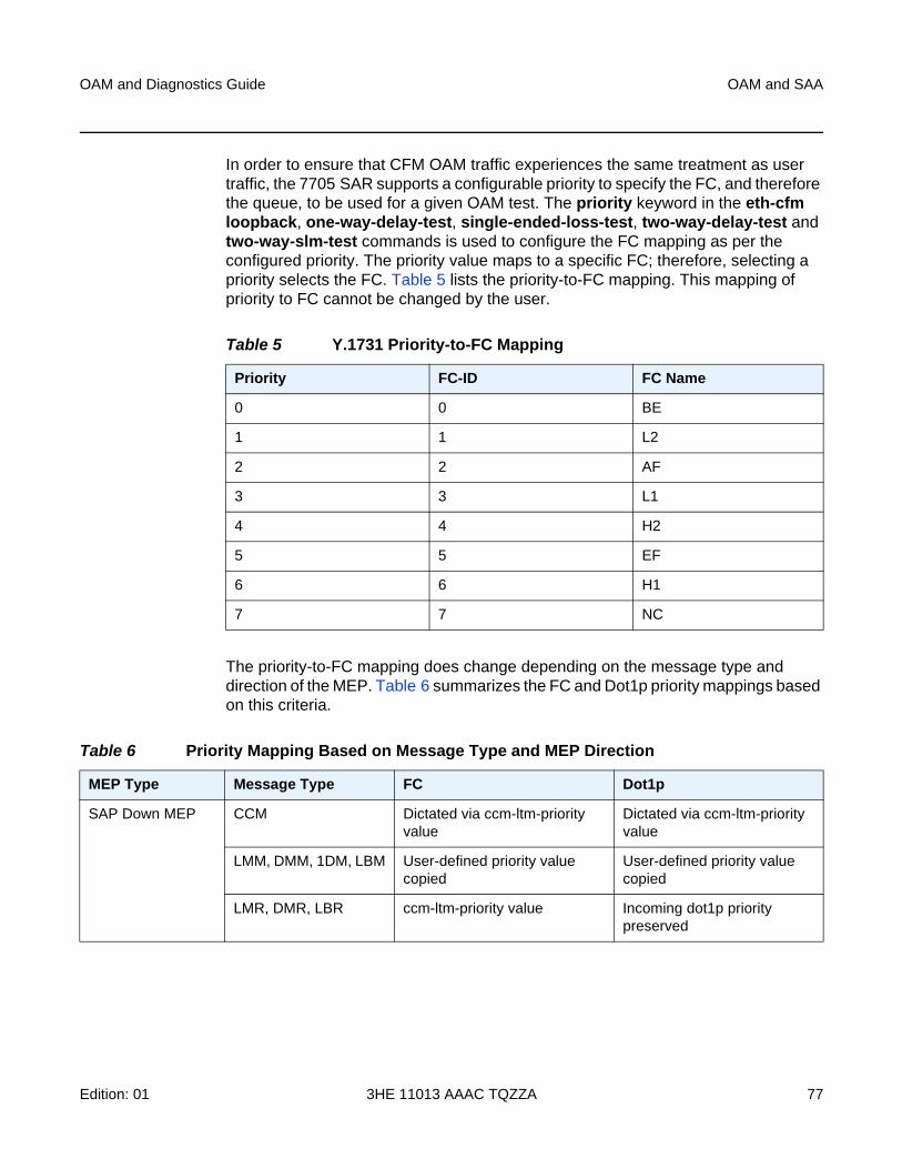
OAM and Diagnostics Guide OAM and SAA
Edition: 01 3HE 11013 AAAC TQZZA 77
In order to ensure that CFM OAM traffic experiences the same treatment as user traffic, the 7705 SAR supports a configurable priority to specify the FC, and therefore the queue, to be used for a given OAM test. The priority keyword in the eth-cfm loopback, one-way-delay-test, single-ended-loss-test, two-way-delay-test and two-way-slm-test commands is used to configure the FC mapping as per the configured priority. The priority value maps to a specific FC; therefore, selecting a priority selects the FC. Table 5 lists the priority-to-FC mapping. This mapping of priority to FC cannot be changed by the user.
The priority-to-FC mapping does change depending on the message type and direction of the MEP. Table 6 summarizes the FC and Dot1p priority mappings based on this criteria.
Table 5 Y.1731 Priority-to-FC Mapping
Priority FC-ID FC Name
0 0 BE
1 1 L2
2 2 AF
3 3 L1
4 4 H2
5 5 EF
6 6 H1
7 7 NC
Table 6 Priority Mapping Based on Message Type and MEP Direction
MEP Type Message Type FC Dot1p
SAP Down MEP CCM Dictated via ccm-ltm-priority value
Dictated via ccm-ltm-priority value
LMM, DMM, 1DM, LBM User-defined priority value copied
User-defined priority value copied
LMR, DMR, LBR ccm-ltm-priority value Incoming dot1p priority preserved
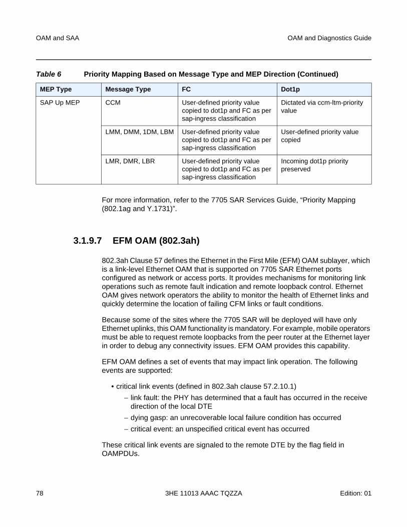
OAM and SAA
78
OAM and Diagnostics Guide
3HE 11013 AAAC TQZZA Edition: 01
For more information, refer to the 7705 SAR Services Guide, “Priority Mapping (802.1ag and Y.1731)”.
3.1.9.7 EFM OAM (802.3ah)
802.3ah Clause 57 defines the Ethernet in the First Mile (EFM) OAM sublayer, which is a link-level Ethernet OAM that is supported on 7705 SAR Ethernet ports configured as network or access ports. It provides mechanisms for monitoring link operations such as remote fault indication and remote loopback control. Ethernet OAM gives network operators the ability to monitor the health of Ethernet links and quickly determine the location of failing CFM links or fault conditions.
Because some of the sites where the 7705 SAR will be deployed will have only Ethernet uplinks, this OAM functionality is mandatory. For example, mobile operators must be able to request remote loopbacks from the peer router at the Ethernet layer in order to debug any connectivity issues. EFM OAM provides this capability.
EFM OAM defines a set of events that may impact link operation. The following events are supported:
• critical link events (defined in 802.3ah clause 57.2.10.1)
− link fault: the PHY has determined that a fault has occurred in the receive direction of the local DTE
− dying gasp: an unrecoverable local failure condition has occurred
− critical event: an unspecified critical event has occurred
These critical link events are signaled to the remote DTE by the flag field in OAMPDUs.
SAP Up MEP CCM User-defined priority value copied to dot1p and FC as per sap-ingress classification
Dictated via ccm-ltm-priority value
LMM, DMM, 1DM, LBM User-defined priority value copied to dot1p and FC as per sap-ingress classification
User-defined priority value copied
LMR, DMR, LBR User-defined priority value copied to dot1p and FC as per sap-ingress classification
Incoming dot1p priority preserved
Table 6 Priority Mapping Based on Message Type and MEP Direction (Continued)
MEP Type Message Type FC Dot1p
OAM and Diagnostics Guide OAM and SAA
Edition: 01 3HE 11013 AAAC TQZZA 79
EFM OAM is supported on network and access Ethernet ports, and is configured at the Ethernet port level. The access ports can be configured to tunnel the OAM traffic originated by the far-end devices.
EFM OAM has the following characteristics.
• All EFM OAM, including loopbacks, operate on point-to-point links only.
• EFM loopbacks are always line loopbacks (line Rx to line Tx).
• When a port is in loopback, all frames (except EFM frames) are discarded. If dynamic signaling and routing is used (dynamic LSPs, OSPF, IS-IS, or BGP routing), all services also go down. If all signaling and routing protocols are static (static routes, LSPs, and service labels), the frames are discarded but services stay up.
The following EFM OAM functions are supported:
• OAM capability discovery
• configurable transmit interval with an Information OAMPDU
• active or passive mode
• OAM loopback
• OAMPDU tunneling and termination (for Epipe service)
• dying gasp at network and access ports
For information on Epipe service, refer to the 7705 SAR Services Guide, “Ethernet VLL (Epipe) Services”.
3.1.9.7.1 Unidirectional OAM Operation
Some physical layer devices support unidirectional OAM operation. When a link is operating in unidirectional OAM mode, the OAM sublayer ensures that only information OAMPDUs with the Link Fault critical link event indication set and no Information TLVs are sent across the link.
3.1.9.7.2 Remote Loopback
EFM OAM provides a link-layer frame loopback mode, which can be controlled remotely.
OAM and SAA
80
OAM and Diagnostics Guide
3HE 11013 AAAC TQZZA Edition: 01
To initiate a remote loopback, the local EFM OAM client enables the OAM remote loopback command to send a loopback control OAMPDU. After receiving the loopback control OAMPDU, the remote OAM client puts the remote port into local loopback mode.
OAMPDUs are slow protocol frames that contain appropriate control and status information used to monitor, test, and troubleshoot OAM-enabled links.
To exit a remote loopback, the local EFM OAM client sends a loopback control OAMPDU by disabling the OAM remote loopback command. After receiving the loopback control OAMPDU, the remote OAM client puts the port back into normal forwarding mode.
When a port is in local loopback mode (the far end requested an Ethernet OAM loopback), any packets received on the port will be looped back, except for EFM OAMPDUs. No data will be transmitted from the node; only data that is received on the node will be sent back out.
When the node is in remote loopback mode, local data from the CSM is transmitted, but any data received on the node is dropped, except for EFM OAMPDUs.
Remote loopbacks should be used with caution; if dynamic signaling and routing protocols are used, all services go down when a remote loopback is initiated. If only static signaling and routing is used, the services stay up. On the 7705 SAR, the Ethernet port can be configured to accept or reject the remote-loopback command.
3.1.9.7.3 802.3ah OAMPDU Tunneling and Termination for Epipe Services
Customers who subscribe to Epipe service might have customer equipment running 802.3ah at both ends. The 7705 SAR can be configured to tunnel EFM OAMPDUs received from a customer device to the other end through the existing network using MPLS or GRE, or to terminate received OAMPDUs at a network or an access Ethernet port.
While tunneling offers the ability to terminate and process the OAM messages at the head-end, termination on the first access port at the cell site can be used to detect immediate failures or can be used to detect port failures in a timelier manner.
The user can choose either tunneling or termination, but not both at the same time.
Note: This feature applies only to port-based Epipe SAPs because 802.3ah runs at port level, not at VLAN level.
OAM and Diagnostics Guide OAM and SAA
Edition: 01 3HE 11013 AAAC TQZZA 81
In Figure 16, scenario 1 shows the termination of received EFM OAMPDUs from a customer device on an access port, while scenario 2 shows the same thing except for a network port. Scenario 3 shows tunneling of EFM OAMPDUs through the associated Ethernet PW. To configure termination (scenario 1), use the config>port>ethernet>efm-oam>no shutdown command.
3.1.9.7.4 Dying Gasp
Dying gasp is used to notify the far end that EFM-OAM is disabled or shut down on the local port. The dying gasp flag is set on the OAMPDUs that are sent to the peer. The far end can then take immediate action and inform upper layers that EFM-OAM is down on the port.
When a dying gasp is received from a peer, the node logs the event and generates an SNMP trap to notify the operator.
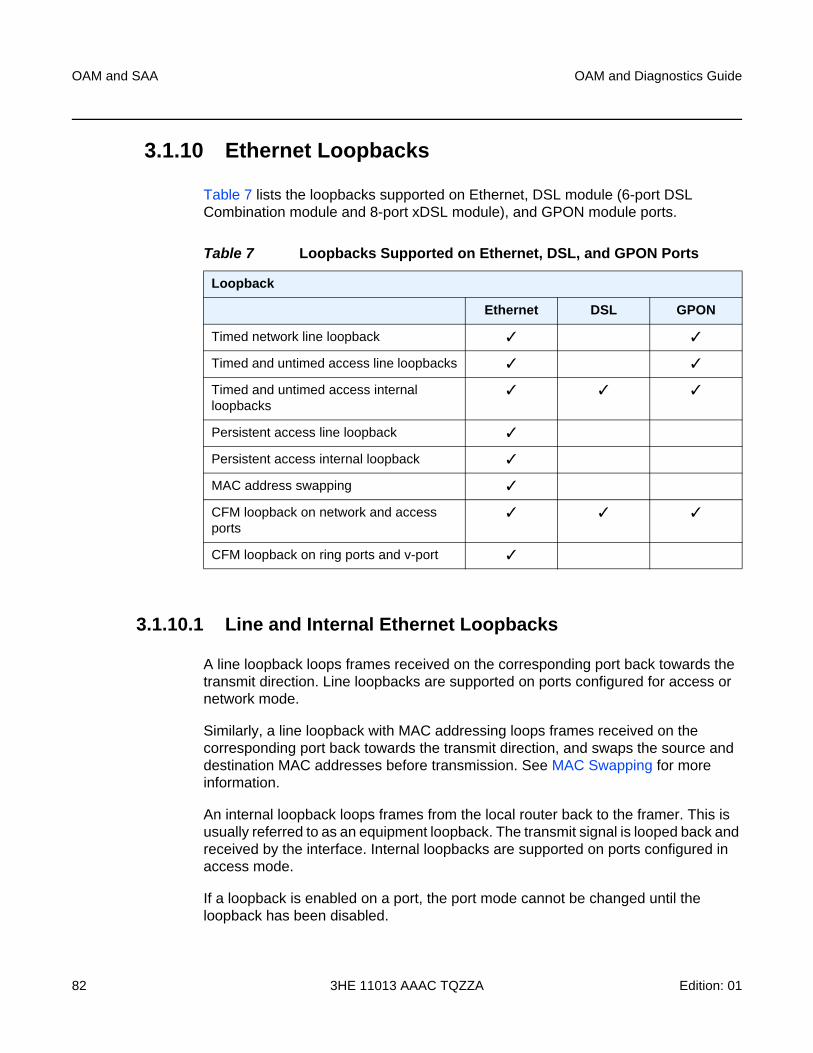
OAM and SAA
82
OAM and Diagnostics Guide
3HE 11013 AAAC TQZZA Edition: 01
3.1.10 Ethernet Loopbacks
Table 7 lists the loopbacks supported on Ethernet, DSL module (6-port DSL Combination module and 8-port xDSL module), and GPON module ports.
3.1.10.1 Line and Internal Ethernet Loopbacks
A line loopback loops frames received on the corresponding port back towards the transmit direction. Line loopbacks are supported on ports configured for access or network mode.
Similarly, a line loopback with MAC addressing loops frames received on the corresponding port back towards the transmit direction, and swaps the source and destination MAC addresses before transmission. See MAC Swapping for more information.
An internal loopback loops frames from the local router back to the framer. This is usually referred to as an equipment loopback. The transmit signal is looped back and received by the interface. Internal loopbacks are supported on ports configured in access mode.
If a loopback is enabled on a port, the port mode cannot be changed until the loopback has been disabled.
Table 7 Loopbacks Supported on Ethernet, DSL, and GPON Ports
Loopback
Ethernet DSL GPON
Timed network line loopback ✓ ✓
Timed and untimed access line loopbacks ✓ ✓
Timed and untimed access internal loopbacks
✓ ✓ ✓
Persistent access line loopback ✓
Persistent access internal loopback ✓
MAC address swapping ✓
CFM loopback on network and access ports
✓ ✓ ✓
CFM loopback on ring ports and v-port ✓
OAM and Diagnostics Guide OAM and SAA
Edition: 01 3HE 11013 AAAC TQZZA 83
A port can support only one loopback at a time. If a loopback exists on a port, it must be disabled or the timer must expire before another loopback can be configured on the same port. EFM-OAM cannot be enabled on a port that has an Ethernet loopback enabled on it. Similarly, an Ethernet loopback cannot be enabled on a port that has EFM-OAM enabled on it.
When an internal loopback is enabled on an Ethernet port, autonegotiation is turned off silently. This is to allow an internal loopback when the operational status of a port is down. Any user modification to autonegotiation on a port configured with an internal Ethernet loopback will not take effect until the loopback is disabled.
The loopback timer can be configured from 30 s to 86400 s. All non-zero timed loopbacks are turned off automatically under the following conditions: an adapter card reset, DSL module reset, GPON module reset, an activity switch, or timer expiry. Line or internal loopback timers can also be configured as a latched loopback by setting the timer to 0 s, or as a persistent loopback with the persistent keyword. Latched and persistent loopbacks are enabled indefinitely until turned off by the user. Latched loopbacks survive adapter card resets and activity switches, but are lost if there is a system restart. Persistent loopbacks survive adapter card resets and activity switches and can survive a system restart if the admin>save or admin>save>detail command was executed prior to the restart. Latched loopbacks (untimed) and persistent loopbacks can be enabled only on Ethernet access ports.
Persistent loopbacks are the only Ethernet loopbacks saved to the database by the admin>save and admin>save>detail commands.
3.1.10.1.1 MAC Swapping
Typically, an Ethernet port loopback only echoes back received frames. That is, the received source and destination MAC addresses are not swapped. However, not all Ethernet equipment supports echo mode, where the original sender of the frame must support receiving its own port MAC address as the destination MAC address.
The MAC swapping feature on the 7705 SAR is an optional feature that swaps the received destination MAC address with the source MAC address when an Ethernet port is in loopback mode. After the swap, the FCS is recalculated to ensure the validity of the Ethernet frame and to ensure that the frame is not dropped by the original sender due to a CRC error.
MAC swapping is not supported on the GPON module, 6-port DSL Combination module, or 8-port xDSL module.
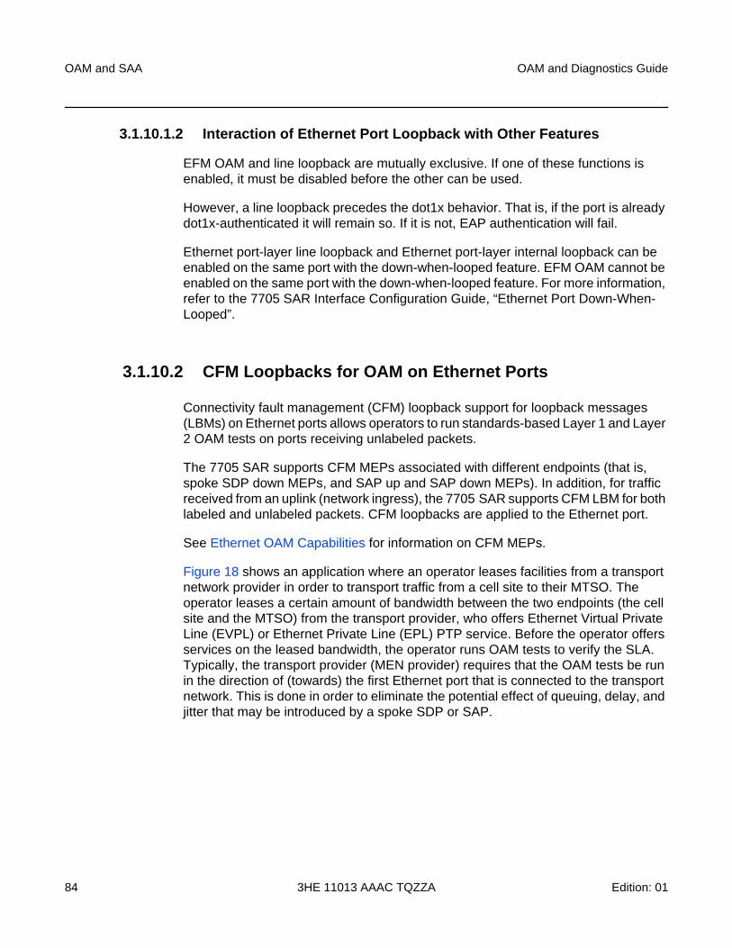
OAM and SAA
84
OAM and Diagnostics Guide
3HE 11013 AAAC TQZZA Edition: 01
3.1.10.1.2 Interaction of Ethernet Port Loopback with Other Features
EFM OAM and line loopback are mutually exclusive. If one of these functions is enabled, it must be disabled before the other can be used.
However, a line loopback precedes the dot1x behavior. That is, if the port is already dot1x-authenticated it will remain so. If it is not, EAP authentication will fail.
Ethernet port-layer line loopback and Ethernet port-layer internal loopback can be enabled on the same port with the down-when-looped feature. EFM OAM cannot be enabled on the same port with the down-when-looped feature. For more information, refer to the 7705 SAR Interface Configuration Guide, “Ethernet Port Down-When-Looped”.
3.1.10.2 CFM Loopbacks for OAM on Ethernet Ports
Connectivity fault management (CFM) loopback support for loopback messages (LBMs) on Ethernet ports allows operators to run standards-based Layer 1 and Layer 2 OAM tests on ports receiving unlabeled packets.
The 7705 SAR supports CFM MEPs associated with different endpoints (that is, spoke SDP down MEPs, and SAP up and SAP down MEPs). In addition, for traffic received from an uplink (network ingress), the 7705 SAR supports CFM LBM for both labeled and unlabeled packets. CFM loopbacks are applied to the Ethernet port.
See Ethernet OAM Capabilities for information on CFM MEPs.
Figure 18 shows an application where an operator leases facilities from a transport network provider in order to transport traffic from a cell site to their MTSO. The operator leases a certain amount of bandwidth between the two endpoints (the cell site and the MTSO) from the transport provider, who offers Ethernet Virtual Private Line (EVPL) or Ethernet Private Line (EPL) PTP service. Before the operator offers services on the leased bandwidth, the operator runs OAM tests to verify the SLA. Typically, the transport provider (MEN provider) requires that the OAM tests be run in the direction of (towards) the first Ethernet port that is connected to the transport network. This is done in order to eliminate the potential effect of queuing, delay, and jitter that may be introduced by a spoke SDP or SAP.
OAM and Diagnostics Guide OAM and SAA
Edition: 01 3HE 11013 AAAC TQZZA 85
Figure 18 CFM Loopback on Ethernet Ports
Figure 18 shows an Ethernet verifier at the MTSO that is directly connected to the transport network (in front of the 7750 SR). Thus, the Ethernet OAM frames are not label- encapsulated. Given that Ethernet verifiers do not support label operations and the transport provider mandates that OAM tests be run between the two hand-off Ethernet ports, the verifier cannot be relocated behind the 7750 SR node at the MTSO. Therefore, CFM loopback frames received are not MPLS-encapsulated, but are simple Ethernet frames where the type is set to CFM (dot1ag or Y.1731).
Metro EthernetNW
21212
DO, LTE
1x
Ethernet EVPL
Cell Site
MTSOEthernet
nxT1
7705 SAR
EthernetVerifier
DSC
2
1
7750 SR
DA=SAR1 SA=Verif LBM
LBM 2SA=SAR DA=VerifDO = Evolution Data OnlyLTE = Long Term EvolutionEVPL = Ethernet Virtual Private LineDSC = Digital Cross-ConnectDA = Destination MAC AddressSA = Source MAC AddressLBM = Loopback Message
Legend:
OAM and SAA
86
OAM and Diagnostics Guide
3HE 11013 AAAC TQZZA Edition: 01
3.1.10.2.1 CFM Loopback Mechanics
The following list contains important facts to consider when working with CFM loopbacks:
• CFM loopbacks can be enabled on a per-port basis, and:
− the port can be in access or network mode
− once enabled on a port, all received LBM frames are processed, regardless of the VLAN and the service that the VLAN or SAP is bound to
− there is no associated MEP creation involved with this feature; therefore, no domain, association, or similar checks are performed on the received frame
− upon finding a destination address MAC match, the LBM frame is sent to the CFM process
• CFM loopback support on a physical ring port on the 2-port 10GigE (Ethernet) Adapter card/module differs from other Ethernet ports. For these ports, cfm-loopback is configured, optionally, using dot1p and match-vlan to create a list of up to 16 VLANs. The null VLAN is always applied. The CFM Loopback Message will be processed if it does not contain a VLAN header, or if it contains a VLAN header with a VLAN ID that matches one in the configured match-vlan list.
• received LBM frames undergo no queuing or scheduling in the ingress direction
• at egress, loopback reply (LBR) frames are stored in their own queue; that is, a separate new queue is added exclusively for LBR frames
• users can configure the way a response frame is treated among other user traffic stored in network queues; the configuration options are high-priority, low-priority, or dot1p, where dot1p applies only to physical ring ports
• for network egress, where profiled scheduling is enabled, the following conditions apply:
− high-priority: either cir = port_speed, which applies to all frames that are scheduled via an in-profile scheduler; or round-robin (RR) for all other (network egress queue) frames that are in-profile
− low-priority: either cir = 0, pir = port_speed, which applies to all frames that are scheduled as out-of-profile, or RR for all other frames that are out-of-profile
• for network egress or access egress, where 4-priority scheduling is enabled:
− high-priority: either cir = port_speed, which applies to all frames that are scheduled via an expedited in-profile scheduler, or RR for all other (network egress queue) frames that reside in expedited queues and are in an in-profile state
OAM and Diagnostics Guide OAM and SAA
Edition: 01 3HE 11013 AAAC TQZZA 87
− low-priority: either cir = 0, pir = port_speed, which applies to all frames that are scheduled via a best effort out-of-profile scheduler, or RR for all other frames that reside in best-effort queues and are in an out-of-profile state
• for the 6-port Ethernet 10Gbps Adapter card, 8-port Gigabit Ethernet Adapter card, the 10-port 1GigE/1-port 10GigE X-Adapter card, and the v-port on the 2-port 10GigE (Ethernet) Adapter card/module, for network egress, where 16-priority scheduling is enabled:
− high-priority: has higher priority than any user frames
− low-priority: has lower priority than any user frames
• for the physical ring ports on the 2-port 10GigE (Ethernet) Adapter card/module, which can only operate as network egress, the priority of the LBR frame is derived from the dot1p setting of the received LBM frame. Based on the assigned ring-type network queue policy, dot1p-to-queue mapping is handled using the same mapping rule that applies to all other user frames.
• the above queue parameters and scheduler mappings are all preconfigured and cannot be altered. The desired QoS treatment is selected by enabling the CFM loopback and specifying high-priority, low-priority, or dot1p.
3.1.11 OAM Propagation to Attachment Circuits
Typically, T1/E1 equipment at a site relies on the physical availability of the T1/E1 ports to determine the uplink capacity (that is, for ATM IMA or MLPPP groups). When a failure in the access link between the 7705 SAR and the associated T1/E1 equipment is detected, notification of the failure is propagated by the PW status signaling using one of two methods — label withdrawal or TLV (see LDP Status Signaling). In addition, the PW failure must also be propagated to the devices attached to the T1/E1 equipment. The propagation method depends on the type of port used by the access circuit (ATM, T1/E1 TDM, or Ethernet) and is described below.
3.1.11.1 ATM Ports
Propagation of ATM PW failures to the ATM port is achieved through the generation of AIS and RDI alarms.
OAM and SAA
88
OAM and Diagnostics Guide
3HE 11013 AAAC TQZZA Edition: 01
3.1.11.2 T1/E1 TDM Ports
If a port on a 16-port T1/E1 ASAP Adapter card, 32-port T1/E1 ASAP Adapter card, or 2-port OC3/STM1 Channelized Adapter card is configured for CESoPSN VLL service, failure of the VLL forces a failure of the associated DS0s (timeslots). Since there can be n × DS0s bound to a CESoPSN VLL service as the attachment circuit, an alarm is propagated to the bound DS0s only. In order to emulate the failure, an “all 1s” or an “all 0s” signal is sent through the DS0s. The bit pattern can be configured to be either all 1s or all 0s. This is sometimes called “trunk conditioning”.
3.1.11.3 Ethernet Ports
For an Ethernet port-based Ethernet VLL, failure of the VLL forces a failure of the local Ethernet port. That is, the local attachment port is taken out of service at the physical layer and the Tx is turned off on the associated Ethernet port.
3.1.11.4 Pseudowire Status Signaling OAM Propagation
See the 7705 SAR Services Guide for more information about frame relay and HDLC PW status signaling and OAM propagation.
3.1.12 LDP Status Signaling
The failure of a local circuit needs to be propagated to the far-end PE, which then propagates the failure to its attached circuits. The 7705 SAR can propagate failures over the PW using one of the following methods:
• LDP status via label withdrawal
• LDP status via TLV
3.1.12.1 LDP Status via Label Withdrawal
Label withdrawal is negotiated during the PW status negotiation phase and needs to be supported by both the near-end and the far-end points. If the far end does not support label withdrawal, the 7705 SAR still withdraws the label in case the local attachment circuit is removed or shut down.
OAM and Diagnostics Guide OAM and SAA
Edition: 01 3HE 11013 AAAC TQZZA 89
Label withdrawal occurs only when the attachment circuit is administratively shut down or deleted. If there is a failure of the attached circuit, the label withdrawal message is not generated.
When the local circuit is re-enabled after shutdown, the VLL must be re-established, which causes some delays and signaling overhead.
3.1.12.2 LDP Status via TLV
Signaling PW status via TLV is supported as per RFC 4447. Signaling PW status via TLV is advertised during the PW capabilities negotiation phase. It is more efficient and is preferred over the label withdrawal method.
For cell mode ATM PWs, when an AIS message is received from the local attachment circuit, the AIS message is propagated to the far-end PE unaltered and PW status TLV is not initiated.
3.1.13 IP Multicast Debugging Tools
This section describes multicast debugging tools for the 7705 SAR.
The debugging tools for multicast consist of three elements, which are accessed from the CLI <global> level:
• Mtrace
• Mstat
• Mrinfo
3.1.13.1 Mtrace
Assessing problems in the distribution of IP multicast traffic can be difficult. The multicast traceroute (mtrace) feature uses a tracing feature implemented in multicast routers that is accessed via an extension to the IGMP protocol. The mtrace feature is used to print the path from the source to a receiver; it does this by passing a trace query hop-by-hop along the reverse path from the receiver to the source. At each hop, information such as the hop address, routing error conditions, and packet statistics are gathered and returned to the requester.
OAM and SAA
90
OAM and Diagnostics Guide
3HE 11013 AAAC TQZZA Edition: 01
Data added by each hop includes:
• query arrival time
• incoming interface
• outgoing interface
• previous hop router address
• input packet count
• output packet count
• total packets for this source/group
• routing protocol
• TTL threshold
• forwarding/error code
The information enables the network administrator to determine:
• the flow of the multicast stream
• where multicast flows stop
When the trace response packet reaches the first-hop router (the router that is directly connected to the source’s network interface), that router sends the completed response to the response destination (receiver) address specified in the trace query.
If a multicast router along the path does not implement the mtrace feature or if there is an outage, then no response is returned. To solve this problem, the trace query includes a maximum hop count field to limit the number of hops traced before the response is returned. This allows a partial path to be traced.
The reports inserted by each router contain not only the address of the hop, but also the TTL required to forward the packets and flags to indicate routing errors, plus counts of the total number of packets on the incoming and outgoing interfaces and those forwarded for the specified group. Examining the differences in these counts for two separate traces and comparing the output packet counts from one hop with the input packet counts of the next hop allows the calculation of packet rate and packet loss statistics for each hop to isolate congestion problems.
OAM and Diagnostics Guide OAM and SAA
Edition: 01 3HE 11013 AAAC TQZZA 91
3.1.13.1.1 Finding the Last-Hop Router
The trace query must be sent to the multicast router that is the last hop on the path from the source to the receiver. If the receiver is on the local subnet (as determined by the subnet mask), then the default method is to send the trace query to all-routers.mcast.net (224.0.0.2) with a TTL of 1. Otherwise, the trace query is sent to the group address since the last-hop router will be a member of that group if the receiver is. Therefore, it is necessary to specify a group that the intended receiver has joined. This multicast query is sent with a default TTL of 64, which may not be sufficient for all cases.
When tracing from a multihomed host or router, the default receiver address may not be the desired interface for the path from the source. In that case, the desired interface should be specified explicitly as the receiver.
3.1.13.1.2 Directing the Response
By default, mtrace first attempts to trace the full reverse path, unless the number of hops to trace is explicitly set with the hop option. If there is no response within a 3-s timeout interval, a “*” is displayed and the probing switches to hop-by-hop mode. Trace queries are issued starting with a maximum hop count of one and increasing by one until the full path is traced or no response is received. At each hop, multiple probes are sent. The first attempt is made with the unicast address of the host running mtrace as the destination for the response. Since the unicast route may be blocked, the remainder of attempts request that the response be sent to mtrace.mcast.net (224.0.1.32) with the TTL set to 32 more than what is needed to pass the thresholds seen so far along the path to the receiver. For the last attempts, the TTL is increased by another 32.
Alternatively, the TTL may be set explicitly with the TTL option.
For each attempt, if no response is received within the timeout, a “*” is displayed. After the specified number of attempts have failed, mtrace will try to query the next-hop router with a DVMRP_ASK_NEIGHBORS2 request (as used by the mrinfo feature) to determine the router type.
The output of mtrace is a short listing of the hops in the order they are queried, that is, in the reverse of the order from the source to the receiver. For each hop, a line is displayed showing:
• the hop number (counted negatively to indicate that this is the reverse path)
• the multicast routing protocol
• the threshold required to forward data (to the previous hop in the listing as indicated by the up-arrow character)
OAM and SAA
92
OAM and Diagnostics Guide
3HE 11013 AAAC TQZZA Edition: 01
• the cumulative delay for the query to reach that hop (valid only if the clocks are synchronized)
The response ends with a line showing the round-trip time which measures the interval from when the query is issued until the response is received, both derived from the local system clock.
Mtrace/mstat packets use special IGMP packets with IGMP type codes of 0x1E and 0x1F.
3.1.13.2 Mstat
The mstat feature adds the capability to show the multicast path in a limited graphic display and indicates drops, duplicates, TTLs, and delays at each node. This information is useful to the network operator because it identifies nodes with high drop and duplicate counts. Duplicate counts are shown as negative drops.
The output of mstat provides a limited pictorial view of the path in the forward direction with data flow indicated by arrows pointing downward and the query path indicated by arrows pointing upward. For each hop, both the entry and exit addresses of the router are shown if different, along with the initial TTL required on the packet in order to be forwarded at this hop and the propagation delay across the hop assuming that the routers at both ends have synchronized clocks. The output consists of two columns, one for the overall multicast packet rate that does not contain lost/sent packets and the other for the (S,G)-specific case. The (S,G) statistics also do not contain lost/sent packets.
3.1.13.3 Mrinfo
The mrinfo feature is a simple mechanism to display the configuration information from the target multicast router. The type of information displayed includes the multicast capabilities of the router, code version, metrics, TTL thresholds, protocols, and status. This information can be used by network operators, for example, to verify if bidirectional adjacencies exist. Once the specified multicast router responds, the configuration is displayed.
OAM and Diagnostics Guide OAM and SAA
Edition: 01 3HE 11013 AAAC TQZZA 93
3.2 Service Assurance Agent Overview
Broadband service delivery technologies have enabled the introduction of broadband service termination applications such as Voice over IP (VoIP), TV service delivery, and video and high-speed Internet services. These new applications force carriers to produce services where the health and quality of Service Level Agreement (SLA) commitments are verifiable, both to the customer and internally (within the carrier).
SAA is a feature that monitors network operations using statistics for parameters such as latency, jitter, response time, and packet loss. The information can be used to troubleshoot network problems and help in problem prevention and network topology planning. The 7705 SAR also supports the following SAA Ethernet CFM tests: loopback, linktrace, two-way delay measurement, and two-way SLM.
The results are saved in SNMP tables that are queried by either the CLI or a management system. Threshold monitors allow for both rising and falling threshold events to alert the provider if SLA performance statistics deviate from the required parameters. SAA CFM tests can be saved to accounting files that can be accessed by the network management system.
SAA allows two-way timing for several applications. This provides carriers and their customers with data to verify that the SLA agreements are being properly enforced. For SAA ICMP ping, one-way timestamping can be enabled at the system level for all outbound SAA ICMP ping packets.
3.2.1 Traceroute Implementation
For various applications, such as LSP traceroute, packets must pass through the network processor while on their way to the control CPU. When the packets exit the control CPU in the egress direction, the network processor inserts a timestamp inside each packet. Only packets processed by the control CPU will receive a timestamp.
When interpreting these timestamps, care must be taken because some nodes are not capable of providing timestamps, as such timestamps must be associated with the same IP address that is being returned to the originator to indicate which hop is being measured.
OAM and SAA
94
OAM and Diagnostics Guide
3HE 11013 AAAC TQZZA Edition: 01
3.2.2 SAA Jitter
Mobile operators require millisecond-level granularity when it comes to delay and jitter measurements. This is especially true for synchronization-over-packet based applications.
Two-way jitter tests measure the jitter in each direction separately. The 7705 SAR provides two-way jitter tests with millisecond granularity for all network deployment applications.
3.2.3 SAA Ethernet CFM Test Support
CFM loopback, linktrace, and two-way delay measurement tests (ETH-DM) can be initiated using SAA. Additional timestamping is required for loopback and linktrace tests. An organization-specific TLV is used on both sender and receiver nodes to carry the timestamp information. Currently, timestamps are only applied by the sender node. This means that any time measurements resulting from the loopback and linktrace tests include the packet processing time used by the remote node. Because ETH-DM uses a four timestamp approach to remove the remote processing time, it should be used for accurate delay measurements.
The SAA versions of the CFM loopback, linktrace, and ETH-DM tests support send-count, interval, timeout, and FC. The summary of the test results are stored in an SAA accounting file.
The 7705 SAR now supports SAA-triggered ETH-DM tests for both Y.1731 and 802.1ag SAP MEPs. In previous releases, these tests were only supported for Y.1731 MEPs. The tests are supported on SAP Up and SAP Down Y.1731 and 802.1ag MEPs.
3.2.3.1 Writing SAA Ethernet CFM Test Results to Accounting Files
When each SAA CFM test is completed, the 7705 SAR collects the results in an accounting file that can be accessed by the network management system. In order to write the SAA test results to an accounting file in a compressed XML format, the results must be collected and entered in the appropriate MIB table, and a record must be generated in the appropriate accounting file.
Refer to the 7705 SAR System Management Guide, “Configuring an Accounting Policy” section, for information about creating accounting files and writing to them.

OAM and Diagnostics Guide OAM and SAA
Edition: 01 3HE 11013 AAAC TQZZA 95
Once an accounting file has been created, accounting information can be specified and collected under the config>log>acct-policy>to file log-file-id context.
OAM and SAA
96
OAM and Diagnostics Guide
3HE 11013 AAAC TQZZA Edition: 01
3.3 Configuring SAA Test Parameters
Use the following CLI syntax to create an SAA test and set test parameters:
CLI Syntax: config# saaconfig>saa# test pingconfig>saa>test$ typeconfig>saa>test>type$ icmp-ping 10.10.221.131 count 50 fc “nc” profile out
config>saa>test>type$ exitconfig>saa>test# no shutdownconfig>saa>test# exitconfig>saa# exit
The following example displays the SAA test configuration output:
A:ALU-48>config>saa----------------------------------------------
test "ping"type
icmp-ping 10.10.221.131 count 50 fc “nc” profile outexitno shutdown
exit----------------------------------------------
The following example displays the result after running the test:
A:ALU-48>config>saa# show saa ping===============================================================================SAA Test Information===============================================================================Test name : pingOwner name : TiMOS CLIDescription : N/AAccounting policy : NoneAdministrative status : EnabledTest type : icmp-ping 10.10.221.131 count 50 fc "nc"
profile outTrap generation : NoneTest runs since last clear : 1Number of failed test runs : 0Last test result : Success-------------------------------------------------------------------------------ThresholdType Direction Threshold Value Last Event Run #-------------------------------------------------------------------------------Jitter-in Rising None None Never None
Falling None None Never NoneJitter-out Rising None None Never None
Falling None None Never NoneJitter-rt Rising None None Never None
Falling None None Never None
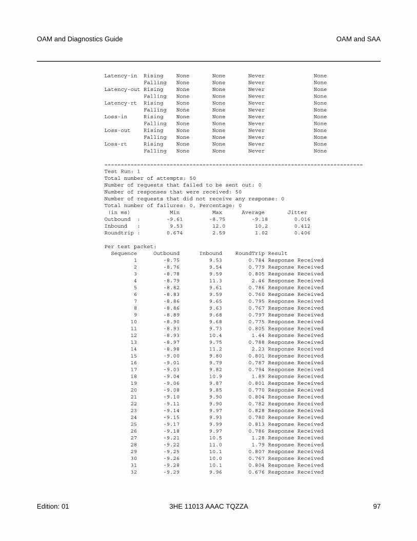
OAM and Diagnostics Guide OAM and SAA
Edition: 01 3HE 11013 AAAC TQZZA 97
Latency-in Rising None None Never NoneFalling None None Never None
Latency-out Rising None None Never NoneFalling None None Never None
Latency-rt Rising None None Never NoneFalling None None Never None
Loss-in Rising None None Never NoneFalling None None Never None
Loss-out Rising None None Never NoneFalling None None Never None
Loss-rt Rising None None Never NoneFalling None None Never None
===============================================================================Test Run: 1Total number of attempts: 50Number of requests that failed to be sent out: 0Number of responses that were received: 50Number of requests that did not receive any response: 0Total number of failures: 0, Percentage: 0(in ms) Min Max Average Jitter
Outbound : -9.61 -8.75 -9.18 0.016Inbound : 9.53 12.0 10.2 0.412Roundtrip : 0.674 2.59 1.02 0.406
Per test packet:Sequence Outbound Inbound RoundTrip Result
1 -8.75 9.53 0.784 Response Received2 -8.76 9.54 0.779 Response Received3 -8.78 9.59 0.805 Response Received4 -8.79 11.3 2.46 Response Received5 -8.82 9.61 0.786 Response Received6 -8.83 9.59 0.760 Response Received7 -8.86 9.65 0.795 Response Received8 -8.86 9.63 0.767 Response Received9 -8.89 9.68 0.797 Response Received
10 -8.90 9.68 0.775 Response Received11 -8.93 9.73 0.805 Response Received12 -8.93 10.4 1.44 Response Received13 -8.97 9.75 0.788 Response Received14 -8.98 11.2 2.23 Response Received15 -9.00 9.80 0.801 Response Received16 -9.01 9.79 0.787 Response Received17 -9.03 9.82 0.794 Response Received18 -9.04 10.9 1.89 Response Received19 -9.06 9.87 0.801 Response Received20 -9.08 9.85 0.770 Response Received21 -9.10 9.90 0.804 Response Received22 -9.11 9.90 0.782 Response Received23 -9.14 9.97 0.828 Response Received24 -9.15 9.93 0.780 Response Received25 -9.17 9.99 0.813 Response Received26 -9.18 9.97 0.786 Response Received27 -9.21 10.5 1.28 Response Received28 -9.22 11.0 1.79 Response Received29 -9.25 10.1 0.807 Response Received30 -9.26 10.0 0.767 Response Received31 -9.28 10.1 0.804 Response Received32 -9.29 9.96 0.676 Response Received
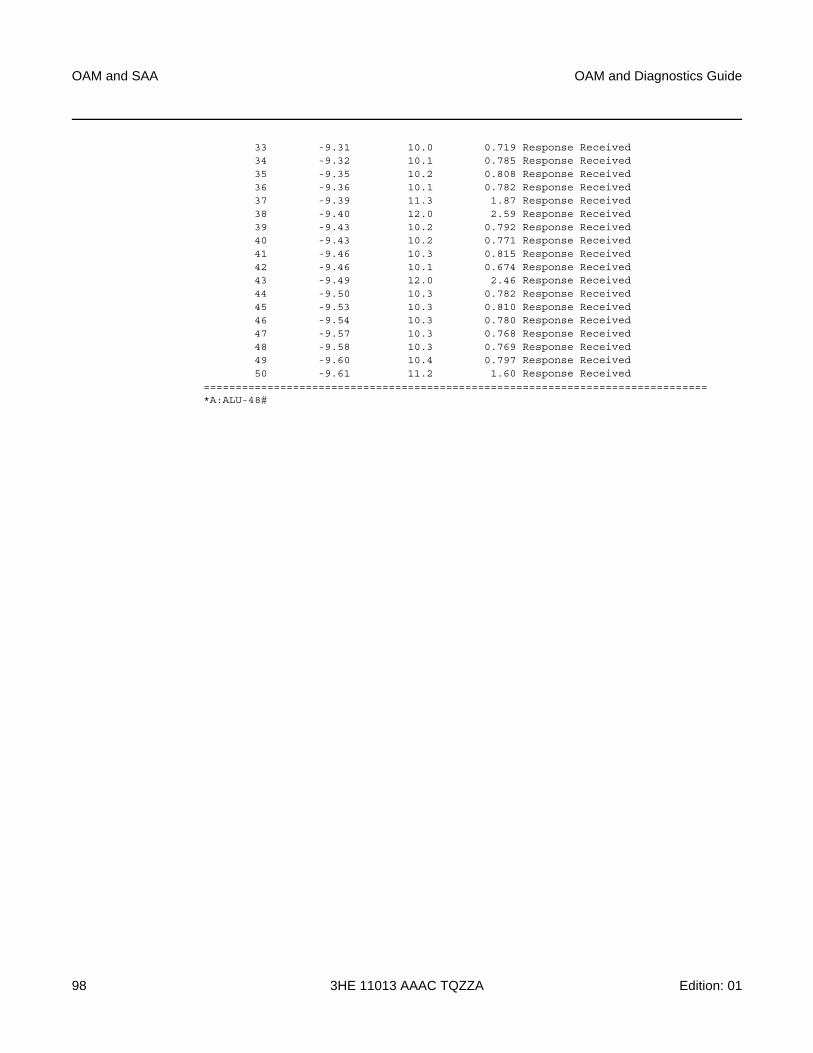
OAM and SAA
98
OAM and Diagnostics Guide
3HE 11013 AAAC TQZZA Edition: 01
33 -9.31 10.0 0.719 Response Received34 -9.32 10.1 0.785 Response Received35 -9.35 10.2 0.808 Response Received36 -9.36 10.1 0.782 Response Received37 -9.39 11.3 1.87 Response Received38 -9.40 12.0 2.59 Response Received39 -9.43 10.2 0.792 Response Received40 -9.43 10.2 0.771 Response Received41 -9.46 10.3 0.815 Response Received42 -9.46 10.1 0.674 Response Received43 -9.49 12.0 2.46 Response Received44 -9.50 10.3 0.782 Response Received45 -9.53 10.3 0.810 Response Received46 -9.54 10.3 0.780 Response Received47 -9.57 10.3 0.768 Response Received48 -9.58 10.3 0.769 Response Received49 -9.60 10.4 0.797 Response Received50 -9.61 11.2 1.60 Response Received
===============================================================================*A:ALU-48#
OAM and Diagnostics Guide OAM and SAA
Edition: 01 3HE 11013 AAAC TQZZA 99
3.4 Synthetic Loss Measurement (SLM)
SLM is a single-ended test that can be run on demand or proactively to determine in-loss, out-loss, and unacknowledged packets. The test uses a small amount of synthetic test traffic as a substitute for customer traffic. SLM is used between peer MEPs in point-to-point configurations. Only remote peer MEPs within the association and matching the unicast destination will respond to the SLM packet. SLM uses an optional TLV with a timestamp on the near-end and far-end MEPs for the combined loss and delay measurement.
Various sequence numbers and counters are used to determine loss in each direction. In order to properly use the information that is gathered, the following terms are defined:
• count — number of probes that are sent if the last frame is not lost. If the last frame is lost, the count plus the number of unacknowledged packets equals the number of probes sent.
• out-loss (far end) — packets lost on the way to the remote node from the test initiator
• in-loss (near end) — packets lost on the way back from the remote node to the test initiator
• unacknowledged — number of packets not responded to by the end of the test
An SLM test packet can be generated using the CLI or SNMP for an on-demand test and SAA for a proactive test.The on-demand test provides per-probe-specific loss indicators or individual probe information stored in the MIB. The test does not store data for later processing. An SAA scheduled or continuous test summarizes the per-probe data but does not maintain per-probe information, and any unacknowledged packets are recorded as in-loss packets.
SLM packets originate and terminate on the CSM card. The probe count for SLM has a configurable range of 1 to 100 with probe spacing between 1 s and 10 s. A single test therefore can be up to 1000 s in length. A node may only initiate and maintain a single active on-demand test at any given time. The results table maintains a maximum of one storage entry per remote MEP. Subsequent tests on the same peer overwrite the results for that peer. For this reason, operators should run the on-demand test and check the results before starting another test.
OAM and SAA
100
OAM and Diagnostics Guide
3HE 11013 AAAC TQZZA Edition: 01
Proactive measurement functions are linked to SAA and provide scheduling, storage, and summarization capabilities. Scheduling can be continuous or periodic. Proactive measurement also allows for the interpretation and representation of data that may enhance the specification. As an example, an optional TLV allows for the measurement of both loss and delay/ jitter with a single test. The optional TLV is ignored by equipment that does not support it. In mixed-vendor environments, loss measurement is tracked but delay and jitter only report round-trip times.
The round-trip times in mixed-vendor environments include the remote node’s processing time because only two timestamps are included in the packet. In an environment where both nodes support the optional TLV to include timestamps, unidirectional and round-trip times are reported. Since all four timestamps are included in the packet, the round-trip time in this case does not include remote node processing time.
The ETH-SL packet format contains a test-id that is internally generated and not configurable. The display summary for the on-demand test shows the test-id. A remote node processing the SLM frames could receive overlapping test-ids due to multiple MEPs measuring the loss at the same remote MEP. For this reason, the uniqueness of the test is based on the remote MEP-ID, test-id, and source MAC address of the packet.
All Ethernet adapter cards and ports in access mode support SLM Down and Up MEPs, and all Ethernet adapter cards and ports in network mode that support spoke SDPs support SLM Down MEPs. SLM Down MEPs are also supported on Ethernet network interfaces. There is no coordination between various fault conditions that could impact loss measurement. This is also true for conditions where MEPs are placed in a shutdown state as a result of linkage to a redundancy scheme such as MC-LAG.
It is possible to have a valid configuration where multiple MEPs on the same remote node have the same MAC address. If this is the case, the first responder is used to measure packet loss. The second responder is dropped.
A configurable inactivity timer determines the length of time that an on-demand test is valid. The test is active as long as packets are received within the timeframe set by the inactivity timer, as defined by the test-id, remote MEP ID, and source MAC address. If there is a gap between the packets that exceeds the inactivity timer value, the responding node responds with a sequence number of 1. For the remote MEP, the previous test has expired and any new probes are now part of a new test. The inactivity timer default is 100 s with a range of 10 to 100 s.
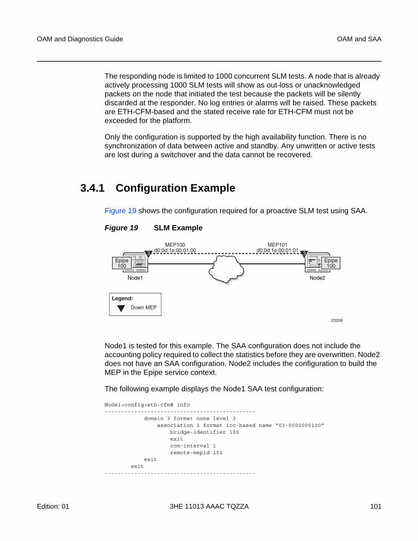
OAM and Diagnostics Guide OAM and SAA
Edition: 01 3HE 11013 AAAC TQZZA 101
The responding node is limited to 1000 concurrent SLM tests. A node that is already actively processing 1000 SLM tests will show as out-loss or unacknowledged packets on the node that initiated the test because the packets will be silently discarded at the responder. No log entries or alarms will be raised. These packets are ETH-CFM-based and the stated receive rate for ETH-CFM must not be exceeded for the platform.
Only the configuration is supported by the high availability function. There is no synchronization of data between active and standby. Any unwritten or active tests are lost during a switchover and the data cannot be recovered.
3.4.1 Configuration Example
Figure 19 shows the configuration required for a proactive SLM test using SAA.
Figure 19 SLM Example
Node1 is tested for this example. The SAA configuration does not include the accounting policy required to collect the statistics before they are overwritten. Node2 does not have an SAA configuration. Node2 includes the configuration to build the MEP in the Epipe service context.
The following example displays the Node1 SAA test configuration:
Node1>config>eth-cfm# info----------------------------------------------
domain 3 format none level 3association 1 format icc-based name “03-0000000100”
bridge-identifier 100exitccm-interval 1remote-mepid 101
exitexit
----------------------------------------------
Node1
Epipe100
3
Node2
Epipe100
3
MEP100d0:0d:1e:00:01:00
MEP101d0:0d:1e:00:01:01
Down MEP
Legend:
23208
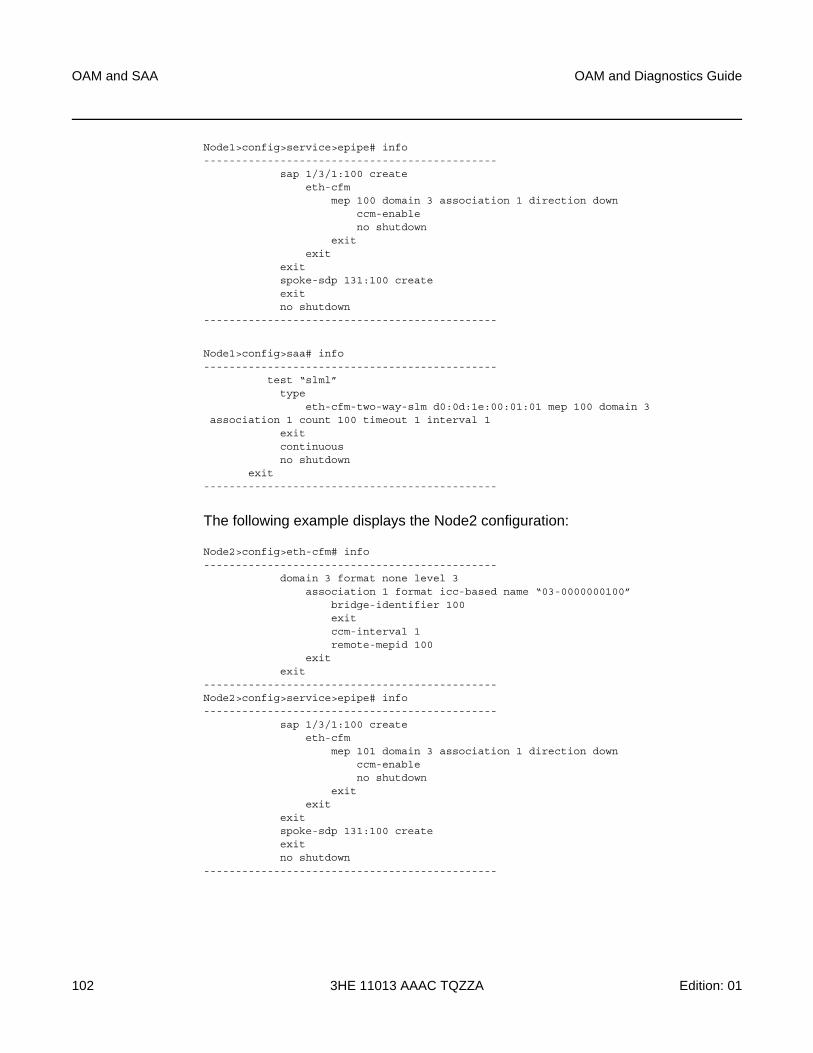
OAM and SAA
102
OAM and Diagnostics Guide
3HE 11013 AAAC TQZZA Edition: 01
Node1>config>service>epipe# info----------------------------------------------
sap 1/3/1:100 createeth-cfm
mep 100 domain 3 association 1 direction downccm-enableno shutdown
exitexit
exitspoke-sdp 131:100 createexitno shutdown
----------------------------------------------
Node1>config>saa# info----------------------------------------------
test “slml”type
eth-cfm-two-way-slm d0:0d:1e:00:01:01 mep 100 domain 3association 1 count 100 timeout 1 interval 1
exitcontinuousno shutdown
exit----------------------------------------------
The following example displays the Node2 configuration:
Node2>config>eth-cfm# info----------------------------------------------
domain 3 format none level 3association 1 format icc-based name “03-0000000100”
bridge-identifier 100exitccm-interval 1remote-mepid 100
exitexit
----------------------------------------------Node2>config>service>epipe# info----------------------------------------------
sap 1/3/1:100 createeth-cfm
mep 101 domain 3 association 1 direction downccm-enableno shutdown
exitexit
exitspoke-sdp 131:100 createexitno shutdown
----------------------------------------------
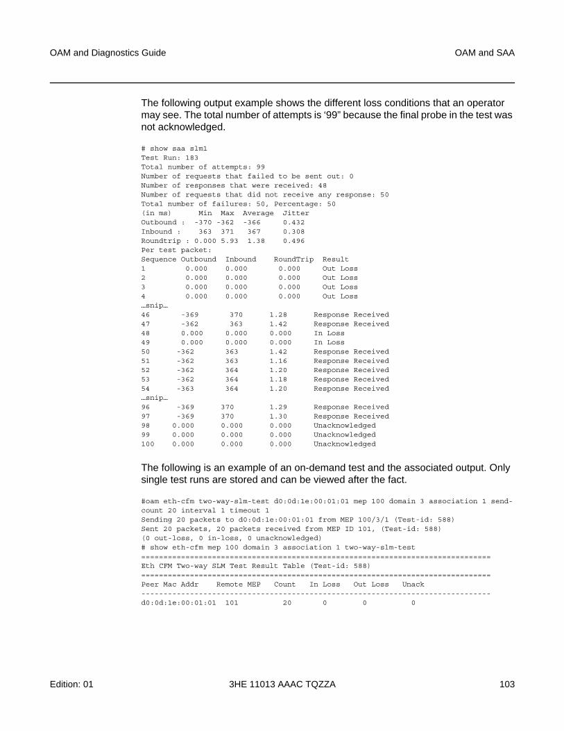
OAM and Diagnostics Guide OAM and SAA
Edition: 01 3HE 11013 AAAC TQZZA 103
The following output example shows the different loss conditions that an operator may see. The total number of attempts is ‘99” because the final probe in the test was not acknowledged.
# show saa slm1Test Run: 183Total number of attempts: 99Number of requests that failed to be sent out: 0Number of responses that were received: 48Number of requests that did not receive any response: 50Total number of failures: 50, Percentage: 50(in ms) Min Max Average JitterOutbound : -370 -362 -366 0.432Inbound : 363 371 367 0.308Roundtrip : 0.000 5.93 1.38 0.496Per test packet:Sequence Outbound Inbound RoundTrip Result1 0.000 0.000 0.000 Out Loss2 0.000 0.000 0.000 Out Loss3 0.000 0.000 0.000 Out Loss4 0.000 0.000 0.000 Out Loss…snip…46 -369 370 1.28 Response Received47 -362 363 1.42 Response Received48 0.000 0.000 0.000 In Loss49 0.000 0.000 0.000 In Loss50 -362 363 1.42 Response Received51 -362 363 1.16 Response Received52 -362 364 1.20 Response Received53 -362 364 1.18 Response Received54 -363 364 1.20 Response Received…snip…96 -369 370 1.29 Response Received97 -369 370 1.30 Response Received98 0.000 0.000 0.000 Unacknowledged99 0.000 0.000 0.000 Unacknowledged100 0.000 0.000 0.000 Unacknowledged
The following is an example of an on-demand test and the associated output. Only single test runs are stored and can be viewed after the fact.
#oam eth-cfm two-way-slm-test d0:0d:1e:00:01:01 mep 100 domain 3 association 1 send-count 20 interval 1 timeout 1Sending 20 packets to d0:0d:1e:00:01:01 from MEP 100/3/1 (Test-id: 588)Sent 20 packets, 20 packets received from MEP ID 101, (Test-id: 588)(0 out-loss, 0 in-loss, 0 unacknowledged)# show eth-cfm mep 100 domain 3 association 1 two-way-slm-test===============================================================================Eth CFM Two-way SLM Test Result Table (Test-id: 588)===============================================================================Peer Mac Addr Remote MEP Count In Loss Out Loss Unack-------------------------------------------------------------------------------d0:0d:1e:00:01:01 101 20 0 0 0
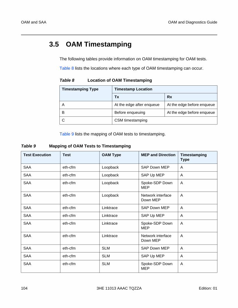
OAM and SAA
104
OAM and Diagnostics Guide
3HE 11013 AAAC TQZZA Edition: 01
3.5 OAM Timestamping
The following tables provide information on OAM timestamping for OAM tests.
Table 8 lists the locations where each type of OAM timestamping can occur.
Table 9 lists the mapping of OAM tests to timestamping.
Table 8 Location of OAM Timestamping
Timestamping Type Timestamp Location
Tx Rx
A At the edge after enqueue At the edge before enqueue
B Before enqueuing At the edge before enqueue
C CSM timestamping
Table 9 Mapping of OAM Tests to Timestamping
Test Execution Test OAM Type MEP and Direction Timestamping Type
SAA eth-cfm Loopback SAP Down MEP A
SAA eth-cfm Loopback SAP Up MEP A
SAA eth-cfm Loopback Spoke-SDP Down MEP
A
SAA eth-cfm Loopback Network interface Down MEP
A
SAA eth-cfm Linktrace SAP Down MEP A
SAA eth-cfm Linktrace SAP Up MEP A
SAA eth-cfm Linktrace Spoke-SDP Down MEP
A
SAA eth-cfm Linktrace Network interface Down MEP
A
SAA eth-cfm SLM SAP Down MEP A
SAA eth-cfm SLM SAP Up MEP A
SAA eth-cfm SLM Spoke-SDP Down MEP
A
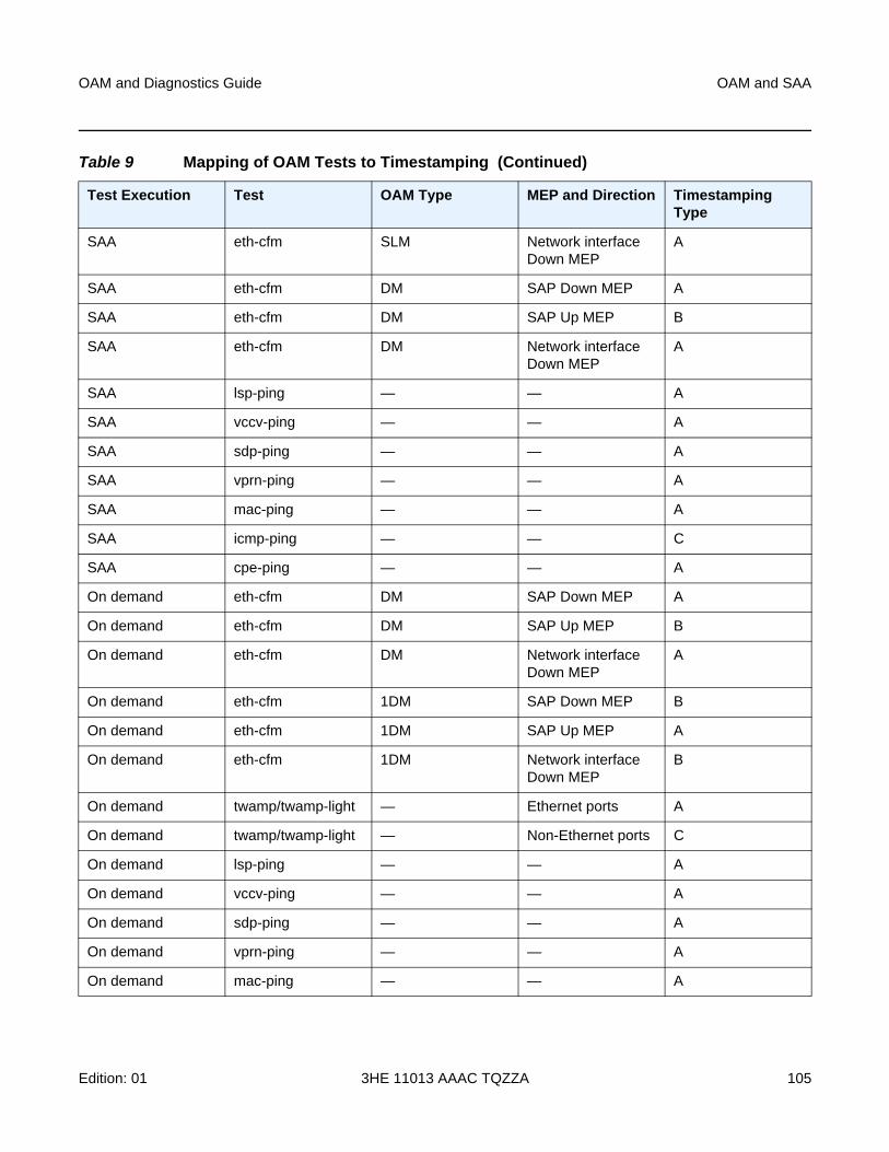
OAM and Diagnostics Guide OAM and SAA
Edition: 01 3HE 11013 AAAC TQZZA 105
SAA eth-cfm SLM Network interface Down MEP
A
SAA eth-cfm DM SAP Down MEP A
SAA eth-cfm DM SAP Up MEP B
SAA eth-cfm DM Network interface Down MEP
A
SAA lsp-ping — — A
SAA vccv-ping — — A
SAA sdp-ping — — A
SAA vprn-ping — — A
SAA mac-ping — — A
SAA icmp-ping — — C
SAA cpe-ping — — A
On demand eth-cfm DM SAP Down MEP A
On demand eth-cfm DM SAP Up MEP B
On demand eth-cfm DM Network interface Down MEP
A
On demand eth-cfm 1DM SAP Down MEP B
On demand eth-cfm 1DM SAP Up MEP A
On demand eth-cfm 1DM Network interface Down MEP
B
On demand twamp/twamp-light — Ethernet ports A
On demand twamp/twamp-light — Non-Ethernet ports C
On demand lsp-ping — — A
On demand vccv-ping — — A
On demand sdp-ping — — A
On demand vprn-ping — — A
On demand mac-ping — — A
Table 9 Mapping of OAM Tests to Timestamping (Continued)
Test Execution Test OAM Type MEP and Direction Timestamping Type
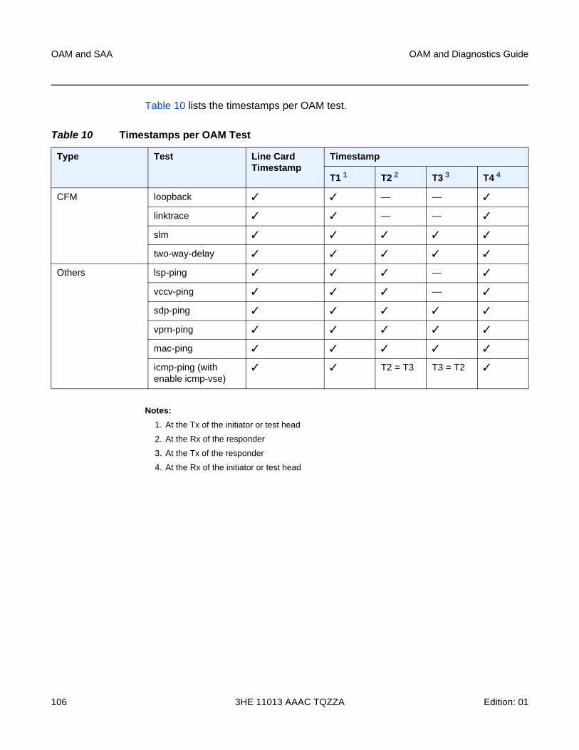
OAM and SAA
106
OAM and Diagnostics Guide
3HE 11013 AAAC TQZZA Edition: 01
Table 10 lists the timestamps per OAM test.
Notes:
1. At the Tx of the initiator or test head
2. At the Rx of the responder
3. At the Tx of the responder
4. At the Rx of the initiator or test head
Table 10 Timestamps per OAM Test
Type Test Line Card Timestamp
Timestamp
T1 1 T2 2 T3 3 T4 4
CFM loopback ✓ ✓ — — ✓
linktrace ✓ ✓ — — ✓
slm ✓ ✓ ✓ ✓ ✓
two-way-delay ✓ ✓ ✓ ✓ ✓
Others lsp-ping ✓ ✓ ✓ — ✓
vccv-ping ✓ ✓ ✓ — ✓
sdp-ping ✓ ✓ ✓ ✓ ✓
vprn-ping ✓ ✓ ✓ ✓ ✓
mac-ping ✓ ✓ ✓ ✓ ✓
icmp-ping (with enable icmp-vse)
✓ ✓ T2 = T3 T3 = T2 ✓
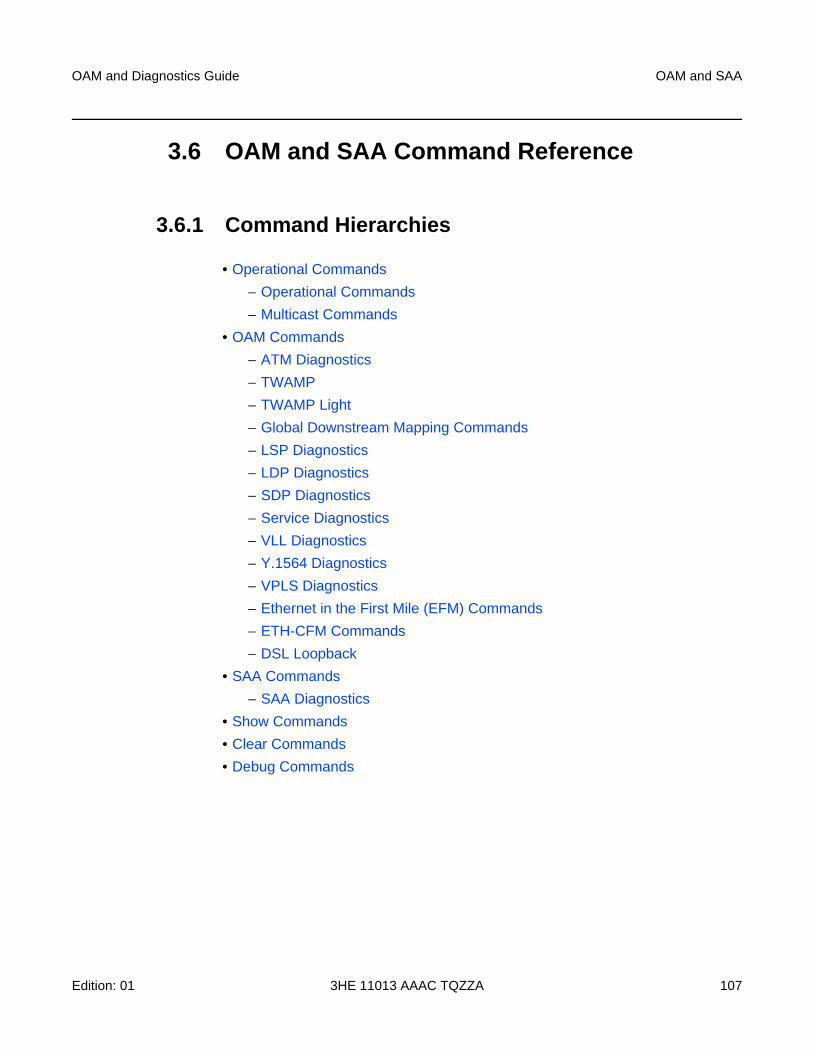
OAM and Diagnostics Guide OAM and SAA
Edition: 01 3HE 11013 AAAC TQZZA 107
3.6 OAM and SAA Command Reference
3.6.1 Command Hierarchies
• Operational Commands
− Operational Commands
− Multicast Commands
• OAM Commands
− ATM Diagnostics
− TWAMP
− TWAMP Light
− Global Downstream Mapping Commands
− LSP Diagnostics
− LDP Diagnostics
− SDP Diagnostics
− Service Diagnostics
− VLL Diagnostics
− Y.1564 Diagnostics
− VPLS Diagnostics
− Ethernet in the First Mile (EFM) Commands
− ETH-CFM Commands
− DSL Loopback
• SAA Commands
− SAA Diagnostics
• Show Commands
• Clear Commands
• Debug Commands
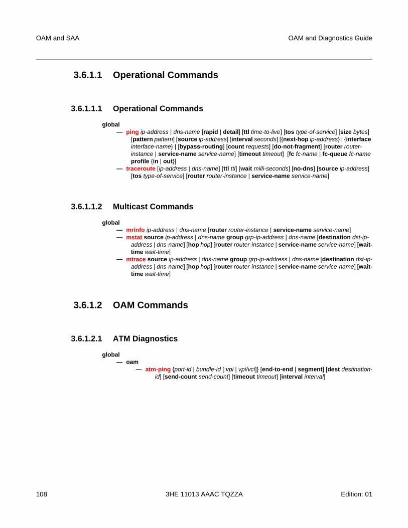
OAM and SAA
108
OAM and Diagnostics Guide
3HE 11013 AAAC TQZZA Edition: 01
3.6.1.1 Operational Commands
3.6.1.1.1 Operational Commands
global— ping ip-address | dns-name [rapid | detail] [ttl time-to-live] [tos type-of-service] [size bytes]
[pattern pattern] [source ip-address] [interval seconds] [{next-hop ip-address} | {interface interface-name} | [bypass-routing] [count requests] [do-not-fragment] [router router-instance | service-name service-name] [timeout timeout] [fc fc-name | fc-queue fc-name profile {in | out}]
— traceroute [ip-address | dns-name] [ttl ttl] [wait milli-seconds] [no-dns] [source ip-address] [tos type-of-service] [router router-instance | service-name service-name]
3.6.1.1.2 Multicast Commands
global— mrinfo ip-address | dns-name [router router-instance | service-name service-name]— mstat source ip-address | dns-name group grp-ip-address | dns-name [destination dst-ip-
address | dns-name] [hop hop] [router router-instance | service-name service-name] [wait-time wait-time]
— mtrace source ip-address | dns-name group grp-ip-address | dns-name [destination dst-ip-address | dns-name] [hop hop] [router router-instance | service-name service-name] [wait-time wait-time]
3.6.1.2 OAM Commands
3.6.1.2.1 ATM Diagnostics
global— oam
— atm-ping {port-id | bundle-id [:vpi | vpi/vci]} [end-to-end | segment] [dest destination-id] [send-count send-count] [timeout timeout] [interval interval]
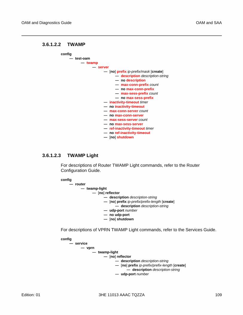
OAM and Diagnostics Guide OAM and SAA
Edition: 01 3HE 11013 AAAC TQZZA 109
3.6.1.2.2 TWAMP
config— test-oam
— twamp — server
— [no] prefix ip-prefix/mask [create]— description description-string— no description — max-conn-prefix count— no max-conn-prefix — max-sess-prefix count— no max-sess-prefix
— inactivity-timeout timer— no inactivity-timeout — max-conn-server count— no max-conn-server — max-sess-server count— no max-sess-server— ref-inactivity-timeout timer— no ref-inactivity-timeout— [no] shutdown
3.6.1.2.3 TWAMP Light
For descriptions of Router TWAMP Light commands, refer to the Router Configuration Guide.
config— router
— twamp-light— [no] reflector
— description description-string— [no] prefix ip-prefix/prefix-length [create]
— description description-string— udp-port number— no udp-port — [no] shutdown
For descriptions of VPRN TWAMP Light commands, refer to the Services Guide.
config— service
— vprn— twamp-light
— [no] reflector— description description-string— [no] prefix ip-prefix/prefix-length [create]
— description description-string— udp-port number

OAM and SAA
110
OAM and Diagnostics Guide
3HE 11013 AAAC TQZZA Edition: 01
— no udp-port — [no] shutdown
config— test-oam
— twamp — twamp-light
— inactivity-timeout seconds— no inactivity-timeout
3.6.1.2.4 Global Downstream Mapping Commands
config— test-oam
— mpls-echo-request-downstream-map {dsmap | ddmap}
3.6.1.2.5 LSP Diagnostics
global— oam
— lsp-ping lsp-name [path path-name] — lsp-ping bgp-label prefix ip-prefix/mask [path-destination ip-address [interface if-
name | next-hop ip-address]] — lsp-ping prefix ip-prefix/mask [path-destination ip-address [interface if-name | next-
hop ip-address]]— options common to all lsp-ping cases:
[fc fc-name [profile {in | out}]] [interval interval] [send-count send-count] [size octets] [src-ip-address ip-address] [timeout timeout] [ttl label-ttl]
— lsp-trace lsp-name [path path-name] — lsp-trace bgp-label prefix ip-prefix/mask [path-destination ip-address [interface if-
name | next-hop ip-address]] — lsp-trace prefix ip-prefix/mask [path-destination ip-address [interface if-name |
next-hop ip-address]]— options common to all lsp-trace cases:
[downstream-map-tlv downstream-map-tlv] [fc fc-name [profile {in | out}]] [interval interval] [max-fail no-response-count] [max-ttl max-label-ttl] [min-ttl min-label-ttl] [probe-count probes-per-hop] [size octets] [src-ip-address ip-address] [timeout timeout]
— p2mp-lsp-ping {ldp p2mp-identifier [sender-addr ip-address] [leaf-addr ip-address[...up to 5 max]]} [fc fc-name [profile {in | out}]] [size octets] [timeout timeout] [detail]
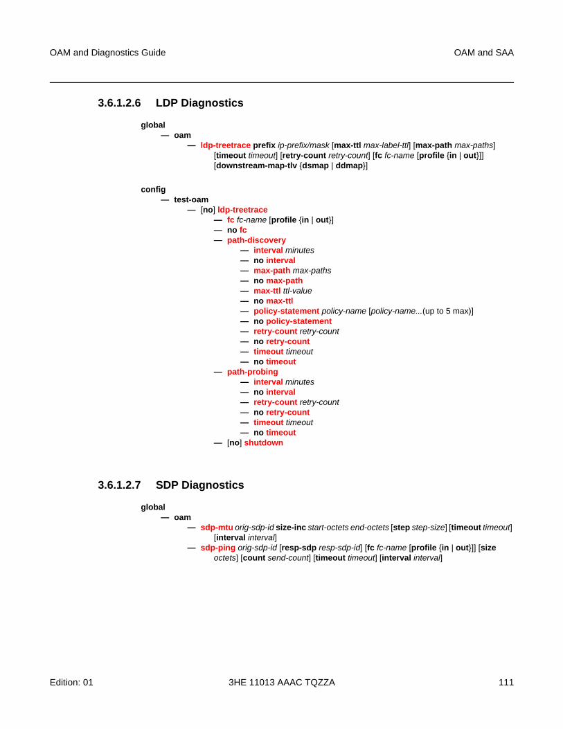
OAM and Diagnostics Guide OAM and SAA
Edition: 01 3HE 11013 AAAC TQZZA 111
3.6.1.2.6 LDP Diagnostics
global— oam
— ldp-treetrace prefix ip-prefix/mask [max-ttl max-label-ttl] [max-path max-paths] [timeout timeout] [retry-count retry-count] [fc fc-name [profile {in | out}]] [downstream-map-tlv {dsmap | ddmap}]
config— test-oam
— [no] ldp-treetrace— fc fc-name [profile {in | out}]— no fc— path-discovery
— interval minutes— no interval— max-path max-paths— no max-path— max-ttl ttl-value— no max-ttl— policy-statement policy-name [policy-name...(up to 5 max)]— no policy-statement— retry-count retry-count— no retry-count— timeout timeout— no timeout
— path-probing— interval minutes— no interval — retry-count retry-count— no retry-count — timeout timeout— no timeout
— [no] shutdown
3.6.1.2.7 SDP Diagnostics
global— oam
— sdp-mtu orig-sdp-id size-inc start-octets end-octets [step step-size] [timeout timeout] [interval interval]
— sdp-ping orig-sdp-id [resp-sdp resp-sdp-id] [fc fc-name [profile {in | out}]] [size octets] [count send-count] [timeout timeout] [interval interval]
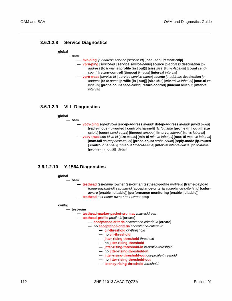
OAM and SAA
112
OAM and Diagnostics Guide
3HE 11013 AAAC TQZZA Edition: 01
3.6.1.2.8 Service Diagnostics
global— oam
— svc-ping ip-address service [service-id] [local-sdp] [remote-sdp]— vprn-ping [service-id | service service-name] source ip-address destination ip-
address [fc fc-name [profile {in | out}]] [size size] [ttl vc-label-ttl] [count send-count] [return-control] [timeout timeout] [interval interval]
— vprn-trace [service-id | service service-name] source ip-address destination ip-address [fc fc-name [profile {in | out}]] [size size] [min-ttl vc-label-ttl] [max-ttl vc-label-ttl] [probe-count send-count] [return-control] [timeout timeout] [interval interval]
3.6.1.2.9 VLL Diagnostics
global— oam
— vccv-ping sdp-id:vc-id [src-ip-address ip-addr dst-ip-address ip-addr pw-id pw-id] [reply-mode {ip-routed | control-channel}] [fc fc-name [profile {in | out}]] [size octets] [count send-count] [timeout timeout] [interval interval] [ttl vc-label-ttl]
— vccv-trace sdp-id:vc-id [size octets] [min-ttl min-vc-label-ttl] [max-ttl max-vc-label-ttl] [max-fail no-response-count] [probe-count probe-count] [reply-mode {ip-routed | control-channel}] [timeout timeout-value] [interval interval-value] [fc fc-name [profile {in | out}]] [detail]
3.6.1.2.10 Y.1564 Diagnostics
global— oam
— testhead test-name [owner test-owner] testhead-profile profile-id [frame-payload frame-payload-id] sap sap-id [acceptance-criteria acceptance-criteria-id] [color-aware {enable | disable}] [performance-monitoring {enable | disable}]
— testhead test-name owner test-owner stop
config— test-oam
— testhead-marker-packet-src-mac mac-address— testhead-profile profile-id [create]
— acceptance-criteria acceptance-criteria-id [create]— no acceptance-criteria acceptance-criteria-id
— cir-threshold cir-threshold— no cir-threshold — jitter-rising-threshold threshold— no jitter-rising-threshold — jitter-rising-threshold-in in-profile-threshold— no jitter-rising-threshold-in — jitter-rising-threshold-out out-profile-threshold— no jitter-rising-threshold-out — latency-rising-threshold threshold
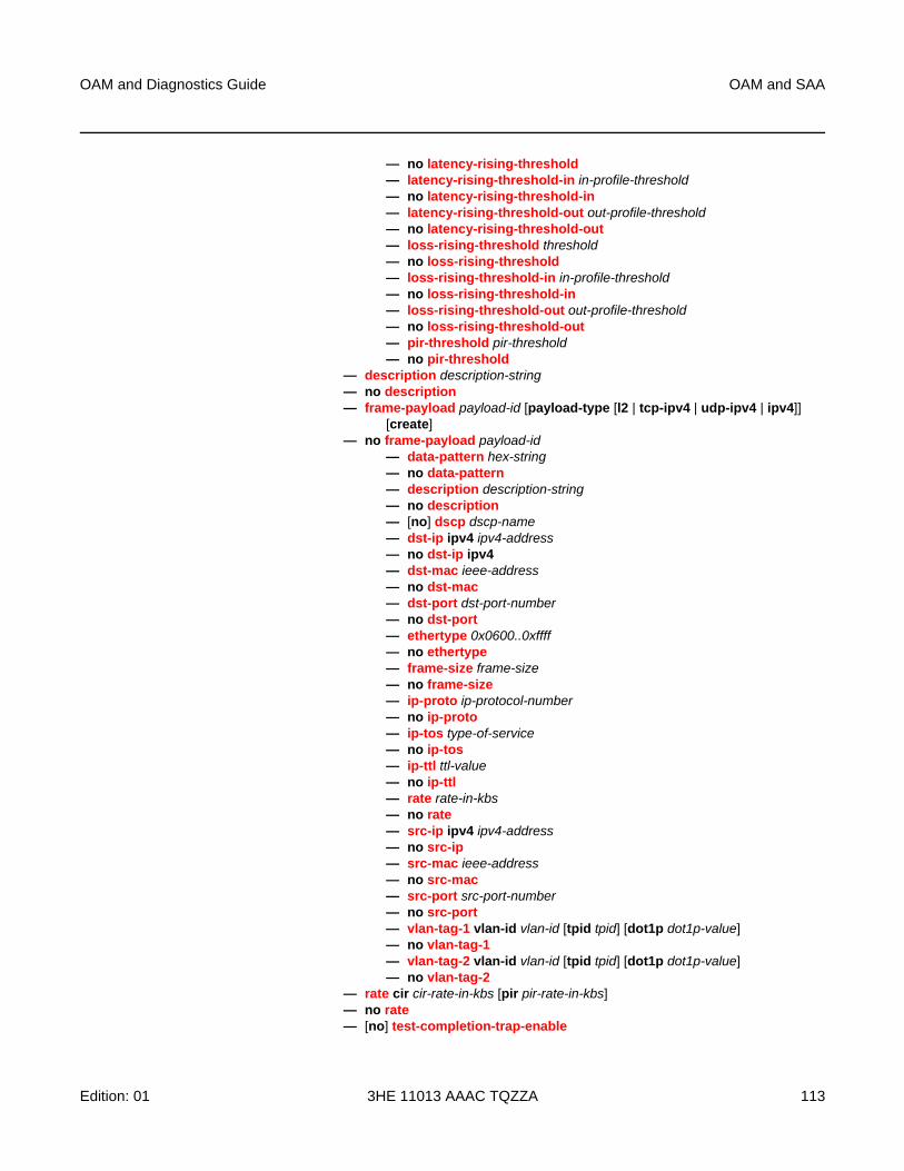
OAM and Diagnostics Guide OAM and SAA
Edition: 01 3HE 11013 AAAC TQZZA 113
— no latency-rising-threshold — latency-rising-threshold-in in-profile-threshold— no latency-rising-threshold-in — latency-rising-threshold-out out-profile-threshold— no latency-rising-threshold-out — loss-rising-threshold threshold— no loss-rising-threshold — loss-rising-threshold-in in-profile-threshold— no loss-rising-threshold-in — loss-rising-threshold-out out-profile-threshold— no loss-rising-threshold-out — pir-threshold pir-threshold— no pir-threshold
— description description-string— no description — frame-payload payload-id [payload-type [l2 | tcp-ipv4 | udp-ipv4 | ipv4]]
[create]— no frame-payload payload-id
— data-pattern hex-string— no data-pattern — description description-string— no description — [no] dscp dscp-name— dst-ip ipv4 ipv4-address— no dst-ip ipv4 — dst-mac ieee-address— no dst-mac— dst-port dst-port-number— no dst-port — ethertype 0x0600..0xffff— no ethertype — frame-size frame-size— no frame-size — ip-proto ip-protocol-number— no ip-proto — ip-tos type-of-service— no ip-tos — ip-ttl ttl-value— no ip-ttl — rate rate-in-kbs— no rate — src-ip ipv4 ipv4-address— no src-ip — src-mac ieee-address— no src-mac— src-port src-port-number— no src-port — vlan-tag-1 vlan-id vlan-id [tpid tpid] [dot1p dot1p-value]— no vlan-tag-1— vlan-tag-2 vlan-id vlan-id [tpid tpid] [dot1p dot1p-value]— no vlan-tag-2
— rate cir cir-rate-in-kbs [pir pir-rate-in-kbs]— no rate— [no] test-completion-trap-enable
OAM and SAA
114
OAM and Diagnostics Guide
3HE 11013 AAAC TQZZA Edition: 01
— test-duration {[hours hours] [minutes minutes] [seconds seconds]}— no test-duration
— config— service
— [no] epipe service-id [customer customer-id] [vpn vpn-id] [vc-switching]— sap sap-id [no-endpoint]
— loopback {line | internal} {timer seconds | persistent} [swap-src-dst-mac]
— no loopback
3.6.1.2.11 VPLS Diagnostics
global— oam
— cpe-ping service service-id destination ip-address [source ip-address] [source-mac ieee-address] [fc fc-name [profile [in | out]] [ttl vc-label-ttl] [count send-count] [send-control] [return-control] [timeout timeout] [interval interval]
— mac-ping service service-id destination dst-ieee-address [source src-ieee-address] [fc fc-name [profile {in | out}]] [ttl vc-label-ttl] [count send-count] [send-control] [return-control] [interval interval] [timeout timeout]
— mac-populate service-id mac ieee-address [flood] [age seconds] [force] [target-sap sap-id] [send-control]
— mac-purge service-id target ieee-address [flood] [send-control] [register] [force]— mac-trace service service-id destination ieee-address [source ieee-address] [fc fc-
name [profile {in | out}]] [size octets] [min-ttl vc-label-ttl] [max-ttl vc-label-ttl] [probe-count send-count] [send-control] [return-control] [interval interval] [timeout timeout]
3.6.1.2.12 Ethernet in the First Mile (EFM) Commands
global— oam
— efm port-id— local-loopback {start | stop}— remote-loopback {start | stop}
config— [no] port {port-id}
— ethernet— efm-oam
— [no] accept-remote-loopback— hold-time time-value— no hold-time— mode {active | passive}— [no] shutdown— [no] transmit-interval interval [multiplier multiplier]— [no] tunneling
OAM and Diagnostics Guide OAM and SAA
Edition: 01 3HE 11013 AAAC TQZZA 115
3.6.1.2.13 ETH-CFM Commands
global— oam
— eth-cfm— eth-test mac-address mep mep-id domain md-index association ma-index
[priority priority] [data-length data-length] — linktrace mac-address mep mep-id domain md-index association ma-index
[ttl ttl-value]— loopback mac-address mep mep-id domain md-index association ma-index
[send-count send-count] [size data-size] [priority priority]— one-way-delay-test mac-address mep mep-id domain md-index association
ma-index [priority priority] — single-ended-loss-test mac-address mep mep-id domain md-index
association ma-index [priority priority] [interval {100ms | 1s}] [send-count send-count]
— two-way-delay-test mac-address mep mep-id domain md-index association ma-index [priority priority]
— two-way-slm-test mac-address mep mep-id domain md-index association ma-index [priority priority] [send-count send-count] [size data-size] [timeout timeout] [interval interval]
config— eth-cfm
— domain md-index [format {dns | mac | none | string}] name md-name level level— domain md-index— no domain md-index
— association ma-index [format {icc-based | integer | string | vid | vpn-id}] name ma-name
— association ma-index— no association ma-index
— [no] bridge-identifier bridge-id— vlan vlan-id— no vlan
— ccm-interval {10ms | 100ms | 1 | 10 | 60 | 600}— no ccm-interval
— [no] remote-mepid mep-id— slm
— inactivity-timer timeout— no inactivity-timer
config— [no] port {port-id}
— ethernet— cfm-loopback priority {low | high | dot1p} [match-vlan {vlan-range | none}]— no cfm-loopback
OAM and SAA
116
OAM and Diagnostics Guide
3HE 11013 AAAC TQZZA Edition: 01
config— service
— [no] epipe service-id [customer customer-id] [create] [vpn vpn-id]— sap sap-id [create]
— eth-cfm— [no] hold-mep-up-on-failure — mep mep-id domain md-index association ma-index [direction
{up | down}]— no mep mep-id domain md-index association ma-index
— [no] ais-enable— client-meg-level [level [level ...]]— no client-meg-level— interval [1 | 60]— no interval— priority priority-value— no priority
— [no] ccm-enable— ccm-ltm-priority priority— no ccm-ltm-priority— description description-string— no description— [no] dual-ended-loss-test-enable
— alarm-threshold percentage— no alarm-threshold— alarm-clear-threshold percentage— no alarm-clear-threshold
— [no] eth-test-enable— bit-error-threshold bit-errors— [no] test-pattern {all-zeros | all-ones} [crc-
enable]— low-priority-defect {allDef | macRemErrXcon |
remErrXcon | errXcon | xcon | noXcon}— one-way-delay-threshold seconds— [no] shutdown
— spoke-sdp sdp-id:vc-id [vc-type {ether | vlan}] [create] [no-endpoint]— spoke-sdp sdp-id:vc-id [vc-type {ether | vlan}] [create] endpoint endpoint-
name— eth-cfm
— mep mep-id domain md-index association ma-index [direction {up | down}]
— no mep mep-id domain md-index association ma-index— [no] ccm-enable— ccm-ltm-priority priority— [no] ccm-ltm-priority— description description-string— no description— low-priority-defect {allDef | macRemErrXcon |
remErrXcon | errXcon | xcon | noXcon}— [no] shutdown
OAM and Diagnostics Guide OAM and SAA
Edition: 01 3HE 11013 AAAC TQZZA 117
config— router [router-name]
— interface ip-int-name— eth-cfm
— mep mep-id domain md-index association ma-index— no mep mep-id domain md-index association ma-index
— [no] ccm-enable— ccm-ltm-priority priority— no ccm-ltm-priority— ccm-tlv-ignore [port-status] [interface-status]— no ccm-tlv-ignore — description description-string— no description— [no] dual-ended-loss-test-enable
— alarm-threshold percentage— no alarm-threshold— alarm-clear-threshold percentage— no alarm-clear-threshold
— [no] eth-test-enable— bit-error-threshold bit-errors— [no] test-pattern {all-zeros | all-ones} [crc-enable]
— low-priority-defect {allDef | macRemErrXcon | remErrXcon | errXcon | xcon | noXcon}
— one-way-delay-threshold seconds— [no] shutdown
3.6.1.2.14 DSL Loopback
global— oam
— dsl-f5-loopback port-id
3.6.1.3 SAA Commands
config— saa
— [no] test test-name [owner test-owner]— accounting-policy acct-policy-id — no accounting-policy— description description-string— no description— no continuous— jitter-event rising-threshold threshold [falling-threshold threshold]
[direction]— no jitter-event — latency-event rising-threshold threshold [falling-threshold threshold]
[direction]— no latency-event
OAM and SAA
118
OAM and Diagnostics Guide
3HE 11013 AAAC TQZZA Edition: 01
— loss-event rising-threshold threshold [falling-threshold threshold] [direction]— no loss-event— [no] shutdown— [no] trap-gen
— [no] probe-fail-enable— probe-fail-threshold threshold — no probe-fail-threshold — [no] test-completion-enable— [no] test-fail-enable— test-fail-threshold threshold — no test-fail-threshold
— [no] type— cpe-ping service service-id destination ip-address source ip-address
[source-mac ieee-address] [fc fc-name [profile [in | out]] [ttl vc-label-ttl] [count send-count] [send-control] [return-control] [interval interval]
— eth-cfm-linktrace mac-address mep mep-id domain md-index association ma-index [ttl ttl-value] [fc fc-name [profile {in | out}]] [count send-count] [timeout timeout] [interval interval]
— eth-cfm-loopback mac-address mep mep-id domain md-index association ma-index [size data-size] [fc fc-name [profile {in | out}]] [count send-count] [timeout timeout] [interval interval]
— eth-cfm-two-way-delay mac-address mep mep-id domain md-index association ma-index [fc fc-name [profile {in | out}]] [count send-count] [timeout timeout] [interval interval]
— eth-cfm-two-way-slm mac-address mep mep-id domain md-index association ma-index [fc fc-name [profile {in | out}]] [count send-count] [size data-size] [timeout timeout] [interval interval]
— icmp-ping ip-address | dns-name [rapid] [ttl time-to-live] [tos type-of-service] [size bytes] [pattern pattern] [source ip-address] [interval seconds] [{next-hop ip-address} | {interface interface-name} | bypass-routing] [count requests] [do-not-fragment] [router router-instance | service-name service-name] [timeout timeout] [fc fc-name [profile {in | out}]]
— icmp-trace [ip-address | dns-name] [ttl time-to-live] [wait milli-seconds] [source ip-address] [tos type-of-service] [router router-instance | service-name service-name]
— lsp-ping {{lsp-name [path path-name]} | {prefix ip-prefix/mask}}[bgp-label prefix ip-prefix/mask] [fc fc-name [profile {in | out}]] [size octets] [ttl label-ttl] [send-count send-count] [timeout timeout] [interval interval] [path-destination ip-address [interface if-name | next-hop ip-address]]
— lsp-trace {{lsp-name [path path-name]} | {prefix ip-prefix/mask}} [bgp-label prefix ip-prefix/mask] [fc fc-name [profile {in | out}]] [max-fail no-response-count] [probe-count probes-per-hop] [size octets] [min-ttl min-label-ttl] [max-ttl max-label-ttl] [timeout timeout] [interval interval] [path-destination ip-address [interface if-name | next-hop ip-address]]
— mac-ping service service-id destination dst-ieee-address [source src-ieee-address] [fc fc-name [profile {in | out}]] [size octets] [ttl vc-label-ttl] [count send-count] [send-control] [return-control] [interval interval] [timeout timeout]
OAM and Diagnostics Guide OAM and SAA
Edition: 01 3HE 11013 AAAC TQZZA 119
— mac-trace service service-id destination ieee-address [source ieee-address] [fc fc-name [profile {in | out}]] [size octets] [min-ttl vc-label-ttl] [max-ttl vc-label-ttl] [probe-count send-count] [send-control] [return-control] [interval interval] [timeout timeout]
— sdp-ping orig-sdp-id [resp-sdp resp-sdp-id] [fc fc-name [profile {in | out}]] [size octets] [count send-count] [timeout timeout] [interval interval]
— vccv-ping sdp-id:vc-id [src-ip-address ip-addr dst-ip-address ip-addr pw-id pw-id] [reply-mode {ip-routed | control-channel}] [fc fc-name [profile {in | out}]] [size octets] [count send-count] [timeout timeout] [interval interval] [ttl vc-label-ttl]
— vccv-trace sdp-id:vc-id [size octets] [min-ttl min-vc-label-ttl] [max-ttl max-vc-label-ttl] [max-fail no-response-count] [probe-count probe-count] [reply-mode {ip-routed | control-channel}] [timeout timeout-value] [interval interval-value] [fc fc-name [profile {in |out}]] [detail]
— vprn-ping [service-id | service service-name] source ip-address destination ip-address [fc fc-name [profile {in | out]] [size size] [ttl vc-label-ttl] [count send-count] return-control] [timeout timeout] [interval interval]
— vprn-trace [service-id | service service-name] source ip-address destination ip-address [fc fc-name [profile {in | out}]] [size size] [min-ttl vc-label-ttl] [max-ttl vc-label-ttl] [probe-count send-count] [return-control] [timeout timeout] [interval interval]
config— system
— [no] enable-icmp-vse
3.6.1.3.1 SAA Diagnostics
global— oam
— saa test-name [owner test-owner] {start | stop}
3.6.1.4 Show Commands
show— eth-cfm
— association [ma-index] [detail]— cfm-stack-table — cfm-stack-table port [port-id [vlan vlan-id]] [level 0..7] [direction {up | down}]— cfm-stack-table sdp sdp-id[:vc-id]] [level 0..7] [direction {up | down}]— cfm-stack-table virtual [service-id] [level 0..7] — domain [md-index] [association ma-index | all-associations] [detail]— mep mep-id domain md-index association ma-index [loopback] [linktrace]— mep mep-id domain md-index association ma-index {remote-mepid mep-id |
all-remote-meps}
OAM and SAA
120
OAM and Diagnostics Guide
3HE 11013 AAAC TQZZA Edition: 01
— mep mep-id domain md-index association ma-index eth-test-results [remote-peer mac-address]
— mep mep-id domain md-index association ma-index one-way-delay-test [remote-peer mac-address]
— mep mep-id domain md-index association ma-index two-way-delay-test [remote-peer mac-address]
— mep mep-id domain md-index association ma-index single-ended-loss-test [remote-peer mac-address]
— mep mep-id domain md-index association ma-index dual-ended-loss-test [remote-peer mac-address]
— mep mep-id domain md-index association ma-index two-way-slm-test [remote-peer mac-address]
— saa [test-name [owner test-owner]]— test-oam
— ldp-treetrace [prefix ip-prefix/mask] [detail]— twamp
— server [all] [prefix ip-prefix/mask]— twamp-light
— testhead-profile profile-id— testhead [test-name owner test-name] [detail]
3.6.1.5 Clear Commands
clear— saa [test-name [owner test-owner]]— eth-cfm
— dual-ended-loss-test mep mep-id domain md-index association ma-index— test-oam
— twamp— server
— testhead [result] [test-name [owner test-owner]]
3.6.1.6 Debug Commands
debug— [no] oam
— lsp-ping-trace [tx | rx | both] [raw | detail]— no lsp-ping-trace

OAM and Diagnostics Guide OAM and SAA
Edition: 01 3HE 11013 AAAC TQZZA 121
3.6.2 Command Descriptions
• OAM and SAA Commands
• Show Commands
• Clear Commands
• Debug Commands
OAM and SAA
122
OAM and Diagnostics Guide
3HE 11013 AAAC TQZZA Edition: 01
3.6.2.1 OAM and SAA Commands
• Operational Commands
• Multicast Commands
• ATM Diagnostics
• Service Diagnostics
• EFM Commands
• ETH-CFM Commands
• DSL Commands
• SAA Commands
• Y.1564 Diagnostics
• TWAMP Commands
• Global Downstream Mapping Commands
• LDP Diagnostics
• OAM SAA Commands
OAM and Diagnostics Guide OAM and SAA
Edition: 01 3HE 11013 AAAC TQZZA 123
3.6.2.1.1 Operational Commands
ping
Syntax ping ip-address | dns-name [rapid | detail] [ttl time-to-live] [tos type-of-service] [size bytes] [pattern pattern] [source ip-address] [interval seconds] [{next-hop ip-address} | {interface interface-name} | [bypass-routing] [count requests] [do-not-fragment] [router router-instance | service-name service-name] [timeout timeout] [fc fc-name | fc-queue fc-name profile {in | out}]
Context <global>
Description This command verifies the reachability of a remote host.
Parameters ip-address — identifies the far-end IP address to which to send the ping request message
Values ipv4-address a.b.c.d
ipv6-address x:x:x:x:x:x:x:x[-interface]
x:x:x:x:x:x:d.d.d.d[-interface]
x: [0 to FFFF]H
d: [0 to 255]D
interface: 32 chars max, mandatory
for link local addresses
dns-name — identifies the DNS name of the far-end device to which to send the ping request message, expressed as a character string up to 63 characters
rapid — changes the units for the interval from seconds to hundredths of seconds
detail — displays detailed information
time-to-live — specifies the TTL value for the MPLS label, expressed as a decimal integer
Values 1 to 128
type-of-service — specifies the service type
Values 0 to 255
bytes — specifies the request packet size in bytes, expressed as a decimal integer
Values 0 to 16384
pattern — specifies the pattern that will be used to fill the date portion in a ping packet. If no pattern is specified, position information will be filled instead.
Values 0 to 65535
source ip-address — specifies the IP address to be used
Values ipv4-address a.b.c.d
OAM and SAA
124
OAM and Diagnostics Guide
3HE 11013 AAAC TQZZA Edition: 01
ipv6-address x:x:x:x:x:x:x:x (eight 16-bit pieces)
x:x:x:x:x:x:d.d.d.d
x: [0 to FFFF]H
d: [0 to 255]D
seconds — defines the minimum amount of time, expressed as a decimal integer, that must expire before the next message request is sent.
This parameter is used to override the default request message send interval. If the interval is set to 1 s, and the timeout value is set to 10 s, the maximum time between message requests is 10 s and the minimum is 1 s. This depends upon the receipt of a message reply corresponding to the outstanding message request.
Values 1 to 10000
Default 1
next-hop ip-address — displays only the static routes with the specified next-hop IP address
Values ipv4-address a.b.c.d
ipv6-address x:x:x:x:x:x:x:x (eight 16-bit pieces)
x:x:x:x:x:x:d.d.d.d
x: [0 to FFFF]H
d: [0 to 255]D
interface-name — specifies the name of an IP interface. The name must already exist in the config>router>interface context.
bypass-routing — specifies whether to send the ping request to a host on a directly attached network bypassing the routing table
requests — specifies the number of times to perform an OAM ping probe operation. Each OAM echo message request must either time out or receive a reply before the next message request is sent.
Values 1 to 100000
Default 5
do-not-fragment — sets the DF (Do not fragment) bit in the ICMP ping packet (does not apply to ICMPv6)
router-instance — specifies the router name or service ID
Values router-name: Base, management
service-id: 1 to 2147483647
Default Base
service-name — the service name, up to 64 characters
timeout — specifies the amount of time that the router will wait for a message reply after sending the message request. If the timeout expires, the requesting router assumes that the message response will not be received. Any response received after the request times out will be silently discarded.
OAM and Diagnostics Guide OAM and SAA
Edition: 01 3HE 11013 AAAC TQZZA 125
This value is used to override the default timeout value.
Values 1 to 10
Default 5
fc fc-name — specifies the forwarding class for ICMP echo-request packets, which controls the dot1p marking of packets based on the configured SAP egress or network QoS policy. The packets use the egress control queue. If the fc option is not specified, the ICMP echo-request packets use the nc forwarding class by default. The DSCP value in the ping packets is determined by the application icmp dscp setting in the sgt-qos configuration (refer to the 7705 SAR Quality of Service Guide, “Self-generated Traffic Commands”, for sgt-qos command descriptions).
Values be | l2 | af | l1 | h2 | ef | h1 | nc
Default nc
fc-queue fc-name — specifies that the ICMP echo-request packets should use the egress data queue associated with the specified fc-name rather than the egress control queue (refer to the 7705 SAR Quality of Service Guide, “SGT Redirection” for more information)
Values be | l2 | af | l1 | h2 | ef | h1 | nc
Default nc
profile {in | out} — specifies the profile state of packets assigned to the specified forwarding class; this parameter applies only when the fc-queue parameter is configured
shutdown
Syntax [no] shutdown
Context config>saa>testconfig>port>ethernet>efm-oamconfig>service>epipe>sap>eth-cfm>mepconfig>service>epipe>spoke-sdp>eth-cfm>mepconfig>router>if>eth-cfm>mepconfig>test-oam>ldp-treetraceconfig>test-oam>twamp>server
Description The shutdown command administratively disables a test. A shutdown can only be performed if a test is not executing at the time the command is entered.
When a test is created, it remains in shutdown mode until a no shutdown command is executed.
In order to modify an existing test, it must first be shut down.
When used with the ethernet>efm-oam command, shutdown enables tunneling on the port (see tunneling), and no shutdown enables Ethernet EFM OAM 802.3ah.
OAM and SAA
126
OAM and Diagnostics Guide
3HE 11013 AAAC TQZZA Edition: 01
The no form of this command sets the state of the test to operational.
Default shutdown
traceroute
Syntax traceroute [ip-address | dns-name] [ttl ttl] [wait milli-seconds] [no-dns] [source ip-address] [tos type-of-service] [router router-instance | service-name service-name]
Context <global>
Description This command determines the route to a destination address.
Parameters ip-address — specifies the far-end IP address to which to send the traceroute request message
Values ipv4-address a.b.c.d
ipv6-address x:x:x:x:x:x:x:x
x:x:x:x:x:x:d.d.d.d
x: [0 to FFFF]H
d: [0 to 255]D
dns-name — specifies the DNS name of the far-end device to which to send the traceroute request message, expressed as a character string
ttl — specifies the maximum Time-To-Live (TTL) value to include in the traceroute request, expressed as a decimal integer
Values 1 to 255
milli-seconds — specifies the time in milliseconds to wait for a response to a probe, expressed as a decimal integer
Values 10 to 60000
Default 5000
no-dns — when the no-dns keyword is specified, DNS lookups of the responding hosts will not be performed; only the IP addresses will be printed
Default DNS lookups of the responding hosts are performed
source ip-address — specifies the source IP address to use as the source of the probe packets. If the IP address is not one of the device’s interfaces, an error is returned.
Values ipv4-address a.b.c.d
ipv6-address x:x:x:x:x:x:x:x (eight 16-bit pieces)
x:x:x:x:x:x:d.d.d.d
x: [0 to FFFF]H
d: [0 to 255]D
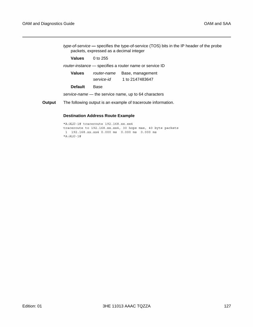
OAM and Diagnostics Guide OAM and SAA
Edition: 01 3HE 11013 AAAC TQZZA 127
type-of-service — specifies the type-of-service (TOS) bits in the IP header of the probe packets, expressed as a decimal integer
Values 0 to 255
router-instance — specifies a router name or service ID
Values router-name Base, management
service-id 1 to 2147483647
Default Base
service-name — the service name, up to 64 characters
Output The following output is an example of traceroute information.
Destination Address Route Example
*A:ALU-1# traceroute 192.168.xx.xx4traceroute to 192.168.xx.xx4, 30 hops max, 40 byte packets1 192.168.xx.xx4 0.000 ms 0.000 ms 0.000 ms
*A:ALU-1#
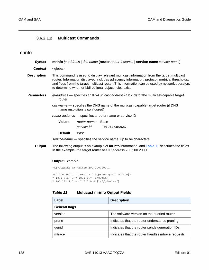
OAM and SAA
128
OAM and Diagnostics Guide
3HE 11013 AAAC TQZZA Edition: 01
3.6.2.1.2 Multicast Commands
mrinfo
Syntax mrinfo ip-address | dns-name [router router-instance | service-name service-name]
Context <global>
Description This command is used to display relevant multicast information from the target multicast router. Information displayed includes adjacency information, protocol, metrics, thresholds, and flags from the target multicast router. This information can be used by network operators to determine whether bidirectional adjacencies exist.
Parameters ip-address — specifies an IPv4 unicast address (a.b.c.d) for the multicast-capable target router
dns-name — specifies the DNS name of the multicast-capable target router (if DNS name resolution is configured)
router-instance — specifies a router name or service ID
Values router-name Base
service-id 1 to 2147483647
Default Base
service-name — specifies the service name, up to 64 characters
Output The following output is an example of mrinfo information, and Table 11 describes the fields. In the example, the target router has IP address 200.200.200.1.
Output Example
*A:7CSA:Dut-C# mrinfo 200.200.200.1
200.200.200.1 [version 0.0,prune,genid,mtrace]:? 10.1.7.1 -> ? 10.1.7.7 [1/0/pim]? 100.111.1.1 -> ? 0.0.0.0 [1/0/pim/leaf]
Table 11 Multicast mrinfo Output Fields
Label Description
General flags
version The software version on the queried router
prune Indicates that the router understands pruning
genid Indicates that the router sends generation IDs
mtrace Indicates that the router handles mtrace requests
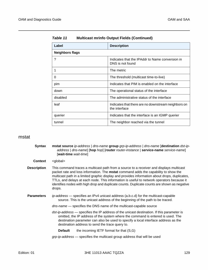
OAM and Diagnostics Guide OAM and SAA
Edition: 01 3HE 11013 AAAC TQZZA 129
mstat
Syntax mstat source ip-address | dns-name group grp-ip-address | dns-name [destination dst-ip-address | dns-name] [hop hop] [router router-instance | service-name service-name] [wait-time wait-time]
Context <global>
Description This command traces a multicast path from a source to a receiver and displays multicast packet rate and loss information. The mstat command adds the capability to show the multicast path in a limited graphic display and provides information about drops, duplicates, TTLs, and delays at each node. This information is useful to network operators because it identifies nodes with high drop and duplicate counts. Duplicate counts are shown as negative drops.
Parameters ip-address — specifies an IPv4 unicast address (a.b.c.d) for the multicast-capable source. This is the unicast address of the beginning of the path to be traced.
dns-name — specifies the DNS name of the multicast-capable source
dst-ip-address — specifies the IP address of the unicast destination. If this parameter is omitted, the IP address of the system where the command is entered is used. The destination parameter can also be used to specify a local interface address as the destination address to send the trace query to.
Default the incoming IETF format for that (S,G)
grp-ip-address — specifies the multicast group address that will be used
Neighbors flags
? Indicates that the IPAddr to Name conversion in DNS is not found
1 The metric
0 The threshold (multicast time-to-live)
pim Indicates that PIM is enabled on the interface
down The operational status of the interface
disabled The administrative status of the interface
leaf Indicates that there are no downstream neighbors on the interface
querier Indicates that the interface is an IGMP querier
tunnel The neighbor reached via the tunnel
Table 11 Multicast mrinfo Output Fields (Continued)
Label Description
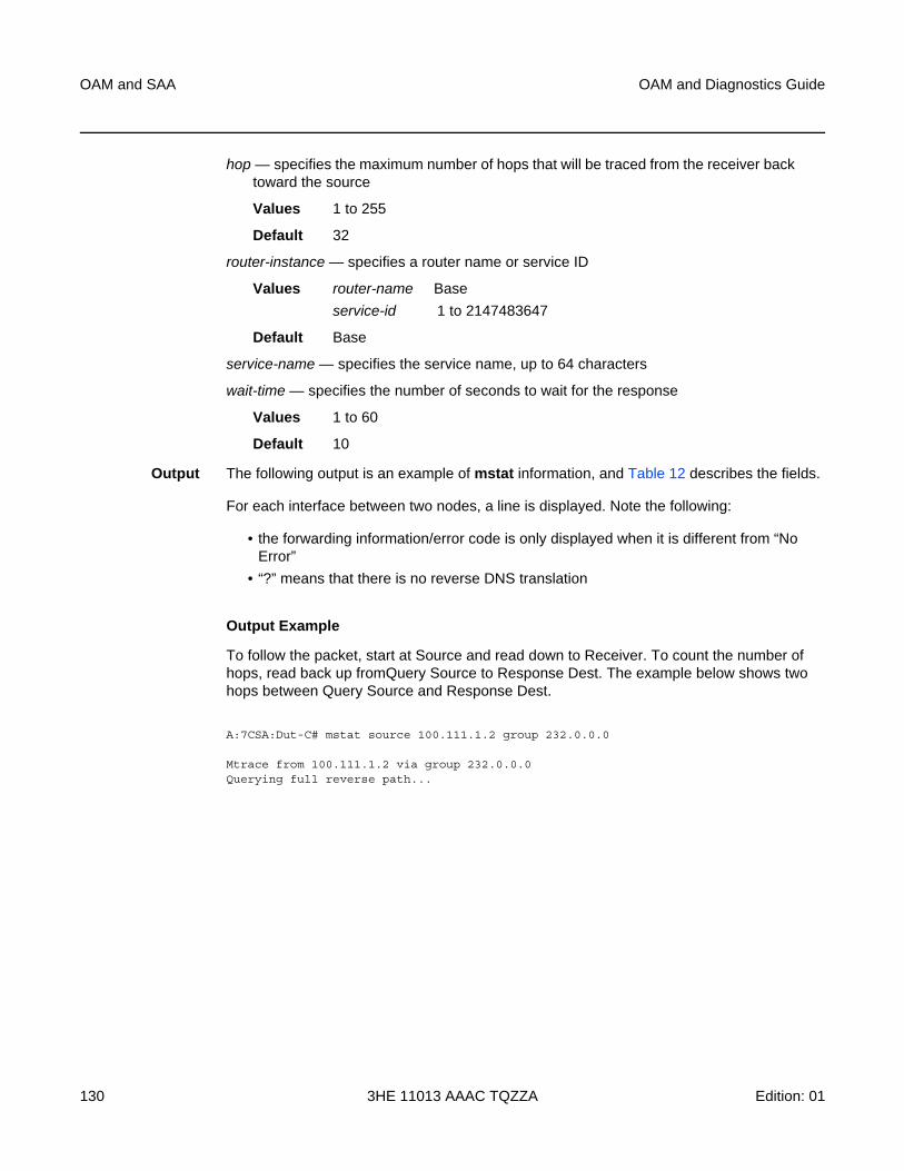
OAM and SAA
130
OAM and Diagnostics Guide
3HE 11013 AAAC TQZZA Edition: 01
hop — specifies the maximum number of hops that will be traced from the receiver back toward the source
Values 1 to 255
Default 32
router-instance — specifies a router name or service ID
Values router-name Base
service-id 1 to 2147483647
Default Base
service-name — specifies the service name, up to 64 characters
wait-time — specifies the number of seconds to wait for the response
Values 1 to 60
Default 10
Output The following output is an example of mstat information, and Table 12 describes the fields.
For each interface between two nodes, a line is displayed. Note the following:
• the forwarding information/error code is only displayed when it is different from “No Error”
• “?” means that there is no reverse DNS translation
Output Example
To follow the packet, start at Source and read down to Receiver. To count the number of hops, read back up fromQuery Source to Response Dest. The example below shows two hops between Query Source and Response Dest.
A:7CSA:Dut-C# mstat source 100.111.1.2 group 232.0.0.0
Mtrace from 100.111.1.2 via group 232.0.0.0Querying full reverse path...
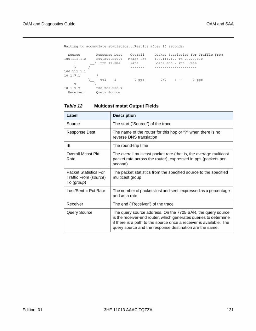
OAM and Diagnostics Guide OAM and SAA
Edition: 01 3HE 11013 AAAC TQZZA 131
Waiting to accumulate statistics...Results after 10 seconds:
Source Response Dest Overall Packet Statistics For Traffic From100.111.1.2 200.200.200.7 Mcast Pkt 100.111.1.2 To 232.0.0.0
| __/ rtt 11.0ms Rate Lost/Sent = Pct Ratev / ------- ---------------------
100.111.1.110.1.7.1 ?
| \__ ttl 2 0 pps 0/0 = -- 0 ppsv \
10.1.7.7 200.200.200.7Receiver Query Source
Table 12 Multicast mstat Output Fields
Label Description
Source The start (“Source”) of the trace
Response Dest The name of the router for this hop or “?” when there is no reverse DNS translation
rtt The round-trip time
Overall Mcast Pkt Rate
The overall multicast packet rate (that is, the average multicast packet rate across the router), expressed in pps (packets per second)
Packet Statistics For Traffic From (source) To (group)
The packet statistics from the specified source to the specified multicast group
Lost/Sent = Pct Rate The number of packets lost and sent, expressed as a percentage and as a rate
Receiver The end (“Receiver”) of the trace
Query Source The query source address. On the 7705 SAR, the query source is the receiver-end router, which generates queries to determine if there is a path to the source once a receiver is available. The query source and the response destination are the same.
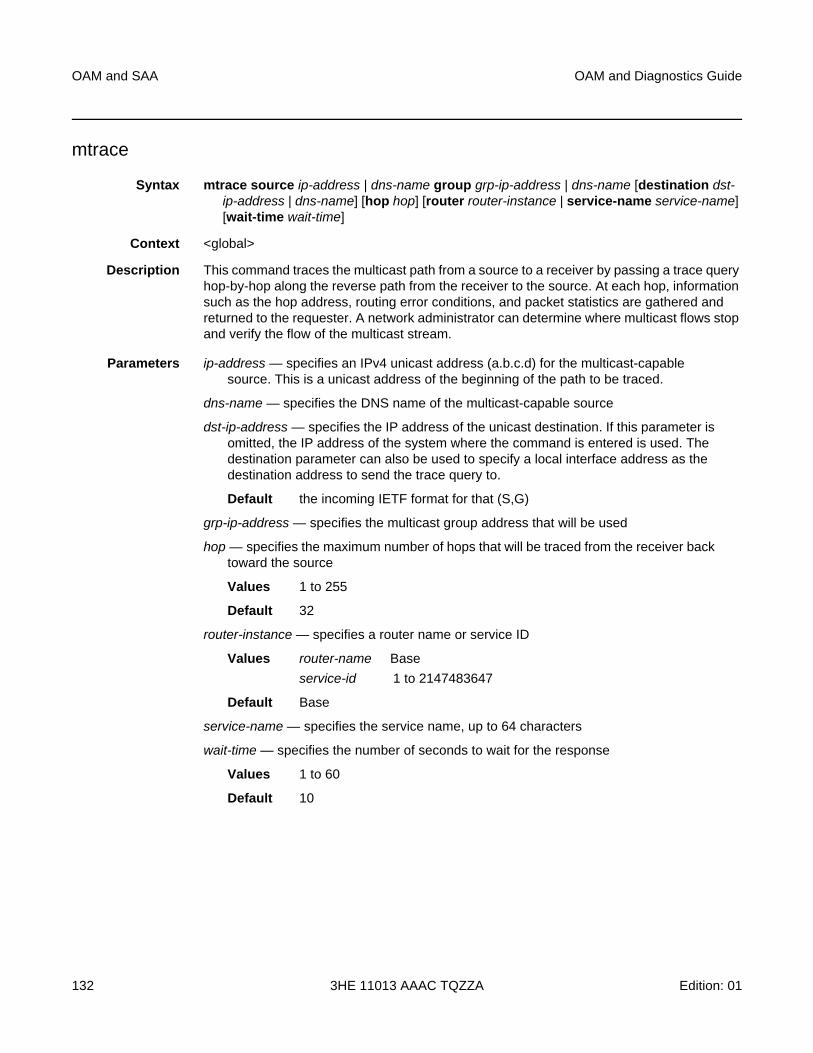
OAM and SAA
132
OAM and Diagnostics Guide
3HE 11013 AAAC TQZZA Edition: 01
mtrace
Syntax mtrace source ip-address | dns-name group grp-ip-address | dns-name [destination dst-ip-address | dns-name] [hop hop] [router router-instance | service-name service-name] [wait-time wait-time]
Context <global>
Description This command traces the multicast path from a source to a receiver by passing a trace query hop-by-hop along the reverse path from the receiver to the source. At each hop, information such as the hop address, routing error conditions, and packet statistics are gathered and returned to the requester. A network administrator can determine where multicast flows stop and verify the flow of the multicast stream.
Parameters ip-address — specifies an IPv4 unicast address (a.b.c.d) for the multicast-capable source. This is a unicast address of the beginning of the path to be traced.
dns-name — specifies the DNS name of the multicast-capable source
dst-ip-address — specifies the IP address of the unicast destination. If this parameter is omitted, the IP address of the system where the command is entered is used. The destination parameter can also be used to specify a local interface address as the destination address to send the trace query to.
Default the incoming IETF format for that (S,G)
grp-ip-address — specifies the multicast group address that will be used
hop — specifies the maximum number of hops that will be traced from the receiver back toward the source
Values 1 to 255
Default 32
router-instance — specifies a router name or service ID
Values router-name Base
service-id 1 to 2147483647
Default Base
service-name — specifies the service name, up to 64 characters
wait-time — specifies the number of seconds to wait for the response
Values 1 to 60
Default 10
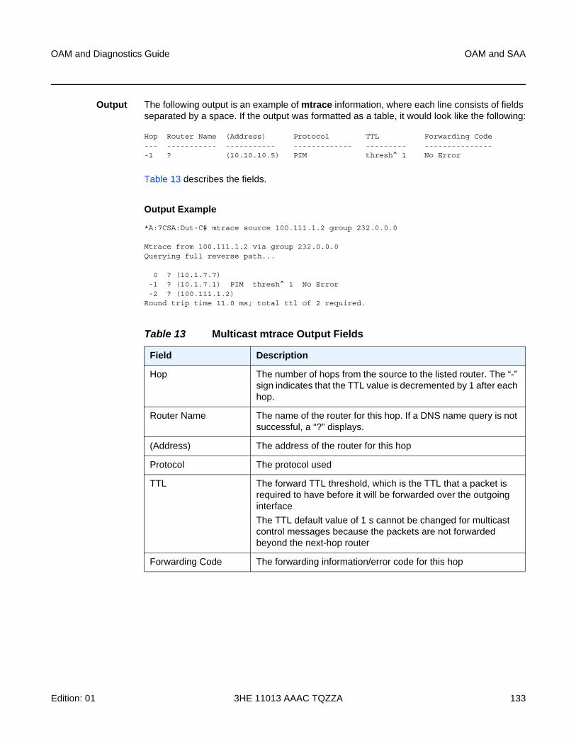
OAM and Diagnostics Guide OAM and SAA
Edition: 01 3HE 11013 AAAC TQZZA 133
Output The following output is an example of mtrace information, where each line consists of fields separated by a space. If the output was formatted as a table, it would look like the following:
Hop Router Name (Address) Protocol TTL Forwarding Code--- ----------- ----------- ------------- --------- ----------------1 ? (10.10.10.5) PIM thresh^ 1 No Error
Table 13 describes the fields.
Output Example
*A:7CSA:Dut-C# mtrace source 100.111.1.2 group 232.0.0.0
Mtrace from 100.111.1.2 via group 232.0.0.0Querying full reverse path...
0 ? (10.1.7.7)-1 ? (10.1.7.1) PIM thresh^ 1 No Error-2 ? (100.111.1.2)
Round trip time 11.0 ms; total ttl of 2 required.
Table 13 Multicast mtrace Output Fields
Field Description
Hop The number of hops from the source to the listed router. The “-” sign indicates that the TTL value is decremented by 1 after each hop.
Router Name The name of the router for this hop. If a DNS name query is not successful, a “?” displays.
(Address) The address of the router for this hop
Protocol The protocol used
TTL The forward TTL threshold, which is the TTL that a packet is required to have before it will be forwarded over the outgoing interface
The TTL default value of 1 s cannot be changed for multicast control messages because the packets are not forwarded beyond the next-hop router
Forwarding Code The forwarding information/error code for this hop
OAM and SAA
134
OAM and Diagnostics Guide
3HE 11013 AAAC TQZZA Edition: 01
3.6.2.1.3 ATM Diagnostics
atm-ping
Syntax atm-ping {port-id | bundle-id [:vpi | vpi/vci]} [end-to-end | segment] [dest destination-id] [send-count send-count] [timeout timeout] [interval interval]
Context oam
Description This command tests ATM path connectivity on an ATM VCC.
This command is not supported on ATM VCC SAPs that are members of a SAP aggregation group.
Parameters port-id:vpi/vci — specifies the ID of the access port of the target VC. This parameter is required.
Values port-id slot/mda/port
bundle-id bundle-type-slot/mda.bundle-num
bundle keyword
type ima
bundle-num 1 to 32
vpi 0 to 4095 (NNI)
0 to 255 (UNI)
vci 1, 2, 5 to 65535
end-to-end | segment — specifies whether the ATM OAM loopback cell is destined for the first segment point in the line direction or the PVCC connection endpoint
destination-id — defines the LLID field in an OAM loopback cell. If set to all 1s, only the connection end (end-to-end ping) or segment end (segment ping) will respond to the ping. If the segment parameter is specified and dest is set to a specific destination, only the destination will respond to the ping.
Values a 16-byte octet string, with each octet separated by a colon; if not specified, the value of 0x11 will be used
send-count — the number of messages to send, expressed as a decimal integer. The send-count parameter is used to override the default number of message requests sent. Each message request must either time out or receive a reply before the next message request is sent. The message interval value must be expired before the next message request is sent.
Values 1 to 100
Default 1
timeout — specifies the amount of time that the router will wait for a message reply after sending the message request. If the timeout expires, the requesting router assumes that the message response will not be received. Any response received after the request times out will be silently discarded.

OAM and Diagnostics Guide OAM and SAA
Edition: 01 3HE 11013 AAAC TQZZA 135
This value is used to override the default timeout value.
Values 1 to 10
Default 5
interval — specifies the minimum amount of time that must expire before the next message request is sent
If the interval is set to 1 s, and the timeout value is set to 10 s, then the maximum time between message requests is 10 s and the minimum is 1 s. This depends upon the receipt of a message reply corresponding to the outstanding message request.
This parameter is used to override the default request message send interval.
Values 1 to 10
Default 1
OAM and SAA
136
OAM and Diagnostics Guide
3HE 11013 AAAC TQZZA Edition: 01
3.6.2.1.4 Service Diagnostics
sdp-mtu
Syntax sdp-mtu orig-sdp-id size-inc start-octets end-octets [step step-size] [timeout timeout] [interval interval]
Context oam
Description This command performs MTU path tests on an SDP to determine the largest path-mtu supported on an SDP. The size-inc parameter can be used to easily determine the path-mtu of a given SDP-ID. The forwarding class is assumed to be Best-Effort Out-of-Profile. The message reply is returned with IP encapsulation from the far-end 7705 SAR. OAM request messages sent within an IP SDP must have the “DF” IP header bit set to 1 to prevent message fragmentation.
With each OAM echo request sent using the size-inc parameter, a response line is displayed as message output. The path MTU test displays incrementing packet sizes, the number sent at each size until a reply is received and the response message.
As the request message is sent, its size value is displayed followed by a period for each request sent of that size. Up to three requests will be sent unless a valid response is received for one of the requests at that size. Once a response is received, the next size message is sent. The response message indicates the result of the message request.
After the last reply has been received or a response timeout occurs, the maximum size message replied to indicates the largest size OAM request message that received a valid reply.
To terminate an sdp-mtu in progress, use the CLI break sequence <Ctrl-C>.
Parameters orig-sdp-id — specifies the SDP-ID to be used by sdp-mtu, expressed as a decimal integer. The far-end address of the specified SDP-ID is the expected responder-id within each reply received. The specified SDP-ID defines the SDP tunnel encapsulation used to reach the far end — GRE, IP, or MPLS. If orig-sdp-id is invalid or administratively down or unavailable for some reason, the SDP echo request message is not sent and an appropriate error message is displayed (once the interval timer expires, sdp-mtu will attempt to send the next request if required).
Values 1 to 17407
Note: The sdp-mtu command probes the far-end port using the configured MTU of the near-end port, not the configured MTU of the far-end port. For example, a far-end port that is physically capable of receiving jumbo frames would respond to sdp-mtu probes up to the jumbo frame size, regardless of the configured MTU of the far-end port. This assumes that the intermediate transport network can switch frames of this size.
OAM and Diagnostics Guide OAM and SAA
Edition: 01 3HE 11013 AAAC TQZZA 137
start-octets end-octets — indicates that an incremental path MTU test will be performed by sending a series of message requests with increasing MTU sizes
start-octets — specifies the beginning size in octets of the first message sent for an incremental MTU test, expressed as a decimal integer
Values 72 to 9702
end-octets — specifies the ending size in octets of the last message sent for an incremental MTU test, expressed as a decimal integer. The specified value must be greater than start-octets.
Values 72 to 9702
step-size — specifies the number of octets to increment the message size request for each message sent for an incremental MTU test, expressed as a decimal integer. The next size message will not be sent until a reply is received or three messages have timed out at the current size.
If the incremented size exceeds the end-octets value, no more messages will be sent.
Values 1 to 512
Default 32
timeout — specifies the amount of time that the router will wait for a message reply after sending the message request. If the timeout expires, the requesting router assumes that the message response will not be received. A “request timeout” message is displayed by the CLI for each message request sent that expires. Any response received after the request times out will be silently discarded.
This value is used to override the default timeout value.
Values 1 to 10
Default 5
interval — defines the minimum amount of time that must expire before the next message request is sent.
If the interval is set to 1 s, and the timeout value is set to 10 s, then the maximum time between message requests is 10 s and the minimum is 1 s. This depends upon the receipt of a message reply corresponding to the outstanding message request.
This parameter is used to override the default request message send interval.
Values 1 to 10
Default 1
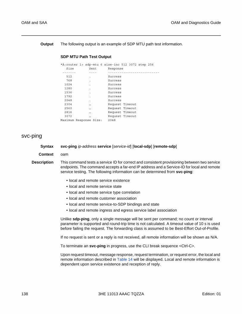
OAM and SAA
138
OAM and Diagnostics Guide
3HE 11013 AAAC TQZZA Edition: 01
Output The following output is an example of SDP MTU path test information.
SDP MTU Path Test Output
*A:router 1> sdp-mtu 6 size-inc 512 3072 step 256Size Sent Response
------- ---- ---------------------------512 . Success768 . Success
1024 . Success1280 . Success1536 . Success1792 . Success2048 . Success2304 … Request Timeout2560 … Request Timeout2816 … Request Timeout3072 … Request Timeout
Maximum Response Size: 2048
svc-ping
Syntax svc-ping ip-address service [service-id] [local-sdp] [remote-sdp]
Context oam
Description This command tests a service ID for correct and consistent provisioning between two service endpoints. The command accepts a far-end IP address and a Service-ID for local and remote service testing. The following information can be determined from svc-ping:
• local and remote service existence
• local and remote service state
• local and remote service type correlation
• local and remote customer association
• local and remote service-to-SDP bindings and state
• local and remote ingress and egress service label association
Unlike sdp-ping, only a single message will be sent per command; no count or interval parameter is supported and round-trip time is not calculated. A timeout value of 10 s is used before failing the request. The forwarding class is assumed to be Best-Effort Out-of-Profile.
If no request is sent or a reply is not received, all remote information will be shown as N/A.
To terminate an svc-ping in progress, use the CLI break sequence <Ctrl-C>.
Upon request timeout, message response, request termination, or request error, the local and remote information described in Table 14 will be displayed. Local and remote information is dependent upon service existence and reception of reply.
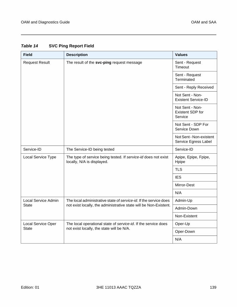
OAM and Diagnostics Guide OAM and SAA
Edition: 01 3HE 11013 AAAC TQZZA 139
Table 14 SVC Ping Report Field
Field Description Values
Request Result The result of the svc-ping request message Sent - Request Timeout
Sent - Request Terminated
Sent - Reply Received
Not Sent - Non-Existent Service-ID
Not Sent - Non-Existent SDP for Service
Not Sent - SDP For Service Down
Not Sent - Non-existent Service Egress Label
Service-ID The Service-ID being tested Service-ID
Local Service Type The type of service being tested. If service-id does not exist locally, N/A is displayed.
Apipe, Epipe, Fpipe, Hpipe
TLS
IES
Mirror-Dest
N/A
Local Service Admin State
The local administrative state of service-id. If the service does not exist locally, the administrative state will be Non-Existent.
Admin-Up
Admin-Down
Non-Existent
Local Service Oper State
The local operational state of service-id. If the service does not exist locally, the state will be N/A.
Oper-Up
Oper-Down
N/A
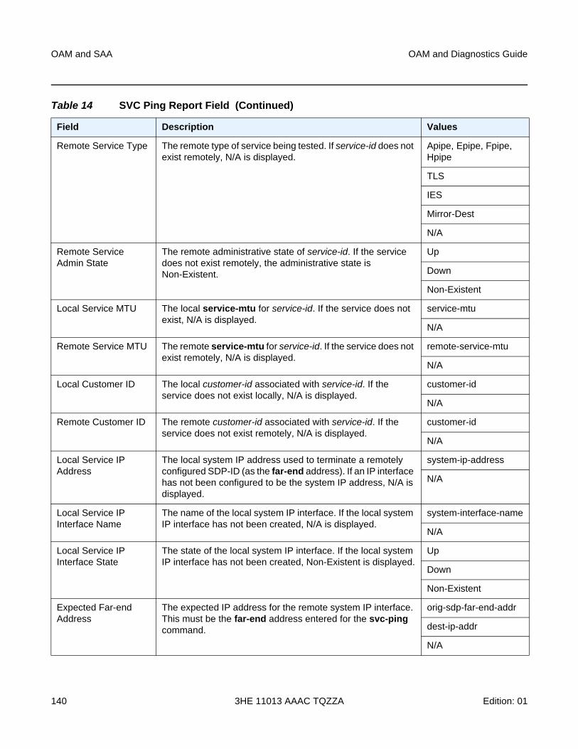
OAM and SAA
140
OAM and Diagnostics Guide
3HE 11013 AAAC TQZZA Edition: 01
Remote Service Type The remote type of service being tested. If service-id does not exist remotely, N/A is displayed.
Apipe, Epipe, Fpipe, Hpipe
TLS
IES
Mirror-Dest
N/A
Remote Service Admin State
The remote administrative state of service-id. If the service does not exist remotely, the administrative state is Non-Existent.
Up
Down
Non-Existent
Local Service MTU The local service-mtu for service-id. If the service does not exist, N/A is displayed.
service-mtu
N/A
Remote Service MTU The remote service-mtu for service-id. If the service does not exist remotely, N/A is displayed.
remote-service-mtu
N/A
Local Customer ID The local customer-id associated with service-id. If the service does not exist locally, N/A is displayed.
customer-id
N/A
Remote Customer ID The remote customer-id associated with service-id. If the service does not exist remotely, N/A is displayed.
customer-id
N/A
Local Service IP Address
The local system IP address used to terminate a remotely configured SDP-ID (as the far-end address). If an IP interface has not been configured to be the system IP address, N/A is displayed.
system-ip-address
N/A
Local Service IP Interface Name
The name of the local system IP interface. If the local system IP interface has not been created, N/A is displayed.
system-interface-name
N/A
Local Service IP Interface State
The state of the local system IP interface. If the local system IP interface has not been created, Non-Existent is displayed.
Up
Down
Non-Existent
Expected Far-end Address
The expected IP address for the remote system IP interface. This must be the far-end address entered for the svc-ping command.
orig-sdp-far-end-addr
dest-ip-addr
N/A
Table 14 SVC Ping Report Field (Continued)
Field Description Values
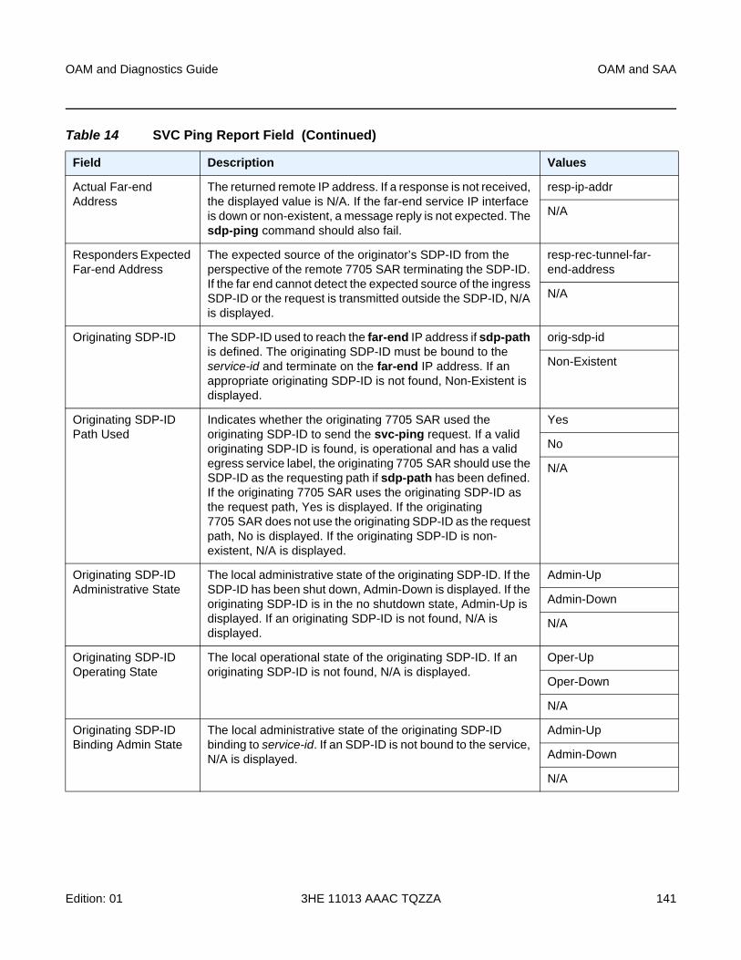
OAM and Diagnostics Guide OAM and SAA
Edition: 01 3HE 11013 AAAC TQZZA 141
Actual Far-end Address
The returned remote IP address. If a response is not received, the displayed value is N/A. If the far-end service IP interface is down or non-existent, a message reply is not expected. The sdp-ping command should also fail.
resp-ip-addr
N/A
Responders Expected Far-end Address
The expected source of the originator’s SDP-ID from the perspective of the remote 7705 SAR terminating the SDP-ID. If the far end cannot detect the expected source of the ingress SDP-ID or the request is transmitted outside the SDP-ID, N/A is displayed.
resp-rec-tunnel-far-end-address
N/A
Originating SDP-ID The SDP-ID used to reach the far-end IP address if sdp-path is defined. The originating SDP-ID must be bound to the service-id and terminate on the far-end IP address. If an appropriate originating SDP-ID is not found, Non-Existent is displayed.
orig-sdp-id
Non-Existent
Originating SDP-ID Path Used
Indicates whether the originating 7705 SAR used the originating SDP-ID to send the svc-ping request. If a valid originating SDP-ID is found, is operational and has a valid egress service label, the originating 7705 SAR should use the SDP-ID as the requesting path if sdp-path has been defined. If the originating 7705 SAR uses the originating SDP-ID as the request path, Yes is displayed. If the originating 7705 SAR does not use the originating SDP-ID as the request path, No is displayed. If the originating SDP-ID is non-existent, N/A is displayed.
Yes
No
N/A
Originating SDP-ID Administrative State
The local administrative state of the originating SDP-ID. If the SDP-ID has been shut down, Admin-Down is displayed. If the originating SDP-ID is in the no shutdown state, Admin-Up is displayed. If an originating SDP-ID is not found, N/A is displayed.
Admin-Up
Admin-Down
N/A
Originating SDP-ID Operating State
The local operational state of the originating SDP-ID. If an originating SDP-ID is not found, N/A is displayed.
Oper-Up
Oper-Down
N/A
Originating SDP-ID Binding Admin State
The local administrative state of the originating SDP-ID binding to service-id. If an SDP-ID is not bound to the service, N/A is displayed.
Admin-Up
Admin-Down
N/A
Table 14 SVC Ping Report Field (Continued)
Field Description Values
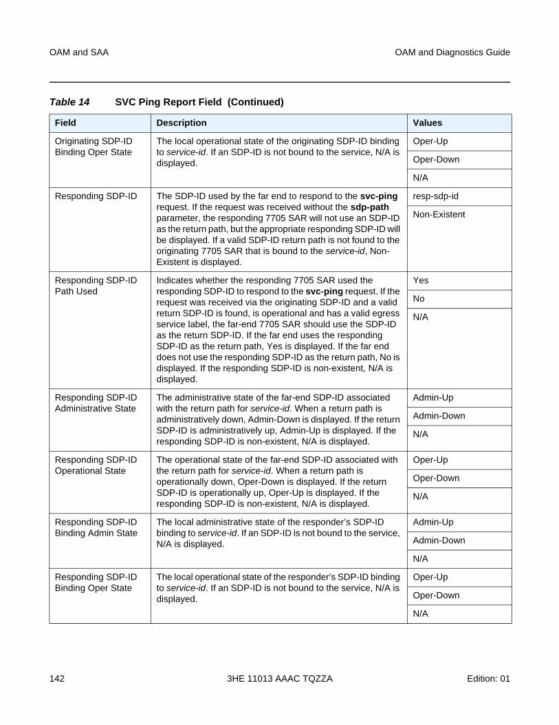
OAM and SAA
142
OAM and Diagnostics Guide
3HE 11013 AAAC TQZZA Edition: 01
Originating SDP-ID Binding Oper State
The local operational state of the originating SDP-ID binding to service-id. If an SDP-ID is not bound to the service, N/A is displayed.
Oper-Up
Oper-Down
N/A
Responding SDP-ID The SDP-ID used by the far end to respond to the svc-ping request. If the request was received without the sdp-path parameter, the responding 7705 SAR will not use an SDP-ID as the return path, but the appropriate responding SDP-ID will be displayed. If a valid SDP-ID return path is not found to the originating 7705 SAR that is bound to the service-id, Non-Existent is displayed.
resp-sdp-id
Non-Existent
Responding SDP-ID Path Used
Indicates whether the responding 7705 SAR used the responding SDP-ID to respond to the svc-ping request. If the request was received via the originating SDP-ID and a valid return SDP-ID is found, is operational and has a valid egress service label, the far-end 7705 SAR should use the SDP-ID as the return SDP-ID. If the far end uses the responding SDP-ID as the return path, Yes is displayed. If the far end does not use the responding SDP-ID as the return path, No is displayed. If the responding SDP-ID is non-existent, N/A is displayed.
Yes
No
N/A
Responding SDP-ID Administrative State
The administrative state of the far-end SDP-ID associated with the return path for service-id. When a return path is administratively down, Admin-Down is displayed. If the return SDP-ID is administratively up, Admin-Up is displayed. If the responding SDP-ID is non-existent, N/A is displayed.
Admin-Up
Admin-Down
N/A
Responding SDP-ID Operational State
The operational state of the far-end SDP-ID associated with the return path for service-id. When a return path is operationally down, Oper-Down is displayed. If the return SDP-ID is operationally up, Oper-Up is displayed. If the responding SDP-ID is non-existent, N/A is displayed.
Oper-Up
Oper-Down
N/A
Responding SDP-ID Binding Admin State
The local administrative state of the responder’s SDP-ID binding to service-id. If an SDP-ID is not bound to the service, N/A is displayed.
Admin-Up
Admin-Down
N/A
Responding SDP-ID Binding Oper State
The local operational state of the responder’s SDP-ID binding to service-id. If an SDP-ID is not bound to the service, N/A is displayed.
Oper-Up
Oper-Down
N/A
Table 14 SVC Ping Report Field (Continued)
Field Description Values
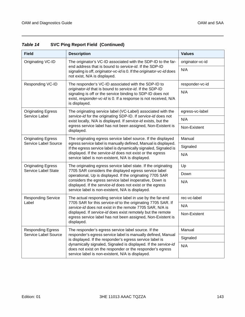
OAM and Diagnostics Guide OAM and SAA
Edition: 01 3HE 11013 AAAC TQZZA 143
Originating VC-ID The originator’s VC-ID associated with the SDP-ID to the far-end address that is bound to service-id. If the SDP-ID signaling is off, originator-vc-id is 0. If the originator-vc-id does not exist, N/A is displayed.
originator-vc-id
N/A
Responding VC-ID The responder’s VC-ID associated with the SDP-ID to originator-id that is bound to service-id. If the SDP-ID signaling is off or the service binding to SDP-ID does not exist, responder-vc-id is 0. If a response is not received, N/A is displayed.
responder-vc-id
N/A
Originating Egress Service Label
The originating service label (VC-Label) associated with the service-id for the originating SDP-ID. If service-id does not exist locally, N/A is displayed. If service-id exists, but the egress service label has not been assigned, Non-Existent is displayed.
egress-vc-label
N/A
Non-Existent
Originating Egress Service Label Source
The originating egress service label source. If the displayed egress service label is manually defined, Manual is displayed. If the egress service label is dynamically signaled, Signaled is displayed. If the service-id does not exist or the egress service label is non-existent, N/A is displayed.
Manual
Signaled
N/A
Originating Egress Service Label State
The originating egress service label state. If the originating 7705 SAR considers the displayed egress service label operational, Up is displayed. If the originating 7705 SAR considers the egress service label inoperative, Down is displayed. If the service-id does not exist or the egress service label is non-existent, N/A is displayed.
Up
Down
N/A
Responding Service Label
The actual responding service label in use by the far-end 7705 SAR for this service-id to the originating 7705 SAR. If service-id does not exist in the remote 7705 SAR, N/A is displayed. If service-id does exist remotely but the remote egress service label has not been assigned, Non-Existent is displayed.
rec-vc-label
N/A
Non-Existent
Responding Egress Service Label Source
The responder’s egress service label source. If the responder’s egress service label is manually defined, Manual is displayed. If the responder’s egress service label is dynamically signaled, Signaled is displayed. If the service-id does not exist on the responder or the responder’s egress service label is non-existent, N/A is displayed.
Manual
Signaled
N/A
Table 14 SVC Ping Report Field (Continued)
Field Description Values
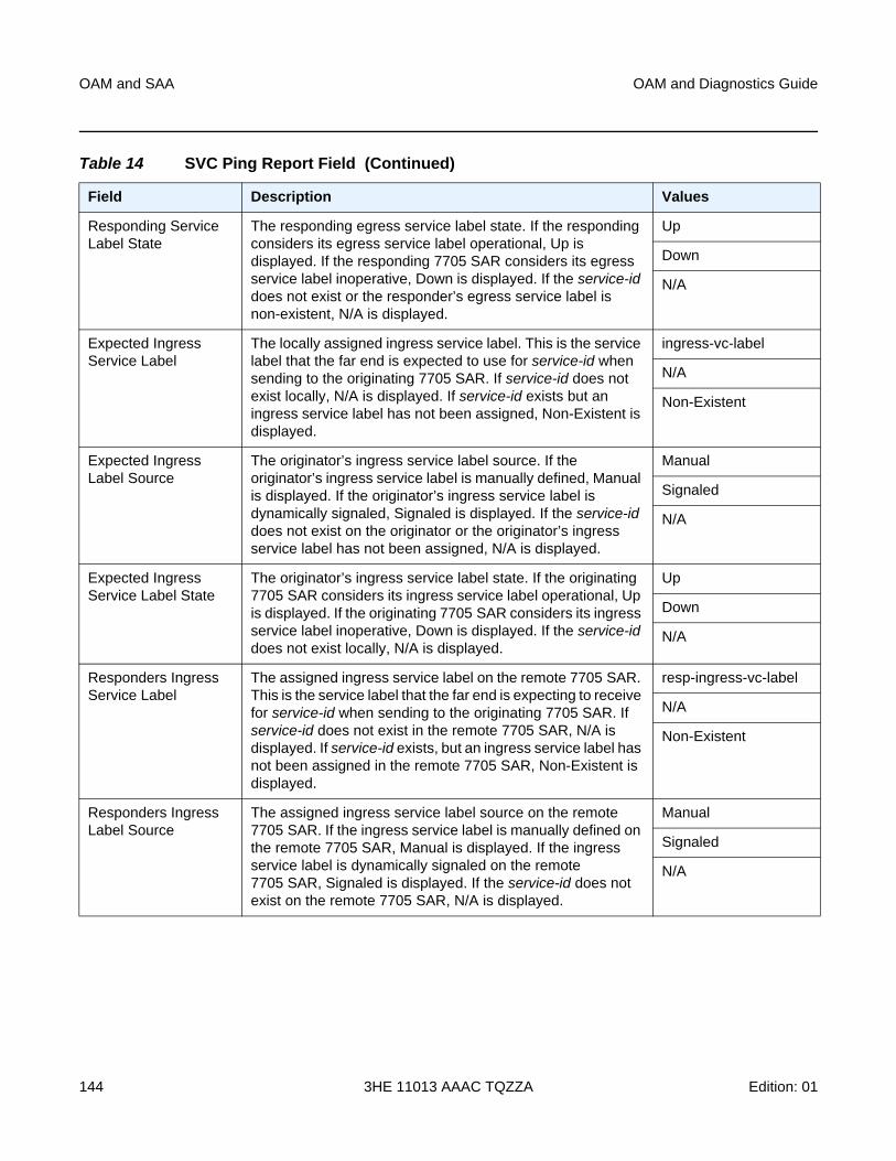
OAM and SAA
144
OAM and Diagnostics Guide
3HE 11013 AAAC TQZZA Edition: 01
Responding Service Label State
The responding egress service label state. If the responding considers its egress service label operational, Up is displayed. If the responding 7705 SAR considers its egress service label inoperative, Down is displayed. If the service-id does not exist or the responder’s egress service label is non-existent, N/A is displayed.
Up
Down
N/A
Expected Ingress Service Label
The locally assigned ingress service label. This is the service label that the far end is expected to use for service-id when sending to the originating 7705 SAR. If service-id does not exist locally, N/A is displayed. If service-id exists but an ingress service label has not been assigned, Non-Existent is displayed.
ingress-vc-label
N/A
Non-Existent
Expected Ingress Label Source
The originator’s ingress service label source. If the originator’s ingress service label is manually defined, Manual is displayed. If the originator’s ingress service label is dynamically signaled, Signaled is displayed. If the service-id does not exist on the originator or the originator’s ingress service label has not been assigned, N/A is displayed.
Manual
Signaled
N/A
Expected Ingress Service Label State
The originator’s ingress service label state. If the originating 7705 SAR considers its ingress service label operational, Up is displayed. If the originating 7705 SAR considers its ingress service label inoperative, Down is displayed. If the service-id does not exist locally, N/A is displayed.
Up
Down
N/A
Responders Ingress Service Label
The assigned ingress service label on the remote 7705 SAR. This is the service label that the far end is expecting to receive for service-id when sending to the originating 7705 SAR. If service-id does not exist in the remote 7705 SAR, N/A is displayed. If service-id exists, but an ingress service label has not been assigned in the remote 7705 SAR, Non-Existent is displayed.
resp-ingress-vc-label
N/A
Non-Existent
Responders Ingress Label Source
The assigned ingress service label source on the remote 7705 SAR. If the ingress service label is manually defined on the remote 7705 SAR, Manual is displayed. If the ingress service label is dynamically signaled on the remote 7705 SAR, Signaled is displayed. If the service-id does not exist on the remote 7705 SAR, N/A is displayed.
Manual
Signaled
N/A
Table 14 SVC Ping Report Field (Continued)
Field Description Values
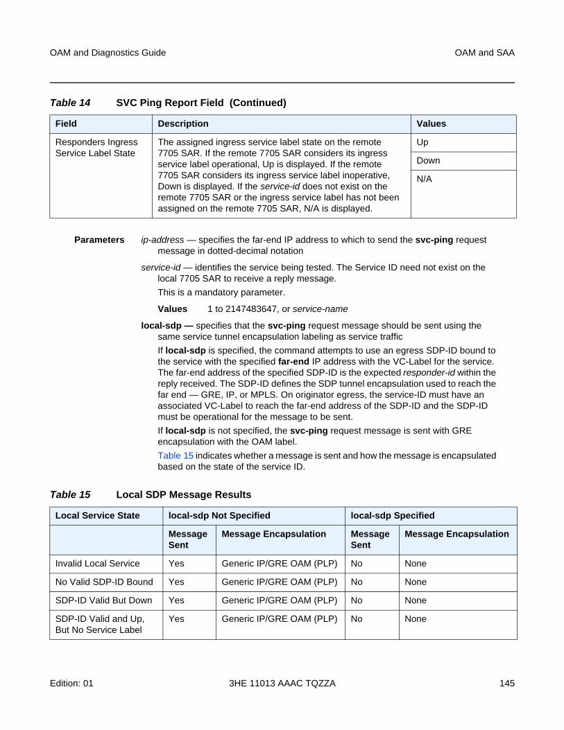
OAM and Diagnostics Guide OAM and SAA
Edition: 01 3HE 11013 AAAC TQZZA 145
Parameters ip-address — specifies the far-end IP address to which to send the svc-ping request message in dotted-decimal notation
service-id — identifies the service being tested. The Service ID need not exist on the local 7705 SAR to receive a reply message.
This is a mandatory parameter.
Values 1 to 2147483647, or service-name
local-sdp — specifies that the svc-ping request message should be sent using the same service tunnel encapsulation labeling as service traffic
If local-sdp is specified, the command attempts to use an egress SDP-ID bound to the service with the specified far-end IP address with the VC-Label for the service. The far-end address of the specified SDP-ID is the expected responder-id within the reply received. The SDP-ID defines the SDP tunnel encapsulation used to reach the far end — GRE, IP, or MPLS. On originator egress, the service-ID must have an associated VC-Label to reach the far-end address of the SDP-ID and the SDP-ID must be operational for the message to be sent.
If local-sdp is not specified, the svc-ping request message is sent with GRE encapsulation with the OAM label.
Table 15 indicates whether a message is sent and how the message is encapsulated based on the state of the service ID.
Responders Ingress Service Label State
The assigned ingress service label state on the remote 7705 SAR. If the remote 7705 SAR considers its ingress service label operational, Up is displayed. If the remote 7705 SAR considers its ingress service label inoperative, Down is displayed. If the service-id does not exist on the remote 7705 SAR or the ingress service label has not been assigned on the remote 7705 SAR, N/A is displayed.
Up
Down
N/A
Table 14 SVC Ping Report Field (Continued)
Field Description Values
Table 15 Local SDP Message Results
Local Service State local-sdp Not Specified local-sdp Specified
Message Sent
Message Encapsulation Message Sent
Message Encapsulation
Invalid Local Service Yes Generic IP/GRE OAM (PLP) No None
No Valid SDP-ID Bound Yes Generic IP/GRE OAM (PLP) No None
SDP-ID Valid But Down Yes Generic IP/GRE OAM (PLP) No None
SDP-ID Valid and Up, But No Service Label
Yes Generic IP/GRE OAM (PLP) No None
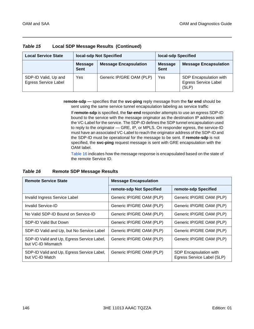
OAM and SAA
146
OAM and Diagnostics Guide
3HE 11013 AAAC TQZZA Edition: 01
remote-sdp — specifies that the svc-ping reply message from the far end should be sent using the same service tunnel encapsulation labeling as service traffic
If remote-sdp is specified, the far-end responder attempts to use an egress SDP-ID bound to the service with the message originator as the destination IP address with the VC-Label for the service. The SDP-ID defines the SDP tunnel encapsulation used to reply to the originator — GRE, IP, or MPLS. On responder egress, the service-ID must have an associated VC-Label to reach the originator address of the SDP-ID and the SDP-ID must be operational for the message to be sent. If remote-sdp is not specified, the svc-ping request message is sent with GRE encapsulation with the OAM label.
Table 16 indicates how the message response is encapsulated based on the state of the remote Service ID.
SDP-ID Valid, Up and Egress Service Label
Yes Generic IP/GRE OAM (PLP) Yes SDP Encapsulation with Egress Service Label (SLP)
Table 15 Local SDP Message Results (Continued)
Local Service State local-sdp Not Specified local-sdp Specified
Message Sent
Message Encapsulation Message Sent
Message Encapsulation
Table 16 Remote SDP Message Results
Remote Service State Message Encapsulation
remote-sdp Not Specified remote-sdp Specified
Invalid Ingress Service Label Generic IP/GRE OAM (PLP) Generic IP/GRE OAM (PLP)
Invalid Service-ID Generic IP/GRE OAM (PLP) Generic IP/GRE OAM (PLP)
No Valid SDP-ID Bound on Service-ID Generic IP/GRE OAM (PLP) Generic IP/GRE OAM (PLP)
SDP-ID Valid But Down Generic IP/GRE OAM (PLP) Generic IP/GRE OAM (PLP)
SDP-ID Valid and Up, but No Service Label Generic IP/GRE OAM (PLP) Generic IP/GRE OAM (PLP)
SDP-ID Valid and Up, Egress Service Label, but VC-ID Mismatch
Generic IP/GRE OAM (PLP) Generic IP/GRE OAM (PLP)
SDP-ID Valid and Up, Egress Service Label, but VC-ID Match
Generic IP/GRE OAM (PLP) SDP Encapsulation with Egress Service Label (SLP)
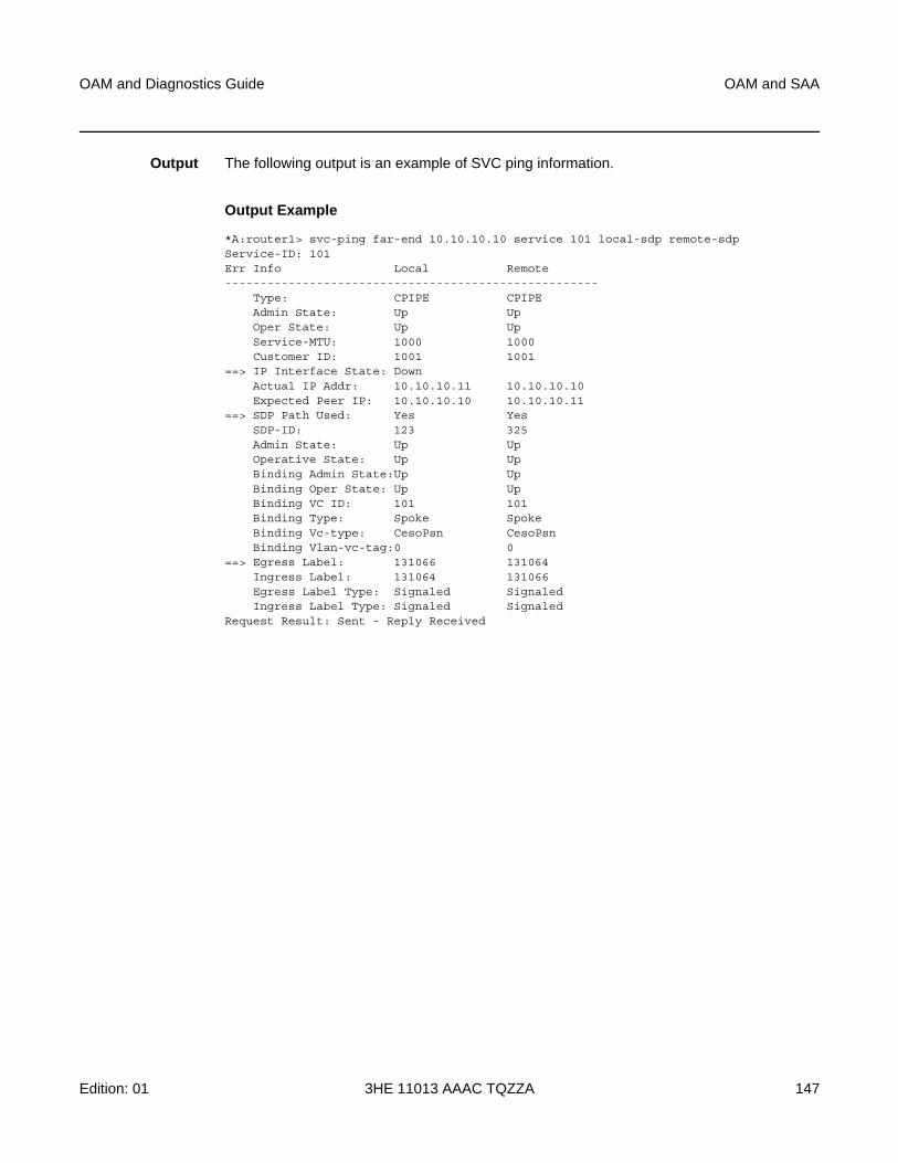
OAM and Diagnostics Guide OAM and SAA
Edition: 01 3HE 11013 AAAC TQZZA 147
Output The following output is an example of SVC ping information.
Output Example
*A:router1> svc-ping far-end 10.10.10.10 service 101 local-sdp remote-sdpService-ID: 101Err Info Local Remote-----------------------------------------------------
Type: CPIPE CPIPEAdmin State: Up UpOper State: Up UpService-MTU: 1000 1000Customer ID: 1001 1001
==> IP Interface State: DownActual IP Addr: 10.10.10.11 10.10.10.10Expected Peer IP: 10.10.10.10 10.10.10.11
==> SDP Path Used: Yes YesSDP-ID: 123 325Admin State: Up UpOperative State: Up UpBinding Admin State:Up UpBinding Oper State: Up UpBinding VC ID: 101 101Binding Type: Spoke SpokeBinding Vc-type: CesoPsn CesoPsnBinding Vlan-vc-tag:0 0
==> Egress Label: 131066 131064Ingress Label: 131064 131066Egress Label Type: Signaled SignaledIngress Label Type: Signaled Signaled
Request Result: Sent - Reply Received
OAM and SAA
148
OAM and Diagnostics Guide
3HE 11013 AAAC TQZZA Edition: 01
3.6.2.1.5 EFM Commands
efm
Syntax efm port-id
Context oam
Description This command enables Ethernet in the First Mile (EFM) OAM loopbacks on the specified port. The EFM OAM remote loopback OAMPDU will be sent to the peering device to trigger a remote loopback.
Parameters port-id — specifies the port ID in the slot/mda/port format
local-loopback
Syntax local-loopback {start | stop}
Context oam>efm
Description This command enables local loopback tests on the specified port.
remote-loopback
Syntax remote-loopback {start | stop}
Context oam>efm
Description This command enables remote EFM OAM loopback tests on the specified port. The EFM OAM remote loopback OAMPDU will be sent to the peering device to trigger a remote loopback.
ethernet
Syntax ethernet
Context config>port
Description This command enables access to the context to configure Ethernet port attributes.
OAM and Diagnostics Guide OAM and SAA
Edition: 01 3HE 11013 AAAC TQZZA 149
efm-oam
Syntax efm-oam
Context config>port>ethernet
Description This command configures EFM OAM attributes.
accept-remote-loopback
Syntax [no] accept-remote-loopback
Context config>port>ethernet>efm-oam
Description This command enables reactions to loopback control OAMPDUs from peers.
The no form of this command disables reactions to loopback control OAMPDUs.
hold-time
Syntax hold-time time-value
no hold-time
Context config>port>ethernet>efm-oam
Description This command sets the amount of time that EFM-OAM will wait before going from a non-operational state to an operational state.
If EFM-OAM goes from an operational state to a non-operational state (other than link-fault), it enters the hold-time period. During this time, EFM-OAM continues to negotiate with the peer if possible, but will not transition to the “up” state until the hold time has expired.
If EFM-OAM goes down due to a lower-level fault (for example, the port goes down and EFM-OAM enters the link-fault state), the hold timer is not triggered. When the lower-level fault is cleared, EFM-OAM immediately starts running on the port and transitions to the operational state as soon as possible.
If EFM-OAM goes down because the user administratively disables the protocol, EFM-OAM immediately transitions to the disabled state. When the user re-enables EFM-OAM, the protocol enters the hold time period and EFM-OAM is not operational until the hold time expires. A hold-time value of 0 indicates that EFM-OAM returns to the operational state without delay.
The hold time affects only the transition from a non-operational state to an operational state; it does not apply to a transition from an operational state to a non-operational state.
OAM and SAA
150
OAM and Diagnostics Guide
3HE 11013 AAAC TQZZA Edition: 01
Parameters time-value — the number of seconds that EFM-OAM will wait before returning to an operational state from a non-operational state
Values 0 to 50
Default 0
mode
Syntax mode {active | passive}
Context config>port>ethernet>efm-oam
Description This command configures the mode of OAM operation for this Ethernet port.
Active mode causes the port to initiate the negotiation process and continually send out EFM OAM information PDUs. Passive mode waits for the peer to initiate the negotiation process. A passive mode port cannot initiate monitoring activities (such as loopback) with the peer.
Default active
transmit-interval
Syntax [no] transmit-interval interval [multiplier multiplier]
Context config>port>ethernet>efm-oam
Description This command configures the transmit interval of OAMPDUs.
Parameters interval — specifies the transmit interval
Values 1 to 600 (in 100 ms)
multiplier — specifies the multiplier for the transmit interval to set the local link down timer
Values 2 to 5
tunneling
Syntax [no] tunneling
Context config>port>ethernet>efm-oam
Description This command enables EFM OAMPDU tunneling. OAMPDU tunneling is required when a loopback is initiated from a router end and must be transported over the existing network infrastructure to the other end. Enabling tunneling will allow the PDUs to be mapped to Epipes so that the OAM frames can be tunneled over MPLS to the far end. To enable Ethernet EFM OAM 802.3ah on the port, use the efm-oam>no shutdown command. The no form of the command disables tunneling.
OAM and Diagnostics Guide OAM and SAA
Edition: 01 3HE 11013 AAAC TQZZA 151
3.6.2.1.6 ETH-CFM Commands
eth-test
Syntax eth-test mac-address mep mep-id domain md-index association ma-index [priority priority] [data-length data-length]
Context oam>eth-cfm
Description This command specifies to initiate an Ethernet (signal) test.
Parameters mac-address — specifies a unicast MAC address
Values xx:xx:xx:xx:xx:xx or xx-xx-xx-xx-xx-xx, where xx is a hexadecimal number
mep-id — specifies the target MEP ID
Values 1 to 8191
md-index — specifies the MD index
Values 1 to 4294967295
priority — specifies the value used for priority mapping. Refer to Table 6 to determine how the priority is derived; if it is user-defined, then refer to Table 5 for the priority-to-FC mappings.
Values 0 to 7
Default the CCM and LTM priority of the MEP
ma-index — specifies the MA index
Values 1 to 4294967295
data-length — specifies the packet size in bytes, expressed as a decimal integer, used for the ETH-CFM test
Values 64 to 1500
Default 64
linktrace
Syntax linktrace mac-address mep mep-id domain md-index association ma-index [ttl ttl-value]
Context oam>eth-cfm
Description This command specifies to initiate a linktrace test.
OAM and SAA
152
OAM and Diagnostics Guide
3HE 11013 AAAC TQZZA Edition: 01
Parameters mac-address — specifies a unicast destination MAC address
Values xx:xx:xx:xx:xx:xx or xx-xx-xx-xx-xx-xx, where xx is a hexadecimal number
mep-id — specifies the target MEP ID
Values 1 to 8191
md-index — specifies the MD index
Values 1 to 4294967295
ma-index — specifies the MA index
Values 1 to 4294967295
ttl-value — specifies the TTL for a returned linktrace
Values 0 to 255
loopback
Syntax loopback mac-address mep mep-id domain md-index association ma-index [send-count send-count] [size data-size] [priority priority]
Context oam>eth-cfm
Description This command specifies to initiate a loopback test.
Parameters mac-address — specifies a unicast MAC address
Values xx:xx:xx:xx:xx:xx or xx-xx-xx-xx-xx-xx, where xx is a hexadecimal number
mep-id — specifies the target MEP ID
Values 1 to 8191
md-index — specifies the MD index
Values 1 to 4294967295
ma-index — specifies the MA index
Values 1 to 4294967295
send-count — specifies the number of messages to send, expressed as a decimal integer. Dot1ag loopback messages are sent back-to-back, with no delay between the transmissions.
Values 1 to 5
Default 1
OAM and Diagnostics Guide OAM and SAA
Edition: 01 3HE 11013 AAAC TQZZA 153
data-size — specifies the packet size in bytes, expressed as a decimal integer
Values 0 to 1500
Default 0
priority — specifies the value used for priority mapping. Refer to Table 6 to determine how the priority is derived; if it is user-defined, then refer to Table 5 for the priority-to-FC mappings.
Values 0 to 7
Default the CCM and LTM priority of the MEP
one-way-delay-test
Syntax one-way-delay-test mac-address mep mep-id domain md-index association ma-index [priority priority]
Context oam>eth-cfm
Description This command specifies to initiate an ETH-CFM one-way delay test.
Parameters mac-address — specifies a unicast MAC address
Values xx:xx:xx:xx:xx:xx or xx-xx-xx-xx-xx-xx, where xx is a hexadecimal number
mep-id — specifies the target MEP ID
Values 1 to 8191
md-index — specifies the MD index
Values 1 to 4294967295
ma-index — specifies the MA index
Values 1 to 4294967295
priority — specifies the value used for priority mapping. Refer to Table 6 to determine how the priority is derived; if it is user-defined, then refer to Table 5 for the priority-to-FC mappings.
Values 0 to 7
Default The CCM and LTM priority of the MEP
two-way-delay-test
Syntax two-way-delay-test mac-address mep mep-id domain md-index association ma-index [priority priority]
Context oam>eth-cfm
OAM and SAA
154
OAM and Diagnostics Guide
3HE 11013 AAAC TQZZA Edition: 01
Description This command specifies to initiate an ETH-CFM two-way delay test.
Parameters mac-address — specifies a unicast MAC address
Values xx:xx:xx:xx:xx:xx or xx-xx-xx-xx-xx-xx, where xx is a hexadecimal number
mep-id — specifies the target MEP ID
Values 1 to 8191
md-index — specifies the MD index
Values 1 to 4294967295
ma-index — specifies the MA index
Values 1 to 4294967295
priority — specifies the value used for priority mapping. Refer to Table 6 to determine how the priority is derived; if it is user-defined, then refer to Table 5 for the priority-to-FC mappings.
Values 0 to 7
Default The CCM and LTM priority of the MEP
two-way-slm-test
Syntax two-way-slm-test mac-address mep mep-id domain md-index association ma-index [priority priority] [send-count send-count] [size data-size] [timeout timeout] [interval interval]
Context oam>eth-cfm
Description This command specifies to initiate an Ethernet CFM two-way SLM test.
Parameters mac-address — specifies a unicast MAC address
Values xx:xx:xx:xx:xx:xx or xx-xx-xx-xx-xx-xx, where xx is a hexadecimal number
mep-id — specifies the target MEP ID
Values 1 to 8191
md-index — specifies the MD index
Values 1 to 4294967295
ma-index — specifies the MA index
Values 1 to 4294967295
OAM and Diagnostics Guide OAM and SAA
Edition: 01 3HE 11013 AAAC TQZZA 155
priority — specifies the value used for priority mapping. Refer to Table 6 to determine how the priority is derived; if it is user-defined, then refer to Table 5 for the priority-to-FC mappings.
Values 0 to 7
Default 7
send-count — the number of messages to send, expressed as a decimal integer. The message interval value must be expired before the next message request is sent.
Values 1 to 1000
Default 1
data-size — the size of the data portion of the data TLV. If 0 is specified, no data TLV is added to the packet.
Values 0 to 1500
Default 0
timeout — the timeout parameter in seconds. This value is the length of time that the router will wait for a message reply after sending the message request. If the timeout expires, the requesting router assumes that the message response will not be received. Any response received after the request times out will be silently discarded. The timeout value must be less than or equal to the interval.
Values 1 to 10
Default 5
interval — the time, in seconds between probes within a test run
Values 1 to 10
Default 5
single-ended-loss-test
Syntax single-ended-loss-test mac-address mep mep-id domain md-index association ma-index [priority priority] [interval {100ms | 1s}] [send-count send-count]
Context oam>eth-cfm
Description This command specifies to initiate a loss measurement test between the specified mac-address router and the specified mep-id MEP.
Single-ended and dual-ended loss tests are mutually exclusive tests. Single-ended loss tests can be run when dual-ended loss tests are disabled (under the config>service>epipe>spoke-sdp>eth-cfm>mep or config>router>if>eth-cfm>mep context).
OAM and SAA
156
OAM and Diagnostics Guide
3HE 11013 AAAC TQZZA Edition: 01
Parameters mac-address — specifies a unicast MAC address
Values xx:xx:xx:xx:xx:xx or xx-xx-xx-xx-xx-xx, where xx is a hexadecimal number
mep-id — specifies the target MEP ID
Values 1 to 8191
md-index — specifies the index of the MD to which the MEP is associated, or 0, if none
Values 1 to 4294967295
ma-index — specifies the index to which the MEP is associated, or 0, if none
Values 1 to 4294967295
send-count — specifies the number of LMM messages to send, expressed as a decimal integer
Values 2 to 5
Default 2
interval {100ms | 1s} — specifies the interval between groups of consecutive LMM packets (for example, if send-count is 5 and interval is 1s, then 5 LMM packets are sent at 1-s intervals)
Values 100ms | 1s
Default 1s
priority — specifies the value used for priority mapping. Refer to Table 6 to determine how the priority is derived; if it is user-defined, then refer to Table 5 for the priority-to-FC mappings.
Values 0 to 7
Default the CCM and LTM priority of the MEP
eth-cfm
Syntax eth-cfm
Context configconfig>service>epipe>sapconfig>service>epipe>spoke-sdpconfig>router>interface
Description This command enables the context to configure 802.1ag Connectivity Fault Management (CFM) parameters.
OAM and Diagnostics Guide OAM and SAA
Edition: 01 3HE 11013 AAAC TQZZA 157
domain
Syntax domain md-index [format {dns | mac | none | string}] [name md-name] level level
domain md-index
no domain md-index
Context config>eth-cfm
Description This command configures CFM domain parameters.
The dns, mac, and string keywords apply to dot1ag. The none keyword applies to Y.1731. If the none keyword is used, the association command must use the icc-based or string format. A MEP associated with domain format none and association format icc-based is a Y.1731 MEP. A MEP associated with domain format none and association format string is a Y.1731 MEP that can interoperate with a dot1ag MEP. All other configurations are associated with dot1ag MEPs.
The no form of the command removes the MD index parameters from the configuration.
Parameters md-index — specifies the Maintenance Domain (MD) index value
Values 1 to 4294967295
format {dns | mac | none | string} — specifies a value that represents the type (format) of the md-name
Values dns: specifies the DNS name format
mac: X:X:X:X:X:X-u
X: [0 to FF] hex
u: [0 to 65535] decimal
none: no name specified (the domain represents a Y.1731 MEG, not a dot1ag domain)
string: specifies an ASCII string
Default string
md-name — specifies a generic Maintenance Domain (MD) name
Values 1 to 43 characters
level — specifies the integer identifying the maintenance domain level (MD level). Higher numbers correspond to higher-level maintenance domains (those with the greatest physical reach) with the highest values for customers’ CFM packets. Lower numbers correspond to lower-level maintenance domains (those with more limited physical reach) with the lowest values for single bridges or physical links.
Values 0 to 7
OAM and SAA
158
OAM and Diagnostics Guide
3HE 11013 AAAC TQZZA Edition: 01
association
Syntax association ma-index [format {icc-based | integer | string | vid | vpn-id}] name ma-name
association ma-index
no association ma-index
Context config>eth-cfm>domain
Description This command configures the Maintenance Association (MA) for the domain.
The integer, string, vid, and vpn-id keywords apply to dot1ag MAs. The icc-based keyword applies to Y.1731 MEGs, and is only available when the domain format is none. A MEP associated with domain format none and association format icc-based is a Y.1731 MEP. A MEP associated with domain format none and association format string is a Y.1731 MEP that can interoperate with a dot1ag MEP. All other configurations are associated with dot1ag MEPs.
Parameters ma-index — specifies the MA index value
Values 1 to 4294967295
format {icc-based | integer | string | vid | vpn-id} — specifies a value that represents the type (format) of the ma-name
Values icc-based: raw ASCII, exactly 13 characters (the association is a Y.1731 MEG, not a dot1ag MA)
integer: 0 to 65535 (integer value 0 means the MA is not attached to a VID)
string: raw ASCII
vid: 0 to 4094
vpn-id: RFC 2685, Virtual Private Networks Identifier
xxx:xxxx where x is a value between 00 and FF (for example 00164D:AABBCCDD)
Default integer
ma-name — specifies the part of the maintenance association identifier that is unique within the maintenance domain name
Values 1 to 45 characters
bridge-identifier
Syntax [no] bridge-identifier bridge-id
Context config>eth-cfm>domain>association

OAM and Diagnostics Guide OAM and SAA
Edition: 01 3HE 11013 AAAC TQZZA 159
Description This command configures the service ID for the domain association. The bridge-id should be configured to match the service-id of the service where MEPs for this association will be created. For example, for Epipe service-id 2, set the bridge-id to 2. There is no verification that the service with a matching service-id exists.
This command does not apply to facility MEPs on network interfaces, as these MEPs are not bound to a service.
Parameters bridge-id — specifies the bridge ID for the domain association
Values 1 to 2147483647
vlan
Syntax vlan vlan-id
no vlan
Context config>eth-cfm>domain>association>bridge-identifier
Description This command configures the bridge-identifier primary VLAN ID. This command is informational only; no verification is done to ensure that MEPs on this association are on the configured VLAN.
Parameters vlan-id — specifies a VLAN ID monitored by MA.
Values 0 to 4094
ccm-interval
Syntax ccm-interval {10ms | 100ms | 1 | 10 | 60 | 600}
no ccm-interval
Context config>eth-cfm>domain>association
Description This command configures the CCM transmission interval for all MEPs in the association, in milliseconds and seconds.
The no form of the command reverts to the default value.
Default 10 s
remote-mepid
Syntax [no] remote-mepid mep-id
Context config>eth-cfm>domain>association
Description This command configures the remote maintenance association endpoint MEP identifier.
OAM and SAA
160
OAM and Diagnostics Guide
3HE 11013 AAAC TQZZA Edition: 01
Parameters mep-id — maintenance association endpoint identifier of a remote MEP whose information from the MEP database is to be returned
Values 1 to 8191
slm
Syntax slm
Context config>eth-cfm
Description This command enables the context to configure ITU-T Synthetic Loss Measurement (ETH-SL).
inactivity-timer
Syntax inactivity-timer timeout
no inactivity-timer
Context config>eth-cfm>slm
Description This command configures the time that the responder keeps a test active. If the time between packets exceeds this value within a test, the responder marks the previous test as complete. It treats any new packets from a peer with the same test-id, source MAC address, and MEP-ID as a new test, and indicates this by responding with the sequence number 1.
Default 100 s
Parameters timeout — specifies the inactivity timeout value, in seconds
Values 10 to 100
Default 100
cfm-loopback
Syntax cfm-loopback priority {low | high | dot1p} [match-vlan {vlan-range | none}]
no cfm-loopback
Context config>port>ethernetconfig>port>dslconfig>port>gpon
Description This command enables the port to respond to LBM messages and sets the queuing and scheduling conditions for handling CFM LBM frames. The user selects the desired QoS treatment by enabling the CFM loopback and including the high or low priority with the high or low keyword. The queue parameters and scheduler mappings associated with the high and low keywords are preconfigured and cannot be altered by the user.
OAM and Diagnostics Guide OAM and SAA
Edition: 01 3HE 11013 AAAC TQZZA 161
The priority dot1p and match-vlan keywords apply only to physical ring ports on the 2-port 10GigE (Ethernet) Adapter card/module.
The parameters and mappings have the following settings:
• for network egress, where profiled scheduling is the choice of scheduling:
− high-priority: either cir = port_speed, which applies to all frames that are scheduled via an in-profile scheduler, or round-robin (RR) for all other (network egress queue) frames that are in-profile
− low-priority: either cir = 0, pir = port_speed, which applies to all frames that are scheduled as out-of-profile, or RR for all other frames that are out-of-profile
• for network egress or access egress, where 4-priority scheduling is enabled:
− high-priority: either cir = port_speed, which applies to all frames that are scheduled via an expedited in-profile scheduler, or RR for all other (network egress queue) frames that reside in expedited queues and are in an in-profile state
− low-priority: either cir = 0, pir = port_speed, which applies to all frames that are scheduled via a best effort out-of-profile scheduler, or RR for all other frames that reside in best-effort queues and are in an out-of-profile state
• for the 6-port Ethernet 10Gbps Adapter card, the 8-port Gigabit Ethernet Adapter card, the 10-port 1GigE/1-port 10GigE X-Adapter card, and the v-port on the 2-port 10GigE (Ethernet) Adapter card/module, for network egress, where 16-priority scheduling is enabled:
− high-priority: has higher priority than any user frames
− low-priority: has lower priority than any user frames
• for the physical ring ports on the 2-port 10GigE (Ethernet) Adapter card/module, which can only operate as network egress, the priority of the LBR frame is derived from the dot1p setting of the received LBM frame. Based on the assigned ring-type network queue policy, dot1p-to-queue mapping is handled using the same mapping rule that applies to all other user frames.
CFM loopback support on a physical ring port on the 2-port 10GigE (Ethernet) Adapter card/module differs from other Ethernet ports. For these ports, cfm-loopback is configured using dot1p and an optional list of up to 16 VLANs. The null VLAN is always applied. The CFM Loopback Message will be processed if it does not contain a VLAN header, or if it contains a VLAN header with a VLAN ID that matches one in the configured match-vlan list.
The no form of the command disables the handling of CFM loopback frames.
Default no cfm-loopback
Parameters low — sets the queue parameters and scheduler mappings, as described above
high — sets the queue parameters and scheduler mappings, as described above
dot1p — sets the queue parameters and scheduler mappings on a physical ring port, as described above
OAM and SAA
162
OAM and Diagnostics Guide
3HE 11013 AAAC TQZZA Edition: 01
match-vlan — sets the matching VLAN IDs that will allow a CFM loopback on a physical ring port when priority is set to dot1p, as described above
Values vlan-range: 1 to 4094 (for example, 1-10,33,2123)
none: only untagged CFM Loopback messages are accepted
Default none
hold-mep-up-on-failure
Syntax [no] hold-mep-up-on-failure
Context config>service>epipe>sap>eth-cfm
Description This command keeps an 802.1ag or Y.1731 maintenance association endpoint (MEP) in operation regardless of the operational state of the SAP. The MEP remains in operation when the SAP is down or non-operational.
The no form of the command disables the MEP from remaining in operation when the SAP is down or non-operational.
Default enabled
mep
Syntax mep mep-id domain md-index association ma-index [direction {up | down}]
no mep mep-id domain md-index association ma-index
Context config>service>epipe>sap>eth-cfmconfig>service>epipe>spoke-sdp>eth-cfmconfig>router>if>eth-cfm
Description This command provisions an 802.1ag or a Y.1731 maintenance association endpoint (MEP).
The 7705 SAR supports Up and Down MEPs on Ethernet SAPs (802.1ag and Y.1731), Down MEPs on Ethernet spoke SDPs (802.1ag only), and facility MEPs on network interfaces (802.1ag and Y.1731).
The no form of the command reverts to the default values.
Parameters mep-id — specifies the maintenance association endpoint identifier
Values 1 to 81921
md-index — specifies the maintenance domain (MD) index value
Values 1 to 4294967295
ma-index — specifies the MA index value
Values 1 to 4294967295
OAM and Diagnostics Guide OAM and SAA
Edition: 01 3HE 11013 AAAC TQZZA 163
up | down — specifies the direction in which the maintenance association (MEP) faces on the bridge port (up sends Continuity Check messages (CCMs) towards the fabric, down sends CCMs towards the egress port or line). The direction parameter is not supported on network interfaces.
ais-enable
Syntax [no] ais-enable
Context config>service>epipe>sap>eth-cfm>mep
Description This command enables the generation and the reception of AIS messages and applies to Y.1731 SAP MEPs only.
Default disabled
client-meg-level
Syntax client-meg-level [level [level ...]]
no client-meg-level
Context config>service>epipe>sap>eth-cfm>mep>ais-enable
Description This command configures the client Maintenance Entity Group (MEG) levels to use for AIS message generation. Up to seven levels can be provisioned, with the restriction that the client (remote) MEG level must be higher than the local MEG level.
Parameters level — specifies the client MEG level
Values 1 to 7
Default 1
interval
Syntax interval {1 | 60}
no interval
Context config>service>epipe>sap>eth-cfm>mep>ais-enable
Description This command specifies the transmission interval of AIS messages in seconds.
Parameters 1 | 60 — the transmission interval of AIS messages in seconds
Default 1
OAM and SAA
164
OAM and Diagnostics Guide
3HE 11013 AAAC TQZZA Edition: 01
priority
Syntax priority priority-value
no priority
Context config>service>epipe>sap>eth-cfm>mep>ais-enable
Description This command specifies the priority of AIS messages originated by the MEP, which is used for priority-mapping OAM frames.
Parameters priority-value — specifies the priority value of the AIS messages originated by the node
Values 0 to 7
Default 7
ccm-enable
Syntax [no] ccm-enable
Context config>service>epipe>sap>eth-cfm>mepconfig>service>epipe>spoke-sdp>eth-cfm>mepconfig>router>if>eth-cfm>mep
Description This command enables the generation of CCM messages.
The no form of the command disables the generation of CCM messages.
ccm-ltm-priority
Syntax ccm-ltm-priority priority
no ccm-ltm-priority
Context config>service>epipe>sap>eth-cfm>mepconfig>service>epipe>spoke-sdp>eth-cfm>mepconfig>router>if>eth-cfm>mep
Description This command specifies the priority value for Continuity Check messages (CCMs) and linktrace messages (LTMs) transmitted by the MEP.
The default priority is 7, which means that CCM frames map to the NC forwarding class by default.
The no form of the command removes the priority value from the configuration.
Default 7
OAM and Diagnostics Guide OAM and SAA
Edition: 01 3HE 11013 AAAC TQZZA 165
Parameters priority — specifies the value used for priority mapping. Refer to Table 6 to determine how the priority is derived; if it is user-defined, then refer to Table 5 for the priority-to-FC mappings.
Values 0 to 7
ccm-tlv-ignore
Syntax ccm-tlv-ignore [port-status] [interface-status]
no ccm-tlv-ignore
Context config>router>if>eth-cfm>mep
Description This command allows the receiving MEP to ignore the specified TLVs in the ETH CCM PDU. Ignored TLVs will be reported as absent and will have no effect on the MEP.
The no form of the command causes the receiving MEP to process all recognized TLVs in the ETH CCM PDU.
Default n/a
Parameters port-status — ignore the port status TLV when it is received
interface-status — ignore the interface status TLV when it is received
description
Syntax description description-string
no description
Context config>service>epipe>sap>eth-cfm>mepconfig>service>epipe>spoke-sdp>eth-cfm>mepconfig>router>if>eth-cfm>mep
Description This command creates a text description of a MEP. The description can be changed at any time, even while the server is running.
The no form of the command removes the description.
Default no description
Parameters description-string — the description character string. Allowed values are any string up to 80 characters long composed of printable, 7-bit ASCII characters. If the string contains special characters (#, $, spaces, etc.), the entire string must be enclosed within double quotes.
OAM and SAA
166
OAM and Diagnostics Guide
3HE 11013 AAAC TQZZA Edition: 01
dual-ended-loss-test-enable
Syntax [no] dual-ended-loss-test-enable
Context config>service>epipe>sap>eth-cfm>mepconfig>service>epipe>spoke-sdp>eth-cfm>mepconfig>router>if>eth-cfm>mep
Description This command enables dual-ended loss measurement testing on a MEP. When enabled, the test runs in the background.
CCM must be enabled before the dual-ended loss measurement test can be enabled.
The dual-ended and single-ended loss measurement tests are mutually exclusive tests. When the dual-ended loss measurement test is enabled, the single-ended test is not available.
The no form of the command disables the dual-ended loss measurement test.
This command applies only to Y.1731 MEPs.
Default enabled
alarm-threshold
Syntax alarm-threshold percentage
no alarm-threshold
Context config>service>epipe>sap>eth-cfm>mep>dual-ended-loss-test-enableconfig>service>epipe>spoke-sdp>eth-cfm>mep>dual-ended-loss-test-enableconfig>router>if>eth-cfm>mep>dual-ended-loss-test-enable
Description This command specifies the alarm threshold ratio for frame loss measurement, where percentage is defined as (the total number of Tx frames) divided by (the total number of frames dropped) expressed as a percentage. When the alarm threshold is reached, an alarm is raised.
The no form of the command removes the priority value from the configuration. Setting the percentage to 0.00 is equivalent to using the no form of the command.
Parameters percentage — 0.00 to 100.00, adjustable in 0.01% increments
Default 0.25
alarm-clear-threshold
Syntax alarm-clear-threshold percentage
[no] alarm-clear-threshold
OAM and Diagnostics Guide OAM and SAA
Edition: 01 3HE 11013 AAAC TQZZA 167
Context config>service>epipe>sap>eth-cfm>mep>dual-ended-loss-test-enableconfig>router>if>eth-cfm>mep>dual-ended-loss-test-enable
Description This command configures a clearing alarm threshold for frame loss measurement, where percentage is defined as (the total number of Tx frames) divided by (the total number of frames dropped) expressed as a percentage.
If a dual-ended-loss alarm is outstanding and the alarm-clear-threshold is configured to a non-zero value, the dual-ended-loss clear alarm will not be raised until the dual-ended-loss ratio drops below the alarm-clear-threshold. If the alarm-clear-threshold is configured to 0, the dual-ended-loss clear alarm is raised immediately when the dual-ended-loss ratio drops below the alarm threshold.
This functionality prevents too many alarms from being generated if the loss ratio is toggling above and below the alarm threshold.
The alarm-clear-threshold cannot be greater than the alarm-threshold.
Setting the percentage to 0 means that no alarm-clear-threshold is configured; clear alarm traps will continue to be sent when the loss ratio is no longer above the alarm threshold. This is equivalent to using the no form of the command.
Parameters percentage — 0.00 to 100.00, adjustable in 0.01% increments
Default 0.00
eth-test-enable
Syntax [no] eth-test-enable
Context config>service>epipe>sap>eth-cfm>mepconfig>router>if>eth-cfm>mep
Description This command enables an Ethernet (signal) test (ETH-Test) on a MEP. When enabled, the test runs in the background. This command applies to Y.1731 MEPs only.
For this test, operators must configure ETH-Test parameters on both sender and receiver nodes. The ETH-Test can then be run using the following OAM command:
oam eth-cfm eth-test mac-address mep mep-id domain md-index association ma-index [priority priority] [data-length data-length]
A check is done on the provisioning and the test commands to ensure that the MEP is a Y.1731 MEP. If the MEP is not a Y.1731 MEP, the operation fails and an error message in the CLI and SNMP will indicate the problem. A Y.1731 MEP has domain format none and association format icc-based or string (the string keyword enables the Y.1731 MEP to interoperate with a dot1ag MEP).
The no form of the command disables the ETH-Test on a MEP.
Default enabled
OAM and SAA
168
OAM and Diagnostics Guide
3HE 11013 AAAC TQZZA Edition: 01
bit-error-threshold
Syntax bit-error-threshold bit-errors
Context config>service>epipe>sap>eth-cfm>mep>eth-test-enableconfig>router>if>eth-cfm>mep>eth-test-enable
Description This command configures a threshold for raising SNMP traps for one-way CFM tests.
For bit-error-threshold tests, test results are available only at the destination node. In order for the network management system to collect the results, SNMP traps need to be raised. This threshold is used to control when to raise a trap. When the number of bit errors reaches the threshold, an SNMP trap is raised.
Configuring a threshold value of 0 will cause the node to raise an SNMP trap for every one-way test it receives.
Parameters bit-errors — the bit-error threshold
Values 0 to 11840
Default 1
test-pattern
Syntax [no] test-pattern {all-zeros | all-ones} [crc-enable]
Context config>service>epipe>sap>eth-cfm>mep>eth-test-enableconfig>service>epipe>spoke-sdp>eth-cfm>mep>eth-test-enableconfig>router>if>eth-cfm>mep>eth-test-enable
Description This command configures the test pattern for ETH-Test frames.
The no form of the command removes the values from the configuration.
Parameters all-zeros | all-ones — specifies to use all zeros or all ones in the test pattern
Default all-zeros
crc-enable — specifies to generate a CRC checksum
low-priority-defect
Syntax low-priority-defect {allDef | macRemErrXcon | remErrXcon | errXcon | xcon | noXcon}
Context config>service>epipe>sap>eth-cfm>mepconfig>service>epipe>spoke-sdp>eth-cfm>mepconfig>router>if>eth-cfm>mep
Description This command specifies the lowest priority defect that is allowed to generate a fault alarm.
OAM and Diagnostics Guide OAM and SAA
Edition: 01 3HE 11013 AAAC TQZZA 169
Default remErrXcon
Parameters allDef — DefRDICCM, DefMACstatus, DefRemoteCCM, DefErrorCCM, and DefXconCCM
macRemErrXcon — DefMACstatus, DefRemoteCCM, DefErrorCCM, and DefXconCCM
remErrXcon — only DefRemoteCCM, DefErrorCCM, and DefXconCCM
errXcon — only DefErrorCCM and DefXconCCM
xcon — only DefXconCCM
noXcon — no defects DefXcon or lower are to be reported
one-way-delay-threshold
Syntax one-way-delay-threshold seconds
Context config>service>epipe>sap>eth-cfm>mepconfig>router>if>eth-cfm>mep
Description This command configures a threshold for raising SNMP traps for one-way CFM tests.
For one-way-delay-threshold tests, test results are available only at the destination node. In order for the network management system to collect the results, SNMP traps need to be raised. This threshold is used to control when to raise a trap. When the delay time reaches the threshold, an SNMP trap is raised.
Configuring a threshold value of 0 will cause the node to raise an SNMP trap for every one-way test it receives.
Parameters seconds — the delay time threshold value
Values 0 to 600
Default 3
OAM and SAA
170
OAM and Diagnostics Guide
3HE 11013 AAAC TQZZA Edition: 01
3.6.2.1.7 DSL Commands
dsl-f5-loopback
Syntax dsl-f5-loopback port-id
Context oam
Description This command enables the CPE-initiated F5 OAM loopback testing for an ATM bonding group on a DSL port.
After completing a loopback, you can run a show port command to see the results of the test.
Parameters port-id — specifies the physical port ID in the slot/mda/port format
OAM and Diagnostics Guide OAM and SAA
Edition: 01 3HE 11013 AAAC TQZZA 171
3.6.2.1.8 SAA Commands
saa
Syntax saa
Context config
Description This command enables the context to configure the SAA tests.
test
Syntax [no] test test-name [owner test-owner]
Context config>saa
Description This command identifies a test and creates or modifies the context to provide the test parameters for the named test. Subsequent to the creation of the test instance, the test can be started in the OAM context.
A test must be shut down before it can be modified or removed from the configuration.
The no form of this command removes the test from the configuration.
Parameters test-name — identifies the SAA test name to be created or edited
test-owner — specifies the owner of an SAA operation, up to 32 characters in length
Values if a test-owner value is not specified, tests created by the CLI have a default owner “TiMOS CLI”
accounting-policy
Syntax accounting-policy acct-policy-id ]
[no] accounting-policy ]
Context config>saa>test
Description This command associates an accounting policy to the SAA test. The accounting policy must already be defined before it can be associated or else an error message is generated.
A notification (trap) is issued when a test is completed.
The no form of this command removes the accounting policy association.
OAM and SAA
172
OAM and Diagnostics Guide
3HE 11013 AAAC TQZZA Edition: 01
Parameters acct-policy-id — specifies the accounting acct-policy-id as configured in the config>log>accounting-policy context
Values 1 to 99
description
Syntax description description-string
no description
Context config>saa>test
Description This command creates a text description stored in the configuration file for a configuration context.
The no form of this command removes the string from the configuration.
Default no description
Parameters description-string — the description character string. Allowed values are any string up to 80 characters long composed of printable, 7-bit ASCII characters. If the string contains special characters (#, $, spaces, etc.), the entire string must be enclosed within double quotes.
continuous
Syntax [no] continuous
Context config>saa>test
Description This command specifies whether the SAA test is continuous. Once you have configured a test as continuous, you cannot start or stop it by using the oam saa test-name {start | stop} command. This option is not applicable to all SAA test types.
The no form of the command disables the continuous execution of the test.
jitter-event
Syntax jitter-event rising-threshold threshold [falling-threshold threshold] [direction]
no jitter-event
Context config>saa>test
Description This command specifies that at the termination of an SAA test probe, the calculated jitter value is evaluated against the configured rising and falling jitter thresholds. SAA threshold events are generated as required.
OAM and Diagnostics Guide OAM and SAA
Edition: 01 3HE 11013 AAAC TQZZA 173
Once the threshold (rising/falling) is crossed, it is disabled from generating additional events until the opposite threshold is crossed. If a falling threshold is not supplied, the rising threshold will be re-enabled when it falls below the threshold after the initial crossing that generated the event.
The configuration of jitter event thresholds is optional.
Parameters rising-threshold threshold — specifies a rising threshold jitter value. When the test run is completed, the calculated jitter value is compared to the configured jitter rising threshold. If the test run jitter value is greater than the configured rising threshold value, then an SAA threshold event is generated. The SAA threshold event is tmnxOamSaaThreshold, logger application OAM, event #2101.
Values 0 to 2147483 ms
Default 0
falling-threshold threshold — specifies a falling threshold jitter value. When the test run is completed, the calculated jitter value is compared to the configured jitter falling threshold. If the test run jitter value is greater than the configured falling threshold value, then an SAA threshold event is generated. The SAA threshold event is tmnxOamSaaThreshold, logger application OAM, event #2101.
Values 0 to 2147483 ms
Default 0
direction — specifies the direction for OAM ping responses received for an OAM ping test run
Values inbound — monitors the jitter value calculated for the inbound, one-way, OAM ping responses received for an OAM ping test run
outbound — monitors the jitter value calculated for the outbound, one-way, OAM ping requests sent for an OAM ping test run
roundtrip — monitors the jitter value calculated for the round-trip, two-way, OAM ping requests and replies for an OAM ping test run
Default roundtrip
latency-event
Syntax latency-event rising-threshold threshold [falling-threshold threshold] [direction]
no latency-event
Context config>saa>test
Description This command specifies that at the termination of an SAA test probe, the calculated latency event value is evaluated against the configured rising and falling latency event thresholds. SAA threshold events are generated as required.
The configuration of latency event thresholds is optional.
OAM and SAA
174
OAM and Diagnostics Guide
3HE 11013 AAAC TQZZA Edition: 01
Parameters rising-threshold threshold — specifies a rising threshold latency value. When the test run is completed, the calculated latency value is compared to the configured latency rising threshold. If the test run latency value is greater than the configured rising threshold value, then an SAA threshold event is generated. The SAA threshold event is tmnxOamSaaThreshold, logger application OAM, event #2101.
Values 0 to 2147483647 ms
Default 0
falling-threshold threshold — specifies a falling threshold latency value. When the test run is completed, the calculated latency value is compared to the configured latency falling threshold. If the test run latency value is greater than the configured falling threshold value, then an SAA threshold event is generated. The SAA threshold event is tmnxOamSaaThreshold, logger application OAM, event #2101.
Values 0 to 2147483647 ms
Default 0
direction — specifies the direction for OAM ping responses received for an OAM ping test run
Values inbound — monitors the latency value calculated for the inbound, one-way, OAM ping responses received for an OAM ping test run
outbound — monitors the latency value calculated for the outbound, one-way, OAM ping requests sent for an OAM ping test run
roundtrip — monitors the latency value calculated for the round-trip, two-way, OAM ping requests and replies for an OAM ping test run
Default roundtrip
loss-event
Syntax loss-event rising-threshold threshold [falling-threshold threshold] [direction]
no loss-event
Context config>saa>test
Description This command specifies that at the termination of an SAA test run, the calculated loss event value is evaluated against the configured rising and falling loss event thresholds. SAA threshold events are generated as required.
The configuration of loss event thresholds is optional.
OAM and Diagnostics Guide OAM and SAA
Edition: 01 3HE 11013 AAAC TQZZA 175
Parameters rising-threshold threshold — specifies a rising threshold loss event value. When the test run is completed, the calculated loss event value is compared to the configured loss event rising threshold. If the test run loss event value is greater than the configured rising threshold value, then an SAA threshold event is generated. The SAA threshold event is tmnxOamSaaThreshold, logger application OAM, event #2101.
Values 0 to 2147483647 packets
Default 0
falling-threshold threshold — specifies a falling threshold loss event value. When the test run is completed, the calculated loss event value is compared to the configured loss event falling threshold. If the test run loss event value is greater than the configured falling threshold value, then an SAA threshold event is generated. The SAA threshold event is tmnxOamSaaThreshold, logger application OAM, event #2101.
Values 0 to 2147483647 packets
Default 0
direction — specifies the direction for OAM ping responses received for an OAM ping test run
Values inbound — monitors the loss value calculated for the inbound, one-way, OAM ping responses received for an OAM ping test run
outbound — monitors the loss value calculated for the outbound, one-way, OAM ping requests sent for an OAM ping test run
roundtrip — monitors the loss value calculated for the round-trip, two-way, OAM ping requests and replies for an OAM ping test run
Default roundtrip
trap-gen
Syntax trap-gen
Context config>saa>test
Description This command enables the context to configure SNMP trap generation for the SAA test.
OAM and SAA
176
OAM and Diagnostics Guide
3HE 11013 AAAC TQZZA Edition: 01
probe-fail-enable
Syntax [no] probe-fail-enable
Context config>saa>test>trap-gen
Description This command works in conjunction with the probe-fail-threshold command. The command enables the generation of an SNMP trap after threshold consecutive probe failures during the execution of the SAA ping test. This command is not applicable to SAA trace route tests.
The no form of the command disables the generation of an SNMP trap.
probe-fail-threshold
Syntax probe-fail-threshold threshold
no probe-fail-threshold
Context config>saa>test>trap-gen
Description This command works in conjunction with the probe-fail-enable command. When the probe-fail-enable command is enabled, the generation of an SNMP trap occurs after threshold consecutive probe failures during the execution of the SAA ping test. This command is not applicable to SAA trace route tests.
This command has no effect when the probe-fail-enable command is disabled.
The no form of the command returns the threshold value to the default.
Default 1
Parameters threshold — specifies the number of consecutive SAA ping probe failures before an SNMP trap is generated
Values 0 to 15
test-completion-enable
Syntax [no] test-completion-enable
Context config>saa>test>trap-gen
Description This command enables the generation of an SNMP trap when an SAA test completes.
The no form of the command disables the trap generation.
OAM and Diagnostics Guide OAM and SAA
Edition: 01 3HE 11013 AAAC TQZZA 177
test-fail-enable
Syntax [no] test-fail-enable
Context config>saa>test>trap-gen
Description This command enables the generation of an SNMP trap when a test fails. In the case of a ping test, the test is considered failed—for the purpose of trap generation—if the number of failed probes is at least the value of the test-fail-threshold threshold parameter.
The no form of the command disables the trap generation.
test-fail-threshold
Syntax test-fail-threshold threshold
no test-fail-threshold
Context config>saa>test>trap-gen
Description This command configures the threshold for SNMP trap generation on test failure. This command is not applicable to SAA trace route tests.
This command has no effect when the test-fail-enable command is disabled.
The no form of the command returns the threshold value to the default.
Default 1
Parameters threshold — specifies the number of consecutive test failures before an SNMP trap is generated
Values 0 to 15
type
Syntax [no] type
Context config>saa>test
Description This command enables the context to provide the test type for the named test. Only a single test type can be configured.
A test can only be modified while the test is in shutdown mode.
Once a test type has been configured, the command can be modified by re-entering the command. The test type must be the same as the previously entered test type.
To change the test type, the old command must be removed using the config>saa>test>no type command.
OAM and SAA
178
OAM and Diagnostics Guide
3HE 11013 AAAC TQZZA Edition: 01
cpe-ping
Syntax cpe-ping service service-id destination ip-address source ip-address [source-mac ieee-address] [fc fc-name [profile {in | out}]] [ttl vc-label-ttl] [count send-count] [send-control] [return-control] [timeout timeout] [interval interval]
Context oamconfig>saa>test>type
Description This ping utility determines the IP connectivity to a CPE within a specified VPLS service.
Parameters service-id — specifies the service ID or name of the service to diagnose or manage
Values 1 to 2147483647 or service-name
destination ip-address — specifies the IP address to be used as the destination for performing an OAM ping operation
source ip-address — specifies an unused IP address in the same network that is associated with the VPLS
profile {in | out} — specifies the profile state of the MPLS echo request encapsulation
Default out
ieee-address — specifies the source MAC address that will be sent to the CPE. If not specified or set to 0, the MAC address configured for the CSM is used.
fc-name — specifies the forwarding class of the MPLS echo request encapsulation
Values be, l2, af, l1, h2, ef, h1, nc
Default be
vc-label-ttl — specifies the TTL value in the VC label for the OAM MAC request, expressed as a decimal integer
Values 1 to 255
Default 255
send-count — specifies the number of messages to send, expressed as a decimal integer. The count parameter is used to override the default number of message requests sent. Each message request must either time out or receive a reply before the next message request is sent. The message interval value must be expired before the next message request is sent.
Values 1 to 255
Default 1
send-control — specifies the MAC OAM request be sent using the control plane instead of the data plane
Default MAC OAM request sent using the data plane
OAM and Diagnostics Guide OAM and SAA
Edition: 01 3HE 11013 AAAC TQZZA 179
return-control — specifies that the MAC OAM reply to a data plane MAC OAM request is sent using the control plane instead of the data plane
Default MAC OAM reply sent using the data plane
timeout — specifies the maximum amount of time, in seconds, that the router will wait for a message reply after sending the message request. The timeout parameter overrides the default timeout value. If the timeout expires, the requesting router assumes that the message response will not be received. Any response received after the request times out will be silently discarded. The timeout value must be less than the interval value.
Values 1 to 10
Default 5
interval — specifies the interval parameter in seconds, expressed as a decimal integer. This parameter is used to override the default request message send interval and defines the minimum amount of time that must expire before the next message request is sent.
If the interval is set to 1 s and the timeout value is set to 10 s, then the maximum time between message requests is 10 s and the minimum is 1 s. This depends upon the receipt of a message reply corresponding to the outstanding message request.
Values 1 to 10
Default 1
eth-cfm-linktrace
Syntax eth-cfm-linktrace mac-address mep mep-id domain md-index association ma-index [ttl ttl-value] [fc fc-name [profile {in | out}]] [count send-count] [timeout timeout] [interval interval]
Context config>saa>test>type
Description This command configures an Ethernet CFM linktrace test in SAA.
Parameters mac-address — specifies a unicast destination MAC address
Values xx:xx:xx:xx:xx:xx or xx-xx-xx-xx-xx-xx, where xx is a hexadecimal number
mep-id — specifies the target MEP ID
Values 1 to 8191
md-index — specifies the MD index
Values 1 to 4294967295
ma-index — specifies the MA index
Values 1 to 4294967295
OAM and SAA
180
OAM and Diagnostics Guide
3HE 11013 AAAC TQZZA Edition: 01
ttl-value — specifies the number of hops to use in a linktrace test
Values 0 to 255
fc-name — specifies the forwarding class for CFM test traffic. The fc-name is mapped to the dot1p priority that is set in the CFM frame forwarding class. See Table 6 for the Dot1p Priority-to-FC mapping.
Values be, l2, af, l1, ef, h1, nc
Default nc
profile {in | out} — specifies the profile state for CFM test traffic; this parameter is not used
send-count — specifies the number of messages to send, expressed as a decimal integer. The count parameter is used to override the default number of message requests sent. Each message request must either time out or receive a reply before the next message request is sent. The message interval value must be expired before the next message request is sent.
Values 1 to 10
Default 1
timeout — specifies the maximum amount of time, in seconds, that the router will wait for a message reply after sending the message request. The timeout parameter overrides the default timeout value. If the timeout expires, the requesting router assumes that the message response will not be received. Any response received after the request times out will be silently discarded. The timeout value must be less than the interval value.
Values 1 to 10
Default 5
interval — specifies the minimum amount of time, in seconds, that must expire before the next message request is sent. The interval parameter is used to override the default request message send interval. If the interval is set to 1 s, and the timeout value is set to 10 s, then the maximum time between message requests is 10 s and the minimum is 1 s. The timeout value must be less than the interval value.
Values 1 to 10
Default 5
eth-cfm-loopback
Syntax eth-cfm-loopback mac-address mep mep-id domain md-index association ma-index [size data-size] [fc fc-name [profile {in | out}]] [count send-count] [timeout timeout] [interval interval]
Context config>saa>test>type
Description This command configures an Ethernet CFM loopback test in SAA.
OAM and Diagnostics Guide OAM and SAA
Edition: 01 3HE 11013 AAAC TQZZA 181
Parameters mac-address — specifies a unicast destination MAC address
Values xx:xx:xx:xx:xx:xx or xx-xx-xx-xx-xx-xx, where xx is a hexadecimal number
mep-id — specifies the target MEP ID
Values 1 to 8191
md-index — specifies the MD index
Values 1 to 4294967295
ma-index — specifies the MA index
Values 1 to 4294967295
data-size — specifies the packet size in bytes, expressed as a decimal integer
Values 0 to 1500
Default 0
fc-name — specifies the forwarding class for CFM test traffic. The fc-name is mapped to the dot1p priority that is set in the CFM frame forwarding class. See Table 6 for the Dot1p Priority-to-FC mapping.
Values be, l2, af, l1, ef, h1, nc
Default nc
profile {in | out} — specifies the profile state for CFM test traffic; this parameter is not used
send-count — specifies the number of messages to send, expressed as a decimal integer. The count parameter is used to override the default number of message requests sent. Each message request must either time out or receive a reply before the next message request is sent. The message interval value must be expired before the next message request is sent.
Values 1 to 100
Default 1
timeout — specifies the maximum amount of time, in seconds, that the router will wait for a message reply after sending the message request. The timeout parameter overrides the default timeout value. If the timeout expires, the requesting router assumes that the message response will not be received. Any response received after the request times out will be silently discarded. The timeout value must be less than the interval value.
Values 1 to 10
Default 5
OAM and SAA
182
OAM and Diagnostics Guide
3HE 11013 AAAC TQZZA Edition: 01
interval — specifies the minimum amount of time, in seconds, that must expire before the next message request is sent. The interval parameter is used to override the default request message send interval. If the interval is set to 1 s, and the timeout value is set to 10 s, then the maximum time between message requests is 10 s and the minimum is 1 s. The timeout value must be less than the interval value.
Values 1 to 10
Default 5
eth-cfm-two-way-delay
Syntax eth-cfm-two-way-delay mac-address mep mep-id domain md-index association ma-index [fc {fc-name} [profile {in | out}]] [count send-count] [size data-size] [timeout timeout] [interval interval]
Context config>saa>test>type
Description This command configures an Ethernet CFM two-way delay test in SAA.
Parameters mac-address — specifies a unicast MAC address
Values xx:xx:xx:xx:xx:xx or xx-xx-xx-xx-xx-xx, where xx is a hexadecimal number
mep-id — specifies the target MEP ID
Values 1 to 8191
md-index — specifies the MD index
Values 1 to 4294967295
ma-index — specifies the MA index
Values 1 to 4294967295
fc-name — specifies the forwarding class for CFM test traffic. The fc-name is mapped to the dot1p priority that is set in the CFM frame forwarding class. See Table 6 for the Dot1p Priority-to-FC mapping.
Values be, l2, af, l1, ef, h1, nc
Default nc
profile {in | out} — specifies the profile state for CFM test traffic; this parameter is not used
OAM and Diagnostics Guide OAM and SAA
Edition: 01 3HE 11013 AAAC TQZZA 183
send-count — specifies the number of messages to send, expressed as a decimal integer. The count parameter is used to override the default number of message requests sent. Each message request must either time out or receive a reply before the next message request is sent. The message interval value must be expired before the next message request is sent.
Values 1 to 100
Default 1
timeout — specifies the maximum amount of time, in seconds, that the router will wait for a message reply after sending the message request. The timeout parameter overrides the default timeout value. If the timeout expires, the requesting router assumes that the message response will not be received. Any response received after the request times out will be silently discarded. The timeout value must be less than the interval value.
Values 1 to 10
Default 5
interval — specifies the minimum amount of time, in seconds, that must expire before the next message request is sent. The interval parameter is used to override the default request message send interval. If the interval is set to 1 s, and the timeout value is set to 10 s, then the maximum time between message requests is 10 s and the minimum is 1 s. The timeout value must be less than the interval value.
Values 1 to 10
Default 5
eth-cfm-two-way-slm
Syntax eth-two-way-slm mac-address mep mep-id domain md-index association ma-index [fc fc-name [profile {in | out}]] [count send-count] [size data-size] [timeout timeout] [interval interval]
Context config>saa>test>type
Description This command specifies an Ethernet CFM two-way SLM test in SAA.
Parameters mac-address — specifies a unicast MAC address
Values xx:xx:xx:xx:xx:xx or xx-xx-xx-xx-xx-xx, where xx is a hexadecimal number
mep-id — specifies the target MEP ID
Values 1 to 8191
md-index — specifies the MD index
Values 1 to 4294967295
OAM and SAA
184
OAM and Diagnostics Guide
3HE 11013 AAAC TQZZA Edition: 01
ma-index — specifies the MA index
Values 1 to 4294967295
fc-name — specifies the forwarding class of the MPLS echo request packets. The actual forwarding class encoding is controlled by the network egress LSP-EXP mappings.
Values be, l2, af, l1, h2, ef, h1, nc
Default nc
profile in | out — specifies the profile state of the MPLS echo request encapsulation
Default in
send-count — the number of messages to send, expressed as a decimal integer. The message interval value must be expired before the next message request is sent.
Values 1 to 1000
Default 1
data-size — the size of the data portion of the data TLV. If 0 is specified, no data TLV is added to the packet.
Values 0 to 1500
Default 0
timeout — the timeout parameter in seconds. This value is the length of time that the router will wait for a message reply after sending the message request. If the timeout expires, the requesting router assumes that the message response will not be received. Any response received after the request times out will be silently discarded. The timeout value must be less than or equal to the interval.
Values 1 to 10
Default 5
interval — the time, in seconds between probes within a test run
Values 1 to 10
Default 5
icmp-ping
Syntax icmp-ping ip-address | dns-name [rapid] [ttl time-to-live] [tos type-of-service] [size bytes] [pattern pattern] [source ip-address] [interval seconds] [{next-hop ip-address} | {interface interface-name} | bypass-routing] [count requests] [do-not-fragment] [router router-instance | service-name service-name] [timeout timeout] [fc fc-name [profile {in | out}]]
Context config>saa>test>type
Description This command configures an ICMP ping test.

OAM and Diagnostics Guide OAM and SAA
Edition: 01 3HE 11013 AAAC TQZZA 185
Parameters ip-address — identifies the far-end IP address to which to send the icmp-ping request message in dotted-decimal notation
Values ipv4-address a.b.c.d
ipv6-address x:x:x:x:x:x:x:x[-interface]
x:x:x:x:x:x:d.d.d.d[-interface]
x: [0 to FFFF]H
d: [0 to 255]D
interface: 32 chars max, mandatory
for link local addresses
dns-name — identifies the DNS name of the far-end device to which to send the icmp-ping request message, expressed as a character string up to 63 characters
Values 63 characters maximum
rapid — changes the units for the interval from seconds to hundredths of seconds
time-to-live — specifies the TTL value for the MPLS label, expressed as a decimal integer
Values 1 to 128
Default 64
type-of-service — specifies the service type
Values 0 to 255
Default 0
bytes — specifies the request packet size in bytes, expressed as a decimal integer
Values 0 to 16384
Default 56
pattern — specifies the pattern that will be used to fill the date portion in a ping packet. If no pattern is specified, position information will be filled instead.
Values 0 to 65535
source ip-address — specifies the IP address to be used
Values ipv4-address a.b.c.d
ipv6-address x:x:x:x:x:x:x:x (eight 16-bit pieces)
x:x:x:x:x:x:d.d.d.d
x: [0 to FFFF]H
d: [0 to 255]D
seconds — defines the minimum amount of time, expressed as a decimal integer, that must expire before the next message request is sent
OAM and SAA
186
OAM and Diagnostics Guide
3HE 11013 AAAC TQZZA Edition: 01
This parameter is used to override the default request message send interval. If the interval is set to 1 s, and the timeout value is set to 10 s, then the maximum time between message requests is 10 s and the minimum is 1 s. This depends upon the receipt of a message reply corresponding to the outstanding message request.
Values 1 to 10000
Default 1
next-hop ip-address — displays only the static routes with the specified next-hop IP address
Values ipv4-address a.b.c.d
ipv6-address x:x:x:x:x:x:x:x (eight 16-bit pieces)
x:x:x:x:x:x:d.d.d.d
x: [0 to FFFF]H
d: [0 to 255]D
interface-name — specifies the name of an IP interface. The name must already exist in the config>router>interface context.
bypass-routing — specifies whether to send the ping request to a host on a directly attached network bypassing the routing table
requests — specifies the number of times to perform an OAM ping probe operation. Each OAM echo message request must either time out or receive a reply before the next message request is sent.
Values 1 to 100000
Default 5
do-not-fragment — sets the DF (Do not fragment) bit in the ICMP ping packet
router-instance — specifies the router name or service ID
Values router-name: Base, management
service-id: 1 to 2147483647
Default Base
service-name — the service name, up to 64 characters
timeout — specifies the amount of time that the router will wait for a message reply after sending the message request. If the timeout expires, the requesting router assumes that the message response will not be received. A “request timeout” message is displayed by the CLI for each message request sent that expires. Any response received after the request times out will be silently discarded.
This value is used to override the default timeout value.
Values 1 to 10
Default 5
OAM and Diagnostics Guide OAM and SAA
Edition: 01 3HE 11013 AAAC TQZZA 187
fc fc-name — specifies the forwarding class for ICMP echo-request packets, which controls the marking of packets based on the configured SAP egress or network QoS policy. The packets use the egress data queue for the specified forwarding class. If the fc option is not specified, the ICMP echo-request packets use the nc forwarding class by default.
Values be, l2, af, l1, h2, ef, h1, nc
Default nc
profile {in | out} — specifies the profile state of packets assigned to the specified forwarding class
Default in
icmp-trace
Syntax icmp-trace [ip-address | dns-name] [ttl time-to-live] [wait milli-seconds] [source ip-address] [tos type-of-service] [router router-instance | service-name service-name]
Context config>saa>test>type
Description This command configures an ICMP traceroute test.
Parameters ip-address — the far-end IP address to which to send the icmp-trace request message in dotted-decimal notation
Values ipv4-address a.b.c.d
ipv6-address x:x:x:x:x:x:x:x
x:x:x:x:x:x:d.d.d.d
x: [0 to FFFF]H
d: [0 to 255]D
dns-name — the DNS name of the far-end device to which to send the icmp-trace request message, expressed as a character string
Values 63 characters maximum
time-to-live — the TTL value for the MPLS label, expressed as a decimal integer
Values 1 to 255
milli-seconds — the time, in milliseconds, to wait for a response to a probe, expressed as a decimal integer
Values 1 to 60000
Default 5000
OAM and SAA
188
OAM and Diagnostics Guide
3HE 11013 AAAC TQZZA Edition: 01
source ip-address — specifies the IP address to be used
Values ipv4-address a.b.c.d
ipv6-address x:x:x:x:x:x:x:x (eight 16-bit pieces)
x:x:x:x:x:x:d.d.d.d
x: [0 to FFFF]H
d: [0 to 255]D
type-of-service — specifies the service type
Values 0 to 255
router-instance — specifies the router name or service ID
Values router-name: Base, management
service-id: 1 to 2147483647
Default Base
service-name — the service name, up to 64 characters
lsp-ping
Syntax lsp-ping lsp-name [path path-name]
lsp-ping bgp-label prefix ip-prefix/mask [path-destination ip-address [interface if-name | next-hop ip-address]]
lsp-ping prefix ip-prefix/mask [path-destination ip-address [interface if-name | next-hop ip-address]]
- options common to all lsp-ping cases: [fc fc-name [profile {in | out}]] [interval interval] [send-count send-count] [size octets] [src-ip-address ip-address] [timeout timeout] [ttl label-ttl]
Context oamconfig>saa>test>type
Description This command performs in-band LSP connectivity tests using the protocol and data structures defined in RFC 4379, Detecting Multi-Protocol Label Switched (MPLS) Data Plane Failures.
The LSP ping operation is modeled after the IP ping utility, which uses ICMP echo request and reply packets to determine IP connectivity.
In an LSP ping, the originating device creates an MPLS echo request packet for the LSP and path to be tested. The MPLS echo request packet is sent through the data plane and awaits an MPLS echo reply packet from the device terminating the LSP. The status of the LSP is displayed when the MPLS echo reply packet is received.
OAM and Diagnostics Guide OAM and SAA
Edition: 01 3HE 11013 AAAC TQZZA 189
The detail parameter is available only from the oam context.
Parameters lsp-name — specifies a unique LSP name, up to 32 characters in length
path-name — specifies the name for the LSP path, up to 32 characters in length
ip-prefix/mask — specifies the address prefix and subnet mask of the destination node
Values
bgp-label prefix — tests for MPLS data plane failures on MPLS labels transmitted across a BGP route tunnel
src-ip-address ip-address — specifies the IP address to be used when an OAM packet must be generated from an address other than the node’s system interface address
Values ipv4-address: a.b.c.d
fc-name — indicates the forwarding class of the MPLS echo request packets. The actual forwarding class encoding is controlled by the network egress LSP-EXP mappings.
The LSP-EXP mappings on the receive network interface control the mapping back to the internal forwarding class used by the far-end 7705 SAR that receives the message request. The egress mappings of the egress network interface on the far-end 7705 SAR control the forwarding class markings on the return reply message.
The LSP-EXP mappings on the receive network interface control the mapping of the message reply back at the originating 7705 SAR.
Values be, l2, af, l1, h2, ef, h1, nc
Default be
profile {in | out} — specifies the profile state of the MPLS echo request encapsulation
Default out
octets — specifies the MPLS echo request packet size in octets, expressed as a decimal integer. The request payload is padded with zeros to the specified size.
Values 80, and 85 to 9702 — prefix-specified ping
92, and 97 to 9702 — LSP name-specified ping
Default 80 — prefix-specified ping
92 — LSP name-specified ping
The system sends the minimum packet size, depending on the type of LSP. No padding is added.
label-ttl — specifies the TTL value for the MPLS label, expressed as a decimal integer
Values 1 to 255
Default 255
ipv4-address: a.b.c.d
mask: value must be 32
OAM and SAA
190
OAM and Diagnostics Guide
3HE 11013 AAAC TQZZA Edition: 01
send-count — the number of messages to send, expressed as a decimal integer. The send-count parameter is used to override the default number of message requests sent. Each message request must either time out or receive a reply before the next message request is sent. The message interval value must be expired before the next message request is sent.
Values 1 to 100
Default 1
timeout — specifies the amount of time that the router will wait for a message reply after sending the message request. If the timeout expires, the requesting router assumes that the message response will not be received. A “request timeout” message is displayed by the CLI for each message request sent that expires. Any response received after the request times out will be silently discarded.
This value is used to override the default timeout value.
Values 1 to 10
Default 5
interval — specifies the minimum amount of time that must expire before the next message request is sent
If the interval is set to 1 second, and the timeout value is set to 10 seconds, then the maximum time between message requests is 10 seconds and the minimum is 1 second. This depends upon the receipt of a message reply corresponding to the outstanding message request.
This parameter is used to override the default request message send interval.
Values 1 to 10
Default 1
path-destination ip-address — specifies the destination IP address
Values ipv4-address: a.b.c.d (host bits must be 0)
if-name — specifies the name of an IP interface. The name must already exist in the config>router>interface context.
next-hop ip-address — displays only the static routes with the specified next-hop IP address
Values ipv4-address: a.b.c.d (host bits must be 0)
detail — displays detailed information
OAM and Diagnostics Guide OAM and SAA
Edition: 01 3HE 11013 AAAC TQZZA 191
lsp-trace
Syntax lsp-trace lsp-name [path path-name]
lsp-trace bgp-label prefix ip-prefix/mask [path-destination ip-address [interface if-name | next-hop ip-address]]
lsp-trace prefix ip-prefix/mask [path-destination ip-address [interface if-name | next-hop ip-address]]
- options common to all lsp-trace cases: [detail] [downstream-map-tlv downstream-map-tlv] [fc fc-name [profile {in | out}]] [interval interval] [max-fail no-response-count] [max-ttl max-label-ttl] [min-ttl min-label-ttl] [probe-count probes-per-hop] [size octets] [src-ip-address ip-address] [timeout timeout]
Context oamconfig>saa>test>type
Description This command displays the hop-by-hop path for an LSP traceroute using the protocol and data structures defined in RFC 4379 Detecting Multi-Protocol Label Switched (MPLS) Data Plane Failures.
The LSP traceroute operation is modeled after the IP traceroute utility, which uses ICMP echo request and reply packets with increasing TTL values to determine the hop-by-hop route to a destination IP.
In an LSP traceroute, the originating device creates an MPLS echo request packet for the LSP to be tested with increasing values of the TTL in the outermost label. The MPLS echo request packet is sent through the data plane and awaits a TTL exceeded response or the MPLS echo reply packet from the device terminating the LSP. The devices that reply to the MPLS echo request packets with the TTL exceeded and the MPLS echo reply are displayed.
The downstream mapping TLV allows the sender and responder nodes to exchange and validate interface and label stack information for each downstream hop in an LDP FEC path, RSVP LSP, or a BGP- labeled IPv4 route. If the responder node has multiple, equal-cost, next hops for an LDP FEC or a BGP- labeled IPv4 prefix, it replies in the downstream mapping TLV with the downstream information of each outgoing interface that is part of the ECMP next hop set for the prefix. The downstream mapping TLV can further be used to exercise a specific path of the ECMP set using the path-destination option.
The detail parameter is available only from the oam context.
OAM and SAA
192
OAM and Diagnostics Guide
3HE 11013 AAAC TQZZA Edition: 01
Parameters lsp-name — specifies a unique LSP name, up to 32 characters in length
path-name — specifies the name for the LSP path, up to 32 characters in length
ip-prefix/mask — specifies the address prefix and subnet mask of the destination node
Values
bgp-label-prefix — displays the hop-by-hop path for a BGP route tunnel
src-ip-address ip-address — specifies the IP address to be used when an OAM packet must be generated from an address other than the node’s system interface address
Values ipv4-address: a.b.c.d
fc-name — indicates the forwarding class of the MPLS echo request packets. The actual forwarding class encoding is controlled by the network egress LSP-EXP mappings.
The LSP-EXP mappings on the receive network interface control the mapping back to the internal forwarding class used by the far-end 7705 SAR that receives the message request. The egress mappings of the egress network interface on the far-end 7705 SAR control the forwarding class markings on the return reply message.
The LSP-EXP mappings on the receive network interface control the mapping of the message reply back at the originating 7705 SAR.
Values be, l2, af, l1, h2, ef, h1, nc
Default be
profile {in | out} — specifies the profile state of the MPLS echo request encapsulation
Default out
no-response-count — specifies the maximum number of consecutive MPLS echo requests, expressed as a decimal integer, that do not receive a reply before the trace operation fails for a given TTL
Values 1 to 255
Default 5
probes-per-hop — specifies the number of OAM requests sent for a particular TTL value, expressed as a decimal integer
Values 1 to 10
Default 1
octets — specifies the MPLS echo request packet size in octets, expressed as a decimal integer. The request payload is padded with zeros to the specified size.
Values 1 to 9702
Default 1 — the system sends the minimum packet size, depending on the type of LSP. No padding is added.
ipv4-address: a.b.c.d
mask: value must be 32
OAM and Diagnostics Guide OAM and SAA
Edition: 01 3HE 11013 AAAC TQZZA 193
min-label-ttl — specifies the minimum TTL value in the MPLS label for the LSP trace test, expressed as a decimal integer
Values 1 to 255
Default 1
max-label-ttl — specifies the maximum TTL value in the MPLS label for the LSP trace test, expressed as a decimal integer
Values 1 to 255
Default 30
timeout — specifies the amount of time that the router will wait for a message reply after sending the message request. If the timeout expires, the requesting router assumes that the message response will not be received. A “request timeout” message is displayed by the CLI for each message request sent that expires. Any response received after the request times out will be silently discarded.
This value is used to override the default timeout value.
Values 1 to 60
Default 3
interval — specifies the minimum amount of time that must expire before the next message request is sent.
If the interval is set to 1 second, and the timeout value is set to 10 seconds, then the maximum time between message requests is 10 seconds and the minimum is 1 second. This depends upon the receipt of a message reply corresponding to the outstanding message request.
This parameter is used to override the default request message send interval.
Values 1 to 10
Default 1
path-destination ip-address — specifies the destination IP address
Values ipv4-address: a.b.c.d (host bits must be 0)
interface if-name — specifies the name of an IP interface. The name must already exist in the config>router>interface context.
next-hop ip-address — displays only the static routes with the specified next-hop IP address
Values ipv4-address: a.b.c.d (host bits must be 0)
downstream-map-tlv — specifies which format of the downstream mapping TLV to use in the LSP trace packet
Values ddmap: send detailed downstream map TLV (ddmap) for the enhanced TLV format specified in RFC 6424
dsmap: send downstream map TLV (dsmap) for the original target FEC stack TLV for BGP-labeled IPv4/32 prefixes as defined in RFC 4379
OAM and SAA
194
OAM and Diagnostics Guide
3HE 11013 AAAC TQZZA Edition: 01
none: no map TLV is sent
Default {dsmap | ddmap | none}, inherited from the global configuration of the downstream mapping TLV in the mpls-echo-request-downstream-map command
detail — displays detailed information
mac-ping
Syntax mac-ping service service-id destination dst-ieee-address [source src-ieee-address] [fc fc-name [profile {in | out}]] [size octets] [ttl vc-label-ttl] [count send-count] [send-control] [return-control] [interval interval] [timeout timeout]
Context oamconfig>saa>test>type
Description The MAC ping utility is used to determine the existence of an egress SAP binding of a given MAC within a VPLS service.
A MAC ping packet can be sent via the control plane or the data plane. The send-control option specifies the request be sent using the control plane. If send-control is not specified, the request is sent using the data plane.
A MAC ping is forwarded along the flooding domain if no MAC address bindings exist. If MAC address bindings exist, then the packet is forwarded along those paths, provided they are active. A response is generated only when there is an egress SAP binding for that MAC address or if the MAC address is a “local” OAM MAC address associated with the device’s control plane.
A MAC ping reply can be sent using the control plane or the data plane. The return-control option specifies the reply be sent using the control plane. If return-control is not specified, the request is sent using the data plane.
A MAC ping with data plane reply can only be initiated on nodes that can have an egress MAC address binding. A node without an FDB and without any SAPs cannot have an egress MAC address binding, so it is not a node where replies in the data plane will be trapped and sent up to the control plane.
A control plane request is responded to via a control plane reply only.
By default, MAC OAM requests are sent with the system or chassis MAC address as the source MAC. The source option allows overriding of the default source MAC for the request with a specific MAC address.
When a source ieee-address value is specified and the source MAC address is locally registered within a split horizon group (SHG), then this SHG membership will be used as if the packet originated from this SHG. In all other cases, SHG 0 (zero) will be used. If the MAC trace originated from a non-zero SHG, the packets will not go out to the same SHG.
OAM and Diagnostics Guide OAM and SAA
Edition: 01 3HE 11013 AAAC TQZZA 195
Parameters service-id — the service ID or name of the service to diagnose or manage
Values 1 to 2147483647 or service-name
dst-ieee-address — the destination MAC address for the OAM MAC request
src-ieee-address — the source MAC address from which the OAM MAC request originates. By default, the system MAC address for the chassis is used.
Values Any unicast MAC value
Default The system MAC address
fc-name — the fc parameter is used to test the forwarding class of the MPLS echo request packets. The actual forwarding class encoding is controlled by the network egress LSP-EXP mappings.
Values be, l2, af, l1, h2, ef, h1, nc
octets — the MAC OAM request packet size in octets, expressed as a decimal integer. The request payload is padded to the specified size with a 6-byte PAD header and a byte payload of 0xAA as necessary. If the octet size specified is less than the minimum packet, the minimum size packet necessary to send the request is used.
Values 1 to 9702
Default No OAM packet padding
vc-label-ttl — the TTL value in the VC label for the OAM MAC request, expressed as a decimal integer
Values 1 to 255
Default 255
send-count — the number of messages to send, expressed as a decimal integer. The count parameter is used to override the default number of message requests sent. Each message request must either time out or receive a reply before the next message request is sent. The message interval value must be expired before the next message request is sent.
Values 1 to 100
Default 1
send-control — specifies the MAC OAM request be sent using the control plane instead of the data plane
Default MAC OAM request sent using the data plane
return-control — specifies the MAC OAM reply to a data plane MAC OAM request be sent using the control plane instead of the data plane
Default MAC OAM reply sent using the data plane
interval — the interval parameter in seconds, expressed as a decimal integer. This parameter is used to override the default request message send interval and defines the minimum amount of time that must expire before the next message request is sent.
OAM and SAA
196
OAM and Diagnostics Guide
3HE 11013 AAAC TQZZA Edition: 01
If the interval is set to 1 s and the timeout value is set to 10 s, then the maximum time between message requests is 10 s and the minimum is 1 s. This depends upon the receipt of a message reply corresponding to the outstanding message request.
Values 1 to 10
Default 1
timeout — the timeout parameter in seconds, expressed as a decimal integer. This value is used to override the default timeout value and is the amount of time that the router will wait for a message reply after sending the message request. If the timeout expires, the requesting router assumes that the message response will not be received. Any response received after the request times out will be silently discarded.
Values 1 to 10
Default 5
mac-populate
Syntax mac-populate service-id mac ieee-address [flood] [age seconds] [force] [target-sap sap-id] [send-control]
Context oam
Description This command populates the FDB with an OAM-type MAC entry indicating the node is the egress node for the MAC address, and it optionally floods the OAM MAC association throughout the service. The MAC address can be bound to a particular SAP (the target-sap) or can be associated with the control plane in that any data destined for the MAC address is forwarded to the control plane (CSM). As a result, if the service on the node has neither an FDB nor an egress SAP, then it is not allowed to initiate a mac-populate command.
The MAC address that is populated in the FDB in the provider network is given a type OAM, so that it can be treated distinctly from regular dynamically learned or statically configured MACs. OAM MAC addresses are operational MAC addresses and are not saved in the device configuration. An exec file can be used to define OAM MACs after system initialization.
The force option in the mac-populate command forces the MAC in the table to be type OAM in case it already exists as a dynamic, static, or an OAM-induced learned MAC with some other type of binding. An OAM-type MAC cannot be overwritten by dynamic learning and allows customer packets with the MAC to either ingress or egress the network while still using the OAM MAC entry.
The flood option causes each upstream node to learn the MAC (that is, populate the local FDB with an OAM MAC entry) and to flood the request along the data plane using the flooding domain. The flooded mac-populate request can be sent via the data plane or the control plane. The send-control option specifies the request be sent using the control plane. If send-control is not specified, the request is sent using the data plane.
OAM and Diagnostics Guide OAM and SAA
Edition: 01 3HE 11013 AAAC TQZZA 197
An age can be provided to age a particular OAM MAC using a specific interval. By default, OAM MAC addresses are not aged and can be removed with a mac-purge command or with an FDB clear operation.
When a split horizon group (SHG) is configured, the flooding domain depends on which SHG the packet originates from. The target-sap sap-id value dictates the originating SHG information.
Parameters service-id — the service ID or name of the service to diagnose or manage
Values 1 to 2147483647 or service-name
ieee-address — the MAC address to be populated
flood — sends the OAM MAC populate to all upstream nodes
Default MAC populate only the local FDB
seconds — the age for the OAM MAC, expressed as a decimal integer
Values 1 to 65535
Default No OAM packet padding
force — converts the MAC to an OAM MAC even if it currently is another type of MAC
Default do not overwrite type
sap-id — the local target SAP bound to a service on which to associate the OAM MAC. By default, the OAM MAC is associated with the control plane; that is, it is associated with the CPU on the router.
When the target-sap sap-id value is not specified, the MAC is bound to the CSM. The originating SHG is 0 (zero). When the target-sap sap-id value is specified, the originating SHG is the SHG of the target-sap.
Default associate OAM MAC with the control plane (CPU)
send-control — specifies the MAC OAM request be sent using the control plane instead of the data plane
Default MAC OAM request sent using the data plane
mac-purge
Syntax mac-purge service-id target ieee-address [flood] [send-control] [register] [force]
Context oam
Description This command removes an OAM-type MAC entry from the FDB and optionally floods the OAM MAC removal throughout the service. A mac-purge command can be sent via the forwarding path or via the control plane. When sending the MAC purge using the data plane, the TTL in the VC label is set to 1. When sending the MAC purge using the control plane, the packet is sent directly to the system IP address of the next hop.
OAM and SAA
198
OAM and Diagnostics Guide
3HE 11013 AAAC TQZZA Edition: 01
A MAC address is purged only if it is marked as OAM. A mac-purge request is a packet with the following fields: the Reply Flags is set to 0 (since no reply is expected), and the Reply Mode and Reserved fields are set to 0. The Ethernet header has the source set to the (system) MAC address and the destination set to the broadcast MAC address. There is a VPN TLV in the FEC Stack TLV to identify the service domain.
If the register option is provided, the R bit in the Address Delete flags is turned on.
The flood option causes each upstream node to be sent the OAM MAC delete request and to flood the request along the data plane using the flooding domain. The flooded mac-purge request can be sent via the data plane or the control plane. The send-control option specifies that the request be sent using the control plane. If send-control is not specified, the request is sent using the data plane.
The register option reserves the MAC for OAM testing where it is no longer an active MAC in the FDB for forwarding, but it is retained in the FDB as a registered OAM MAC. Registering an OAM MAC prevents relearns for the MAC based on customer packets. Relearning a registered MAC can only be done through a mac-populate request. The originating SHG is always 0 (zero).
The force option causes the specified OAM-type MAC entry to be purged from the FDB even if the entry was created by another node.
Parameters service-id — the service ID or name of the service to diagnose or manage
Values 1 to 2147483647 or service-name
ieee-address — the MAC address to be purged (all zeros and multicast not allowed)
flood — sends the OAM MAC purge to all upstream nodes
Default MAC purge only the local FDB
send-control — send the mac-purge request using the control plane
Default request is sent using the data plane
register — reserve the MAC for OAM testing
Default do not register OAM MAC
force — force the specified MAC entry to be purged, regardless of where the entry originated
mac-trace
Syntax mac-trace service service-id destination ieee-address [source ieee-address] [fc fc-name [profile {in | out}]] [size octets] [min-ttl vc-label-ttl] [max-ttl vc-label-ttl] [probe-count send-count] [send-control] [return-control] [interval interval] [timeout timeout]
Context oamconfig>saa>test>type
OAM and Diagnostics Guide OAM and SAA
Edition: 01 3HE 11013 AAAC TQZZA 199
Description This command displays the hop-by-hop path for a destination MAC address within a VPLS. The MAC trace operation is modeled after the IP traceroute utility, which uses ICMP echo request and reply packets with increasing TTL values to determine the hop-by-hop route to a destination IP address. The MAC trace command uses Nokia OAM packets with increasing TTL values to determine the hop-by-hop route to a destination MAC.
In a MAC trace, the originating device creates a MAC ping echo request packet for the MAC to be tested with increasing values of the TTL. The echo request packet is sent through the control plane or data plane and waits for a TTL exceeded response or the echo reply packet from the device with the destination MAC. The devices that reply to the echo request packets with the TTL exceeded and the echo reply are displayed.
When a source ieee-address value is specified and the source MAC address is locally registered within a split horizon group (SHG), then this SHG membership will be used as if the packet originated from this SHG. In all other cases, SHG 0 (zero) will be used. If the MAC ping originated from a non-zero SHG, the packets will not go out to the same SHG.
Parameters service-id — the service ID or name of the service to diagnose or manage
Values 1 to 2147483647 or service-name
ieee-address — the destination MAC address to be traced (all zeros not allowed)
fc-name — the fc parameter is used to test the forwarding class of the MPLS echo request packets. The actual forwarding class encoding is controlled by the network egress LSP-EXP mappings.
Values be, l2, af, l1, h2, ef, h1, nc
Default be
octets — the MAC OAM request packet size in octets, expressed as a decimal integer. The request payload is padded to the specified size with a 6-byte PAD header and a byte payload of 0xAA as necessary. If the octet size specified is less than the minimum packet, the minimum size packet necessary to send the request is used.
Values 1 to 9702
Default no OAM packet padding
min-ttl vc-label-ttl — the minimum TTL value in the VC label for the MAC trace test, expressed as a decimal integer
Values 1 to 255
Default 1
max-ttl vc-label-ttl — the maximum TTL value in the VC label for the MAC trace test, expressed as a decimal integer
Values 1 to 255
Default 4
send-control — specifies the MAC OAM request be sent using the control plane instead of the data plane
Default MAC OAM request sent using the data plane
OAM and SAA
200
OAM and Diagnostics Guide
3HE 11013 AAAC TQZZA Edition: 01
return-control — specifies the MAC OAM reply to a data plane MAC OAM request be sent using the control plane instead of the data plane
Default MAC OAM reply sent using the data plane
send-count — the number of MAC OAM requests sent for a particular TTL value, expressed as a decimal integer
Values 1 to 100
Default 1
interval — the interval parameter in seconds, expressed as a decimal integer. This parameter is used to override the default request message send interval and defines the minimum amount of time that must expire before the next message request is sent.
If the interval is set to 1 s, and the timeout value is set to 10 s, then the maximum time between message requests is 10 s and the minimum is 1 s. This depends upon the receipt of a message reply corresponding to the outstanding message request.
Values 1 to 10
Default 1
timeout — the timeout parameter in seconds, expressed as a decimal integer. This value is used to override the default timeout value and is the amount of time that the router will wait for a message reply after sending the message request. If the timeout expires, the requesting router assumes that the message response will not be received. Any response received after the request times out will be silently discarded.
Values 1 to 10
Default 5
p2mp-lsp-ping
Syntax p2mp-lsp-ping {ldp p2mp-identifier [sender-addr ip-address] [leaf-addr ip-address[...up to 5 max]]} [fc fc-name [profile {in | out}]] [size octets] [timeout timeout] [detail]
Context oam
Description This command performs an in-band connectivity test for an LDP point-to-multipoint LSP. An echo request message is sent on the active point-to-multipoint instance and is replicated in the data path over all branches of the point-to-multipoint LSP instance. By default, all egress LER nodes that are leaves of the point-to-multipoint LSP instance will reply to the echo request message.
An LDP point-to-multipoint generic identifier that includes the source IP address of the root node can be used to uniquely identify an LDP point-to-multipoint LSP in a network. The LDP p2mp-identifier is a mandatory parameter needed for the LSP ping test. The LDP P2MP ID specified when configuring a tunnel interface on the root node must be used as the p2mp-identifier to test a particular LSP.
OAM and Diagnostics Guide OAM and SAA
Edition: 01 3HE 11013 AAAC TQZZA 201
The user can reduce the scope of the echo reply messages by explicitly entering a list of addresses for the egress LER nodes that are required to reply. A maximum of five addresses can be specified in a single run of the p2mp-lsp-ping command. An LER node parses the list of egress LER addresses, and if its address is included in the list, it will send back an echo reply message.
Without the detail option, the output of the command provides a high-level summary of error codes and success codes received. With the detail option, the output of the command shows a line for each replying node (similar to the output of the LSP ping for a point-to-point LSP).
The output display is delayed until all responses are received or the timer configured for the timeout parameter has expired. No other CLI commands can be entered while waiting for the display. The CLI break sequence <Ctrl-C> aborts the ping operation.
Parameters fc-name — the fc and profile parameters are used to indicate the forwarding class and profile of the MPLS echo request packet.
When an MPLS echo request packet is generated in the CSM and is forwarded to the outgoing interface, the packet is queued in the egress network queue corresponding to the specified fc and profile parameter values. The marking of the packet EXP bits is dictated by the LSP-to-EXP mappings on the outgoing interface.
When the MPLS echo request packet is received on the responding node, the fc and profile parameter values are dictated by the LSP-to-EXP mappings of the incoming interface.
When an MPLS echo reply packet is generated in the CSM and is forwarded to the outgoing interface, the packet is queued in the egress network queue corresponding to the fc and profile parameter values determined by the classification of the echo request packet, which is being replied to, at the incoming interface. The marking of the packet EXP bits is dictated by the LSP-to-EXP mappings on the outgoing interface. The ToS byte is not modified. Table 17 summarizes this behavior.
Values be, l2, af, l1, h2, ef, h1, nc
Default be
Table 17 P2MP-LSP-Ping Request Packet and Behavior
CSM (sender node) Echo request packet:
• packet {tos=1, fc1, profile1}
• fc1 and profile1 are as entered by the user in the oam command or are default values
• tos1 as per mapping of {fc1, profile1} to IP precedence in network egress QoS policy of outgoing interface
Outgoing interface (sender node)
Echo request packet:
• packet queued as {fc1, profile1}
• ToS field=tos1 not re-marked
• EXP=exp1, as per mapping of {fc1, profile1} to EXP in the network egress QoS policy of the outgoing interface
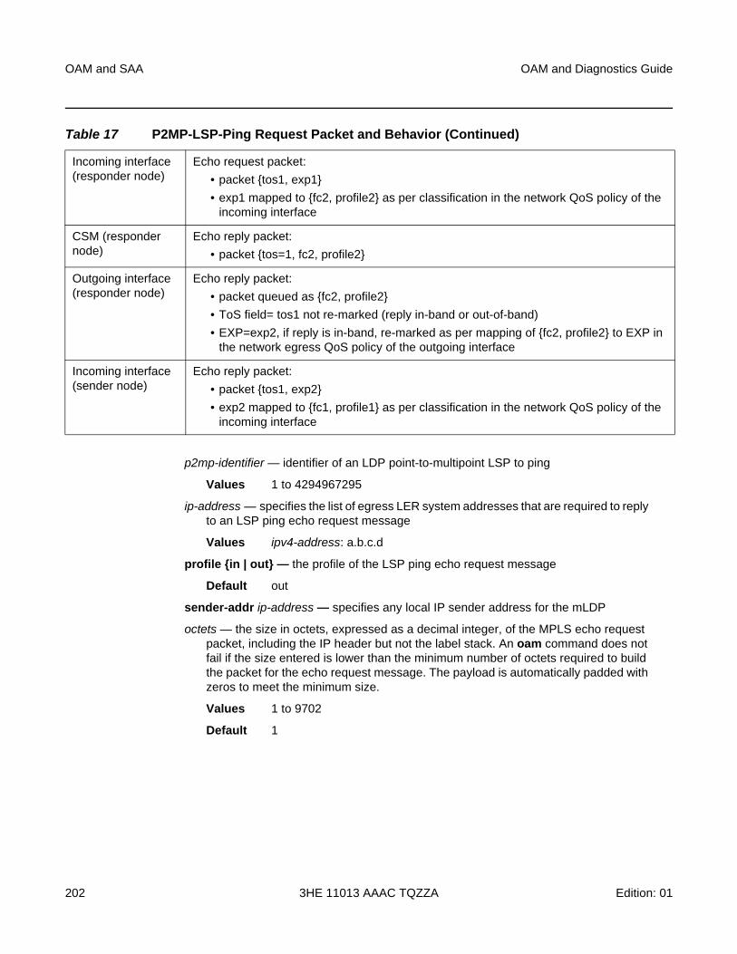
OAM and SAA
202
OAM and Diagnostics Guide
3HE 11013 AAAC TQZZA Edition: 01
p2mp-identifier — identifier of an LDP point-to-multipoint LSP to ping
Values 1 to 4294967295
ip-address — specifies the list of egress LER system addresses that are required to reply to an LSP ping echo request message
Values ipv4-address: a.b.c.d
profile {in | out} — the profile of the LSP ping echo request message
Default out
sender-addr ip-address — specifies any local IP sender address for the mLDP
octets — the size in octets, expressed as a decimal integer, of the MPLS echo request packet, including the IP header but not the label stack. An oam command does not fail if the size entered is lower than the minimum number of octets required to build the packet for the echo request message. The payload is automatically padded with zeros to meet the minimum size.
Values 1 to 9702
Default 1
Incoming interface (responder node)
Echo request packet:
• packet {tos1, exp1}
• exp1 mapped to {fc2, profile2} as per classification in the network QoS policy of the incoming interface
CSM (responder node)
Echo reply packet:
• packet {tos=1, fc2, profile2}
Outgoing interface (responder node)
Echo reply packet:
• packet queued as {fc2, profile2}
• ToS field= tos1 not re-marked (reply in-band or out-of-band)
• EXP=exp2, if reply is in-band, re-marked as per mapping of {fc2, profile2} to EXP in the network egress QoS policy of the outgoing interface
Incoming interface (sender node)
Echo reply packet:
• packet {tos1, exp2}
• exp2 mapped to {fc1, profile1} as per classification in the network QoS policy of the incoming interface
Table 17 P2MP-LSP-Ping Request Packet and Behavior (Continued)
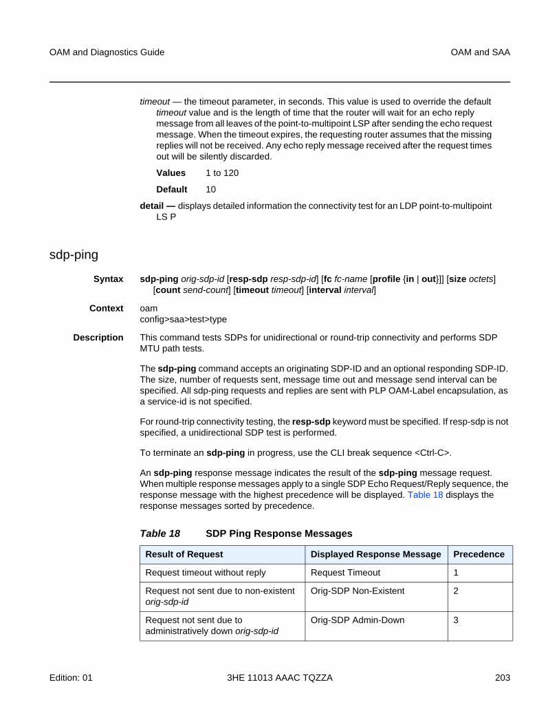
OAM and Diagnostics Guide OAM and SAA
Edition: 01 3HE 11013 AAAC TQZZA 203
timeout — the timeout parameter, in seconds. This value is used to override the default timeout value and is the length of time that the router will wait for an echo reply message from all leaves of the point-to-multipoint LSP after sending the echo request message. When the timeout expires, the requesting router assumes that the missing replies will not be received. Any echo reply message received after the request times out will be silently discarded.
Values 1 to 120
Default 10
detail — displays detailed information the connectivity test for an LDP point-to-multipoint LS P
sdp-ping
Syntax sdp-ping orig-sdp-id [resp-sdp resp-sdp-id] [fc fc-name [profile {in | out}]] [size octets] [count send-count] [timeout timeout] [interval interval]
Context oamconfig>saa>test>type
Description This command tests SDPs for unidirectional or round-trip connectivity and performs SDP MTU path tests.
The sdp-ping command accepts an originating SDP-ID and an optional responding SDP-ID. The size, number of requests sent, message time out and message send interval can be specified. All sdp-ping requests and replies are sent with PLP OAM-Label encapsulation, as a service-id is not specified.
For round-trip connectivity testing, the resp-sdp keyword must be specified. If resp-sdp is not specified, a unidirectional SDP test is performed.
To terminate an sdp-ping in progress, use the CLI break sequence <Ctrl-C>.
An sdp-ping response message indicates the result of the sdp-ping message request. When multiple response messages apply to a single SDP Echo Request/Reply sequence, the response message with the highest precedence will be displayed. Table 18 displays the response messages sorted by precedence.
Table 18 SDP Ping Response Messages
Result of Request Displayed Response Message Precedence
Request timeout without reply Request Timeout 1
Request not sent due to non-existent orig-sdp-id
Orig-SDP Non-Existent 2
Request not sent due to administratively down orig-sdp-id
Orig-SDP Admin-Down 3
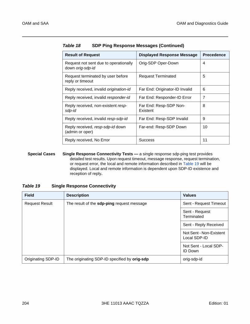
OAM and SAA
204
OAM and Diagnostics Guide
3HE 11013 AAAC TQZZA Edition: 01
Special Cases Single Response Connectivity Tests — a single response sdp-ping test provides detailed test results. Upon request timeout, message response, request termination, or request error, the local and remote information described in Table 19 will be displayed. Local and remote information is dependent upon SDP-ID existence and reception of reply.
Request not sent due to operationally down orig-sdp-id
Orig-SDP Oper-Down 4
Request terminated by user before reply or timeout
Request Terminated 5
Reply received, invalid origination-id Far End: Originator-ID Invalid 6
Reply received, invalid responder-id Far End: Responder-ID Error 7
Reply received, non-existent resp-sdp-id
Far End: Resp-SDP Non-Existent
8
Reply received, invalid resp-sdp-id Far End: Resp-SDP Invalid 9
Reply received, resp-sdp-id down (admin or oper)
Far-end: Resp-SDP Down 10
Reply received, No Error Success 11
Table 18 SDP Ping Response Messages (Continued)
Result of Request Displayed Response Message Precedence
Table 19 Single Response Connectivity
Field Description Values
Request Result The result of the sdp-ping request message Sent - Request Timeout
Sent - Request Terminated
Sent - Reply Received
Not Sent - Non-Existent Local SDP-ID
Not Sent - Local SDP-ID Down
Originating SDP-ID The originating SDP-ID specified by orig-sdp orig-sdp-id
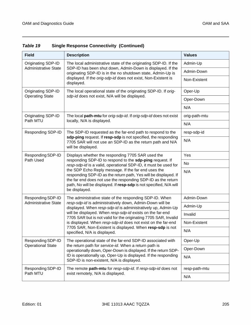
OAM and Diagnostics Guide OAM and SAA
Edition: 01 3HE 11013 AAAC TQZZA 205
Originating SDP-ID Administrative State
The local administrative state of the originating SDP-ID. If the SDP-ID has been shut down, Admin-Down is displayed. If the originating SDP-ID is in the no shutdown state, Admin-Up is displayed. If the orig-sdp-id does not exist, Non-Existent is displayed.
Admin-Up
Admin-Down
Non-Existent
Originating SDP-ID Operating State
The local operational state of the originating SDP-ID. If orig-sdp-id does not exist, N/A will be displayed.
Oper-Up
Oper-Down
N/A
Originating SDP-ID Path MTU
The local path-mtu for orig-sdp-id. If orig-sdp-id does not exist locally, N/A is displayed.
orig-path-mtu
N/A
Responding SDP-ID The SDP-ID requested as the far-end path to respond to the sdp-ping request. If resp-sdp is not specified, the responding 7705 SAR will not use an SDP-ID as the return path and N/A will be displayed.
resp-sdp-id
N/A
Responding SDP-ID Path Used
Displays whether the responding 7705 SAR used the responding SDP-ID to respond to the sdp-ping request. If resp-sdp-id is a valid, operational SDP-ID, it must be used for the SDP Echo Reply message. If the far end uses the responding SDP-ID as the return path, Yes will be displayed. If the far end does not use the responding SDP-ID as the return path, No will be displayed. If resp-sdp is not specified, N/A will be displayed.
Yes
No
N/A
Responding SDP-ID Administrative State
The administrative state of the responding SDP-ID. When resp-sdp-id is administratively down, Admin-Down will be displayed. When resp-sdp-id is administratively up, Admin-Up will be displayed. When resp-sdp-id exists on the far-end 7705 SAR but is not valid for the originating 7705 SAR, Invalid is displayed. When resp-sdp-id does not exist on the far-end 7705 SAR, Non-Existent is displayed. When resp-sdp is not specified, N/A is displayed.
Admin-Down
Admin-Up
Invalid
Non-Existent
N/A
Responding SDP-ID Operational State
The operational state of the far-end SDP-ID associated with the return path for service-id. When a return path is operationally down, Oper-Down is displayed. If the return SDP-ID is operationally up, Oper-Up is displayed. If the responding SDP-ID is non-existent, N/A is displayed.
Oper-Up
Oper-Down
N/A
Responding SDP-ID Path MTU
The remote path-mtu for resp-sdp-id. If resp-sdp-id does not exist remotely, N/A is displayed.
resp-path-mtu
N/A
Table 19 Single Response Connectivity (Continued)
Field Description Values
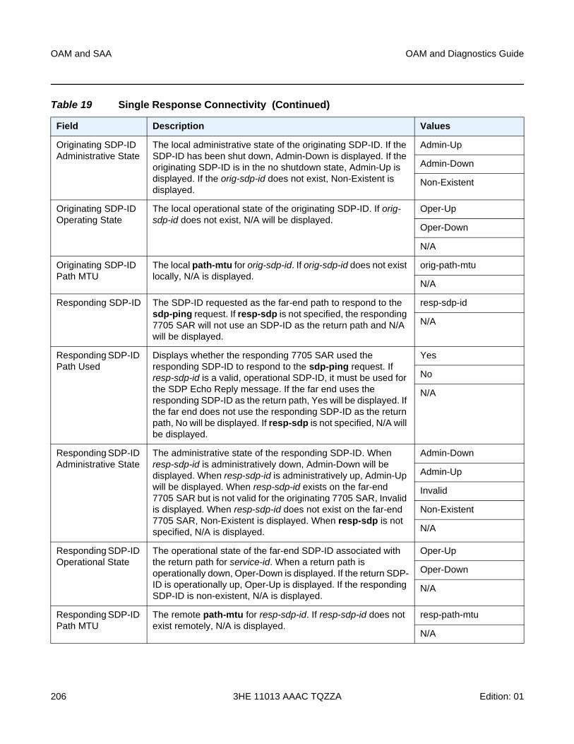
OAM and SAA
206
OAM and Diagnostics Guide
3HE 11013 AAAC TQZZA Edition: 01
Originating SDP-ID Administrative State
The local administrative state of the originating SDP-ID. If the SDP-ID has been shut down, Admin-Down is displayed. If the originating SDP-ID is in the no shutdown state, Admin-Up is displayed. If the orig-sdp-id does not exist, Non-Existent is displayed.
Admin-Up
Admin-Down
Non-Existent
Originating SDP-ID Operating State
The local operational state of the originating SDP-ID. If orig-sdp-id does not exist, N/A will be displayed.
Oper-Up
Oper-Down
N/A
Originating SDP-ID Path MTU
The local path-mtu for orig-sdp-id. If orig-sdp-id does not exist locally, N/A is displayed.
orig-path-mtu
N/A
Responding SDP-ID The SDP-ID requested as the far-end path to respond to the sdp-ping request. If resp-sdp is not specified, the responding 7705 SAR will not use an SDP-ID as the return path and N/A will be displayed.
resp-sdp-id
N/A
Responding SDP-ID Path Used
Displays whether the responding 7705 SAR used the responding SDP-ID to respond to the sdp-ping request. If resp-sdp-id is a valid, operational SDP-ID, it must be used for the SDP Echo Reply message. If the far end uses the responding SDP-ID as the return path, Yes will be displayed. If the far end does not use the responding SDP-ID as the return path, No will be displayed. If resp-sdp is not specified, N/A will be displayed.
Yes
No
N/A
Responding SDP-ID Administrative State
The administrative state of the responding SDP-ID. When resp-sdp-id is administratively down, Admin-Down will be displayed. When resp-sdp-id is administratively up, Admin-Up will be displayed. When resp-sdp-id exists on the far-end 7705 SAR but is not valid for the originating 7705 SAR, Invalid is displayed. When resp-sdp-id does not exist on the far-end 7705 SAR, Non-Existent is displayed. When resp-sdp is not specified, N/A is displayed.
Admin-Down
Admin-Up
Invalid
Non-Existent
N/A
Responding SDP-ID Operational State
The operational state of the far-end SDP-ID associated with the return path for service-id. When a return path is operationally down, Oper-Down is displayed. If the return SDP-ID is operationally up, Oper-Up is displayed. If the responding SDP-ID is non-existent, N/A is displayed.
Oper-Up
Oper-Down
N/A
Responding SDP-ID Path MTU
The remote path-mtu for resp-sdp-id. If resp-sdp-id does not exist remotely, N/A is displayed.
resp-path-mtu
N/A
Table 19 Single Response Connectivity (Continued)
Field Description Values
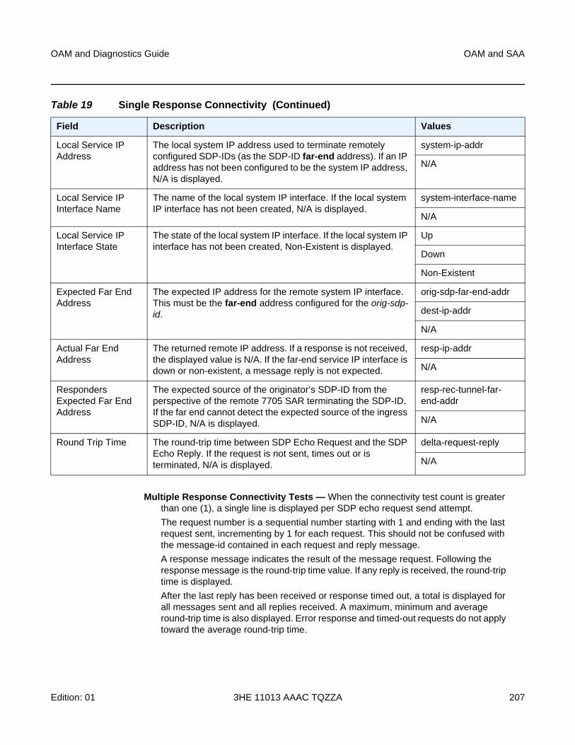
OAM and Diagnostics Guide OAM and SAA
Edition: 01 3HE 11013 AAAC TQZZA 207
Multiple Response Connectivity Tests — When the connectivity test count is greater than one (1), a single line is displayed per SDP echo request send attempt.
The request number is a sequential number starting with 1 and ending with the last request sent, incrementing by 1 for each request. This should not be confused with the message-id contained in each request and reply message.
A response message indicates the result of the message request. Following the response message is the round-trip time value. If any reply is received, the round-trip time is displayed.
After the last reply has been received or response timed out, a total is displayed for all messages sent and all replies received. A maximum, minimum and average round-trip time is also displayed. Error response and timed-out requests do not apply toward the average round-trip time.
Local Service IP Address
The local system IP address used to terminate remotely configured SDP-IDs (as the SDP-ID far-end address). If an IP address has not been configured to be the system IP address, N/A is displayed.
system-ip-addr
N/A
Local Service IP Interface Name
The name of the local system IP interface. If the local system IP interface has not been created, N/A is displayed.
system-interface-name
N/A
Local Service IP Interface State
The state of the local system IP interface. If the local system IP interface has not been created, Non-Existent is displayed.
Up
Down
Non-Existent
Expected Far End Address
The expected IP address for the remote system IP interface. This must be the far-end address configured for the orig-sdp-id.
orig-sdp-far-end-addr
dest-ip-addr
N/A
Actual Far End Address
The returned remote IP address. If a response is not received, the displayed value is N/A. If the far-end service IP interface is down or non-existent, a message reply is not expected.
resp-ip-addr
N/A
Responders Expected Far End Address
The expected source of the originator’s SDP-ID from the perspective of the remote 7705 SAR terminating the SDP-ID. If the far end cannot detect the expected source of the ingress SDP-ID, N/A is displayed.
resp-rec-tunnel-far-end-addr
N/A
Round Trip Time The round-trip time between SDP Echo Request and the SDP Echo Reply. If the request is not sent, times out or is terminated, N/A is displayed.
delta-request-reply
N/A
Table 19 Single Response Connectivity (Continued)
Field Description Values
OAM and SAA
208
OAM and Diagnostics Guide
3HE 11013 AAAC TQZZA Edition: 01
Parameters orig-sdp-id — the SDP-ID to be used by sdp-ping, expressed as a decimal integer. The far-end address of the specified SDP-ID is the expected responder-id within each reply received. The specified SDP-ID defines the SDP tunnel encapsulation used to reach the far end — GRE, IP, or MPLS. If orig-sdp-id is invalid or administratively down or unavailable for some reason, the SDP echo request message is not sent and an appropriate error message is displayed (once the interval timer expires, sdp-ping will attempt to send the next request if required).
Values 1 to 17407
resp-sdp-id — specifies the return SDP-ID to be used by the far-end 7705 SAR for the message reply for round-trip SDP connectivity testing. If resp-sdp-id does not exist on the far-end 7705 SAR, terminates on another 7705 SAR different from the originating 7705 SAR, or another issue prevents the far-end 7705 SAR from using resp-sdp-id, the SDP echo reply will be sent using generic OAM encapsulation. The received forwarding class (as mapped on the ingress network interface for the far end) defines the forwarding class encapsulation for the reply message.
This is an optional parameter.
Values 1 to 17407
Default null – use the non-SDP return path for message reply
fc-name — indicates the forwarding class of the SDP encapsulation. The actual forwarding class encoding is controlled by the network egress DSCP or LSP-EXP mappings.
The DSCP or LSP-EXP mappings on the receive network interface control the mapping back to the internal forwarding class used by the far-end 7705 SAR that receives the message request. The egress mappings of the egress network interface on the far-end 7705 SAR control the forwarding class markings on the return reply message.
The DSCP or LSP-EXP mappings on the receive network interface control the mapping of the message reply back at the originating 7705 SAR. This is displayed in the response message output upon receipt of the message reply.
Values be, l2, af, l1, h2, ef, h1, nc
Default be
profile {in | out} — specifies the profile state of the SDP encapsulation
Default out
octets — the size of the packet in octets, expressed as a decimal integer. This parameter is used to override the default message size for the sdp-ping request. Changing the message size is a method of checking the ability of an SDP to support a path-mtu. The size of the message does not include the SDP encapsulation, VC-Label (if applied) or any DLC headers or trailers.
OAM and Diagnostics Guide OAM and SAA
Edition: 01 3HE 11013 AAAC TQZZA 209
When the OAM message request is encapsulated in an SDP, the IP DF (Do not fragment) bit is set. If any segment of the path between the sender and receiver cannot handle the message size, the message is discarded. MPLS LSPs are not expected to fragment the message either, as the message contained in the LSP is not an IP packet.
Values 72 to 9702
Default 40
send-count — the number of messages to send, expressed as a decimal integer. The count parameter is used to override the default number of message requests sent. Each message request must either time out or receive a reply before the next message request is sent. The message interval value must be expired before the next message request is sent.
Values 1 to 100
Default 1
timeout — specifies the amount of time that the router will wait for a message reply after sending the message request. If the timeout expires, the requesting router assumes that the message response will not be received. A “request timeout” message is displayed by the CLI for each message request sent that expires. Any response received after the request times out will be silently discarded.
This value is used to override the default timeout value.
Values 1 to 10
Default 5
interval — specifies the minimum amount of time that must expire before the next message request is sent.
If the interval is set to 1 second, and the timeout value is set to 10 seconds, then the maximum time between message requests is 10 seconds and the minimum is 1 second. This depends upon the receipt of a message reply corresponding to the outstanding message request.
This parameter is used to override the default request message send interval.
Values 1 to 10
Default 1
Output The following outputs are examples of SDP ping information.
Single Response Round-trip Connectivity Test Output Example
A:router1> oam sdp-ping 10 resp-sdp 22 fc efErr SDP-ID Info Local Remote--------------------------------------------------
SDP-ID: 10 22Administrative State: Up UpOperative State: Up UpPath MTU: 4470 4470Response SDP Used: Yes
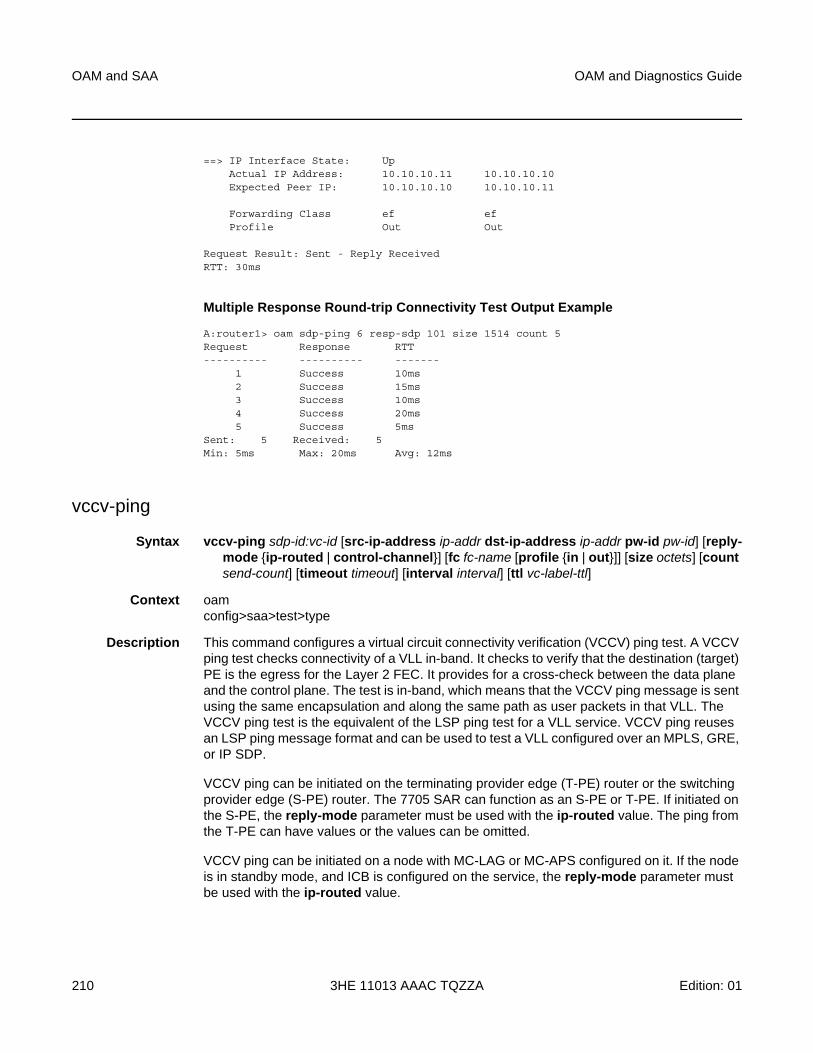
OAM and SAA
210
OAM and Diagnostics Guide
3HE 11013 AAAC TQZZA Edition: 01
==> IP Interface State: UpActual IP Address: 10.10.10.11 10.10.10.10Expected Peer IP: 10.10.10.10 10.10.10.11
Forwarding Class ef efProfile Out Out
Request Result: Sent - Reply ReceivedRTT: 30ms
Multiple Response Round-trip Connectivity Test Output Example
A:router1> oam sdp-ping 6 resp-sdp 101 size 1514 count 5Request Response RTT---------- ---------- -------
1 Success 10ms2 Success 15ms3 Success 10ms4 Success 20ms5 Success 5ms
Sent: 5 Received: 5Min: 5ms Max: 20ms Avg: 12ms
vccv-ping
Syntax vccv-ping sdp-id:vc-id [src-ip-address ip-addr dst-ip-address ip-addr pw-id pw-id] [reply-mode {ip-routed | control-channel}] [fc fc-name [profile {in | out}]] [size octets] [count send-count] [timeout timeout] [interval interval] [ttl vc-label-ttl]
Context oamconfig>saa>test>type
Description This command configures a virtual circuit connectivity verification (VCCV) ping test. A VCCV ping test checks connectivity of a VLL in-band. It checks to verify that the destination (target) PE is the egress for the Layer 2 FEC. It provides for a cross-check between the data plane and the control plane. The test is in-band, which means that the VCCV ping message is sent using the same encapsulation and along the same path as user packets in that VLL. The VCCV ping test is the equivalent of the LSP ping test for a VLL service. VCCV ping reuses an LSP ping message format and can be used to test a VLL configured over an MPLS, GRE, or IP SDP.
VCCV ping can be initiated on the terminating provider edge (T-PE) router or the switching provider edge (S-PE) router. The 7705 SAR can function as an S-PE or T-PE. If initiated on the S-PE, the reply-mode parameter must be used with the ip-routed value. The ping from the T-PE can have values or the values can be omitted.
VCCV ping can be initiated on a node with MC-LAG or MC-APS configured on it. If the node is in standby mode, and ICB is configured on the service, the reply-mode parameter must be used with the ip-routed value.
OAM and Diagnostics Guide OAM and SAA
Edition: 01 3HE 11013 AAAC TQZZA 211
If a VCCV ping is initiated from a T-PE to a neighboring S-PE (one segment only), only the sdp-id:vc-id parameter must be used. However, if the ping is across two or more segments, the sdp-id:vc-id, src-ip-address ip-addr, dst-ip-address ip-addr, ttl vc-label-ttl and pw-id pw-id parameters must be used, where:
• the src-ip-address is the system IP address of the router preceding the destination router
• the pw-id is the VC ID of the last pseudowire segment
• the vc-label-ttl must have a value equal to or greater than the number of pseudowire segments
VCCV ping on multi-segment pseudowires require that the control word be enabled in all segments of the VLL. If the control word is not enabled on spoke SDP it will not be signaled peer VCCV CC bits to the far end, consequently VCCV ping cannot be successfully initiated on that specific spoke SDP.
Parameters sdp-id:vc-id — identifies the virtual circuit of the pseudowire being tested. The VC ID must exist on the local router and the far-end peer must indicate that it supports VCCV to allow the user to send a vccv-ping message.
This is a mandatory parameter.
Values sdp-id: 1 to 17407
vc-id: 1 to 2147483647
src-ip-address ip-addr — specifies the source IP address
Values ipv4-address: a.b.c.d
dst-ip-address ip-addr — specifies the destination IP address
Values ipv4-address: a.b.c.d
pw-id — specifies the pseudowire ID to be used for performing a vccv-ping operation. The pseudowire ID is a non-zero, 32-bit connection ID required by the FEC 128, as defined in RFC 4379, Detecting Multi-Protocol Label Switched (MPLS) Data Plane Failures.
Values 0 to 4294967295
reply-mode {ip-routed | control-channel} — specifies the method for sending the reply message to the far-end 7705 SAR
This is a mandatory parameter.
Values ip-routed — indicates a reply mode out-of-band using UDP IPv4
control-channel — indicates a reply mode in-band using VCCV control channel
Default control-channel
fc-name — indicates the forwarding class of the MPLS echo request packets. The actual forwarding class encoding is controlled by the network egress LSP-EXP mappings.
OAM and SAA
212
OAM and Diagnostics Guide
3HE 11013 AAAC TQZZA Edition: 01
The LSP-EXP mappings on the receive network interface control the mapping back to the internal forwarding class used by the far-end 7705 SAR that receives the message request. The egress mappings of the egress network interface on the far-end router control the forwarding class markings on the return reply message.
The LSP-EXP mappings on the receive network interface control the mapping of the message reply back at the originating SAR.
Values be, l2, af, l1, h2, ef, h1, nc
Default be
profile {in | out} — specifies the profile state of the MPLS echo request encapsulation
Default out
octets — specifies the VCCV ping echo request packet size in octets, expressed as a decimal integer. The request payload is padded with zeros to the specified size.
Values 88 to 9702
Default 88
send-count — the number of messages to send, expressed as a decimal integer. The count parameter is used to override the default number of message requests sent. Each message request must either time out or receive a reply before the next message request is sent. The message interval value must be expired before the next message request is sent.
Values 1 to 100
Default 1
timeout — specifies the amount of time that the router will wait for a message reply after sending the message request. If the timeout expires, the requesting router assumes that the message response will not be received. A “request timeout” message is displayed by the CLI for each message request sent that expires. Any response received after the request times out will be silently discarded.
This value is used to override the default timeout value.
Values 1 to 10
Default 5
interval — specifies the minimum amount of time that must expire before the next message request is sent.
If the interval is set to 1 second, and the timeout value is set to 10 seconds, then the maximum time between message requests is 10 seconds and the minimum is 1 second. This depends upon the receipt of a message reply corresponding to the outstanding message request.
This parameter is used to override the default request message send interval.
Values 1 to 10
Default 1
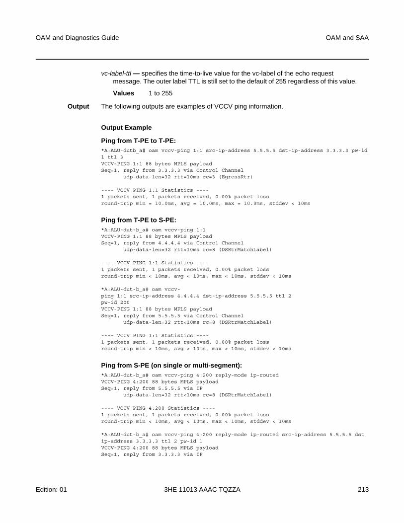
OAM and Diagnostics Guide OAM and SAA
Edition: 01 3HE 11013 AAAC TQZZA 213
vc-label-ttl — specifies the time-to-live value for the vc-label of the echo request message. The outer label TTL is still set to the default of 255 regardless of this value.
Values 1 to 255
Output The following outputs are examples of VCCV ping information.
Output Example
Ping from T-PE to T-PE:*A:ALU-dutb_a# oam vccv-ping 1:1 src-ip-address 5.5.5.5 dst-ip-address 3.3.3.3 pw-id1 ttl 3VCCV-PING 1:1 88 bytes MPLS payloadSeq=1, reply from 3.3.3.3 via Control Channel
udp-data-len=32 rtt=10ms rc=3 (EgressRtr)
---- VCCV PING 1:1 Statistics ----1 packets sent, 1 packets received, 0.00% packet lossround-trip min = 10.0ms, avg = 10.0ms, max = 10.0ms, stddev < 10ms
Ping from T-PE to S-PE:*A:ALU-dut-b_a# oam vccv-ping 1:1VCCV-PING 1:1 88 bytes MPLS payloadSeq=1, reply from 4.4.4.4 via Control Channel
udp-data-len=32 rtt<10ms rc=8 (DSRtrMatchLabel)
---- VCCV PING 1:1 Statistics ----1 packets sent, 1 packets received, 0.00% packet lossround-trip min < 10ms, avg < 10ms, max < 10ms, stddev < 10ms
*A:ALU-dut-b_a# oam vccv-ping 1:1 src-ip-address 4.4.4.4 dst-ip-address 5.5.5.5 ttl 2pw-id 200VCCV-PING 1:1 88 bytes MPLS payloadSeq=1, reply from 5.5.5.5 via Control Channel
udp-data-len=32 rtt<10ms rc=8 (DSRtrMatchLabel)
---- VCCV PING 1:1 Statistics ----1 packets sent, 1 packets received, 0.00% packet lossround-trip min < 10ms, avg < 10ms, max < 10ms, stddev < 10ms
Ping from S-PE (on single or multi-segment):*A:ALU-dut-b_a# oam vccv-ping 4:200 reply-mode ip-routedVCCV-PING 4:200 88 bytes MPLS payloadSeq=1, reply from 5.5.5.5 via IP
udp-data-len=32 rtt<10ms rc=8 (DSRtrMatchLabel)
---- VCCV PING 4:200 Statistics ----1 packets sent, 1 packets received, 0.00% packet lossround-trip min < 10ms, avg < 10ms, max < 10ms, stddev < 10ms
*A:ALU-dut-b_a# oam vccv-ping 4:200 reply-mode ip-routed src-ip-address 5.5.5.5 dstip-address 3.3.3.3 ttl 2 pw-id 1VCCV-PING 4:200 88 bytes MPLS payloadSeq=1, reply from 3.3.3.3 via IP
OAM and SAA
214
OAM and Diagnostics Guide
3HE 11013 AAAC TQZZA Edition: 01
udp-data-len=32 rtt<10ms rc=3 (EgressRtr)
---- VCCV PING 4:200 Statistics ----1 packets sent, 1 packets received, 0.00% packet lossround-trip min < 10ms, avg < 10ms, max < 10ms, stddev < 10ms
vccv-trace
Syntax vccv-trace sdp-id:vc-id [size octets] [min-ttl min-vc-label-ttl] [max-ttl max-vc-label-ttl] [max-fail no-response-count] [probe-count probe-count] [reply-mode {ip-routed | control-channel}] [timeout timeout-value] [interval interval-value] [fc fc-name [profile {in |out}]] [detail]
Context oamconfig>saa>test>type
Description This command configures a Virtual Circuit Connectivity Verification (VCCV) automated trace test. The automated VCCV trace can trace the entire path of a PW with a single command issued at the terminating PE (T-PE) or at a switching PE (S-PE). VCCV trace is equivalent to LSP trace and is an iterative process by which the source T-PE or S-PE node sends successive VCCV ping messages with incrementing TTL values, starting from TTL=1.
In each iteration, the T-PE builds the MPLS echo request message in a way similar to VCCV ping. The first message (with TTL=1) includes the next-hop S-PE targeted LDP session source address in the Remote PE Address field of the PW FEC TLV. Each S-PE that terminates and processes the message will include the FEC 128 TLV corresponding to the PW segment to its downstream node in the MPLS echo reply message.The source T-PE or S-PE node can then build the next echo reply message with TTL=2 to test the next-next hop for the MS-PW. It will copy the FEC TLV it received in the echo reply message into the new echo request message. The process is terminated when the reply is from the egress T-PE or when a timeout occurs.
VCCV trace can be initiated on a node with MC-LAG or MC-APS configured on it. If the node is in standby mode, and ICB is configured on the service, the reply-mode parameter must be used with the ip-routed value.
The user can specify to display the result of the VCCV trace for a fewer number of PW segments of the end-to-end MS-PW path. In this case, the min-ttl and max-ttl parameters should be configured accordingly. However, the T-PE or S-PE node will still probe all hops up to min-ttl in order to correctly build the FEC of the desired subset of segments.
Parameters sdp-id:vc-id — specifies the VC ID of the pseudowire being tested. The VC ID must exist on the local 7705 SAR and the far-end peer must indicate that it supports VCCV to allow the user to send a VCCV ping message.
Values sdp-id: 1 to 17407
vc-id: 1 to 4294967295
OAM and Diagnostics Guide OAM and SAA
Edition: 01 3HE 11013 AAAC TQZZA 215
octets — specifies the VCCV ping echo request packet size, in octets, expressed as a decimal integer. The request payload is padded with zeros to the specified size.
Values 88 to 9702
Default 88
min-vc-label-ttl — specifies the TTL value for the VC label of the echo request message for the first hop of the MS-PW for which the results are to be displayed. This is expressed as a decimal integer. The outer label TTL is still set to the default of 255 regardless of the value of the VC label.
Values 1 to 255
Default 1
max-vc-label-tt — specifies the TTL value for the VC label of the echo request message for the last hop of the MS-PW for which the results are to be displayed. This is expressed as a decimal integer. The outer label TTL is still set to the default of 255 regardless of the value of the VC label.
Values 1 to 255
Default 8
no-response-count — specifies the maximum number of consecutive VCCV trace echo requests, expressed as a decimal integer, that do not receive a reply before the trace operation fails for a given TTL value.
Values 1 to 255
Default 5
probe-count — specifies the number of VCCV trace echo request messages to send per TTL value
Values 1 to 10
Default 1
reply-mode {ip-routed | control-channel} — specifies the method for sending the reply message to the far-end 7705 SAR. This is a mandatory parameter.
Values ip-routed — indicates a reply mode out-of-band using UDP IPv4
control-channel — indicates a reply mode in-band using the VCCV control channel
When a VCCV-trace message is originated from an S-PE node, the user should use the IPv4 reply mode because the replying node does not know how to set the TTL to reach the sending SPE node. If the user attempts this, a warning is issued to use the IPv4 reply mode.
Default control-channel
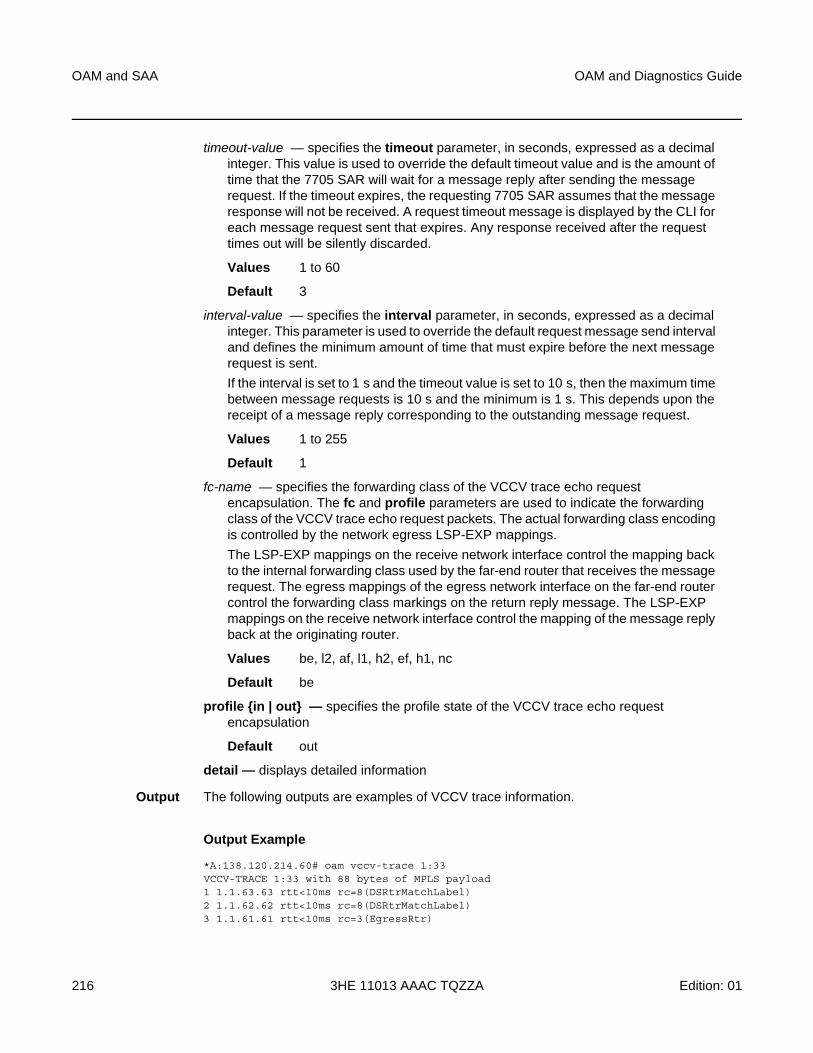
OAM and SAA
216
OAM and Diagnostics Guide
3HE 11013 AAAC TQZZA Edition: 01
timeout-value — specifies the timeout parameter, in seconds, expressed as a decimal integer. This value is used to override the default timeout value and is the amount of time that the 7705 SAR will wait for a message reply after sending the message request. If the timeout expires, the requesting 7705 SAR assumes that the message response will not be received. A request timeout message is displayed by the CLI for each message request sent that expires. Any response received after the request times out will be silently discarded.
Values 1 to 60
Default 3
interval-value — specifies the interval parameter, in seconds, expressed as a decimal integer. This parameter is used to override the default request message send interval and defines the minimum amount of time that must expire before the next message request is sent.
If the interval is set to 1 s and the timeout value is set to 10 s, then the maximum time between message requests is 10 s and the minimum is 1 s. This depends upon the receipt of a message reply corresponding to the outstanding message request.
Values 1 to 255
Default 1
fc-name — specifies the forwarding class of the VCCV trace echo request encapsulation. The fc and profile parameters are used to indicate the forwarding class of the VCCV trace echo request packets. The actual forwarding class encoding is controlled by the network egress LSP-EXP mappings.
The LSP-EXP mappings on the receive network interface control the mapping back to the internal forwarding class used by the far-end router that receives the message request. The egress mappings of the egress network interface on the far-end router control the forwarding class markings on the return reply message. The LSP-EXP mappings on the receive network interface control the mapping of the message reply back at the originating router.
Values be, l2, af, l1, h2, ef, h1, nc
Default be
profile {in | out} — specifies the profile state of the VCCV trace echo request encapsulation
Default out
detail — displays detailed information
Output The following outputs are examples of VCCV trace information.
Output Example
*A:138.120.214.60# oam vccv-trace 1:33VCCV-TRACE 1:33 with 88 bytes of MPLS payload1 1.1.63.63 rtt<10ms rc=8(DSRtrMatchLabel)2 1.1.62.62 rtt<10ms rc=8(DSRtrMatchLabel)3 1.1.61.61 rtt<10ms rc=3(EgressRtr)

OAM and Diagnostics Guide OAM and SAA
Edition: 01 3HE 11013 AAAC TQZZA 217
Trace with detail:*A:ALU2>oam vccv-trace 1:33 detailVCCV-TRACE 1:33 with 88 bytes of MPLS payload1 1.1.63.63 rtt<10ms rc=8(DSRtrMatchLabel)Next segment: VcId=34 VcType=AAL5SDU Source=1.1.63.63 Remote=1.1.62.622 1.1.62.62 rtt<10ms rc=8(DSRtrMatchLabel)Next segment: VcId=35 VcType=AAL5SDU Source=1.1.62.62 Remote=1.1.61.613 1.1.61.61 rtt<10ms rc=3(EgressRtr)----------------------------------------------*A:ALU2>oam vccv-trace#
vprn-ping
Syntax vprn-ping [service-id | service service-name] source ip-address destination ip-address [fc fc-name [profile [in | out]] [size size] [ttl vc-label-ttl] [count send-count] [return-control] [timeout timeout] [interval seconds]
Context oamconfig>saa>test>type
Description This command performs a VPRN ping.
Parameters service-id — the VPRN service ID to diagnose or manage
Values 1 to 2147483647
service-name — the service name, up to 64 characters
source ip-address — the IP prefix for the source IP address
Values ipv4-address a.b.c.d
ipv6-address x:x:x:x:x:x:x:x (eight 16-bit pieces)
x:x:x:x:x:x:d.d.d.d
x: [0 to FFFF]H
d: [0 to 255]D
destination ip-address — the IP prefix for the destination IP address
Values ipv4-address a.b.c.d
ipv6-address x:x:x:x:x:x:x:x (eight 16-bit pieces)
x:x:x:x:x:x:d.d.d.d
x: [0 to FFFF]H
d: [0 to 255]D
size — the OAM request packet size in octets, expressed as a decimal integer
Values 1 to 9702
OAM and SAA
218
OAM and Diagnostics Guide
3HE 11013 AAAC TQZZA Edition: 01
vc-label-ttl — the TTL value in the VC label for the OAM request, expressed as a decimal integer
Values 1 to 255
Default 255
return-control — specifies the response to come on the control plane.
seconds — the interval parameter in seconds, expressed as a decimal integer. This parameter is used to override the default request message send interval and defines the minimum amount of time that must expire before the next message request is sent.
If the interval is set to 1 second where the timeout value is set to 10 seconds, then the maximum time between message requests is 10 seconds and the minimum is 1 second. This depends upon the receipt of a message reply corresponding to the outstanding message request.
Values 1 to 10
Default 1
send-count — the number of messages to send, expressed as a decimal integer. The count parameter is used to override the default number of message requests sent. Each message request must either time out or receive a reply before the next message request is sent. The message interval value must be expired before the next message request is sent.
Values 1 to 100
Default 1
timeout — the timeout parameter in seconds, expressed as a decimal integer. This value is used to override the default timeout value and is the amount of time that the router will wait for a message reply after sending the message request. If the timeout expires, the requesting router assumes that the message response will not be received. Any response received after the request times out will be silently discarded.
Values 1 to 100
Default 5
fc-name — the forwarding class of the MPLS echo request encapsulation
Values be, l2, af, l1, h2, ef, h1, nc
Default be
profile {in | out} — the profile state of the MPLS echo request encapsulation
Default out
Output The following output is an example of VPRN ping information.
Output Example
A:PE_1# oam vprn-ping 25 source 10.4.128.1 destination 10.16.128.0Sequence Node-id Reply-Path Size RTT
OAM and Diagnostics Guide OAM and SAA
Edition: 01 3HE 11013 AAAC TQZZA 219
----------------------------------------------------------------------------[Send request Seq. 1.]1 10.128.0.3:cpm In-Band 100 0ms----------------------------------------------------------------------------...A:PE_1#
vprn-trace
Syntax vprn-trace [service-id | service service-name] source ip-address destination ip-address [fc fc-name [profile [in | out]] [size size] [min-ttl vc-label-ttl] [max-ttl vc-label-ttl] [probe-count send-count] [return-control] [timeout timeout] [interval seconds]
Context oamconfig>saa>test>type
Description This command performs a VPRN trace.
Parameters service-id — the VPRN service ID to diagnose or manage
Values 1 to 2147483647
service-name — the service name, up to 64 characters
source ip-address — the IP prefix for the source IP address
Values ipv4-address a.b.c.d
ipv6-address x:x:x:x:x:x:x:x (eight 16-bit pieces)
x:x:x:x:x:x:d.d.d.d
x: [0 to FFFF]H
d: [0 to 255]D
destination ip-address — the IP prefix for the destination IP address
Values ipv4-address a.b.c.d
ipv6-address x:x:x:x:x:x:x:x (eight 16-bit pieces)
x:x:x:x:x:x:d.d.d.d
x: [0 to FFFF]H
d: [0 to 255]D
size — the OAM request packet size in octets, expressed as a decimal integer
Values 1 to 9702
min-ttl vc-label-ttl — the minimum TTL value in the VC label for the trace test, expressed as a decimal integer
Values 1 to 255
Default 1
OAM and SAA
220
OAM and Diagnostics Guide
3HE 11013 AAAC TQZZA Edition: 01
max-ttl vc-label-ttl — the maximum TTL value in the VC label for the trace test, expressed as a decimal integer
Values 1 to 255
Default 4
return-control — specifies the OAM reply to a data plane OAM request be sent using the control plane instead of the data plane
Default OAM reply sent using the data plane.
send-count — the number of OAM requests sent for a particular TTL value, expressed as a decimal integer
Values 1 to 10
Default 1
seconds — the interval parameter in seconds, expressed as a decimal integer. This parameter is used to override the default request message send interval and defines the minimum amount of time that must expire before the next message request is sent.
If the interval is set to 1 second where the timeout value is set to 10 seconds, then the maximum time between message requests is 10 seconds and the minimum is 1 second. This depends upon the receipt of a message reply corresponding to the outstanding message request.
Values 1 to 10
Default 1
timeout — the timeout parameter in seconds, expressed as a decimal integer. This value is used to override the default timeout value and is the amount of time that the router will wait for a message reply after sending the message request. If the timeout expires, the requesting router assumes that the message response will not be received. Any response received after the request times out will be silently discarded.
Values 1 to 10
Default 3
fc-name — the forwarding class of the MPLS echo request encapsulation
Values be, l2, af, l1, h2, ef, h1, nc
Default be
profile {in | out} — the profile state of the MPLS echo request encapsulation
Default out
Output The following output is an example of VPRN trace information.
Output Example
A:PE_1# oam vprn-trace 25 source 10.4.128.1 destination 10.16.128.0TTL Seq Reply Node-id Rcvd-on Reply-Path RTT
OAM and Diagnostics Guide OAM and SAA
Edition: 01 3HE 11013 AAAC TQZZA 221
----------------------------------------------------------------------------[Send request TTL: 1, Seq. 1.]1 1 1 10.128.0.4 cpm In-Band 0msRequestor 10.128.0.1 Route: 0.0.0.0/0Vpn Label: 131071 Metrics 0 Pref 170 Owner bgpVpnNext Hops: [1] ldp tunnelRoute Targets: [1]: target:65100:1Responder 10.128.0.4 Route: 10.16.128.0/24Vpn Label: 131071 Metrics 0 Pref 170 Owner bgpVpnNext Hops: [1] ldp tunnelRoute Targets: [1]: target:65001:100
[Send request TTL: 2, Seq. 1.]2 1 1 10.128.0.3 cpm In-Band 0msRequestor 10.128.0.1 Route: 0.0.0.0/0Vpn Label: 131071 Metrics 0 Pref 170 O wner bgpVpnNext Hops: [1] ldp tunnelRoute Targets: [1]: target:65100:1Responder 10.128.0.3 Route: 10.16.128.0/24Vpn Label: 0 Metrics 0 Pref 0 Owner localNext Hops: [1] ifIdx 2 nextHopIp 10.16.128.0[Send request TTL: 3, Seq. 1.][Send request TTL: 4, Seq. 1.]...----------------------------------------------------------------------------A:PE_1#
enable-icmp-vse
Syntax [no] enable-icmp-vse
Context config>system
Description This command is a global command that enables and disables one-way timestamping of outbound SAA ICMP ping packets. Enabling one-way timestamping on a 7705 SAR node requires enable-icmp-vse to be set on both the near-end and far-end nodes. The current status can be seen on the show>system>information CLI display.
The -vse part of the command means vendor-specific extension.
The no form of this command disables one-way timestamping.
Default no enable-icmp-vse
OAM and SAA
222
OAM and Diagnostics Guide
3HE 11013 AAAC TQZZA Edition: 01
3.6.2.1.9 Y.1564 Diagnostics
testhead
Syntax testhead test-name [owner test-owner] testhead-profile profile-id [frame-payload frame-payload-id] sap sap-id [acceptance-criteria acceptance-criteria-id [color-aware {enable | disable}] [performance-monitoring {enable | disable}]
testhead test-name owner test-owner stop
Context oam
Description This command initiates an ITU-T Y.1564 test for throughput and bandwidth testing of Ethernet point-to-point virtual circuits. The test is run using sets of threshold and payload values that are configured under testhead-profile and frame-payload. You can run tests with up to four parallel flows by specifying up to four frame payload IDs in order to create IMIX-type traffic patterns.
After a test is complete, the system raises an SNMP trap.
Before initiating a test, you must also enable an Ethernet loopback with the loopback command, in order to send the test packets back to the source for measuring and analyzing. No checks are performed to verify that a remote SAP loopback is enabled
Parameters test-name — the Y.1564 test name, up to 32 characters in length
test-owner — the owner of a Y.1564 test, up to 32 characters in length
profile-id — the test head profile to be used for this test
Values 1 to 32
frame-payload-id — a list of up to four frame-payload-ids defined under one testhead-profile template; For example, 1-2, 4
Values 1 to 8
sap-id — the local SAP identifier to associate with the Y.1564 test head
acceptance-criteria-id — specifies which acceptance criteria group to include with the test head
Values 1 to 8
color-aware — configures the Y.1564 test to be color-aware. If enabled, the test compares the packet, jitter, and loss results to the in-profile and out-of-profile threshold settings. If disabled, the test compares packet, jitter, and loss results to their respective generic threshold values.

OAM and Diagnostics Guide OAM and SAA
Edition: 01 3HE 11013 AAAC TQZZA 223
performance-monitoring — enables or disables performance monitoring tests. The test head generates time-stamped marker packets for measuring end-to-end, round-trip delay and jitter. These packets are injected along with standard filler packets used for throughput testing and can drastically skew test results, especially in tests with low bandwidth and large frame sizes.
Default enable
stop — ends an ITU-T Y.1564 test before it is complete
testhead-marker-packet-src-mac
Syntax testhead-marker-packet-src-mac mac-address
Context config>test-oam
Description This command configures the source MAC address for Y.1564 test head marker packets.
The default value is all zeros. It is recommended that users provision this values to a unique value for the tested network, since the packet will not traverse Layer 2 networks.
Parameters mac-address — a unicast destination MAC address
Values xx:xx:xx:xx:xx:xx or xx-xx-xx-xx-xx-xx, where xx is a hexadecimal number
Default all zeros
testhead-profile
Syntax testhead-profile profile-id [create]
Context config>test-oam
Description This command creates an ITU-T Y.1564 test head profile. The test head acts like a template that can be configured with groupings of threshold and frame payload values in order to create a variety of IYU-T Y.1564 tests.
On adapter cards, one test head is supported per card. On the 7705 SAR-A, 7705 SAR-Ax, 7705 SAR-H, 7705 SAR-Hc, 7705 SAR-M, 7705 SAR-W, and 7705 SAR-Wx, one test head is supported per node. On the 7705 SAR-X, one test head is supported on MDA 2 and one on MDA 3.
Parameters profile-id — 1 to 32
OAM and SAA
224
OAM and Diagnostics Guide
3HE 11013 AAAC TQZZA Edition: 01
acceptance-criteria
Syntax acceptance-criteria acceptance-criteria-id [create]
no acceptance-criteria
Context config>test-oam>testhead-profile
Description This command configures a group of acceptance criteria thresholds, such as packet loss and jitter, to be associated with an ITU-T Y.1564 test head.
The no form of this command deletes the acceptance criteria group and all threshold values configured under it.
Parameters acceptance-criteria-id — assigns an ID number to a group of acceptance criteria
Values 1 to 8
cir-threshold
Syntax cir-threshold cir-threshold
no cir-threshold
Context config>test-oam>testhead-profile>acceptance-criteria
Description This command configures the CIR threshold associated with the ITU-T Y.1564 test head.
Default no cir-threshold
Parameters cir-threshold — the CIR threshold in kilobits per second
Values 0 to 1000000
jitter-rising-threshold
Syntax jitter-rising-threshold threshold
no jitter-rising-threshold
Context config>test-oam>testhead-profile>acceptance-criteria
Description This command configures the jitter rising threshold value. The threshold value is compared to the jitter rising value reported by a Y.1564 test and a failure is reported if the jitter rising value is greater than or equal to the configured threshold.
If an in-profile or out-of-profile jitter rising threshold is configured, that threshold value is used instead for comparison when an ITU-T Y.1564 test head color-aware test is run.
The no form of the command disables jitter rising threshold comparison after a Y.1564 test.
Default no jitter-rising-threshold
OAM and Diagnostics Guide OAM and SAA
Edition: 01 3HE 11013 AAAC TQZZA 225
Parameters threshold — the jitter rising threshold, in microseconds
Values 0 to 2147483000
jitter-rising-threshold-in
Syntax jitter-rising-threshold-in in-profile-threshold
no jitter-rising-threshold-in
Context config>test-oam>testhead-profile>acceptance-criteria
Description This command configures the in-profile jitter rising threshold value. If an in-profile or out-of-profile jitter rising threshold is configured, that threshold value is used for comparison when a Y.1564 test head color-aware test is run, instead of the jitter-rising-threshold value. When a non-color-aware test is performed, these values are ignored.
The no form of this command disables jitter rising threshold comparison after a Y.1564 test.
Default no jitter-rising-threshold-in
Parameters in-profile-threshold — the in-profile rising threshold jitter value, in microseconds
Values 0 to 2147483000
jitter-rising-threshold-out
Syntax jitter-rising-threshold-out out-profile-threshold
no jitter-rising-threshold-out
Context config>test-oam>testhead-profile>acceptance-criteria
Description This command configures the out-of-profile jitter rising threshold value. If an in-profile or out-of-profile jitter rising threshold is configured, that threshold value is used for comparison when a Y.1564 test head color-aware test is run, instead of the jitter-rising-threshold value. When a non-color-aware test is performed, these values are ignored.
The no form of this command disables jitter rising threshold comparison after a Y.1564 test.
Default no jitter-rising-threshold-out
Parameters out-profile-threshold — the out-of-profile rising threshold jitter value, in microseconds
Values 0 to 2147483000
OAM and SAA
226
OAM and Diagnostics Guide
3HE 11013 AAAC TQZZA Edition: 01
latency-rising-threshold
Syntax latency-rising-threshold threshold
no latency-rising-threshold
Context config>test-oam>testhead-profile>acceptance-criteria
Description This command configures the latency rising threshold value. The threshold value is compared to the latency rising value reported by a Y.1564 test, and a failure is reported if the latency rising value is greater than or equal to the configured threshold.
If an inbound or outbound latency rising threshold is configured, that threshold value is used instead for comparison when a Y.1564 test head color-aware test is run.
The no form of this command disables latency rising threshold comparison after a Y.1564 test.
Default no latency-rising-threshold
Parameters threshold — the latency rising threshold, in microseconds
Values 0 to 2147483000
latency-rising-threshold-in
Syntax latency-rising-threshold-in in-profile-threshold
no latency-rising-threshold-in
Context config>test-oam>testhead-profile>acceptance-criteria
Description This command configures the in-profile latency rising threshold value. If an in-profile or out-of-profile latency rising threshold is configured, that threshold value is used for comparison when a Y.1564 test head color-aware test is run, instead of the latency-rising-threshold value. When a non-color-aware test is performed, these values are ignored.
The no form of this command disables latency rising threshold comparison after a Y.1564 test.
Default no latency-rising-threshold-in
Parameters in-profile-threshold — the in-profile latency rising threshold, in microseconds
Values 0 to 2147483000
OAM and Diagnostics Guide OAM and SAA
Edition: 01 3HE 11013 AAAC TQZZA 227
latency-rising-threshold-out
Syntax latency-rising-threshold-out out-profile-threshold
no latency-rising-threshold-out
Context config>test-oam>testhead-profile>acceptance-criteria
Description This command configures the out-of-profile latency rising threshold value. If an in-profile or out-of-profile latency rising threshold is configured, their threshold value is used for comparison when a Y.1564 test head color-aware test is run, instead of the latency-rising-threshold value. When a non-color-aware test is performed, these values are ignored.
The no form of this command disables latency rising threshold comparison after a Y.1564 test.
Default no latency-rising-threshold-out
Parameters out-profile-threshold — the out-of-profile latency rising threshold, in microseconds
Values 0 to 2147483000
loss-rising-threshold
Syntax loss-rising-threshold threshold
no loss-rising-threshold
Context config>test-oam>testhead-profile>acceptance-criteria
Description This command configures the loss rising threshold value. The threshold value is compared to the loss rising value reported by a Y.1564 test, and a failure is reported if the loss rising value is greater than or equal to the configured threshold.
If an in-profile or out-of-profile loss rising threshold is configured, that threshold value is used instead for comparison when a Y.1564 test head color-aware test is run.
The no form of this command disables loss rising threshold comparison after a Y.1564 test.
Default no loss-rising-threshold
Parameters threshold — the loss rising threshold, in increments of 0.0001%
Values 1 to 1000000 (0.0001% to 100%)
loss-rising-threshold-in
Syntax loss-rising-threshold-in in-profile-threshold
no loss-rising-threshold-in
Context config>test-oam>testhead-profile>acceptance-criteria
OAM and SAA
228
OAM and Diagnostics Guide
3HE 11013 AAAC TQZZA Edition: 01
Description This command configures the in-profile loss rising threshold value. If an in-profile or out-of-profile loss rising threshold is configured, that threshold value is used for comparison when a Y.1564 test head color-aware test is run, instead of the loss-rising-threshold value. When a non-color-aware test is performed, these values are ignored.
The no form of this command disables loss rising threshold comparison after a Y.1564 test.
Default no loss-rising-threshold-in
Parameters in-profile-threshold — the in-profile loss rising threshold, in increments of 0.0001%
Values 1 to 1000000 (0.0001% to 100%)
loss-rising-threshold-out
Syntax loss-rising-threshold-out out-profile-threshold
no loss-rising-threshold-out
Context config>test-oam>testhead-profile>acceptance-criteria
Description This command configures the out-of-profile loss rising threshold value. If an in-profile or out-of-profile loss rising threshold is configured, that threshold value is used for comparison when a Y.1564 test head color-aware test is run. When a non-color-aware test is performed, these values are ignored.
The no form of this command disables loss rising threshold comparison after a Y.1564 test.
Default no loss-rising-threshold-out
Parameters out-profile-threshold — the out-of-profile loss rising threshold, in increments of 0.0001%
Values 1 to 1000000 (0.0001% to 100%)
pir-threshold
Syntax pir-threshold pir-threshold
no pir-threshold
Context config>test-oam>testhead-profile>acceptance-criteria
Description This command configures the PIR threshold associated with the ITU-T Y.1564 test head.
Default no pir-threshold
Parameters pir-threshold — the PIR threshold in kilobits per second
Values 0 to 1000000
OAM and Diagnostics Guide OAM and SAA
Edition: 01 3HE 11013 AAAC TQZZA 229
description
Syntax description description-string
no description
Context config>test-oam>testhead-profile
Description This command creates a text description of a Y.1564 test head.
The no form of this command removes the text description.
Default n/a
Parameters description-string — the description character string. Allowed values are any string up to 80 characters long composed of printable, 7-bit ASCII characters. If the string contains special characters (#, $, spaces, etc.), the entire string must be enclosed within double quotes.
frame-payload
Syntax frame-payload payload-id [payload-type [l2 | tcp-ipv4 | udp-ipv4 | ipv4] [create]
no frame-payload payload-id
Context config>test-oam>testhead-profile
Description This command configures a frame payload profile for an ITU-T Y.1564 test head and assigns it a payload ID and payload type.
The no form of this command removes a payload from the test head.
Default n/a
Parameters payload-id — 1 to 8
payload-type — applies a template that defines the test packet format
data-pattern
Syntax data-pattern hex-string
no data-pattern
Context config>test-oam>testhead-profile>frame-payload
Description This command configures the data pattern for an ITU-T Y.1564 frame payload profile.
The data-pattern defines the packet PDU, and is used to fill the packet PDU with repeating numbers of patterns up to the max PDU supported by the packet type as defined by the frame-size.
OAM and SAA
230
OAM and Diagnostics Guide
3HE 11013 AAAC TQZZA Edition: 01
The no form of this command removes the data pattern specification from the frame payload profile.
Default no data-pattern
Parameters hex-string — specifies the data pattern for the frame payload, maximum 64 hexadecimal nibbles
Values 0x0 to 0xffffffff
description
Syntax description description-string
no description
Context config>test-oam>testhead-profile>frame-payload
Description This command creates a text description for a Y.1564 frame payload profile.
The no form of this command removes the text description.
Default n/a
Parameters description-string — the description character string. Allowed values are any string up to 80 characters long composed of printable, 7-bit ASCII characters. If the string contains special characters (#, $, spaces, etc.), the entire string must be enclosed within double quotes.
dscp
Syntax [no] dscp dscp-name
Context config>test-oam>testhead-profile>frame-payload
Description This command configures the ITU-T Y.1564 frame payload profile DSCP name.
The no form of this command removes the DSCP name.
Default n/a
Parameters dscp-name — a text string of up to 80 characters long composed of printable, 7-bit ASCII characters. If the string contains special characters (#, $, spaces, etc.), the entire string must be enclosed within double quotes.
OAM and Diagnostics Guide OAM and SAA
Edition: 01 3HE 11013 AAAC TQZZA 231
dst-ip
Syntax dst-ip ipv4 ipv4-address
no dst-ip
Context config>test-oam>testhead-profile>frame-payload
Description This command configures a destination IPv4 address for the ITU-T Y.1564 frame payload profile.
The no form of this command removes the IPv4 address.
Default no dst-ip
Parameters ipv4-address — the destination IPv4 address for the Y.1564 packets
Values a.b.c.d
dst-mac
Syntax dst-mac ieee-address
no dst-mac
Context config>test-oam>testhead-profile>frame-payload
Description This command configures a destination MAC address for the ITU-T Y.1564 frame payload profile.
The no form of this command removes the MAC address.
Default no dst-mac
Parameters ieee-address — the destination MAC address for the Y.1564 packets
Values xx:xx:xx:xx:xx:xx or xx-xx-xx-xx-xx-xx, where xx is a hexadecimal number
dst-port
Syntax dst-port dst-port-number
no dst-port
Context config>test-oam>testhead-profile>frame-payload
Description This command configures a destination port number for the ITU-T Y.1564 frame payload profile.
The no form of this command removes the port number.

OAM and SAA
232
OAM and Diagnostics Guide
3HE 11013 AAAC TQZZA Edition: 01
Default no dst-port
Parameters dst-port-number — the destination port number for the Y.1564 packets, expressed in decimal, hexadecimal, or binary notation
Values 0 to 65535
ethertype
Syntax ethertype 0x0600..0xffff
no ethertype
Context config>test-oam>testhead-profile>frame-payload
Description This command configures the expected Ethertype for the ITU-T Y.1564 frame payload profile.
The no form of this command removes the configured Ethertype.
Default no ethertype
Parameters 0x0600..0xffff — specifies the Ethertype to expect
frame-size
Syntax frame-size frame-size
no frame-size
Context config>test-oam>testhead-profile>frame-payload
Description This command configures the frame size to be used for the ITU-T Y.1564 frame payload profile.
The no form of this command removes the frame size restriction.
Default no frame-size
Parameters frame-size — the frame size, in bytes
Values 64 to 9732
ip-proto
Syntax ip-proto ip-protocol-number
no ip-proto
Context config>test-oam>testhead-profile>frame-payload
Description This command adds an IP protocol to an ITU-T Y.1564 frame payload profile.

OAM and Diagnostics Guide OAM and SAA
Edition: 01 3HE 11013 AAAC TQZZA 233
When a payload type is specified as IPv4, this command allows you to specify the upper layer protocol that the frame carries.
The no form of this command removes the IP protocol from the ITU-T Y.1564 test head frame payload.
Default no ip-proto
Parameters ip-protocol-number — the IP protocol number
Values 0 to 255
ip-tos
Syntax ip-tos type-of-service
no ip-tos
Context config>test-oam>testhead-profile>frame-payload
Description This command specifies an IP service type for an ITU-T Y.1564 frame payload profile.
The no form of this command removes the configured service type.
Default no ip-tos
Parameters type-of-service — the type of service
Values 0 to 255
ip-ttl
Syntax ip-ttl ttl-value
no ip-ttl
Context config>test-oam>testhead-profile>frame-payload
Description This command configures a time-to-live value for an ITU-T Y.1564 frame payload profile.
The no form of this command removes the time-to-live value.
Default no ip-ttl
Parameters ttl-value — the time-to-live value for the ITU-T Y.1564 test head frame, expressed as a decimal integer
Values 1 to 255
OAM and SAA
234
OAM and Diagnostics Guide
3HE 11013 AAAC TQZZA Edition: 01
rate
Syntax rate rate-in-kbs
no rate
Context config>test-oam>testhead-profile>frame-payload
Description This command configures the frame rate for an ITU-T Y.1564 frame payload profile.
When configure the rate values, you must take into account the fabric overhead as per the SAP ingress | egress-queue provisioning rules.
The no form of this command removes the configured rate value.
Default no rate
Parameters rate-in-kbs — the ITU-T Y.1564 frame rate, in kilobits per second
Values 10 to 1000000
src-ip
Syntax src-ip ipv4 ipv4-address
no src-ip
Context config>test-oam>testhead-profile>frame-payload
Description This command configures the source IP address for an ITU-T Y.1564 frame payload profile.
The no form of this command removes the source IP address.
Default no src-ip
Parameters ipv4-address — the source IP address of the frame payload
Values a.b.c.d
src-mac
Syntax src-mac ieee-address
no src-mac
Context config>test-oam>testhead-profile>frame-payload
Description This command configures the source MAC address for an ITU-T Y.1564 frame payload profile.
The no form of this command removes the source MAC address.
Default no src-mac

OAM and Diagnostics Guide OAM and SAA
Edition: 01 3HE 11013 AAAC TQZZA 235
Parameters ieee-address — the source MAC address for the ITU-T Y.1564 packets
Values xx:xx:xx:xx:xx:xx or xx-xx-xx-xx-xx-xx, where xx is a hexadecimal number
src-port
Syntax src-port src-port-number
no src-port
Context config>test-oam>testhead-profile>frame-payload
Description This command configures the source port number for an ITU-T Y.1564 frame payload profile.
The no form of this command removes the port number.
Default no src-port
Parameters src-port-number — the source port number of the ITU-T Y.1564 frame payload, expressed as a decimal, hexadecimal, or binary notation
Values 1 to 65535
vlan-tag-1
Syntax vlan-tag-1 vlan-id vlan-id [tpid tpid] [dot1p dot1p-value]
no vlan-tag-1
Context config>test-oam>testhead-profile>frame-payload
Description This command configures the first VLAN associated with the ITU-T Y.1564 frame payload profile.
The no form of this command removes the VLAN.
Default no vlan-tag-1
Parameters vlan-id — the associated VLAN ID
Values 0 to 4094
tpid — the Tag Protocol Identifier expressed in decimal or hexadecimal notation
Values 1536 to 65535 or 0x0600 to 0xffff
dot1p-value — the dot1p priority bits value for the ITU-T Y.1564 test head frame payload. Setting the value to 0 is equivalent to removing the dot1p value.
Values 0 to 7
OAM and SAA
236
OAM and Diagnostics Guide
3HE 11013 AAAC TQZZA Edition: 01
vlan-tag-2
Syntax vlan-tag-2 vlan-id vlan-id [tpid tpid] [dot1p dot1p-value]
no vlan-tag-2
Context config>test-oam>testhead-profile>frame-payload
Description This command configures the second VLAN associated with the ITU-T Y.1564 frame payload profile.
The no form of this command removes the VLAN.
Default no vlan-tag-2
Parameters vlan-id — the associated VLAN ID
Values 0 to 4094
tpid — the Tag Protocol Identifier expressed in decimal or hexadecimal notation
Values 1536 to 65535 or 0x0600 to 0xffff
dot1p-value — the dot1p priority bits value for the ITU-T Y.1564 test head frame payload. Setting the value to 0 is equivalent to removing the dot1p value.
Values 0 to 7
rate
Syntax rate cir cir-rate-in-kbs [pir pir-rate-in-kbs]
no rate
Context config>test-oam>testhead-profile
Description This command enables the CIR and PIR rates for an ITU-T Y.1564 test head profile.
When no acceptance criteria are configured, the CIR and PIR values are used to determine if the test passes or fails. In order for the test to pass, the measured throughput must be within 1% of the configured PIR value (for color-aware tests) or CIR value (for non-color-aware tests).
The no form of this command removes the configured rate values.
Default no rate
Parameters cir-in-kbs — The CIR throughput value for color-aware tests, in kilobits per second
Values 0 | 10 to 1000000
pir-in-kbs — The PIR throughput value for non-color-aware tests, in kilobits per second
Values 10 to 1000000
OAM and Diagnostics Guide OAM and SAA
Edition: 01 3HE 11013 AAAC TQZZA 237
test-completion-trap-enable
Syntax [no] test-completion-trap-enable
Context config>test-oam>testhead-profile
Description This command enables a trap that is sent to the operator when the ITU-T Y.1564 test is complete. By default, the system raises an SNMP trap after an ITU-T Y.1564 test.
The no form of this command disables the trap.
Default test-completion-trap-enable
test-duration
Syntax test-duration {[hours hours] [minutes minutes] [seconds seconds]}
no test-duration
Context config>test-oam>testhead-profile
Description This command configures the duration of the ITU-T Y.1564 test.
The no form of this command removes the duration limitation from the test head.
Default no test-duration
Parameters hours — the test duration in hours
Values 0 to 24
minutes — the test duration in minutes
Values 0 to 60
seconds — the test duration in seconds
Values 0 to 60
loopback
Syntax loopback {line | internal} {timer seconds | persistent} [swap-src-dst-mac]
no loopback
Context config>service>epipe>sap
Description This command configures a timed loopback on an Ethernet pseudowire SAP and is required to complete an ITU-T Y.1564 test.
The no form of this command disables the loopback.
Default no loopback
OAM and SAA
238
OAM and Diagnostics Guide
3HE 11013 AAAC TQZZA Edition: 01
Parameters line — places the associated Ethernet pseudowire SAP into line loopback mode
internal — places the associated Ethernet pseudowire SAP into internal loopback mode
seconds — the loopback time, in seconds
Values 0 | 30 to 86400
persistent — configures the loopback as persistent, or latched, and enables it indefinitely until deactivated by a user
swap-src-dst-mac — swaps source and destination MAC addresses for Ethernet line loopbacks
OAM and Diagnostics Guide OAM and SAA
Edition: 01 3HE 11013 AAAC TQZZA 239
3.6.2.1.10 TWAMP Commands
twamp
Syntax twamp
Context config>oam-test
Description This command enables TWAMP functions. See the clear>test-oam>twamp>server command description for information about how to disable TWAMP functions.
Default TWAMP is disabled
server
Syntax server
Context config>oam-test>twamp
Description This command configures the TWAMP server.
Default TWAMP server is disabled
prefix
Syntax prefix ip-prefix/prefix-length [create]
no prefix ip-prefix/prefix-length
Context config>test-oam>twamp>server
Description This command configures an IP address prefix containing one or more TWAMP clients. In order for a TWAMP client to connect to the TWAMP server (and to conduct tests), the client must establish the control connection using an IP address that is part of a configured prefix.
Default no prefix
Parameters ip-prefix — IP address
Values ipv4-address a.b.c.d (host bits must be 0)
ipv6-address x:x:x:x:x:x:x:x (eight 16-bit pieces)
x:x:x:x:x:x:d.d.d.d
x: [0 to FFFF]H
d: [0 to 255]D
Default n/a
OAM and SAA
240
OAM and Diagnostics Guide
3HE 11013 AAAC TQZZA Edition: 01
prefix-length — the prefix length in bits
Values ipv4-prefix-length 0 to 32
ipv6-prefix-length 0 to 128
Default n/a
description
Syntax description description-string
no description
Context config>test-oam>twamp>server>prefix
Description This command creates a text description of an IP prefix used by a TWAMP server. The prefix description can be changed at any time, even while the server is running.
The no form of the command removes the description.
Default no description
Parameters description-string — the description character string. Allowed values are any string up to 80 characters long composed of printable, 7-bit ASCII characters. If the string contains special characters (#, $, spaces, etc.), the entire string must be enclosed within double quotes.
max-conn-prefix
Syntax max-conn-prefix count
no max-conn-prefix
Context config>test-oam>twamp>server>prefix
Description This command configures the maximum number of control connections by clients with an IP address in a specific prefix. A new control connection is rejected if accepting it would cause either the prefix limit defined by this command or the server limit (max-conn-server) to be exceeded.
The no form of the command sets the default value.
Default no max-conn-prefix
Parameters count — the maximum number of control connections
Values 0 to 64
Default 32
OAM and Diagnostics Guide OAM and SAA
Edition: 01 3HE 11013 AAAC TQZZA 241
max-sess-prefix
Syntax max-sess-prefix count
no max-sess-prefix
Context config>test-oam>twamp>server>prefix
Description This command configures the maximum number of concurrent TWAMP test sessions by clients with an IP address in a specific prefix. A new test session (described by a Request-TW-Session message) is rejected if accepting it would cause either the limit defined by this command or the server limit (max-sess-server) to be exceeded.
The no form of the command sets the default value (32).
Default no max-sess-prefix
Parameters count — the maximum number of concurrent test sessions
Values 0 to 128
Default 32
inactivity-timeout
Syntax inactivity-timeout timer
no inactivity-timeout
Context config>test-oam>twamp>server
Description This command configures the inactivity timeout for all TWAMP control connections. If no TWAMP control message is exchanged over the TCP connection for this duration of time, the connection is closed and all in-progress tests are terminated.
The no form of the command sets the default value.
Default no inactivity-timeout
Parameters timer — the duration of the inactivity timeout, in seconds
Values 0 to 3600
Default 900
max-conn-server
Syntax max-conn-server count
no max-conn-server
Context config>test-oam>twamp>server
OAM and SAA
242
OAM and Diagnostics Guide
3HE 11013 AAAC TQZZA Edition: 01
Description This command configures the maximum number of TWAMP control connections from all TWAMP clients. A new control connection is rejected if accepting it would cause either this limit or a prefix limit (max-connprefix) to be exceeded.
The no form of the command sets the default value.
Default no max-conn-server
Parameters count — the maximum number of control connections
Values 0 to 64
Default 32
max-sess-server
Syntax max-sess-server count
no max-sess-server
Context config>test-oam>twamp>server
Description This command configures the maximum number of concurrent TWAMP test sessions across all allowed clients. A new test session (described by a Request-TW-Session message) is rejected if accepting it would cause either the limit defined by this command or a prefix limit (max-sess-prefix) to be exceeded.
The no form of the command sets the default value.
Default no max-sess-server
Parameters count — the maximum number of concurrent test sessions
Values 0 to 128
Default 32
ref-inactivity-timeout
Syntax ref-inactivity-timeout timer
no ref-inactivity-timeout
Context config>test-oam>twamp>server
Description This command configures the reflector inactivity timeout for all TWAMP test connections. If no TWAMP test frame is received for the timer duration, then the existing TWAMP test connections are closed.
The no form of the command sets the timer value to its default value of 900 seconds.
Default no ref-inactivity-timeout
OAM and Diagnostics Guide OAM and SAA
Edition: 01 3HE 11013 AAAC TQZZA 243
Parameters timer — the duration of the ref-inactivity timeout, in seconds
Values 60 to 3600
Default 900
twamp-light
Syntax twamp-light
Context config>test-oam>twamp
Description This command enables the context for configuring TWAMP Light functionality.
Default disabled
inactivity-timeout
Syntax inactivity-timeout seconds
no inactivity-timeout
Context config>test-oam>twamp>twamp-light
Description This command configures the length of time that a stale state is maintained on the session reflector. A stale state is test data that has not been refreshed or updated by newly arriving queries for a specific test for a configured length of time. Any single reflector can maintain an Up state for a maximum of 12 000 tests. If the maximum value is exceeded, the session reflector does not have memory to allocate to new tests; therefore, stale test data should be deleted to ensure that there is room for new tests.
The no form of the command sets the default value.
Default no inactivity-timeout
Parameters time — the number of seconds that a stale state is maintained
Values 10 to 100
Default 100
OAM and SAA
244
OAM and Diagnostics Guide
3HE 11013 AAAC TQZZA Edition: 01
3.6.2.1.11 Global Downstream Mapping Commands
mpls-echo-request-downstream-map
Syntax mpls-echo-reques-tdownstream-map {dsmap | ddmap}
Context config>test-oam
Description This command specifies the downstream mapping TLV format to use in all LSP trace packets and LDP treetrace packets originated on the node. The configured global value becomes the default downstream mapping TLV for all newly created LSP trace and LDP treetrace tests. It has no effect on existing tests and can be overridden on a specific test by setting the downstream-map-tlv parameter in the lsp-trace or ldp-treetrace commands.
The downstream mapping TLV allows the sender and responder nodes to exchange and validate interface and label stack information for each downstream hop in an LDP FEC path, RSVP LSP, or a BGP- labeled IPv4 route. If the responder node has multiple, equal-cost next hops for an LDP FEC or a BGP- labeled IPv4 prefix, it replies in the downstream mapping TLV with the downstream information of each outgoing interface that is part of the ECMP next hop set for the prefix. The downstream mapping TLV can further be used to exercise a specific path of the ECMP set using the path-destination option in the lsp-ping or lsp-trace commands.
By default, the system uses the DSMAP TLV.
Default dsmap
Parameters dsmap — configures all LSP tree and LDP treetrace packets to use the original target FEC stack TLV for BGP-labeled IPv4/32 prefixes as defined in RFC 4379
ddmap — configures all LSP tree and LDP treetrace packets to use the enhanced TLV format specified in RFC 6424
OAM and Diagnostics Guide OAM and SAA
Edition: 01 3HE 11013 AAAC TQZZA 245
3.6.2.1.12 LDP Diagnostics
ldp-treetrace
Syntax ldp-treetrace prefix ip-prefix/mask [max-ttl max-label-ttl] [max-path max-paths] [timeout timeout] [retry-count retry-count] [fc fc-name [profile {in | out}]] [downstream-map-tlv {dsmap | ddmap}]
Context oam
Description This command configures LDP treetrace parameters in order to perform OAM manual treetrace tests on demand. Treetrace tests are used to discover all possible ECMP paths of an LSP.
Parameters ip-prefix/mask — the address prefix and subnet mask of the destination node
max-label-ttl — the maximum time-to-live value in the MPLS label for the LSP trace test, expressed as a decimal integer
Values 1 to 255
Default 30
max-paths — the maximum number of paths for an LDP treetrace test
Values 1 to 255
Default 128
timeout — the maximum amount of time, in seconds, that the router will wait for a message reply after sending the message request. The timeout parameter overrides the default timeout value. If the timeout expires, the requesting router assumes that the message response will not be received. Any response received after the request times out will be silently discarded.
Values 1 to 60
Default 3
retry-count — the maximum number of consecutive MPLS echo requests that do not receive a reply before the trace operation fails for a given TTL
Values 1 to 225
Default 5
fc-name — the forwarding class of the MPLS echo request packets. The actual forwarding class encoding is controlled by the network egress LSP-EXP mappings.
Note: LDP treetrace works best with label-IP (lbl-ip) hashing enabled, rather than label-only (lbl-only) hashing. These options are set with the lsr-load-balancing command. For information on the lsr-load-balancing command, refer to the 7705 SAR Basic System Configuration Guide, “System Command Reference” and the 7705 SAR Router Configuration Guide, “IP Router Command Reference”.
OAM and SAA
246
OAM and Diagnostics Guide
3HE 11013 AAAC TQZZA Edition: 01
The LSP-EXP mappings on the receive network interface control the mapping back to the internal forwarding class used by the far-end 7705 SAR that receives the message request. The egress mappings of the egress network interface on the far-end 7705 SAR control the forwarding class markings on the return reply message.
The LSP-EXP mappings on the receive network interface control the mapping of the message reply at the originating 7705 SAR.
Values be, l2, af, l1, h2, ef, h1, nc
Default be
profile {in | out} — the profile state of the MPLS echo request encapsulation
Default out
downstream-map-tlv {dsmap | ddmap} — specifies which format of the downstream mapping TLV to use in the LSP trace packet. Use dsmap for the original target FEC stack TLV for BGP-labeled IPv4/32 prefixes as defined in RFC 4379 or ddmap for the enhanced TLV format specified in RFC 6424. If this parameter is not set, the value will be inherited from the global downstream mapping TLV value.
Default inherited from the global configuration of the downstream mapping TLV in the mpls-echo-request-downstream-map command
ldp-treetrace
Syntax [no] ldp-treetrace
Context config>test-oam
Description This command enables the context to configure LDP treetrace parameters in order to perform OAM manual treetrace tests. Treetrace commands at this level configure periodic proactive treetrace and set path discovery and path probing parameters.
fc
Syntax fc fc-name [profile {in | out}]
no fc
Context config>test-oam>ldp-treetrace
Description This command configures forwarding class name and profile parameters. The parameters indicate the forwarding class of the MPLS echo request packets. The actual forwarding class encoding is controlled by the network egress LSP-EXP mappings.
The LSP-EXP mappings on the receive network interface control the mapping back to the internal forwarding class used by the far-end 7705 SAR that receives the message request. The egress mappings of the egress network interface on the far-end 7705 SAR control the forwarding class markings on the return reply message.

OAM and Diagnostics Guide OAM and SAA
Edition: 01 3HE 11013 AAAC TQZZA 247
The LSP-EXP mappings on the receive network interface control the mapping of the message reply at the originating 7705 SAR.
Parameters fc-name — the forwarding class of the MPLS echo request packets.
Values be, l2, af, l1, h2, ef, h1, nc
Default be
profile {in | out} — the profile state of the MPLS echo request encapsulation
Default out
path-discovery
Syntax path-discovery
Context config>test-oam>ldp-treetrace
Description This command enables the context to configure path discovery parameters for ECMP paths of an LSP.
interval
Syntax interval minutes
no interval
Context config>test-oam>ldp-treetrace>path-discovery
Description This command configures the time to wait before repeating the LDP tree auto-discovery process.
Default 60
Parameters minutes — the number of minutes to wait before repeating the LDP tree auto-discovery process
Values 60 to 1440
max-path
Syntax max-path max-paths
no max-path
Context config>test-oam>ldp-treetrace>path-discovery
Description This command configures the maximum number of paths that can be discovered for a selected IP address FEC.
OAM and SAA
248
OAM and Diagnostics Guide
3HE 11013 AAAC TQZZA Edition: 01
Default 128
Parameters max-paths — the maximum number of paths for the tree discovery
Values 1 to 128
max-ttl
Syntax max-ttl ttl-value
no max-ttl
Context config>test-oam>ldp-treetrace>path-discovery
Description This command configures the maximum time-to-live value in the MPLS label for an LSP trace request during the tree discovery.
Default 30
Parameters ttl-value — the maximum TTL value for an LSP trace request during the tree discovery
Values 1 to 255
policy-statement
Syntax policy-statement policy-name [policy-name...(up to 5 max)]
no policy-statement
Context config>test-oam>ldp-treetrace>path-discovery
Description This command specifies policies to filter LDP imported address FECs.
Default no policy-statement
Parameters policy-name — the route policy name to filter LDP imported address FECs. Allowed values are any string up to 32 characters long composed of printable, 7-bit ASCII characters. If the string contains special characters (#, $, spaces, etc.), the entire string must be enclosed within double quotes. The specified policy names must already be defined.
retry-count
Syntax retry-count retry-count
no retry-count
Context config>test-oam>ldp-treetrace>path-discovery
Description This command configures the maximum number of consecutive timeouts before the path probe fails.
OAM and Diagnostics Guide OAM and SAA
Edition: 01 3HE 11013 AAAC TQZZA 249
Default 3
Parameters retry-count — the maximum number of timeouts
Values 1 to 255
timeout
Syntax timeout timeout
no timeout
Context config>test-oam>ldp-treetrace>path-discovery
Description This command configures the maximum amount of time, in seconds, that the router will wait for a message reply after sending the message request. The timeout command overrides the default timeout value. If the timeout expires, the requesting router assumes that the message response will not be received. Any response received after the request times out will be silently discarded.
Default 30
Parameters timeout — the maximum amount of time that the router will wait for a message reply
Values 1 to 60
path-probing
Syntax path-probing
Context config>test-oam>ldp-treetrace
Description This command enables the context to configure path probing parameters for ECMP paths of an LSP.
interval
Syntax interval minutes
no interval
Context config>test-oam>ldp-treetrace>path-probing
Description This command configures the time to wait before repeating a probe (ping) on an ECMP-discovered path of an LSP.
Default 1
OAM and SAA
250
OAM and Diagnostics Guide
3HE 11013 AAAC TQZZA Edition: 01
Parameters minutes — the number of minutes to wait between probing ECMP paths
Values 1 to 60
retry-count
Syntax retry-count retry-count
no retry-count
Context config>test-oam>ldp-treetrace>path-probing
Description This command configures the maximum number of consecutive timeouts before the path probe fails.
Default 3
Parameters retry-count — the maximum number of timeouts
Values 1 to 255
timeout
Syntax timeout timeout
no timeout
Context config>test-oam>ldp-treetrace>path-probing
Description This command configures the maximum amount of time, in seconds, that the router will wait for a message reply after sending the message request. The timeout command overrides the default timeout value. If the timeout expires, the requesting router assumes that the message response will not be received. Any response received after the request times out will be silently discarded.
Default 1
Parameters timeout — the maximum amount of time that the router will wait for a message reply
Values 1 to 3

OAM and Diagnostics Guide OAM and SAA
Edition: 01 3HE 11013 AAAC TQZZA 251
3.6.2.1.13 OAM SAA Commands
saa
Syntax saa test-name [owner test-owner] {start | stop}
Context oam
Description This command starts or stops an SAA test.
Parameters test-name — specifies the name of the SAA test to be run. The test name must already be configured in the config>saa>test context.
test-owner — specifies the owner of an SAA operation, up to 32 characters in length
Values If a test-owner value is not specified, tests created by the CLI have a default owner “TiMOS CLI”
start — starts the test. A test cannot be started if the same test is still running or if the test is in a shutdown state. An error message and log event will be generated to indicate a failed attempt to start an SAA test run.
stop — stops a test in progress. A log message will be generated to indicate that an SAA test run has been aborted.
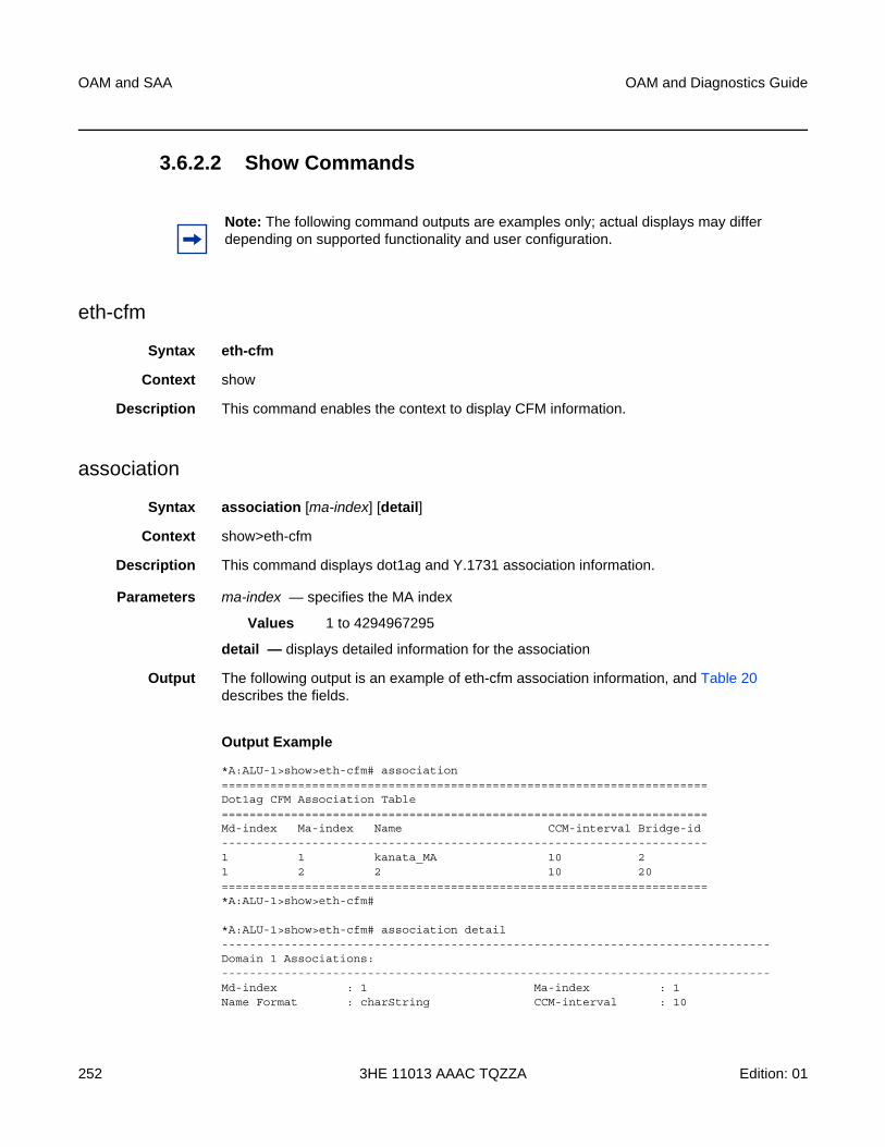
OAM and SAA
252
OAM and Diagnostics Guide
3HE 11013 AAAC TQZZA Edition: 01
3.6.2.2 Show Commands
eth-cfm
Syntax eth-cfm
Context show
Description This command enables the context to display CFM information.
association
Syntax association [ma-index] [detail]
Context show>eth-cfm
Description This command displays dot1ag and Y.1731 association information.
Parameters ma-index — specifies the MA index
Values 1 to 4294967295
detail — displays detailed information for the association
Output The following output is an example of eth-cfm association information, and Table 20 describes the fields.
Output Example
*A:ALU-1>show>eth-cfm# association======================================================================Dot1ag CFM Association Table======================================================================Md-index Ma-index Name CCM-interval Bridge-id----------------------------------------------------------------------1 1 kanata_MA 10 21 2 2 10 20======================================================================*A:ALU-1>show>eth-cfm#
*A:ALU-1>show>eth-cfm# association detail-------------------------------------------------------------------------------Domain 1 Associations:-------------------------------------------------------------------------------Md-index : 1 Ma-index : 1Name Format : charString CCM-interval : 10
Note: The following command outputs are examples only; actual displays may differ depending on supported functionality and user configuration.
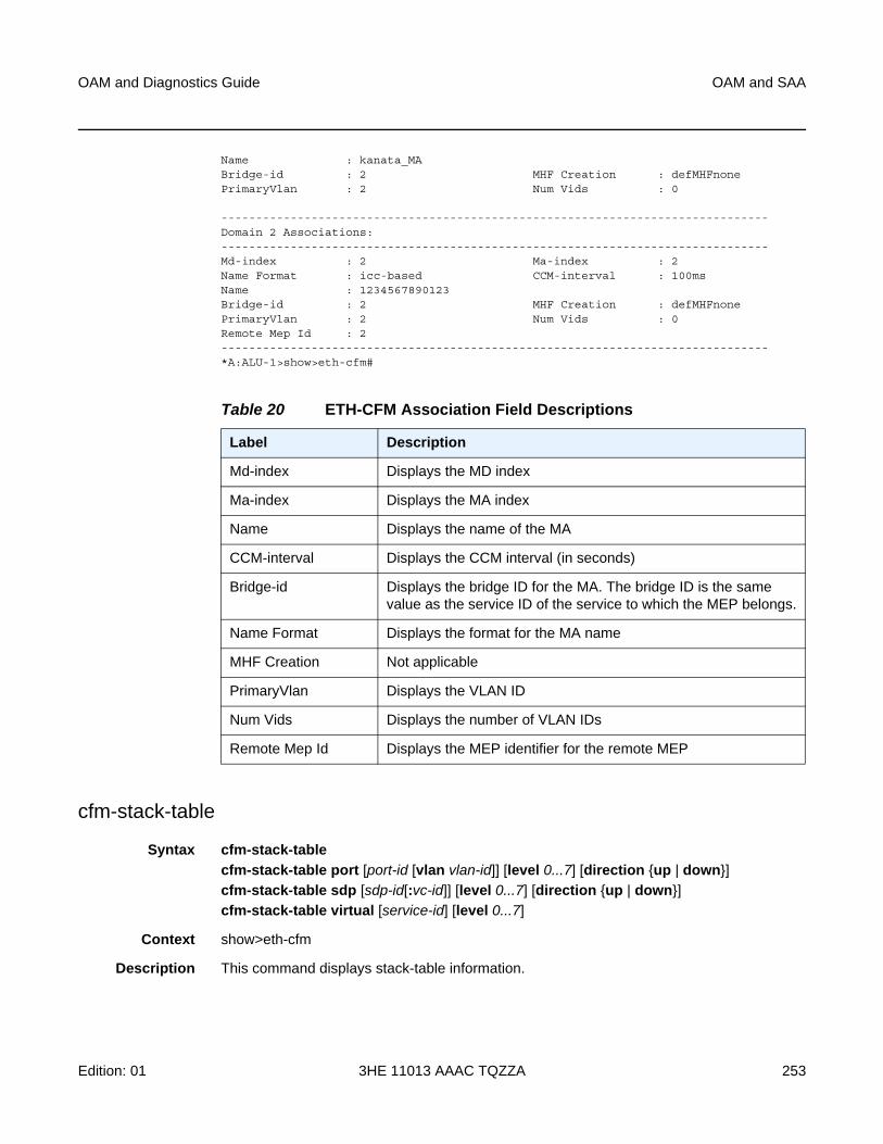
OAM and Diagnostics Guide OAM and SAA
Edition: 01 3HE 11013 AAAC TQZZA 253
Name : kanata_MABridge-id : 2 MHF Creation : defMHFnonePrimaryVlan : 2 Num Vids : 0
-------------------------------------------------------------------------------Domain 2 Associations:-------------------------------------------------------------------------------Md-index : 2 Ma-index : 2Name Format : icc-based CCM-interval : 100msName : 1234567890123Bridge-id : 2 MHF Creation : defMHFnonePrimaryVlan : 2 Num Vids : 0Remote Mep Id : 2-------------------------------------------------------------------------------*A:ALU-1>show>eth-cfm#
cfm-stack-table
Syntax cfm-stack-table
cfm-stack-table port [port-id [vlan vlan-id]] [level 0...7] [direction {up | down}]
cfm-stack-table sdp [sdp-id[:vc-id]] [level 0...7] [direction {up | down}]
cfm-stack-table virtual [service-id] [level 0...7]
Context show>eth-cfm
Description This command displays stack-table information.
Table 20 ETH-CFM Association Field Descriptions
Label Description
Md-index Displays the MD index
Ma-index Displays the MA index
Name Displays the name of the MA
CCM-interval Displays the CCM interval (in seconds)
Bridge-id Displays the bridge ID for the MA. The bridge ID is the same value as the service ID of the service to which the MEP belongs.
Name Format Displays the format for the MA name
MHF Creation Not applicable
PrimaryVlan Displays the VLAN ID
Num Vids Displays the number of VLAN IDs
Remote Mep Id Displays the MEP identifier for the remote MEP
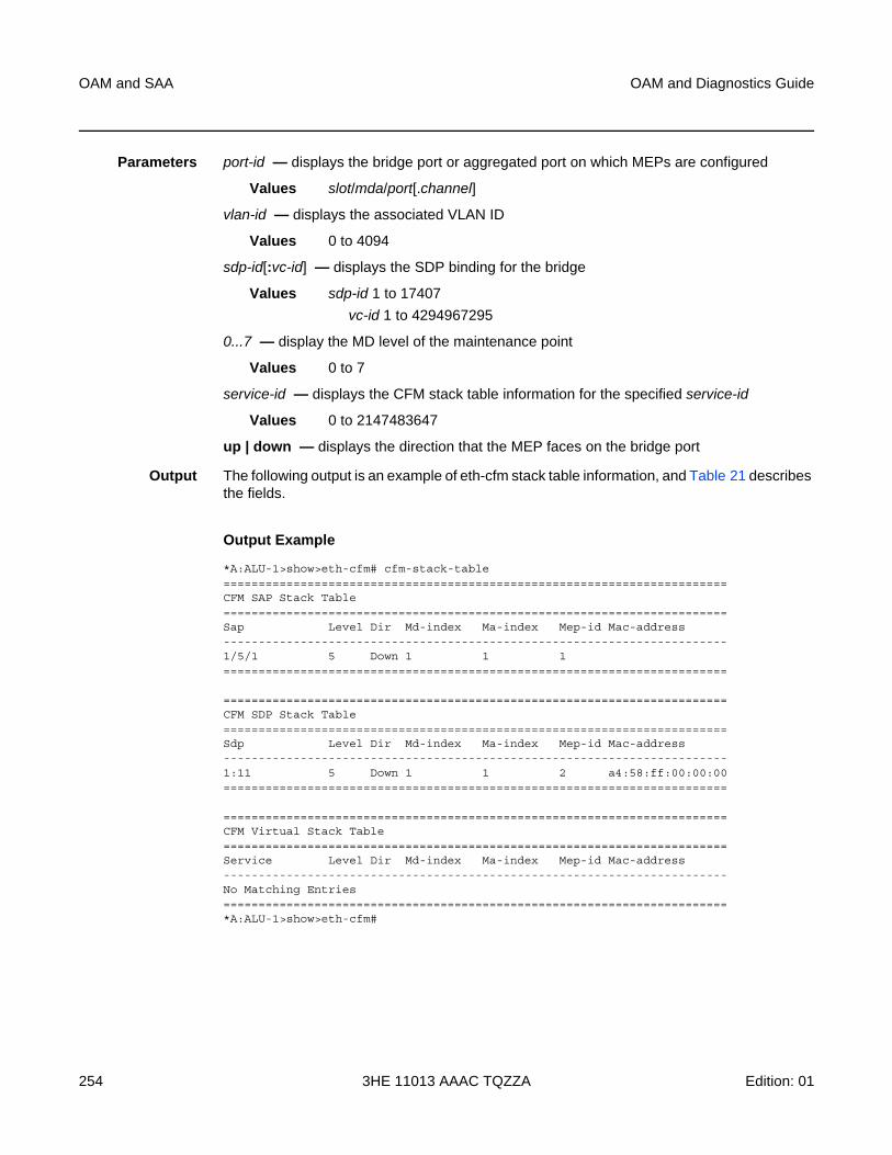
OAM and SAA
254
OAM and Diagnostics Guide
3HE 11013 AAAC TQZZA Edition: 01
Parameters port-id — displays the bridge port or aggregated port on which MEPs are configured
Values slot/mda/port[.channel]
vlan-id — displays the associated VLAN ID
Values 0 to 4094
sdp-id[:vc-id] — displays the SDP binding for the bridge
Values sdp-id 1 to 17407
vc-id 1 to 4294967295
0...7 — display the MD level of the maintenance point
Values 0 to 7
service-id — displays the CFM stack table information for the specified service-id
Values 0 to 2147483647
up | down — displays the direction that the MEP faces on the bridge port
Output The following output is an example of eth-cfm stack table information, and Table 21 describes the fields.
Output Example
*A:ALU-1>show>eth-cfm# cfm-stack-table========================================================================CFM SAP Stack Table========================================================================Sap Level Dir Md-index Ma-index Mep-id Mac-address------------------------------------------------------------------------1/5/1 5 Down 1 1 1========================================================================
========================================================================CFM SDP Stack Table========================================================================Sdp Level Dir Md-index Ma-index Mep-id Mac-address------------------------------------------------------------------------1:11 5 Down 1 1 2 a4:58:ff:00:00:00========================================================================
========================================================================CFM Virtual Stack Table========================================================================Service Level Dir Md-index Ma-index Mep-id Mac-address------------------------------------------------------------------------No Matching Entries========================================================================*A:ALU-1>show>eth-cfm#
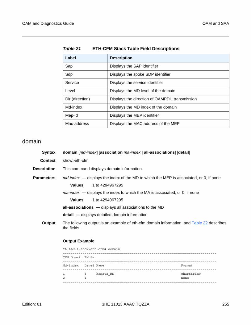
OAM and Diagnostics Guide OAM and SAA
Edition: 01 3HE 11013 AAAC TQZZA 255
domain
Syntax domain [md-index] [association ma-index | all-associations] [detail]
Context show>eth-cfm
Description This command displays domain information.
Parameters md-index — displays the index of the MD to which the MEP is associated, or 0, if none
Values 1 to 4294967295
ma-index — displays the index to which the MA is associated, or 0, if none
Values 1 to 4294967295
all-associations — displays all associations to the MD
detail — displays detailed domain information
Output The following output is an example of eth-cfm domain information, and Table 22 describes the fields.
Output Example
*A:ALU-1>show>eth-cfm# domain==============================================================================CFM Domain Table==============================================================================Md-index Level Name Format------------------------------------------------------------------------------1 5 kanata_MD charString2 1 none==============================================================================
Table 21 ETH-CFM Stack Table Field Descriptions
Label Description
Sap Displays the SAP identifier
Sdp Displays the spoke SDP identifier
Service Displays the service identifier
Level Displays the MD level of the domain
Dir (direction) Displays the direction of OAMPDU transmission
Md-index Displays the MD index of the domain
Mep-id Displays the MEP identifier
Mac-address Displays the MAC address of the MEP
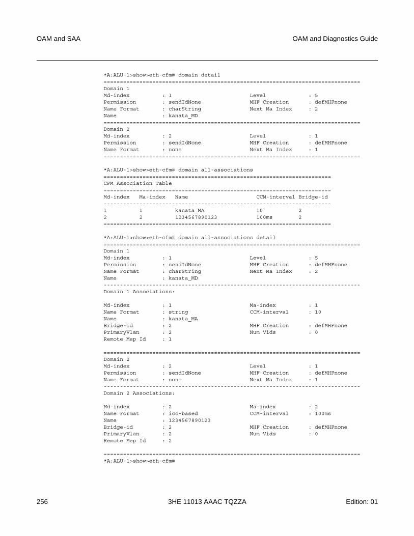
OAM and SAA
256
OAM and Diagnostics Guide
3HE 11013 AAAC TQZZA Edition: 01
*A:ALU-1>show>eth-cfm# domain detail===============================================================================Domain 1Md-index : 1 Level : 5Permission : sendIdNone MHF Creation : defMHFnoneName Format : charString Next Ma Index : 2Name : kanata_MD===============================================================================Domain 2Md-index : 2 Level : 1Permission : sendIdNone MHF Creation : defMHFnoneName Format : none Next Ma Index : 1===============================================================================
*A:ALU-1>show>eth-cfm# domain all-associations======================================================================CFM Association Table======================================================================Md-index Ma-index Name CCM-interval Bridge-id----------------------------------------------------------------------1 1 kanata_MA 10 22 2 1234567890123 100ms 2======================================================================
*A:ALU-1>show>eth-cfm# domain all-associations detail===============================================================================Domain 1Md-index : 1 Level : 5Permission : sendIdNone MHF Creation : defMHFnoneName Format : charString Next Ma Index : 2Name : kanata_MD-------------------------------------------------------------------------------Domain 1 Associations:
Md-index : 1 Ma-index : 1Name Format : string CCM-interval : 10Name : kanata_MABridge-id : 2 MHF Creation : defMHFnonePrimaryVlan : 2 Num Vids : 0Remote Mep Id : 1
===============================================================================Domain 2Md-index : 2 Level : 1Permission : sendIdNone MHF Creation : defMHFnoneName Format : none Next Ma Index : 1-------------------------------------------------------------------------------Domain 2 Associations:
Md-index : 2 Ma-index : 2Name Format : icc-based CCM-interval : 100msName : 1234567890123Bridge-id : 2 MHF Creation : defMHFnonePrimaryVlan : 2 Num Vids : 0Remote Mep Id : 2
===============================================================================*A:ALU-1>show>eth-cfm#
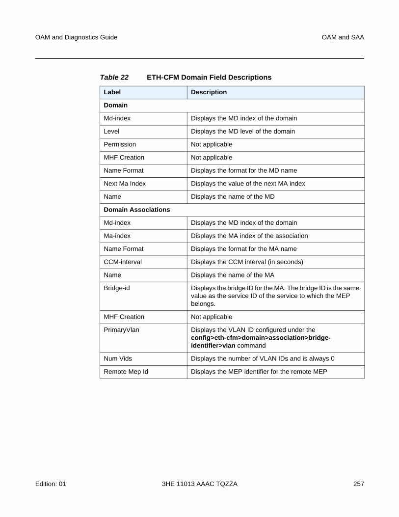
OAM and Diagnostics Guide OAM and SAA
Edition: 01 3HE 11013 AAAC TQZZA 257
Table 22 ETH-CFM Domain Field Descriptions
Label Description
Domain
Md-index Displays the MD index of the domain
Level Displays the MD level of the domain
Permission Not applicable
MHF Creation Not applicable
Name Format Displays the format for the MD name
Next Ma Index Displays the value of the next MA index
Name Displays the name of the MD
Domain Associations
Md-index Displays the MD index of the domain
Ma-index Displays the MA index of the association
Name Format Displays the format for the MA name
CCM-interval Displays the CCM interval (in seconds)
Name Displays the name of the MA
Bridge-id Displays the bridge ID for the MA. The bridge ID is the same value as the service ID of the service to which the MEP belongs.
MHF Creation Not applicable
PrimaryVlan Displays the VLAN ID configured under the config>eth-cfm>domain>association>bridge-identifier>vlan command
Num Vids Displays the number of VLAN IDs and is always 0
Remote Mep Id Displays the MEP identifier for the remote MEP
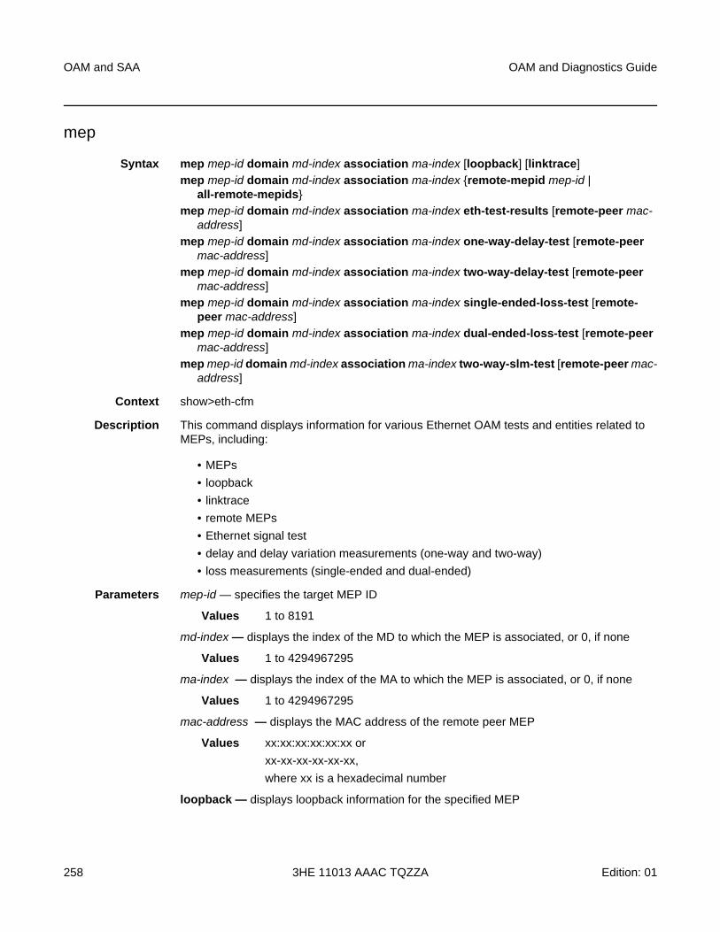
OAM and SAA
258
OAM and Diagnostics Guide
3HE 11013 AAAC TQZZA Edition: 01
mep
Syntax mep mep-id domain md-index association ma-index [loopback] [linktrace]
mep mep-id domain md-index association ma-index {remote-mepid mep-id | all-remote-mepids}
mep mep-id domain md-index association ma-index eth-test-results [remote-peer mac-address]
mep mep-id domain md-index association ma-index one-way-delay-test [remote-peer mac-address]
mep mep-id domain md-index association ma-index two-way-delay-test [remote-peer mac-address]
mep mep-id domain md-index association ma-index single-ended-loss-test [remote-peer mac-address]
mep mep-id domain md-index association ma-index dual-ended-loss-test [remote-peer mac-address]
mep mep-id domain md-index association ma-index two-way-slm-test [remote-peer mac-address]
Context show>eth-cfm
Description This command displays information for various Ethernet OAM tests and entities related to MEPs, including:
• MEPs
• loopback
• linktrace
• remote MEPs
• Ethernet signal test
• delay and delay variation measurements (one-way and two-way)
• loss measurements (single-ended and dual-ended)
Parameters mep-id — specifies the target MEP ID
Values 1 to 8191
md-index — displays the index of the MD to which the MEP is associated, or 0, if none
Values 1 to 4294967295
ma-index — displays the index of the MA to which the MEP is associated, or 0, if none
Values 1 to 4294967295
mac-address — displays the MAC address of the remote peer MEP
Values xx:xx:xx:xx:xx:xx or
xx-xx-xx-xx-xx-xx,
where xx is a hexadecimal number
loopback — displays loopback information for the specified MEP
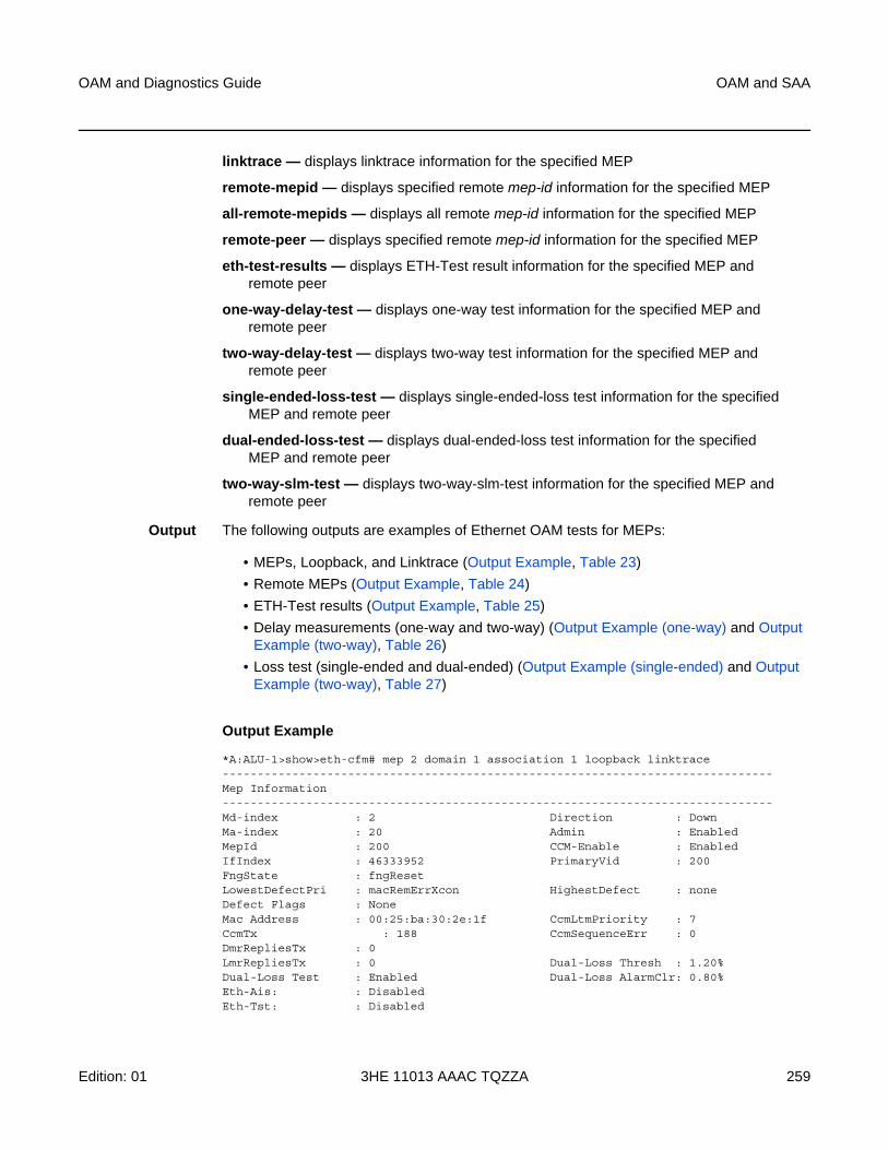
OAM and Diagnostics Guide OAM and SAA
Edition: 01 3HE 11013 AAAC TQZZA 259
linktrace — displays linktrace information for the specified MEP
remote-mepid — displays specified remote mep-id information for the specified MEP
all-remote-mepids — displays all remote mep-id information for the specified MEP
remote-peer — displays specified remote mep-id information for the specified MEP
eth-test-results — displays ETH-Test result information for the specified MEP and remote peer
one-way-delay-test — displays one-way test information for the specified MEP and remote peer
two-way-delay-test — displays two-way test information for the specified MEP and remote peer
single-ended-loss-test — displays single-ended-loss test information for the specified MEP and remote peer
dual-ended-loss-test — displays dual-ended-loss test information for the specified MEP and remote peer
two-way-slm-test — displays two-way-slm-test information for the specified MEP and remote peer
Output The following outputs are examples of Ethernet OAM tests for MEPs:
• MEPs, Loopback, and Linktrace (Output Example, Table 23)
• Remote MEPs (Output Example, Table 24)
• ETH-Test results (Output Example, Table 25)
• Delay measurements (one-way and two-way) (Output Example (one-way) and Output Example (two-way), Table 26)
• Loss test (single-ended and dual-ended) (Output Example (single-ended) and Output Example (two-way), Table 27)
Output Example
*A:ALU-1>show>eth-cfm# mep 2 domain 1 association 1 loopback linktrace-------------------------------------------------------------------------------Mep Information-------------------------------------------------------------------------------Md-index : 2 Direction : DownMa-index : 20 Admin : EnabledMepId : 200 CCM-Enable : EnabledIfIndex : 46333952 PrimaryVid : 200FngState : fngResetLowestDefectPri : macRemErrXcon HighestDefect : noneDefect Flags : NoneMac Address : 00:25:ba:30:2e:1f CcmLtmPriority : 7CcmTx : 188 CcmSequenceErr : 0DmrRepliesTx : 0LmrRepliesTx : 0 Dual-Loss Thresh : 1.20%Dual-Loss Test : Enabled Dual-Loss AlarmClr: 0.80%Eth-Ais: : DisabledEth-Tst: : Disabled
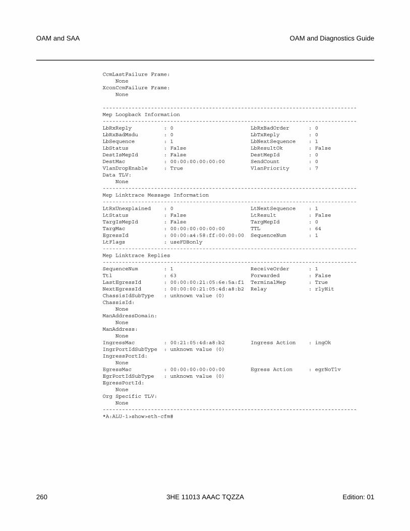
OAM and SAA
260
OAM and Diagnostics Guide
3HE 11013 AAAC TQZZA Edition: 01
CcmLastFailure Frame:None
XconCcmFailure Frame:None
-------------------------------------------------------------------------------Mep Loopback Information-------------------------------------------------------------------------------LbRxReply : 0 LbRxBadOrder : 0LbRxBadMsdu : 0 LbTxReply : 0LbSequence : 1 LbNextSequence : 1LbStatus : False LbResultOk : FalseDestIsMepId : False DestMepId : 0DestMac : 00:00:00:00:00:00 SendCount : 0VlanDropEnable : True VlanPriority : 7Data TLV:
None-------------------------------------------------------------------------------Mep Linktrace Message Information-------------------------------------------------------------------------------LtRxUnexplained : 0 LtNextSequence : 1LtStatus : False LtResult : FalseTargIsMepId : False TargMepId : 0TargMac : 00:00:00:00:00:00 TTL : 64EgressId : 00:00:a4:58:ff:00:00:00 SequenceNum : 1LtFlags : useFDBonly-------------------------------------------------------------------------------Mep Linktrace Replies-------------------------------------------------------------------------------SequenceNum : 1 ReceiveOrder : 1Ttl : 63 Forwarded : FalseLastEgressId : 00:00:00:21:05:6e:5a:f1 TerminalMep : TrueNextEgressId : 00:00:00:21:05:4d:a8:b2 Relay : rlyHitChassisIdSubType : unknown value (0)ChassisId:
NoneManAddressDomain:
NoneManAddress:
NoneIngressMac : 00:21:05:4d:a8:b2 Ingress Action : ingOkIngrPortIdSubType : unknown value (0)IngressPortId:
NoneEgressMac : 00:00:00:00:00:00 Egress Action : egrNoTlvEgrPortIdSubType : unknown value (0)EgressPortId:
NoneOrg Specific TLV:
None-------------------------------------------------------------------------------*A:ALU-1>show>eth-cfm#
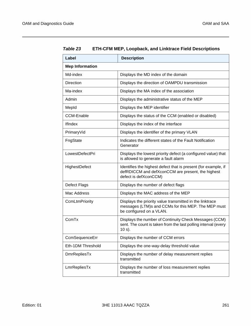
OAM and Diagnostics Guide OAM and SAA
Edition: 01 3HE 11013 AAAC TQZZA 261
Table 23 ETH-CFM MEP, Loopback, and Linktrace Field Descriptions
Label Description
Mep Information
Md-index Displays the MD index of the domain
Direction Displays the direction of OAMPDU transmission
Ma-index Displays the MA index of the association
Admin Displays the administrative status of the MEP
MepId Displays the MEP identifier
CCM-Enable Displays the status of the CCM (enabled or disabled)
IfIndex Displays the index of the interface
PrimaryVid Displays the identifier of the primary VLAN
FngState Indicates the different states of the Fault Notification Generator
LowestDefectPri Displays the lowest priority defect (a configured value) that is allowed to generate a fault alarm
HighestDefect Identifies the highest defect that is present (for example, if defRDICCM and defXconCCM are present, the highest defect is defXconCCM)
Defect Flags Displays the number of defect flags
Mac Address Displays the MAC address of the MEP
CcmLtmPriority Displays the priority value transmitted in the linktrace messages (LTM)s and CCMs for this MEP. The MEP must be configured on a VLAN.
CcmTx Displays the number of Continuity Check Messages (CCM) sent. The count is taken from the last polling interval (every 10 s).
CcmSequenceErr Displays the number of CCM errors
Eth-1DM Threshold Displays the one-way-delay threshold value
DmrRepliesTx Displays the number of delay measurement replies transmitted
LmrRepliesTx Displays the number of loss measurement replies transmitted
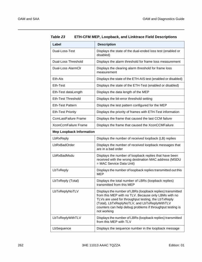
OAM and SAA
262
OAM and Diagnostics Guide
3HE 11013 AAAC TQZZA Edition: 01
Dual-Loss-Test Displays the state of the dual-ended loss test (enabled or disabled)
Dual-Loss Threshold Displays the alarm threshold for frame loss measurement
Dual-Loss AlarmClr Displays the clearing alarm threshold for frame loss measurement
Eth-Ais Displays the state of the ETH-AIS test (enabled or disabled)
Eth-Test Displays the state of the ETH-Test (enabled or disabled)
Eth-Test dataLength Displays the data length of the MEP
Eth-Test Threshold Displays the bit-error threshold setting
Eth-Test Pattern Displays the test pattern configured for the MEP
Eth-Test Priority Displays the priority of frames with ETH-Test information
CcmLastFailure Frame Displays the frame that caused the last CCM failure
XconCcmFailure Frame Displays the frame that caused the XconCCMFailure
Mep Loopback Information
LbRxReply Displays the number of received loopback (LB) replies
LbRxBadOrder Displays the number of received loopback messages that are in a bad order
LbRxBadMsdu Displays the number of loopback replies that have been received with the wrong destination MAC address (MSDU = MAC Service Data Unit)
LbTxReply Displays the number of loopback replies transmitted out this MEP
LbTxReply (Total) Displays the total number of LBRs (loopback replies) transmitted from this MEP
LbTxReplyNoTLV Displays the number of LBRs (loopback replies) transmitted from this MEP with no TLV. Because only LBMs with no TLVs are used for throughput testing, the LbTxReply (Total), LbTxReplyNoTLV, and LbTxReplyWithTLV counters can help debug problems if throughput testing is not working
LbTxReplyWithTLV Displays the number of LBRs (loopback replies) transmitted from this MEP with TLV
LbSequence Displays the sequence number in the loopback message
Table 23 ETH-CFM MEP, Loopback, and Linktrace Field Descriptions
Label Description
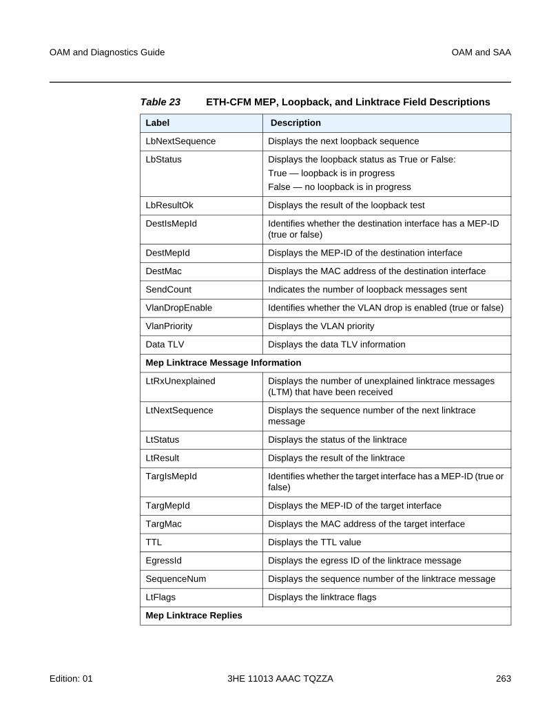
OAM and Diagnostics Guide OAM and SAA
Edition: 01 3HE 11013 AAAC TQZZA 263
LbNextSequence Displays the next loopback sequence
LbStatus Displays the loopback status as True or False:
True — loopback is in progress
False — no loopback is in progress
LbResultOk Displays the result of the loopback test
DestIsMepId Identifies whether the destination interface has a MEP-ID (true or false)
DestMepId Displays the MEP-ID of the destination interface
DestMac Displays the MAC address of the destination interface
SendCount Indicates the number of loopback messages sent
VlanDropEnable Identifies whether the VLAN drop is enabled (true or false)
VlanPriority Displays the VLAN priority
Data TLV Displays the data TLV information
Mep Linktrace Message Information
LtRxUnexplained Displays the number of unexplained linktrace messages (LTM) that have been received
LtNextSequence Displays the sequence number of the next linktrace message
LtStatus Displays the status of the linktrace
LtResult Displays the result of the linktrace
TargIsMepId Identifies whether the target interface has a MEP-ID (true or false)
TargMepId Displays the MEP-ID of the target interface
TargMac Displays the MAC address of the target interface
TTL Displays the TTL value
EgressId Displays the egress ID of the linktrace message
SequenceNum Displays the sequence number of the linktrace message
LtFlags Displays the linktrace flags
Mep Linktrace Replies
Table 23 ETH-CFM MEP, Loopback, and Linktrace Field Descriptions
Label Description
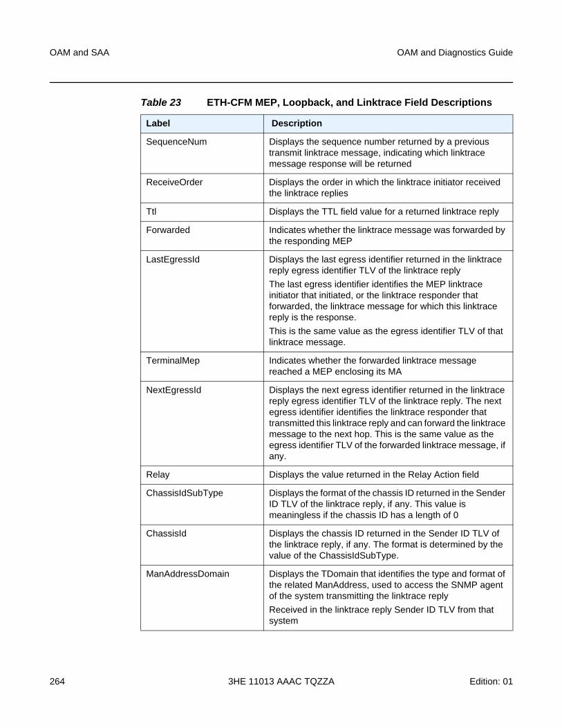
OAM and SAA
264
OAM and Diagnostics Guide
3HE 11013 AAAC TQZZA Edition: 01
SequenceNum Displays the sequence number returned by a previous transmit linktrace message, indicating which linktrace message response will be returned
ReceiveOrder Displays the order in which the linktrace initiator received the linktrace replies
Ttl Displays the TTL field value for a returned linktrace reply
Forwarded Indicates whether the linktrace message was forwarded by the responding MEP
LastEgressId Displays the last egress identifier returned in the linktrace reply egress identifier TLV of the linktrace reply
The last egress identifier identifies the MEP linktrace initiator that initiated, or the linktrace responder that forwarded, the linktrace message for which this linktrace reply is the response.
This is the same value as the egress identifier TLV of that linktrace message.
TerminalMep Indicates whether the forwarded linktrace message reached a MEP enclosing its MA
NextEgressId Displays the next egress identifier returned in the linktrace reply egress identifier TLV of the linktrace reply. The next egress identifier identifies the linktrace responder that transmitted this linktrace reply and can forward the linktrace message to the next hop. This is the same value as the egress identifier TLV of the forwarded linktrace message, if any.
Relay Displays the value returned in the Relay Action field
ChassisIdSubType Displays the format of the chassis ID returned in the Sender ID TLV of the linktrace reply, if any. This value is meaningless if the chassis ID has a length of 0
ChassisId Displays the chassis ID returned in the Sender ID TLV of the linktrace reply, if any. The format is determined by the value of the ChassisIdSubType.
ManAddressDomain Displays the TDomain that identifies the type and format of the related ManAddress, used to access the SNMP agent of the system transmitting the linktrace reply
Received in the linktrace reply Sender ID TLV from that system
Table 23 ETH-CFM MEP, Loopback, and Linktrace Field Descriptions
Label Description
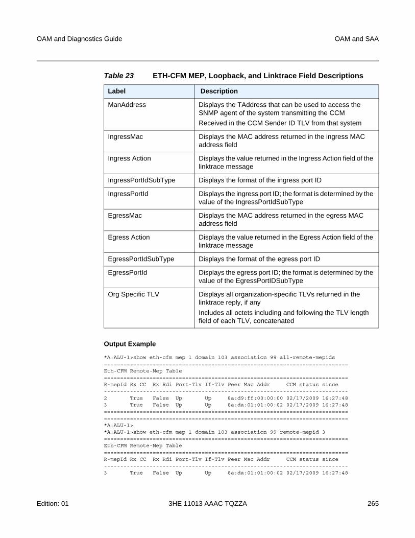
OAM and Diagnostics Guide OAM and SAA
Edition: 01 3HE 11013 AAAC TQZZA 265
Output Example
*A:ALU-1>show eth-cfm mep 1 domain 103 association 99 all-remote-mepids===========================================================================Eth-CFM Remote-Mep Table===========================================================================R-mepId Rx CC Rx Rdi Port-Tlv If-Tlv Peer Mac Addr CCM status since---------------------------------------------------------------------------2 True False Up Up 8a:d9:ff:00:00:00 02/17/2009 16:27:483 True False Up Up 8a:da:01:01:00:02 02/17/2009 16:27:48======================================================================================================================================================*A:ALU-1>*A:ALU-1>show eth-cfm mep 1 domain 103 association 99 remote-mepid 3===========================================================================Eth-CFM Remote-Mep Table===========================================================================R-mepId Rx CC Rx Rdi Port-Tlv If-Tlv Peer Mac Addr CCM status since---------------------------------------------------------------------------3 True False Up Up 8a:da:01:01:00:02 02/17/2009 16:27:48
ManAddress Displays the TAddress that can be used to access the SNMP agent of the system transmitting the CCM
Received in the CCM Sender ID TLV from that system
IngressMac Displays the MAC address returned in the ingress MAC address field
Ingress Action Displays the value returned in the Ingress Action field of the linktrace message
IngressPortIdSubType Displays the format of the ingress port ID
IngressPortId Displays the ingress port ID; the format is determined by the value of the IngressPortIdSubType
EgressMac Displays the MAC address returned in the egress MAC address field
Egress Action Displays the value returned in the Egress Action field of the linktrace message
EgressPortIdSubType Displays the format of the egress port ID
EgressPortId Displays the egress port ID; the format is determined by the value of the EgressPortIDSubType
Org Specific TLV Displays all organization-specific TLVs returned in the linktrace reply, if any
Includes all octets including and following the TLV length field of each TLV, concatenated
Table 23 ETH-CFM MEP, Loopback, and Linktrace Field Descriptions
Label Description
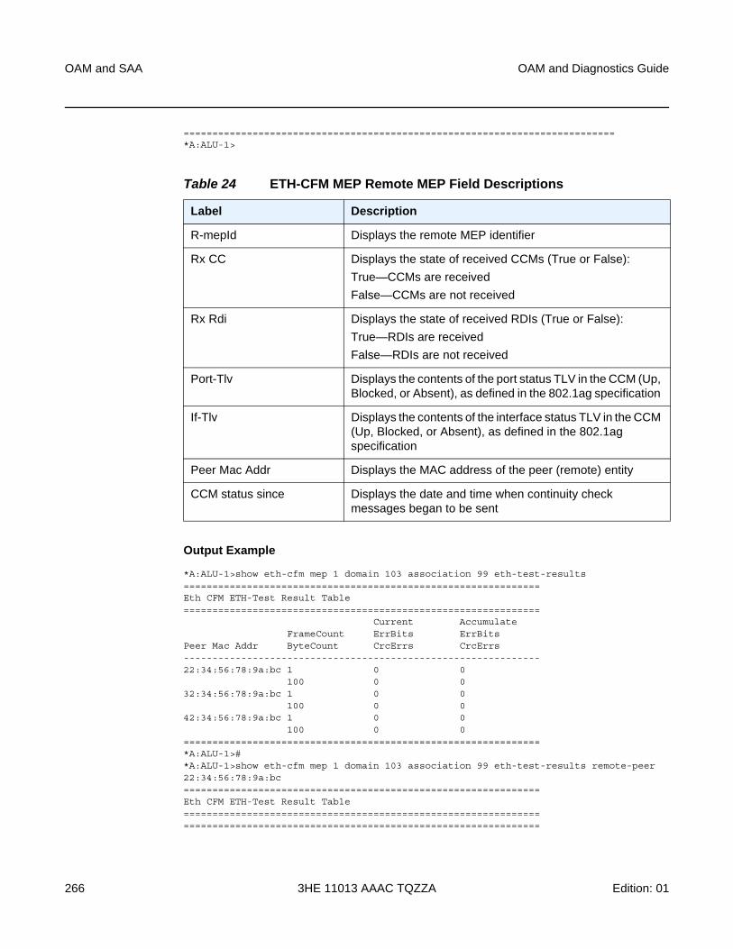
OAM and SAA
266
OAM and Diagnostics Guide
3HE 11013 AAAC TQZZA Edition: 01
===========================================================================*A:ALU-1>
Output Example
*A:ALU-1>show eth-cfm mep 1 domain 103 association 99 eth-test-results==============================================================Eth CFM ETH-Test Result Table==============================================================
Current AccumulateFrameCount ErrBits ErrBits
Peer Mac Addr ByteCount CrcErrs CrcErrs--------------------------------------------------------------22:34:56:78:9a:bc 1 0 0
100 0 032:34:56:78:9a:bc 1 0 0
100 0 042:34:56:78:9a:bc 1 0 0
100 0 0==============================================================*A:ALU-1>#*A:ALU-1>show eth-cfm mep 1 domain 103 association 99 eth-test-results remote-peer22:34:56:78:9a:bc==============================================================Eth CFM ETH-Test Result Table============================================================================================================================
Table 24 ETH-CFM MEP Remote MEP Field Descriptions
Label Description
R-mepId Displays the remote MEP identifier
Rx CC Displays the state of received CCMs (True or False):
True—CCMs are received
False—CCMs are not received
Rx Rdi Displays the state of received RDIs (True or False):
True—RDIs are received
False—RDIs are not received
Port-Tlv Displays the contents of the port status TLV in the CCM (Up, Blocked, or Absent), as defined in the 802.1ag specification
If-Tlv Displays the contents of the interface status TLV in the CCM (Up, Blocked, or Absent), as defined in the 802.1ag specification
Peer Mac Addr Displays the MAC address of the peer (remote) entity
CCM status since Displays the date and time when continuity check messages began to be sent
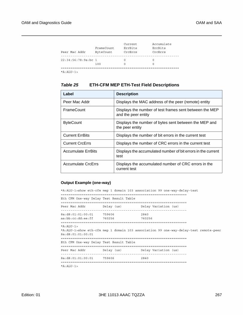
OAM and Diagnostics Guide OAM and SAA
Edition: 01 3HE 11013 AAAC TQZZA 267
Current AccumulateFrameCount ErrBits ErrBits
Peer Mac Addr ByteCount CrcErrs CrcErrs--------------------------------------------------------------22:34:56:78:9a:bc 1 0 0
100 0 0==============================================================*A:ALU-1>
Output Example (one-way)
*A:ALU-1>show eth-cfm mep 1 domain 103 association 99 one-way-delay-test==================================================================Eth CFM One-way Delay Test Result Table==================================================================Peer Mac Addr Delay (us) Delay Variation (us)------------------------------------------------------------------8a:d8:01:01:00:01 759606 2840aa:bb:cc:dd:ee:ff 760256 760256==================================================================*A:ALU-1>*A:ALU-1>show eth-cfm mep 1 domain 103 association 99 one-way-delay-test remote-peer8a:d8:01:01:00:01==================================================================Eth CFM One-way Delay Test Result Table==================================================================Peer Mac Addr Delay (us) Delay Variation (us)------------------------------------------------------------------8a:d8:01:01:00:01 759606 2840==================================================================*A:ALU-1>
Table 25 ETH-CFM MEP ETH-Test Field Descriptions
Label Description
Peer Mac Addr Displays the MAC address of the peer (remote) entity
FrameCount Displays the number of test frames sent between the MEP and the peer entity
ByteCount Displays the number of bytes sent between the MEP and the peer entity
Current ErrBits Displays the number of bit errors in the current test
Current CrcErrs Displays the number of CRC errors in the current test
Accumulate ErrBits Displays the accumulated number of bit errors in the current test
Accumulate CrcErrs Displays the accumulated number of CRC errors in the current test
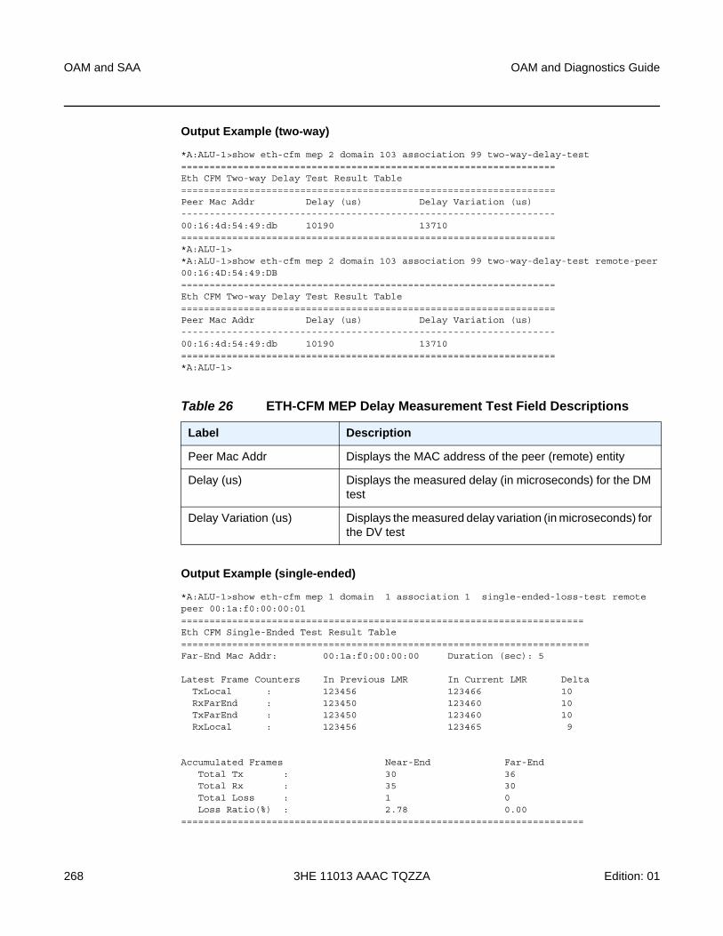
OAM and SAA
268
OAM and Diagnostics Guide
3HE 11013 AAAC TQZZA Edition: 01
Output Example (two-way)
*A:ALU-1>show eth-cfm mep 2 domain 103 association 99 two-way-delay-test==================================================================Eth CFM Two-way Delay Test Result Table==================================================================Peer Mac Addr Delay (us) Delay Variation (us)------------------------------------------------------------------00:16:4d:54:49:db 10190 13710==================================================================*A:ALU-1>*A:ALU-1>show eth-cfm mep 2 domain 103 association 99 two-way-delay-test remote-peer00:16:4D:54:49:DB==================================================================Eth CFM Two-way Delay Test Result Table==================================================================Peer Mac Addr Delay (us) Delay Variation (us)------------------------------------------------------------------00:16:4d:54:49:db 10190 13710==================================================================*A:ALU-1>
Output Example (single-ended)
*A:ALU-1>show eth-cfm mep 1 domain 1 association 1 single-ended-loss-test remotepeer 00:1a:f0:00:00:01=======================================================================Eth CFM Single-Ended Test Result Table========================================================================Far-End Mac Addr: 00:1a:f0:00:00:00 Duration (sec): 5
Latest Frame Counters In Previous LMR In Current LMR DeltaTxLocal : 123456 123466 10RxFarEnd : 123450 123460 10TxFarEnd : 123450 123460 10RxLocal : 123456 123465 9
Accumulated Frames Near-End Far-EndTotal Tx : 30 36Total Rx : 35 30Total Loss : 1 0Loss Ratio(%) : 2.78 0.00
=======================================================================
Table 26 ETH-CFM MEP Delay Measurement Test Field Descriptions
Label Description
Peer Mac Addr Displays the MAC address of the peer (remote) entity
Delay (us) Displays the measured delay (in microseconds) for the DM test
Delay Variation (us) Displays the measured delay variation (in microseconds) for the DV test
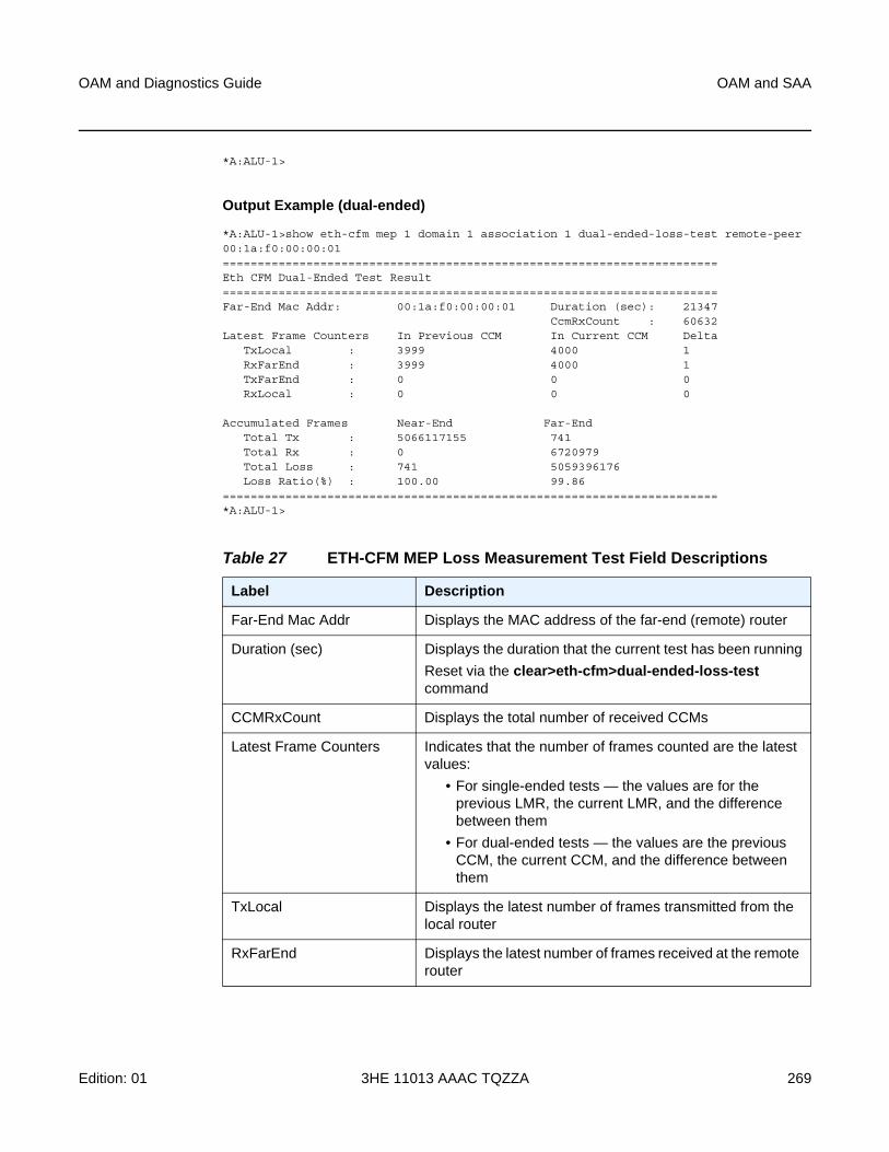
OAM and Diagnostics Guide OAM and SAA
Edition: 01 3HE 11013 AAAC TQZZA 269
*A:ALU-1>
Output Example (dual-ended)
*A:ALU-1>show eth-cfm mep 1 domain 1 association 1 dual-ended-loss-test remote-peer00:1a:f0:00:00:01=======================================================================Eth CFM Dual-Ended Test Result=======================================================================Far-End Mac Addr: 00:1a:f0:00:00:01 Duration (sec): 21347
CcmRxCount : 60632Latest Frame Counters In Previous CCM In Current CCM Delta
TxLocal : 3999 4000 1RxFarEnd : 3999 4000 1TxFarEnd : 0 0 0RxLocal : 0 0 0
Accumulated Frames Near-End Far-EndTotal Tx : 5066117155 741Total Rx : 0 6720979Total Loss : 741 5059396176Loss Ratio(%) : 100.00 99.86
=======================================================================*A:ALU-1>
Table 27 ETH-CFM MEP Loss Measurement Test Field Descriptions
Label Description
Far-End Mac Addr Displays the MAC address of the far-end (remote) router
Duration (sec) Displays the duration that the current test has been running
Reset via the clear>eth-cfm>dual-ended-loss-test command
CCMRxCount Displays the total number of received CCMs
Latest Frame Counters Indicates that the number of frames counted are the latest values:
• For single-ended tests — the values are for the previous LMR, the current LMR, and the difference between them
• For dual-ended tests — the values are the previous CCM, the current CCM, and the difference between them
TxLocal Displays the latest number of frames transmitted from the local router
RxFarEnd Displays the latest number of frames received at the remote router
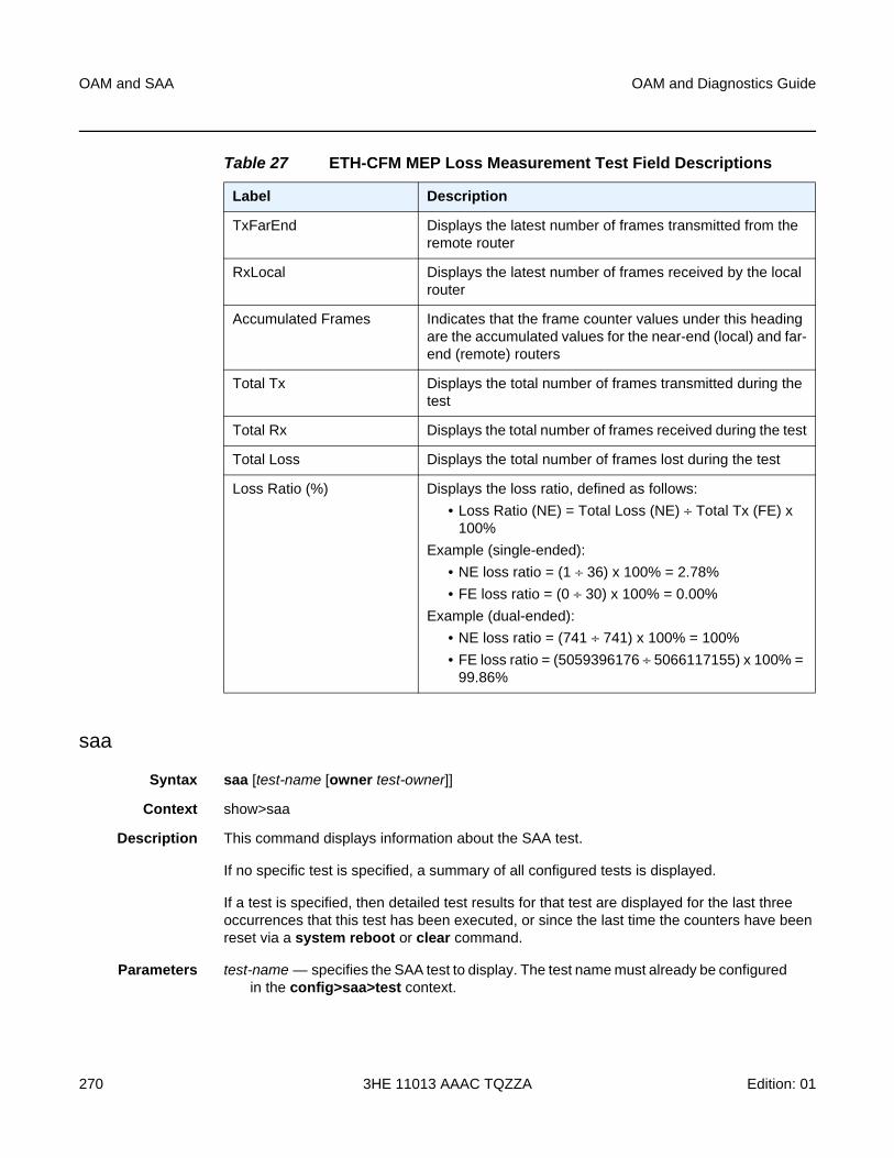
OAM and SAA
270
OAM and Diagnostics Guide
3HE 11013 AAAC TQZZA Edition: 01
saa
Syntax saa [test-name [owner test-owner]]
Context show>saa
Description This command displays information about the SAA test.
If no specific test is specified, a summary of all configured tests is displayed.
If a test is specified, then detailed test results for that test are displayed for the last three occurrences that this test has been executed, or since the last time the counters have been reset via a system reboot or clear command.
Parameters test-name — specifies the SAA test to display. The test name must already be configured in the config>saa>test context.
TxFarEnd Displays the latest number of frames transmitted from the remote router
RxLocal Displays the latest number of frames received by the local router
Accumulated Frames Indicates that the frame counter values under this heading are the accumulated values for the near-end (local) and far-end (remote) routers
Total Tx Displays the total number of frames transmitted during the test
Total Rx Displays the total number of frames received during the test
Total Loss Displays the total number of frames lost during the test
Loss Ratio (%) Displays the loss ratio, defined as follows:
• Loss Ratio (NE) = Total Loss (NE) ÷ Total Tx (FE) x 100%
Example (single-ended):
• NE loss ratio = (1 ÷ 36) x 100% = 2.78%
• FE loss ratio = (0 ÷ 30) x 100% = 0.00%
Example (dual-ended):
• NE loss ratio = (741 ÷ 741) x 100% = 100%
• FE loss ratio = (5059396176 ÷ 5066117155) x 100% = 99.86%
Table 27 ETH-CFM MEP Loss Measurement Test Field Descriptions
Label Description
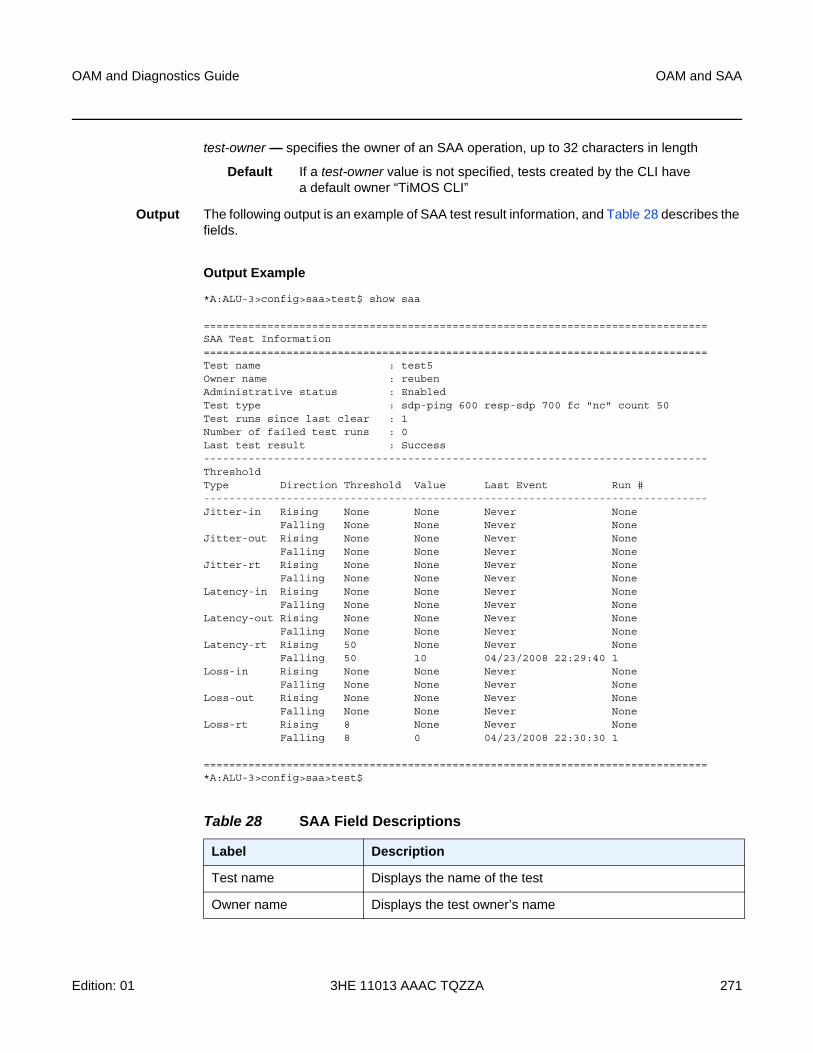
OAM and Diagnostics Guide OAM and SAA
Edition: 01 3HE 11013 AAAC TQZZA 271
test-owner — specifies the owner of an SAA operation, up to 32 characters in length
Default If a test-owner value is not specified, tests created by the CLI have a default owner “TiMOS CLI”
Output The following output is an example of SAA test result information, and Table 28 describes the fields.
Output Example
*A:ALU-3>config>saa>test$ show saa
===============================================================================SAA Test Information===============================================================================Test name : test5Owner name : reubenAdministrative status : EnabledTest type : sdp-ping 600 resp-sdp 700 fc "nc" count 50Test runs since last clear : 1Number of failed test runs : 0Last test result : Success-------------------------------------------------------------------------------ThresholdType Direction Threshold Value Last Event Run #-------------------------------------------------------------------------------Jitter-in Rising None None Never None
Falling None None Never NoneJitter-out Rising None None Never None
Falling None None Never NoneJitter-rt Rising None None Never None
Falling None None Never NoneLatency-in Rising None None Never None
Falling None None Never NoneLatency-out Rising None None Never None
Falling None None Never NoneLatency-rt Rising 50 None Never None
Falling 50 10 04/23/2008 22:29:40 1Loss-in Rising None None Never None
Falling None None Never NoneLoss-out Rising None None Never None
Falling None None Never NoneLoss-rt Rising 8 None Never None
Falling 8 0 04/23/2008 22:30:30 1
===============================================================================*A:ALU-3>config>saa>test$
Table 28 SAA Field Descriptions
Label Description
Test name Displays the name of the test
Owner name Displays the test owner’s name
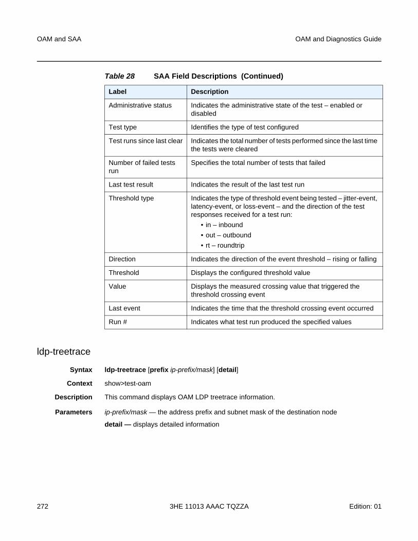
OAM and SAA
272
OAM and Diagnostics Guide
3HE 11013 AAAC TQZZA Edition: 01
ldp-treetrace
Syntax ldp-treetrace [prefix ip-prefix/mask] [detail]
Context show>test-oam
Description This command displays OAM LDP treetrace information.
Parameters ip-prefix/mask — the address prefix and subnet mask of the destination node
detail — displays detailed information
Administrative status Indicates the administrative state of the test – enabled or disabled
Test type Identifies the type of test configured
Test runs since last clear Indicates the total number of tests performed since the last time the tests were cleared
Number of failed tests run
Specifies the total number of tests that failed
Last test result Indicates the result of the last test run
Threshold type Indicates the type of threshold event being tested – jitter-event, latency-event, or loss-event – and the direction of the test responses received for a test run:
• in – inbound
• out – outbound
• rt – roundtrip
Direction Indicates the direction of the event threshold – rising or falling
Threshold Displays the configured threshold value
Value Displays the measured crossing value that triggered the threshold crossing event
Last event Indicates the time that the threshold crossing event occurred
Run # Indicates what test run produced the specified values
Table 28 SAA Field Descriptions (Continued)
Label Description
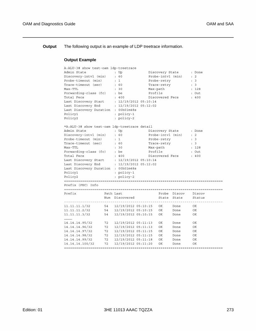
OAM and Diagnostics Guide OAM and SAA
Edition: 01 3HE 11013 AAAC TQZZA 273
Output The following output is an example of LDP treetrace information.
Output Example
A:ALU-3# show test-oam ldp-treetraceAdmin State : Up Discovery State : DoneDiscovery-intvl (min) : 60 Probe-intvl (min) : 2Probe-timeout (min) : 1 Probe-retry : 3Trace-timeout (sec) : 60 Trace-retry : 3Max-TTL : 30 Max-path : 128Forwarding-class (fc) : be Profile : OutTotal Fecs : 400 Discovered Fecs : 400Last Discovery Start : 12/19/2012 05:10:14Last Discovery End : 12/19/2012 05:12:02Last Discovery Duration : 00h01m48sPolicy1 : policy-1Policy2 : policy-2
*A:ALU-3# show test-oam ldp-treetrace detailAdmin State : Up Discovery State : DoneDiscovery-intvl (min) : 60 Probe-intvl (min) : 2Probe-timeout (min) : 1 Probe-retry : 3Trace-timeout (sec) : 60 Trace-retry : 3Max-TTL : 30 Max-path : 128Forwarding-class (fc) : be Profile : OutTotal Fecs : 400 Discovered Fecs : 400Last Discovery Start : 12/19/2012 05:10:14Last Discovery End : 12/19/2012 05:12:02Last Discovery Duration : 00h01m48sPolicy1 : policy-1Policy2 : policy-2===============================================================================Prefix (FEC) Info===============================================================================Prefix Path Last Probe Discov Discov
Num Discovered State State Status-------------------------------------------------------------------------------11.11.11.1/32 54 12/19/2012 05:10:15 OK Done OK11.11.11.2/32 54 12/19/2012 05:10:15 OK Done OK11.11.11.3/32 54 12/19/2012 05:10:15 OK Done OK…………14.14.14.95/32 72 12/19/2012 05:11:13 OK Done OK14.14.14.96/32 72 12/19/2012 05:11:13 OK Done OK14.14.14.97/32 72 12/19/2012 05:11:15 OK Done OK14.14.14.98/32 72 12/19/2012 05:11:15 OK Done OK14.14.14.99/32 72 12/19/2012 05:11:18 OK Done OK14.14.14.100/32 72 12/19/2012 05:11:20 OK Done OK===============================================================================
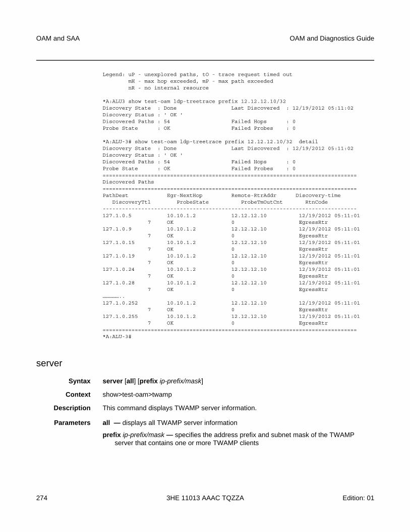
OAM and SAA
274
OAM and Diagnostics Guide
3HE 11013 AAAC TQZZA Edition: 01
Legend: uP - unexplored paths, tO - trace request timed outmH - max hop exceeded, mP - max path exceedednR - no internal resource
*A:ALU3 show test-oam ldp-treetrace prefix 12.12.12.10/32Discovery State : Done Last Discovered : 12/19/2012 05:11:02Discovery Status : ' OK 'Discovered Paths : 54 Failed Hops : 0Probe State : OK Failed Probes : 0
*A:ALU-3# show test-oam ldp-treetrace prefix 12.12.12.10/32 detailDiscovery State : Done Last Discovered : 12/19/2012 05:11:02Discovery Status : ' OK 'Discovered Paths : 54 Failed Hops : 0Probe State : OK Failed Probes : 0===============================================================================Discovered Paths===============================================================================PathDest Egr-NextHop Remote-RtrAddr Discovery-time
DiscoveryTtl ProbeState ProbeTmOutCnt RtnCode-------------------------------------------------------------------------------127.1.0.5 10.10.1.2 12.12.12.10 12/19/2012 05:11:01
7 OK 0 EgressRtr127.1.0.9 10.10.1.2 12.12.12.10 12/19/2012 05:11:01
7 OK 0 EgressRtr127.1.0.15 10.10.1.2 12.12.12.10 12/19/2012 05:11:01
7 OK 0 EgressRtr127.1.0.19 10.10.1.2 12.12.12.10 12/19/2012 05:11:01
7 OK 0 EgressRtr127.1.0.24 10.10.1.2 12.12.12.10 12/19/2012 05:11:01
7 OK 0 EgressRtr127.1.0.28 10.10.1.2 12.12.12.10 12/19/2012 05:11:01
7 OK 0 EgressRtr……………..127.1.0.252 10.10.1.2 12.12.12.10 12/19/2012 05:11:01
7 OK 0 EgressRtr127.1.0.255 10.10.1.2 12.12.12.10 12/19/2012 05:11:01
7 OK 0 EgressRtr===============================================================================*A:ALU-3#
server
Syntax server [all] [prefix ip-prefix/mask]
Context show>test-oam>twamp
Description This command displays TWAMP server information.
Parameters all — displays all TWAMP server information
prefix ip-prefix/mask — specifies the address prefix and subnet mask of the TWAMP server that contains one or more TWAMP clients
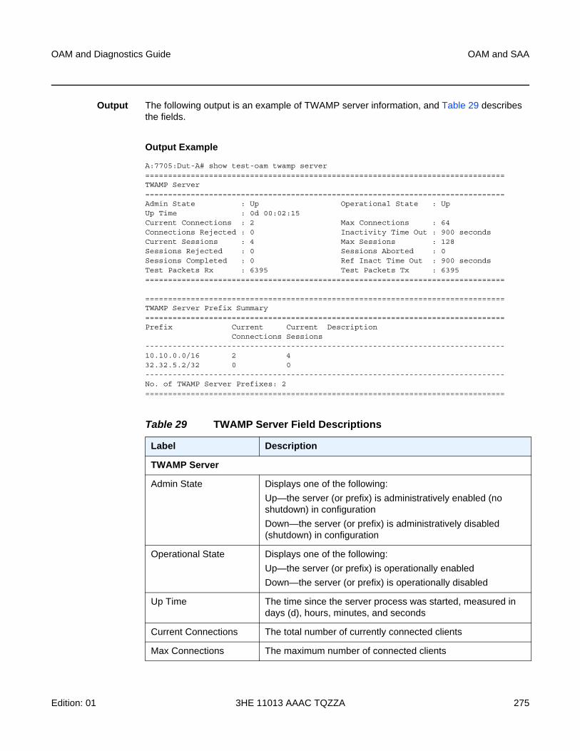
OAM and Diagnostics Guide OAM and SAA
Edition: 01 3HE 11013 AAAC TQZZA 275
Output The following output is an example of TWAMP server information, and Table 29 describes the fields.
Output Example
A:7705:Dut-A# show test-oam twamp server===============================================================================TWAMP Server===============================================================================Admin State : Up Operational State : UpUp Time : 0d 00:02:15Current Connections : 2 Max Connections : 64Connections Rejected : 0 Inactivity Time Out : 900 secondsCurrent Sessions : 4 Max Sessions : 128Sessions Rejected : 0 Sessions Aborted : 0Sessions Completed : 0 Ref Inact Time Out : 900 secondsTest Packets Rx : 6395 Test Packets Tx : 6395===============================================================================
===============================================================================TWAMP Server Prefix Summary===============================================================================Prefix Current Current Description
Connections Sessions-------------------------------------------------------------------------------10.10.0.0/16 2 432.32.5.2/32 0 0-------------------------------------------------------------------------------No. of TWAMP Server Prefixes: 2===============================================================================
Table 29 TWAMP Server Field Descriptions
Label Description
TWAMP Server
Admin State Displays one of the following:
Up—the server (or prefix) is administratively enabled (no shutdown) in configuration
Down—the server (or prefix) is administratively disabled (shutdown) in configuration
Operational State Displays one of the following:
Up—the server (or prefix) is operationally enabled
Down—the server (or prefix) is operationally disabled
Up Time The time since the server process was started, measured in days (d), hours, minutes, and seconds
Current Connections The total number of currently connected clients
Max Connections The maximum number of connected clients
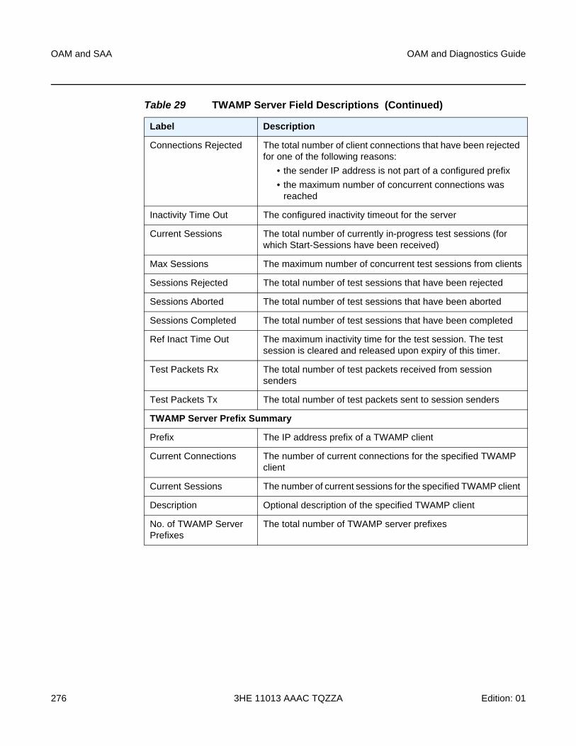
OAM and SAA
276
OAM and Diagnostics Guide
3HE 11013 AAAC TQZZA Edition: 01
Connections Rejected The total number of client connections that have been rejected for one of the following reasons:
• the sender IP address is not part of a configured prefix
• the maximum number of concurrent connections was reached
Inactivity Time Out The configured inactivity timeout for the server
Current Sessions The total number of currently in-progress test sessions (for which Start-Sessions have been received)
Max Sessions The maximum number of concurrent test sessions from clients
Sessions Rejected The total number of test sessions that have been rejected
Sessions Aborted The total number of test sessions that have been aborted
Sessions Completed The total number of test sessions that have been completed
Ref Inact Time Out The maximum inactivity time for the test session. The test session is cleared and released upon expiry of this timer.
Test Packets Rx The total number of test packets received from session senders
Test Packets Tx The total number of test packets sent to session senders
TWAMP Server Prefix Summary
Prefix The IP address prefix of a TWAMP client
Current Connections The number of current connections for the specified TWAMP client
Current Sessions The number of current sessions for the specified TWAMP client
Description Optional description of the specified TWAMP client
No. of TWAMP Server Prefixes
The total number of TWAMP server prefixes
Table 29 TWAMP Server Field Descriptions (Continued)
Label Description
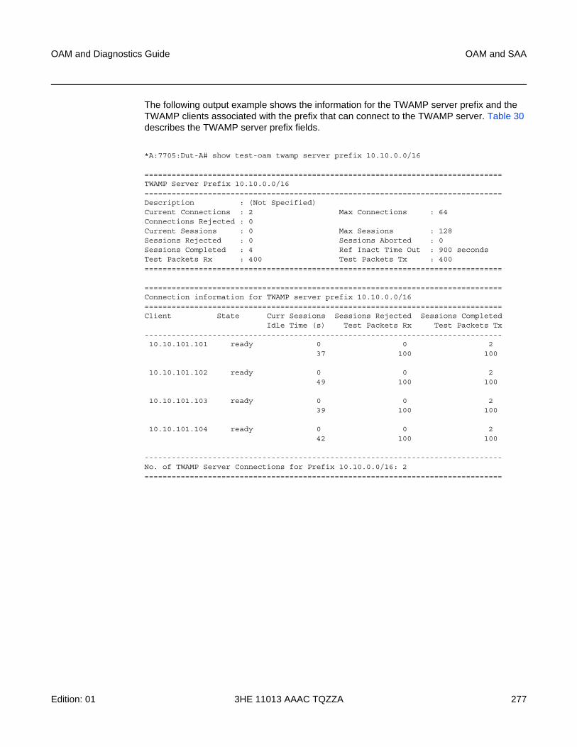
OAM and Diagnostics Guide OAM and SAA
Edition: 01 3HE 11013 AAAC TQZZA 277
The following output example shows the information for the TWAMP server prefix and the TWAMP clients associated with the prefix that can connect to the TWAMP server. Table 30 describes the TWAMP server prefix fields.
*A:7705:Dut-A# show test-oam twamp server prefix 10.10.0.0/16
===============================================================================TWAMP Server Prefix 10.10.0.0/16===============================================================================Description : (Not Specified)Current Connections : 2 Max Connections : 64Connections Rejected : 0Current Sessions : 0 Max Sessions : 128Sessions Rejected : 0 Sessions Aborted : 0Sessions Completed : 4 Ref Inact Time Out : 900 secondsTest Packets Rx : 400 Test Packets Tx : 400===============================================================================
===============================================================================Connection information for TWAMP server prefix 10.10.0.0/16===============================================================================Client State Curr Sessions Sessions Rejected Sessions Completed
Idle Time (s) Test Packets Rx Test Packets Tx-------------------------------------------------------------------------------10.10.101.101 ready 0 0 2
37 100 100
10.10.101.102 ready 0 0 249 100 100
10.10.101.103 ready 0 0 239 100 100
10.10.101.104 ready 0 0 242 100 100
-------------------------------------------------------------------------------No. of TWAMP Server Connections for Prefix 10.10.0.0/16: 2===============================================================================
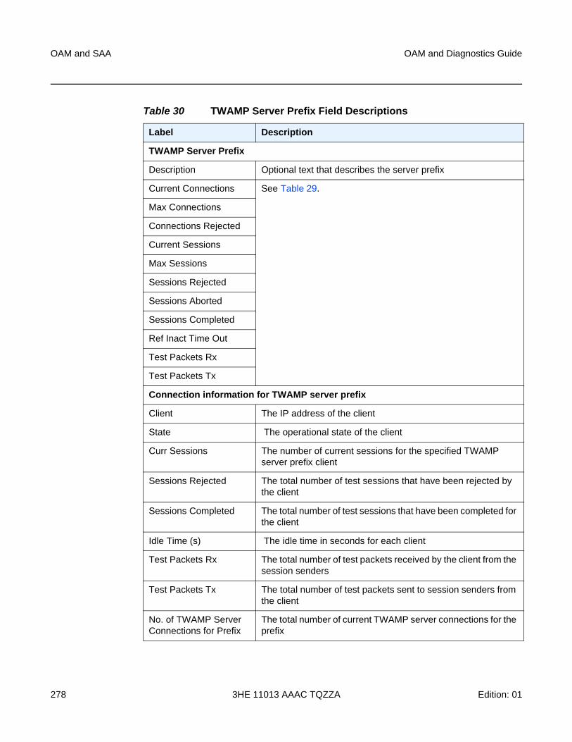
OAM and SAA
278
OAM and Diagnostics Guide
3HE 11013 AAAC TQZZA Edition: 01
Table 30 TWAMP Server Prefix Field Descriptions
Label Description
TWAMP Server Prefix
Description Optional text that describes the server prefix
Current Connections See Table 29.
Max Connections
Connections Rejected
Current Sessions
Max Sessions
Sessions Rejected
Sessions Aborted
Sessions Completed
Ref Inact Time Out
Test Packets Rx
Test Packets Tx
Connection information for TWAMP server prefix
Client The IP address of the client
State The operational state of the client
Curr Sessions The number of current sessions for the specified TWAMP server prefix client
Sessions Rejected The total number of test sessions that have been rejected by the client
Sessions Completed The total number of test sessions that have been completed for the client
Idle Time (s) The idle time in seconds for each client
Test Packets Rx The total number of test packets received by the client from the session senders
Test Packets Tx The total number of test packets sent to session senders from the client
No. of TWAMP Server Connections for Prefix
The total number of current TWAMP server connections for the prefix
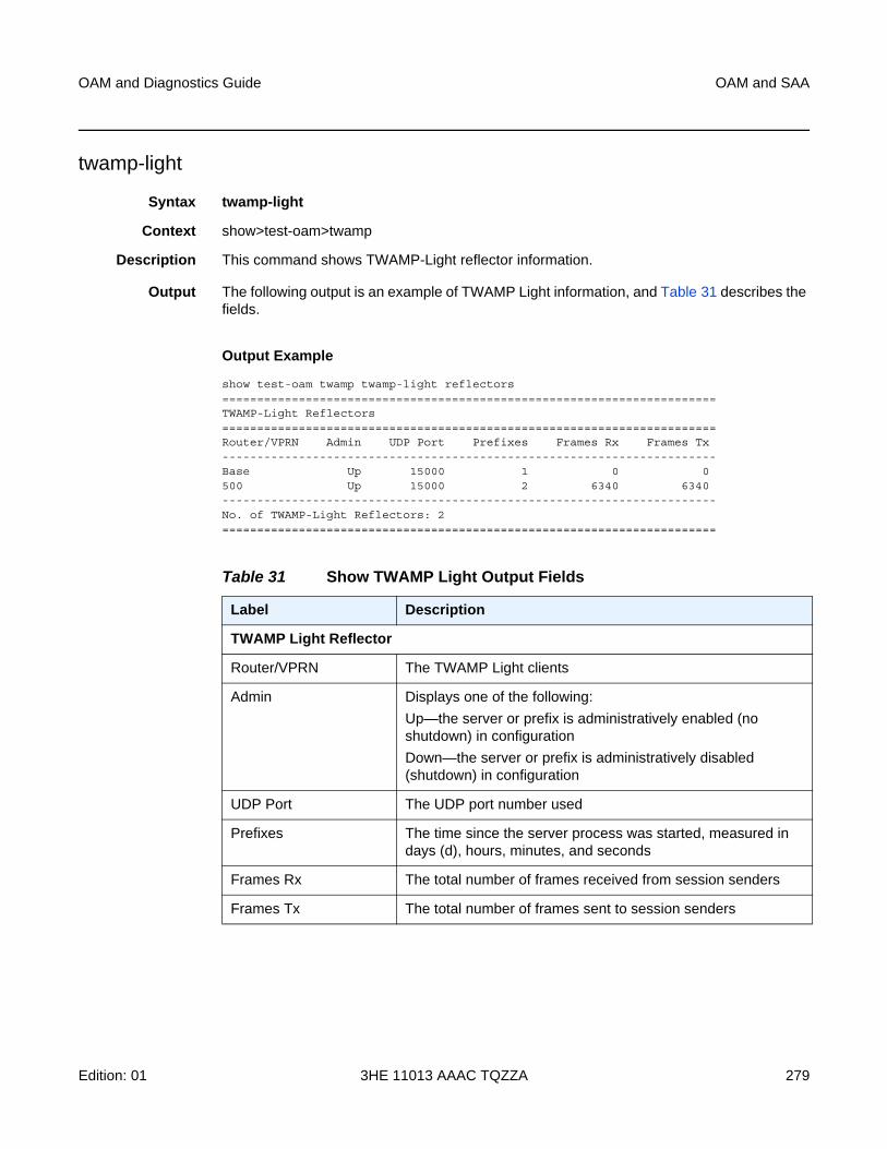
OAM and Diagnostics Guide OAM and SAA
Edition: 01 3HE 11013 AAAC TQZZA 279
twamp-light
Syntax twamp-light
Context show>test-oam>twamp
Description This command shows TWAMP-Light reflector information.
Output The following output is an example of TWAMP Light information, and Table 31 describes the fields.
Output Example
show test-oam twamp twamp-light reflectors=======================================================================TWAMP-Light Reflectors=======================================================================Router/VPRN Admin UDP Port Prefixes Frames Rx Frames Tx-----------------------------------------------------------------------Base Up 15000 1 0 0500 Up 15000 2 6340 6340-----------------------------------------------------------------------No. of TWAMP-Light Reflectors: 2=======================================================================
Table 31 Show TWAMP Light Output Fields
Label Description
TWAMP Light Reflector
Router/VPRN The TWAMP Light clients
Admin Displays one of the following:
Up—the server or prefix is administratively enabled (no shutdown) in configuration
Down—the server or prefix is administratively disabled (shutdown) in configuration
UDP Port The UDP port number used
Prefixes The time since the server process was started, measured in days (d), hours, minutes, and seconds
Frames Rx The total number of frames received from session senders
Frames Tx The total number of frames sent to session senders
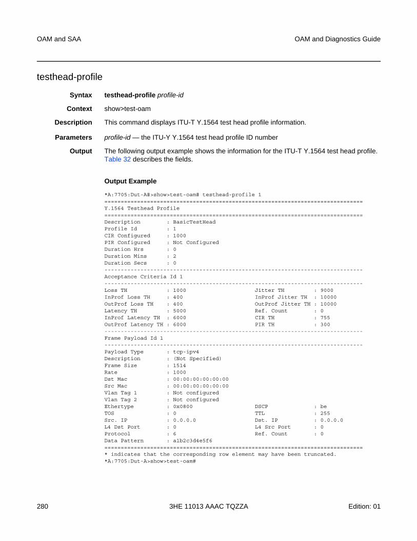
OAM and SAA
280
OAM and Diagnostics Guide
3HE 11013 AAAC TQZZA Edition: 01
testhead-profile
Syntax testhead-profile profile-id
Context show>test-oam
Description This command displays ITU-T Y.1564 test head profile information.
Parameters profile-id — the ITU-Y Y.1564 test head profile ID number
Output The following output example shows the information for the ITU-T Y.1564 test head profile. Table 32 describes the fields.
Output Example
*A:7705:Dut-A#>show>test-oam# testhead-profile 1===============================================================================Y.1564 Testhead Profile===============================================================================Description : BasicTestHeadProfile Id : 1CIR Configured : 1000PIR Configured : Not ConfiguredDuration Hrs : 0Duration Mins : 2Duration Secs : 0-------------------------------------------------------------------------------Acceptance Criteria Id 1-------------------------------------------------------------------------------Loss TH : 1000 Jitter TH : 9000InProf Loss TH : 400 InProf Jitter TH : 10000OutProf Loss TH : 400 OutProf Jitter TH : 10000Latency TH : 5000 Ref. Count : 0InProf Latency TH : 6000 CIR TH : 755OutProf Latency TH : 6000 PIR TH : 300-------------------------------------------------------------------------------Frame Payload Id 1-------------------------------------------------------------------------------Payload Type : tcp-ipv4Description : (Not Specified)Frame Size : 1514Rate : 1000Dst Mac : 00:00:00:00:00:00Src Mac : 00:00:00:00:00:00Vlan Tag 1 : Not configuredVlan Tag 2 : Not configuredEthertype : 0x0800 DSCP : beTOS : 0 TTL : 255Src. IP : 0.0.0.0 Dst. IP : 0.0.0.0L4 Dst Port : 0 L4 Src Port : 0Protocol : 6 Ref. Count : 0Data Pattern : a1b2c3d4e5f6===============================================================================* indicates that the corresponding row element may have been truncated.*A:7705:Dut-A>show>test-oam#
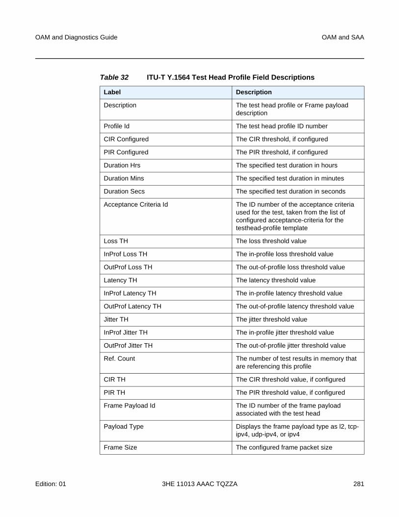
OAM and Diagnostics Guide OAM and SAA
Edition: 01 3HE 11013 AAAC TQZZA 281
Table 32 ITU-T Y.1564 Test Head Profile Field Descriptions
Label Description
Description The test head profile or Frame payload description
Profile Id The test head profile ID number
CIR Configured The CIR threshold, if configured
PIR Configured The PIR threshold, if configured
Duration Hrs The specified test duration in hours
Duration Mins The specified test duration in minutes
Duration Secs The specified test duration in seconds
Acceptance Criteria Id The ID number of the acceptance criteria used for the test, taken from the list of configured acceptance-criteria for the testhead-profile template
Loss TH The loss threshold value
InProf Loss TH The in-profile loss threshold value
OutProf Loss TH The out-of-profile loss threshold value
Latency TH The latency threshold value
InProf Latency TH The in-profile latency threshold value
OutProf Latency TH The out-of-profile latency threshold value
Jitter TH The jitter threshold value
InProf Jitter TH The in-profile jitter threshold value
OutProf Jitter TH The out-of-profile jitter threshold value
Ref. Count The number of test results in memory that are referencing this profile
CIR TH The CIR threshold value, if configured
PIR TH The PIR threshold value, if configured
Frame Payload Id The ID number of the frame payload associated with the test head
Payload Type Displays the frame payload type as l2, tcp-ipv4, udp-ipv4, or ipv4
Frame Size The configured frame packet size
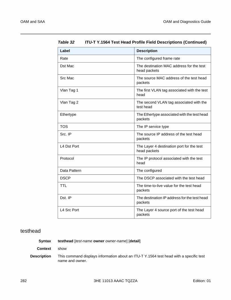
OAM and SAA
282
OAM and Diagnostics Guide
3HE 11013 AAAC TQZZA Edition: 01
testhead
Syntax testhead [test-name owner owner-name] [detail]
Context show
Description This command displays information about an ITU-T Y.1564 test head with a specific test name and owner.
Rate The configured frame rate
Dst Mac The destination MAC address for the test head packets
Src Mac The source MAC address of the test head packets
Vlan Tag 1 The first VLAN tag associated with the test head
Vlan Tag 2 The second VLAN tag associated with the test head
Ethertype The Ethertype associated with the test head packets
TOS The IP service type
Src. IP The source IP address of the test head packets
L4 Dst Port The Layer 4 destination port for the test head packets
Protocol The IP protocol associated with the test head
Data Pattern The configured
DSCP The DSCP associated with the test head
TTL The time-to-live value for the test head packets
Dst. IP The destination IP address for the test head packets
L4 Src Port The Layer 4 source port of the test head packets
Table 32 ITU-T Y.1564 Test Head Profile Field Descriptions (Continued)
Label Description
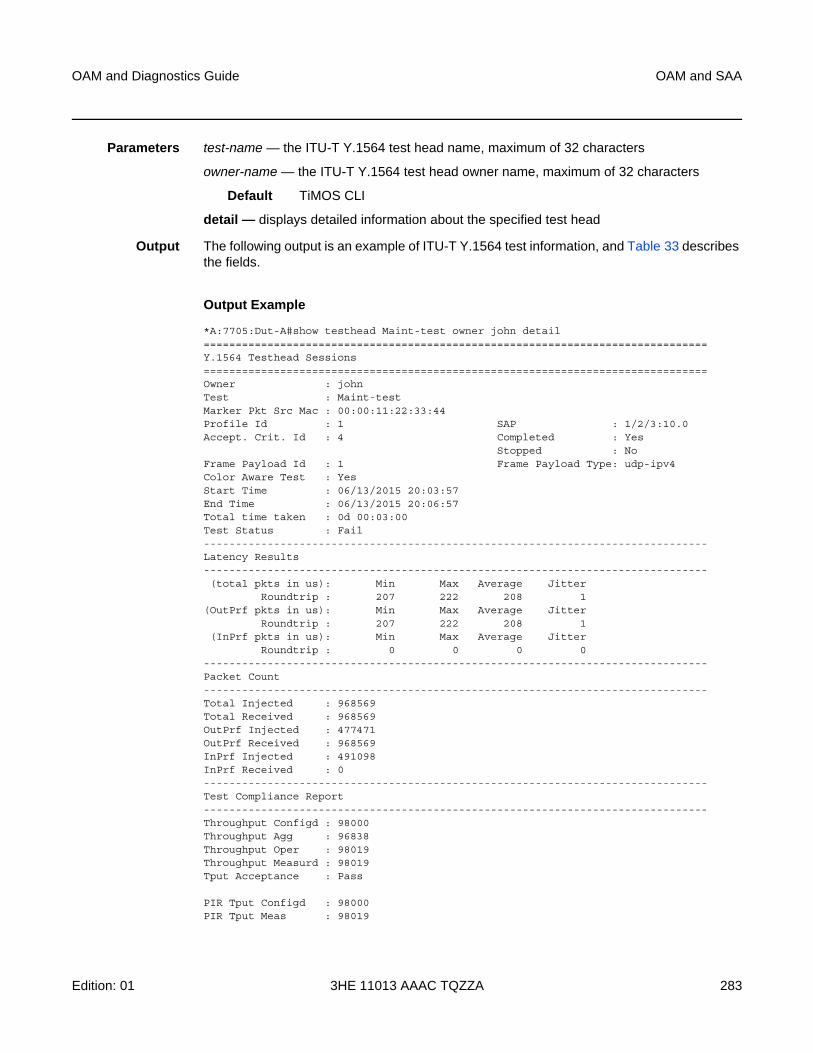
OAM and Diagnostics Guide OAM and SAA
Edition: 01 3HE 11013 AAAC TQZZA 283
Parameters test-name — the ITU-T Y.1564 test head name, maximum of 32 characters
owner-name — the ITU-T Y.1564 test head owner name, maximum of 32 characters
Default TiMOS CLI
detail — displays detailed information about the specified test head
Output The following output is an example of ITU-T Y.1564 test information, and Table 33 describes the fields.
Output Example
*A:7705:Dut-A#show testhead Maint-test owner john detail===============================================================================Y.1564 Testhead Sessions===============================================================================Owner : johnTest : Maint-testMarker Pkt Src Mac : 00:00:11:22:33:44Profile Id : 1 SAP : 1/2/3:10.0Accept. Crit. Id : 4 Completed : Yes
Stopped : NoFrame Payload Id : 1 Frame Payload Type: udp-ipv4Color Aware Test : YesStart Time : 06/13/2015 20:03:57End Time : 06/13/2015 20:06:57Total time taken : 0d 00:03:00Test Status : Fail-------------------------------------------------------------------------------Latency Results-------------------------------------------------------------------------------(total pkts in us): Min Max Average Jitter
Roundtrip : 207 222 208 1(OutPrf pkts in us): Min Max Average Jitter
Roundtrip : 207 222 208 1(InPrf pkts in us): Min Max Average Jitter
Roundtrip : 0 0 0 0-------------------------------------------------------------------------------Packet Count-------------------------------------------------------------------------------Total Injected : 968569Total Received : 968569OutPrf Injected : 477471OutPrf Received : 968569InPrf Injected : 491098InPrf Received : 0-------------------------------------------------------------------------------Test Compliance Report-------------------------------------------------------------------------------Throughput Configd : 98000Throughput Agg : 96838Throughput Oper : 98019Throughput Measurd : 98019Tput Acceptance : Pass
PIR Tput Configd : 98000PIR Tput Meas : 98019
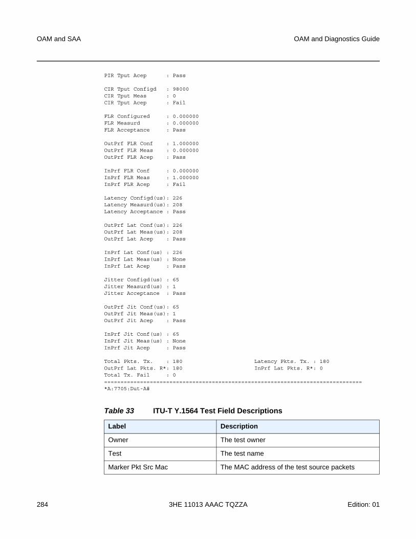
OAM and SAA
284
OAM and Diagnostics Guide
3HE 11013 AAAC TQZZA Edition: 01
PIR Tput Acep : Pass
CIR Tput Configd : 98000CIR Tput Meas : 0CIR Tput Acep : Fail
FLR Configured : 0.000000FLR Measurd : 0.000000FLR Acceptance : Pass
OutPrf FLR Conf : 1.000000OutPrf FLR Meas : 0.000000OutPrf FLR Acep : Pass
InPrf FLR Conf : 0.000000InPrf FLR Meas : 1.000000InPrf FLR Acep : Fail
Latency Configd(us): 226Latency Measurd(us): 208Latency Acceptance : Pass
OutPrf Lat Conf(us): 226OutPrf Lat Meas(us): 208OutPrf Lat Acep : Pass
InPrf Lat Conf(us) : 226InPrf Lat Meas(us) : NoneInPrf Lat Acep : Pass
Jitter Configd(us) : 65Jitter Measurd(us) : 1Jitter Acceptance : Pass
OutPrf Jit Conf(us): 65OutPrf Jit Meas(us): 1OutPrf Jit Acep : Pass
InPrf Jit Conf(us) : 65InPrf Jit Meas(us) : NoneInPrf Jit Acep : Pass
Total Pkts. Tx. : 180 Latency Pkts. Tx. : 180OutPrf Lat Pkts. R*: 180 InPrf Lat Pkts. R*: 0Total Tx. Fail : 0===============================================================================*A:7705:Dut-A#
Table 33 ITU-T Y.1564 Test Field Descriptions
Label Description
Owner The test owner
Test The test name
Marker Pkt Src Mac The MAC address of the test source packets
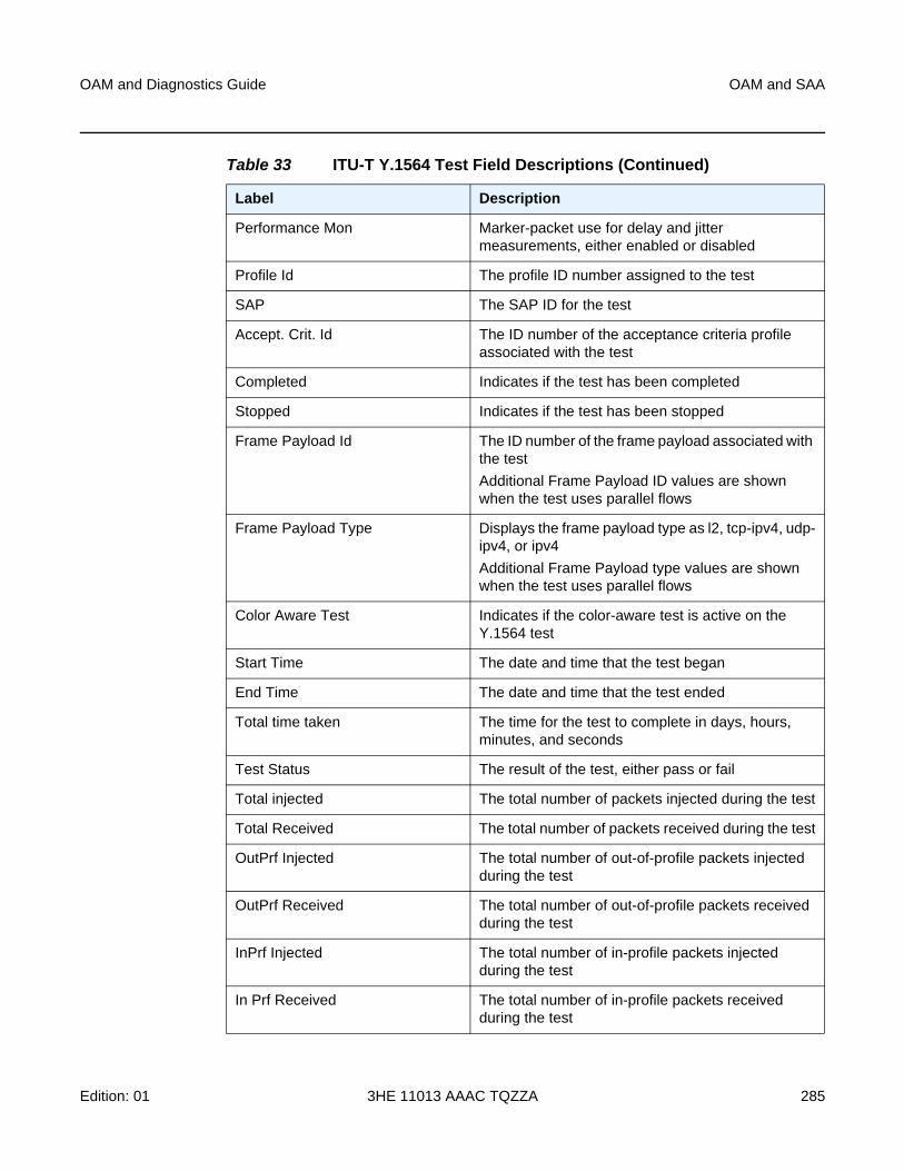
OAM and Diagnostics Guide OAM and SAA
Edition: 01 3HE 11013 AAAC TQZZA 285
Performance Mon Marker-packet use for delay and jitter measurements, either enabled or disabled
Profile Id The profile ID number assigned to the test
SAP The SAP ID for the test
Accept. Crit. Id The ID number of the acceptance criteria profile associated with the test
Completed Indicates if the test has been completed
Stopped Indicates if the test has been stopped
Frame Payload Id The ID number of the frame payload associated with the test
Additional Frame Payload ID values are shown when the test uses parallel flows
Frame Payload Type Displays the frame payload type as l2, tcp-ipv4, udp-ipv4, or ipv4
Additional Frame Payload type values are shown when the test uses parallel flows
Color Aware Test Indicates if the color-aware test is active on the Y.1564 test
Start Time The date and time that the test began
End Time The date and time that the test ended
Total time taken The time for the test to complete in days, hours, minutes, and seconds
Test Status The result of the test, either pass or fail
Total injected The total number of packets injected during the test
Total Received The total number of packets received during the test
OutPrf Injected The total number of out-of-profile packets injected during the test
OutPrf Received The total number of out-of-profile packets received during the test
InPrf Injected The total number of in-profile packets injected during the test
In Prf Received The total number of in-profile packets received during the test
Table 33 ITU-T Y.1564 Test Field Descriptions (Continued)
Label Description
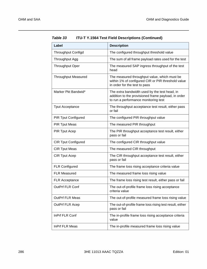
OAM and SAA
286
OAM and Diagnostics Guide
3HE 11013 AAAC TQZZA Edition: 01
Throughput Configd The configured throughput threshold value
Throughput Agg The sum of all frame payload rates used for the test
Throughput Oper The measured SAP ingress throughput of the test head
Throughput Measured The measured throughput value, which must be within 1% of configured CIR or PIR threshold value in order for the test to pass
Marker Pkt Bandwid* The extra bandwidth used by the test head, in addition to the provisioned frame payload, in order to run a performance monitoring test
Tput Acceptance The throughput acceptance test result, either pass or fail
PIR Tput Configured The configured PIR throughput value
PIR Tput Meas The measured PIR throughput
PIR Tput Acep The PIR throughput acceptance test result, either pass or fail
CIR Tput Configured The configured CIR throughput value
CIR Tput Meas The measured CIR throughput
CIR Tput Acep The CIR throughput acceptance test result, either pass or fail
FLR Configured The frame loss rising acceptance criteria value
FLR Measured The measured frame loss rising value
FLR Acceptance The frame loss rising test result, either pass or fail
OutPrf FLR Conf The out-of-profile frame loss rising acceptance criteria value
OutPrf FLR Meas The out-of-profile measured frame loss rising value
OutPrf FLR Acep The out-of-profile frame loss rising test result, either pass or fail
InPrf FLR Conf The in-profile frame loss rising acceptance criteria value
InPrf FLR Meas The in-profile measured frame loss rising value
Table 33 ITU-T Y.1564 Test Field Descriptions (Continued)
Label Description
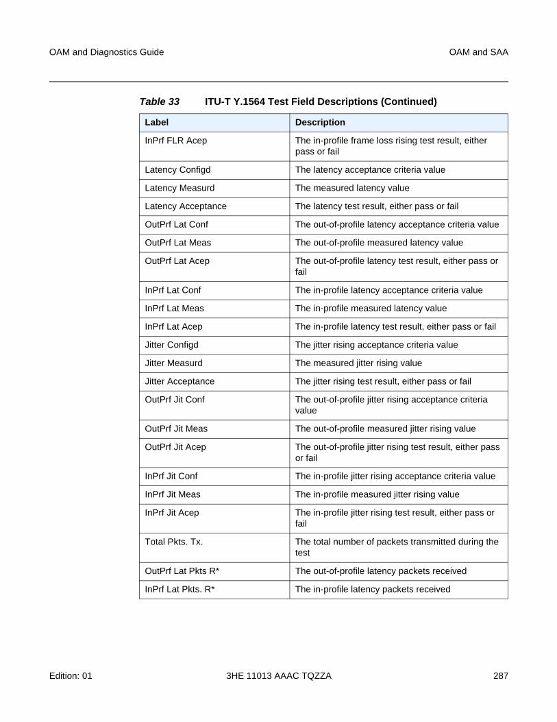
OAM and Diagnostics Guide OAM and SAA
Edition: 01 3HE 11013 AAAC TQZZA 287
InPrf FLR Acep The in-profile frame loss rising test result, either pass or fail
Latency Configd The latency acceptance criteria value
Latency Measurd The measured latency value
Latency Acceptance The latency test result, either pass or fail
OutPrf Lat Conf The out-of-profile latency acceptance criteria value
OutPrf Lat Meas The out-of-profile measured latency value
OutPrf Lat Acep The out-of-profile latency test result, either pass or fail
InPrf Lat Conf The in-profile latency acceptance criteria value
InPrf Lat Meas The in-profile measured latency value
InPrf Lat Acep The in-profile latency test result, either pass or fail
Jitter Configd The jitter rising acceptance criteria value
Jitter Measurd The measured jitter rising value
Jitter Acceptance The jitter rising test result, either pass or fail
OutPrf Jit Conf The out-of-profile jitter rising acceptance criteria value
OutPrf Jit Meas The out-of-profile measured jitter rising value
OutPrf Jit Acep The out-of-profile jitter rising test result, either pass or fail
InPrf Jit Conf The in-profile jitter rising acceptance criteria value
InPrf Jit Meas The in-profile measured jitter rising value
InPrf Jit Acep The in-profile jitter rising test result, either pass or fail
Total Pkts. Tx. The total number of packets transmitted during the test
OutPrf Lat Pkts R* The out-of-profile latency packets received
InPrf Lat Pkts. R* The in-profile latency packets received
Table 33 ITU-T Y.1564 Test Field Descriptions (Continued)
Label Description
OAM and SAA
288
OAM and Diagnostics Guide
3HE 11013 AAAC TQZZA Edition: 01
3.6.2.3 Clear Commands
saa
Syntax saa-test [test-name [owner test-owner]]
Context clear
Description This command clears the SAA results for the specified test and the history for the test. If the test name is omitted, all the results for all tests are cleared.
Parameters test-name — specifies the SAA test to clear. The test name must already be configured in the config>saa>test context.
test-owner — specifies the owner of an SAA operation, up to 32 characters in length
Default If a test-owner value is not specified, tests created by the CLI have a default owner “TiMOS CLI”
dual-ended-loss-test
Syntax dual-ended-loss-test mep mep-id domain md-index association ma-index
Context clear>eth-cfm
Description This command clears the accumulated frame counters during a dual-ended loss measurement (LM) test.
The LM counters are reset when a MEP on the datapath is created or deleted automatically by the system for network or configuration reasons. Some of the reasons for creating or deleting a MEP are as follows, excluding the general functions of manually creating or deleting a MEP:
• for SAPs
− changing the ccm-ltm-priority using the CLI or SNMP
− changing the ccm-interval using the CLI or SNMP
− changing the SAP egress QoS policy
− changes to the SAP state (due to, for example, moving (bouncing) ports, link loss forwarding (LLF), or network changes that require recreation of flows)
• for spoke SDPs
− changing the VC type on the spoke SDP
− changing the VC vc-tag on the spoke SDP
− changing the VC etype on the spoke SDP
− change to the spoke SDP state due to network conditions
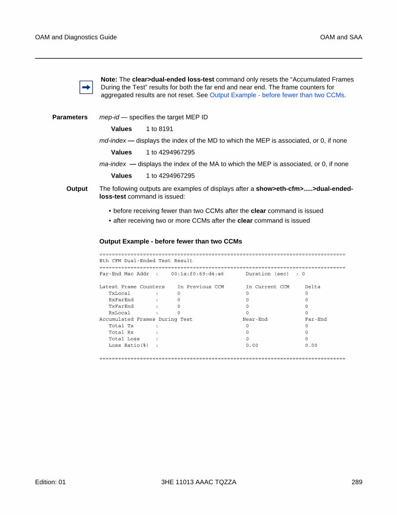
OAM and Diagnostics Guide OAM and SAA
Edition: 01 3HE 11013 AAAC TQZZA 289
Parameters mep-id — specifies the target MEP ID
Values 1 to 8191
md-index — displays the index of the MD to which the MEP is associated, or 0, if none
Values 1 to 4294967295
ma-index — displays the index of the MA to which the MEP is associated, or 0, if none
Values 1 to 4294967295
Output The following outputs are examples of displays after a show>eth-cfm>.....>dual-ended-loss-test command is issued:
• before receiving fewer than two CCMs after the clear command is issued
• after receiving two or more CCMs after the clear command is issued
Output Example - before fewer than two CCMs
===============================================================================Eth CFM Dual-Ended Test Result===============================================================================Far-End Mac Addr : 00:1a:f0:69:d4:a6 Duration (sec) : 0
Latest Frame Counters In Previous CCM In Current CCM DeltaTxLocal : 0 0 0RxFarEnd : 0 0 0TxFarEnd : 0 0 0RxLocal : 0 0 0
Accumulated Frames During Test Near-End Far-EndTotal Tx : 0 0Total Rx : 0 0Total Loss : 0 0Loss Ratio(%) : 0.00 0.00
===============================================================================
Note: The clear>dual-ended loss-test command only resets the “Accumulated Frames During the Test” results for both the far end and near end. The frame counters for aggregated results are not reset. See Output Example - before fewer than two CCMs.
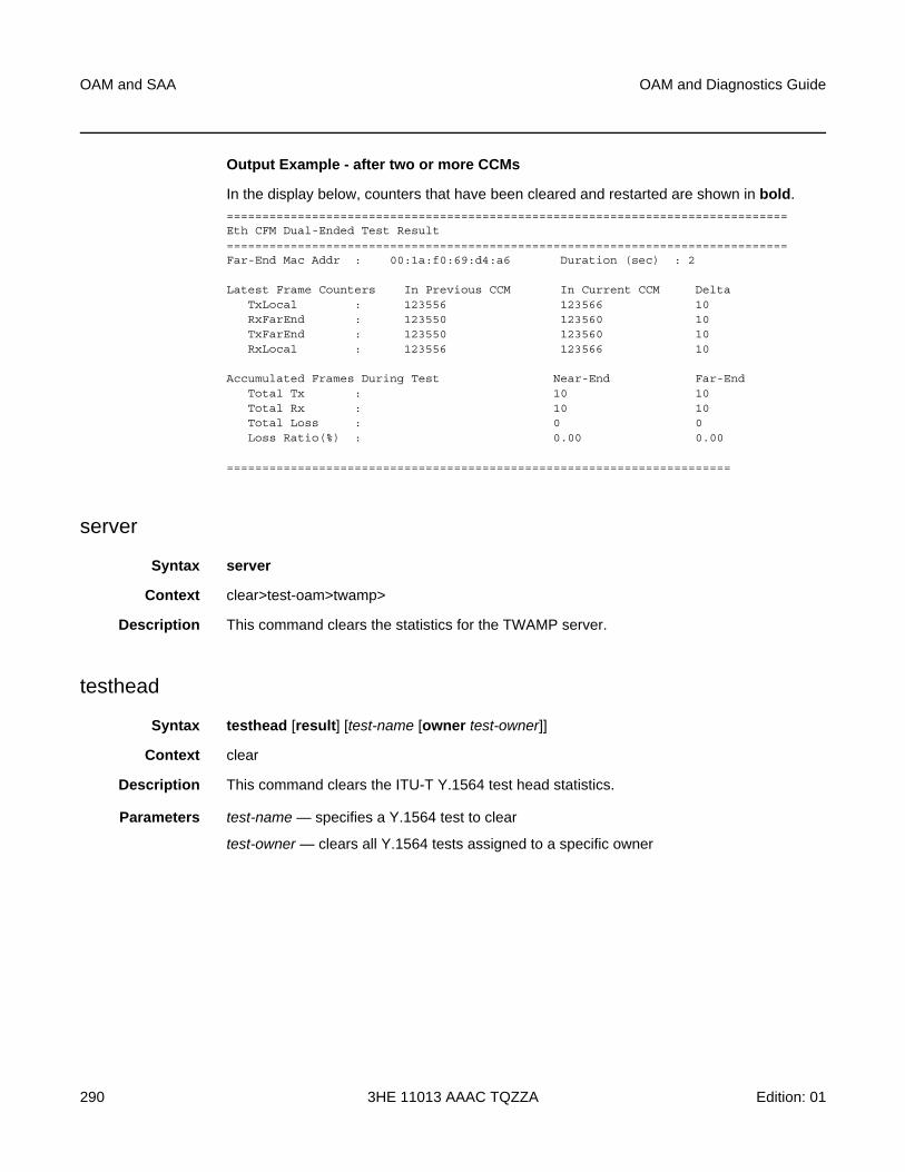
OAM and SAA
290
OAM and Diagnostics Guide
3HE 11013 AAAC TQZZA Edition: 01
Output Example - after two or more CCMs
In the display below, counters that have been cleared and restarted are shown in bold.===============================================================================Eth CFM Dual-Ended Test Result===============================================================================Far-End Mac Addr : 00:1a:f0:69:d4:a6 Duration (sec) : 2
Latest Frame Counters In Previous CCM In Current CCM DeltaTxLocal : 123556 123566 10RxFarEnd : 123550 123560 10TxFarEnd : 123550 123560 10RxLocal : 123556 123566 10
Accumulated Frames During Test Near-End Far-EndTotal Tx : 10 10Total Rx : 10 10Total Loss : 0 0Loss Ratio(%) : 0.00 0.00
=======================================================================
server
Syntax server
Context clear>test-oam>twamp>
Description This command clears the statistics for the TWAMP server.
testhead
Syntax testhead [result] [test-name [owner test-owner]]
Context clear
Description This command clears the ITU-T Y.1564 test head statistics.
Parameters test-name — specifies a Y.1564 test to clear
test-owner — clears all Y.1564 tests assigned to a specific owner

OAM and Diagnostics Guide OAM and SAA
Edition: 01 3HE 11013 AAAC TQZZA 291
3.6.2.4 Debug Commands
oam
Syntax [no] oam
Context debug
Description This command enables or disables debugging for OAM.
lsp-ping-trace
Syntax lsp-ping-trace [tx | rx | both] [raw | detail]
no lsp-ping-trace
Context debug>oam
Description This command enables debugging for LSP ping.
Parameters tx | rx | both — specifies the direction for the LSP ping debugging: transmit, receive, or both transmit and receive
raw | detail — displays output for the debug mode

OAM and SAA
292
OAM and Diagnostics Guide
3HE 11013 AAAC TQZZA Edition: 01
OAM and Diagnostics Guide Mirroring
Edition: 01 3HE 11013 AAAC TQZZA 293
4 Mirroring
This chapter provides information about mirroring support on the 7705 SAR.
Topics in this chapter include:
• Mirroring Overview
• Configuration Notes
• Configuring Mirroring with CLI
• Basic Mirroring Configuration
• Common Configuration Tasks
• Service Management Tasks
• Mirror Service Configuration Command Reference
Mirroring
294
OAM and Diagnostics Guide
3HE 11013 AAAC TQZZA Edition: 01
4.1 Mirroring Overview
To assist in troubleshooting complex operational problems, certain packets may need to be examined as they traverse the network. One way to accomplish this is with an overlay of network analyzers established at multiple PoPs, together with skilled technicians to operate them to decode the data provided. This method of traffic mirroring often requires setting up complex filters in multiple switches and/or routers. These, at best, are only able to mirror from one port to another on the same device.
Nokia support for port mirroring on the 7705 SAR extends and integrates these capabilities into the network and provides significant operational benefits. Each router can mirror packets to any Ethernet interface destination point in the network.
This capability also extends beyond troubleshooting services. Telephone companies have the ability to obtain itemized calling records and wiretaps where legally required by investigating authorities. The process can be complex and costly to carry out on data networks. Service mirroring simplifies these via mirroring of the SAP port, and reduces costs through centralization of analysis tools and skilled technicians.
Original packets are forwarded while a copy is sent out the mirrored port to the mirroring (destination) port. Mirroring allows an operator to see the actual traffic on a port with a sniffer sitting in a central location. In many cases, this reduces the need for a separate, costly overlay sniffer network.
The mirrored frame size that is to be transmitted to the mirror destination can be explicitly configured by using slicing features. This enables mirroring of only the parts needed for analysis while minimizing network resource usage. For example, only the headers can be copied for analysis, protecting the integrity and security of customer data, or conversely, copying the full packet, including customer data.
Mirroring is supported on the following hardware:
• 2-port 10GigE (Ethernet) Adapter card (only on the 2.5 Gb/s v-port)
• 6-port Ethernet 10Gbps Adapter card
• 8-port Ethernet Adapter card, version 2
• 8-port Gigabit Ethernet Adapter card version 1
• 8-port Gigabit Ethernet Adapter card version 2
• 8-port Gigabit Ethernet Adapter card version 3
• 10-port 1GigE/1-port 10GigE X-Adapter card version 1
• 10-port 1GigE/1-port 10GigE X-Adapter card version 2
• Packet Microwave Adapter card
OAM and Diagnostics Guide Mirroring
Edition: 01 3HE 11013 AAAC TQZZA 295
• 2-port 10GigE (Ethernet) module (only on the 2.5 Gb/s v-port)
• 4-port SAR-H Fast Ethernet module
• 6-port SAR-M Ethernet module
• 7705 SAR-A
• 7705 SAR-Ax
• 7705 SAR-H
• 7705 SAR-Hc
• 7705 SAR-M
• 7705 SAR-W
• 7705 SAR-Wx
• 7705 SAR-X
4.1.1 Mirroring Implementation
The 7705 SAR supports port mirroring only. The network processor of the datapath preserves the original packet throughout the forwarding and mirroring process, making any necessary packet changes, such as adding encapsulation, on a separate copy.
Nokia’s implementation of packet mirroring is based on the following assumptions.
• Ingress and egress packets are mirrored as they appear on the wire. This is important for troubleshooting encapsulation and protocol issues.
− When mirroring at ingress, the network processor sends an exact copy of the original ingress packet to the mirror destination while normal forwarding proceeds on the original packet.
− When mirroring is at egress, the system performs normal packet handling on the egress packet, encapsulating it for the destination interface. A copy of the forwarded packet is forwarded to the mirror destination. Because the mirror copy of the packet is created before egress queuing, the mirrored packet stream may include copies of packets that are discarded in egress queues, such as during congestion or rate limiting.
• Mirroring supports tunnel destinations.
− Remote destinations are reached by encapsulating the ingress or egress packet within an SDP, like the traffic for distributed VPN connectivity services. At the remote destination, the tunnel encapsulation is removed and the packet is forwarded out a local SAP.
Mirroring
296
OAM and Diagnostics Guide
3HE 11013 AAAC TQZZA Edition: 01
4.1.2 Mirror Sources and Destinations
Mirror sources and destinations have the following characteristics.
• Sources and destinations can be on the same router (local) or on two different routers (remote).
• Mirror destinations can terminate on egress virtual ports, which allows multiple mirror destinations to send to the same packet decoding device, delimited by IEEE 802.1Q (referred to as dot1q) tags. This is helpful when troubleshooting a multi-port issue within the network.
When multiple mirror destinations terminate on the same egress port, the individual dot1q tags can provide a DTE/DCE separation between the mirror sources.
• Packets ingressing a port can have a mirror destination separate from packets egressing the same port or a different port (the ports can be on separate nodes).
• Multiple mirror destinations are supported (local and/or remote) on a single node.
• The operational state of a mirror destination depends on the state of all the outputs of the mirror. The mirror destination will go operationally down if all the outputs are down (for example, all mirror-dest>sap and mirror-dest>spoke-sdp objects are down. The state of a mirror destination does not depend on inputs such as SDPs configured under mirror-dest>remote-source or debug>mirror-source entries.
4.1.2.1 Local and Remote Mirroring
Mirrored frames can be copied and sent to a specific local destination on the router (local mirroring) or copies can be encapsulated and sent to a different router (remote mirroring). This functionality allows network operators to centralize network analyzer (sniffer) resources, and also the technical staff who operate them.
The router allows multiple concurrent mirroring sessions so that traffic from more than one ingress mirror source can be mirrored to the same or different egress mirror destinations.
Remote mirroring uses an SDP, which acts as a logical way of directing traffic from one router to another through a unidirectional service tunnel. The SDP terminates at the far-end router, which directs packets to the correct destination on that device.
OAM and Diagnostics Guide Mirroring
Edition: 01 3HE 11013 AAAC TQZZA 297
The SDP configuration from the mirrored device to a far-end router requires a return path SDP from the far-end router back to the mirrored router. Each device must have an SDP defined for every remote router to which it wants to provide mirroring services. SDPs must be created first, before services can be configured.
4.1.2.2 Slicing
Another service mirroring refinement is slicing, which only mirrors a specified packet length from each frame. This is useful to monitor network usage without having to copy the actual data. Slicing enables the mirroring of larger frames than the destination packet decoding equipment can handle. It also allows conservation of mirroring resources by limiting the size of the stream of packets through the router and the core network.
When a mirror slice-size is defined, a threshold that truncates a mirrored frame to a specific size is created. For example, if the value of 256 bytes is defined, up to the first 256 bytes of the frame are transmitted to the mirror destination. The original frame is not affected by the truncation. Mirrored frames will grow larger as encapsulations are added when packets are transmitted through the network core or out the mirror destination SAP to the packet/protocol decoding equipment.
The transmission of a sliced or non-sliced frame is also dependent on the mirror destination SDP path MTU and/or the mirror destination SAP physical MTU. Packets that require a larger MTU than the mirroring destination supports are discarded if the defined slice size does not truncate the packet to an acceptable size.
4.1.3 Mirroring Performance
Replication of mirrored packets can affect performance and should be used carefully. The 7705 SAR, making use of network processor based forwarding, allows efficient mirror service scaling and, at the same time, allows a large amount of data to be mirrored with minimal performance impact. When a mirror destination is configured, the packet slice option can truncate mirrored packets to the destination, which minimizes replication and tunneling overhead.
When a packet at port ingress is mirrored, one extra buffer per packet is used. For more information, refer to the “Buffer Allocation for Multicast Traffic” section in the 7705 SAR Quality of Service Guide.
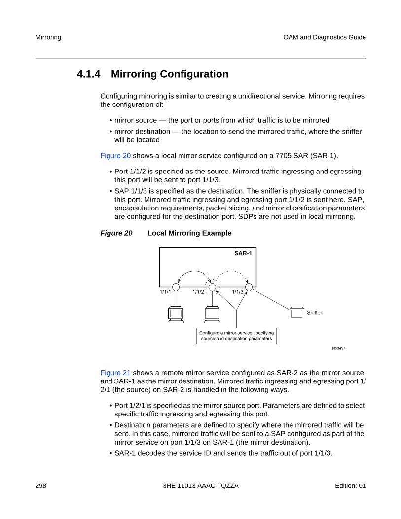
Mirroring
298
OAM and Diagnostics Guide
3HE 11013 AAAC TQZZA Edition: 01
4.1.4 Mirroring Configuration
Configuring mirroring is similar to creating a unidirectional service. Mirroring requires the configuration of:
• mirror source — the port or ports from which traffic is to be mirrored
• mirror destination — the location to send the mirrored traffic, where the sniffer will be located
Figure 20 shows a local mirror service configured on a 7705 SAR (SAR-1).
• Port 1/1/2 is specified as the source. Mirrored traffic ingressing and egressing this port will be sent to port 1/1/3.
• SAP 1/1/3 is specified as the destination. The sniffer is physically connected to this port. Mirrored traffic ingressing and egressing port 1/1/2 is sent here. SAP, encapsulation requirements, packet slicing, and mirror classification parameters are configured for the destination port. SDPs are not used in local mirroring.
Figure 20 Local Mirroring Example
Figure 21 shows a remote mirror service configured as SAR-2 as the mirror source and SAR-1 as the mirror destination. Mirrored traffic ingressing and egressing port 1/2/1 (the source) on SAR-2 is handled in the following ways.
• Port 1/2/1 is specified as the mirror source port. Parameters are defined to select specific traffic ingressing and egressing this port.
• Destination parameters are defined to specify where the mirrored traffic will be sent. In this case, mirrored traffic will be sent to a SAP configured as part of the mirror service on port 1/1/3 on SAR-1 (the mirror destination).
• SAR-1 decodes the service ID and sends the traffic out of port 1/1/3.
No3497
1/1/1 1/1/2 1/1/3
Sniffer
Configure a mirror service specifyingsource and destination parameters
SAR-1
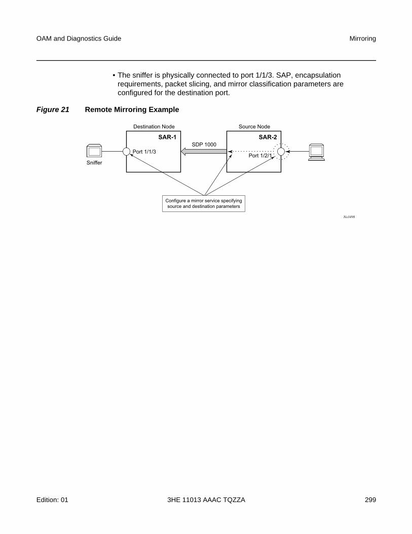
OAM and Diagnostics Guide Mirroring
Edition: 01 3HE 11013 AAAC TQZZA 299
• The sniffer is physically connected to port 1/1/3. SAP, encapsulation requirements, packet slicing, and mirror classification parameters are configured for the destination port.
Figure 21 Remote Mirroring Example
No3498
Sniffer
Port 1/1/3Port 1/2/1
SDP 1000
Destination Node
Configure a mirror service specifyingsource and destination parameters
SAR-1
Source Node
SAR-2
Mirroring
300
OAM and Diagnostics Guide
3HE 11013 AAAC TQZZA Edition: 01
4.2 Configuration Notes
This section describes mirroring configuration guidelines and caveats.
• Multiple mirroring service IDs (mirror destinations) may be created within a single system.
• A mirrored source can only have one destination.
• The destination mirroring service IDs and service parameters are persistent between router reboots and are included in the configuration saves.
Mirror source criteria configuration (defined in debug>mirror-source) is not preserved in a configuration save (admin save). Debug mirror source configuration can be saved using admin>debug-save.
• Physical layer problems such as collisions and jabbers are not mirrored. Typically, only complete packets are mirrored.
• When starting or shutting down mirroring on mirror destinations, the following must be considered.
− The default state for a mirror destination service ID is shutdown. You must issue a no shutdown command to enable the feature.
− When a mirror destination service ID is shut down, mirrored packets associated with the service ID are not accepted from its mirror source or remote source. The associated mirror source is put into an operationally down mode. Mirrored packets are not transmitted out the SAP or SDP. Each mirrored packet is silently discarded. If the mirror destination is a SAP, the SAP’s discard counters are incremented.
− Issuing the shutdown command causes the mirror destination service or its mirror source to be put into an administratively down state. Mirror destination service IDs must be shut down first in order to delete a service ID, SAP, or SDP association from the system.
When starting or shutting down mirroring on mirror sources, the following must be considered.
− The default state for a mirror source for a given mirror destination service ID is no shutdown. You must enter a shutdown command to deactivate (disable) mirroring from that mirror source.
− Mirror sources do not need to be shut down to remove them from the system. When a mirror source is shut down, mirroring is terminated for all sources defined locally for the mirror destination service ID.
OAM and Diagnostics Guide Mirroring
Edition: 01 3HE 11013 AAAC TQZZA 301
4.3 Configuring Mirroring with CLI
This section provides information about configuring service mirroring using CLI.
Topics in this section include:
• Basic Mirroring Configuration
• Common Configuration Tasks
• Service Management Tasks
4.3.1 Mirror Configuration Overview
Mirroring can be organized into the following logical entities.
• The mirror source is the location where ingress or egress traffic specific to a port is to be mirrored (copied). The original frames are not altered or affected in any way.
• An SDP is used to define the mirror destination on the source router to point to a remote destination (another router).
• A SAP is defined in local and remote mirror services as the mirror destination to which the mirrored packets are sent.

Mirroring
302
OAM and Diagnostics Guide
3HE 11013 AAAC TQZZA Edition: 01
4.4 Basic Mirroring Configuration
Mirror destination parameters must include:
• a mirror destination ID (same as the mirror source service ID)
• a mirror destination SAP or SDP
Mirror source parameters must include:
• a mirror service ID (same as the mirror destination service ID)
• the source type (port)
The following example shows a configuration of a local mirrored service where the source and destinations are on the same device.
*A:SAR-1>config>mirror# info----------------------------------------------
mirror-dest 103 createsap 1/1/25:0 create
egressqos 1
exitexitno shutdown
exit----------------------------------------------*A:SAR-1>config>mirror#
The following example shows a mirror source configuration:
*A:SAR-1>show debug mirrordebug
mirror-source 103port 1/1/24 egress ingress
no shutdownexit
exit*A:SAR-1>debug>mirror-source# exit
The following example shows a configuration of a remote mirrored service where the source is a port on SAR-1 and the destination is a SAP on SAR-2:
*A:SAR-1>config>mirror# info----------------------------------------------
mirror-dest 1000 createspoke-sdp 2:1 egr-vc-label 7000no shutdown
exit----------------------------------------------*A:SAR-1>config>mirror# exit all*A:SAR-1# show debug
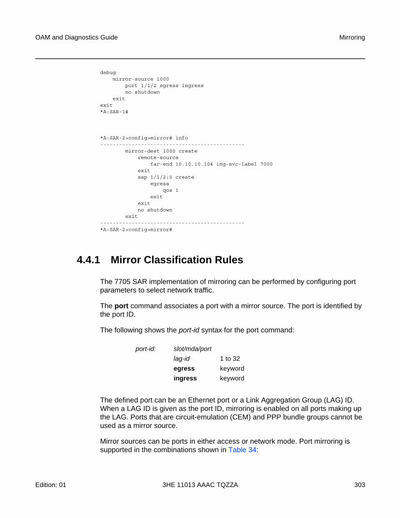
OAM and Diagnostics Guide Mirroring
Edition: 01 3HE 11013 AAAC TQZZA 303
debugmirror-source 1000
port 1/1/2 egress ingressno shutdown
exitexit*A:SAR-1#
*A:SAR-2>config>mirror# info----------------------------------------------
mirror-dest 1000 createremote-source
far-end 10.10.10.104 ing-svc-label 7000exitsap 1/1/2:0 create
egressqos 1
exitexitno shutdown
exit----------------------------------------------*A:SAR-2>config>mirror#
4.4.1 Mirror Classification Rules
The 7705 SAR implementation of mirroring can be performed by configuring port parameters to select network traffic.
The port command associates a port with a mirror source. The port is identified by the port ID.
The following shows the port-id syntax for the port command:
The defined port can be an Ethernet port or a Link Aggregation Group (LAG) ID. When a LAG ID is given as the port ID, mirroring is enabled on all ports making up the LAG. Ports that are circuit-emulation (CEM) and PPP bundle groups cannot be used as a mirror source.
Mirror sources can be ports in either access or network mode. Port mirroring is supported in the combinations shown in Table 34:
port-id: slot/mda/port
lag-id 1 to 32
egress keyword
ingress keyword
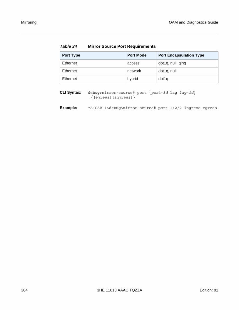
Mirroring
304
OAM and Diagnostics Guide
3HE 11013 AAAC TQZZA Edition: 01
CLI Syntax: debug>mirror-source# port {port-id|lag lag-id} {[egress][ingress]}
Example: *A:SAR-1>debug>mirror-source# port 1/2/2 ingress egress
Table 34 Mirror Source Port Requirements
Port Type Port Mode Port Encapsulation Type
Ethernet access dot1q, null, qinq
Ethernet network dot1q, null
Ethernet hybrid dot1q
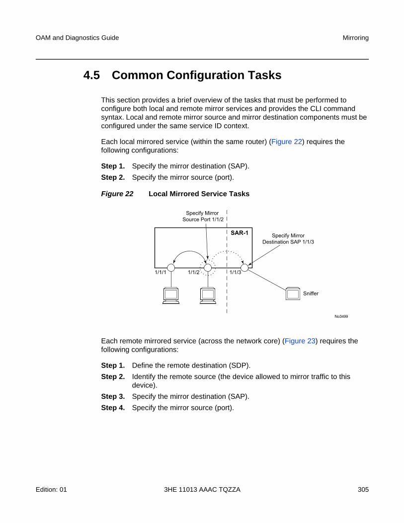
OAM and Diagnostics Guide Mirroring
Edition: 01 3HE 11013 AAAC TQZZA 305
4.5 Common Configuration Tasks
This section provides a brief overview of the tasks that must be performed to configure both local and remote mirror services and provides the CLI command syntax. Local and remote mirror source and mirror destination components must be configured under the same service ID context.
Each local mirrored service (within the same router) (Figure 22) requires the following configurations:
Step 1. Specify the mirror destination (SAP).
Step 2. Specify the mirror source (port).
Figure 22 Local Mirrored Service Tasks
Each remote mirrored service (across the network core) (Figure 23) requires the following configurations:
Step 1. Define the remote destination (SDP).
Step 2. Identify the remote source (the device allowed to mirror traffic to this device).
Step 3. Specify the mirror destination (SAP).
Step 4. Specify the mirror source (port).
No3499
1/1/1 1/1/2 1/1/3
Specify MirrorDestination SAP 1/1/3
Specify Mirror Source Port 1/1/2
Sniffer
SAR-1
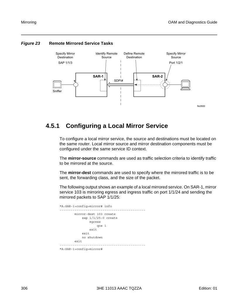
Mirroring
306
OAM and Diagnostics Guide
3HE 11013 AAAC TQZZA Edition: 01
Figure 23 Remote Mirrored Service Tasks
4.5.1 Configuring a Local Mirror Service
To configure a local mirror service, the source and destinations must be located on the same router. Local mirror source and mirror destination components must be configured under the same service ID context.
The mirror-source commands are used as traffic selection criteria to identify traffic to be mirrored at the source.
The mirror-dest commands are used to specify where the mirrored traffic is to be sent, the forwarding class, and the size of the packet.
The following output shows an example of a local mirrored service. On SAR-1, mirror service 103 is mirroring egress and ingress traffic on port 1/1/24 and sending the mirrored packets to SAP 1/1/25:
*A:SAR-1>config>mirror# info----------------------------------------------
mirror-dest 103 createsap 1/1/25:0 create
egressqos 1
exitexitno shutdown
exit----------------------------------------------*A:SAR-1>config>mirror#
No3500
Sniffer
SDP #SAR-1 SAR-2
Define RemoteDestination
Identify RemoteSource
Specify MirrorSource
Port 1/2/1
Specify MirrorDestination
SAP 1/1/3
OAM and Diagnostics Guide Mirroring
Edition: 01 3HE 11013 AAAC TQZZA 307
The following output shows debug mirroring information:
*A:SAR-1>show debug mirror----------------------------------------------
debugmirror-source 103
no shutdownport 1/1/24 egress ingress
exitexit
----------------------------------------------*A:SAR-1>debug>mirror-source# exit
4.5.2 Configuring SDPs for Mirroring
This section provides a brief overview of the tasks that must be performed to configure SDPs and provides the CLI commands. For more information about service configuration, refer to the 7705 SAR Services Guide.
The following SDP characteristics apply:
• The SDP must be configured for GRE or MPLS encapsulation.
• Each distributed service must have an SDP defined for every remote 7705 SAR to provide Epipe, VPLS, or mirrored services.
• A distributed service must be bound to an SDP. By default, no SDP is associated with a service. Once an SDP is created, services can be associated with that SDP.
• An SDP is not specific to any one service or any type of service. An SDP can have more than one service bound to it.
• For SDPs use remote-source>far-end entries. Remote source far-end details are configured in the destination node.
• To configure an MPLS SDP, LSPs must be configured first and then the LSP-to-SDP association must be explicitly created.
To configure a basic SDP, perform the following steps:
Step 1. Select an originating node.
Step 2. Create an SDP ID.
Step 3. Select an encapsulation type.
Step 4. Select the far-end node.
To configure the return path SDP, perform the same steps on the far-end router.
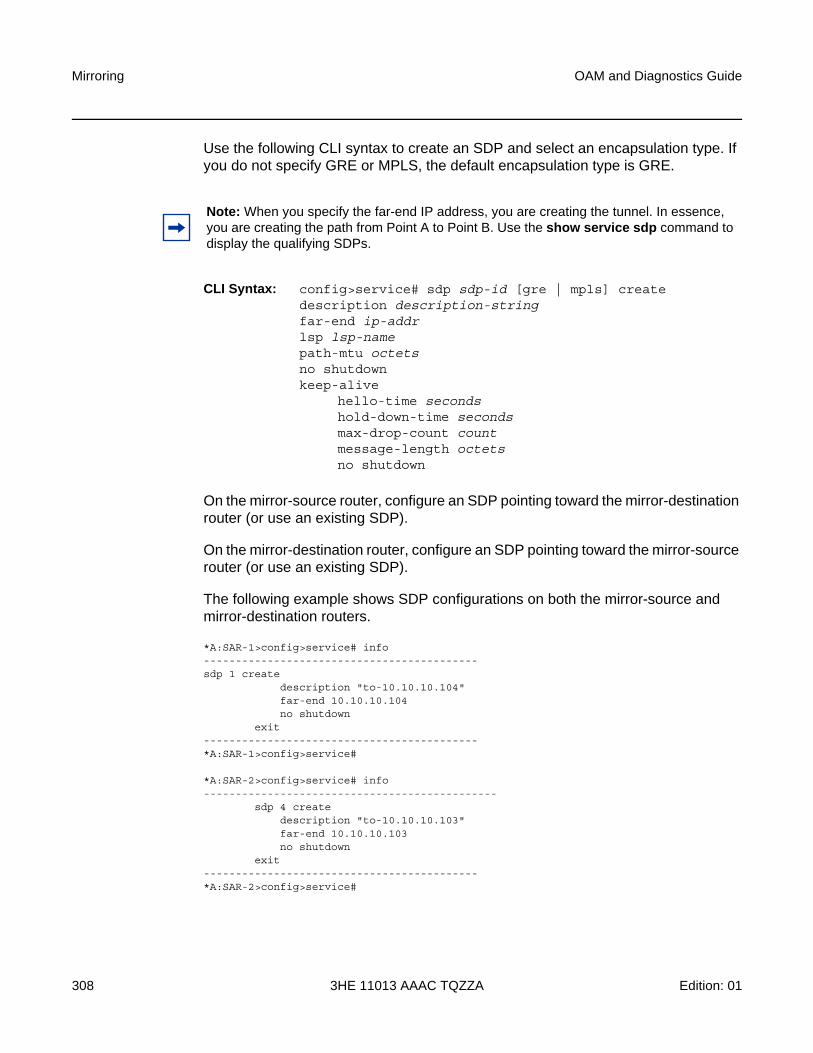
Mirroring
308
OAM and Diagnostics Guide
3HE 11013 AAAC TQZZA Edition: 01
Use the following CLI syntax to create an SDP and select an encapsulation type. If you do not specify GRE or MPLS, the default encapsulation type is GRE.
CLI Syntax: config>service# sdp sdp-id [gre | mpls] createdescription description-stringfar-end ip-addrlsp lsp-namepath-mtu octetsno shutdown keep-alive
hello-time secondshold-down-time secondsmax-drop-count countmessage-length octetsno shutdown
On the mirror-source router, configure an SDP pointing toward the mirror-destination router (or use an existing SDP).
On the mirror-destination router, configure an SDP pointing toward the mirror-source router (or use an existing SDP).
The following example shows SDP configurations on both the mirror-source and mirror-destination routers.
*A:SAR-1>config>service# info-------------------------------------------sdp 1 create
description "to-10.10.10.104"far-end 10.10.10.104no shutdown
exit-------------------------------------------*A:SAR-1>config>service#
*A:SAR-2>config>service# info----------------------------------------------
sdp 4 createdescription "to-10.10.10.103"far-end 10.10.10.103no shutdown
exit-------------------------------------------*A:SAR-2>config>service#
Note: When you specify the far-end IP address, you are creating the tunnel. In essence, you are creating the path from Point A to Point B. Use the show service sdp command to display the qualifying SDPs.
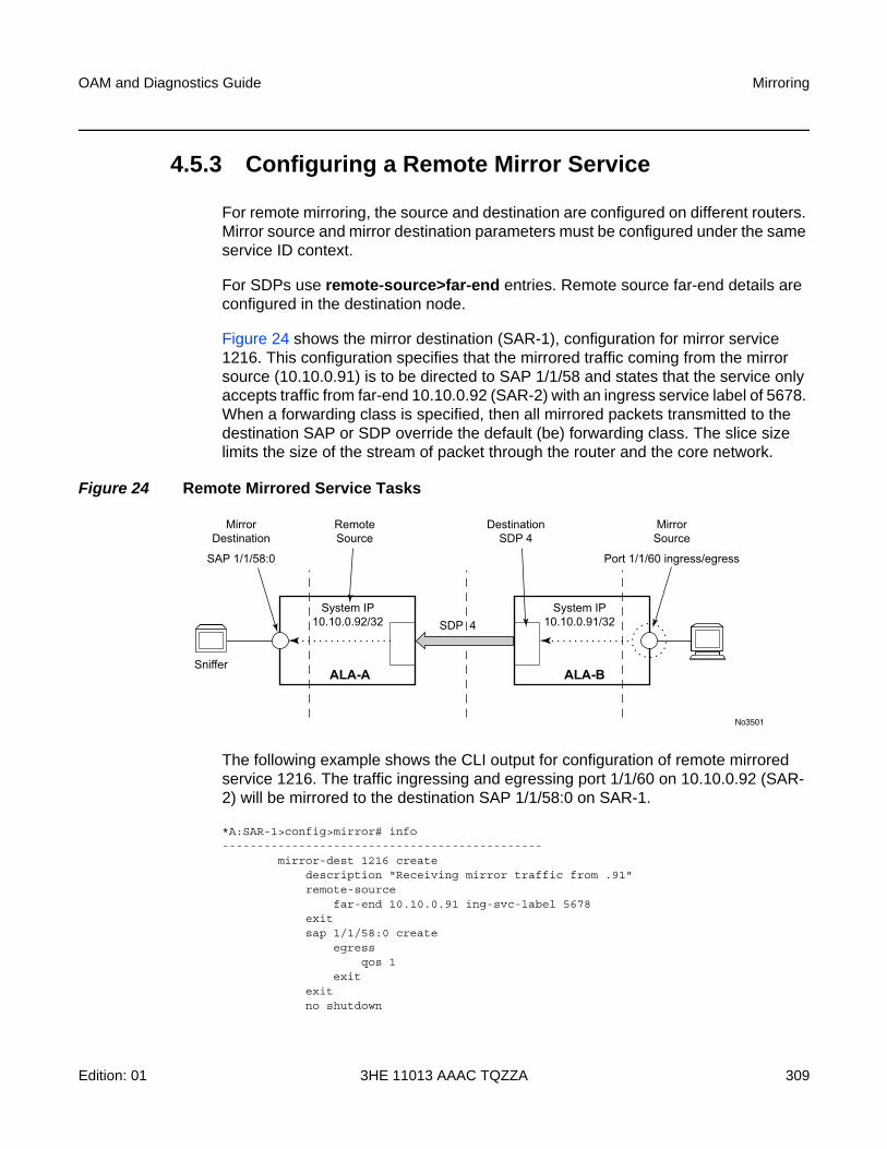
OAM and Diagnostics Guide Mirroring
Edition: 01 3HE 11013 AAAC TQZZA 309
4.5.3 Configuring a Remote Mirror Service
For remote mirroring, the source and destination are configured on different routers. Mirror source and mirror destination parameters must be configured under the same service ID context.
For SDPs use remote-source>far-end entries. Remote source far-end details are configured in the destination node.
Figure 24 shows the mirror destination (SAR-1), configuration for mirror service 1216. This configuration specifies that the mirrored traffic coming from the mirror source (10.10.0.91) is to be directed to SAP 1/1/58 and states that the service only accepts traffic from far-end 10.10.0.92 (SAR-2) with an ingress service label of 5678. When a forwarding class is specified, then all mirrored packets transmitted to the destination SAP or SDP override the default (be) forwarding class. The slice size limits the size of the stream of packet through the router and the core network.
Figure 24 Remote Mirrored Service Tasks
The following example shows the CLI output for configuration of remote mirrored service 1216. The traffic ingressing and egressing port 1/1/60 on 10.10.0.92 (SAR-2) will be mirrored to the destination SAP 1/1/58:0 on SAR-1.
*A:SAR-1>config>mirror# info----------------------------------------------
mirror-dest 1216 createdescription "Receiving mirror traffic from .91"remote-source
far-end 10.10.0.91 ing-svc-label 5678exitsap 1/1/58:0 create
egressqos 1
exitexitno shutdown
No3501
Sniffer
SDP 4System IP
10.10.0.92/32System IP
10.10.0.91/32
ALA-A ALA-B
DestinationSDP 4
RemoteSource
MirrorSource
Port 1/1/60 ingress/egress
MirrorDestination
SAP 1/1/58:0
Mirroring
310
OAM and Diagnostics Guide
3HE 11013 AAAC TQZZA Edition: 01
exit----------------------------------------------*A:SAR-1>config>mirror#
The following example shows the remote mirror destination configured on SAR-2:
*A:SAR-2>config>mirror># info----------------------------------------------mirror-dest 1216 createdescription "Sending mirrored traffic to .92"fc h1spoke-sdp 4:60 createegressvc-label 5678exitno shutdownexitslice-size 128no shutdownexit----------------------------------------------*A:SAR-2>config>mirror#
The following example shows the mirror source configuration for SAR-2:
*A:SAR-2# show debug mirror----------------------------------------------
debugmirror-source 1216
port 1/1/60 egress ingressno shutdown
exitexit
----------------------------------------------*A:SAR-2#
The following example shows the SDP configuration from SAR-1 to SAR-2 (SDP 2) and the SDP configuration from SAR-2 to SAR-1 (SDP 4):
*A:SAR-1>config>service>sdp# info---------------------------------------------
description "GRE-10.10.0.91"far-end 10.10.0.91no shutdown
---------------------------------------------*A:SAR-1>config>service>sdp#
*A:SAR-2>config>service>sdp# info----------------------------------------------
description "GRE-10.10.20.92"far-end 10.10.0.92no shutdown
----------------------------------------------*A:SAR-2>config>service>sdp#
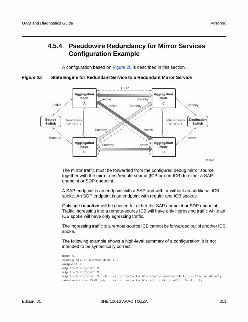
OAM and Diagnostics Guide Mirroring
Edition: 01 3HE 11013 AAAC TQZZA 311
4.5.4 Pseudowire Redundancy for Mirror Services Configuration Example
A configuration based on Figure 25 is described in this section.
Figure 25 State Engine for Redundant Service to a Redundant Mirror Service
The mirror traffic must be forwarded from the configured debug mirror source together with the mirror dest/remote source (ICB or non-ICB) to either a SAP endpoint or SDP endpoint.
A SAP endpoint is an endpoint with a SAP and with or without an additional ICB spoke. An SDP endpoint is an endpoint with regular and ICB spokes.
Only one tx-active will be chosen for either the SAP endpoint or SDP endpoint. Traffic ingressing into a remote-source ICB will have only ingressing traffic while an ICB spoke will have only egressing traffic.
The ingressing traffic to a remote-source ICB cannot be forwarded out of another ICB spoke.
The following example shows a high-level summary of a configuration; it is not intended to be syntactically correct:
Node A:config mirror mirror-dest 100endpoint Xsdp to-C endpoint Xsdp to-D endpoint Xsdp to-B endpoint X icb // connects to B’s remote-source IP-A, traffic A->B onlyremote-source IP-B icb // connects to B’s sdp to-A, traffic B->A only
No3502
AggregationNodeA
AggregationNodeC
DestinationSwitch
SourceSwitch
AggregationNodeB
AggregationNodeD
Inter-chassisPW for VLL
Active
Active
Active
Active
Standby
Standby
Standby
Standby
Standby
TLDP
Standby Active
Active
Inter-chassisPW for VLL
Mirroring
312
OAM and Diagnostics Guide
3HE 11013 AAAC TQZZA Edition: 01
Node B:config mirror mirror-dest 100endpoint Xsdp to-C endpoint Xsdp to-D endpoint Xsdp to-A endpoint X icb // connects to A’s remote-source IP-B, traffic B->A onlyremote-source IP-A icb // connects to Node A’s sdp to-B, traffic A->B only
Node C:config mirror mirror-dest 100endpoint Xsap to-destination-switch endpoint Xsdp to-D endpoint X icb // connects to D’s remote-source IP-C, traffic C->D onlyremote-source IP-Aremote-source IP-Bremote-source IP-D icb // connects to D’s sdp to-C, traffic D->C only
Node D:config mirror mirror-dest 100endpoint Xsap to-destination-switch endpoint Xsdp to-C endpoint X icb // connects to C’s remote-source IP-D, traffic D->C onlyremote-source IP-Aremote-source IP-Bremote-source IP-C icb // connects to C’s sdp to-D, traffic C->D only
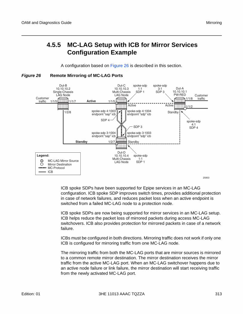
OAM and Diagnostics Guide Mirroring
Edition: 01 3HE 11013 AAAC TQZZA 313
4.5.5 MC-LAG Setup with ICB for Mirror Services Configuration Example
A configuration based on Figure 26 is described in this section.
Figure 26 Remote Mirroring of MC-LAG Ports
ICB spoke SDPs have been supported for Epipe services in an MC-LAG configuration. ICB spoke SDP improves switch times, provides additional protection in case of network failures, and reduces packet loss when an active endpoint is switched from a failed MC-LAG node to a protection node.
ICB spoke SDPs are now being supported for mirror services in an MC-LAG setup. ICB helps reduce the packet loss of mirrored packets during access MC-LAG switchovers. ICB also provides protection for mirrored packets in case of a network failure.
ICBs must be configured in both directions. Mirroring traffic does not work if only one ICB is configured for mirroring traffic from one MC-LAG node.
The mirroring traffic from both the MC-LAG ports that are mirror sources is mirrored to a common remote mirror destination. The mirror destination receives the mirror traffic from the active MC-LAG port. When an MC-LAG switchover happens due to an active node failure or link failure, the mirror destination will start receiving traffic from the newly activated MC-LAG port.
Dut-B10.10.10.2
Single-ChassisLAG Node
Dut-C10.10.10.3
Multi-ChassisLAG Node
Dut-D10.10.10.4
Multi-ChassisLAG Node
Dut-A10.10.10.1PW-RED
Customertraffic 1/1/5 1/1/5
1/2/7
spoke-sdp1:1
SDP 1
spoke-sdp3:1
SDP 3
spoke-sdp4:1
SDP 4
1/1/7
1/2/8
Customertraffic1/1/8
1/1/2
Active
Standby
Active
Standby
Active
Standby
spoke-sdp1:1
SDP 1
spoke-sdp 4:1003endpoint “sap” icb
spoke-sdp 4:1004endpoint “sdp” icb
spoke-sdp 3:1004endpoint “sap” icb
spoke-sdp 3:1003endpoint “sdp” icb
SDP 4
SDP 3
Mirror DestinationMC-LAG Mirror Source
MC-Protocol
Legend:
ICB
25953
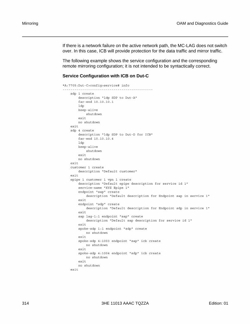
Mirroring
314
OAM and Diagnostics Guide
3HE 11013 AAAC TQZZA Edition: 01
If there is a network failure on the active network path, the MC-LAG does not switch over. In this case, ICB will provide protection for the data traffic and mirror traffic.
The following example shows the service configuration and the corresponding remote mirroring configuration; it is not intended to be syntactically correct.
Service Configuration with ICB on Dut-C
*A:7705:Dut-C>config>service# info----------------------------------------------
sdp 1 createdescription "ldp SDP to Dut-A"far-end 10.10.10.1ldpkeep-alive
shutdownexitno shutdown
exitsdp 4 create
description "ldp SDP to Dut-D for ICB"far-end 10.10.10.4ldpkeep-alive
shutdownexitno shutdown
exitcustomer 1 create
description "Default customer"exitepipe 1 customer 1 vpn 1 create
description "Default epipe description for service id 1"service-name "XYZ Epipe 1"endpoint "sap" create
description "Default description for Endpoint sap in service 1"exitendpoint "sdp" create
description "Default description for Endpoint sdp in service 1"exitsap lag-1:1 endpoint "sap" create
description "Default sap description for service id 1"exitspoke-sdp 1:1 endpoint "sdp" create
no shutdownexitspoke-sdp 4:1003 endpoint "sap" icb create
no shutdownexitspoke-sdp 4:1004 endpoint "sdp" icb create
no shutdownexitno shutdown
exit
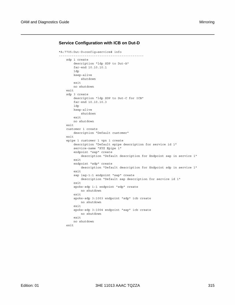
OAM and Diagnostics Guide Mirroring
Edition: 01 3HE 11013 AAAC TQZZA 315
Service Configuration with ICB on Dut-D
*A:7705:Dut-D>config>service# info----------------------------------------------
sdp 1 createdescription "ldp SDP to Dut-A"far-end 10.10.10.1ldpkeep-alive
shutdownexitno shutdown
exitsdp 3 create
description "ldp SDP to Dut-C for ICB"far-end 10.10.10.3ldpkeep-alive
shutdownexitno shutdown
exitcustomer 1 create
description "Default customer"exitepipe 1 customer 1 vpn 1 create
description "Default epipe description for service id 1"service-name "XYZ Epipe 1"endpoint "sap" create
description "Default description for Endpoint sap in service 1"exitendpoint "sdp" create
description "Default description for Endpoint sdp in service 1"exitsap lag-1:1 endpoint "sap" create
description "Default sap description for service id 1"exitspoke-sdp 1:1 endpoint "sdp" create
no shutdownexitspoke-sdp 3:1003 endpoint "sdp" icb create
no shutdownexitspoke-sdp 3:1004 endpoint "sap" icb create
no shutdownexitno shutdown
exit
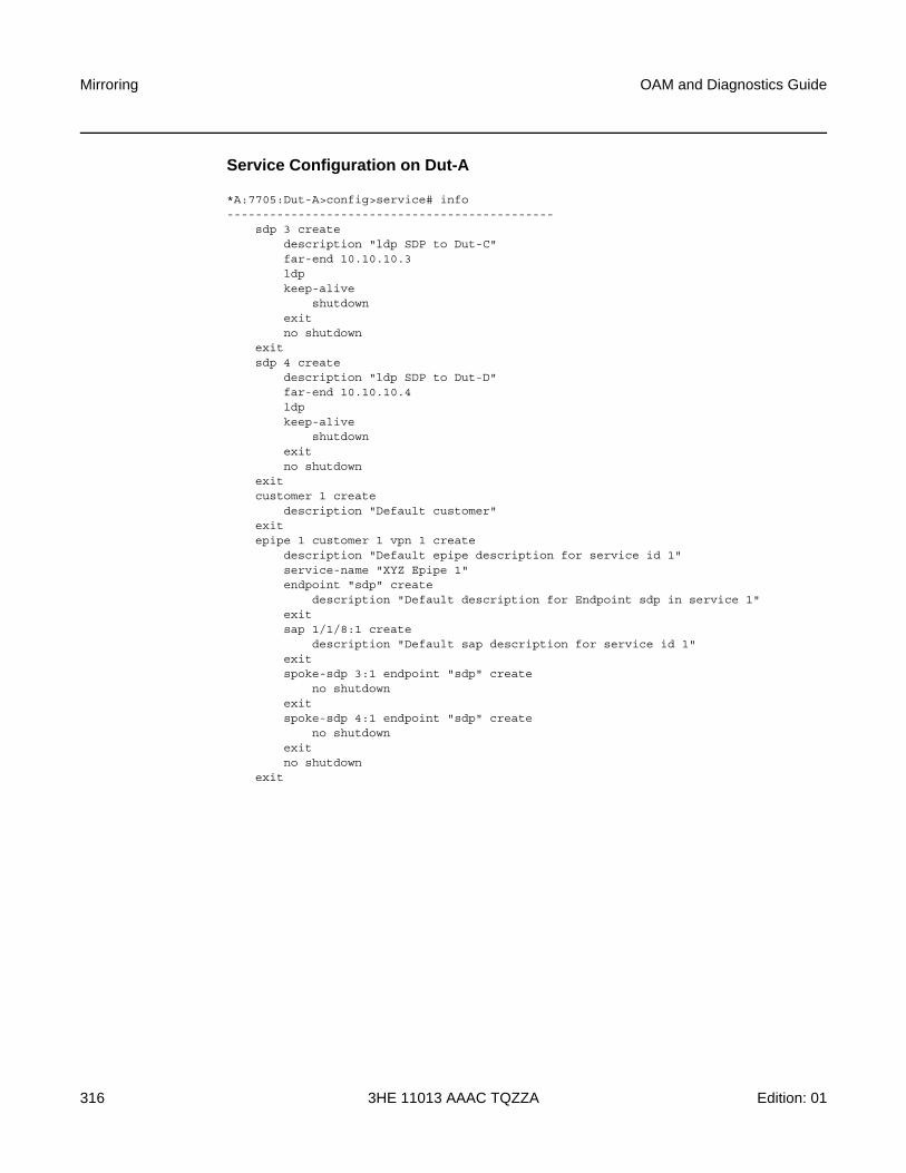
Mirroring
316
OAM and Diagnostics Guide
3HE 11013 AAAC TQZZA Edition: 01
Service Configuration on Dut-A
*A:7705:Dut-A>config>service# info----------------------------------------------
sdp 3 createdescription "ldp SDP to Dut-C"far-end 10.10.10.3ldpkeep-alive
shutdownexitno shutdown
exitsdp 4 create
description "ldp SDP to Dut-D"far-end 10.10.10.4ldpkeep-alive
shutdownexitno shutdown
exitcustomer 1 create
description "Default customer"exitepipe 1 customer 1 vpn 1 create
description "Default epipe description for service id 1"service-name "XYZ Epipe 1"endpoint "sdp" create
description "Default description for Endpoint sdp in service 1"exitsap 1/1/8:1 create
description "Default sap description for service id 1"exitspoke-sdp 3:1 endpoint "sdp" create
no shutdownexitspoke-sdp 4:1 endpoint "sdp" create
no shutdownexitno shutdown
exit

OAM and Diagnostics Guide Mirroring
Edition: 01 3HE 11013 AAAC TQZZA 317
Mirror Configuration for Dut-C (MC-LAG Port as Mirror Source)
*A:7705:Dut-C>config>mirror# info----------------------------------------------
mirror-dest 9000 createendpoint "sdp" createexitremote-source
far-end 10.10.10.4 ing-svc-label 9004 icbexitspoke-sdp 1:9001 endpoint "sdp" create
egressvc-label 9001
exitno shutdown
exitspoke-sdp 4:9003 endpoint "sdp" icb create
egressvc-label 9003
exitno shutdown
exitno shutdown
exit----------------------------------------------
*A:7705:Dut-C>show debugdebug
mirror-source 9000port lag-1 egress ingressno shutdown
exitexit
Mirror Configuration for Dut-D (MC-LAG Port as Mirror Source)
*A:7705:Dut-D>config>mirror# info----------------------------------------------
mirror-dest 9000 createendpoint "sdp" createexitremote-source
far-end 10.10.10.3 ing-svc-label 9003 icbexitspoke-sdp 1:9002 endpoint "sdp" create
egressvc-label 9002
exitno shutdown
exitspoke-sdp 3:9004 endpoint "sdp" icb create
egressvc-label 9004
exitno shutdown
exitno shutdown
exit
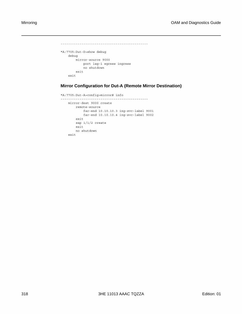
Mirroring
318
OAM and Diagnostics Guide
3HE 11013 AAAC TQZZA Edition: 01
----------------------------------------------
*A:7705:Dut-D>show debugdebug
mirror-source 9000port lag-1 egress ingressno shutdown
exitexit
Mirror Configuration for Dut-A (Remote Mirror Destination)
*A:7705:Dut-A>config>mirror# info----------------------------------------------
mirror-dest 9000 createremote-source
far-end 10.10.10.3 ing-svc-label 9001far-end 10.10.10.4 ing-svc-label 9002
exitsap 1/1/2 createexitno shutdown
exit
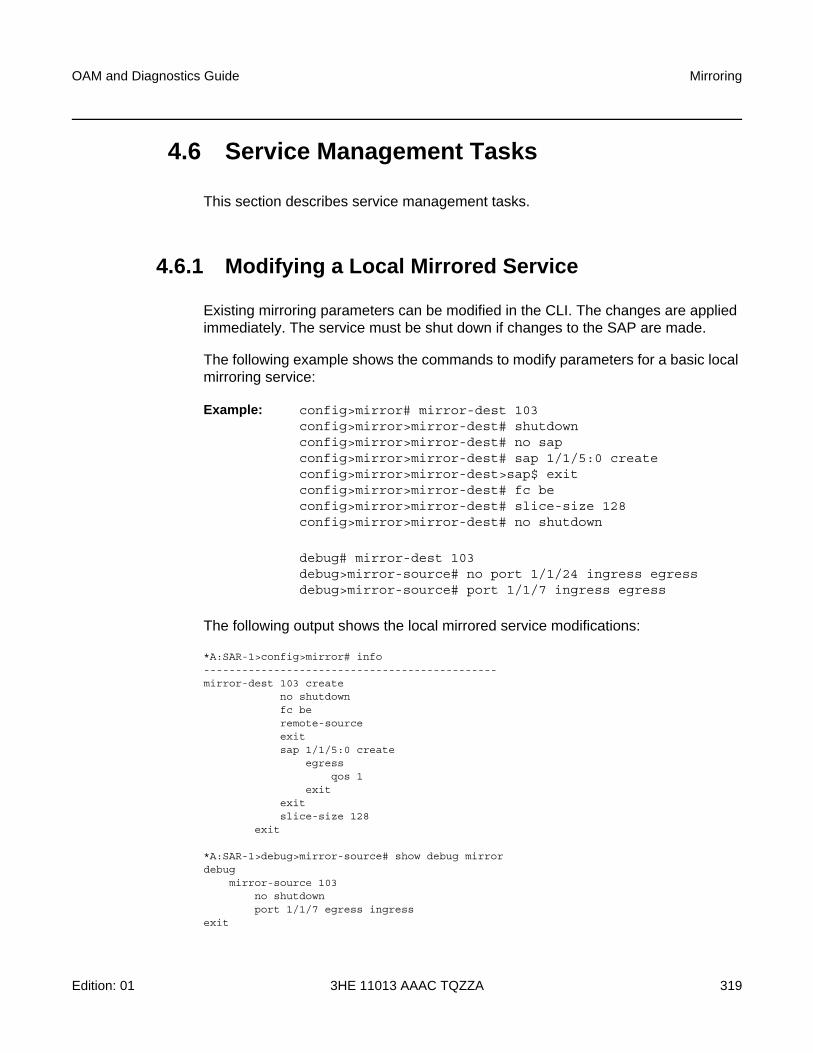
OAM and Diagnostics Guide Mirroring
Edition: 01 3HE 11013 AAAC TQZZA 319
4.6 Service Management Tasks
This section describes service management tasks.
4.6.1 Modifying a Local Mirrored Service
Existing mirroring parameters can be modified in the CLI. The changes are applied immediately. The service must be shut down if changes to the SAP are made.
The following example shows the commands to modify parameters for a basic local mirroring service:
Example: config>mirror# mirror-dest 103config>mirror>mirror-dest# shutdownconfig>mirror>mirror-dest# no sapconfig>mirror>mirror-dest# sap 1/1/5:0 createconfig>mirror>mirror-dest>sap$ exitconfig>mirror>mirror-dest# fc beconfig>mirror>mirror-dest# slice-size 128config>mirror>mirror-dest# no shutdown
debug# mirror-dest 103debug>mirror-source# no port 1/1/24 ingress egressdebug>mirror-source# port 1/1/7 ingress egress
The following output shows the local mirrored service modifications:
*A:SAR-1>config>mirror# info----------------------------------------------mirror-dest 103 create
no shutdownfc beremote-sourceexitsap 1/1/5:0 create
egressqos 1
exitexitslice-size 128
exit
*A:SAR-1>debug>mirror-source# show debug mirrordebug
mirror-source 103no shutdownport 1/1/7 egress ingress
exit
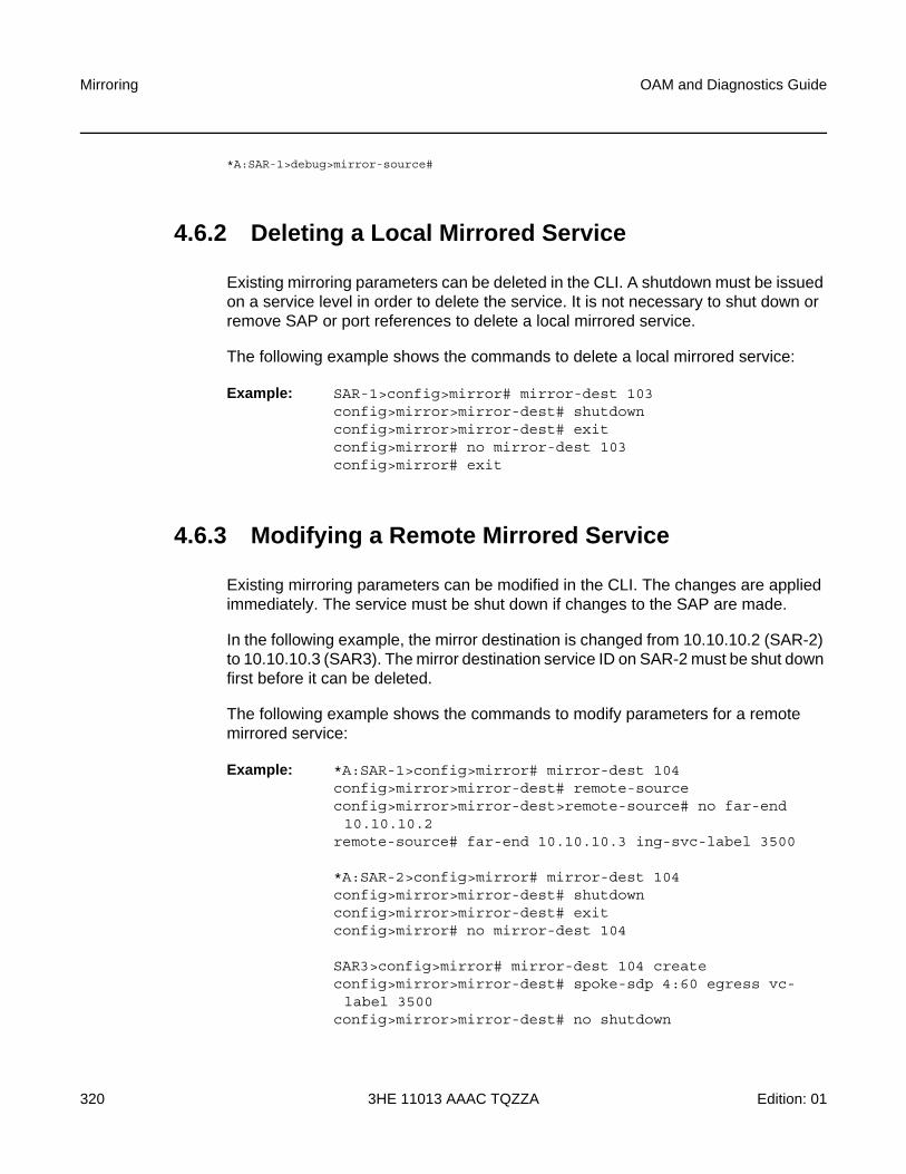
Mirroring
320
OAM and Diagnostics Guide
3HE 11013 AAAC TQZZA Edition: 01
*A:SAR-1>debug>mirror-source#
4.6.2 Deleting a Local Mirrored Service
Existing mirroring parameters can be deleted in the CLI. A shutdown must be issued on a service level in order to delete the service. It is not necessary to shut down or remove SAP or port references to delete a local mirrored service.
The following example shows the commands to delete a local mirrored service:
Example: SAR-1>config>mirror# mirror-dest 103config>mirror>mirror-dest# shutdownconfig>mirror>mirror-dest# exitconfig>mirror# no mirror-dest 103config>mirror# exit
4.6.3 Modifying a Remote Mirrored Service
Existing mirroring parameters can be modified in the CLI. The changes are applied immediately. The service must be shut down if changes to the SAP are made.
In the following example, the mirror destination is changed from 10.10.10.2 (SAR-2) to 10.10.10.3 (SAR3). The mirror destination service ID on SAR-2 must be shut down first before it can be deleted.
The following example shows the commands to modify parameters for a remote mirrored service:
Example: *A:SAR-1>config>mirror# mirror-dest 104config>mirror>mirror-dest# remote-sourceconfig>mirror>mirror-dest>remote-source# no far-end 10.10.10.2
remote-source# far-end 10.10.10.3 ing-svc-label 3500
*A:SAR-2>config>mirror# mirror-dest 104config>mirror>mirror-dest# shutdownconfig>mirror>mirror-dest# exitconfig>mirror# no mirror-dest 104
SAR3>config>mirror# mirror-dest 104 createconfig>mirror>mirror-dest# spoke-sdp 4:60 egress vc-label 3500
config>mirror>mirror-dest# no shutdown
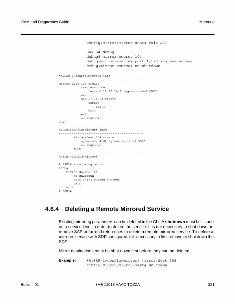
OAM and Diagnostics Guide Mirroring
Edition: 01 3HE 11013 AAAC TQZZA 321
config>mirror>mirror-dest# exit all
SAR3># debugdebug# mirror-source 104debug>mirror-source# port 1/1/2 ingress egressdebug>mirror-source# no shutdown
*A:SAR-1>config>mirror# info----------------------------------------------mirror-dest 104 create
remote-sourcefar-end 10.10.10.3 ing-svc-label 3500
exitsap 1/1/15:0 create
egressqos 1
exitexitno shutdown
exit
A:SAR3>config>mirror# info----------------------------------------------
mirror-dest 104 createspoke-sdp 4:60 egress vc-label 3500no shutdown
exit----------------------------------------------A:SAR3>config>mirror#
A:SAR3# show debug mirrordebug
mirror-source 104no shutdownport 1/1/2 egress ingressexit
exitA:SAR3#
4.6.4 Deleting a Remote Mirrored Service
Existing mirroring parameters can be deleted in the CLI. A shutdown must be issued on a service level in order to delete the service. It is not necessary to shut down or remove SAP or far-end references to delete a remote mirrored service. To delete a mirrored service with SDP configured, it is necessary to first remove or shut down the SDP.
Mirror destinations must be shut down first before they can be deleted.
Example: *A:SAR-1>config>mirror# mirror-dest 105config>mirror>mirror-dest# shutdown
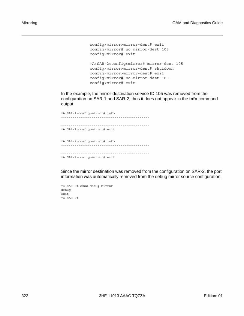
Mirroring
322
OAM and Diagnostics Guide
3HE 11013 AAAC TQZZA Edition: 01
config>mirror>mirror-dest# exitconfig>mirror# no mirror-dest 105config>mirror# exit
*A:SAR-2>config>mirror# mirror-dest 105config>mirror>mirror-dest# shutdownconfig>mirror>mirror-dest# exitconfig>mirror# no mirror-dest 105config>mirror# exit
In the example, the mirror-destination service ID 105 was removed from the configuration on SAR-1 and SAR-2, thus it does not appear in the info command output.
*A:SAR-1>config>mirror# info----------------------------------------------
----------------------------------------------*A:SAR-1>config>mirror# exit
*A:SAR-2>config>mirror# info----------------------------------------------
----------------------------------------------*A:SAR-2>config>mirror# exit
Since the mirror destination was removed from the configuration on SAR-2, the port information was automatically removed from the debug mirror source configuration.
*A:SAR-2# show debug mirrordebugexit*A:SAR-2#
OAM and Diagnostics Guide Mirroring
Edition: 01 3HE 11013 AAAC TQZZA 323
4.7 Mirror Service Configuration Command Reference
4.7.1 Command Hierarchies
• Mirror Configuration Commands
• Show Commands
• Debug Commands
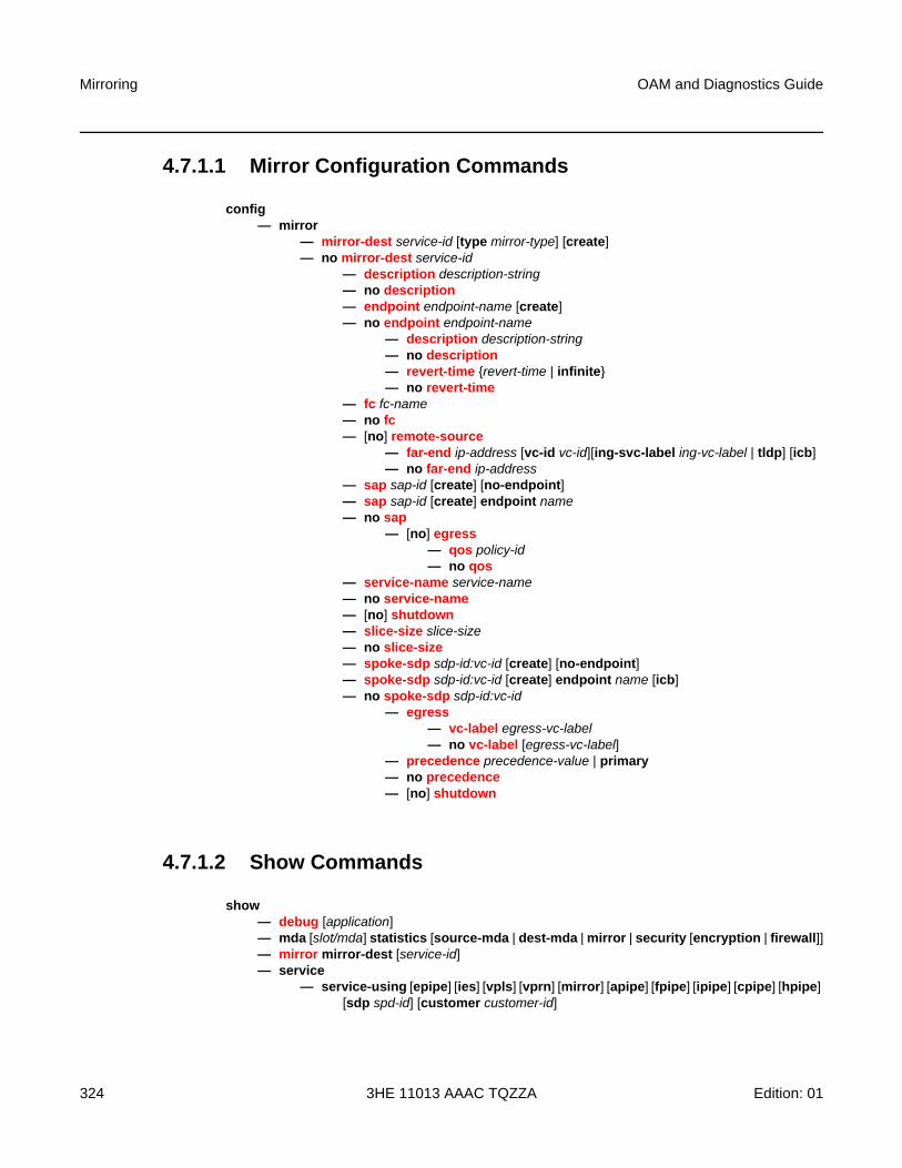
Mirroring
324
OAM and Diagnostics Guide
3HE 11013 AAAC TQZZA Edition: 01
4.7.1.1 Mirror Configuration Commands
config— mirror
— mirror-dest service-id [type mirror-type] [create]— no mirror-dest service-id
— description description-string— no description— endpoint endpoint-name [create]— no endpoint endpoint-name
— description description-string— no description— revert-time {revert-time | infinite}— no revert-time
— fc fc-name— no fc— [no] remote-source
— far-end ip-address [vc-id vc-id][ing-svc-label ing-vc-label | tldp] [icb]— no far-end ip-address
— sap sap-id [create] [no-endpoint]— sap sap-id [create] endpoint name— no sap
— [no] egress— qos policy-id— no qos
— service-name service-name— no service-name— [no] shutdown— slice-size slice-size— no slice-size— spoke-sdp sdp-id:vc-id [create] [no-endpoint]— spoke-sdp sdp-id:vc-id [create] endpoint name [icb] — no spoke-sdp sdp-id:vc-id
— egress— vc-label egress-vc-label— no vc-label [egress-vc-label]
— precedence precedence-value | primary— no precedence— [no] shutdown
4.7.1.2 Show Commands
show— debug [application]— mda [slot/mda] statistics [source-mda | dest-mda | mirror | security [encryption | firewall]]— mirror mirror-dest [service-id]— service
— service-using [epipe] [ies] [vpls] [vprn] [mirror] [apipe] [fpipe] [ipipe] [cpipe] [hpipe] [sdp spd-id] [customer customer-id]
OAM and Diagnostics Guide Mirroring
Edition: 01 3HE 11013 AAAC TQZZA 325
4.7.1.3 Debug Commands
debug— [no] mirror-source service-id
— port {port-id | lag lag-id} {[egress] [ingress]}— no port {port-id | lag lag-id} [egress] [ingress]— [no] shutdown
Mirroring
326
OAM and Diagnostics Guide
3HE 11013 AAAC TQZZA Edition: 01
4.7.2 Command Descriptions
• Configuration Commands
• Show Commands
• Debug Commands
OAM and Diagnostics Guide Mirroring
Edition: 01 3HE 11013 AAAC TQZZA 327
4.7.2.1 Configuration Commands
• Generic Commands
• Mirror Destination Configuration Commands
Mirroring
328
OAM and Diagnostics Guide
3HE 11013 AAAC TQZZA Edition: 01
4.7.2.1.1 Generic Commands
description
Syntax description description-string
no description
Context config>mirror>mirror-destconfig>mirror>mirror-dest>endpoint
Description This command creates a text description stored in the configuration file for a configuration context to help the administrator identify the content of the file.
The no form of the command removes the description string from the configuration.
Default no description
Parameters description-string — the description character string. Allowed values are any string up to 80 characters long composed of printable, 7-bit ASCII characters. If the string contains special characters (#, $, spaces, etc.), the entire string must be enclosed within double quotes.
shutdown
Syntax [no] shutdown
Context config>mirror>mirror-destconfig>mirror>mirror-dest>spoke-sdpdebug>mirror-source
Description The shutdown command administratively disables an entity. The operational state of the entity is disabled as well as the operational state of any entities contained within. When disabled, an entity does not change, reset, or remove any configuration settings or statistics. Many objects must be shut down before they may be deleted. Many entities must be explicitly enabled using the no shutdown command.
Unlike other commands and parameters where the default state is not indicated in the configuration file, shutdown and no shutdown are always indicated in system-generated configuration files.
The no form of the command puts an entity into the administratively enabled state.
Default shutdown (for mirror destination service ID)
no shutdown (for source destination service ID)

OAM and Diagnostics Guide Mirroring
Edition: 01 3HE 11013 AAAC TQZZA 329
Special Cases Mirror destination — When a mirror destination service ID is shut down, mirrored packets associated with the service ID are not accepted from the mirror source or remote source router. The associated mirror source is put into an operationally down mode. Mirrored packets are not transmitted out of the SAP or SDP. Each mirrored packet is silently discarded. If the mirror destination is a SAP, the SAP’s discard counters are incremented.
The shutdown command places the mirror destination service or mirror source into an administratively down state. The mirror-dest service ID must be shut down in order to delete the service ID, SAP or SDP association from the system.
The default state for a mirror destination service ID is shutdown. A no shutdown command is required to enable the service.
Mirror source — Mirror sources do not need to be shut down in order to remove them from the system.
When a mirror source is shutdown, mirroring is terminated for all sources defined locally for the mirror-dest service ID. If the remote-source command has been executed on the mirror-dest associated with the shutdown mirror-source, mirroring continues for remote sources.
The default state for a mirror source for a given mirror-dest service ID is no shutdown. A shutdown command is required to disable mirroring from that mirror source.
Mirroring
330
OAM and Diagnostics Guide
3HE 11013 AAAC TQZZA Edition: 01
4.7.2.1.2 Mirror Destination Configuration Commands
mirror-dest
Syntax mirror-dest service-id [type mirror-type] [create]
no mirror-dest service-id
Context config>mirror
Description This command creates a context to set up a service that is intended for packet mirroring. It is configured as a service to allow mirrored packets to be directed locally (within the same router) or remotely over the core of the network with a far-end decoding mirror encapsulation.
The mirror-dest service is composed of destination parameters that define where the mirrored packets are to be sent. It also specifies whether the defined service-id will receive mirrored packets from a far-end router over the network core.
The mirror-dest service IDs are persistent between boots of the router and are included in the configuration saves. The local sources of mirrored packets for the service ID are defined within the debug mirror-source command that references the same service-id. Up to 255 mirror-dest service IDs can be created within a single system.
When a mirror destination is configured on the 7705 SAR, the debug mirror-source service-id is automatically created and the following lines are automatically added to the config file:
debugmirror-source service-id
no shutdownexit
exit
The mirror-dest command is used to create or edit a service ID for mirroring purposes. If the service-id does not exist within the context of all defined services, the mirror-dest service is created and the context of the CLI is changed to that service ID. If the service-id exists within the context of defined mirror-dest services, the CLI context is changed for editing parameters on that service ID. If the service-id exists within the context of another service type, an error message is returned and the CLI context is not changed from the current context.
The no form of the command removes a mirror destination from the system. The mirror-source associations with the mirror-dest service-id do not need to be removed or shut down first. The mirror-dest service-id must be shut down before the service ID can be removed. When the service ID is removed, all mirror-source commands that have the service ID defined will also be removed from the system.
Default no mirror-dest
OAM and Diagnostics Guide Mirroring
Edition: 01 3HE 11013 AAAC TQZZA 331
Parameters service-id — identifies the service in the service domain. This ID is unique to this service and cannot be used by any other service, regardless of service type. The same service ID must be configured on every router that this particular service is defined on.
If a particular service ID already exists for a service, the same value cannot be used to create a mirror destination service ID. For example, if an Epipe service-ID 11 exists, a mirror destination service-ID 11 cannot be created.
Values
type mirror-type — the encapsulation type supported by the mirror service
Values ether
create — keyword is mandatory when creating a mirror destination
endpoint
Syntax endpoint endpoint-name [create]
no endpoint endpoint-name
Context config>mirror>mirror-dest
Description This command creates mirror service endpoints. A mirror service supports two implicit endpoints managed internally by the system. The following applies to endpoint configurations.
Up to two named endpoints can be created per mirror service. The endpoint name is locally significant to the mirror service.
• Objects (SAPs or SDPs) may be created on the mirror service with the following limitations:
− two implicit endpoint objects (without explicit endpoints defined)
− one implicit object and multiple explicit objects with the same endpoint name
− multiple explicit objects each with one of two explicit endpoint names
• All objects become associated implicitly or indirectly with the implicit endpoints “x” and “y”.
• Objects may be created without an explicit endpoint defined.
• Objects may be created with an explicit endpoint defined.
• Objects without an explicit endpoint may have an explicit endpoint defined without deleting the object.
• Objects with an explicit endpoint defined may be dynamically moved to another explicit endpoint or may have the explicit endpoint removed.
When creating an object without an explicit endpoint, the following points apply.
service-id: 1 to 2147483690 or svc-name (64 characters maximum)
Mirroring
332
OAM and Diagnostics Guide
3HE 11013 AAAC TQZZA Edition: 01
• If an object on a mirror service has no explicit endpoint name associated, the system attempts to associate the object with implicit endpoint “x” or “y”.
• The implicit endpoint cannot have an existing object association.
• If both “x” and “y” are available, “x” will be selected.
• If an “x” or “y” association cannot be created, the object cannot be created.
When creating an object with an explicit endpoint name, the following points apply.
• The endpoint name must exist on the mirror service.
• If this is the first object associated with the endpoint name:
− the object is associated with either implicit endpoint “x” or “y”
− the implicit endpoint cannot have an existing object associated
− if both “x” and “y” are available, “x” will be selected
− if “x” or “y” is not available, the object cannot be created
− the implicit endpoint is now associated with the named endpoint
− if this is not the first object associated with the endpoint name, the object is associated with the named endpoint's implicit association
When changing an object’s implicit endpoint to an explicit endpoint name, the following points apply.
• If the explicit endpoint name is associated with an implicit endpoint, the object is moved to that implicit endpoint.
• If the object is the first to be associated with the explicit endpoint name:
− the object is associated with either implicit endpoint “x” or “y”
− the implicit endpoint cannot have an existing object associated (except this one)
− if both “x” and “y” are available, “x” will be selected
− if “x” or “y” is not available, the object cannot be moved to the explicit endpoint
− if moved, the implicit endpoint is now associated with the named endpoint
When changing an object’s explicit endpoint to another explicit endpoint name, the following points apply.
• If the new explicit endpoint name is associated with an implicit endpoint, the object is moved to that implicit endpoint.
• If the object is the first to be associated with the new explicit endpoint name:
− the object is associated with either implicit endpoint “x” or “y”
− the implicit endpoint cannot have an existing object associated (except this one)
− if both “x” and “y” are available, “x” will be selected
− if “x” or “y” is not available, the object cannot be moved to the new endpoint
− if moved, the implicit endpoint is now associated with the named endpoint
OAM and Diagnostics Guide Mirroring
Edition: 01 3HE 11013 AAAC TQZZA 333
An explicitly named endpoint can have a maximum of one SAP and one ICB. Once a SAP is added to the endpoint, only one more object of type ICB SDP is allowed. The ICB SDP cannot be added to the endpoint if the SAP is not part of an MC-LAG instance. Conversely, a SAP that is not part of an MC-LAG instance cannot be added to an endpoint that already has an ICB SDP.
An explicitly named endpoint that does not have a SAP object can have a maximum of four SDPs, which can include any of the following: a single primary SDP, one or many secondary SDPs with precedence, and a single ICB SDP.
The user can only add a SAP configured on an MC-LAG instance to this endpoint. Conversely, the user will not be able to change the mirror service type away from mirror service without first deleting the MC-LAG SAP.
The no form of the command removes the association of a SAP or a SDP with an explicit endpoint name. When removing an object’s explicit endpoint association the following points apply.
• The system attempts to associate the object with implicit endpoint “x” or “y”.
• The implicit endpoint cannot have an existing object association (except this one).
• If both “x” and “y” are available, “x” will be selected.
• If an “x” or “y” association cannot be created, the explicit endpoint cannot be removed.
Parameters endpoint-name — specifies the endpoint name up to 32 characters maximum
create — mandatory keyword to create this entry
revert-time
Syntax revert-time {revert-time | infinite}
no revert-time
Context config>mirror>mirror-dest>endpoint
Description This command sets the length of time to wait before reverting to the primary SDP. This command has an effect only when used in conjunction with an endpoint that contains an SDP of type primary. It is ignored and has no effect in all other cases. The revert timer is the length of time the system waits before it switches the path of the mirror service from an active secondary SDP in the endpoint into the endpoint primary SDP after the latter comes back up.
The no form of the command resets the timer to the default value of 0. This means that the mirror service path will be switched back to the endpoint primary SDP immediately after it comes back up.
Default 0 — the mirror service path will be switched back to the endpoint primary SDP immediately after it comes back up
Mirroring
334
OAM and Diagnostics Guide
3HE 11013 AAAC TQZZA Edition: 01
Parameters revert-time — the delay, in seconds, before the system switches the path of the mirror service from an active secondary SDP in the endpoint into the endpoint primary SDP after the latter comes back up
Values 0 to 600
infinite — forces the mirror service path to never revert to the primary SDP as long as the currently active secondary SDP is up
fc
Syntax fc fc-name
no fc
Context config>mirror>mirror-dest
Description This command specifies a forwarding class for all mirrored packets transmitted to the destination SAP or SDP overriding the default (be) forwarding class. All packets are sent with the same class of service to minimize out-of-sequence issues. The mirrored packet does not inherit the forwarding class of the original packet.
When the destination is on a SAP, a single egress queue is created that pulls buffers from the buffer pool associated with the fc-name.
When the destination is on an SDP, the fc-name defines the DiffServ-based egress queue that will be used to reach the destination. The fc-name also defines the encoded forwarding class of the encapsulation.
The fc configuration also affects how mirrored packets are treated at the ingress queuing point on the line cards. One ingress queue is used per mirror destination (service) and that will be an expedited queue if the configured FC is expedited (one of nc, h1, ef, or h2). The ingress mirror queues have no CIR but have a line-rate PIR.
The no form of the command resets the mirror-dest service ID forwarding class to the default forwarding class.
Default be
Parameters fc-name — the name of the forwarding class with which to associate mirrored service traffic. The forwarding class name must already be defined within the system. If the fc-name does not exist, an error will be returned and the fc command will have no effect. If the fc-name does exist, the forwarding class associated with the fc-name will override the default forwarding class.
Values be, l2, af, l1, h2, ef, h1, nc
remote-source
Syntax [no] remote-source
OAM and Diagnostics Guide Mirroring
Edition: 01 3HE 11013 AAAC TQZZA 335
Context config>mirror>mirror-dest
Description This command is used to enable remote source configuration on a destination router in a remote mirroring solution. The mirroring (packet copy) is performed on the source router and sent via an SDP to the destination router. Remote mirroring requires remote-source configuration on the destination router.
Remote mirroring allows a destination router to terminate SDPs from multiple remote source routers. This allows consolidation of packet sniffers/analyzers at a single or small set of points in a network.
A remote-source entry must be configured on the destination router for each source router from which mirrored traffic is being sent via SDPs.
A mirror destination service that is configured for a destination router must not be configured for a source router.
Remote-source configuration is only used when a source router is sending mirrored traffic to a destination router via SDPs.
Only a far-end type of remote-source entry can be configured.
Certain remote-source types are applicable with certain SDP types. For descriptions of the command usage in the mirror-dest context, see spoke-sdp.
The no form of the command removes all remote-source entries.
Default no remote-source
far-end
Syntax far-end ip-address [vc-id vc-id] [ing-svc-label ing-vc-label | tldp] [icb]
no far-end ip-address
Context config>mirror>mirror-dest>remote-source
Description This command is used to configure the mirror far end on a destination router in a remote mirroring solution. See the description of the remote-source command for additional information.
The destination router should be configured with remote-source>far-end entries.
Up to 50 far-end entries can be specified.
Default no far-end
Parameters ip-address — the service IP address (system IP address) of the remote device sending mirrored traffic to this mirror destination service. If 0.0.0.0 is specified, any remote device is allowed to send to this service.
Values 1.0.0.1 to 223.255.255.254
Mirroring
336
OAM and Diagnostics Guide
3HE 11013 AAAC TQZZA Edition: 01
vc-id — the virtual circuit identifier of the remote source. For mirror services, the vc-id defaults to the service-id. However, if the vc-id is being used by another service, a unique VC ID is required to create an SDP binding. For this purpose, the mirror service SDP binding accepts vc-ids. This VC ID must match the VC ID used on the spoke SDP that is configured on the source router.
Values 1 to 4294967295
ing-svc-label ing-svc-label — specifies the ingress service label for mirrored service traffic on the far-end device for manually configured mirror service labels.
The defined ing-svc-label is entered into the ingress service label table, which causes ingress packets with that service label to be handled by this mirror-dest service.
The specified ing-svc-label must not have been used for any other service ID and must match the egress service label being used on the spoke SDP that is configured on the source router. It must be within the range specified for manually configured service labels defined on this router. It may be reused for other far-end addresses on this mirror-dest service-id.
Values 2048 to 18431
tldp — specifies that the label is obtained through signaling via LDP
icb — specifies that the remote source is an inter-chassis backup SDP binding
sap
Syntax sap sap-id [create] [no-endpoint]
sap sap-id [create] endpoint name
no sap
Context config>mirror>mirror-dest
Description This command creates a SAP within a mirror destination service. The SAP is owned by the mirror destination service ID.
The SAP is defined with port and encapsulation parameters to uniquely identify the mirror SAP on the interface and on the router. The SAP may be defined on an Ethernet access port with a dot1q, null, or qinq encapsulation type.
Only one SAP can be created within a mirror-dest service ID. If the defined SAP has not been created on any service within the system, the SAP is created and the context of the CLI will change to the newly created SAP. In addition, the port cannot be a member of a multi-link bundle, APS group, IMA bundle, or microwave link.
If the defined SAP exists in the context of another service ID, an error is generated.
Mirror destination SAPs can be created on Ethernet interfaces that have been defined as access interfaces. If the interface is defined as network, the SAP creation returns an error.
When the no form of this command is used on a SAP created by a mirror destination service ID, the SAP with the specified port and encapsulation parameters is deleted.
OAM and Diagnostics Guide Mirroring
Edition: 01 3HE 11013 AAAC TQZZA 337
Default n/a
Parameters sap-id — specifies the physical port identifier portion of the SAP definition
name — specifies the name of the endpoint associated with the SAP
no endpoint — removes the association of a SAP or an SDP with an explicit endpoint name
egress
Syntax [no] egress
Context config>mirror>mirror-dest>sap
Description This command enables access to the context to associate an egress SAP Quality of Service (QoS) policy with a mirror destination SAP.
If no QoS policy is defined, the system default SAP egress QoS policy is used for egress processing.
qos
Syntax qos policy-id
no qos
Context config>mirror>mirror-dest>sap>egress
Description This command associates a QoS policy with an egress SAP for a mirrored service.
By default, no specific QoS policy is associated with the SAP for egress, so the default QoS policy is used.
The no form of the command removes the QoS policy association from the SAP, and the QoS policy reverts to the default.
Default QoS policy-id 1
Parameters policy-id — QoS policy ID to associate with a SAP for the mirrored service. The policy ID must already exist.
Values 1 to 65535 or policy-name
service-name
Syntax service-name service-name
no service-name
Mirroring
338
OAM and Diagnostics Guide
3HE 11013 AAAC TQZZA Edition: 01
Context config>mirror>mirror-dest
Description This command specifies an existing service name, which adds a name identifier to a given service. The service name can be used to reference the service in configuration and show commands. This helps the service provider/administrator to identify and manage services.
Parameters service-name — the name of the existing service
slice-size
Syntax slice-size slice-size
no slice-size
Context config>mirror>mirror-dest
Description This command enables mirrored frame truncation and specifies the maximum size, in bytes, of a mirrored frame that can be transmitted to the mirror destination.
This command enables mirroring larger frames than the destination packet decoding equipment can handle. It also allows conservation of mirroring resources by limiting the size of the packet stream through the router and the core network.
When defined, the mirror slice-size creates a threshold that truncates a mirrored frame to a specific size. For example, if the value of 256 bytes is defined, a frame larger than 256 bytes will only have the first 256 bytes transmitted to the mirror destination. The original frame is not affected by the truncation. The mirrored frame size may increase if encapsulation information is added during transmission through the network core or out the mirror destination SAP to the packet/protocol decoding equipment.
The actual capability of the router to transmit a sliced or non-sliced frame is also dictated by the mirror destination SDP path-mtu and/or the mirror destination SAP physical MTU. Packets that require a larger MTU than the mirroring destination supports are discarded if the defined slice-size does not truncate the packet to an acceptable size.
The no form of the command disables mirrored packet truncation.
Default no slice-size
Parameters bytes — the number of bytes to which mirrored frames will be truncated, expressed as a decimal integer
Values 128 to 9216
spoke-sdp
Syntax spoke-sdp sdp-id:vc-id [create] [no-endpoint]
spoke-sdp sdp-id:vc-id [create] endpoint name [icb]
no sdp sdp-id:vc-id
OAM and Diagnostics Guide Mirroring
Edition: 01 3HE 11013 AAAC TQZZA 339
Context config>mirror>mirror-dest
Description This command binds an existing mirror SDP to the mirror destination service ID.
Spoke SDPs are used to send and receive mirrored traffic between mirror source and destination routers in a remote mirroring solution. A spoke SDP configured in the mirror service context is used on the source router.
The no form of the command removes the SDP binding from the mirror destination service.
Default No default SDP ID is bound to a mirror destination service ID. If no SDP is bound to the service, the mirror destination will be local and cannot be another router over the core network.
Parameters sdp-id:vc-id — locally unique SDP identification (ID) number. The SDP ID must exist. If the SDP ID does not exist, an error will occur and the command will not execute.
For mirror services, the vc-id defaults to the service-id. However, there are scenarios where the vc-id is being used by another service. In this case, the SDP binding cannot be created. To avoid this, the mirror service SDP binding accepts vc-ids.
Values 1 to 17407
name — specifies the name of the endpoint associated with the SAP
no endpoint — removes the association of a SAP or an SDP with an explicit endpoint name
icb — indicates that the SDP is of type Inter-Chassis Backup (ICB). This is a special pseudowire used for MC-LAG and pseudowire redundancy applications.
An explicitly named endpoint can have a maximum of one SAP and one ICB. Once a SAP is added to the endpoint, only one more object of type ICB SDP is allowed. The ICB SDP cannot be added to the endpoint if the SAP is not part of an MC-LAG instance. This means that all other SAP types cannot exist on the same endpoint as an ICB SDP since a non-Ethernet SAP cannot be part of an MC-LAG instance. Conversely, a SAP that is not part of an MC-LAG instance cannot be added to an endpoint that already has an ICB SDP.
An explicitly named endpoint, which does not have a SAP object, can have a maximum of four SDPs, which can include any of the following: a single primary SDP, one or many secondary SDPs with precedence, and a single ICB SDP.
Default null. The user should explicitly configure this option at creation time. The user can remove the ICB type by re-entering the SDP configuration without the icb keyword.
egress
Syntax egress
Context config>mirror>mirror-dest>spoke-sdp
Description This command enters the context to configure spoke SDP egress parameters.
Mirroring
340
OAM and Diagnostics Guide
3HE 11013 AAAC TQZZA Edition: 01
vc-label
Syntax vc-label egress-vc-label
no vc-label [egress-vc-label]
Context config>mirror>mirror-dest>spoke-sdp>egress
Description This command configures the spoke-SDP egress VC label.
Parameters egress-vc-label — a VC egress value that indicates a specific connection
Values 16 to 1048575
precedence
Syntax precedence precedence-value | primary
no precedence
Context config>mirror>mirror-dest>spoke-sdp
Description This command indicates that the SDP is of type secondary with a specific precedence value or is of type primary.
The mirror service always uses the primary type as the active pseudowire and only switches to a secondary pseudowire when the primary is down. The mirror service switches the path back to the primary pseudowire when it is back up. The user can configure a timer to delay reverting back to primary or to never revert back.
If the active pseudowire goes down, the mirror service switches the path to a secondary SDP with the lowest precedence value. That is, secondary SDPs that are operationally up are considered in the order of their precedence value, 1 being the lowest value and 4 being the highest value. If the precedence value is the same, the SDP with the lowest SDP ID is selected.
An explicitly named endpoint can have a maximum of one SAP and one ICB. Once a SAP is added to the endpoint, only one more object of type ICB SDP is allowed. An explicitly named endpoint, which does not have a SAP object, can have a maximum of four SDPs, which can include any of the following: a single primary SDP, one or many secondary SDPs with precedence, and a single ICB SDP.
An SDP is created with type secondary and with the lowest precedence value of 4.
Parameters precedence-value — the precedence of the SDP
Values 1 to 4
primary — a precedence value that assigns the SDP the lowest precedence and enables revertive behavior
OAM and Diagnostics Guide Mirroring
Edition: 01 3HE 11013 AAAC TQZZA 341
4.7.2.2 Show Commands
debug
Syntax debug [application]
Context show
Description This command displays set debug points.
Parameters application — display which debug points have been set for the specified application
Values atm, bgp, cisco-hdlc, cmpv2, diameter, ethernet, filter, frame-relay, igmp, ip, ipsec, isis, lag, ldp, local-dhcp-server, mcast-management, mirror, mld, mpls, mtrace, oam, ocsp, open-flow, ospf, ospf3, pim, ppp, radius, radius-proxy, rip, rsvp, service, snmp, subscriber-mgmt, system, vrrp, wlan-gw
mirror
Syntax mirror mirror-dest service-id
Context show
Description This command displays information about mirror services.
Parameters service-id — identifies the service in the service domain
Values
Output The following output is an example of mirror services information, and Table 35 describes the fields.
Note: The following command outputs are examples only; actual displays may differ depending on supported functionality and user configuration.
service-id: 1 to 2147483690 or svc-name
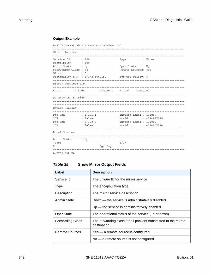
Mirroring
342
OAM and Diagnostics Guide
3HE 11013 AAAC TQZZA Edition: 01
Output Example
A:7705:Dut-B# show mirror mirror-dest 100===============================================================================Mirror Service===============================================================================Service Id : 100 Type : EtherDescription : 100Admin State : Up Oper State : UpForwarding Class : be Remote Sources: YesSlice : 0Destination SAP : 1/1/2:100.150 Egr QoS Policy: 3===============================================================================Mirror Services SDP===============================================================================SdpId IP Addr CfgLabel Signal EgrLabel-------------------------------------------------------------------------------No Matching Entries===============================================================================-------------------------------------------------------------------------------Remote Sources-------------------------------------------------------------------------------Far End : 1.1.1.1 Ingress Label : 131067ICB : false Vc-Id : 4294967295Far End : 3.3.3.3 Ingress Label : 131066ICB : false Vc-Id : 4294967294-------------------------------------------------------------------------------Local Sources-------------------------------------------------------------------------------Admin State : Up-Port 1/1/2 Egr Ing===============================================================================A:7705:Dut-B#
Table 35 Show Mirror Output Fields
Label Description
Service Id The unique ID for the mirror service
Type The encapsulation type
Description The mirror service description
Admin State Down — the service is administratively disabled
Up — the service is administratively enabled
Oper State The operational status of the service (up or down)
Forwarding Class The forwarding class for all packets transmitted to the mirror destination
Remote Sources Yes — a remote source is configured
No — a remote source is not configured
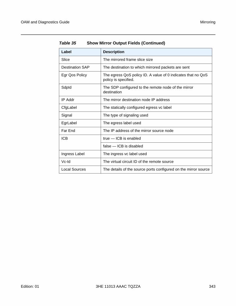
OAM and Diagnostics Guide Mirroring
Edition: 01 3HE 11013 AAAC TQZZA 343
Slice The mirrored frame slice size
Destination SAP The destination to which mirrored packets are sent
Egr Qos Policy The egress QoS policy ID. A value of 0 indicates that no QoS policy is specified.
SdpId The SDP configured to the remote node of the mirror destination
IP Addr The mirror destination node IP address
CfgLabel The statically configured egress vc label
Signal The type of signaling used
EgrLabel The egress label used
Far End The IP address of the mirror source node
ICB true — ICB is enabled
false — ICB is disabled
Ingress Label The ingress vc label used
Vc-Id The virtual circuit ID of the remote source
Local Sources The details of the source ports configured on the mirror source
Table 35 Show Mirror Output Fields (Continued)
Label Description
Mirroring
344
OAM and Diagnostics Guide
3HE 11013 AAAC TQZZA Edition: 01
4.7.2.3 Debug Commands
mirror-source
Syntax [no] mirror-source service-id
Context debug
Description This command configures mirror source parameters for a mirrored service.
The mirror-source command is used to enable mirroring of packets specified by the association of the mirror-source to sources of packets defined within the context of the mirror destination service ID. The mirror destination service must already exist within the system.
A mirrored packet cannot be mirrored to multiple destinations. If a packet matches multiple mirror source entries then the packet is mirrored to a single mirror destination service ID physical port. The precedence is structured so that the most specific match criteria has precedence over a less specific match.
The mirror-source configuration is not saved when a configuration is saved. A mirror-source manually configured within an ASCII configuration file will not be preserved if that file is overwritten by a save command. To make a mirror-source persistent between system reboots, you must define the mirror-source within a file associated with a config exec command.
By default, all mirror-dest service IDs have a mirror-source associated with them. The mirror-source is not technically created with this command. Instead, the service ID provides a contextual node for storing the current mirroring sources for the associated mirror-dest service ID. The mirror-source is created for the mirror service when the operator enters the debug>mirror-source service-id for the first time. The mirror-source is also automatically removed when the mirror-dest service ID is deleted from the system.
The no form of the command deletes all related source commands within the context of the mirror-source service-id. The command does not remove the service ID from the system.
Default n/a
Parameters service-id — the mirror destination service ID for which match criteria will be defined. The service-id must already exist within the system.
Values service-id: 1 to 2147483647 or svc-name
port
Syntax port {port-id | lag lag-id} {[egress] [ingress]}
no port {port-id | lag lag-id} [egress] [ingress]

OAM and Diagnostics Guide Mirroring
Edition: 01 3HE 11013 AAAC TQZZA 345
Context debug>mirror-source
Description This command enables mirroring of traffic ingressing or egressing an Ethernet port or Link Aggregation Group (LAG).
The port command associates a port or LAG with a mirror source. The port is identified by the port-id. The defined port can be an Ethernet access, network, or hybrid port. A network port may be a single port or a LAG ID. When a LAG ID is given as the port-id, mirroring is enabled on all ports making up the LAG.
The port is only referenced in the mirror source for mirroring purposes. If the port is removed from the system, the mirroring association will be removed from the mirror source.
The same port may not be associated with multiple mirror source definitions with the ingress parameter defined. The same port may not be associated with multiple mirror source definitions with the egress parameter defined.
If the port is not associated with a mirror-source, packets on that port will not be mirrored.
The no port command disables port mirroring for the specified port. Mirroring of packets on the port may continue due to more specific mirror criteria. If the egress or ingress parameter keywords are specified in the no command, only the ingress or egress mirroring condition will be removed.
Default n/a
Parameters port-id — the port ID
lag-id — the LAG identifier, expressed as a decimal integer
Values 1 to 32
egress — specifies that packets egressing the port should be mirrored. Egress packets are mirrored to the mirror destination after egress packet modification.
ingress — specifies that packets ingressing the port should be mirrored. Ingress packets are mirrored to the mirror destination prior to ingress packet modification.

Mirroring
346
OAM and Diagnostics Guide
3HE 11013 AAAC TQZZA Edition: 01
OAM and Diagnostics Guide Tools
Edition: 01 3HE 11013 AAAC TQZZA 347
5 Tools
5.1 Tools Command Reference
5.1.1 Command Hierarchies
• Tools Dump Commands
• Tools Perform Commands
• Tools ADP Commands
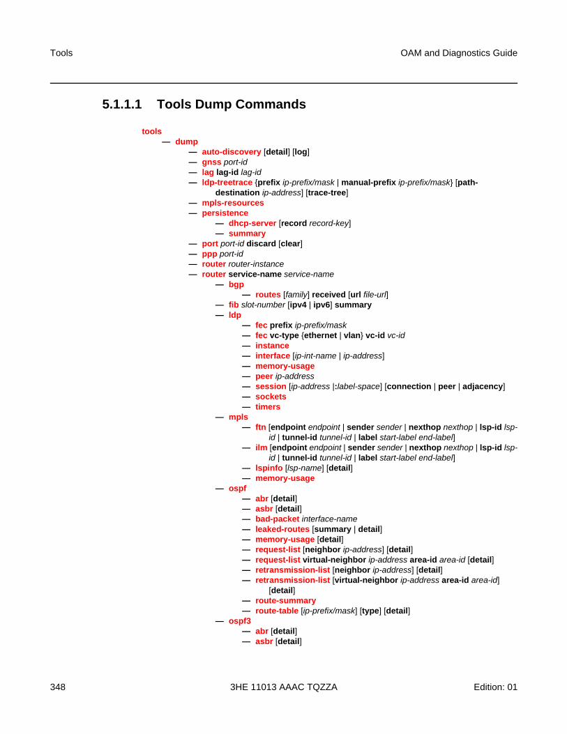
Tools
348
OAM and Diagnostics Guide
3HE 11013 AAAC TQZZA Edition: 01
5.1.1.1 Tools Dump Commands
tools— dump
— auto-discovery [detail] [log]— gnss port-id— lag lag-id lag-id— ldp-treetrace {prefix ip-prefix/mask | manual-prefix ip-prefix/mask} [path-
destination ip-address] [trace-tree]— mpls-resources— persistence
— dhcp-server [record record-key]— summary
— port port-id discard [clear]— ppp port-id— router router-instance— router service-name service-name
— bgp — routes [family] received [url file-url]
— fib slot-number [ipv4 | ipv6] summary — ldp
— fec prefix ip-prefix/mask— fec vc-type {ethernet | vlan} vc-id vc-id— instance — interface [ip-int-name | ip-address]— memory-usage— peer ip-address— session [ip-address |:label-space] [connection | peer | adjacency]— sockets — timers
— mpls— ftn [endpoint endpoint | sender sender | nexthop nexthop | lsp-id lsp-
id | tunnel-id tunnel-id | label start-label end-label]— ilm [endpoint endpoint | sender sender | nexthop nexthop | lsp-id lsp-
id | tunnel-id tunnel-id | label start-label end-label] — lspinfo [lsp-name] [detail]— memory-usage
— ospf— abr [detail]— asbr [detail]— bad-packet interface-name— leaked-routes [summary | detail]— memory-usage [detail]— request-list [neighbor ip-address] [detail]— request-list virtual-neighbor ip-address area-id area-id [detail]— retransmission-list [neighbor ip-address] [detail]— retransmission-list [virtual-neighbor ip-address area-id area-id]
[detail]— route-summary— route-table [ip-prefix/mask] [type] [detail]
— ospf3— abr [detail]— asbr [detail]
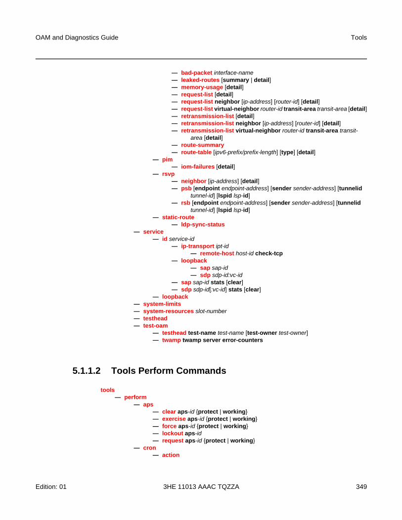
OAM and Diagnostics Guide Tools
Edition: 01 3HE 11013 AAAC TQZZA 349
— bad-packet interface-name— leaked-routes [summary | detail]— memory-usage [detail]— request-list [detail]— request-list neighbor [ip-address] [router-id] [detail]— request-list virtual-neighbor router-id transit-area transit-area [detail]— retransmission-list [detail]— retransmission-list neighbor [ip-address] [router-id] [detail]— retransmission-list virtual-neighbor router-id transit-area transit-
area [detail]— route-summary— route-table [ipv6-prefix/prefix-length] [type] [detail]
— pim— iom-failures [detail]
— rsvp— neighbor [ip-address] [detail]— psb [endpoint endpoint-address] [sender sender-address] [tunnelid
tunnel-id] [lspid lsp-id]— rsb [endpoint endpoint-address] [sender sender-address] [tunnelid
tunnel-id] [lspid lsp-id]— static-route
— ldp-sync-status— service
— id service-id— ip-transport ipt-id
— remote-host host-id check-tcp— loopback
— sap sap-id— sdp sdp-id:vc-id
— sap sap-id stats [clear]— sdp sdp-id[:vc-id] stats [clear]
— loopback — system-limits— system-resources slot-number— testhead— test-oam
— testhead test-name test-name [test-owner test-owner]— twamp twamp server error-counters
5.1.1.2 Tools Perform Commands
tools— perform
— aps— clear aps-id {protect | working}— exercise aps-id {protect | working}— force aps-id {protect | working}— lockout aps-id— request aps-id {protect | working}
— cron— action
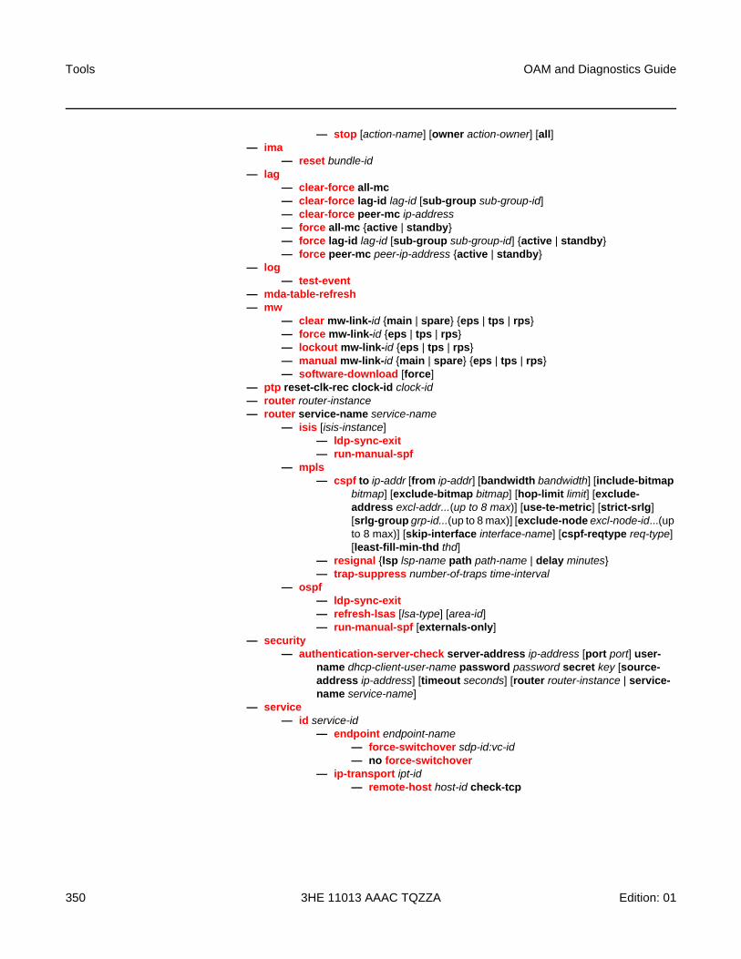
Tools
350
OAM and Diagnostics Guide
3HE 11013 AAAC TQZZA Edition: 01
— stop [action-name] [owner action-owner] [all]— ima
— reset bundle-id— lag
— clear-force all-mc— clear-force lag-id lag-id [sub-group sub-group-id] — clear-force peer-mc ip-address — force all-mc {active | standby}— force lag-id lag-id [sub-group sub-group-id] {active | standby}— force peer-mc peer-ip-address {active | standby}
— log— test-event
— mda-table-refresh— mw
— clear mw-link-id {main | spare} {eps | tps | rps}— force mw-link-id {eps | tps | rps}— lockout mw-link-id {eps | tps | rps}— manual mw-link-id {main | spare} {eps | tps | rps}— software-download [force]
— ptp reset-clk-rec clock-id clock-id— router router-instance— router service-name service-name
— isis [isis-instance] — ldp-sync-exit— run-manual-spf
— mpls — cspf to ip-addr [from ip-addr] [bandwidth bandwidth] [include-bitmap
bitmap] [exclude-bitmap bitmap] [hop-limit limit] [exclude-address excl-addr...(up to 8 max)] [use-te-metric] [strict-srlg] [srlg-group grp-id...(up to 8 max)] [exclude-node excl-node-id...(up to 8 max)] [skip-interface interface-name] [cspf-reqtype req-type] [least-fill-min-thd thd]
— resignal {lsp lsp-name path path-name | delay minutes}— trap-suppress number-of-traps time-interval
— ospf— ldp-sync-exit— refresh-lsas [lsa-type] [area-id]— run-manual-spf [externals-only]
— security— authentication-server-check server-address ip-address [port port] user-
name dhcp-client-user-name password password secret key [source-address ip-address] [timeout seconds] [router router-instance | service-name service-name]
— service— id service-id
— endpoint endpoint-name— force-switchover sdp-id:vc-id— no force-switchover
— ip-transport ipt-id— remote-host host-id check-tcp

OAM and Diagnostics Guide Tools
Edition: 01 3HE 11013 AAAC TQZZA 351
5.1.1.3 Tools ADP Commands
tools— auto-discovery [retry] [terminate]— [no] auto-discovery echo [debugger]
Tools
352
OAM and Diagnostics Guide
3HE 11013 AAAC TQZZA Edition: 01
5.1.2 Command Descriptions
• Tools Generic Commands
• Tools Dump Commands
• Tools Perform Commands
• Tools ADP Commands

OAM and Diagnostics Guide Tools
Edition: 01 3HE 11013 AAAC TQZZA 353
5.1.2.1 Tools Generic Commands
tools
Syntax tools
Context <root>
Description This command enables the context to use tools for debugging purposes.
Default n/a

Tools
354
OAM and Diagnostics Guide
3HE 11013 AAAC TQZZA Edition: 01
5.1.2.2 Tools Dump Commands
• Dump Commands
• Dump Test-OAM Commands
• Dump Router Commands

OAM and Diagnostics Guide Tools
Edition: 01 3HE 11013 AAAC TQZZA 355
5.1.2.2.1 Dump Commands
dump
Syntax dump
Context tools
Description This command enables the context to display information for debugging purposes.
Default n/a
auto-discovery
Syntax auto-discovery [detail] [log]
Context tools>dump
Description This command allows you to view all progress and event logs stored by ADP.
Default n/a
Parameters detail — displays detailed information about the system, ports, and ADP instructions
log — displays all detailed progress and event logs with timestamps
gnss
Syntax gnss port-id
Context tools>dump
Description This command displays GNSS satellite signal strength information.
Default n/a
Parameters port-id — specifies the port ID in the format slot/mda/port
Output The following output is an example of GNSS information.
Output Example
A:ALU-1># tools dump gnss 1/3/1======================Satellites======================SVID Signal-Strength
C/No (dB-Hz)----------------------
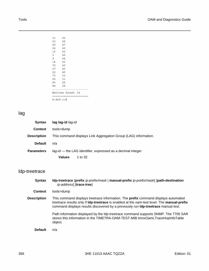
Tools
356
OAM and Diagnostics Guide
3HE 11013 AAAC TQZZA Edition: 01
31 5023 4829 4726 4516 453 459 4414 4274 4027 4022 4075 3365 3183 2684 24----------------------Entries found: 15======================A:ALU-1>#
lag
Syntax lag lag-id lag-id
Context tools>dump
Description This command displays Link Aggregation Group (LAG) information.
Default n/a
Parameters lag-id — the LAG identifier, expressed as a decimal integer
Values 1 to 32
ldp-treetrace
Syntax ldp-treetrace {prefix ip-prefix/mask | manual-prefix ip-prefix/mask} [path-destination ip-address] [trace-tree]
Context tools>dump
Description This command displays treetrace information. The prefix command displays automated treetrace results only if ldp-treetrace is enabled at the oam-test level. The manual-prefix command displays results discovered by a previously run ldp-treetrace manual test.
Path information displayed by the ldp-treetrace command supports SNMP. The 7705 SAR stores this information in the TIMETRA-OAM-TEST-MIB tmnxOamLTraceHopInfoTable object.
Default n/a
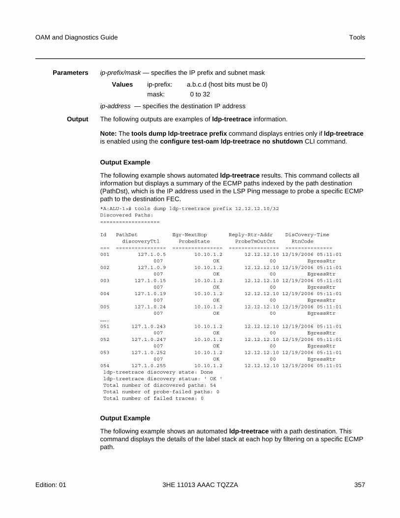
OAM and Diagnostics Guide Tools
Edition: 01 3HE 11013 AAAC TQZZA 357
Parameters ip-prefix/mask — specifies the IP prefix and subnet mask
Values ip-prefix: a.b.c.d (host bits must be 0)
mask: 0 to 32
ip-address — specifies the destination IP address
Output The following outputs are examples of ldp-treetrace information.
Note: The tools dump ldp-treetrace prefix command displays entries only if ldp-treetrace is enabled using the configure test-oam ldp-treetrace no shutdown CLI command.
Output Example
The following example shows automated ldp-treetrace results. This command collects all information but displays a summary of the ECMP paths indexed by the path destination (PathDst), which is the IP address used in the LSP Ping message to probe a specific ECMP path to the destination FEC.*A:ALU-1># tools dump ldp-treetrace prefix 12.12.12.10/32Discovered Paths:===================
Id PathDst Egr-NextHop Reply-Rtr-Addr DisCovery-TimediscoveryTtl ProbeState ProbeTmOutCnt RtnCode
=== ================ ================ ================ ===============001 127.1.0.5 10.10.1.2 12.12.12.10 12/19/2006 05:11:01
007 OK 00 EgressRtr002 127.1.0.9 10.10.1.2 12.12.12.10 12/19/2006 05:11:01
007 OK 00 EgressRtr003 127.1.0.15 10.10.1.2 12.12.12.10 12/19/2006 05:11:01
007 OK 00 EgressRtr004 127.1.0.19 10.10.1.2 12.12.12.10 12/19/2006 05:11:01
007 OK 00 EgressRtr005 127.1.0.24 10.10.1.2 12.12.12.10 12/19/2006 05:11:01
007 OK 00 EgressRtr…….051 127.1.0.243 10.10.1.2 12.12.12.10 12/19/2006 05:11:01
007 OK 00 EgressRtr052 127.1.0.247 10.10.1.2 12.12.12.10 12/19/2006 05:11:01
007 OK 00 EgressRtr053 127.1.0.252 10.10.1.2 12.12.12.10 12/19/2006 05:11:01
007 OK 00 EgressRtr054 127.1.0.255 10.10.1.2 12.12.12.10 12/19/2006 05:11:01ldp-treetrace discovery state: Doneldp-treetrace discovery status: ' OK 'Total number of discovered paths: 54Total number of probe-failed paths: 0Total number of failed traces: 0
Output Example
The following example shows an automated ldp-treetrace with a path destination. This command displays the details of the label stack at each hop by filtering on a specific ECMP path.
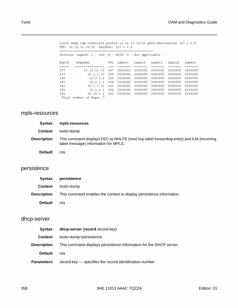
Tools
358
OAM and Diagnostics Guide
3HE 11013 AAAC TQZZA Edition: 01
tools dump ldp-treetrace prefix 12.12.12.10/32 path-destination 127.1.0.5FEC: 12.12.12.10/32 PathDst: 127.1.0.5==================================================Protocol Legend: L - LDP, R - RSVP, U - Not Applicable
HopId HopAddr TTL Label1 Label2 Label3 Label4 Label5===== ================ === ======= ======= ======= ======= =======277 12.12.12.10 007 000000L 000000U 000000U 000000U 000000U223 10.1.1.17 006 001609L 000000U 000000U 000000U 000000U196 10.2.1.2 005 001609L 000000U 000000U 000000U 000000U187 10.2.1.1 004 001609L 000000U 000000U 000000U 000000U184 10.1.1.11 003 001609L 000000U 000000U 000000U 000000U183 10.1.1.1 002 001609L 000000U 000000U 000000U 000000U182 10.10.1.2 001 001609L 000000U 000000U 000000U 000000UTotal number of Hops: 7
mpls-resources
Syntax mpls-resources
Context tools>dump
Description This command displays FEC-to-NHLFE (next hop label forwarding entry) and ILM (incoming label message) information for MPLS.
Default n/a
persistence
Syntax persistence
Context tools>dump
Description This command enables the context to display persistence information.
Default n/a
dhcp-server
Syntax dhcp-server [record record-key]
Context tools>dump>persistence
Description This command displays persistence information for the DHCP server.
Default n/a
Parameters record-key — specifies the record identification number
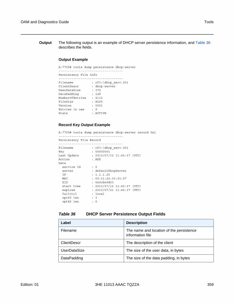
OAM and Diagnostics Guide Tools
Edition: 01 3HE 11013 AAAC TQZZA 359
Output The following output is an example of DHCP server persistence information, and Table 36 describes the fields.
Output Example
A:7705# tools dump persistence dhcp-server-----------------------------------Persistency File Info-----------------------------------Filename : cf3:\dhcp_serv.001ClientDescr : dhcp-serverUserDataSize : 372DataPadding : 128NumberOfEntries : 4112FileSize : 8225Version : 0001Entries in use : 9State : ACTIVE
Record Key Output Example
A:7705# tools dump persistence dhcp-server record 0x1-----------------------------------Persistency File Record-----------------------------------Filename : cf3:\dhcp_serv.001Key : 00000001Last Update : 2013/07/12 11:45:37 (UTC)Action : ADDData
service Id : 0server : defaultDhcpServerIP : 1.1.1.20MAC : 00:11:22:33:01:07XID : 0x0cbe9d53start time : 2013/07/12 11:45:37 (UTC)expires : 2013/07/21 11:45:37 (UTC)failctrl : localopt60 len : 3opt82 len : 0
Table 36 DHCP Server Persistence Output Fields
Label Description
Filename The name and location of the persistence information file
ClientDescr The description of the client
UserDataSize The size of the user data, in bytes
DataPadding The size of the data padding, in bytes
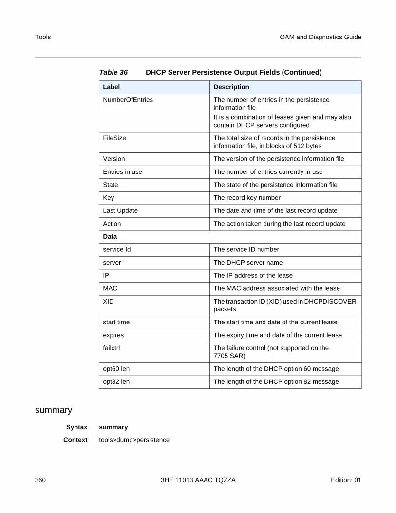
Tools
360
OAM and Diagnostics Guide
3HE 11013 AAAC TQZZA Edition: 01
summary
Syntax summary
Context tools>dump>persistence
NumberOfEntries The number of entries in the persistence information file
It is a combination of leases given and may also contain DHCP servers configured
FileSize The total size of records in the persistence information file, in blocks of 512 bytes
Version The version of the persistence information file
Entries in use The number of entries currently in use
State The state of the persistence information file
Key The record key number
Last Update The date and time of the last record update
Action The action taken during the last record update
Data
service Id The service ID number
server The DHCP server name
IP The IP address of the lease
MAC The MAC address associated with the lease
XID The transaction ID (XID) used in DHCPDISCOVER packets
start time The start time and date of the current lease
expires The expiry time and date of the current lease
failctrl The failure control (not supported on the 7705 SAR)
opt60 len The length of the DHCP option 60 message
opt82 len The length of the DHCP option 82 message
Table 36 DHCP Server Persistence Output Fields (Continued)
Label Description
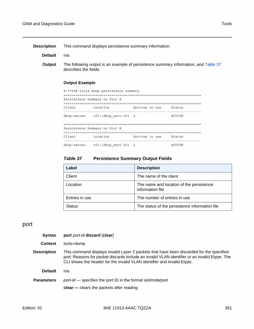
OAM and Diagnostics Guide Tools
Edition: 01 3HE 11013 AAAC TQZZA 361
Description This command displays persistence summary information.
Default n/a
Output The following output is an example of persistence summary information, and Table 37 describes the fields.
Output Example
A:7705# tools dump persistence summary=====================================================================Persistence Summary on Slot A=====================================================================Client Location Entries in use Status---------------------------------------------------------------------dhcp-server cf3:\dhcp_serv.001 2 ACTIVE
=====================================================================Persistence Summary on Slot B=====================================================================Client Location Entries in use Status---------------------------------------------------------------------dhcp-server cf3:\dhcp_serv.001 2 ACTIVE
port
Syntax port port-id discard [clear]
Context tools>dump
Description This command displays invalid Layer 2 packets that have been discarded for the specified port. Reasons for packet discards include an invalid VLAN identifier or an invalid Etype. The CLI shows the header for the invalid VLAN identifier and invalid Etype.
Default n/a
Parameters port-id — specifies the port ID in the format slot/mda/port
clear — clears the packets after reading
Table 37 Persistence Summary Output Fields
Label Description
Client The name of the client
Location The name and location of the persistence information file
Entries in use The number of entries in use
Status The status of the persistence information file
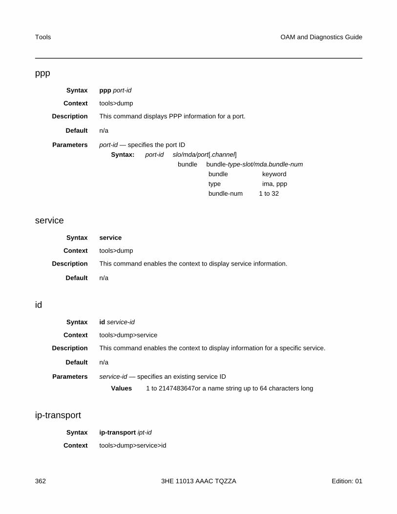
Tools
362
OAM and Diagnostics Guide
3HE 11013 AAAC TQZZA Edition: 01
ppp
Syntax ppp port-id
Context tools>dump
Description This command displays PPP information for a port.
Default n/a
Parameters port-id — specifies the port ID
Syntax: port-id slo/mda/port[.channel]
bundle bundle-type-slot/mda.bundle-num
bundle keyword
type ima, ppp
bundle-num 1 to 32
service
Syntax service
Context tools>dump
Description This command enables the context to display service information.
Default n/a
id
Syntax id service-id
Context tools>dump>service
Description This command enables the context to display information for a specific service.
Default n/a
Parameters service-id — specifies an existing service ID
Values 1 to 2147483647or a name string up to 64 characters long
ip-transport
Syntax ip-transport ipt-id
Context tools>dump>service>id
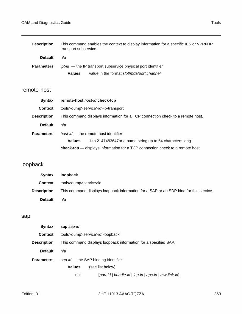
OAM and Diagnostics Guide Tools
Edition: 01 3HE 11013 AAAC TQZZA 363
Description This command enables the context to display information for a specific IES or VPRN IP transport subservice.
Default n/a
Parameters ipt-id — the IP transport subservice physical port identifier
Values value in the format slot/mda/port.channel
remote-host
Syntax remote-host host-id check-tcp
Context tools>dump>service>id>ip-transport
Description This command displays information for a TCP connection check to a remote host.
Default n/a
Parameters host-id — the remote host identifier
Values 1 to 2147483647or a name string up to 64 characters long
check-tcp — displays information for a TCP connection check to a remote host
loopback
Syntax loopback
Context tools>dump>service>id
Description This command displays loopback information for a SAP or an SDP bind for this service.
Default n/a
sap
Syntax sap sap-id
Context tools>dump>service>id>loopback
Description This command displays loopback information for a specified SAP.
Default n/a
Parameters sap-id — the SAP binding identifier
Values (see list below)
null [port-id | bundle-id | lag-id | aps-id | mw-link-id]
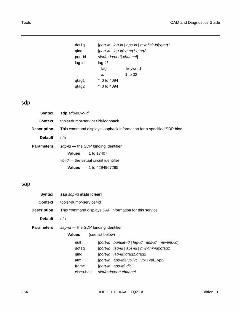
Tools
364
OAM and Diagnostics Guide
3HE 11013 AAAC TQZZA Edition: 01
sdp
Syntax sdp sdp-id:vc-id
Context tools>dump>service>id>loopback
Description This command displays loopback information for a specified SDP bind.
Default n/a
Parameters sdp-id — the SDP binding identifier
Values 1 to 17407
vc-id — the virtual circuit identifier
Values 1 to 4294967295
sap
Syntax sap sdp-id stats [clear]
Context tools>dump>service>id
Description This command displays SAP information for this service.
Default n/a
Parameters sap-id — the SDP binding identifier
Values (see list below)
dot1q [port-id | lag-id | aps-id | mw-link-id]:qtag1
qinq [port-id | lag-id]:qtag1.qtag2
port-id slot/mda/port[.channel]
lag-id lag-id
lag keyword
id 1 to 32
qtag1 *, 0 to 4094
qtag2 *, 0 to 4094
null [port-id | bundle-id | lag-id | aps-id | mw-link-id]
dot1q [port-id | lag-id | aps-id | mw-link-id]:qtag1
qinq [port-id | lag-id]:qtag1.qtag2
atm [port-id | aps-id][:vpi/vci |vpi | vpi1.vpi2]
frame [port-id | aps-id]:dlci
cisco-hdlc slot/mda/port.channel
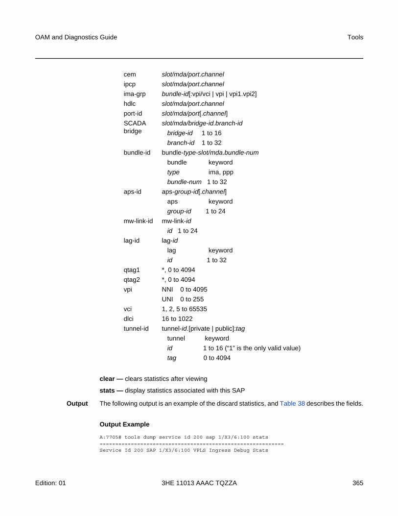
OAM and Diagnostics Guide Tools
Edition: 01 3HE 11013 AAAC TQZZA 365
clear — clears statistics after viewing
stats — display statistics associated with this SAP
Output The following output is an example of the discard statistics, and Table 38 describes the fields.
Output Example
A:7705# tools dump service id 200 sap 1/X3/6:100 stats===========================================================Service Id 200 SAP 1/X3/6:100 VPLS Ingress Debug Stats
cem slot/mda/port.channel
ipcp slot/mda/port.channel
ima-grp bundle-id[:vpi/vci | vpi | vpi1.vpi2]
hdlc slot/mda/port.channel
port-id slot/mda/port[.channel]
SCADA bridge
slot/mda/bridge-id.branch-id
bridge-id 1 to 16
branch-id 1 to 32
bundle-id bundle-type-slot/mda.bundle-num
bundle keyword
type ima, ppp
bundle-num 1 to 32
aps-id aps-group-id[.channel]
aps keyword
group-id 1 to 24
mw-link-id mw-link-id
id 1 to 24
lag-id lag-id
lag keyword
id 1 to 32
qtag1 *, 0 to 4094
qtag2 *, 0 to 4094
vpi NNI 0 to 4095
UNI 0 to 255
vci 1, 2, 5 to 65535
dlci 16 to 1022
tunnel-id tunnel-id.[private | public]:tag
tunnel keyword
id 1 to 16 (“1” is the only valid value)
tag 0 to 4094
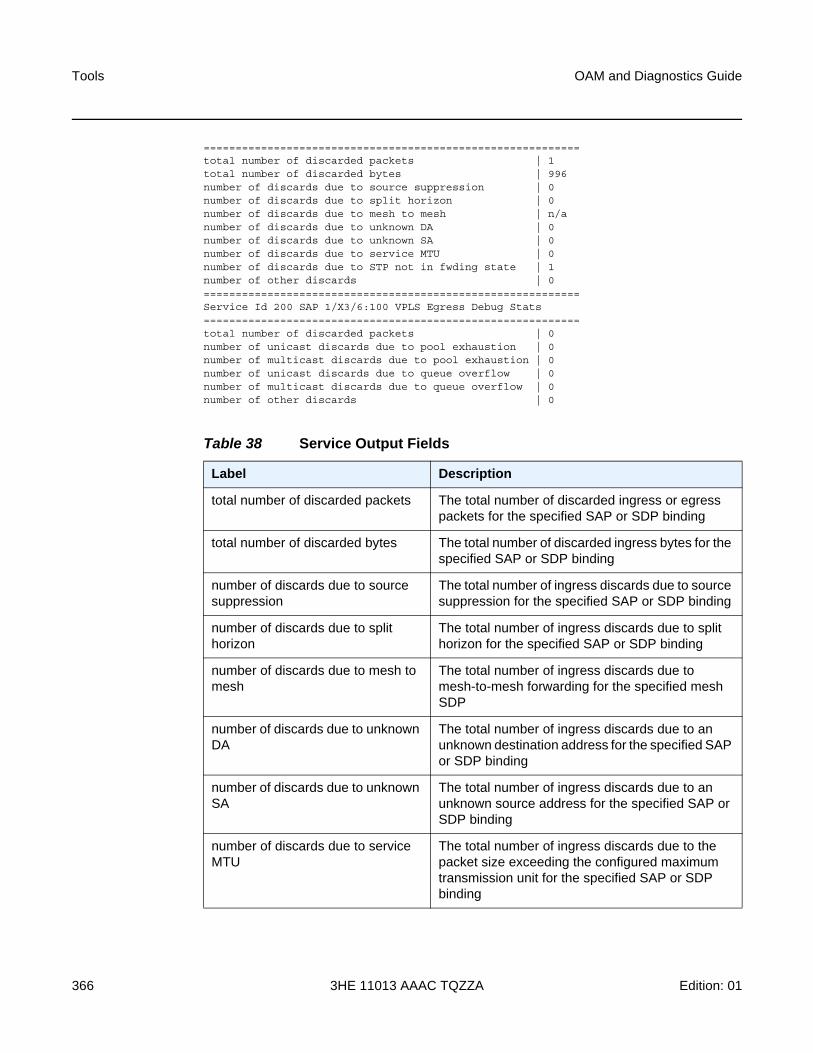
Tools
366
OAM and Diagnostics Guide
3HE 11013 AAAC TQZZA Edition: 01
===========================================================total number of discarded packets | 1total number of discarded bytes | 996number of discards due to source suppression | 0number of discards due to split horizon | 0number of discards due to mesh to mesh | n/anumber of discards due to unknown DA | 0number of discards due to unknown SA | 0number of discards due to service MTU | 0number of discards due to STP not in fwding state | 1number of other discards | 0===========================================================Service Id 200 SAP 1/X3/6:100 VPLS Egress Debug Stats===========================================================total number of discarded packets | 0number of unicast discards due to pool exhaustion | 0number of multicast discards due to pool exhaustion | 0number of unicast discards due to queue overflow | 0number of multicast discards due to queue overflow | 0number of other discards | 0
Table 38 Service Output Fields
Label Description
total number of discarded packets The total number of discarded ingress or egress packets for the specified SAP or SDP binding
total number of discarded bytes The total number of discarded ingress bytes for the specified SAP or SDP binding
number of discards due to source suppression
The total number of ingress discards due to source suppression for the specified SAP or SDP binding
number of discards due to split horizon
The total number of ingress discards due to split horizon for the specified SAP or SDP binding
number of discards due to mesh to mesh
The total number of ingress discards due to mesh-to-mesh forwarding for the specified mesh SDP
number of discards due to unknown DA
The total number of ingress discards due to an unknown destination address for the specified SAP or SDP binding
number of discards due to unknown SA
The total number of ingress discards due to an unknown source address for the specified SAP or SDP binding
number of discards due to service MTU
The total number of ingress discards due to the packet size exceeding the configured maximum transmission unit for the specified SAP or SDP binding
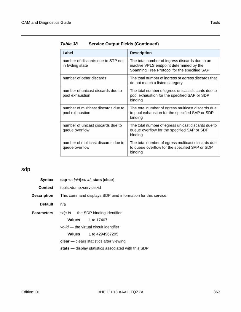
OAM and Diagnostics Guide Tools
Edition: 01 3HE 11013 AAAC TQZZA 367
sdp
Syntax sap <sdpid[:vc-id] stats [clear]
Context tools>dump>service>id
Description This command displays SDP bind information for this service.
Default n/a
Parameters sdp-id — the SDP binding identifier
Values 1 to 17407
vc-id — the virtual circuit identifier
Values 1 to 4294967295
clear — clears statistics after viewing
stats — display statistics associated with this SDP
number of discards due to STP not in fwding state
The total number of ingress discards due to an inactive VPLS endpoint determined by the Spanning Tree Protocol for the specified SAP
number of other discards The total number of ingress or egress discards that do not match a listed category
number of unicast discards due to pool exhaustion
The total number of egress unicast discards due to pool exhaustion for the specified SAP or SDP binding
number of multicast discards due to pool exhaustion
The total number of egress multicast discards due to pool exhaustion for the specified SAP or SDP binding
number of unicast discards due to queue overflow
The total number of egress unicast discards due to queue overflow for the specified SAP or SDP binding
number of multicast discards due to queue overflow
The total number of egress multicast discards due to queue overflow for the specified SAP or SDP binding
Table 38 Service Output Fields (Continued)
Label Description
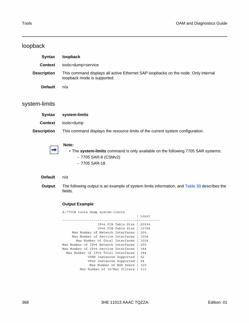
Tools
368
OAM and Diagnostics Guide
3HE 11013 AAAC TQZZA Edition: 01
loopback
Syntax loopback
Context tools>dump>service
Description This command displays all active Ethernet SAP loopbacks on the node. Only internal loopback mode is supported.
Default n/a
system-limits
Syntax system-limits
Context tools>dump
Description This command displays the resource limits of the current system configuration.
Default n/a
Output The following output is an example of system limits information, and Table 39 describes the fields.
Output Example
A:7705# tools dump system-limits| Limit
--------------------------------------+-----------IPv4 FIB Table Size | 65536IPv6 FIB Table Size | 32768
Max Number of Network Interfaces | 256Max Number of Service Interfaces | 1024
Max Number of Total Interfaces | 1024Max Number of IPv6 Network Interfaces | 255Max Number of IPv6 Service Interfaces | 384
Max Number of IPv6 Total Interfaces | 384VPRN Instances Supported | 62VPLS Instances Supported | 64Max Number of BGP Peers | 320
Max Number of IP/Mac Filters | 512
Note:
• The system-limits command is only available on the following 7705 SAR systems:
− 7705 SAR-8 (CSMv2)
− 7705 SAR-18
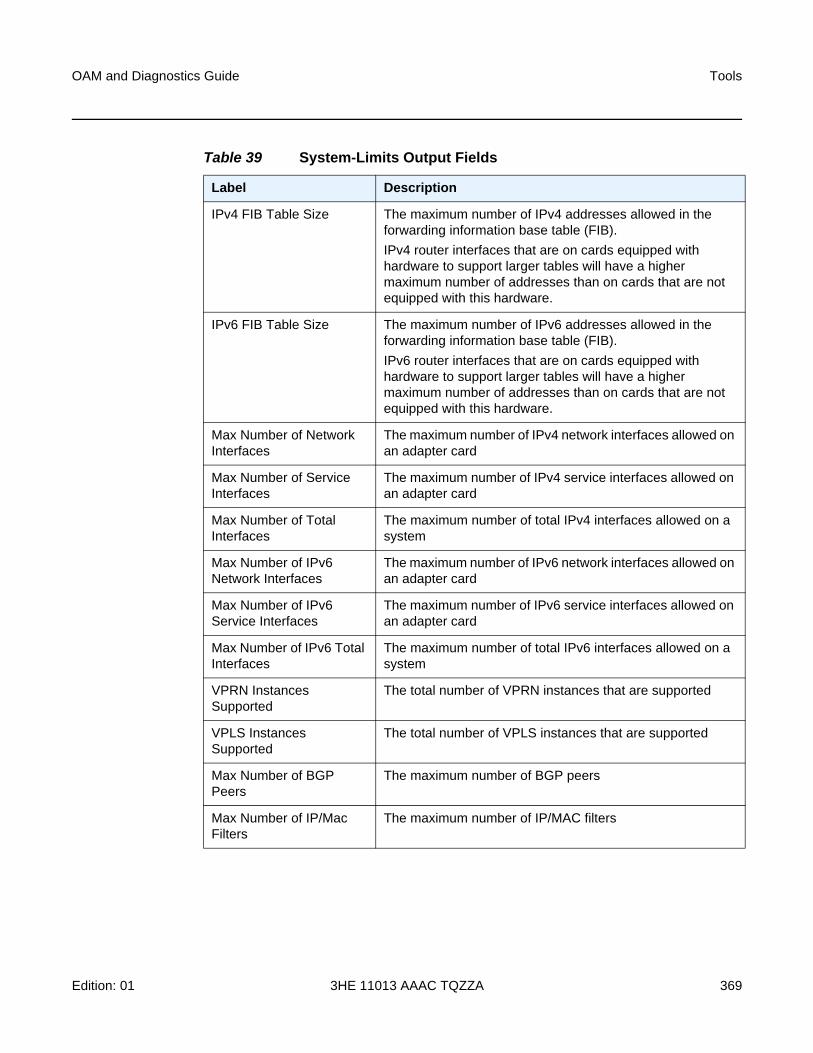
OAM and Diagnostics Guide Tools
Edition: 01 3HE 11013 AAAC TQZZA 369
Table 39 System-Limits Output Fields
Label Description
IPv4 FIB Table Size The maximum number of IPv4 addresses allowed in the forwarding information base table (FIB).
IPv4 router interfaces that are on cards equipped with hardware to support larger tables will have a higher maximum number of addresses than on cards that are not equipped with this hardware.
IPv6 FIB Table Size The maximum number of IPv6 addresses allowed in the forwarding information base table (FIB).
IPv6 router interfaces that are on cards equipped with hardware to support larger tables will have a higher maximum number of addresses than on cards that are not equipped with this hardware.
Max Number of Network Interfaces
The maximum number of IPv4 network interfaces allowed on an adapter card
Max Number of Service Interfaces
The maximum number of IPv4 service interfaces allowed on an adapter card
Max Number of Total Interfaces
The maximum number of total IPv4 interfaces allowed on a system
Max Number of IPv6 Network Interfaces
The maximum number of IPv6 network interfaces allowed on an adapter card
Max Number of IPv6 Service Interfaces
The maximum number of IPv6 service interfaces allowed on an adapter card
Max Number of IPv6 Total Interfaces
The maximum number of total IPv6 interfaces allowed on a system
VPRN Instances Supported
The total number of VPRN instances that are supported
VPLS Instances Supported
The total number of VPLS instances that are supported
Max Number of BGP Peers
The maximum number of BGP peers
Max Number of IP/Mac Filters
The maximum number of IP/MAC filters
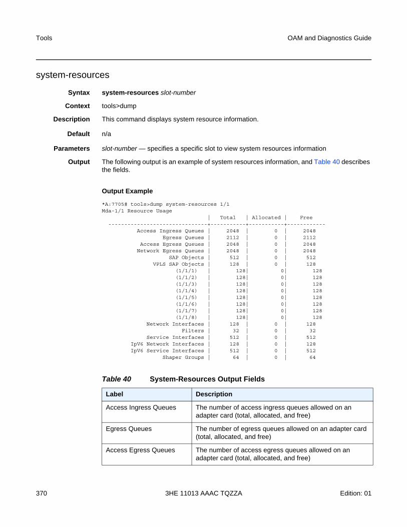
Tools
370
OAM and Diagnostics Guide
3HE 11013 AAAC TQZZA Edition: 01
system-resources
Syntax system-resources slot-number
Context tools>dump
Description This command displays system resource information.
Default n/a
Parameters slot-number — specifies a specific slot to view system resources information
Output The following output is an example of system resources information, and Table 40 describes the fields.
Output Example
*A:7705# tools>dump system-resources 1/1Mda-1/1 Resource Usage
| Total | Allocated | Free-------------------------------+-----------+-----------+------------
Access Ingress Queues | 2048 | 0 | 2048Egress Queues | 2112 | 0 | 2112
Access Egress Queues | 2048 | 0 | 2048Network Egress Queues | 2048 | 0 | 2048
SAP Objects | 512 | 0 | 512VPLS SAP Objects | 128 | 0 | 128
(1/1/1) | 128| 0| 128(1/1/2) | 128| 0| 128(1/1/3) | 128| 0| 128(1/1/4) | 128| 0| 128(1/1/5) | 128| 0| 128(1/1/6) | 128| 0| 128(1/1/7) | 128| 0| 128(1/1/8) | 128| 0| 128
Network Interfaces | 128 | 0 | 128Filters | 32 | 0 | 32
Service Interfaces | 512 | 0 | 512IpV6 Network Interfaces | 128 | 0 | 128IpV6 Service Interfaces | 512 | 0 | 512
Shaper Groups | 64 | 0 | 64
Table 40 System-Resources Output Fields
Label Description
Access Ingress Queues The number of access ingress queues allowed on an adapter card (total, allocated, and free)
Egress Queues The number of egress queues allowed on an adapter card (total, allocated, and free)
Access Egress Queues The number of access egress queues allowed on an adapter card (total, allocated, and free)
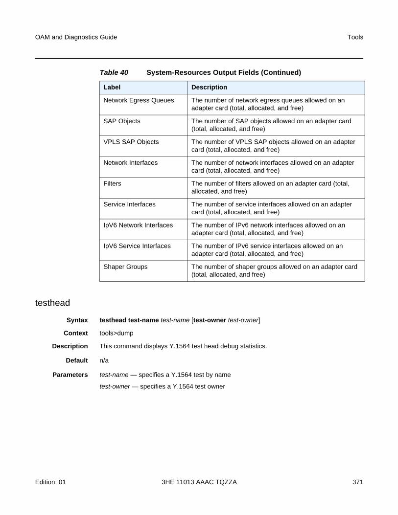
OAM and Diagnostics Guide Tools
Edition: 01 3HE 11013 AAAC TQZZA 371
testhead
Syntax testhead test-name test-name [test-owner test-owner]
Context tools>dump
Description This command displays Y.1564 test head debug statistics.
Default n/a
Parameters test-name — specifies a Y.1564 test by name
test-owner — specifies a Y.1564 test owner
Network Egress Queues The number of network egress queues allowed on an adapter card (total, allocated, and free)
SAP Objects The number of SAP objects allowed on an adapter card (total, allocated, and free)
VPLS SAP Objects The number of VPLS SAP objects allowed on an adapter card (total, allocated, and free)
Network Interfaces The number of network interfaces allowed on an adapter card (total, allocated, and free)
Filters The number of filters allowed on an adapter card (total, allocated, and free)
Service Interfaces The number of service interfaces allowed on an adapter card (total, allocated, and free)
IpV6 Network Interfaces The number of IPv6 network interfaces allowed on an adapter card (total, allocated, and free)
IpV6 Service Interfaces The number of IPv6 service interfaces allowed on an adapter card (total, allocated, and free)
Shaper Groups The number of shaper groups allowed on an adapter card (total, allocated, and free)
Table 40 System-Resources Output Fields (Continued)
Label Description

Tools
372
OAM and Diagnostics Guide
3HE 11013 AAAC TQZZA Edition: 01
5.1.2.2.2 Dump Test-OAM Commands
test-oam
Syntax test-oam
Context tools>dump
Description This command enables the context to display operations, administration, and maintenance information.
Default n/a
testhead
Syntax testhead test-name test-name [test-owner test-owner]
Context tools>dump>test-oam
Description This command displays Y.1564 test head debug statistics.
Default n/a
Parameters name-of-the-test — the name of the Y.1564 test
owner-of-the-test — the owner of the Y.1564 test
twamp
Syntax server error-counters
Context tools>dump>test-oam
Description This command displays server information, specifically the number of protocol errors, for the TWAMP server. The output includes statistics for dropped connections, dropped connection states, rejected sessions, and dropped test packets.
Default n/a
OAM and Diagnostics Guide Tools
Edition: 01 3HE 11013 AAAC TQZZA 373
5.1.2.2.3 Dump Router Commands
router
Syntax router router-instance
router service-name service-name
Context tools>dump
Description This command enables tools for the router instance.
Default n/a
Parameters router-instance — specifies the router name and service ID
Values router-name: Base, management
service-id: 1 to 2147483647
Default Base
service-name — specifies the service name
bgp
Syntax bgp
Context tools>dump>router
Description This command enables dump tools for BGP.
Default n/a
routes
Syntax routes [family] received [url file-url]
Context tools>dump>router>bgp
Description This command displays information for BGP routes.
Default n/a
Parameters received — displays information about received routes
family — specifies the family for which information is displayed
Values ipv4, vpn-ipv4, ipv6, vpn-ipv6, or mvpn-ipv4
Tools
374
OAM and Diagnostics Guide
3HE 11013 AAAC TQZZA Edition: 01
url file-url — the URL of the file
Values
fib
Syntax fib slot-number [ipv4 | ipv6] summary
Context tools>dump>router
Description This command displays information for the FIB.
Default n/a
Parameters slot-number — specifies the slot number, always “1”
ipv4 | ipv6 — specifies the IP family
summary — displays summary information
file-url : local-url | remote-url
local-url : [cflash-id/][file-path]
200 chars max, including cflash-id
directory length 99 chars max each
remote-url : [{ftp:// | tftp://}login:pswd@remote- locn][file-path]
255 chars max
directory length 99 chars max each
remote-locn : [hostname | ipv4-address | ipv6-address]
ipv4-address : a.b.c.d
ipv6-address : x:x:x:x:x:x:x:x[-interface]
x:x:x:x:x:x:d.d.d.d[-interface]
x: [0..FFFF]H
d: [0..255]D
interface: 32 chars max, for link local addresses
cflash-id : (7705 SAR-18) cf1: | cf1-A: | cf1-B: | cf2: | cf2-A: | cf2-B: | cf3: | cf3-A: | cf3-B:
(7705 SAR-8) cf3: | cf3-A: | cf3-B:
(7705 SAR fixed platforms) cf3: | cf3-A:
OAM and Diagnostics Guide Tools
Edition: 01 3HE 11013 AAAC TQZZA 375
ldp
Syntax ldp
Context tools>dump>router
Description This command enables dump tools for LDP.
Default n/a
fec
Syntax fec prefix ip-prefix/mask
fec vc-type {ethernet | vlan} vc-id vc-id
Context tools>dump>router>ldp
Description This command displays information for an LDP FEC.
Default n/a
Parameters ip-prefix/mask — specifies the IP prefix and subnet mask
Values ip-prefix: a.b.c.d (host bits must be 0)
mask: 0 to 32
vc-type — specifies the VC type signaled for the spoke or mesh binding to the far end of an SDP. The VC type is a 15-bit quantity containing a value that represents the type of VC. The actual signaling of the VC type depends on the signaling parameter defined for the SDP. If signaling is disabled, the vc-type command can still be used to define the dot1q value expected by the far-end provider equipment. A change of the binding’s VC type causes the binding to signal the new VC type to the far end when signaling is enabled.
VC types are derived according to IETF draft-martini-l2circuit-trans-mpls.
Values Ethernet — 0x0005
VLAN — 0x0004
vc-id — specifies the virtual circuit identifier
Values 1 to 4294967295
instance
Syntax instance
Context tools>dump>router>ldp
Description This command displays information for an LDP instance.
Tools
376
OAM and Diagnostics Guide
3HE 11013 AAAC TQZZA Edition: 01
Default n/a
interface
Syntax interface [ip-int-name | ip-address]
Context tools>dump>router>ldp
Description This command displays information for an LDP interface.
Default n/a
Parameters ip-int-name — specifies the interface name
ip-address — specifies the IP address
memory-usage
Syntax memory-usage
Context tools>dump>router>ldp
Description This command displays memory usage information for LDP.
Default n/a
peer
Syntax peer ip-address
Context tools>dump>router>ldp
Description This command displays information for an LDP peer.
Default n/a
Parameters ip-address — specifies the IP address
session
Syntax session [ip-address |:label space] [connection | peer | adjacency]
Context tools>dump>router>ldp
Description This command displays information for an LDP session.
Default n/a
OAM and Diagnostics Guide Tools
Edition: 01 3HE 11013 AAAC TQZZA 377
Parameters ip-address — specifies the IP address of the LDP peer
label-space — specifies the label space identifier that the router is advertising on the interface
connection — displays connection information
peer — displays peer information
adjacency — displays hello adjacency information
sockets
Syntax sockets
Context tools>dump>router>ldp
Description This command displays information for all sockets being used by the LDP protocol.
Default n/a
timers
Syntax timers
Context tools>dump>router>ldp
Description This command displays timer information for LDP.
Default n/a
mpls
Syntax mpls
Context tools>dump>router
Description This command enables the context to display MPLS information.
Default n/a
ftn
Syntax ftn [endpoint endpoint | sender sender | nexthop nexthop | lsp-id lsp-id | tunnel-id tunnel-id | label start-label end-label]
Context tools>dump>router>mpls
Tools
378
OAM and Diagnostics Guide
3HE 11013 AAAC TQZZA Edition: 01
Description This command displays FEC-to-NHLFE (FTN) dump information for MPLS. (NHLFE is the acronym for Next Hop Label Forwarding Entry.)
Default n/a
Parameters endpoint — specifies the IP address of the last hop
Values a.b.c.d
sender — specifies the IP address of the sender
Values a.b.c.d
nexthop — specifies the IP address of the next hop
Values a.b.c.d
lsp-id — specifies the label switched path that is signaled for this entry
Values 0 to 65535
tunnel-id — specifies the SDP ID
Values 0 to 65535
start-label end-label — specifies the label range for the information dump
Values start-label — 32 to 131071
end-label — 32 to 131071
ilm
Syntax ilm [endpoint endpoint | sender sender | nexthop nexthop | lsp-id lsp-id | tunnel-id tunnel-id | label start-label end-label]
Context tools>dump>router>mpls
Description This command displays incoming label map (ILM) information for MPLS.
Default n/a
Parameters endpoint — specifies the IP address of the last hop
Values a.b.c.d
sender — specifies the IP address of the sender
Values a.b.c.d
nexthop — specifies the IP address of the next hop
Values a.b.c.d
lsp-id — specifies the label switched path that is signaled for this entry
Values 0 to 65535
OAM and Diagnostics Guide Tools
Edition: 01 3HE 11013 AAAC TQZZA 379
tunnel-id — specifies the SDP ID
Values 0 to 65535
start-label end-label — specifies the label range for the information dump
Values start-label — 32 to 131071
end-label — 32 to 131071
lspinfo
Syntax lspinfo [lsp-name] [detail]
Context tools>dump>router>mpls
Description This command displays LSP information for MPLS.
Default n/a
Parameters lsp-name — the LSP identifier
Values up to 32 characters (must be unique)
detail — displays detailed LSP information
memory-usage
Syntax memory-usage
Context tools>dump>router>mpls
Description This command displays memory usage information for MPLS.
Default n/a
ospf
Syntax ospf
Context tools>dump>router
Description This command enables the context to display tools information for OSPF.
Default n/a
Tools
380
OAM and Diagnostics Guide
3HE 11013 AAAC TQZZA Edition: 01
ospf3
Syntax ospf
Context tools>dump>router
Description This command enables the context to display tools information for OSPFv3.
Default n/a
abr
Syntax abr [detail]
Context tools>dump>router>ospftools>dump>router>ospf3
Description This command displays area border router (ABR) information for OSPF.
Default n/a
Parameters detail — displays detailed information about the ABR
asbr
Syntax asbr [detail]
Context tools>dump>router>ospftools>dump>router>ospf3
Description This command displays autonomous system boundary router (ASBR) information for OSPF.
Default n/a
Parameters detail — displays detailed information about the ASBR
bad-packet
Syntax bad-packet interface-name
Context tools>dump>router>ospftools>dump>router>ospf3
Description This command displays information about bad packets for OSPF.
Default n/a
Parameters interface-name — displays only the bad packets identified by this interface name
OAM and Diagnostics Guide Tools
Edition: 01 3HE 11013 AAAC TQZZA 381
leaked-routes
Syntax leaked-routes [summary | detail]
Context tools>dump>router>ospftools>dump>router>ospf3
Description This command displays information about leaked routes for OSPF.
Default summary
Parameters summary — displays a summary of information about leaked routes for OSPF
detail — displays detailed information about leaked routes for OSPF
memory-usage
Syntax memory-usage [detail]
Context tools>dump>router>ospftools>dump>router>ospf3
Description This command displays memory usage information for OSPF.
Default n/a
Parameters detail — displays detailed information about memory usage for OSPF
request-list
Syntax request-list [neighbor ip-address] [detail]
request-list virtual-neighbor ip-address area-id area-id [detail]
request-list [detail]
request-list neighbor [interface-name] [router-id] [detail]
request-list virtual-neighbor router-id transit-area transit-area [detail]
Context tools>dump>router>ospftools>dump>router>ospf3
Description This command displays request list information for OSPF.
Default n/a
Parameters neighbor ip-address — displays OSPF neighbor information only for the neighbor identified by the IP address
neighbor interface-name — displays OSPFv3 neighbor information only for the neighbor identified by the IP interface name
Tools
382
OAM and Diagnostics Guide
3HE 11013 AAAC TQZZA Edition: 01
detail — displays detailed information about the neighbor or virtual neighbor
virtual-neighbor ip-address — displays OSPF information about the virtual neighbor identified by the IP address
virtual-neighbor router-id — displays OSPFv3 information about the virtual neighbor identified by the IP router identifier
area-id area-id — displays OSPF information about the area identified by the area ID, expressed in dotted-decimal notation or as a 32-bit decimal integer
transit-area transit-area — displays OSPFv3 information about the transit area identified by the router ID, expressed in dotted-decimal notation or as a 32-bit decimal integer
retransmission-list
Syntax retransmission-list [neighbor ip-address] [detail]
retransmission-list virtual-neighbor ip-address area-id area-id [detail]
retransmission-list [detail]
retransmission-list neighbor [ip-int-name] [router-id] [detail]
retransmission-list virtual-neighbor router-id transit-area transit-area [detail]
Context tools>dump>router>ospftools>dump>router>ospf3
Description This command displays dump retransmission list information for OSPF.
Default n/a
Parameters neighbor ip-address — displays OSPF neighbor information only for the neighbor identified by the IP address
neighbor ip-int-name — displays OSPFv3 neighbor information only for the neighbor identified by the IP interface name
detail — displays detailed information about the neighbor or virtual neighbor
virtual-neighbor ip-address — displays OSPF information about the virtual neighbor identified by the IP address
virtual-neighbor router-id — displays OSPFv3 information about the virtual neighbor identified by the router identifier
area-id area-id — displays the OSPF information about the area ID, expressed in dotted-decimal notation or as a 32-bit decimal integer
transit-area transit-area — displays the OSPFv3 information about the transit area ID, expressed in dotted-decimal notation or as a 32-bit decimal integer
OAM and Diagnostics Guide Tools
Edition: 01 3HE 11013 AAAC TQZZA 383
route-summary
Syntax route-summary
Context tools>dump>router>ospftools>dump>router>ospf3
Description This command displays dump route summary information for OSPF.
Default n/a
route-table
Syntax route-table [ip-prefix/mask] [type] [detail] [alternative]
route-table [ipv6-prefix/prefix-length] [type] [detail] [alternative]
Context tools>dump>router>ospftools>dump>router>ospf3
Description This command displays dump information about routes learned through OSPF.
Default n/a
Parameters ip-prefix/mask — the IPv4 prefix and mask for routes learned through OSPF
Values ip-prefix a.b.c.d (host bits must be 0)
mask 0 to 32
ipv6-prefix/prefix-length — the IPv6 prefix and prefix length for routes learned through OSPFv3
Values ipv6-prefix x:x:x:x:x:x:x:x (eight 16-bit pieces)
x:x:x:x:x:x:d.d.d.d
x: [0..FFFF]H
d: [0..255]D
prefix-length 0 to 128
type — the type of route table to display information about
Values intra-area, inter-area, external-1, external-2, nssa-1, nssa-2
detail — displays detailed information about learned routes
alternative — displays LFA details
Tools
384
OAM and Diagnostics Guide
3HE 11013 AAAC TQZZA Edition: 01
pim
Syntax pim
Context tools>dump>router
Description This command enables the context to display PIM information.
Default n/a
iom-failures
Syntax iom-failures [detail]
Context tools>dump>router>pim
Description This command displays information about failures in programming IOMs.
Unlike the 7750 SR, when the maximum number of groups per node is exceeded, any additional groups are not stored at the CSM layer and an alarm is raised immediately.
Default n/a
Parameters detail — displays detailed information about IOM failures
rsvp
Syntax rsvp
Context tools>dump>router
Description This command enables the context to display tools information for RSVP.
Default n/a
neighbor
Syntax neighbor [ip-address] [detail]
Context tools>dump>router>rsvp
Description This command displays neighbor information for RSVP.
Default n/a
Parameters ip-address — the IP address of the neighbor
Values a.b.c.d
OAM and Diagnostics Guide Tools
Edition: 01 3HE 11013 AAAC TQZZA 385
detail — displays detailed information about the neighbor
psb
Syntax psb [endpoint endpoint-address] [sender sender-address] [tunnelid tunnel-id] [lspid lsp-id]
Context tools>dump>router>rsvp
Description This command displays path state block (PSB) information for RSVP.
When a PATH message arrives at an LSR, the LSR stores the label request in the local PSB for the LSP. If a label range is specified, the label allocation process must assign a label from that range.
The PSB contains the IP address of the previous hop, the session, the sender, and the TSPEC. This information is used to route the corresponding RESV message back to LSR 1.
Default n/a
Parameters endpoint-address — specifies the IP address of the last hop
sender-address — specifies the IP address of the sender
tunnel-id — specifies the SDP ID
Values 0 to 4294967295
lsp-id — specifies the label switched path that is signaled for this entry
Values 1 to 65535
rsb
Syntax rsb [endpoint endpoint-address] [sender sender-address] [tunnelid tunnel-id] [lspid lsp-id]
Context tools>dump>router>rsvp
Description This command displays RSVP Reservation State Block (RSB) information.
Default n/a
Parameters endpoint-address — specifies the IP address of the last hop
sender-address — specifies the IP address of the sender
tunnel-id — specifies the SDP ID
Values 0 to 4294967295
lsp-id — specifies the label switched path that is signaled for this entry
Values 1 to 65535
Tools
386
OAM and Diagnostics Guide
3HE 11013 AAAC TQZZA Edition: 01
static-route
Syntax static-route
Context tools>dump>router
Description This command enables the context to display tools information for static routes.
Default n/a
ldp-sync-status
Syntax ldp-sync-status
Context tools>dump>router>static-route
Description This command displays the status of the LDP synchronization timers for static routes.
Default n/a

OAM and Diagnostics Guide Tools
Edition: 01 3HE 11013 AAAC TQZZA 387
5.1.2.3 Tools Perform Commands
• Perform Commands
• Perform Router Commands
Tools
388
OAM and Diagnostics Guide
3HE 11013 AAAC TQZZA Edition: 01
5.1.2.3.1 Perform Commands
perform
Syntax perform
Context tools
Description This command enables the context to specify tools to perform specific tasks.
Default n/a
aps
Syntax aps
Context tools>perform
Description This command enables the context to perform APS operations.
Default n/a
clear
Syntax clear aps-id {protect | working}
Context tools>perform>aps
Description This command removes all APS operational commands.
Default n/a
Parameters aps-id — the specified APS group
protect — the physical port acting as a protection circuit for the APS group
working — the physical port acting as a working circuit for the APS group
exercise
Syntax exercise aps-id {protect | working}
Context tools>perform>aps
Description This command performs an exercise request on the protection or working circuit.
Default n/a
OAM and Diagnostics Guide Tools
Edition: 01 3HE 11013 AAAC TQZZA 389
Parameters aps-id — the specified APS group
protect — the physical port acting as a protection circuit for the APS group
working — the physical port acting as a working circuit for the APS group
force
Syntax force aps-id {protect | working}
Context tools>perform>aps
Description This command forces a switch to either the protection or working circuit.
Default n/a
Parameters aps-id — the specified APS group
protect — the physical port acting as a protection circuit for the APS group
working — the physical port acting as a working circuit for the APS group
lockout
Syntax lockout aps-id
Context tools>perform>aps
Description This command locks out the protection circuit in the specified APS group.
Default n/a
Parameters aps-id — the specified APS group
request
Syntax request aps-id {protect | working}
Context tools>perform>aps
Description This command requests a manual switch to either the protection or working circuit.
Default n/a
Parameters aps-id — the specified APS group
protect — the physical port acting as a protection circuit for the APS group
working — the physical port acting as a working circuit for the APS group
Tools
390
OAM and Diagnostics Guide
3HE 11013 AAAC TQZZA Edition: 01
cron
Syntax cron
Context tools>perform
Description This command enables the context to perform CRON (scheduling) control operations.
Default n/a
action
Syntax action
Context tools>perform>cron
Description This command enables the context to stop the execution of a script started by CRON action. See the stop command.
Default n/a
stop
Syntax stop [action-name] [owner action-owner] [all]
Context tools>perform>cron>action
Description This command stops execution of a script started by CRON action.
Default n/a
Parameters action-name — specifies the action name
Values maximum 32 characters
action-owner — specifies the owner name
Default TiMOS CLI
all — specifies to stop all CRON scripts
ima
Syntax ima
Context tools>perform
Description This command enables the context to perform IMA operations.
OAM and Diagnostics Guide Tools
Edition: 01 3HE 11013 AAAC TQZZA 391
Default n/a
reset
Syntax reset bundle-id
Context tools>perform>ima
Description This command resets an IMA bundle in the startup state.
Default n/a
Parameters bundle-id — specifies the IMA bundle ID
Syntax: bundle-ima-slot/mda.bundle-num
bundle-ima keyword
bundle-num 1 to 32
lag
Syntax lag
Context tools>perform
Description This command configures tools to control LAG.
Default n/a
clear-force
Syntax clear-force all-mc
clear-force lag-id lag-id [sub-group sub-group-id]
clear-force peer-mc ip-address
Context tools>perform>lag
Description This command clears a forced status.
Default n/a
Parameters all-mc — clears all multi-chassis LAG information
lag-id — specifies an existing LAG ID
Values 1 to 32
sub-group-id — specifies a LAG subgroup
Values 1 or 2 (for access ports), 1 to 4 (for network ports)
Tools
392
OAM and Diagnostics Guide
3HE 11013 AAAC TQZZA Edition: 01
ip-address — specifies the IP address of a multi-chassis peer
force
Syntax force all-mc {active | standby}
force lag-id lag-id [sub-group sub-group-id] {active | standby}
force peer-mc peer-ip-address {active | standby}
Context tools>perform>lag
Description This command forces an active or standby status.
Default n/a
Parameters all-mc — forces an active or standby status for all multi-chassis LAGs
peer-ip-address — specifies a multi-chassis peer by its IP address
lag-id — specifies an existing LAG ID
Values 1 to 32
sub-group-id — specifies a LAG subgroup
Values 1 or 2 (for access ports), 1 to 4 (for network ports)
active — forces the specified LAG, LAG subgroup, multi-chassis LAG peer, or all multi-chassis LAGs to active status
standby — forces the specified LAG, LAG subgroup, multi-chassis LAG peer, or all multi-chassis LAGs to standby status
log
Syntax log
Context tools>perform
Description This command enables event logging tools.
Default n/a
test-event
Syntax test-event
Context tools>perform>log
Description This command generates a test event.
OAM and Diagnostics Guide Tools
Edition: 01 3HE 11013 AAAC TQZZA 393
Default n/a
mda-table-refresh
Syntax mda-table-refresh
Context tools>perform
Description This command causes a complete FIB refresh. The command can be used to restore a FIB that is in a failed state. For information on FIB failures, refer to the 7705 SAR Router Configuration Guide, “Troubleshooting the FIB”.
Default n/a
mw
Syntax mw
Context tools>perform
Description This command enables the context to perform microwave operations.
Default n/a
clear
Syntax clear mw-link-id {main | spare} {eps | tps | rps}
Context tools>perform>mw
Description This command removes all microwave link operational commands.
Default n/a
Parameters mw-link-id — specifies an existing microwave link ID
Values id = 1 to 24
main — specifies that the role of the MPR-e radio in a 1+1 HSB configuration is main
spare — specifies that the role of the MPR-e radio in a 1+1 HSB configuration is spare
eps — specifies that the protection scheme in a 1+1 HSB configuration is Equipment Protection Switching
tps — specifies that the protection scheme in a 1+1 HSB configuration is Transmission Protection Switching
rps — specifies that the protection scheme in a 1+1 HSB configuration is Radio Protection Switching
Tools
394
OAM and Diagnostics Guide
3HE 11013 AAAC TQZZA Edition: 01
force
Syntax force mw-link-id {eps | tps | rps}
Context tools>perform>mw
Description This command forces the spare MPR-e radio to become the main MPR-e radio in a 1+1 HSB configuration, even though it might not be in a fit state to assume the role. Once a forced switch operation is issued, it overrides any manual switch or automatic switch operation that is already in place.
Default n/a
Parameters mw-link-id — specifies an existing microwave link ID
Values id = 1 to 24
eps — specifies that the protection scheme in a 1+1 HSB configuration is Equipment Protection Switching
tps — specifies that the protection scheme in a 1+1 HSB configuration is Transmission Protection Switching
rps — specifies that the protection scheme in a 1+1 HSB configuration is Radio Protection Switching
lockout
Syntax lockout mw-link-id {eps | tps | rps}
Context tools>perform>mw
Description This command prevent the spare MPR-e radio in a 1+1 HSB configuration from ever becoming the main radio, even when the main MPR-e radio fails.
Default n/a
Parameters mw-link-id — specifies an existing microwave link ID
Values id = 1 to 24
eps — specifies that the protection scheme in a 1+1 HSB configuration is Equipment Protection Switching
tps — specifies that the protection scheme in a 1+1 HSB configuration is Transmission Protection Switching
rps — specifies that the protection scheme in a 1+1 HSB configuration is Radio Protection Switching
OAM and Diagnostics Guide Tools
Edition: 01 3HE 11013 AAAC TQZZA 395
manual
Syntax manual mw-link-id {main | spare} {eps | tps | rps}
Context tools>perform>mw
Description This command attempts to switch the main/spare status of an MPR-e radio in a 1+1 HSB configuration; however, should certain operational conditions pertaining to the radio channel or radio hardware not allow the switchover (such as port failures, equipment failures, and reception failures), an automatic switch operation overriding the manual switch attempt is triggered.
Default n/a
Parameters mw-link-id — specifies an existing microwave link ID
Values id = 1 to 24
main — specifies that the role of the MPR-e radio in a 1+1 HSB configuration is main
spare — specifies that the role of the MPR-e radio in a 1+1 HSB configuration is spare
eps — specifies that the protection scheme in a 1+1 HSB configuration is Equipment Protection Switching
tps — specifies that the protection scheme in a 1+1 HSB configuration is Transmission Protection Switching
rps — specifies that the protection scheme in a 1+1 HSB configuration is Radio Protection Switching
software-download
Syntax software-download [force]
Context tools>perform>mw
Description This command performs a software download to all MPR-e radios in the system that are not currently running the correct software. The software is downloaded to the inactive software bank of the MPR-e radios, in preparation of a software upgrade (the command does not activate a system upgrade).
This command allows operators to minimize outage times during a 7705 SAR system software upgrade (with Microwave Awareness). Before the software upgrade is performed, the operator runs this command to download the software to the radios while they are in service. Next, the operator performs the software upgrade. During the 7705 SAR system reboot, the new radio software is activated at the same time as the new system software, thus allowing both the system software and the MPR-e radio software to boot into the new load simultaneously.
Default n/a
Tools
396
OAM and Diagnostics Guide
3HE 11013 AAAC TQZZA Edition: 01
Parameters force — forces a software download to all MPR-e radios regardless of the software version that they are currently running
ptp
Syntax ptp reset-clk-rec clock-id clock-id
Context tools>perform
Description This command resets a PTP clock that is transmitting and receiving PTP messages using either IPv4 encapsulation or Ethernet encapsulation.
Default n/a
Parameters clock-id — specifies the PTP clock ID
Values 1 to 16 for PTP clocks that use IPv4 encapsulation
csm for a PTP clock that uses Ethernet encapsulation
security
Syntax security
Context tools>perform
Description This command provides tools for testing security.
Default n/a
authentication-server-check
Syntax authentication-server-check server-address ip-address [port port] {{user-name user-name password password} | attr-from-file file-url}} secret key [source-address ip-address] [timeout seconds] [router router-instance | service-name service-name]
Context tools>perform>security
Description This command checks connection to the RADIUS server.
Default n/a
Parameters ip-address — specifies the source IP address of the DHCP relay messages
Values ipv4-address a.b.c.d
ipv6-address x:x:x:x:x:x:x:x (eight 16-bit pieces)
x:x:x:x:x:x:d.d.d.d
x: [0..FFFF]H
OAM and Diagnostics Guide Tools
Edition: 01 3HE 11013 AAAC TQZZA 397
d: [0..255]D
port — specifies the port ID
Values 1 to 65535
user-name — specifies the DHCP client
Values 253 characters maximum
password — specifies the CLI access password
Values 64 characters maximum
key — specifies the authentication key
Values 20 characters maximum
seconds — specifies the timeout in seconds
Values 1 to 90
router-instance — specifies the router name or service ID
Values router-name: Base, management
service-id: 1 to 2147483647
Default Base
service-name — specifies the service name
file-url — the URL of the file
Valuesfile-url : local-url | remote-url
local-url : [cflash-id/][file-path]
200 chars max, including cflash-id
directory length 99 chars max each
remote-url : [{ftp:// | tftp://}login:pswd@remote- locn][file-path]
255 chars max
directory length 99 chars max each
remote-locn : [hostname | ipv4-address | ipv6-address]
ipv4-address : a.b.c.d
ipv6-address : x:x:x:x:x:x:x:x[-interface]
x:x:x:x:x:x:d.d.d.d[-interface]
x: [0..FFFF]H
d: [0..255]D
interface: 32 chars max, for link local addresses
cflash-id : (7705 SAR-18) cf1: | cf1-A: | cf1-B: | cf2: | cf2-A: | cf2-B: | cf3: | cf3-A: | cf3-B:
(7705 SAR-8) cf3: | cf3-A: | cf3-B:
(7705 SAR fixed platforms) cf3: | cf3-A:
Tools
398
OAM and Diagnostics Guide
3HE 11013 AAAC TQZZA Edition: 01
service
Syntax service
Context tools>perform
Description This command enables the context to configure tools for services.
id
Syntax id service-id
Context tools>perform>service
Description This command enables the context to configure tools for a specific service.
Parameters service-id — specifies an existing service ID
Values 1 to 2147483647or a name string up to 64 characters long
endpoint
Syntax endpoint endpoint-name
Context tools>perform>service>id
Description This command enables the context to configure tools for a specific service endpoint.
Parameters endpoint-name — specifies an existing service endpoint name
force-switchover
Syntax force-switchover sdp-id:vc-id
no force-switchover
Context tools>perform>service>id
Description This command forces a switch of the active spoke SDP for the specified service.
Parameters sdp-id:vc-id — specifies an existing spoke SDP for the service
Values sdp-id: 1 to 17407
vc-id: 1 to 4294967295
OAM and Diagnostics Guide Tools
Edition: 01 3HE 11013 AAAC TQZZA 399
ip-transport
Syntax ip-transport ipt-id
Context tools>perform>service>id
Description This command enables the context to configure tools for a specific IES or VPRN IP transport subservice.
Parameters ipt-id — specifies the IP transport subservice physical port identifier
Values value in the format slot/mda/port.channel
remote-host
Syntax remote-host host-id check-tcp
Context tools>perform>service>id>ip-transport
Description This command establishes a TCP connection to the remote host. The connection is torn down upon being successfully established. This command does not abide by the max-retries or retry-interval configured for the IP transport subservice; only one connection attempt, with a timeout of 5 seconds, is made when this command is executed.
If a TCP connection is already established to the remote host, this command does not impact that connection. It returns a successful status indication, with an explanation that a TCP connection was already established.
Default n/a
Parameters host-id — the remote host identifier
Values 1 to 2147483647or a name string up to 64 characters long
check-tcp — establishes a TCP connection to the remote host
Tools
400
OAM and Diagnostics Guide
3HE 11013 AAAC TQZZA Edition: 01
5.1.2.3.2 Perform Router Commands
router
Syntax router router-instance
router service-name service-name
Context tools>perform
Description This command enables tools for the router instance.
Default n/a
Parameters router-instance — specifies the router name and service ID
Values router-name: Base, management
service-id: 1 to 2147483647
Default Base
service-name — specifies the service name
isis
Syntax isis [isis-instance]
Context tools>perform>router
Description This command enables the context to perform specific IS-IS tasks.
Default n/a
Parameters isis-instance — specifies the IS-IS protocol instance ID. If no isis-instance is specified, instance 0 is used.
Values 1 to 31
mpls
Syntax mpls
Context tools>perform>router
Description This command enables the context to perform specific MPLS tasks.
Default n/a
OAM and Diagnostics Guide Tools
Edition: 01 3HE 11013 AAAC TQZZA 401
cspf
Syntax cspf to ip-addr [from ip-addr] [bandwidth bandwidth] [include-bitmap bitmap] [exclude-bitmap bitmap] [hop-limit limit] [exclude-address excl-addr...(up to 8 max)] [use-te-metric] [strict-srlg] [srlg-group grp-id...(up to 8 max)] [exclude-node excl-node-id...(up to 8 max)] [skip-interface interface-name] [cspf-req-type req-type] [least-fill-min-thd thd]
Context tools>perform>router>mpls
Description This command computes a CSPF path with specified user constraints.
Default n/a
Parameters to ip-addr — the destination IP address
Values a.b.c.d
from ip-addr — the originating IP address
Values a.b.c.d
bandwidth — the amount of bandwidth in megabits per second (Mb/s) to be reserved
Values 0 to 4294967295 (values can be expressed in decimal, hexadecimal, or binary)
include-bitmap bitmap — specifies to include a bitmap that lists the admin groups that should be included during the CSPF computation
exclude-bitmap bitmap — specifies to exclude a bitmap that lists the admin groups that should be included during the CSPF computation
limit — the total number of hops an FRR bypass or detour LSP can take before merging back onto the main LSP path
Values 1 to 255
excl-addr — an IP address to exclude from the CSPF computation (up to a maximum of eight addresses in one command)
Values a.b.c.d (outbound interface)
use-te-metric — specifies to use the traffic engineering metric used on the interface
strict-srlg — specifies to use strict frr-srlg to compute a new CSPF path
grp-id — specifies to use up to eight SRLGs to compute a new CSPF path
Values 0 to 4294967295
excl-node-id — a node to exclude from the CSPF computation (up to a maximum of eight nodes in one command)
Values a.b.c.d (outbound interface)
Tools
402
OAM and Diagnostics Guide
3HE 11013 AAAC TQZZA Edition: 01
interface-name — a local interface name (rather than the address) to exclude from the CSPF computation
Values max 32 characters
req-type — the CSPF request type
Values all – all ECMP paths
random – random ECMP paths
least-fill – specifies whether the use of the least-fill path selection method for the computation of the path for this CSPF request is enabled
thd — the percentage difference below which two links are considered equal for least-fill bandwidth comparison. When comparing the percentages of least available link bandwidth across available paths, whenever two percentages differ by less than the value configured as the least-fill minimum threshold, CSPF considers them to be equal and applies a random number generator to select the path.
Values 1 to 100
resignal
Syntax resignal {lsp lsp-name path path-name | delay minutes}
Context tools>perform>router>mpls
Description This command resignals specified LSP paths. The minutes parameter is used to configure the global timer to resignal all LSPs. The resignal timer is the time before resignaling occurs after the resignal condition occurs. If only lsp-name and path-name are provided, the specified LSP is resignaled immediately. For the delay option to work, the resignal time in the config>router>mpls context must be set.
Default n/a
Parameters lsp-name — specifies a unique LSP name, up to 32 characters
path-name — specifies the name for the LSP path, up to 32 characters
minutes — specifies the delay interval, in minutes, before all LSPs are resignaled. If the value 0 is entered, all LSPs are resignaled immediately.
Values 0 to 30
trap-suppress
Syntax trap-suppress number-of-traps time-interval
Context tools>perform>router>mpls
OAM and Diagnostics Guide Tools
Edition: 01 3HE 11013 AAAC TQZZA 403
Description This command modifies thresholds for trap suppression. The command is used to suppress traps after the specified number of traps has been raised within the specified period of time.
Default n/a
Parameters number-of-traps — specifies the number of traps in multiples of 100. An error message is generated if an invalid value is entered.
Values 100 to 1000
time-interval — specifies the time interval in seconds
Values 1 to 300
ospf
Syntax ospf
Context tools>perform>router
Description This command enables the context to perform specific OSPF tasks.
Default n/a
ldp-sync-exit
Syntax ldp-sync-exit
Context tools>perform>router>ospftools>perform>router>isis
Description This command terminates IGP-LDP synchronization. OSPF or IS-IS then advertises the actual cost value of the link for all interfaces that have IGP-LDP synchronization enabled, if the currently advertised cost is different.
Default n/a
refresh-lsas
Syntax refresh-lsas [lsa-type] [area-id]
Context tools>perform>router>ospf
Description This command refreshes LSAs for OSPF.
Default n/a
Tools
404
OAM and Diagnostics Guide
3HE 11013 AAAC TQZZA Edition: 01
Parameters lsa-type — the specified LSA type
Values router, network, summary, asbr, extern, nssa, opaque
area-id — the OSPF area ID expressed in dotted-decimal notation or as a 32-bit integer
Values 0.0.0.0 to 255.255.255.255 (dotted-decimal), 0 to 4294967295 (decimal integer)
run-manual-spf
Syntax run-manual-spf [externals-only]
Context tools>perform>router>ospftools>perform>router>isis
Description This command runs the shortest path first (SPF) algorithm for OSPF or IS-IS.
The externals-only parameter applies only to OSPF.
Default n/a
Parameters externals-only — specifies the route preference for OSPF external routes
OAM and Diagnostics Guide Tools
Edition: 01 3HE 11013 AAAC TQZZA 405
5.1.2.4 Tools ADP Commands
auto-discovery
Syntax auto-discovery [retry] [terminate]
Context tools
Description This command is used to control ADP while it is running.
The retry keyword restarts ADP if it has been halted due to errors. Executing this command clears the rejected DHCP server list for all ports and retries any processing that failed.
The terminate keyword terminates ADP and removes the ADP keyword from the BOF. The router returns to normal operations and any temporary configuration is removed. Network configuration and remote access remain enabled to allow the router to be manually provisioned remotely. ADP will not run again on future system restarts unless it is re-enabled via the CLI.
Default n/a
Parameters retry — resumes ADP after being halted for errors
terminate — terminates ADP and removes the ADP keyword from the BOF
auto-discovery echo
Syntax [no] auto-discovery echo [debugger]
Context tools
Description This command enables ADP echoing, which sends periodic updates to the console. The default is for ADP to echo progress summaries and major events. For troubleshooting, the optional debugger parameter causes ADP to echo detailed progress reports with events and timestamps. The command reverts to the default settings each time ADP is run on the system.
The no form of this command disables ADP echoing.
Default auto-discovery echo
Parameters debugger — enables ADP echoing of detailed progress reports with events and timestamps

Tools
406
OAM and Diagnostics Guide
3HE 11013 AAAC TQZZA Edition: 01
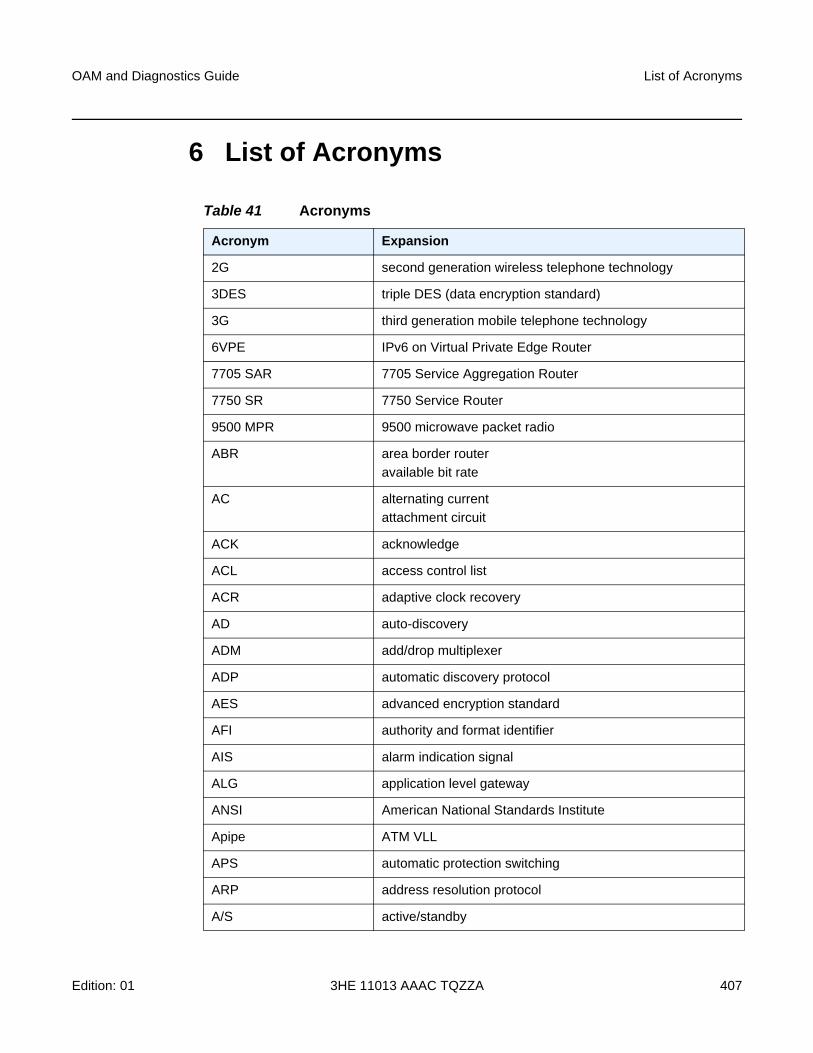
OAM and Diagnostics Guide List of Acronyms
Edition: 01 3HE 11013 AAAC TQZZA 407
6 List of Acronyms
Table 41 Acronyms
Acronym Expansion
2G second generation wireless telephone technology
3DES triple DES (data encryption standard)
3G third generation mobile telephone technology
6VPE IPv6 on Virtual Private Edge Router
7705 SAR 7705 Service Aggregation Router
7750 SR 7750 Service Router
9500 MPR 9500 microwave packet radio
ABR area border router
available bit rate
AC alternating current
attachment circuit
ACK acknowledge
ACL access control list
ACR adaptive clock recovery
AD auto-discovery
ADM add/drop multiplexer
ADP automatic discovery protocol
AES advanced encryption standard
AFI authority and format identifier
AIS alarm indication signal
ALG application level gateway
ANSI American National Standards Institute
Apipe ATM VLL
APS automatic protection switching
ARP address resolution protocol
A/S active/standby
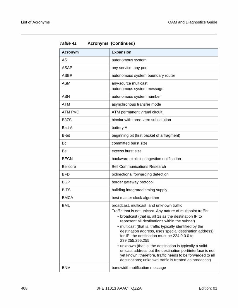
List of Acronyms
408
OAM and Diagnostics Guide
3HE 11013 AAAC TQZZA Edition: 01
AS autonomous system
ASAP any service, any port
ASBR autonomous system boundary router
ASM any-source multicast
autonomous system message
ASN autonomous system number
ATM asynchronous transfer mode
ATM PVC ATM permanent virtual circuit
B3ZS bipolar with three-zero substitution
Batt A battery A
B-bit beginning bit (first packet of a fragment)
Bc committed burst size
Be excess burst size
BECN backward explicit congestion notification
Bellcore Bell Communications Research
BFD bidirectional forwarding detection
BGP border gateway protocol
BITS building integrated timing supply
BMCA best master clock algorithm
BMU broadcast, multicast, and unknown traffic
Traffic that is not unicast. Any nature of multipoint traffic:
• broadcast (that is, all 1s as the destination IP to represent all destinations within the subnet)
• multicast (that is, traffic typically identified by the destination address, uses special destination address); for IP, the destination must be 224.0.0.0 to 239.255.255.255
• unknown (that is, the destination is typically a valid unicast address but the destination port/interface is not yet known; therefore, traffic needs to be forwarded to all destinations; unknown traffic is treated as broadcast)
BNM bandwidth notification message
Table 41 Acronyms (Continued)
Acronym Expansion
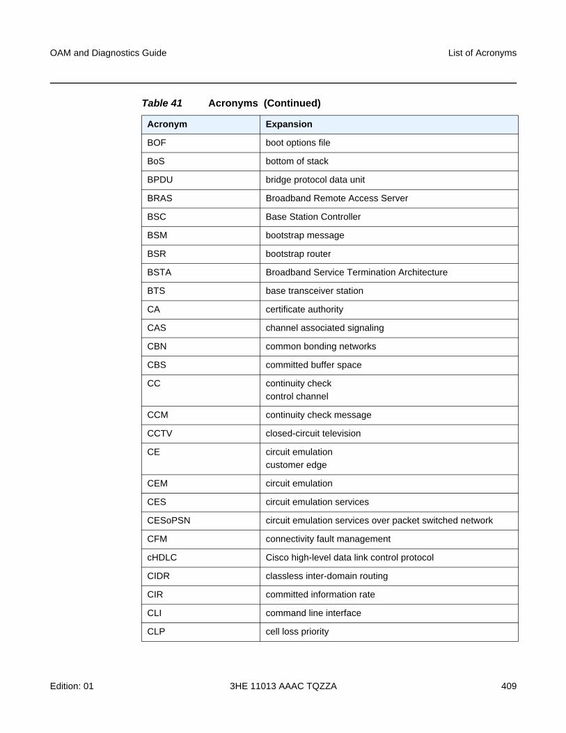
OAM and Diagnostics Guide List of Acronyms
Edition: 01 3HE 11013 AAAC TQZZA 409
BOF boot options file
BoS bottom of stack
BPDU bridge protocol data unit
BRAS Broadband Remote Access Server
BSC Base Station Controller
BSM bootstrap message
BSR bootstrap router
BSTA Broadband Service Termination Architecture
BTS base transceiver station
CA certificate authority
CAS channel associated signaling
CBN common bonding networks
CBS committed buffer space
CC continuity check
control channel
CCM continuity check message
CCTV closed-circuit television
CE circuit emulation
customer edge
CEM circuit emulation
CES circuit emulation services
CESoPSN circuit emulation services over packet switched network
CFM connectivity fault management
cHDLC Cisco high-level data link control protocol
CIDR classless inter-domain routing
CIR committed information rate
CLI command line interface
CLP cell loss priority
Table 41 Acronyms (Continued)
Acronym Expansion
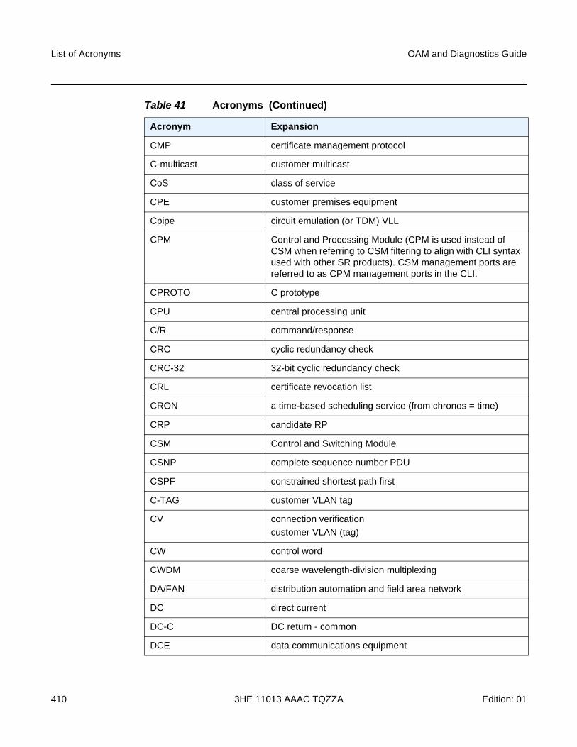
List of Acronyms
410
OAM and Diagnostics Guide
3HE 11013 AAAC TQZZA Edition: 01
CMP certificate management protocol
C-multicast customer multicast
CoS class of service
CPE customer premises equipment
Cpipe circuit emulation (or TDM) VLL
CPM Control and Processing Module (CPM is used instead of CSM when referring to CSM filtering to align with CLI syntax used with other SR products). CSM management ports are referred to as CPM management ports in the CLI.
CPROTO C prototype
CPU central processing unit
C/R command/response
CRC cyclic redundancy check
CRC-32 32-bit cyclic redundancy check
CRL certificate revocation list
CRON a time-based scheduling service (from chronos = time)
CRP candidate RP
CSM Control and Switching Module
CSNP complete sequence number PDU
CSPF constrained shortest path first
C-TAG customer VLAN tag
CV connection verification
customer VLAN (tag)
CW control word
CWDM coarse wavelength-division multiplexing
DA/FAN distribution automation and field area network
DC direct current
DC-C DC return - common
DCE data communications equipment
Table 41 Acronyms (Continued)
Acronym Expansion
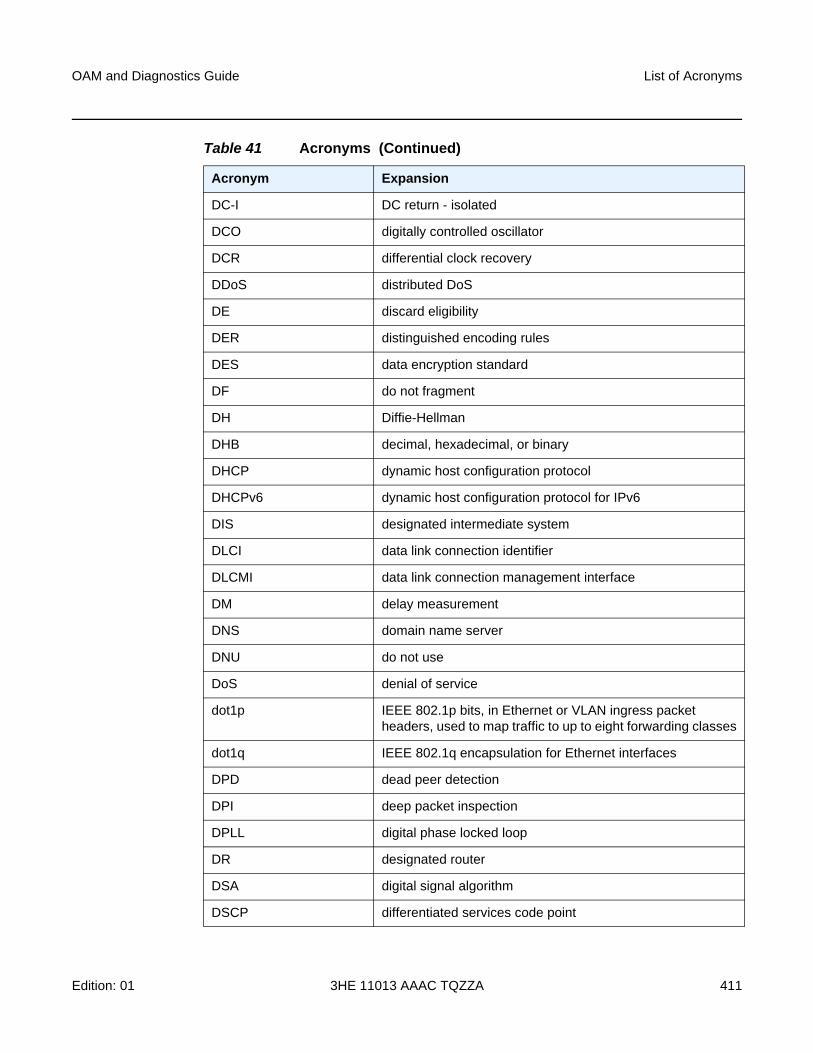
OAM and Diagnostics Guide List of Acronyms
Edition: 01 3HE 11013 AAAC TQZZA 411
DC-I DC return - isolated
DCO digitally controlled oscillator
DCR differential clock recovery
DDoS distributed DoS
DE discard eligibility
DER distinguished encoding rules
DES data encryption standard
DF do not fragment
DH Diffie-Hellman
DHB decimal, hexadecimal, or binary
DHCP dynamic host configuration protocol
DHCPv6 dynamic host configuration protocol for IPv6
DIS designated intermediate system
DLCI data link connection identifier
DLCMI data link connection management interface
DM delay measurement
DNS domain name server
DNU do not use
DoS denial of service
dot1p IEEE 802.1p bits, in Ethernet or VLAN ingress packet headers, used to map traffic to up to eight forwarding classes
dot1q IEEE 802.1q encapsulation for Ethernet interfaces
DPD dead peer detection
DPI deep packet inspection
DPLL digital phase locked loop
DR designated router
DSA digital signal algorithm
DSCP differentiated services code point
Table 41 Acronyms (Continued)
Acronym Expansion
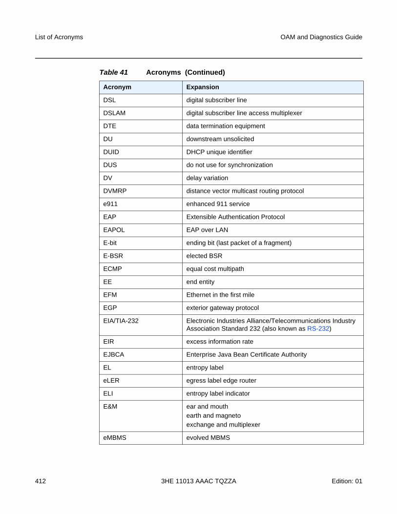
List of Acronyms
412
OAM and Diagnostics Guide
3HE 11013 AAAC TQZZA Edition: 01
DSL digital subscriber line
DSLAM digital subscriber line access multiplexer
DTE data termination equipment
DU downstream unsolicited
DUID DHCP unique identifier
DUS do not use for synchronization
DV delay variation
DVMRP distance vector multicast routing protocol
e911 enhanced 911 service
EAP Extensible Authentication Protocol
EAPOL EAP over LAN
E-bit ending bit (last packet of a fragment)
E-BSR elected BSR
ECMP equal cost multipath
EE end entity
EFM Ethernet in the first mile
EGP exterior gateway protocol
EIA/TIA-232 Electronic Industries Alliance/Telecommunications Industry Association Standard 232 (also known as RS-232)
EIR excess information rate
EJBCA Enterprise Java Bean Certificate Authority
EL entropy label
eLER egress label edge router
ELI entropy label indicator
E&M ear and mouth
earth and magneto
exchange and multiplexer
eMBMS evolved MBMS
Table 41 Acronyms (Continued)
Acronym Expansion
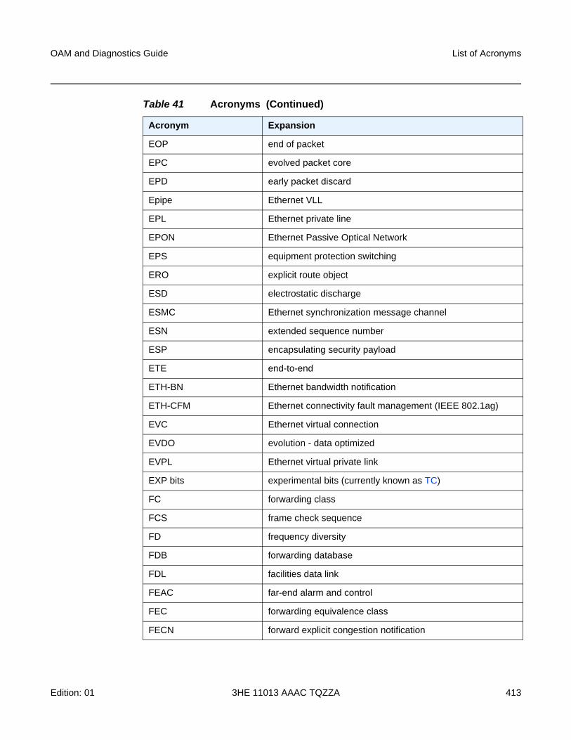
OAM and Diagnostics Guide List of Acronyms
Edition: 01 3HE 11013 AAAC TQZZA 413
EOP end of packet
EPC evolved packet core
EPD early packet discard
Epipe Ethernet VLL
EPL Ethernet private line
EPON Ethernet Passive Optical Network
EPS equipment protection switching
ERO explicit route object
ESD electrostatic discharge
ESMC Ethernet synchronization message channel
ESN extended sequence number
ESP encapsulating security payload
ETE end-to-end
ETH-BN Ethernet bandwidth notification
ETH-CFM Ethernet connectivity fault management (IEEE 802.1ag)
EVC Ethernet virtual connection
EVDO evolution - data optimized
EVPL Ethernet virtual private link
EXP bits experimental bits (currently known as TC)
FC forwarding class
FCS frame check sequence
FD frequency diversity
FDB forwarding database
FDL facilities data link
FEAC far-end alarm and control
FEC forwarding equivalence class
FECN forward explicit congestion notification
Table 41 Acronyms (Continued)
Acronym Expansion
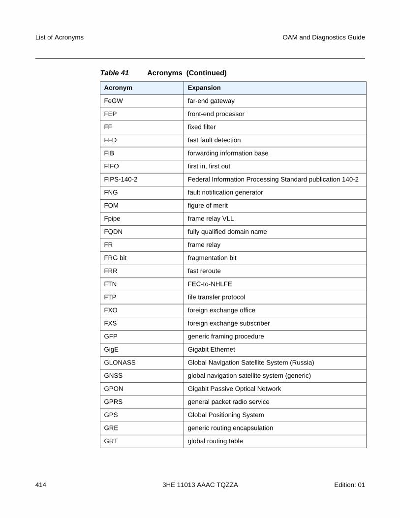
List of Acronyms
414
OAM and Diagnostics Guide
3HE 11013 AAAC TQZZA Edition: 01
FeGW far-end gateway
FEP front-end processor
FF fixed filter
FFD fast fault detection
FIB forwarding information base
FIFO first in, first out
FIPS-140-2 Federal Information Processing Standard publication 140-2
FNG fault notification generator
FOM figure of merit
Fpipe frame relay VLL
FQDN fully qualified domain name
FR frame relay
FRG bit fragmentation bit
FRR fast reroute
FTN FEC-to-NHLFE
FTP file transfer protocol
FXO foreign exchange office
FXS foreign exchange subscriber
GFP generic framing procedure
GigE Gigabit Ethernet
GLONASS Global Navigation Satellite System (Russia)
GNSS global navigation satellite system (generic)
GPON Gigabit Passive Optical Network
GPRS general packet radio service
GPS Global Positioning System
GRE generic routing encapsulation
GRT global routing table
Table 41 Acronyms (Continued)
Acronym Expansion
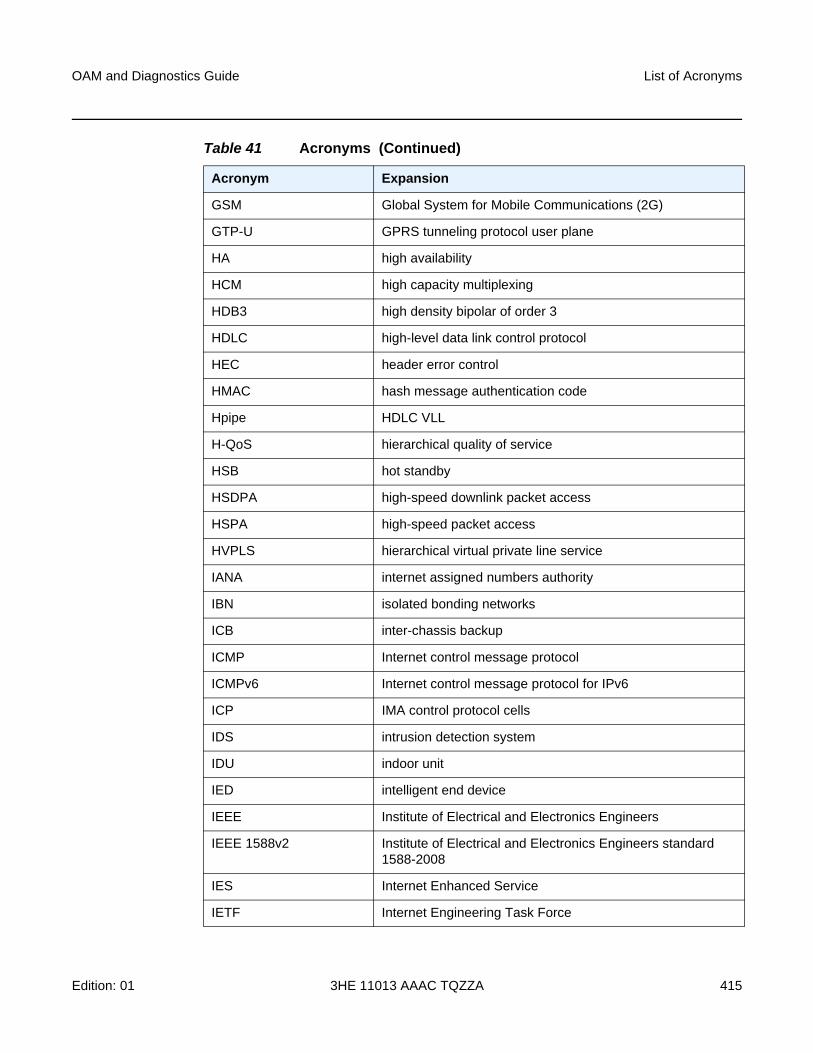
OAM and Diagnostics Guide List of Acronyms
Edition: 01 3HE 11013 AAAC TQZZA 415
GSM Global System for Mobile Communications (2G)
GTP-U GPRS tunneling protocol user plane
HA high availability
HCM high capacity multiplexing
HDB3 high density bipolar of order 3
HDLC high-level data link control protocol
HEC header error control
HMAC hash message authentication code
Hpipe HDLC VLL
H-QoS hierarchical quality of service
HSB hot standby
HSDPA high-speed downlink packet access
HSPA high-speed packet access
HVPLS hierarchical virtual private line service
IANA internet assigned numbers authority
IBN isolated bonding networks
ICB inter-chassis backup
ICMP Internet control message protocol
ICMPv6 Internet control message protocol for IPv6
ICP IMA control protocol cells
IDS intrusion detection system
IDU indoor unit
IED intelligent end device
IEEE Institute of Electrical and Electronics Engineers
IEEE 1588v2 Institute of Electrical and Electronics Engineers standard 1588-2008
IES Internet Enhanced Service
IETF Internet Engineering Task Force
Table 41 Acronyms (Continued)
Acronym Expansion
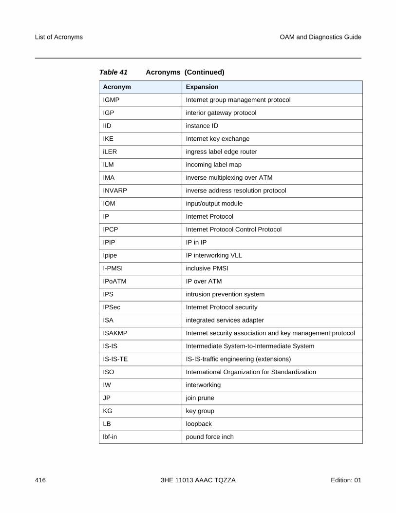
List of Acronyms
416
OAM and Diagnostics Guide
3HE 11013 AAAC TQZZA Edition: 01
IGMP Internet group management protocol
IGP interior gateway protocol
IID instance ID
IKE Internet key exchange
iLER ingress label edge router
ILM incoming label map
IMA inverse multiplexing over ATM
INVARP inverse address resolution protocol
IOM input/output module
IP Internet Protocol
IPCP Internet Protocol Control Protocol
IPIP IP in IP
Ipipe IP interworking VLL
I-PMSI inclusive PMSI
IPoATM IP over ATM
IPS intrusion prevention system
IPSec Internet Protocol security
ISA integrated services adapter
ISAKMP Internet security association and key management protocol
IS-IS Intermediate System-to-Intermediate System
IS-IS-TE IS-IS-traffic engineering (extensions)
ISO International Organization for Standardization
IW interworking
JP join prune
KG key group
LB loopback
lbf-in pound force inch
Table 41 Acronyms (Continued)
Acronym Expansion
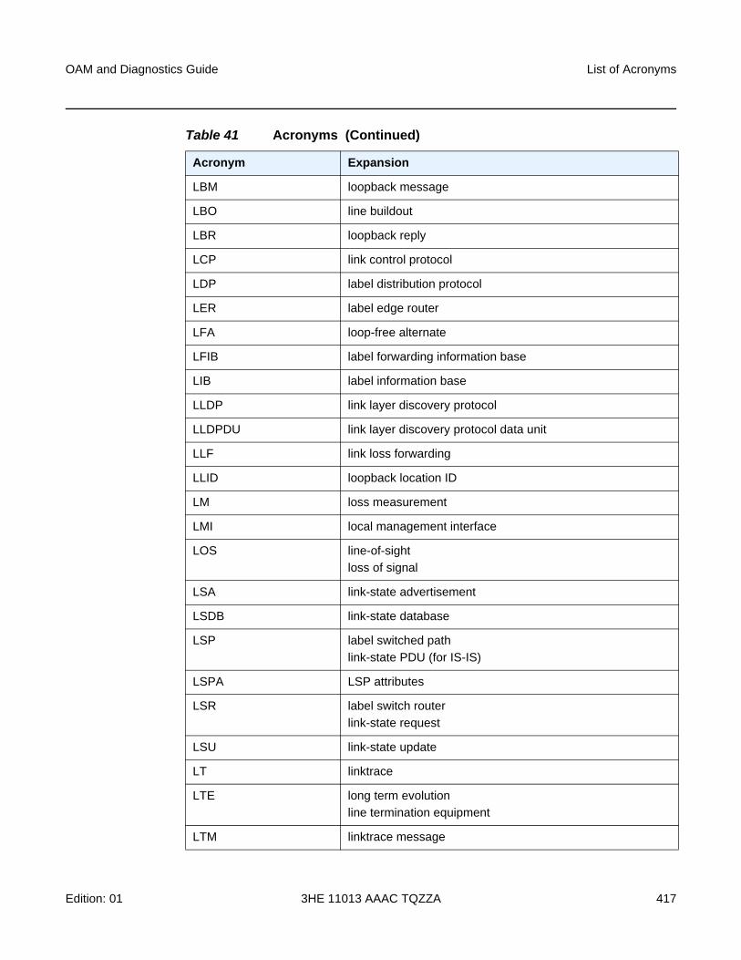
OAM and Diagnostics Guide List of Acronyms
Edition: 01 3HE 11013 AAAC TQZZA 417
LBM loopback message
LBO line buildout
LBR loopback reply
LCP link control protocol
LDP label distribution protocol
LER label edge router
LFA loop-free alternate
LFIB label forwarding information base
LIB label information base
LLDP link layer discovery protocol
LLDPDU link layer discovery protocol data unit
LLF link loss forwarding
LLID loopback location ID
LM loss measurement
LMI local management interface
LOS line-of-sight
loss of signal
LSA link-state advertisement
LSDB link-state database
LSP label switched path
link-state PDU (for IS-IS)
LSPA LSP attributes
LSR label switch router
link-state request
LSU link-state update
LT linktrace
LTE long term evolution
line termination equipment
LTM linktrace message
Table 41 Acronyms (Continued)
Acronym Expansion
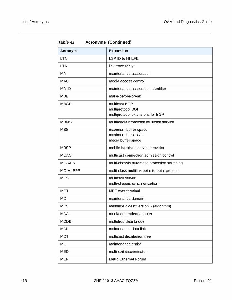
List of Acronyms
418
OAM and Diagnostics Guide
3HE 11013 AAAC TQZZA Edition: 01
LTN LSP ID to NHLFE
LTR link trace reply
MA maintenance association
MAC media access control
MA-ID maintenance association identifier
MBB make-before-break
MBGP multicast BGP
multiprotocol BGP
multiprotocol extensions for BGP
MBMS multimedia broadcast multicast service
MBS maximum buffer space
maximum burst size
media buffer space
MBSP mobile backhaul service provider
MCAC multicast connection admission control
MC-APS multi-chassis automatic protection switching
MC-MLPPP multi-class multilink point-to-point protocol
MCS multicast server
multi-chassis synchronization
MCT MPT craft terminal
MD maintenance domain
MD5 message digest version 5 (algorithm)
MDA media dependent adapter
MDDB multidrop data bridge
MDL maintenance data link
MDT multicast distribution tree
ME maintenance entity
MED multi-exit discriminator
MEF Metro Ethernet Forum
Table 41 Acronyms (Continued)
Acronym Expansion
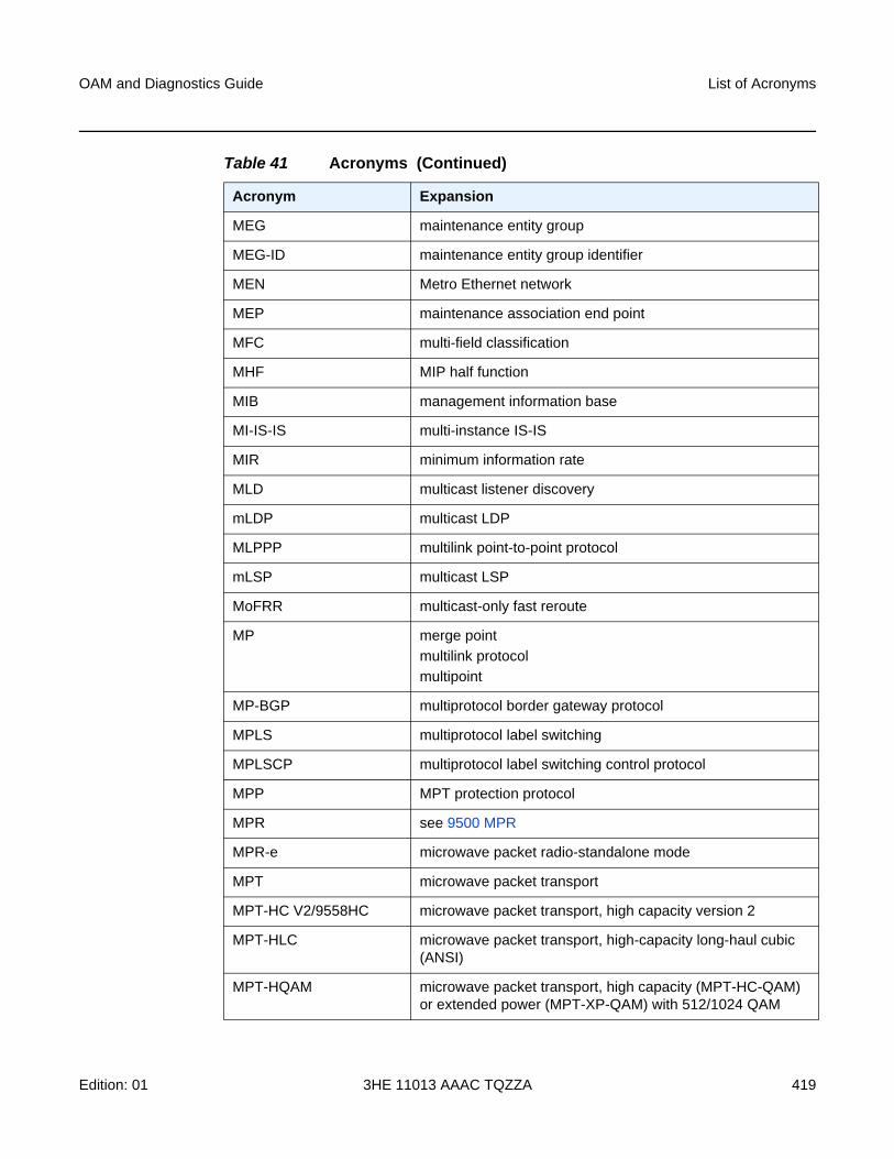
OAM and Diagnostics Guide List of Acronyms
Edition: 01 3HE 11013 AAAC TQZZA 419
MEG maintenance entity group
MEG-ID maintenance entity group identifier
MEN Metro Ethernet network
MEP maintenance association end point
MFC multi-field classification
MHF MIP half function
MIB management information base
MI-IS-IS multi-instance IS-IS
MIR minimum information rate
MLD multicast listener discovery
mLDP multicast LDP
MLPPP multilink point-to-point protocol
mLSP multicast LSP
MoFRR multicast-only fast reroute
MP merge point
multilink protocol
multipoint
MP-BGP multiprotocol border gateway protocol
MPLS multiprotocol label switching
MPLSCP multiprotocol label switching control protocol
MPP MPT protection protocol
MPR see 9500 MPR
MPR-e microwave packet radio-standalone mode
MPT microwave packet transport
MPT-HC V2/9558HC microwave packet transport, high capacity version 2
MPT-HLC microwave packet transport, high-capacity long-haul cubic (ANSI)
MPT-HQAM microwave packet transport, high capacity (MPT-HC-QAM) or extended power (MPT-XP-QAM) with 512/1024 QAM
Table 41 Acronyms (Continued)
Acronym Expansion
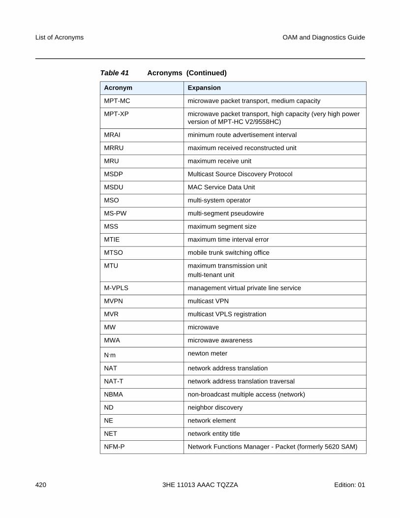
List of Acronyms
420
OAM and Diagnostics Guide
3HE 11013 AAAC TQZZA Edition: 01
MPT-MC microwave packet transport, medium capacity
MPT-XP microwave packet transport, high capacity (very high power version of MPT-HC V2/9558HC)
MRAI minimum route advertisement interval
MRRU maximum received reconstructed unit
MRU maximum receive unit
MSDP Multicast Source Discovery Protocol
MSDU MAC Service Data Unit
MSO multi-system operator
MS-PW multi-segment pseudowire
MSS maximum segment size
MTIE maximum time interval error
MTSO mobile trunk switching office
MTU maximum transmission unit
multi-tenant unit
M-VPLS management virtual private line service
MVPN multicast VPN
MVR multicast VPLS registration
MW microwave
MWA microwave awareness
N.m newton meter
NAT network address translation
NAT-T network address translation traversal
NBMA non-broadcast multiple access (network)
ND neighbor discovery
NE network element
NET network entity title
NFM-P Network Functions Manager - Packet (formerly 5620 SAM)
Table 41 Acronyms (Continued)
Acronym Expansion
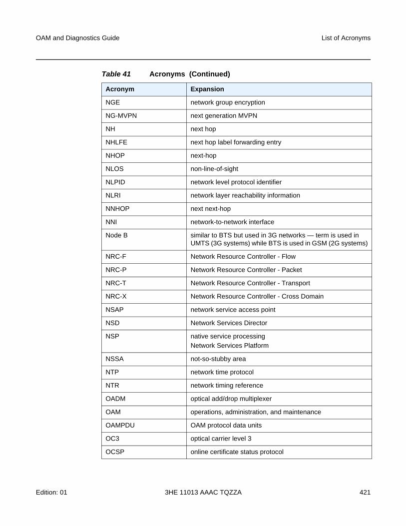
OAM and Diagnostics Guide List of Acronyms
Edition: 01 3HE 11013 AAAC TQZZA 421
NGE network group encryption
NG-MVPN next generation MVPN
NH next hop
NHLFE next hop label forwarding entry
NHOP next-hop
NLOS non-line-of-sight
NLPID network level protocol identifier
NLRI network layer reachability information
NNHOP next next-hop
NNI network-to-network interface
Node B similar to BTS but used in 3G networks — term is used in UMTS (3G systems) while BTS is used in GSM (2G systems)
NRC-F Network Resource Controller - Flow
NRC-P Network Resource Controller - Packet
NRC-T Network Resource Controller - Transport
NRC-X Network Resource Controller - Cross Domain
NSAP network service access point
NSD Network Services Director
NSP native service processing
Network Services Platform
NSSA not-so-stubby area
NTP network time protocol
NTR network timing reference
OADM optical add/drop multiplexer
OAM operations, administration, and maintenance
OAMPDU OAM protocol data units
OC3 optical carrier level 3
OCSP online certificate status protocol
Table 41 Acronyms (Continued)
Acronym Expansion
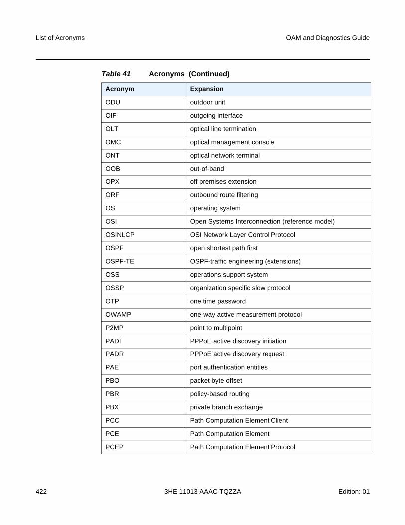
List of Acronyms
422
OAM and Diagnostics Guide
3HE 11013 AAAC TQZZA Edition: 01
ODU outdoor unit
OIF outgoing interface
OLT optical line termination
OMC optical management console
ONT optical network terminal
OOB out-of-band
OPX off premises extension
ORF outbound route filtering
OS operating system
OSI Open Systems Interconnection (reference model)
OSINLCP OSI Network Layer Control Protocol
OSPF open shortest path first
OSPF-TE OSPF-traffic engineering (extensions)
OSS operations support system
OSSP organization specific slow protocol
OTP one time password
OWAMP one-way active measurement protocol
P2MP point to multipoint
PADI PPPoE active discovery initiation
PADR PPPoE active discovery request
PAE port authentication entities
PBO packet byte offset
PBR policy-based routing
PBX private branch exchange
PCC Path Computation Element Client
PCE Path Computation Element
PCEP Path Computation Element Protocol
Table 41 Acronyms (Continued)
Acronym Expansion
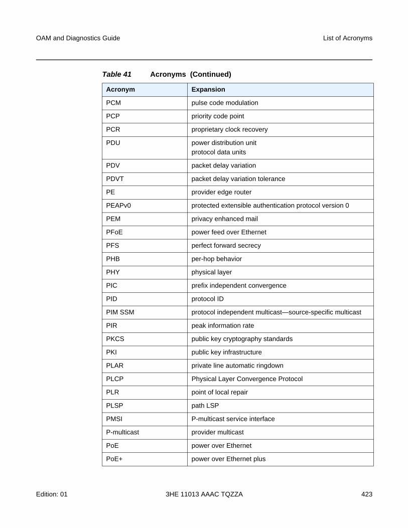
OAM and Diagnostics Guide List of Acronyms
Edition: 01 3HE 11013 AAAC TQZZA 423
PCM pulse code modulation
PCP priority code point
PCR proprietary clock recovery
PDU power distribution unit
protocol data units
PDV packet delay variation
PDVT packet delay variation tolerance
PE provider edge router
PEAPv0 protected extensible authentication protocol version 0
PEM privacy enhanced mail
PFoE power feed over Ethernet
PFS perfect forward secrecy
PHB per-hop behavior
PHY physical layer
PIC prefix independent convergence
PID protocol ID
PIM SSM protocol independent multicast—source-specific multicast
PIR peak information rate
PKCS public key cryptography standards
PKI public key infrastructure
PLAR private line automatic ringdown
PLCP Physical Layer Convergence Protocol
PLR point of local repair
PLSP path LSP
PMSI P-multicast service interface
P-multicast provider multicast
PoE power over Ethernet
PoE+ power over Ethernet plus
Table 41 Acronyms (Continued)
Acronym Expansion
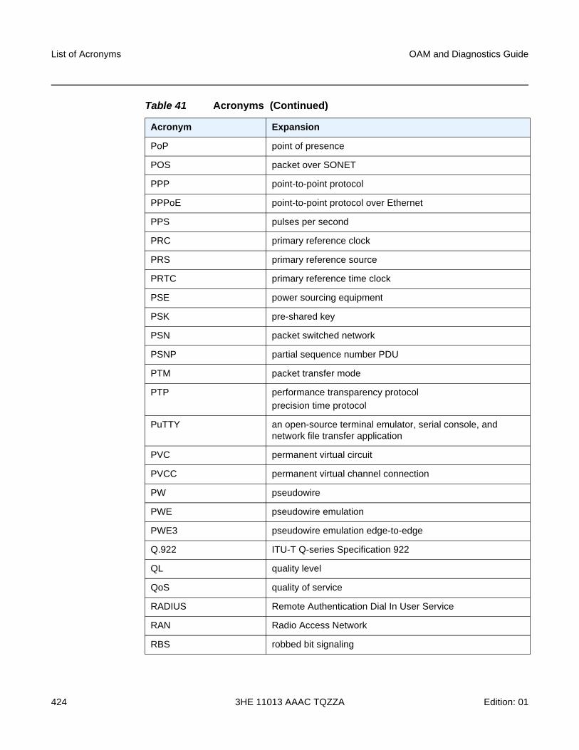
List of Acronyms
424
OAM and Diagnostics Guide
3HE 11013 AAAC TQZZA Edition: 01
PoP point of presence
POS packet over SONET
PPP point-to-point protocol
PPPoE point-to-point protocol over Ethernet
PPS pulses per second
PRC primary reference clock
PRS primary reference source
PRTC primary reference time clock
PSE power sourcing equipment
PSK pre-shared key
PSN packet switched network
PSNP partial sequence number PDU
PTM packet transfer mode
PTP performance transparency protocol
precision time protocol
PuTTY an open-source terminal emulator, serial console, and network file transfer application
PVC permanent virtual circuit
PVCC permanent virtual channel connection
PW pseudowire
PWE pseudowire emulation
PWE3 pseudowire emulation edge-to-edge
Q.922 ITU-T Q-series Specification 922
QL quality level
QoS quality of service
RADIUS Remote Authentication Dial In User Service
RAN Radio Access Network
RBS robbed bit signaling
Table 41 Acronyms (Continued)
Acronym Expansion
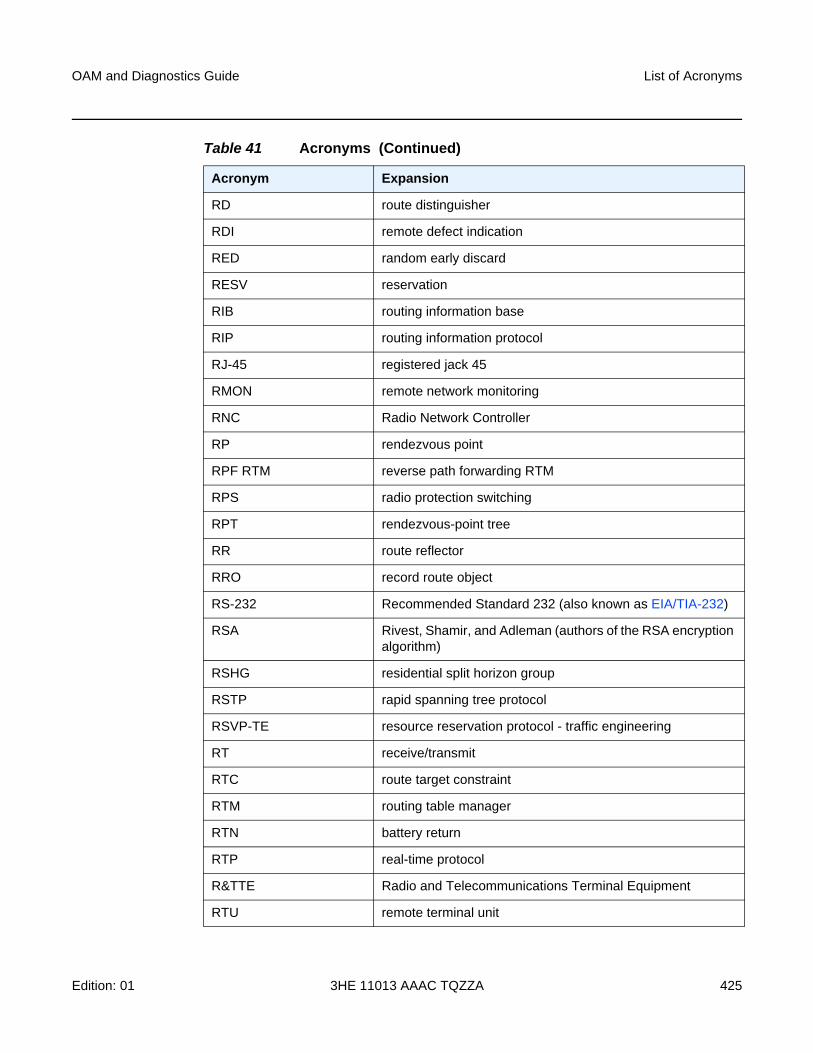
OAM and Diagnostics Guide List of Acronyms
Edition: 01 3HE 11013 AAAC TQZZA 425
RD route distinguisher
RDI remote defect indication
RED random early discard
RESV reservation
RIB routing information base
RIP routing information protocol
RJ-45 registered jack 45
RMON remote network monitoring
RNC Radio Network Controller
RP rendezvous point
RPF RTM reverse path forwarding RTM
RPS radio protection switching
RPT rendezvous-point tree
RR route reflector
RRO record route object
RS-232 Recommended Standard 232 (also known as EIA/TIA-232)
RSA Rivest, Shamir, and Adleman (authors of the RSA encryption algorithm)
RSHG residential split horizon group
RSTP rapid spanning tree protocol
RSVP-TE resource reservation protocol - traffic engineering
RT receive/transmit
RTC route target constraint
RTM routing table manager
RTN battery return
RTP real-time protocol
R&TTE Radio and Telecommunications Terminal Equipment
RTU remote terminal unit
Table 41 Acronyms (Continued)
Acronym Expansion
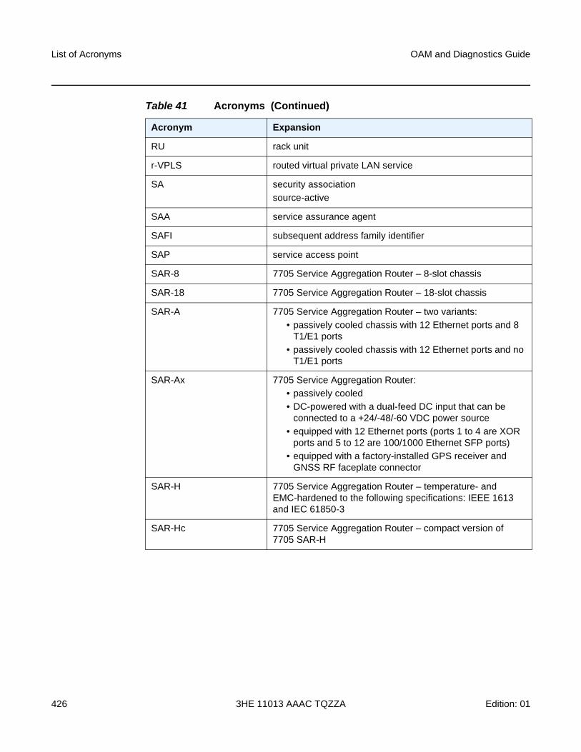
List of Acronyms
426
OAM and Diagnostics Guide
3HE 11013 AAAC TQZZA Edition: 01
RU rack unit
r-VPLS routed virtual private LAN service
SA security association
source-active
SAA service assurance agent
SAFI subsequent address family identifier
SAP service access point
SAR-8 7705 Service Aggregation Router – 8-slot chassis
SAR-18 7705 Service Aggregation Router – 18-slot chassis
SAR-A 7705 Service Aggregation Router – two variants:
• passively cooled chassis with 12 Ethernet ports and 8 T1/E1 ports
• passively cooled chassis with 12 Ethernet ports and no T1/E1 ports
SAR-Ax 7705 Service Aggregation Router:
• passively cooled
• DC-powered with a dual-feed DC input that can be connected to a +24/-48/-60 VDC power source
• equipped with 12 Ethernet ports (ports 1 to 4 are XOR ports and 5 to 12 are 100/1000 Ethernet SFP ports)
• equipped with a factory-installed GPS receiver and GNSS RF faceplate connector
SAR-H 7705 Service Aggregation Router – temperature- and EMC-hardened to the following specifications: IEEE 1613 and IEC 61850-3
SAR-Hc 7705 Service Aggregation Router – compact version of 7705 SAR-H
Table 41 Acronyms (Continued)
Acronym Expansion
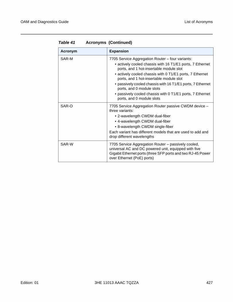
OAM and Diagnostics Guide List of Acronyms
Edition: 01 3HE 11013 AAAC TQZZA 427
SAR-M 7705 Service Aggregation Router – four variants:
• actively cooled chassis with 16 T1/E1 ports, 7 Ethernet ports, and 1 hot-insertable module slot
• actively cooled chassis with 0 T1/E1 ports, 7 Ethernet ports, and 1 hot-insertable module slot
• passively cooled chassis with 16 T1/E1 ports, 7 Ethernet ports, and 0 module slots
• passively cooled chassis with 0 T1/E1 ports, 7 Ethernet ports, and 0 module slots
SAR-O 7705 Service Aggregation Router passive CWDM device – three variants:
• 2-wavelength CWDM dual-fiber
• 4-wavelength CWDM dual-fiber
• 8-wavelength CWDM single-fiber
Each variant has different models that are used to add and drop different wavelengths
SAR-W 7705 Service Aggregation Router – passively cooled, universal AC and DC powered unit, equipped with five Gigabit Ethernet ports (three SFP ports and two RJ-45 Power over Ethernet (PoE) ports)
Table 41 Acronyms (Continued)
Acronym Expansion
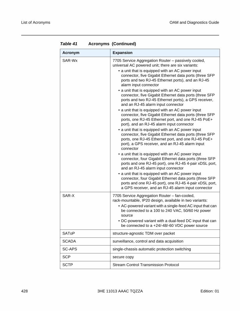
List of Acronyms
428
OAM and Diagnostics Guide
3HE 11013 AAAC TQZZA Edition: 01
SAR-Wx 7705 Service Aggregation Router – passively cooled, universal AC powered unit; there are six variants:
• a unit that is equipped with an AC power input connector, five Gigabit Ethernet data ports (three SFP ports and two RJ-45 Ethernet ports), and an RJ-45 alarm input connector
• a unit that is equipped with an AC power input connector, five Gigabit Ethernet data ports (three SFP ports and two RJ-45 Ethernet ports), a GPS receiver, and an RJ-45 alarm input connector
• a unit that is equipped with an AC power input connector, five Gigabit Ethernet data ports (three SFP ports, one RJ-45 Ethernet port, and one RJ-45 PoE+ port), and an RJ-45 alarm input connector
• a unit that is equipped with an AC power input connector, five Gigabit Ethernet data ports (three SFP ports, one RJ-45 Ethernet port, and one RJ-45 PoE+ port), a GPS receiver, and an RJ-45 alarm input connector
• a unit that is equipped with an AC power input connector, four Gigabit Ethernet data ports (three SFP ports and one RJ-45 port), one RJ-45 4-pair xDSL port, and an RJ-45 alarm input connector
• a unit that is equipped with an AC power input connector, four Gigabit Ethernet data ports (three SFP ports and one RJ-45 port), one RJ-45 4-pair xDSL port, a GPS receiver, and an RJ-45 alarm input connector
SAR-X 7705 Service Aggregation Router – fan-cooled, rack-mountable, IP20 design, available in two variants:
• AC-powered variant with a single-feed AC input that can be connected to a 100 to 240 VAC, 50/60 Hz power source
• DC-powered variant with a dual-feed DC input that can be connected to a +24/-48/-60 VDC power source
SAToP structure-agnostic TDM over packet
SCADA surveillance, control and data acquisition
SC-APS single-chassis automatic protection switching
SCP secure copy
SCTP Stream Control Transmission Protocol
Table 41 Acronyms (Continued)
Acronym Expansion
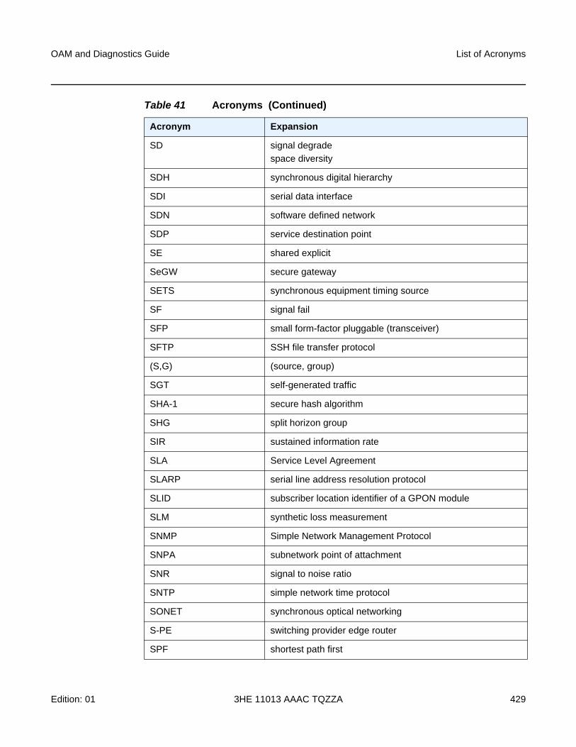
OAM and Diagnostics Guide List of Acronyms
Edition: 01 3HE 11013 AAAC TQZZA 429
SD signal degrade
space diversity
SDH synchronous digital hierarchy
SDI serial data interface
SDN software defined network
SDP service destination point
SE shared explicit
SeGW secure gateway
SETS synchronous equipment timing source
SF signal fail
SFP small form-factor pluggable (transceiver)
SFTP SSH file transfer protocol
(S,G) (source, group)
SGT self-generated traffic
SHA-1 secure hash algorithm
SHG split horizon group
SIR sustained information rate
SLA Service Level Agreement
SLARP serial line address resolution protocol
SLID subscriber location identifier of a GPON module
SLM synthetic loss measurement
SNMP Simple Network Management Protocol
SNPA subnetwork point of attachment
SNR signal to noise ratio
SNTP simple network time protocol
SONET synchronous optical networking
S-PE switching provider edge router
SPF shortest path first
Table 41 Acronyms (Continued)
Acronym Expansion
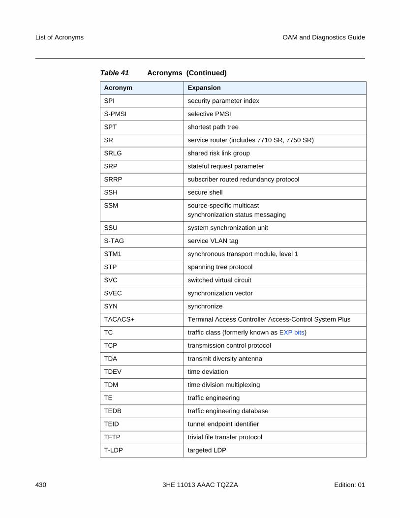
List of Acronyms
430
OAM and Diagnostics Guide
3HE 11013 AAAC TQZZA Edition: 01
SPI security parameter index
S-PMSI selective PMSI
SPT shortest path tree
SR service router (includes 7710 SR, 7750 SR)
SRLG shared risk link group
SRP stateful request parameter
SRRP subscriber routed redundancy protocol
SSH secure shell
SSM source-specific multicast
synchronization status messaging
SSU system synchronization unit
S-TAG service VLAN tag
STM1 synchronous transport module, level 1
STP spanning tree protocol
SVC switched virtual circuit
SVEC synchronization vector
SYN synchronize
TACACS+ Terminal Access Controller Access-Control System Plus
TC traffic class (formerly known as EXP bits)
TCP transmission control protocol
TDA transmit diversity antenna
TDEV time deviation
TDM time division multiplexing
TE traffic engineering
TEDB traffic engineering database
TEID tunnel endpoint identifier
TFTP trivial file transfer protocol
T-LDP targeted LDP
Table 41 Acronyms (Continued)
Acronym Expansion
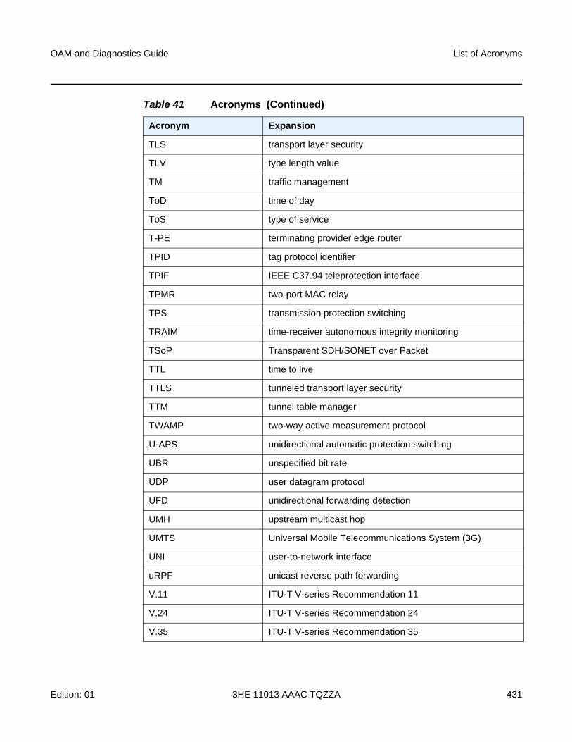
OAM and Diagnostics Guide List of Acronyms
Edition: 01 3HE 11013 AAAC TQZZA 431
TLS transport layer security
TLV type length value
TM traffic management
ToD time of day
ToS type of service
T-PE terminating provider edge router
TPID tag protocol identifier
TPIF IEEE C37.94 teleprotection interface
TPMR two-port MAC relay
TPS transmission protection switching
TRAIM time-receiver autonomous integrity monitoring
TSoP Transparent SDH/SONET over Packet
TTL time to live
TTLS tunneled transport layer security
TTM tunnel table manager
TWAMP two-way active measurement protocol
U-APS unidirectional automatic protection switching
UBR unspecified bit rate
UDP user datagram protocol
UFD unidirectional forwarding detection
UMH upstream multicast hop
UMTS Universal Mobile Telecommunications System (3G)
UNI user-to-network interface
uRPF unicast reverse path forwarding
V.11 ITU-T V-series Recommendation 11
V.24 ITU-T V-series Recommendation 24
V.35 ITU-T V-series Recommendation 35
Table 41 Acronyms (Continued)
Acronym Expansion
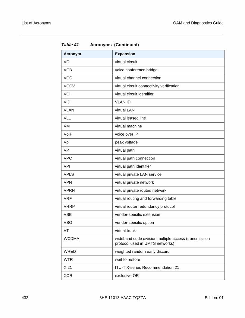
List of Acronyms
432
OAM and Diagnostics Guide
3HE 11013 AAAC TQZZA Edition: 01
VC virtual circuit
VCB voice conference bridge
VCC virtual channel connection
VCCV virtual circuit connectivity verification
VCI virtual circuit identifier
VID VLAN ID
VLAN virtual LAN
VLL virtual leased line
VM virtual machine
VoIP voice over IP
Vp peak voltage
VP virtual path
VPC virtual path connection
VPI virtual path identifier
VPLS virtual private LAN service
VPN virtual private network
VPRN virtual private routed network
VRF virtual routing and forwarding table
VRRP virtual router redundancy protocol
VSE vendor-specific extension
VSO vendor-specific option
VT virtual trunk
WCDMA wideband code division multiple access (transmission protocol used in UMTS networks)
WRED weighted random early discard
WTR wait to restore
X.21 ITU-T X-series Recommendation 21
XOR exclusive-OR
Table 41 Acronyms (Continued)
Acronym Expansion

OAM and Diagnostics Guide List of Acronyms
Edition: 01 3HE 11013 AAAC TQZZA 433
XRO exclude route object
Table 41 Acronyms (Continued)
Acronym Expansion

List of Acronyms
434
OAM and Diagnostics Guide
3HE 11013 AAAC TQZZA Edition: 01
OAM and Diagnostics Guide Standards and Protocol Support
Edition: 01 3HE 11013 AAAC TQZZA 435
7 Standards and Protocol Support
This chapter lists the 7705 SAR compliance with EMC, environmental, and safety standards, telecom standards, and supported protocols:
• EMC Industrial Standards Compliance
• EMC Regulatory and Customer Standards Compliance
• Environmental Standards Compliance
• Safety Standards Compliance
• Telecom Interface Compliance
• Directives, Regional Approvals and Certifications Compliance
• Security Standards
• Telecom Standards
• Protocol Support
• Proprietary MIBs
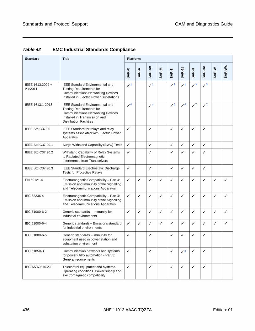
Standards and Protocol Support
436
OAM and Diagnostics Guide
3HE 11013 AAAC TQZZA Edition: 01
Table 42 EMC Industrial Standards Compliance
Standard Title Platform
SA
R-X
SA
R-A
SA
R-A
x
SA
R-M
SA
R-8
SA
R-1
8
SA
R-H
SA
R-H
c
SA
R-W
SA
R-W
x
IEEE 1613:2009 + A1:2011
IEEE Standard Environmental and Testing Requirements for Communications Networking Devices Installed in Electric Power Substations
✓ 1 ✓ 1 ✓ 2 ✓ 1 ✓ 3 ✓ 3
IEEE 1613.1-2013 IEEE Standard Environmental and Testing Requirements for Communications Networking Devices Installed in Transmission and Distribution Facilities
✓ 4 ✓ 4 ✓ 5 ✓ 6 ✓ 7 ✓ 7
IEEE Std C37.90 IEEE Standard for relays and relay systems associated with Electric Power Apparatus
✓ ✓ ✓ ✓ ✓ ✓
IEEE Std C37.90.1 Surge Withstand Capability (SWC) Tests ✓ ✓ ✓ ✓ ✓ ✓
IEEE Std C37.90.2 Withstand Capability of Relay Systems to Radiated Electromagnetic Interference from Transceivers
✓ ✓ ✓ ✓ ✓ ✓
IEEE Std C37.90.3 IEEE Standard Electrostatic Discharge Tests for Protective Relays
✓ ✓ ✓ ✓ ✓ ✓
EN 50121-4 Electromagnetic Compatibility – Part 4: Emission and Immunity of the Signalling and Telecommunications Apparatus
✓ ✓ ✓ ✓ ✓ ✓ ✓ ✓ ✓ ✓
IEC 62236-4 Electromagnetic Compatibility – Part 4: Emission and Immunity of the Signalling and Telecommunications Apparatus
✓ ✓ ✓ ✓ ✓ ✓ ✓ ✓ ✓ ✓
IEC 61000-6-2 Generic standards – Immunity for industrial environments
✓ ✓ ✓ ✓ ✓ ✓ ✓ ✓ ✓ ✓
IEC 61000-6-4 Generic standards – Emissions standard for industrial environments
✓ ✓ ✓ ✓ ✓ ✓ ✓ ✓ ✓ ✓
IEC 61000-6-5 Generic standards – immunity for equipment used in power station and substation environment
✓ ✓ ✓ ✓ ✓ ✓
IEC 61850-3 Communication networks and systems for power utility automation - Part 3: General requirements
✓ ✓ ✓ ✓ 8 ✓ ✓
IEC/AS 60870.2.1 Telecontrol equipment and systems. Operating conditions. Power supply and electromagnetic compatibility
✓ ✓ ✓ ✓ ✓ ✓
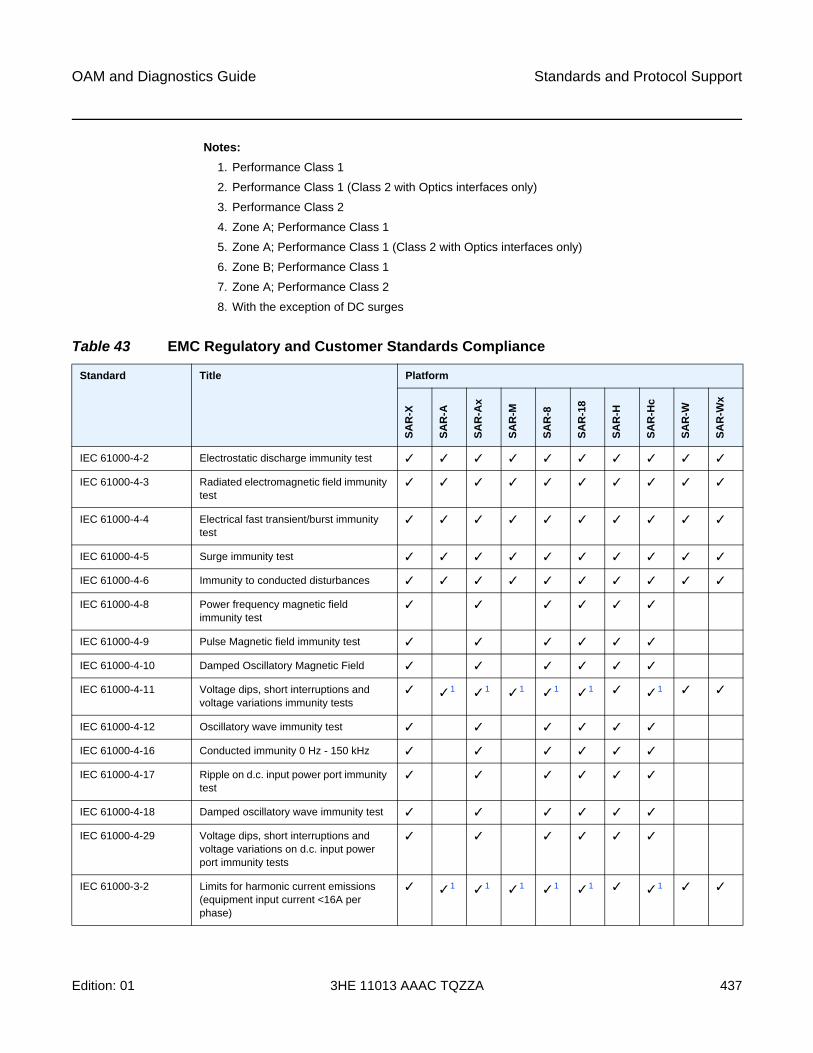
OAM and Diagnostics Guide Standards and Protocol Support
Edition: 01 3HE 11013 AAAC TQZZA 437
Notes:
1. Performance Class 1
2. Performance Class 1 (Class 2 with Optics interfaces only)
3. Performance Class 2
4. Zone A; Performance Class 1
5. Zone A; Performance Class 1 (Class 2 with Optics interfaces only)
6. Zone B; Performance Class 1
7. Zone A; Performance Class 2
8. With the exception of DC surges
Table 43 EMC Regulatory and Customer Standards Compliance
Standard Title Platform
SA
R-X
SA
R-A
SA
R-A
x
SA
R-M
SA
R-8
SA
R-1
8
SA
R-H
SA
R-H
c
SA
R-W
SA
R-W
x
IEC 61000-4-2 Electrostatic discharge immunity test ✓ ✓ ✓ ✓ ✓ ✓ ✓ ✓ ✓ ✓
IEC 61000-4-3 Radiated electromagnetic field immunity test
✓ ✓ ✓ ✓ ✓ ✓ ✓ ✓ ✓ ✓
IEC 61000-4-4 Electrical fast transient/burst immunity test
✓ ✓ ✓ ✓ ✓ ✓ ✓ ✓ ✓ ✓
IEC 61000-4-5 Surge immunity test ✓ ✓ ✓ ✓ ✓ ✓ ✓ ✓ ✓ ✓
IEC 61000-4-6 Immunity to conducted disturbances ✓ ✓ ✓ ✓ ✓ ✓ ✓ ✓ ✓ ✓
IEC 61000-4-8 Power frequency magnetic field immunity test
✓ ✓ ✓ ✓ ✓ ✓
IEC 61000-4-9 Pulse Magnetic field immunity test ✓ ✓ ✓ ✓ ✓ ✓
IEC 61000-4-10 Damped Oscillatory Magnetic Field ✓ ✓ ✓ ✓ ✓ ✓
IEC 61000-4-11 Voltage dips, short interruptions and voltage variations immunity tests
✓ ✓ 1 ✓ 1 ✓ 1 ✓ 1 ✓ 1 ✓ ✓ 1 ✓ ✓
IEC 61000-4-12 Oscillatory wave immunity test ✓ ✓ ✓ ✓ ✓ ✓
IEC 61000-4-16 Conducted immunity 0 Hz - 150 kHz ✓ ✓ ✓ ✓ ✓ ✓
IEC 61000-4-17 Ripple on d.c. input power port immunity test
✓ ✓ ✓ ✓ ✓ ✓
IEC 61000-4-18 Damped oscillatory wave immunity test ✓ ✓ ✓ ✓ ✓ ✓
IEC 61000-4-29 Voltage dips, short interruptions and voltage variations on d.c. input power port immunity tests
✓ ✓ ✓ ✓ ✓ ✓
IEC 61000-3-2 Limits for harmonic current emissions (equipment input current <16A per phase)
✓ ✓ 1 ✓ 1 ✓ 1 ✓ 1 ✓ 1 ✓ ✓ 1 ✓ ✓
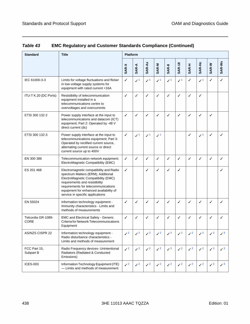
Standards and Protocol Support
438
OAM and Diagnostics Guide
3HE 11013 AAAC TQZZA Edition: 01
IEC 61000-3-3 Limits for voltage fluctuations and flicker in low-voltage supply systems for equipment with rated current <16A
✓ ✓ 1 ✓ 1 ✓ 1 ✓ 1 ✓ 1 ✓ ✓ 1 ✓ ✓
ITU-T K.20 (DC Ports) Resistibility of telecommunication equipment installed in a telecommunications centre to overvoltages and overcurrents
✓ ✓ ✓ ✓ ✓ ✓ ✓ ✓
ETSI 300 132-2 Power supply interface at the input to telecommunications and datacom (ICT) equipment; Part 2: Operated by -48 V direct current (dc)
✓ ✓ ✓ ✓ ✓ ✓ ✓ ✓ ✓
ETSI 300 132-3 Power supply interface at the input to telecommunications equipment; Part 3: Operated by rectified current source, alternating current source or direct current source up to 400V
✓ ✓ 1 ✓ 1 ✓ 1 ✓ ✓ 1 ✓ ✓
EN 300 386 Telecommunication network equipment; ElectroMagnetic Compatibility (EMC)
✓ ✓ ✓ ✓ ✓ ✓ ✓ ✓ ✓ ✓
ES 201 468 Electromagnetic compatibility and Radio spectrum Matters (ERM); Additional ElectroMagnetic Compatibility (EMC) requirements and resistibility requirements for telecommunications equipment for enhanced availability of service in specific applications
✓ ✓ ✓ ✓ ✓ ✓
EN 55024 Information technology equipment -Immunity characteristics - Limits and methods of measurements
✓ ✓ ✓ ✓ ✓ ✓ ✓ ✓ ✓ ✓
Telcordia GR-1089-CORE
EMC and Electrical Safety - Generic Criteria for Network Telecommunications Equipment
✓ ✓ ✓ ✓ ✓ ✓ ✓ ✓ ✓ ✓
AS/NZS CISPR 22 Information technology equipment - Radio disturbance characteristics - Limits and methods of measurement
✓ 2 ✓ 2 ✓ 2 ✓ 2 ✓ 2 ✓ 2 ✓ 2 ✓ 2 ✓ 3 ✓ 3
FCC Part 15, Subpart B
Radio Frequency devices- Unintentional Radiators (Radiated & Conducted Emissions)
✓ 2 ✓ 2 ✓ 2 ✓ 2 ✓ 2 ✓ 2 ✓ 2 ✓ 2 ✓ 3 ✓ 3
ICES-003 Information Technology Equipment (ITE) — Limits and methods of measurement
✓ 2 ✓ 2 ✓ 2 ✓ 2 ✓ 2 ✓ 2 ✓ 2 ✓ 2 ✓ 3 ✓ 3
Table 43 EMC Regulatory and Customer Standards Compliance (Continued)
Standard Title Platform
SA
R-X
SA
R-A
SA
R-A
x
SA
R-M
SA
R-8
SA
R-1
8
SA
R-H
SA
R-H
c
SA
R-W
SA
R-W
x
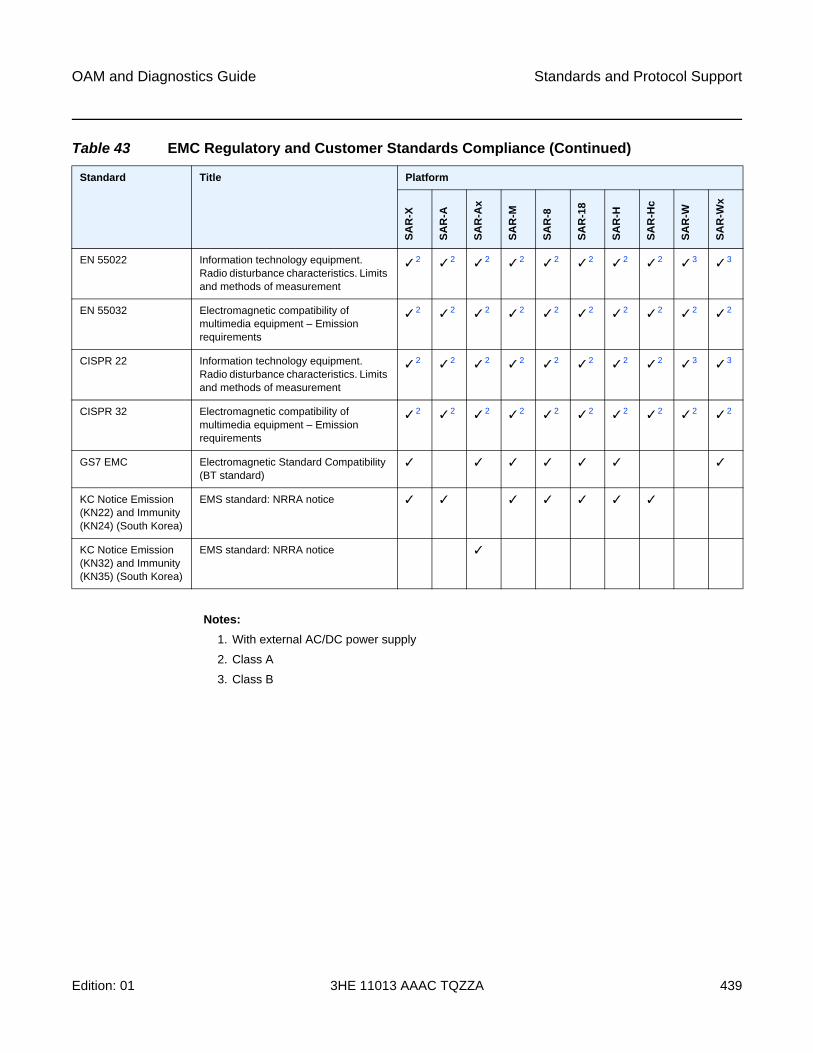
OAM and Diagnostics Guide Standards and Protocol Support
Edition: 01 3HE 11013 AAAC TQZZA 439
Notes:
1. With external AC/DC power supply
2. Class A
3. Class B
EN 55022 Information technology equipment. Radio disturbance characteristics. Limits and methods of measurement
✓ 2 ✓ 2 ✓ 2 ✓ 2 ✓ 2 ✓ 2 ✓ 2 ✓ 2 ✓ 3 ✓ 3
EN 55032 Electromagnetic compatibility of multimedia equipment – Emission requirements
✓ 2 ✓ 2 ✓ 2 ✓ 2 ✓ 2 ✓ 2 ✓ 2 ✓ 2 ✓ 2 ✓ 2
CISPR 22 Information technology equipment. Radio disturbance characteristics. Limits and methods of measurement
✓ 2 ✓ 2 ✓ 2 ✓ 2 ✓ 2 ✓ 2 ✓ 2 ✓ 2 ✓ 3 ✓ 3
CISPR 32 Electromagnetic compatibility of multimedia equipment – Emission requirements
✓ 2 ✓ 2 ✓ 2 ✓ 2 ✓ 2 ✓ 2 ✓ 2 ✓ 2 ✓ 2 ✓ 2
GS7 EMC Electromagnetic Standard Compatibility (BT standard)
✓ ✓ ✓ ✓ ✓ ✓ ✓
KC Notice Emission (KN22) and Immunity (KN24) (South Korea)
EMS standard: NRRA notice ✓ ✓ ✓ ✓ ✓ ✓ ✓
KC Notice Emission (KN32) and Immunity (KN35) (South Korea)
EMS standard: NRRA notice ✓
Table 43 EMC Regulatory and Customer Standards Compliance (Continued)
Standard Title Platform
SA
R-X
SA
R-A
SA
R-A
x
SA
R-M
SA
R-8
SA
R-1
8
SA
R-H
SA
R-H
c
SA
R-W
SA
R-W
x
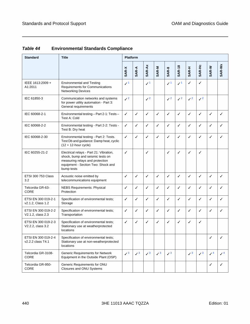
Standards and Protocol Support
440
OAM and Diagnostics Guide
3HE 11013 AAAC TQZZA Edition: 01
Table 44 Environmental Standards Compliance
Standard Title Platform
SA
R-X
SA
R-A
SA
R-A
x
SA
R-M
SA
R-8
SA
R-1
8
SA
R-H
SA
R-H
c
SA
R-W
SA
R-W
x
IEEE 1613:2009 + A1:2011
Environmental and Testing Requirements for Communications Networking Devices
✓ 1 ✓ 1 ✓ 1 ✓ 1 ✓ ✓
IEC 61850-3 Communication networks and systems for power utility automation - Part 3: General requirements
✓ 2 ✓ 2 ✓ 2 ✓ 2 ✓ 2 ✓ 2
IEC 60068-2-1 Environmental testing – Part 2-1: Tests – Test A: Cold
✓ ✓ ✓ ✓ ✓ ✓ ✓ ✓ ✓ ✓
IEC 60068-2-2 Environmental testing - Part 2-2: Tests - Test B: Dry heat
✓ ✓ ✓ ✓ ✓ ✓ ✓ ✓ ✓ ✓
IEC 60068-2-30 Environmental testing - Part 2: Tests. Test Db and guidance: Damp heat, cyclic (12 + 12-hour cycle)
✓ ✓ ✓ ✓ ✓ ✓ ✓ ✓ ✓ ✓
IEC 60255-21-2 Electrical relays - Part 21: Vibration, shock, bump and seismic tests on measuring relays and protection equipment - Section Two: Shock and bump tests
✓ ✓ ✓ ✓ ✓ ✓
ETSI 300 753 Class 3.2
Acoustic noise emitted by telecommunications equipment
✓ ✓ ✓ ✓ ✓ ✓ ✓ ✓ ✓ ✓
Telcordia GR-63-CORE
NEBS Requirements: Physical Protection
✓ ✓ ✓ ✓ ✓ ✓ ✓ ✓ ✓ ✓
ETSI EN 300 019-2-1 v2.1.2, Class 1.2
Specification of environmental tests; Storage
✓ ✓ ✓ ✓ ✓ ✓ ✓ ✓ ✓ ✓
ETSI EN 300 019-2-2 V2.1.2, class 2.3
Specification of environmental tests; Transportation
✓ ✓ ✓ ✓ ✓ ✓ ✓ ✓ ✓ ✓
ETSI EN 300 019-2-3 V2.2.2, class 3.2
Specification of environmental tests; Stationary use at weatherprotected locations
✓ ✓ ✓ ✓ ✓ ✓ ✓ ✓
ETSI EN 300 019-2-4 v2.2.2 class T4.1
Specification of environmental tests; Stationary use at non-weatherprotected locations
✓ ✓
Telcordia GR-3108-CORE
Generic Requirements for Network Equipment in the Outside Plant (OSP)
✓ 3 ✓ 3 ✓ 3 ✓ 3 ✓ 3 ✓ 3 ✓ 3 ✓ 4 ✓ 4
Telcordia GR-950-CORE
Generic Requirements for ONU Closures and ONU Systems
✓ ✓
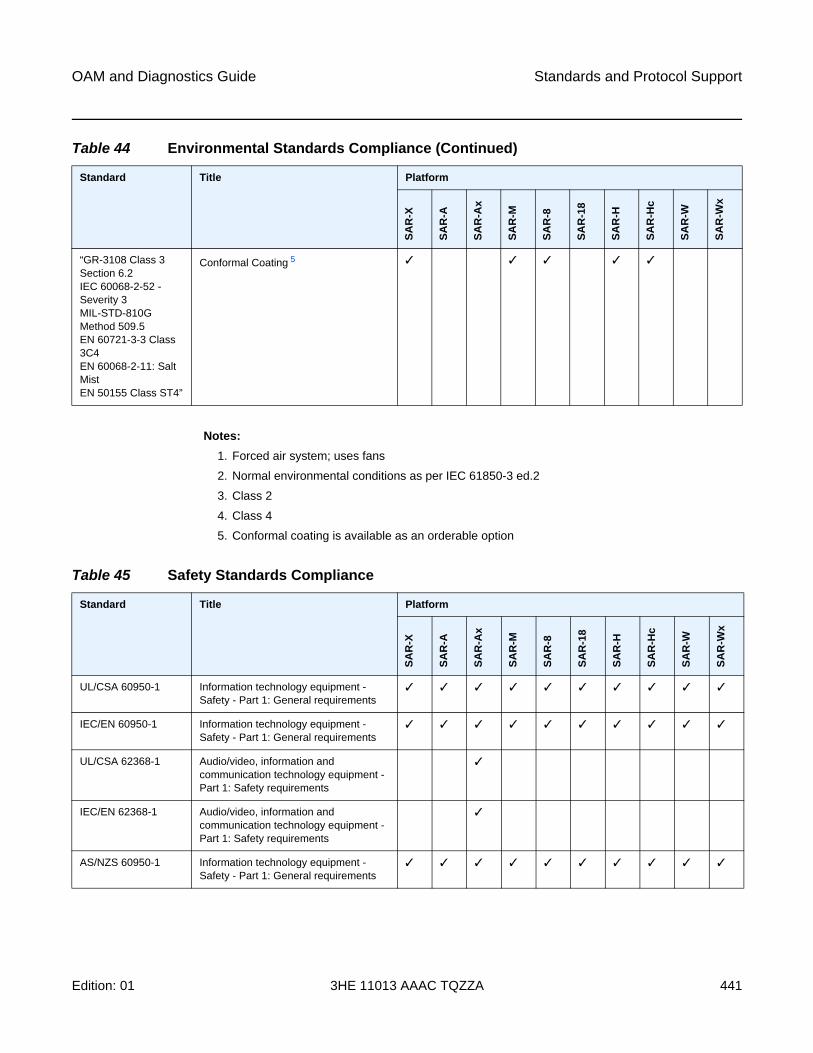
OAM and Diagnostics Guide Standards and Protocol Support
Edition: 01 3HE 11013 AAAC TQZZA 441
Notes:
1. Forced air system; uses fans
2. Normal environmental conditions as per IEC 61850-3 ed.2
3. Class 2
4. Class 4
5. Conformal coating is available as an orderable option
“GR-3108 Class 3 Section 6.2IEC 60068-2-52 - Severity 3MIL-STD-810G Method 509.5EN 60721-3-3 Class 3C4EN 60068-2-11: Salt MistEN 50155 Class ST4”
Conformal Coating 5 ✓ ✓ ✓ ✓ ✓
Table 44 Environmental Standards Compliance (Continued)
Standard Title Platform
SA
R-X
SA
R-A
SA
R-A
x
SA
R-M
SA
R-8
SA
R-1
8
SA
R-H
SA
R-H
c
SA
R-W
SA
R-W
x
Table 45 Safety Standards Compliance
Standard Title Platform
SA
R-X
SA
R-A
SA
R-A
x
SA
R-M
SA
R-8
SA
R-1
8
SA
R-H
SA
R-H
c
SA
R-W
SA
R-W
x
UL/CSA 60950-1 Information technology equipment - Safety - Part 1: General requirements
✓ ✓ ✓ ✓ ✓ ✓ ✓ ✓ ✓ ✓
IEC/EN 60950-1 Information technology equipment - Safety - Part 1: General requirements
✓ ✓ ✓ ✓ ✓ ✓ ✓ ✓ ✓ ✓
UL/CSA 62368-1 Audio/video, information and communication technology equipment - Part 1: Safety requirements
✓
IEC/EN 62368-1 Audio/video, information and communication technology equipment - Part 1: Safety requirements
✓
AS/NZS 60950-1 Information technology equipment - Safety - Part 1: General requirements
✓ ✓ ✓ ✓ ✓ ✓ ✓ ✓ ✓ ✓
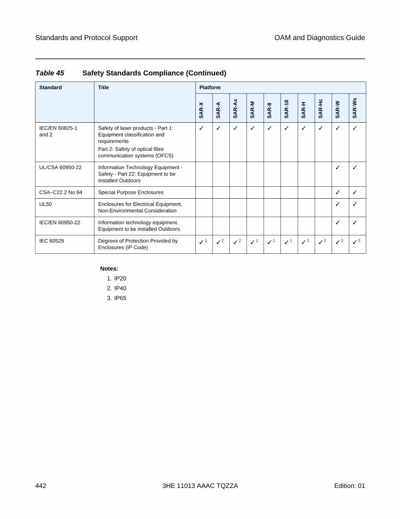
Standards and Protocol Support
442
OAM and Diagnostics Guide
3HE 11013 AAAC TQZZA Edition: 01
Notes:
1. IP20
2. IP40
3. IP65
IEC/EN 60825-1 and 2
Safety of laser products - Part 1: Equipment classification and requirements
Part 2: Safety of optical fibre communication systems (OFCS)
✓ ✓ ✓ ✓ ✓ ✓ ✓ ✓ ✓ ✓
UL/CSA 60950-22 Information Technology Equipment - Safety - Part 22: Equipment to be Installed Outdoors
✓ ✓
CSA–C22.2 No.94 Special Purpose Enclosures ✓ ✓
UL50 Enclosures for Electrical Equipment, Non-Environmental Consideration
✓ ✓
IEC/EN 60950-22 Information technology equipment. Equipment to be installed Outdoors.
✓ ✓
IEC 60529 Degrees of Protection Provided by Enclosures (IP Code)
✓ 1 ✓ 2 ✓ 2 ✓ 1 ✓ 1 ✓ 1 ✓ 2 ✓ 2 ✓ 3 ✓ 3
Table 45 Safety Standards Compliance (Continued)
Standard Title Platform
SA
R-X
SA
R-A
SA
R-A
x
SA
R-M
SA
R-8
SA
R-1
8
SA
R-H
SA
R-H
c
SA
R-W
SA
R-W
x
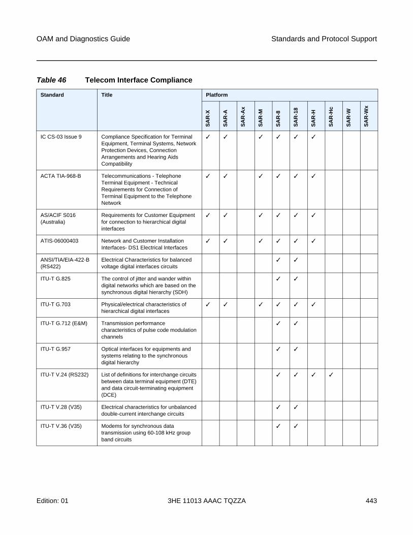
OAM and Diagnostics Guide Standards and Protocol Support
Edition: 01 3HE 11013 AAAC TQZZA 443
Table 46 Telecom Interface Compliance
Standard Title Platform
SA
R-X
SA
R-A
SA
R-A
x
SA
R-M
SA
R-8
SA
R-1
8
SA
R-H
SA
R-H
c
SA
R-W
SA
R-W
x
IC CS-03 Issue 9 Compliance Specification for Terminal Equipment, Terminal Systems, Network Protection Devices, Connection Arrangements and Hearing Aids Compatibility
✓ ✓ ✓ ✓ ✓ ✓
ACTA TIA-968-B Telecommunications - Telephone Terminal Equipment - Technical Requirements for Connection of Terminal Equipment to the Telephone Network
✓ ✓ ✓ ✓ ✓ ✓
AS/ACIF S016 (Australia)
Requirements for Customer Equipment for connection to hierarchical digital interfaces
✓ ✓ ✓ ✓ ✓ ✓
ATIS-06000403 Network and Customer Installation Interfaces- DS1 Electrical Interfaces
✓ ✓ ✓ ✓ ✓ ✓
ANSI/TIA/EIA-422-B (RS422)
Electrical Characteristics for balanced voltage digital interfaces circuits
✓ ✓
ITU-T G.825 The control of jitter and wander within digital networks which are based on the synchronous digital hierarchy (SDH)
✓ ✓
ITU-T G.703 Physical/electrical characteristics of hierarchical digital interfaces
✓ ✓ ✓ ✓ ✓ ✓
ITU-T G.712 (E&M) Transmission performance characteristics of pulse code modulation channels
✓ ✓
ITU-T G.957 Optical interfaces for equipments and systems relating to the synchronous digital hierarchy
✓ ✓
ITU-T V.24 (RS232) List of definitions for interchange circuits between data terminal equipment (DTE) and data circuit-terminating equipment (DCE)
✓ ✓ ✓ ✓
ITU-T V.28 (V35) Electrical characteristics for unbalanced double-current interchange circuits
✓ ✓
ITU-T V.36 (V35) Modems for synchronous data transmission using 60-108 kHz group band circuits
✓ ✓
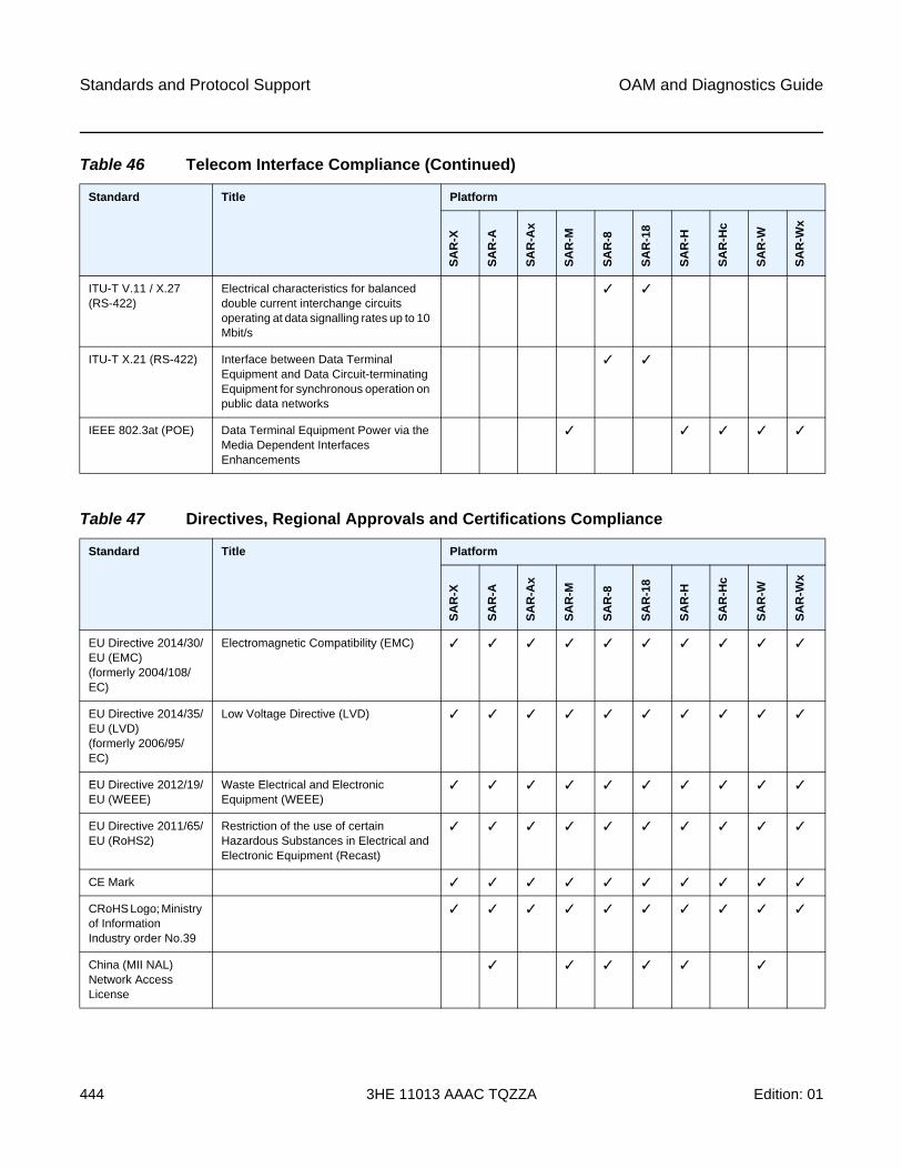
Standards and Protocol Support
444
OAM and Diagnostics Guide
3HE 11013 AAAC TQZZA Edition: 01
ITU-T V.11 / X.27 (RS-422)
Electrical characteristics for balanced double current interchange circuits operating at data signalling rates up to 10 Mbit/s
✓ ✓
ITU-T X.21 (RS-422) Interface between Data Terminal Equipment and Data Circuit-terminating Equipment for synchronous operation on public data networks
✓ ✓
IEEE 802.3at (POE) Data Terminal Equipment Power via the Media Dependent Interfaces Enhancements
✓ ✓ ✓ ✓ ✓
Table 46 Telecom Interface Compliance (Continued)
Standard Title Platform
SA
R-X
SA
R-A
SA
R-A
x
SA
R-M
SA
R-8
SA
R-1
8
SA
R-H
SA
R-H
c
SA
R-W
SA
R-W
x
Table 47 Directives, Regional Approvals and Certifications Compliance
Standard Title Platform
SA
R-X
SA
R-A
SA
R-A
x
SA
R-M
SA
R-8
SA
R-1
8
SA
R-H
SA
R-H
c
SA
R-W
SA
R-W
x
EU Directive 2014/30/EU (EMC) (formerly 2004/108/EC)
Electromagnetic Compatibility (EMC) ✓ ✓ ✓ ✓ ✓ ✓ ✓ ✓ ✓ ✓
EU Directive 2014/35/EU (LVD)(formerly 2006/95/EC)
Low Voltage Directive (LVD) ✓ ✓ ✓ ✓ ✓ ✓ ✓ ✓ ✓ ✓
EU Directive 2012/19/EU (WEEE)
Waste Electrical and Electronic Equipment (WEEE)
✓ ✓ ✓ ✓ ✓ ✓ ✓ ✓ ✓ ✓
EU Directive 2011/65/EU (RoHS2)
Restriction of the use of certain Hazardous Substances in Electrical and Electronic Equipment (Recast)
✓ ✓ ✓ ✓ ✓ ✓ ✓ ✓ ✓ ✓
CE Mark ✓ ✓ ✓ ✓ ✓ ✓ ✓ ✓ ✓ ✓
CRoHS Logo; Ministry of Information Industry order No.39
✓ ✓ ✓ ✓ ✓ ✓ ✓ ✓ ✓ ✓
China (MII NAL) Network Access License
✓ ✓ ✓ ✓ ✓ ✓
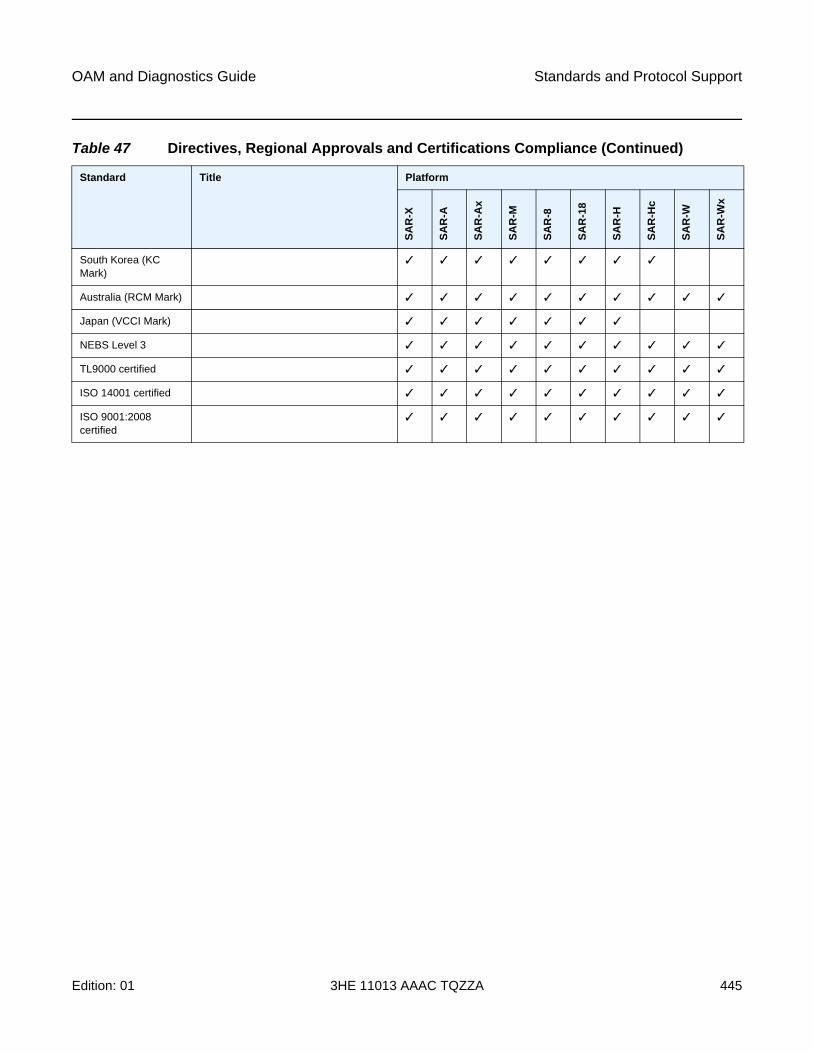
OAM and Diagnostics Guide Standards and Protocol Support
Edition: 01 3HE 11013 AAAC TQZZA 445
South Korea (KC Mark)
✓ ✓ ✓ ✓ ✓ ✓ ✓ ✓
Australia (RCM Mark) ✓ ✓ ✓ ✓ ✓ ✓ ✓ ✓ ✓ ✓
Japan (VCCI Mark) ✓ ✓ ✓ ✓ ✓ ✓ ✓
NEBS Level 3 ✓ ✓ ✓ ✓ ✓ ✓ ✓ ✓ ✓ ✓
TL9000 certified ✓ ✓ ✓ ✓ ✓ ✓ ✓ ✓ ✓ ✓
ISO 14001 certified ✓ ✓ ✓ ✓ ✓ ✓ ✓ ✓ ✓ ✓
ISO 9001:2008 certified
✓ ✓ ✓ ✓ ✓ ✓ ✓ ✓ ✓ ✓
Table 47 Directives, Regional Approvals and Certifications Compliance (Continued)
Standard Title Platform
SA
R-X
SA
R-A
SA
R-A
x
SA
R-M
SA
R-8
SA
R-1
8
SA
R-H
SA
R-H
c
SA
R-W
SA
R-W
x
Standards and Protocol Support
446
OAM and Diagnostics Guide
3HE 11013 AAAC TQZZA Edition: 01
Security Standards
FIPS 140-2—Federal Information Processing Standard publication 140-2, Security Requirements for Cryptographic Modules
Telecom Standards
ANSI/TIA/EIA-232-C—Interface Between Data Terminal Equipment and Data Circuit-Terminating Equipment Employing Serial Binary Data Interchange
IEEE 802.1ad—IEEE Standard for Local and Metropolitan Area Networks---Virtual Bridged Local Area Networks
IEEE 802.1ag—Service Layer OAM
IEEE 802.1p/q—VLAN Tagging
IEEE 802.3—10BaseT
IEEE 802.3ab—1000BaseT
IEEE 802.3ah—Ethernet OAM
IEEE 802.3u—100BaseTX
IEEE 802.3x —Flow Control
IEEE 802.3z—1000BaseSX/LX
IEEE 802.3-2008—Revised base standard
IEEE 802.1AX-2008—Link Aggregation Task Force (transferred from IEEE 802.3ad)
IEEE C37.94-2002—N Times 64 Kilobit Per Second Optical Fiber Interfaces Between Teleprotection and Multiplexer Equipment
ITU-T G.704—Synchronous frame structures used at 1544, 6312, 2048, 8448 and 44 736 kbit/s hierarchical levels
ITU-T G.707—Network node interface for the Synchronous Digital Hierarchy (SDH)
ITU-T G.984.1—Gigabit-capable passive optical networks (GPON): general characteristics
ITU-T Y.1564—Ethernet service activation test methodology
ITU-T Y.1731—OAM functions and mechanisms for Ethernet-based networks
Protocol Support
ATMAF-PHY-0086.001—Inverse Multiplexing for ATM (IMA)
af-tm-0121.000—Traffic Management Specification Version 4.1, March 1999
GR-1113-CORE—Bellcore, Asynchronous Transfer Mode (ATM) and ATM Adaptation Layer (AAL) Protocols Generic Requirements, Issue 1, July 1994
GR-1248-CORE—Generic Requirements for Operations of ATM Network Elements (NEs). Issue 3 June 1996
OAM and Diagnostics Guide Standards and Protocol Support
Edition: 01 3HE 11013 AAAC TQZZA 447
ITU-T Recommendation I.432.1—B-ISDN user-network interface - Physical layer specification: General characteristics
ITU-T Recommendation I.610—B-ISDN Operation and Maintenance Principles and Functions version 11/95
RFC 2514—Definitions of Textual Conventions and OBJECT_IDENTITIES for ATM Management, February 1999
RFC 2515—Definition of Managed Objects for ATM Management, February 1999
RFC 2684—Multiprotocol Encapsulation over ATM Adaptation Layer 5
BFDdraft-ietf-bfd-mib-00.txt—Bidirectional Forwarding Detection Management
Information Base
draft-ietf-bfd-base-o5.txt—Bidirectional Forwarding Detection
draft-ietf-bfd-v4v6-1hop-06.txt—BFD IPv4 and IPv6 (Single Hop)
draft-ietf-bfd-multihop-06.txt—BFD for Multi-hop Paths
BGPRFC 1397—BGP Default Route Advertisement
RFC 1997—BGP Communities Attribute
RFC 2385—Protection of BGP Sessions via the TCP MD5 Signature Option
RFC 2439—BGP Route Flap Dampening
RFC 2547bis—BGP/MPLS VPNs
RFC 2918—Route Refresh Capability for BGP-4
RFC 3107—Carrying Label Information in BGP-4
RFC 3392—Capabilities Advertisement with BGP-4
RFC 4271—BGP-4 (previously RFC 1771)
RFC 4360—BGP Extended Communities Attribute
RFC 4364—BGP/MPLS IP Virtual Private Networks (VPNs) (previously RFC 2574bis BGP/MPLS VPNs)
RFC 4456—BGP Route Reflection: Alternative to Full-mesh IBGP (previously RFC 1966 and RFC 2796)
RFC 4486—Subcodes for BGP Cease Notification Message
RFC 4684—Constrained Route Distribution for Border Gateway Protocol/MultiProtocol Label Switching (BGP/MPLS) Internet Protocol (IP) Virtual Private Networks (VPNs)
RFC 4724—Graceful Restart Mechanism for BGP - GR Helper
RFC 4760—Multi-protocol Extensions for BGP (previously RFC 2858)
RFC 4893—BGP Support for Four-octet AS Number Space
RFC 6513—Multicast in MPLS/BGP IP VPNs
Standards and Protocol Support
448
OAM and Diagnostics Guide
3HE 11013 AAAC TQZZA Edition: 01
RFC 6514—BGP Encodings and Procedures for Multicast in MPLS/BGP IP VPNs
draft-ietf-idr-add-paths-04.txt—Advertisement of Multiple Paths in BGP
draft-ietf-idr-add-paths-guidelines-00.txt—Best Practices for Advertisement of Multiple Paths in BGP
DHCP/DHCPv6RFC 1534—Interoperation between DHCP and BOOTP
RFC 2131—Dynamic Host Configuration Protocol (REV)
RFC 2132—DHCP Options and BOOTP Vendor Extensions
RFC 3046—DHCP Relay Agent Information Option (Option 82)
RFC 3315—Dynamic Host Configuration Protocol for IPv6
RFC 3736—Stateless Dynamic Host Configuration Protocol (DHCP) Service for IPv6
Differentiated ServicesRFC 2474—Definition of the DS Field in the IPv4 and IPv6 Headers
RFC 2597—Assured Forwarding PHB Group
RFC 2598—An Expedited Forwarding PHB
RFC 3140—Per-Hop Behavior Identification Codes
Digital Data Network ManagementV.35
RS-232 (also known as EIA/TIA-232)
X.21
DSL ModulesIEEE 802.2 LLC/SNAP bridged encapsulation while operating in ATM bonded mode
ITU-T G.991.2 Annex A, B, F and ITU-T G.991.2 Amendment 2 Annex G—SHDSL standards compliance
ITU-T G.991.2 Appendix F and G—Support for up to 5696 Kb/s per pair
ITU-T G.992.1 (ADSL)
ITU-T G.992.3 (G.dmt.bis), Annex A, B, J, M
ITU-T G.992.3 Annex K.2 (ADSL2)
ITU-T G.992.5, Annex A, B, J, M
ITU-T G.992.5 Annex K (ADSL2+)
ITU-T G.993.2 Amendment 1—Seamless Rate Adaptation
ITU-T G.993.2 Annex A and Annex B—xDSL Standards Compliance (ADSL2/2+ and VDSL2)
ITU-T G.993.2 Annex K.3—Supported Transport Protocol Specific Transmission Convergence functions
ITU G.994.1 (2/07) Amendment 1 and 2—G.hs Handshake
OAM and Diagnostics Guide Standards and Protocol Support
Edition: 01 3HE 11013 AAAC TQZZA 449
ITU-T G.998.2—SHDSL 4-pair EFM bonding
ITU-T G.998.4 G.inp—Physical layer retransmission
ITU-T Y.1564 Ethernet service activation test methodology
TR-060—SHDSL rate and reach
TR112 (U-R2 Deutsche Telekom AG) Version 7.0 and report of Self-Test-Result (ATU-T Register#3)
ECMPRFC 2992—Analysis of an Equal-Cost Multi-Path Algorithm
Frame RelayANSI T1.617 Annex D—Signalling Specification For Frame Relay Bearer Service
ITU-T Q.922 Annex A—Digital Subscriber Signalling System No. 1 (DSS1) data link layer - ISDN data link layer specification for frame mode bearer services
FRF.1.2—PVC User-to-Network Interface (UNI) Implementation Agreement
FRF.12—Frame Relay Fragmentation Implementation Agreement
RFC 2427—Multiprotocol Interconnect over Frame Relay
GRERFC 2784—Generic Routing Encapsulation (GRE)
IPSecITU-T X.690 (2002)—ASN.1 encoding rules: Specification of Basic Encoding Rules
(BER), Canonical Encoding Rules (CER) and Distinguished Encoding Rules (DER)
PKCS #12 Personal Information Exchange Syntax Standard
RFC 2315—PKCS #7: Cryptographic Message Syntax
RFC 2401—Security Architecture for the Internet Protocol
RFC 2409—The Internet Key Exchange (IKE)
RFC 2986—PKCS #10: Certification Request Syntax Specification
RFC 3706—A Traffic-Based Method of Detecting Dead Internet Key Exchange (IKE) Peers
RFC 3947—Negotiation of NAT-Traversal in the IKE
RFC 3948—UDP Encapsulation of IPsec ESP Packets
RFC 4303—IP Encapsulating Security Payload (ESP)
RFC 4210—Internet X.509 Public Key Infrastructure Certificate Management Protocol (CMP)
RFC 4211—Internet X.509 Public Key Infrastructure Certificate Request Message Format (CRMF)
RFC 4945—The Internet IP Security PKI Profile of IKEv1/ISAKMP, IKEv2, and PKIX
Standards and Protocol Support
450
OAM and Diagnostics Guide
3HE 11013 AAAC TQZZA Edition: 01
RFC 5280—Internet X.509 Public Key Infrastructure Certificate and Certificate Revocation List (CRL) Profile
RFC 5996—Internet Key Exchange Protocol Version 2 (IKEv2)
IPv6RFC 2460—Internet Protocol, Version 6 (IPv6) Specification
RFC 2462—IPv6 Stateless Address Autoconfiguration
RFC 2464—Transmission of IPv6 Packets over Ethernet Networks
RFC 3587—IPv6 Global Unicast Address Format
RFC 3595—Textual Conventions for IPv6 Flow Label
RFC 4007—IPv6 Scoped Address Architecture
RFC 4193—Unique Local IPv6 Unicast Addresses
RFC 4291—IPv6 Addressing Architecture
RFC 4443—Internet Control Message Protocol (ICMPv6) for the Internet Protocol Version 6 Specification
RFC 4649—DHCPv6 Relay Agent Remote-ID Option
RFC 4861—Neighbor Discovery for IP version 6 (IPv6)
RFC 5095—Deprecation of Type 0 Routing Headers in IPv6
RFC 5952—A Recommendation for IPv6 Address Text Representation
IS-ISRFC 1142—OSI IS-IS Intra-domain Routing Protocol (ISO 10589)
RFC 1195—Use of OSI IS-IS for routing in TCP/IP & dual environments
RFC 2763—Dynamic Hostname Exchange for IS-IS
RFC 2966—Domain-wide Prefix Distribution with Two-Level IS-IS
RFC 2973—IS-IS Mesh Groups
RFC 3373—Three-Way Handshake for Intermediate System to Intermediate System (IS-IS) Point-to-Point Adjacencies
RFC 3567—Intermediate System to Intermediate System (IS-IS) Cryptographic Authentication
RFC 3719—Recommendations for Interoperable Networks using IS-IS
RFC 3784—Intermediate System to Intermediate System (IS-IS) Extensions for Traffic Engineering (TE)
RFC 3787—Recommendations for Interoperable IP Networks
RFC 4205 for Shared Risk Link Group (SRLG) TLV
RFC 5304—IS-IS Cryptographic Authentication
RFC 5308—Routing IPv6 with IS-IS
RFC 5309—Point-to-Point Operation over LAN in Link State Routing Protocols
RFC 5310—IS-IS Generic Cryptographic Authentication
OAM and Diagnostics Guide Standards and Protocol Support
Edition: 01 3HE 11013 AAAC TQZZA 451
LDPRFC 5036—LDP Specification
RFC 5283—LDP Extension for Inter-Area Label Switched Paths
RFC 5443—LDP IGP Synchronization
RFC 6388—Label Distribution Protocol Extensions for Point-to-Multipoint and Multipoint-to-Multipoint Label Switched Paths
RFC 6512—Using Multipoint LDP When the Backbone Has No Route to the Root
draft-pdutta-mpls-mldp-up-redundancy-00.txt—Upstream LSR Redundancy for Multi-point LDP Tunnels
LDP and IP FRRRFC 5286—Basic Specification for IP Fast Reroute: Loop-Free Alternates
MPLSRFC 3031—MPLS Architecture
RFC 3032—MPLS Label Stack Encoding
RFC 3815—Definitions of Managed Objects for the Multiprotocol Label Switching (MPLS), Label Distribution Protocol (LDP)
RFC 6790—The Use of Entropy Labels in MPLS Forwarding
MPLS – OAMRFC 4379—Detecting Multi-Protocol Label Switched (MPLS) Data Plane Failures
RFC 6424— Mechanism for Performing Label Switched Path Ping (LSP Ping) over MPLS Tunnels
MulticastRFC 3956—Embedding the Rendezvous Point (RP) Address in an IPv6 Multicast
Address
RFC 3973—Protocol Independent Multicast - Dense Mode (PIM-DM): Protocol Specification (Revised)
RFC 4610—Anycast-RP Using Protocol Independent Multicast (PIM), which is similar to RFC 3446—Anycast Rendevous Point (RP) mechanism using Protocol Independent Multicast (PIM) and Multicast Source Discovery Protocol (MSDP)
RFC 6514—BGP Encodings and Procedures for Multicast in MPLS/IP VPNs
cisco-ipmulticast/pim-autorp-spec—Auto-RP: Automatic discovery of Group-to-RP mappings for IP multicast, which is similar to RFC 5059—Bootstrap Router (BSR) Mechanism for Protocol Independent Multicast (PIM)
draft-ietf-l2vpn-vpls-pim-snooping-07—Protocol Independent Multicast (PIM) over Virtual Private LAN Service (VPLS)
draft-ietf-mboned-msdp-deploy-nn.txt—Multicast Source Discovery Protocol (MSDP) Deployment Scenarios
Standards and Protocol Support
452
OAM and Diagnostics Guide
3HE 11013 AAAC TQZZA Edition: 01
Network ManagementIANA-IFType-MIB
ITU-T X.721—Information technology- OSI-Structure of Management Information
ITU-T X.734—Information technology- OSI-Systems Management: Event Report Management Function
M.3100/3120—Equipment and Connection Models
RFC 1157—SNMPv1
RFC 1850—OSPF-MIB
RFC 1907—SNMPv2-MIB
RFC 2011—IP-MIB
RFC 2012—TCP-MIB
RFC 2013—UDP-MIB
RFC 2030—Simple Network Time Protocol (SNTP) Version 4 for IPv4, IPv6 and OSI
RFC 2096—IP-FORWARD-MIB
RFC 2138—RADIUS
RFC 2206—RSVP-MIB
RFC 2571—SNMP-FRAMEWORKMIB
RFC 2572—SNMP-MPD-MIB
RFC 2573—SNMP-TARGET-&-NOTIFICATION-MIB
RFC 2574—SNMP-USER-BASED-SMMIB
RFC 2575—SNMP-VIEW-BASED ACM-MIB
RFC 2576—SNMP-COMMUNITY-MIB
RFC 2588—SONET-MIB
RFC 2665—EtherLike-MIB
RFC 2819—RMON-MIB
RFC 2863—IF-MIB
RFC 2864—INVERTED-STACK-MIB
RFC 3014—NOTIFICATION-LOG MIB
RFC 3164—The BSD Syslog Protocol
RFC 3273—HCRMON-MIB
RFC 3411—An Architecture for Describing Simple Network Management Protocol (SNMP) Management Frameworks
RFC 3412—Message Processing and Dispatching for the Simple Network Management Protocol (SNMP)
RFC 3413—Simple Network Management Protocol (SNMP) Applications
RFC 3414—User-based Security Model (USM) for version 3 of the Simple Network Management Protocol (SNMPv3)
RFC 3418—SNMP MIB
OAM and Diagnostics Guide Standards and Protocol Support
Edition: 01 3HE 11013 AAAC TQZZA 453
draft-ietf-disman-alarm-mib-04.txt
draft-ietf-mpls-ldp-mib-07.txt
draft-ietf-ospf-mib-update-04.txt
draft-ietf-mpls-lsr-mib-06.txt
draft-ietf-mpls-te-mib-04.txt
TMF 509/613—Network Connectivity Model
OSPFRFC 1765—OSPF Database Overflow
RFC 2328—OSPF Version 2
RFC 2370—Opaque LSA Support
RFC 2740—OSPF for IPv6
RFC 3101—OSPF NSSA Option
RFC 3137—OSPF Stub Router Advertisement
RFC 3509—Alternative Implementations of OSPF Area Border Routers
RFC 3623—Graceful OSPF Restart (support for Helper mode)
RFC 3630—Traffic Engineering (TE) Extensions to OSPF
RFC 4203 for Shared Risk Link Group (SRLG) sub-TLV
RFC 4577—OSPF as the Provider/Customer Edge Protocol for BGP/MPLS IP Virtual Private Networks (VPNs) (support for basic OSPF at PE-CE links)
OSPFv3RFC 4552—Authentication/Confidentiality for OSPFv3
PPPRFC 1332—PPP Internet Protocol Control Protocol (IPCP)
RFC 1570—PPP LCP Extensions
RFC 1619—PPP over SONET/SDH
RFC 1661—The Point-to-Point Protocol (PPP)
RFC 1662—PPP in HDLC-like Framing
RFC 1989—PPP Link Quality Monitoring
RFC 1990—The PPP Multilink Protocol (MP)
RFC 2686—The Multi-Class Extension to Multi-Link PPP
PseudowiresMetro Ethernet Forum—Implementation Agreement for the Emulation of PDH
Circuits over Metro Ethernet Networks
RFC 3550—RTP: A Transport Protocol for Real-Time Applications
RFC 3985—Pseudo Wire Emulation Edge-to-Edge (PWE3) Architecture
Standards and Protocol Support
454
OAM and Diagnostics Guide
3HE 11013 AAAC TQZZA Edition: 01
RFC 4385—Pseudowire Emulation Edge-to-Edge (PWE3) Control Word for Use over an MPLS PSN
RFC 4446—IANA Allocation for PWE3
RFC 4447—Pseudowire Setup and Maintenance Using the Label Distribution Protocol (LDP)
RFC 4448—Encapsulation Methods for Transport of Ethernet over MPLS Networks
RFC 4553—Structure-Agnostic Time Division Multiplexing (TDM) over Packet (SAToP)
RFC 4717—Encapsulation Methods for Transport of Asynchronous Transfer Mode (ATM) over MPLS Networks
RFC 4618—Encapsulation Methods for Transport of PPP/High-Level Data Link Control (HDLC) over MPLS Networks
RFC 4619—Encapsulation Methods for Transport of Frame Relay over Multiprotocol Label Switching (MPLS) Networks
RFC 4816—Pseudowire Emulation Edge-to-Edge (PWE3) Asynchronous Transfer Mode (ATM) Transparent Cell Transport Service
RFC 5085—Pseudowire Virtual Circuit Connectivity Verification (VCCV): A Control Channel for Pseudowires
RFC 5086—Structure-Aware Time Division Multiplexed (TDM) Circuit Emulation Service over Packet Switched Network (CESoPSN)
draft-ietf-pwe3-redundancy-02.txt—Pseudowire (PW) Redundancy
RIPRFC 1058—Routing Information Protocol
RFC 2453—RIP Version 2
RADIUSRFC 2865—Remote Authentication Dial In User Service
RFC 2866—RADIUS Accounting
RSVP-TE and FRRRFC 2430—A Provider Architecture for DiffServ & TE
RFC 2961—RSVP Refresh Overhead Reduction Extensions
RFC 2702—Requirements for Traffic Engineering over MPLS
RFC 2747—RSVP Cryptographic Authentication
RFC 3097—RSVP Cryptographic Authentication - Updated Message Type Value
RFC 3209—Extensions to RSVP for LSP Tunnels
RFC 3210—Applicability Statement for Extensions to RSVP for LSP Tunnels
RFC 3477—Signalling Unnumbered Links in Resource ReSerVation Protocol - Traffic Engineering (RSVP-TE)
OAM and Diagnostics Guide Standards and Protocol Support
Edition: 01 3HE 11013 AAAC TQZZA 455
RFC 4090—Fast Reroute Extensions to RSVP-TE for LSP Tunnels
RFC 5440—Path Computation Element (PCE) Communication Protocol (PCEP)
draft-ietf-pce-stateful-pce—PCEP Extensions for Stateful PCE
draft-ietf-pce-segment-routing—PCEP Extensions for Segment Routing
draft-alvarez-pce-path-profiles—PCE Path Profiles
SONET/SDHGR-253-CORE—SONET Transport Systems: Common Generic Criteria. Issue 3,
September 2000
ITU-T Recommendation G.841—Telecommunication Standardization Section of ITU, Types and Characteristics of SDH Networks Protection Architecture, issued in October 1998 and as augmented by Corrigendum1 issued in July 2002
SSHdraft-ietf-secsh-architecture.txt—SSH Protocol Architecture
draft-ietf-secsh-userauth.txt—SSH Authentication Protocol
draft-ietf-secsh-transport.txt—SSH Transport Layer Protocol
draft-ietf-secsh-connection.txt—SSH Connection Protocol
draft-ietf-secsh- newmodes.txt—SSH Transport Layer Encryption Modes
draft-ietf-secsh-filexfer-13.txt—SSH File Transfer Protocol
SynchronizationG.781—Synchronization layer functions, 2001/09/17
G.803—Architecture of transport networks based on the synchronous digital hierarchy (SDH)
G.813—Timing characteristics of SDH equipment slave clocks (SEC)
G.823—The control of jitter and wander within digital networks which are based on the 2048 kbit/s hierarchy, 2003/03/16
G.824—The control of jitter and wander within digital networks which are based on the 1544 kbit/s hierarchy, 2003/03/16
G.8261—Timing and synchronization aspects in packet networks
G.8262—Timing characteristics of synchronous Ethernet equipment slave clock
GR 1244 CORE—Clocks for the Synchronized Network: Common Generic Criteria
IEEE Std 1588-2008—IEEE Standard for a Precision Clock Synchronization Protocol for Networked Measurement and Control Systems
ITU-T G.8264—Telecommunication Standardization Section of ITU, Distribution of timing information through packet networks, issued 10/2008
ITU-T G.8265.1—Telecommunication Standardization Section of ITU, Precision time protocol telecom profile for frequency synchronization, issued 10/2010
Standards and Protocol Support
456
OAM and Diagnostics Guide
3HE 11013 AAAC TQZZA Edition: 01
ITU-T G.8275.1—Telecommunication Standardization Section of ITU, Precision time protocol telecom profile for phase/time synchronization with full timing support from the network, issued 07/2014
RFC 5905—Network Time Protocol Version 4: Protocol and Algorithms Specification
TACACS+IETF draft-grant-tacacs-02.txt—The TACACS+ Protocol
TCP/IPRFC 768—User Datagram Protocol
RFC 791—Internet Protocol
RFC 792—Internet Control Message Protocol
RFC 793—Transmission Control Protocol
RFC 826—Ethernet Address Resolution Protocol
RFC 854—Telnet Protocol Specification
RFC 1350—The TFTP Protocol (Rev. 2)
RFC 1812—Requirements for IPv4 Routers
TWAMPRFC 5357—A Two-Way Active Measurement Protocol (TWAMP)
VPLSRFC 4762—Virtual Private LAN Services Using LDP
VRRPRFC 2787—Definitions of Managed Objects for the Virtual Router Redundancy
Protocol
RFC 3768 Virtual Router Redundancy Protocol
RFC 5798 Virtual Router Redundancy Protocol Version 3 for IPv4 and IPv6
Proprietary MIBs
TIMETRA-ATM-MIB.mib
TIMETRA-CAPABILITY-7705-V1.mib
TIMETRA-CHASSIS-MIB.mib
TIMETRA-CLEAR-MIB.mib
TIMETRA-FILTER-MIB.mib
TIMETRA-GLOBAL-MIB.mib
TIMETRA-LAG-MIB.mib
TIMETRA-LDP-MIB.mib
TIMETRA-LOG-MIB.mib
OAM and Diagnostics Guide Standards and Protocol Support
Edition: 01 3HE 11013 AAAC TQZZA 457
TIMETRA-MPLS-MIB.mib
TIMETRA-OAM-TEST-MIB.mib
TIMETRA-PORT-MIB.mib
TIMETRA-PPP-MIB.mib
TIMETRA-QOS-MIB.mib
TIMETRA-ROUTE-POLICY-MIB.mib
TIMETRA-RSVP-MIB.mib
TIMETRA-SAP-MIB.mib
TIMETRA-SDP-MIB.mib
TIMETRA-SECURITY-MIB.mib
TIMETRA-SERV-MIB.mib
TIMETRA-SYSTEM-MIB.mib
TIMETRA-TC-MIB.mib
TIMETRA-VRRP-MIB.mib

Standards and Protocol Support
458
OAM and Diagnostics Guide
3HE 11013 AAAC TQZZA Edition: 01

Customer Document and Product Support
Customer documentationCustomer Documentation Welcome Page
Technical SupportProduct Support Portal
Documentation feedbackCustomer Documentation Feedback

© 2016-2017 Nokia.3HE 11013 AAAC TQZZA