Embed Size (px)
Citation preview
Alcatel-Lucent 7705SERVICE AGGREGATION ROUTER OS | RELEASE 2.0R O U T I N G P R O T O C O L S G U I D E
Alcatel-Lucent ProprietaryThis document contains proprietary information of Alcatel-Lucent and is not to be disclosedor used except in accordance with applicable agreements.Copyright 2009 © Alcatel-Lucent. All rights reserved.
When printed by Alcatel-Lucent, this document is printed on recycled paper.
Alcatel-Lucent assumes no responsibility for the accuracy of the information presented, which is subject to change without notice.
Alcatel, Lucent, Alcatel-Lucent and the Alcatel-Lucent logo are trademarks of Alcatel-Lucent. All other trademarks are the property of their respective owners.
Copyright 2009 Alcatel-Lucent.All rights reserved.
Disclaimers
Alcatel-Lucent products are intended for commercial uses. Without the appropriate network design engineering, they must not be sold, licensed or otherwise distributed for use in any hazardous environments requiring fail-safe performance, such as in the operation of nuclear facilities, aircraft navigation or communication systems, air traffic control, direct life-support machines, or weapons systems, in which the failure of products could lead directly to death, personal injury, or severe physical or environmental damage. The customer hereby agrees that the use, sale, license or other distribution of the products for any such application without the prior written consent of Alcatel-Lucent, shall be at the customer's sole risk. The customer hereby agrees to defend and hold Alcatel-Lucent harmless from any claims for loss, cost, damage, expense or liability that may arise out of or in connection with the use, sale, license or other distribution of the products in such applications.
This document may contain information regarding the use and installation of non-Alcatel-Lucent products. Please note that this information is provided as a courtesy to assist you. While Alcatel-Lucent tries to ensure that this information accurately reflects information provided by the supplier, please refer to the materials provided with any non-Alcatel-Lucent product and contact the supplier for confirmation. Alcatel-Lucent assumes no responsibility or liability for incorrect or incomplete information provided about non-Alcatel-Lucent products.
However, this does not constitute a representation or warranty. The warranties provided for Alcatel-Lucent products, if any, are set forth in contractual documentation entered into by Alcatel-Lucent and its customers.
This document was originally written in English. If there is any conflict or inconsistency between the English version and any other version of a document, the English version shall prevail.
Table of Contents
Preface . . . . . . . . . . . . . . . . . . . . . . . . . . . . . . . . . . . . . . . . . . . . . . . . . . . . . . . . . . . . . . . . . . . . . . . . . 19
Getting Started . . . . . . . . . . . . . . . . . . . . . . . . . . . . . . . . . . . . . . . . . . . . . . . . . . . . . . . . . . . . . . . . . . . 21Alcatel-Lucent 7705 SAR Routing Configuration Process . . . . . . . . . . . . . . . . . . . . . . . . . . . . . . . . . . . . . . . . 21
Notes on 7705 SAR-8 and 7705 SAR-F . . . . . . . . . . . . . . . . . . . . . . . . . . . . . . . . . . . . . . . . . . . . . . . . . . . 22
OSPF . . . . . . . . . . . . . . . . . . . . . . . . . . . . . . . . . . . . . . . . . . . . . . . . . . . . . . . . . . . . . . . . . . . . . . . . . . . 25Overview of OSPF . . . . . . . . . . . . . . . . . . . . . . . . . . . . . . . . . . . . . . . . . . . . . . . . . . . . . . . . . . . . . . . . . . . . . . 26
OSPF Areas . . . . . . . . . . . . . . . . . . . . . . . . . . . . . . . . . . . . . . . . . . . . . . . . . . . . . . . . . . . . . . . . . . . . . . . . 27Backbone Area . . . . . . . . . . . . . . . . . . . . . . . . . . . . . . . . . . . . . . . . . . . . . . . . . . . . . . . . . . . . . . . . . . . . 28Stub Area . . . . . . . . . . . . . . . . . . . . . . . . . . . . . . . . . . . . . . . . . . . . . . . . . . . . . . . . . . . . . . . . . . . . . . . . 29Not-So-Stubby Area . . . . . . . . . . . . . . . . . . . . . . . . . . . . . . . . . . . . . . . . . . . . . . . . . . . . . . . . . . . . . . . . 30
Virtual Links . . . . . . . . . . . . . . . . . . . . . . . . . . . . . . . . . . . . . . . . . . . . . . . . . . . . . . . . . . . . . . . . . . . . . . . . 30Neighbors and Adjacencies . . . . . . . . . . . . . . . . . . . . . . . . . . . . . . . . . . . . . . . . . . . . . . . . . . . . . . . . . . . . 31
Designated Routers and Backup Designated Routers . . . . . . . . . . . . . . . . . . . . . . . . . . . . . . . . . . . . . . 31Link-State Advertisements . . . . . . . . . . . . . . . . . . . . . . . . . . . . . . . . . . . . . . . . . . . . . . . . . . . . . . . . . . . . . 32Metrics . . . . . . . . . . . . . . . . . . . . . . . . . . . . . . . . . . . . . . . . . . . . . . . . . . . . . . . . . . . . . . . . . . . . . . . . . . . . 33Authentication . . . . . . . . . . . . . . . . . . . . . . . . . . . . . . . . . . . . . . . . . . . . . . . . . . . . . . . . . . . . . . . . . . . . . . . 34Route Redistribution and Summarization . . . . . . . . . . . . . . . . . . . . . . . . . . . . . . . . . . . . . . . . . . . . . . . . . . 34OSPF-TE Extensions . . . . . . . . . . . . . . . . . . . . . . . . . . . . . . . . . . . . . . . . . . . . . . . . . . . . . . . . . . . . . . . . . 35IP Subnets . . . . . . . . . . . . . . . . . . . . . . . . . . . . . . . . . . . . . . . . . . . . . . . . . . . . . . . . . . . . . . . . . . . . . . . . . 35OSPF Instances . . . . . . . . . . . . . . . . . . . . . . . . . . . . . . . . . . . . . . . . . . . . . . . . . . . . . . . . . . . . . . . . . . . . . 35Bidirectional Forwarding Detection (BFD) for OSPF . . . . . . . . . . . . . . . . . . . . . . . . . . . . . . . . . . . . . . . . . . 36Preconfiguration Requirements . . . . . . . . . . . . . . . . . . . . . . . . . . . . . . . . . . . . . . . . . . . . . . . . . . . . . . . . . 36
OSPF Configuration Process Overview . . . . . . . . . . . . . . . . . . . . . . . . . . . . . . . . . . . . . . . . . . . . . . . . . . . . . . 37Configuration Notes . . . . . . . . . . . . . . . . . . . . . . . . . . . . . . . . . . . . . . . . . . . . . . . . . . . . . . . . . . . . . . . . . . . . . 38
General . . . . . . . . . . . . . . . . . . . . . . . . . . . . . . . . . . . . . . . . . . . . . . . . . . . . . . . . . . . . . . . . . . . . . . . . . . . . 38Reference Sources . . . . . . . . . . . . . . . . . . . . . . . . . . . . . . . . . . . . . . . . . . . . . . . . . . . . . . . . . . . . . . . . . . . 38
Configuring OSPF with CLI . . . . . . . . . . . . . . . . . . . . . . . . . . . . . . . . . . . . . . . . . . . . . . . . . . . . . . . . . . . . . . . . 39OSPF Configuration Guidelines . . . . . . . . . . . . . . . . . . . . . . . . . . . . . . . . . . . . . . . . . . . . . . . . . . . . . . . . . . . . 40Basic OSPF Configuration . . . . . . . . . . . . . . . . . . . . . . . . . . . . . . . . . . . . . . . . . . . . . . . . . . . . . . . . . . . . . . . . 41
Configuring the Router ID . . . . . . . . . . . . . . . . . . . . . . . . . . . . . . . . . . . . . . . . . . . . . . . . . . . . . . . . . . . . . . 41Configuring an OSPF Area . . . . . . . . . . . . . . . . . . . . . . . . . . . . . . . . . . . . . . . . . . . . . . . . . . . . . . . . . . . . . 42Configuring an Interface . . . . . . . . . . . . . . . . . . . . . . . . . . . . . . . . . . . . . . . . . . . . . . . . . . . . . . . . . . . . . . . 43
Configuring Other OSPF Components . . . . . . . . . . . . . . . . . . . . . . . . . . . . . . . . . . . . . . . . . . . . . . . . . . . . . . . 45Configuring a Stub Area . . . . . . . . . . . . . . . . . . . . . . . . . . . . . . . . . . . . . . . . . . . . . . . . . . . . . . . . . . . . . . . 45Configuring a Not-So-Stubby Area . . . . . . . . . . . . . . . . . . . . . . . . . . . . . . . . . . . . . . . . . . . . . . . . . . . . . . . 46Configuring a Virtual Link . . . . . . . . . . . . . . . . . . . . . . . . . . . . . . . . . . . . . . . . . . . . . . . . . . . . . . . . . . . . . . 46Configuring Authentication . . . . . . . . . . . . . . . . . . . . . . . . . . . . . . . . . . . . . . . . . . . . . . . . . . . . . . . . . . . . . 48Assigning a Designated Router . . . . . . . . . . . . . . . . . . . . . . . . . . . . . . . . . . . . . . . . . . . . . . . . . . . . . . . . . 50Configuring Route Summaries . . . . . . . . . . . . . . . . . . . . . . . . . . . . . . . . . . . . . . . . . . . . . . . . . . . . . . . . . . 51Configuring Route Preferences . . . . . . . . . . . . . . . . . . . . . . . . . . . . . . . . . . . . . . . . . . . . . . . . . . . . . . . . . . 52
OSPF Configuration Management Tasks . . . . . . . . . . . . . . . . . . . . . . . . . . . . . . . . . . . . . . . . . . . . . . . . . . . . . 54Modifying a Router ID . . . . . . . . . . . . . . . . . . . . . . . . . . . . . . . . . . . . . . . . . . . . . . . . . . . . . . . . . . . . . . . . . 54Deleting a Router ID . . . . . . . . . . . . . . . . . . . . . . . . . . . . . . . . . . . . . . . . . . . . . . . . . . . . . . . . . . . . . . . . . . 55Modifying OSPF Parameters . . . . . . . . . . . . . . . . . . . . . . . . . . . . . . . . . . . . . . . . . . . . . . . . . . . . . . . . . . . 55
7705 SAR OS Routing Protocols Guide Page 3

Table of Contents
OSPF Command Reference . . . . . . . . . . . . . . . . . . . . . . . . . . . . . . . . . . . . . . . . . . . . . . . . . . . . . . . . . . . . . . 57Command Hierarchies . . . . . . . . . . . . . . . . . . . . . . . . . . . . . . . . . . . . . . . . . . . . . . . . . . . . . . . . . . . . . . . . 57Command Descriptions . . . . . . . . . . . . . . . . . . . . . . . . . . . . . . . . . . . . . . . . . . . . . . . . . . . . . . . . . . . . . . . . 62
Configuration Commands . . . . . . . . . . . . . . . . . . . . . . . . . . . . . . . . . . . . . . . . . . . . . . . . . . . . . . . . . . . . 63Show Commands . . . . . . . . . . . . . . . . . . . . . . . . . . . . . . . . . . . . . . . . . . . . . . . . . . . . . . . . . . . . . . . . . . 90Clear Commands . . . . . . . . . . . . . . . . . . . . . . . . . . . . . . . . . . . . . . . . . . . . . . . . . . . . . . . . . . . . . . . . . 125Debug Commands . . . . . . . . . . . . . . . . . . . . . . . . . . . . . . . . . . . . . . . . . . . . . . . . . . . . . . . . . . . . . . . . 127
Standards and Protocol Support . . . . . . . . . . . . . . . . . . . . . . . . . . . . . . . . . . . . . . . . . . . . . . . . . . . 131
Page 4 7705 SAR OS Routing Protocols Guide

List of Tables
Getting Started . . . . . . . . . . . . . . . . . . . . . . . . . . . . . . . . . . . . . . . . . . . . . . . . . . . . . . . . . . . . . . . . . . . 21Table 1: Configuration Process . . . . . . . . . . . . . . . . . . . . . . . . . . . . . . . . . . . . . . . . . . . . . . . . . . . . . . . . . . . 21Table 2: 7705 SAR-8 and 7705 SAR-F Comparison . . . . . . . . . . . . . . . . . . . . . . . . . . . . . . . . . . . . . . . . . . . 22
OSPF . . . . . . . . . . . . . . . . . . . . . . . . . . . . . . . . . . . . . . . . . . . . . . . . . . . . . . . . . . . . . . . . . . . . . . . . . . . 25Table 3: LSA types . . . . . . . . . . . . . . . . . . . . . . . . . . . . . . . . . . . . . . . . . . . . . . . . . . . . . . . . . . . . . . . . . . . . . 32Table 4: Route Preference Defaults by Route Type . . . . . . . . . . . . . . . . . . . . . . . . . . . . . . . . . . . . . . . . . . . . 52Table 5: Route Preference Defaults by Route Type . . . . . . . . . . . . . . . . . . . . . . . . . . . . . . . . . . . . . . . . . . . . 68Table 6: Show Area Output Fields . . . . . . . . . . . . . . . . . . . . . . . . . . . . . . . . . . . . . . . . . . . . . . . . . . . . . . . . . 90Table 7: Show Database Output Fields . . . . . . . . . . . . . . . . . . . . . . . . . . . . . . . . . . . . . . . . . . . . . . . . . . . . . 93Table 8: Show Interface Output Fields . . . . . . . . . . . . . . . . . . . . . . . . . . . . . . . . . . . . . . . . . . . . . . . . . . . . . . 96Table 9: Show Detailed Interface Output Fields . . . . . . . . . . . . . . . . . . . . . . . . . . . . . . . . . . . . . . . . . . . . . . . 98Table 10: Show Neighbor Output Fields . . . . . . . . . . . . . . . . . . . . . . . . . . . . . . . . . . . . . . . . . . . . . . . . . . . . . 104Table 11: Show Detailed Neighbor Output Fields . . . . . . . . . . . . . . . . . . . . . . . . . . . . . . . . . . . . . . . . . . . . . 106Table 12: Show Area Range Output Fields . . . . . . . . . . . . . . . . . . . . . . . . . . . . . . . . . . . . . . . . . . . . . . . . . . 109Table 13: Show SPF Output Fields . . . . . . . . . . . . . . . . . . . . . . . . . . . . . . . . . . . . . . . . . . . . . . . . . . . . . . . . 110Table 14: Show OSPF Statistics Output Fields . . . . . . . . . . . . . . . . . . . . . . . . . . . . . . . . . . . . . . . . . . . . . . . 112Table 15: Show OSPF Status Output Fields . . . . . . . . . . . . . . . . . . . . . . . . . . . . . . . . . . . . . . . . . . . . . . . . . 115Table 16: Show Virtual Link Output Fields . . . . . . . . . . . . . . . . . . . . . . . . . . . . . . . . . . . . . . . . . . . . . . . . . . . 118Table 17: Show Virtual Neighbor Output Fields . . . . . . . . . . . . . . . . . . . . . . . . . . . . . . . . . . . . . . . . . . . . . . . 122
7705 SAR OS Routing Protocols Guide Page 5

List of Tables
Page 6 7705 SAR OS Routing Protocols Guide
List of Figures
OSPF . . . . . . . . . . . . . . . . . . . . . . . . . . . . . . . . . . . . . . . . . . . . . . . . . . . . . . . . . . . . . . . . . . . . . . . . . . . 25Figure 1: Backbone Area . . . . . . . . . . . . . . . . . . . . . . . . . . . . . . . . . . . . . . . . . . . . . . . . . . . . . . . . . . . . . . . . . 29Figure 2: OSPF Configuration Process . . . . . . . . . . . . . . . . . . . . . . . . . . . . . . . . . . . . . . . . . . . . . . . . . . . . . . 37
7705 SAR OS Routing Protocols Guide Page 7

List of Figures
Page 8 7705 SAR OS Routing Protocols Guide
List of Acronyms
Acronym Expansion
2G second generation wireless telephone technology
3DES triple DES (data encryption standard)
3G third generation mobile telephone technology
5620 SAM 5620 Service Aware Manager
7705 SAR 7705 Service Aggregation Router
ABR available bit ratearea border router
AC alternating currentattachment circuit
ACL access control list
ACR adaptive clock recovery
AIS alarm indication signal
ANSI American National Standards Institute
Apipe ATM VLL
ARP address resolution protocol
AS autonomous system
ASAP any service, any port
ASBR autonomous system boundary router
ATM asynchronous transfer mode
ATM PVC ATM permanent virtual circuit
Batt A battery A
B-bit beginning bit (first packet of a fragment)
Bellcore Bell Communications Research
BFD bidirectional forwarding detection
7705 SAR OS Routing Protocols Guide Page 9

List of Acronyms
BITS building integrated timing supply
BOF boot options file
BRAS Broadband Remote Access Server
BSC Base Station Controller
BSTA Broadband Service Termination Architecture
BTS base transceiver station
CAS channel associated signaling
CBN common bonding networks
CBS committed buffer space
CC control channel
CE customer edgecircuit emulation
CEM circuit emulation
CES circuit emulation services
CESoPSN circuit emulation services over packet switched network
CIDR classless inter-domain routing
CIR committed information rate
CLI command line interface
CLP cell loss priority
CoS class of service
CPE customer premises equipment
Cpipe circuit emulation (or TDM) VLL
CPM Control and Processing Module (CPM is used instead of CSM when referring to CSM filtering � to align with CLI syntax used with other SR products)
CPU central processing unit
CRC cyclic redundancy check
Acronym Expansion
Page 10 7705 SAR OS Routing Protocols Guide
List of Acronyms
CRON a time-based scheduling service (from chronos = time)
CSM Control and Switching Module
CSPF constrained shortest path first
CV connection verificationcustomer VLAN (tag)
CW control word
DC direct current
DC-C DC return - common
DC-I DC return - isolated
DCO digitally controlled oscillator
DDoS distributed DoS
DES data encryption standard
DHCP dynamic host configuration protocol
DNS domain name server
DoS denial of service
dot1q IEEE 802.1q encapsulation for Ethernet interfaces
DPLL digital phase locked loop
DSCP differentiated services code point
DSL digital subscriber line
DSLAM digital subscriber line access multiplexer
DTE data termination equipment
DU downstream unsolicited
e911 enhanced 911 service
E-bit ending bit (last packet of a fragment)
ECMP equal cost multi-path
EFM Ethernet in the first mile
Acronym Expansion
7705 SAR OS Routing Protocols Guide Page 11
List of Acronyms
EGP exterior gateway protocol
ELER egress label edge router
Epipe Ethernet VLL
ERO explicit route object
ESD electrostatic discharge
ETE end-to-end
EVDO evolution - data optimized
EXP bits experimental bits
FC forwarding class
FCS frame check sequence
FDB forwarding database
FDL facilities data link
FEC forwarding equivalence class
FF fixed filter
FIB forwarding information base
FTN FEC-to-NHLFE
FTP file transfer protocol
GigE Gigabit Ethernet
GRE generic routing encapsulation
GSM Global System for Mobile Communications (2G)
HEC header error control
HMAC hash message authentication code
HSDPA high-speed downlink packet access
HSPA high-speed packet access
IBN isolated bonding networks
ICMP Internet control message protocol
Acronym Expansion
Page 12 7705 SAR OS Routing Protocols Guide

List of Acronyms
ICP IMA control protocol cells
IEEE Institute of Electrical and Electronics Engineers
IES Internet Enhanced Service
IETF Internet Engineering Task Force
IGP interior gateway protocol
ILER ingress label edge router
ILM incoming label map
IMA inverse multiplexing over ATM
IOM input/output module
IP Internet Protocol
IPCP Internet Protocol Control Protocol
Ipipe IP interworking VLL
LCP link control protocol
LDP label distribution protocol
LER label edge router
LIB label information base
LLID loopback location ID
LSA link-state advertisement
LSDB link-state database
LSP label switched path
LSR label switch routerlink-state request
LSU link-state update
LTN LSP ID to NHLFE
MAC media access control
MBB make-before-break
Acronym Expansion
7705 SAR OS Routing Protocols Guide Page 13
List of Acronyms
MBS maximum buffer spacemaximum burst sizemedia buffer space
MD5 message digest version 5 (algorithm)
MDA media dependent adapter
MEF Metro Ethernet Forum
MFC multi-field classification
MIB management information base
MIR minimum information rate
MLPPP multilink point-to-point protocol
MP merge pointmultilink protocol
MPLS multiprotocol label switching
MRRU maximum received reconstructed unit
MRU maximum receive unit
MS-PW multi-segment pseudowire
MTSO mobile trunk switching office
MTU maximum transmission unitmulti-tenant unit
NBMA non-broadcast multiple access (network)
NHLFE next hop label forwarding entry
NNI network-to-network interface
Node B similar to BTS but used in 3G networks � term is used in UMTS (3G systems) while BTS is used in GSM (2G systems)
NSSA not-so-stubby area
OAM operations, administration, and maintenance
OAMPDU OAM protocol data units
Acronym Expansion
Page 14 7705 SAR OS Routing Protocols Guide
List of Acronyms
OC3 optical carrier, level 3
OS operating system
OSPF open shortest path first
OSPF-TE OSPF-traffic extensions
OSS operations support system
PDU protocol data units
PDV packet delay variation
PDVT packet delay variation tolerance
PE provider edge router
PHB per-hop behavior
PHY physical layer
PID protocol ID
PIR peak information rate
PLR point of local repair
POP point of presence
PPP point-to-point protocol
PSN packet switched network
PVC permanent virtual circuit
PVCC permanent virtual channel connection
PW pseudowire
PWE3 pseudowire emulation edge-to-edge
QoS quality of service
RADIUS Remote Authentication Dial In User Service
RAN Radio Access Network
RDI remote defect indication
RED random early discard
Acronym Expansion
7705 SAR OS Routing Protocols Guide Page 15
List of Acronyms
RIB routing information base
RNC Radio Network Controller
RRO record route object
RSVP-TE resource reservation protocol - traffic engineering
R&TTE Radio and Telecommunications Terminal Equipment
RT receive/transmit
RTM routing table manager
RTN battery return
RTP real-time protocol
SAA service assurance agent
SAP service access point
SAR-8 7705 Service Aggregation Router - 8-slot chassis
SAR-F 7705 Service Aggregation Router - fixed form-factor chassis
SAToP structure-agnostic TDM over packet
SDH synchronous digital hierarchy
SDP service destination point
SE shared explicit
SFP small form-factor pluggable (transceiver)
SHA-1 secure hash algorithm
SIR sustained information rate
SLA Service Level Agreement
SNMP Simple Network Management Protocol
SNTP simple network time protocol
SONET synchronous optical networking
S-PE switching provider edge router
SPE source provider edge router
Acronym Expansion
Page 16 7705 SAR OS Routing Protocols Guide
List of Acronyms
SPF shortest path first
SR service router (includes 7710 SR, 7750 SR)
SSH secure shell
SSU system synchronization unit
STM1 synchronous transport module, level 1
SVC switched virtual circuit
TACACS+ Terminal Access Controller Access-Control System Plus
TCP transmission control protocol
TDM time division multiplexing
TLDP targeted LDP
TLV type length value
ToS type of service
T-PE terminating provider edge router
TPE target provider edge router
TPID tag protocol identifier
TTL time to live
TTM tunnel table manager
UBR unspecified bit rate
UDP user datagram protocol
UMTS Universal Mobile Telecommunications System (3G)
UNI user-to-network interface
VC virtual circuit
VCC virtual channel connection
VCCV virtual circuit connectivity verification
VCI virtual circuit identifier
VLAN virtual LAN
Acronym Expansion
7705 SAR OS Routing Protocols Guide Page 17

List of Acronyms
VLL virtual leased line
VoIP voice over IP
VP virtual path
VPC virtual path connection
VPI virtual path identifier
VPN virtual private network
VPRN virtual private routed network
VRF virtual routing and forwarding table
WCDMA wideband code division multiple access (transmission protocol used in UMTS networks)
WRED weighted random early discard
Acronym Expansion
Page 18 7705 SAR OS Routing Protocols Guide
Preface
About This GuideThis guide describes routing protocols supported by the 7705 SAR and provides configuration and implementation examples.
This guide is organized into functional chapters and provides concepts and descriptions of the implementation flow, as well as Command Line Interface (CLI) syntax and command usage.
AudienceThis guide is intended for network administrators who are responsible for configuring the 7705 SAR. It is assumed that the network administrators have an understanding of networking principles and configurations, routing processes, and protocols and standards, including:
� CLI concepts� Interior Gateway Protocols (IGP)� Open Shortest Path First (OSPF) routing protocol� traffic engineering
7705 SAR OS Routing Protocols Guide Page 19

Preface
List of Technical PublicationsThe 7705 SAR OS documentation set is composed of the following guides:
� 7705 SAR OS Basic System Configuration GuideThis guide describes basic system configurations and operations.
� 7705 SAR OS System Management GuideThis guide describes system security and access configurations as well as event logging and accounting logs.
� 7705 SAR OS Interface Configuration GuideThis guide describes card and port provisioning.
� 7705 SAR OS Router Configuration GuideThis guide describes logical IP routing interfaces, IP-based filtering, and routing policies.
� 7705 SAR OS MPLS GuideThis guide describes how to configure Multiprotocol Label Switching (MPLS), Resource Reservation Protocol for Traffic Engineering (RSVP-TE), and Label Distribution Protocol (LDP).
� 7705 SAR OS Services GuideThis guide describes how to configure service parameters such as service access points (SAPs), service destination points (SDPs), customer information, user services, and Operations, Administration and Maintenance (OAM) tools.
� 7705 SAR OS Quality of Service GuideThis guide describes how to configure Quality of Service (QoS) policy management.
� 7705 SAR OS Routing Protocols Guide This guide provides an overview of dynamic routing concepts and describes how to configure them.
Technical SupportIf you purchased a service agreement for your 7705 SAR router and related products from a distributor or authorized reseller, contact the technical support staff for that distributor or reseller for assistance. If you purchased an Alcatel-Lucent service agreement, contact your welcome center:
Web: http://www1.alcatel-lucent.com/comps/pages/carrier_support.jhtml
Page 20 7705 SAR OS Routing Protocols Guide
Getting Started
In This ChapterThis chapter provides process flow information to configure dynamic IP routing protocols.
Alcatel-Lucent 7705 SAR Routing Configuration Process
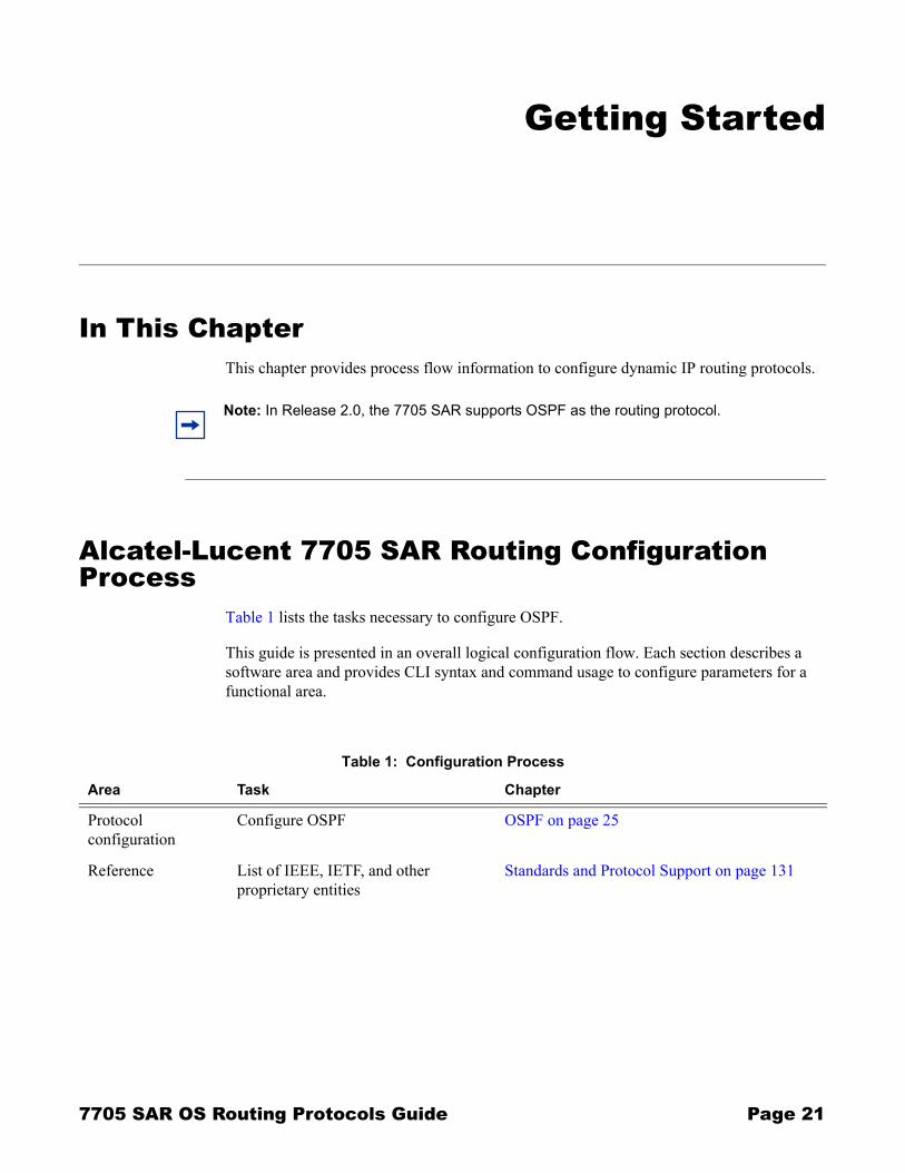
Table 1 lists the tasks necessary to configure OSPF.
This guide is presented in an overall logical configuration flow. Each section describes a software area and provides CLI syntax and command usage to configure parameters for a functional area.
Note: In Release 2.0, the 7705 SAR supports OSPF as the routing protocol.
Table 1: Configuration Process
Area Task Chapter
Protocol configuration
Configure OSPF OSPF on page 25
Reference List of IEEE, IETF, and other proprietary entities
Standards and Protocol Support on page 131
7705 SAR OS Routing Protocols Guide Page 21
Getting Started
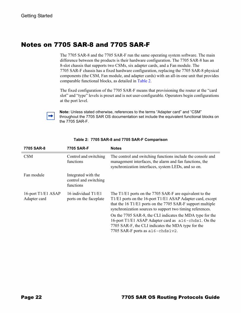
Notes on 7705 SAR-8 and 7705 SAR-FThe 7705 SAR-8 and the 7705 SAR-F run the same operating system software. The main difference between the products is their hardware configuration. The 7705 SAR-8 has an 8-slot chassis that supports two CSMs, six adapter cards, and a Fan module. The 7705 SAR-F chassis has a fixed hardware configuration, replacing the 7705 SAR-8 physical components (the CSM, Fan module, and adapter cards) with an all-in-one unit that provides comparable functional blocks, as detailed in Table 2.
The fixed configuration of the 7705 SAR-F means that provisioning the router at the �card slot� and �type� levels is preset and is not user-configurable. Operators begin configurations at the port level.
Note: Unless stated otherwise, references to the terms �Adapter card� and �CSM� throughout the 7705 SAR OS documentation set include the equivalent functional blocks on the 7705 SAR-F.
Table 2: 7705 SAR-8 and 7705 SAR-F Comparison
7705 SAR-8 7705 SAR-F Notes
CSM Control and switching functions
The control and switching functions include the console and management interfaces, the alarm and fan functions, the synchronization interfaces, system LEDs, and so on.
Fan module Integrated with the control and switching functions
16-port T1/E1 ASAP Adapter card
16 individual T1/E1 ports on the faceplate
The T1/E1 ports on the 7705 SAR-F are equivalent to the T1/E1 ports on the 16-port T1/E1 ASAP Adapter card, except that the 16 T1/E1 ports on the 7705 SAR-F support multiple synchronization sources to support two timing references.On the 7705 SAR-8, the CLI indicates the MDA type for the 16-port T1/E1 ASAP Adapter card as a16-chds1. On the 7705 SAR-F, the CLI indicates the MDA type for the 7705 SAR-F ports as a16-chds1v2.
Page 22 7705 SAR OS Routing Protocols Guide
Getting Started
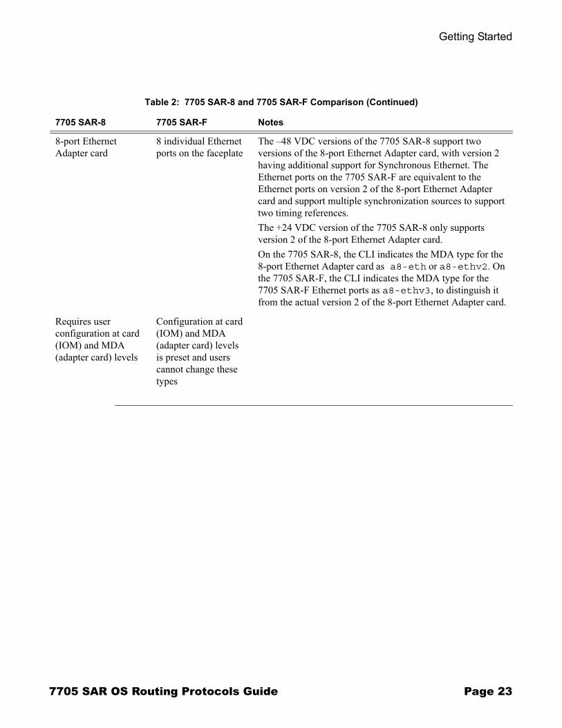
8-port Ethernet Adapter card
8 individual Ethernet ports on the faceplate
The �48 VDC versions of the 7705 SAR-8 support two versions of the 8-port Ethernet Adapter card, with version 2 having additional support for Synchronous Ethernet. The Ethernet ports on the 7705 SAR-F are equivalent to the Ethernet ports on version 2 of the 8-port Ethernet Adapter card and support multiple synchronization sources to support two timing references.The +24 VDC version of the 7705 SAR-8 only supports version 2 of the 8-port Ethernet Adapter card.On the 7705 SAR-8, the CLI indicates the MDA type for the 8-port Ethernet Adapter card as a8-eth or a8-ethv2. On the 7705 SAR-F, the CLI indicates the MDA type for the 7705 SAR-F Ethernet ports as a8-ethv3, to distinguish it from the actual version 2 of the 8-port Ethernet Adapter card.
Requires user configuration at card (IOM) and MDA (adapter card) levels
Configuration at card (IOM) and MDA (adapter card) levels is preset and users cannot change these types
Table 2: 7705 SAR-8 and 7705 SAR-F Comparison (Continued)
7705 SAR-8 7705 SAR-F Notes
7705 SAR OS Routing Protocols Guide Page 23

Getting Started
Page 24 7705 SAR OS Routing Protocols Guide
OSPF
In This ChapterThis chapter provides information about configuring the Open Shortest Path First (OSPF) protocol.
Topics in this chapter include:
� Overview of OSPF on page 26→ OSPF Areas on page 27
- Backbone Area on page 28- Stub Area on page 29- Not-So-Stubby Area on page 30
→ Virtual Links on page 30→ Neighbors and Adjacencies on page 31
- Designated Routers and Backup Designated Routers on page 31→ Link-State Advertisements on page 32→ Metrics on page 33→ Authentication on page 34→ Route Redistribution and Summarization on page 34→ OSPF-TE Extensions on page 35→ IP Subnets on page 35→ OSPF Instances on page 35→ Bidirectional Forwarding Detection (BFD) for OSPF on page 36→ Preconfiguration Requirements on page 36
� OSPF Configuration Process Overview on page 37� Configuration Notes on page 38� Configuring OSPF with CLI on page 39� OSPF Command Reference on page 57
7705 SAR OS Routing Protocols Guide Page 25
Overview of OSPF
Overview of OSPFIn Release 2.0 of the 7705 SAR, the router has the capability of functioning as an LSR (label switch router), allowing it to be used in more complex networks, for example:
� tier-2 aggregation (aggregator of aggregator sites) � traffic is aggregated from other tier-3 7705 SAR nodes (aggregated small cell sites) and this traffic along with local traffic is switched to tier-1 SR nodes
� ring-based configurations � multiple tier-3/tier-2 7705 SAR nodes are linked via a ring and an SR tier-2/tier-1 node, which acts as a gateway from the ring to a higher level or directly to the MTSO
The 7705 SAR must therefore support IP forwarding, in order to be able to switch traffic from one router to another in the network. To support these larger and more complex topologies, dynamic routing protocols are introduced. In this release, the 7705 SAR supports OSPF-TE as the routing protocol. OSFP-TE is used to advertise reachability information and traffic engineering information such as bandwidth.
In Release 2.0, the following major OSPF features are supported:
� areas � backbone, stub, and not-so-stubby areas (NSSAs)� virtual links� neighbors and adjacencies� link-state advertisements (LSAs)� metrics� authentication� route redistribution and summarization� OSPF traffic engineering (TE) extensions (to track and advertise available
bandwidth � used by MPLS traffic engineering; that is, RSVP-TE)
OSPF (Open Shortest Path First) is an interior gateway protocol (IGP) that is used within large autonomous systems (ASs). An autonomous system is a group of networks and network equipment under a common administration. OSPF is a link-state protocol; each router maintains an identical database (called the link-state database, topological database, or routing information database [RIB]) of the AS, including information about the local state of each router (for example, its usable interfaces and reachable neighbors). OSPF routers exchange status, cost, and other relevant interface information with neighboring routers. The information exchange enables all participating routers to establish their link-state database.
Note: For information on the 7705 SAR as an LSR, refer to the 7705 SAR OS MPLS Guide.
Page 26 7705 SAR OS Routing Protocols Guide
OSPF
OSPF uses a cost metric that represents the status of the link and the bandwidth of the interface in an algorithm to determine the best route to a destination. The algorithm used is called the SPF (shortest path first) or Dijkstra algorithm. Path selection is based on lowest cost, which might not necessarily be the shortest route but is the best route in regards to bandwidth. Each router applies the algorithm to calculate the shortest path to each destination in the network.
When the best route to a particular destination is determined, the route information is sent to the routing table manager (RTM). The RTM may contain more than one best route to a destination from multiple protocols. Because metrics from different protocols are not comparable, the RTM uses preference to select the best route. The route with the lowest preference value is selected. For more information, see Configuring Route Preferences on page 52.
The best routes from the RTM are then added to the forwarding table (also known as the forwarding database [or FIB]). All forwarding decisions are based on the information in the forwarding database.
The forwarding (or dropping) of packets is controlled by filters applied to the interface and route policies applied to the OSPF protocol. Refer to the 7705 SAR OS Router Configuration Guide for information on filters and route policies.
Alcatel-Lucent�s implementation of OSPF conforms to OSPF Version 2 specifications presented in RFC 2328, OSPF Version 2. Routers running OSPF can be enabled with minimal configuration. All default and command parameters can be modified.
OSPF AreasAn autonomous system can be divided into areas, with each area containing a group of networks. An area�s topology is concealed from the rest of the AS, which significantly reduces OSPF protocol traffic (LSA updates), simplifies the network topology, and simplifies the routing table by populating it with summarized routes rather than exact routes on each router. This decrease in LSA updates, link-state database size, and CPU time, all required for OSPF route calculations, results in a decrease in route calculation time.
All routers in an area have identical link-state databases for that area.
Areas within the same AS are linked to each other via area border routers (ABRs). An ABR is a router that belongs to more than one area. An ABR maintains a separate topological database for each area it is connected to.
7705 SAR OS Routing Protocols Guide Page 27
Overview of OSPF
Routing in the AS takes place on two levels, depending on whether the source and destination of a packet reside in the same area (intra-area routing) or different areas (inter-area routing). In intra-area routing, the packet is routed solely on information obtained within the area; that is, routing updates are only passed within the area. In inter-area routing, routing updates are passed between areas.
External routes refer to routing updates passed from another routing protocol into the OSPF domain.
Routers that pass information between an OSPF routing domain and a non-OSPF network are called autonomous system boundary routers (ASBRs).
Backbone Area
Every OSPF system requires a backbone area. The OSPF backbone area is uniquely identified as area 0 and uses the area ID 0.0.0.0. All other areas must be connected to the backbone area, either physically or logically. The backbone distributes routing information between areas. If it is not practical or possible to connect an area to the backbone (see area 0.0.0.5 in Figure 1), the ABRs (routers Y and Z in the figure) must be connected via a virtual link. The two ABRs form a point-to-point-like adjacency across the transit area (area 0.0.0.4).
Page 28 7705 SAR OS Routing Protocols Guide

OSPF
Stub Area
A stub area is a designated area that does not allow external route advertisements and cannot contain ASBRs. Virtual links cannot pass through stub areas.
To route to external destinations, the ABR of the stub area advertises a single default route into the stub area (0.0.0.0). A default route is the network route used by a router when no other known route exists for a given IP packet�s destination address. All packets for destinations not known by the router�s routing table are sent to the default route and thus out to the network.
This feature reduces the size of the router�s database and reduces OSPF protocol traffic, memory usage, and CPU route calculation time.
In Figure 1, areas 0.0.0.1, 0.0.0.2 and 0.0.0.5 could be configured as stub areas.
Figure 1: Backbone Area
Area 0.0.0.1
Area 0.0.0.3
Another AS
Area 0.0.0.2
Area 0.0.0.4
Area 0.0.0.5
Area 0.0.0.0
OSPF domain
Z
Y
20105
7705 SAR OS Routing Protocols Guide Page 29

Overview of OSPF
Not-So-Stubby Area
Another OSPF area type is called a not-so-stubby area (NSSA). NSSAs are similar to stub areas except that limited importing of external routes is allowed. Only routes within the AS are advertised. External routes learned by OSPF routers in the NSSA area are advertised as type 7 LSAs (external route advertisements only within the NSSA area) and are translated by ABRs into type 5 external route advertisements for distribution into other areas of the OSPF domain.
For information on LSA types, see Link-State Advertisements.
An NSSA area cannot be designated as the transit area of a virtual link.
In Figure 1, area 0.0.0.3 could be configured as an NSSA area.
Virtual LinksThe backbone area in an OSPF AS must be contiguous and all other areas must be directly connected to the backbone area via an ABR. If it is not practical or possible to physically connect an area to the backbone, virtual links can be used to connect to the backbone through a non-backbone area.
A virtual link functions as a point-to-point link that passes through a transit area. Figure 1 depicts routers Y and Z as the start and end points of the virtual link while area 0.0.0.4 is the transit area. In order to configure virtual links, the router must be an ABR. Virtual links are identified by the router ID of the other endpoint, which is another ABR. These two endpoint routers must be attached to a common area, called the transit area. The area through which the virtual link passes must have full routing information.
Transit areas pass traffic from an area adjacent to the backbone or to another area. The traffic does not originate or terminate in the transit area. The transit area cannot be a stub area or an NSSA area.
Virtual links are part of the backbone and behave as if they were unnumbered point-to-point networks between the two routers. A virtual link uses the intra-area routing of its transit area to forward packets. Virtual links are brought up and down through the building of the shortest-path trees for the transit area.
Page 30 7705 SAR OS Routing Protocols Guide
OSPF
Neighbors and AdjacenciesA router uses the OSPF Hello protocol to discover neighbors. Neighbors are routers that interface to a common network. In a broadcast-supported topology, one router sends Hello packets to a multicast address and receives Hello packets in return. Unicast Hello packets are used in non-broadcast topologies.
The neighbors then attempt to form adjacencies by exchanging link-state information with the goal of having identical link-state databases. When the link-state databases of two neighbors are synchronized, they are considered to be adjacent.
Designated Routers and Backup Designated Routers
In multi-access broadcast networks, such as Ethernet networks, with at least two attached routers, a designated router and a backup designated router can be elected. The concept of a designated router was developed in order to avoid the formation of adjacencies between all attached routers. Without a designated router, the area would be flooded with LSAs � a router would send LSAs to all its adjacent neighbors, and each in turn would send LSAs to all their neighbors, and so on. This would create multiple copies of the same LSA on the same link.
The designated router reduces the number of adjacencies required because each router forms an adjacency only with the designated router and backup designated router. Only the designated router sends LSAs in multicast format to the rest of the network, reducing the amount of routing protocol traffic and the size of the link-state database. If the designated router fails, the backup designated router becomes active.
The designated router is automatically elected based on priority � the router with the highest priority becomes the designated router and the router with the second-highest priority becomes the backup. If two routers have the same priority, the one with the highest router ID wins.
A router with a priority set to 0 can never become a designated router.
After a designated router is elected, it begins sending Hello packets to all other attached routers in order to form adjacencies.
Note: In point-to-point networks, where a single pair of routers are connected, no designated or backup designated router is elected. An adjacency must be formed with the neighbor router.
Note: To significantly improve adjacency forming and network convergence, a network should be configured as point-to-point if only two routers are connected, even if the network is a broadcast media such as Ethernet.
7705 SAR OS Routing Protocols Guide Page 31
Overview of OSPF
Link-State AdvertisementsLink-state advertisements (LSAs) describe the state of a router or network, including router interfaces and adjacency states. Each LSA is flooded throughout an area. The collection of LSAs from all routers and networks form the protocol�s link-state (or topological) database.
The distribution of topology database updates takes place along adjacencies. A router sends LSAs to advertise its state according to the configured interval and when the router�s state changes. These packets include information about the router's adjacencies, which allows detection of non-operational routes.
When a router discovers a routing table change or detects a change in the network, link-state information is advertised to other routers to maintain identical routing tables. Router adjacencies are reflected in the contents of its link-state advertisements. The relationship between adjacencies and the link states allow the protocol to detect non-operating routers. Link-state advertisements flood the area. The flooding mechanism ensures that all routers in an area have the same topological database. The database consists of the collection of LSAs received from each router belonging to the area.
OSPF sends only the changed information, not the whole topology information or whole link-state database, when a change takes place. From the topological database, each router constructs a tree of shortest paths with itself as root (that is, runs the Dijkstra algorithm). OSPF distributes routing information between routers belonging to a single AS.
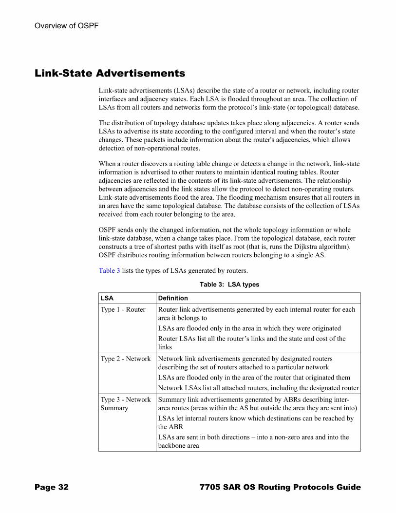
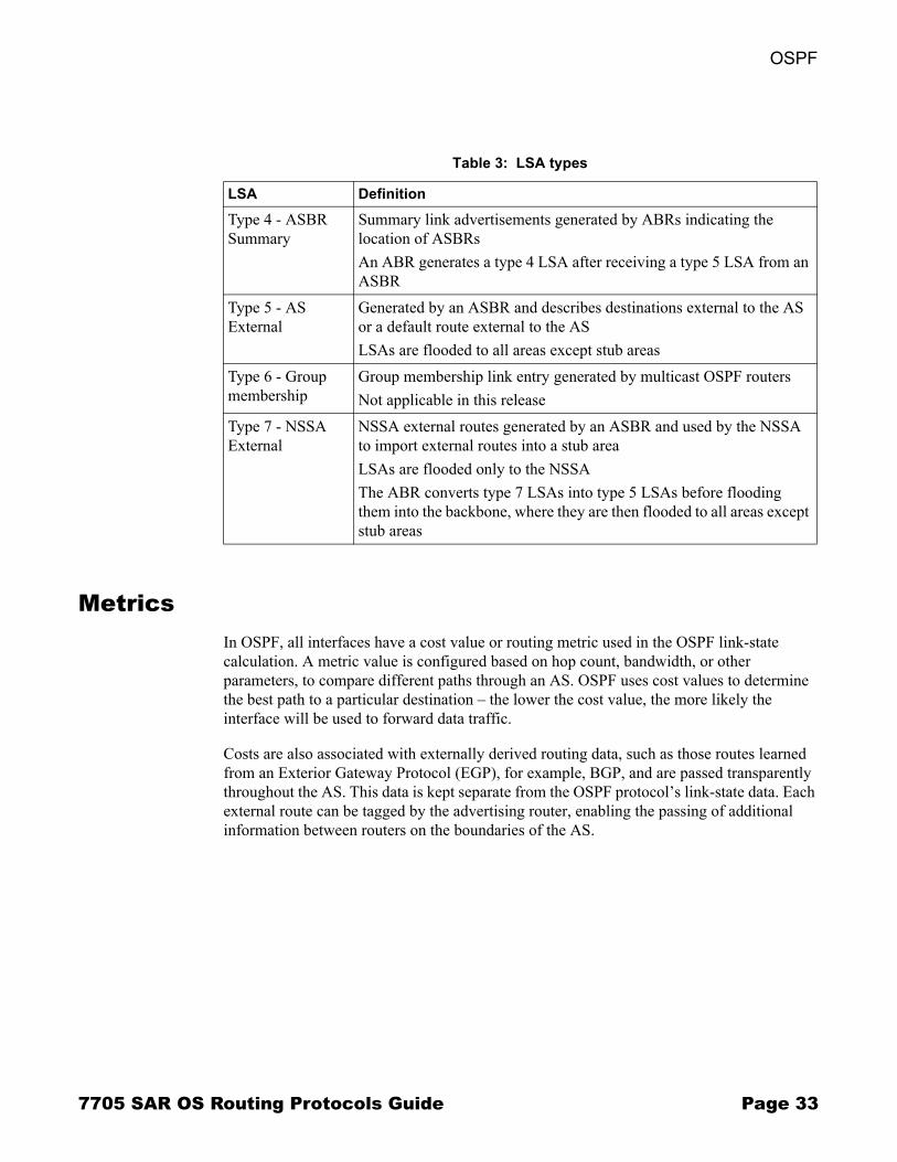
Table 3 lists the types of LSAs generated by routers.
Table 3: LSA types
LSA Definition
Type 1 - Router Router link advertisements generated by each internal router for each area it belongs toLSAs are flooded only in the area in which they were originatedRouter LSAs list all the router�s links and the state and cost of the links
Type 2 - Network Network link advertisements generated by designated routers describing the set of routers attached to a particular networkLSAs are flooded only in the area of the router that originated themNetwork LSAs list all attached routers, including the designated router
Type 3 - Network Summary
Summary link advertisements generated by ABRs describing inter-area routes (areas within the AS but outside the area they are sent into) LSAs let internal routers know which destinations can be reached by the ABRLSAs are sent in both directions � into a non-zero area and into the backbone area
Page 32 7705 SAR OS Routing Protocols Guide
OSPF
MetricsIn OSPF, all interfaces have a cost value or routing metric used in the OSPF link-state calculation. A metric value is configured based on hop count, bandwidth, or other parameters, to compare different paths through an AS. OSPF uses cost values to determine the best path to a particular destination � the lower the cost value, the more likely the interface will be used to forward data traffic.
Costs are also associated with externally derived routing data, such as those routes learned from an Exterior Gateway Protocol (EGP), for example, BGP, and are passed transparently throughout the AS. This data is kept separate from the OSPF protocol�s link-state data. Each external route can be tagged by the advertising router, enabling the passing of additional information between routers on the boundaries of the AS.
Type 4 - ASBR Summary
Summary link advertisements generated by ABRs indicating the location of ASBRsAn ABR generates a type 4 LSA after receiving a type 5 LSA from an ASBR
Type 5 - AS External
Generated by an ASBR and describes destinations external to the AS or a default route external to the ASLSAs are flooded to all areas except stub areas
Type 6 - Group membership
Group membership link entry generated by multicast OSPF routersNot applicable in this release
Type 7 - NSSA External
NSSA external routes generated by an ASBR and used by the NSSA to import external routes into a stub areaLSAs are flooded only to the NSSAThe ABR converts type 7 LSAs into type 5 LSAs before flooding them into the backbone, where they are then flooded to all areas except stub areas
Table 3: LSA types
LSA Definition
7705 SAR OS Routing Protocols Guide Page 33
Overview of OSPF
AuthenticationAll OSPF protocol exchanges can be authenticated. This guarantees that only trusted routers can participate in autonomous system routing. Alcatel-Lucent�s implementation of OSPF supports plain text (simple password) and Message Digest 5 (MD5) authentication.
When authentication is enabled on a link, a text string password must be configured. Neighbor OSPF routers must supply the password in all OSPF packets they send to an interface.
Plain text authentication includes the password in each OSPF packet sent on a link.
MD5 authentication is more secure than plain text authentication. MD5 authentication uses the password as an encryption key. Routers in the same routing domain must be configured with the same key. When the MD5 hashing algorithm is used for authentication, MD5 is used to verify data integrity by creating a 128-bit message digest from the data input that is included in each packet. The packet is transmitted to the router neighbor and can only be decrypted if the neighbor has the correct password.
By default, authentication is not enabled on an interface.
Route Redistribution and SummarizationRoute redistribution is the taking of routes from one protocol and sending them to another protocol. The 7705 SAR supports the redistribution of static routes into OSPF. These routes are advertised as type 5 or type 7 LSAs (external routes) and are included in each router�s link-state database.
Route redistribution involves the use of routing policies. For information on routing policies, refer to the 7705 SAR OS Router Configuration Guide.
Route summarization allows an ABR or ASBR to summarize routes with the same prefix into a single route and distribute it to other areas. Routes redistributed into OSPF from static routes can also be summarized.
Route summarization reduces the amount of routing information across areas and the size of routing tables on the routers, thus improving the calculation speed of the routers.
Page 34 7705 SAR OS Routing Protocols Guide
OSPF
OSPF-TE ExtensionsOSPF traffic engineering (TE) extensions enable the 7705 SAR to include traffic engineering information in the algorithm in order to calculate the best route to a destination. The traffic information includes:
� maximum reservable bandwidth� unreserved bandwidth� available bandwidth
IP SubnetsOSPF enables the flexible configuration of IP subnets. Each distributed OSPF route has a destination and mask. A network mask is a 32-bit number that indicates the range of IP addresses residing on a single IP network/subnet. This specification displays network masks as hexadecimal numbers; for example, the network mask for a class C IP network is displayed as 0xffffff00. This mask is often displayed as 255.255.255.0.
Two different subnets with the same IP network number might have different masks, called variable-length subnets. A packet is routed to the longest or most specific match. Host routes are considered to be subnets whose masks are all ones (0xffffffff).
For example, for a packet destined for IP address 10.1.1.1, 10.1.1.0/24 is a longer (better) match than 10.1.1.0/16. If both entries are in the routing table, the route designated by 10.1.1.0/24 will be used.
OSPF InstancesA routing instance is a routing entity for a router. In Release 2.0, the 7705 SAR supports the default routing instance only; it does not support multiple instances. The default routing instance is associated with the global routing table.
7705 SAR OS Routing Protocols Guide Page 35
Overview of OSPF
Bidirectional Forwarding Detection (BFD) for OSPFBFD is a simple protocol for detecting failures in a network. BFD uses a �hello� mechanism that sends control messages periodically to the far end and receives periodic control messages from the far end. BFD can detect device, link, and protocol failures.
When BFD is enabled on an OSPF interface, the state of the interface is tied to the state of the BFD session between the local node and remote (far-end) node. In Release 2.0, BFD is implemented in asynchronous mode only, meaning that neither end responds to control messages; rather, the messages are sent in the time period configured at each end.
If BFD control packets are not received in the configured amount of time, the link is declared down and OSPF takes the appropriate action (for example, generates an LSA update against the failed link or reroutes around the failed link).
Due to the lightweight nature of BFD, it can detect failures faster than other detection protocols, making it ideal for use in applications such as mobile transport.
Preconfiguration RequirementsThe router ID must be available before OSPF can be configured. The router ID is a 32-bit IP address assigned to each router running OSPF. This number uniquely identifies the router within an AS. OSPF routers use the router IDs of the neighbor routers to establish adjacencies. Neighbor IDs are learned when Hello packets are received from the neighbor.
Before configuring OSPF parameters, ensure that the router ID is derived by one of the following methods:
� define the value using the config>router router-id command� define the system interface using the config>router>interface
ip-int-name command (used if the router ID is not specified with the config>router router-id command)A system interface must have an IP address with a 32-bit subnet mask. The system interface is assigned during the primary router configuration process when the interface is created in the logical IP interface context.
� if you do not specify a router ID, the last 4 bytes of the MAC address are used
Page 36 7705 SAR OS Routing Protocols Guide

OSPF
OSPF Configuration Process OverviewFigure 2 displays the process to provision basic OSPF parameters.
Figure 2: OSPF Configuration Process
TURN UP
START
CONFIGURE THE ROUTER ID
DEFINE ONE OR MORE AREAS
DEFINE INTERFACES
DEFINE STUB AREA
DEFINE NSSA
CONFIGURE VIRTUAL LINKS
OPTIONAL
7705 SAR OS Routing Protocols Guide Page 37
Configuration Notes
Configuration Notes
General� Before OSPF can be configured, the router ID must be configured.� The basic OSPF configuration includes at least one area and an associated interface.� All default and command parameters can be modified. � By default, a router has no configured areas.� The base OSPF instance is created in the administratively enabled state.
Reference SourcesFor information on supported IETF drafts and standards, as well as standard and proprietary MIBs, refer to Standards and Protocol Support on page 131.
Page 38 7705 SAR OS Routing Protocols Guide
OSPF
Configuring OSPF with CLIThis section provides information to configure Open Shortest Path First (OSPF) using the command line interface.
Topics in this section include:
� OSPF Configuration Guidelines on page 40� Basic OSPF Configuration on page 41
→ Configuring the Router ID on page 41→ Configuring an OSPF Area on page 42→ Configuring an Interface on page 43
� Configuring Other OSPF Components on page 45→ Configuring a Stub Area on page 45→ Configuring a Not-So-Stubby Area on page 46→ Configuring a Virtual Link on page 46→ Configuring Authentication on page 48→ Assigning a Designated Router on page 50→ Configuring Route Summaries on page 51→ Configuring Route Preferences on page 52
� OSPF Configuration Management Tasks on page 54→ Modifying a Router ID on page 54→ Deleting a Router ID on page 55→ Modifying OSPF Parameters on page 55
7705 SAR OS Routing Protocols Guide Page 39

OSPF Configuration Guidelines
OSPF Configuration GuidelinesConfiguration planning is essential to organize routers, backbone, non-backbone, stub, NSSA areas, and transit links. OSPF provides essential defaults for basic protocol operability. You can configure or modify most commands and parameters.
The minimal OSPF parameters that are necessary to deploy OSPF are:
� router IDEach router running OSPF must be configured with a unique router ID. The router ID is used by the OSPF routing protocol to establish adjacencies.If a new router ID is defined, the OSPF protocol is not automatically restarted with the new ID. The router must be shut down and restarted in order to initialize the new router ID.
� area At least one OSPF area must be created. An interface must be assigned to each OSPF area.
� interfacesAn interface is the connection between a router and one of its attached networks. An interface has state information associated with it, which is obtained from the underlying lower-level protocols and the routing protocol. An interface to a network has associated with it a single IP address and mask (unless the network is an unnumbered point-to-point network). An interface is sometimes also referred to as a link.
Page 40 7705 SAR OS Routing Protocols Guide
OSPF
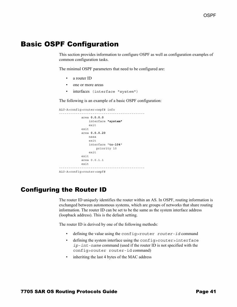
Basic OSPF ConfigurationThis section provides information to configure OSPF as well as configuration examples of common configuration tasks.
The minimal OSPF parameters that need to be configured are:
� a router ID� one or more areas� interfaces (interface "system")
The following is an example of a basic OSPF configuration:
ALU-A>config>router>ospf# info---------------------------------------------- area 0.0.0.0 interface "system" exit exit area 0.0.0.20 nssa exit interface "to-104" priority 10 exit exit area 0.0.1.1 exit----------------------------------------------ALU-A>config>router>ospf#
Configuring the Router IDThe router ID uniquely identifies the router within an AS. In OSPF, routing information is exchanged between autonomous systems, which are groups of networks that share routing information. The router ID can be set to be the same as the system interface address (loopback address). This is the default setting.
The router ID is derived by one of the following methods:
� defining the value using the config>router router-id command� defining the system interface using the config>router>interface
ip-int-name command (used if the router ID is not specified with the config>router router-id command)
� inheriting the last 4 bytes of the MAC address
7705 SAR OS Routing Protocols Guide Page 41

Basic OSPF Configuration
When configuring a new router ID, protocols are not automatically restarted with the new router ID. The next time a protocol is initialized, the new router ID is used. To force the new router ID, issue the shutdown and no shutdown commands for OSPF or restart the entire router.
Use the following CLI syntax to configure a router ID (in the config>router context):
CLI Syntax: router-id ip-address
The following displays a router ID configuration example:
A:ALU-B>config>router# info#------------------------------------------# IP Configuration#------------------------------------------ interface "system" address 10.10.10.104/32 exit interface "to-103" address 10.0.0.104/24 port 1/1/1 exit router-id 10.10.10.104...#------------------------------------------A:ALU-B>config>router#
Configuring an OSPF AreaAn OSPF area consists of routers configured with the same area ID. To include a router in a specific area, the common area ID must be assigned and an interface identified.
If your network consists of multiple areas, you must also configure a backbone area (0.0.0.0) on at least one router. The backbone contains the area border routers and other routers not included in other areas. The backbone distributes routing information between areas. To maintain backbone connectivity, there must be at least one interface in the backbone area or a virtual link must be configured to another router in the backbone area.
The minimal configuration must include an area ID and an interface. Modifying other command parameters is optional.
Use the following CLI syntax to configure an OSPF area (in the config>router context):
CLI Syntax: ospfarea area-id
area-range ip-prefix/mask [advertise|not-advertise]
blackhole-aggregate
Page 42 7705 SAR OS Routing Protocols Guide

OSPF
The following displays an OSPF area configuration example:
A:ALU-A>config>router>ospf# info---------------------------------------------- area 0.0.0.0 exit area 0.0.0.20 exit----------------------------------------------ALU-A>config>router>ospf#
Configuring an InterfaceIn OSPF, an interface can be configured to act as a connection between a router and one of its attached networks. An interface includes state information that was obtained from underlying lower-level protocols and from the routing protocol itself. An interface to a network is associated with a single IP address and mask (unless the network is an unnumbered point-to-point network). Note that if the address is removed from an interface, all OSPF data for the interface is also removed. If the address is merely changed, the OSPF configuration is preserved.
The passive command enables the passive property to and from the OSPF interface where passive interfaces are advertised as OSPF interfaces but do not run the OSPF protocol. By default, only interface addresses that are configured for OSPF are advertised as OSPF interfaces. The passive parameter allows an interface to be advertised as an OSPF interface without running the OSPF protocol. When enabled, the interface will ignore ingress OSPF protocol packets and not transmit any OSPF protocol packets.
Use the following CLI syntax to configure an OSPF interface (in the config>router context):
CLI Syntax: ospf area area-id
interface ip-int-nameadvertise-subnetauthentication-key [authentication-key|hash-key] [hash|hash2]authentication-type [password|message-digest]bfd-enable [remain-down-on-failure]dead-interval secondshello-interval secondsinterface-type {broadcast|point-to-point}message-digest-key key-id md5 [key|hash-key] [hash|hash2]metric metricmtu bytespassive
7705 SAR OS Routing Protocols Guide Page 43

Basic OSPF Configuration
priority numberretransmit-interval secondsno shutdowntransit-delay seconds
The following displays an interface configuration example:
A:ALU-49>config>router>ospf# info---------------------------------------------- asbr overload overload-on-boot timeout 60 traffic-engineering export "OSPF-Export" exit area 0.0.0.0 virtual-link 1.2.3.4 transit-area 1.2.3.4 hello-interval 9 dead-interval 40 exit interface "system" exit exit area 0.0.0.20 stub exit interface "to-103" exit exit area 0.0.0.25 nssa exit exit area 1.2.3.4 exit----------------------------------------------A:ALU-49>config>router>ospf#
Page 44 7705 SAR OS Routing Protocols Guide
OSPF
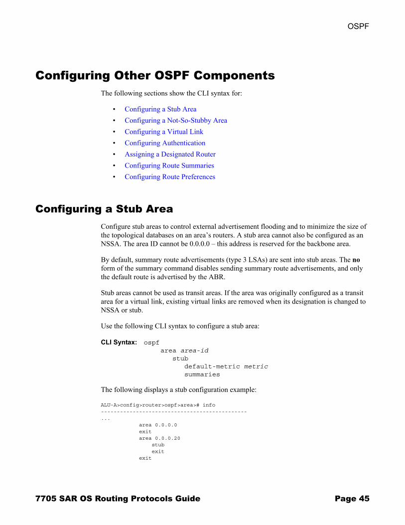
Configuring Other OSPF ComponentsThe following sections show the CLI syntax for:
� Configuring a Stub Area� Configuring a Not-So-Stubby Area� Configuring a Virtual Link� Configuring Authentication� Assigning a Designated Router� Configuring Route Summaries� Configuring Route Preferences
Configuring a Stub AreaConfigure stub areas to control external advertisement flooding and to minimize the size of the topological databases on an area�s routers. A stub area cannot also be configured as an NSSA. The area ID cannot be 0.0.0.0 � this address is reserved for the backbone area.
By default, summary route advertisements (type 3 LSAs) are sent into stub areas. The no form of the summary command disables sending summary route advertisements, and only the default route is advertised by the ABR.
Stub areas cannot be used as transit areas. If the area was originally configured as a transit area for a virtual link, existing virtual links are removed when its designation is changed to NSSA or stub.
Use the following CLI syntax to configure a stub area:
CLI Syntax: ospfarea area-id
stubdefault-metric metricsummaries
The following displays a stub configuration example:
ALU-A>config>router>ospf>area># info----------------------------------------------... area 0.0.0.0 exit area 0.0.0.20 stub exit exit
7705 SAR OS Routing Protocols Guide Page 45
Configuring Other OSPF Components
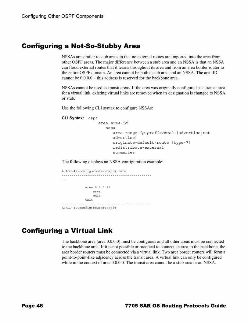
Configuring a Not-So-Stubby AreaNSSAs are similar to stub areas in that no external routes are imported into the area from other OSPF areas. The major difference between a stub area and an NSSA is that an NSSA can flood external routes that it learns throughout its area and from an area border router to the entire OSPF domain. An area cannot be both a stub area and an NSSA. The area ID cannot be 0.0.0.0 � this address is reserved for the backbone area.
NSSAs cannot be used as transit areas. If the area was originally configured as a transit area for a virtual link, existing virtual links are removed when its designation is changed to NSSA or stub.
Use the following CLI syntax to configure NSSAs:
CLI Syntax: ospf area area-id
nssaarea-range ip-prefix/mask [advertise|not-advertise]originate-default-route [type-7]redistribute-externalsummaries
The following displays an NSSA configuration example:
A:ALU-49>config>router>ospf# info---------------------------------------------- ...
area 0.0.0.25 nssa exit exit----------------------------------------------A:ALU-49>config>router>ospf#
Configuring a Virtual LinkThe backbone area (area 0.0.0.0) must be contiguous and all other areas must be connected to the backbone area. If it is not possible or practical to connect an area to the backbone, the area border routers must be connected via a virtual link. Two area border routers will form a point-to-point-like adjacency across the transit area. A virtual link can only be configured while in the context of area 0.0.0.0. The transit area cannot be a stub area or an NSSA.
Page 46 7705 SAR OS Routing Protocols Guide
OSPF
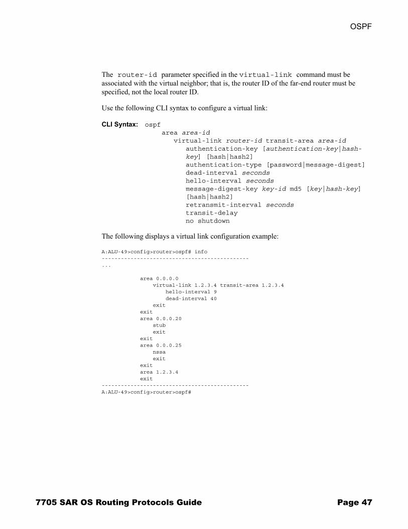
The router-id parameter specified in the virtual-link command must be associated with the virtual neighbor; that is, the router ID of the far-end router must be specified, not the local router ID.
Use the following CLI syntax to configure a virtual link:
CLI Syntax: ospfarea area-id
virtual-link router-id transit-area area-idauthentication-key [authentication-key|hash-key] [hash|hash2] authentication-type [password|message-digest]dead-interval secondshello-interval secondsmessage-digest-key key-id md5 [key|hash-key] [hash|hash2]retransmit-interval secondstransit-delayno shutdown
The following displays a virtual link configuration example:
A:ALU-49>config>router>ospf# info----------------------------------------------... area 0.0.0.0 virtual-link 1.2.3.4 transit-area 1.2.3.4 hello-interval 9 dead-interval 40 exit exit area 0.0.0.20 stub exit exit area 0.0.0.25 nssa exit exit area 1.2.3.4 exit----------------------------------------------A:ALU-49>config>router>ospf#
7705 SAR OS Routing Protocols Guide Page 47
Configuring Other OSPF Components
Configuring AuthenticationAuthentication must be explicitly configured. The following authentication commands can be configured on the interface level or the virtual link level:
� authentication-key � configures the password used by the OSPF interface or virtual link to send and receive OSPF protocol packets on the interface when simple password authentication is configured
� authentication-type � enables authentication and specifies the type of authentication to be used on the OSPF interface, either password or message digest
� message-digest-key � command used when the message-digest keyword is selected in the authentication-type command. The Message Digest 5 (MD5) hashing algorithm is used for authentication. MD5 is used to verify data integrity by creating a 128-bit message digest from the data input. It is unique to that specific data.
A special checksum is included in transmitted packets and is used by the far-end router to verify the packet by using an authentication key (a password). Routers on both ends must use the same authentication key.
MD5 can be configured on each interface and each virtual link. If MD5 is enabled on an interface, that interface accepts routing updates only if the MD5 authentication is accepted. Updates that are not authenticated are rejected. A router accepts only OSPF packets sent with the same key-id value defined for the interface.
If the hash parameter is not used in the authentication commands, unencrypted characters can be entered. If the hash parameter is used, all keys specified in the command are stored in encrypted format in the configuration file. When the hash keyword is specified, the password must be entered in encrypted form. Hashing cannot be reversed. To configure an unhashed key, issue the no message-digest-key key-id command and then re-enter the command without the hash parameter.
Page 48 7705 SAR OS Routing Protocols Guide
OSPF
Use the following CLI syntax to configure authentication:
CLI Syntax: ospf area area-id
interface ip-int-nameauthentication-key [authentication-key|hash-key] [hash|hash2]authentication-type [password|message-digest]message-digest-key key-id md5 [key|hash-key] [hash|hash2]
virtual-link router-id transit-area area-idauthentication-key [authentication-key|hash-key] [hash|hash2]authentication-type [password|message-digest]message-digest-key key-id md5 [key|hash-key] [hash|hash2]
The following displays authentication configuration examples:
A:ALU-49>config>router>ospf# info----------------------------------------------... area 0.0.0.40 interface "test1" authentication-type password authentication-key "3WErEDozxyQ" hash exit exit area 1.2.3.4 exit----------------------------------------------A:ALU-49>config>router>ospf#
A:ALU-49>config>router>ospf# info----------------------------------------------... area 0.0.0.0 virtual-link 10.0.0.1 transit-area 0.0.0.1 authentication-type message-digest message-digest-key 2 md5 "Mi6BQAFi3MI" hash exit virtual-link 1.2.3.4 transit-area 1.2.3.4 hello-interval 9 dead-interval 40 exit interface "system" exit exit----------------------------------------------A:ALU-49>config>router>ospf#
7705 SAR OS Routing Protocols Guide Page 49
Configuring Other OSPF Components
Assigning a Designated RouterThe designated router is responsible for flooding network link advertisements on a broadcast network to describe the routers attached to the network. A router uses Hello packets to advertise its priority. The router with the highest-priority interface becomes the designated router. If routers have the same priority, the designated router is elected based on the highest router ID. A router with priority 0 is not eligible to be a designated router or a backup designated router. At least one router on each logical IP network or subnet must be eligible to be the designated router. By default, routers have a priority value of 1.
When a router starts up, it checks for a current designated router. If a designated router is present, the router accepts that designated router, regardless of its own priority designation. If the designated and backup designated routers fail, new designated and backup routers are elected according to their priority numbers or router IDs (in case of a priority tie).
Designated routers are used only in multi-access (broadcast) networks.
Use the following CLI syntax to configure the designated router:
CLI Syntax: ospf area area-id
interface ip-int-namepriority number
The following displays a priority designation example:
A:ALU-49>config>router>ospf# info----------------------------------------------... area 0.0.0.25 nssa exit interface "if2" priority 100 exit exit----------------------------------------------A:ALU-49>config>router>ospf#
Page 50 7705 SAR OS Routing Protocols Guide
OSPF
Configuring Route SummariesABRs send summary advertisements (type 3 LSAs) into a stub area or NSSA to describe the routes to other areas. This command is particularly useful in order to reduce the size of the link-state database within the stub or NSSA.
By default, summary route advertisements are sent into the stub area or NSSA. The no form of the summaries command disables sending summary route advertisements and, in stub areas, the default route is advertised by the area border router.
Use the following CLI syntax to configure a route summary:
CLI Syntax: ospfarea area-id
stubsummaries
nssasummaries
The following displays a stub route summary configuration example:
A:ALU-49>config>router>ospf# info----------------------------------------------... area 0.0.0.20 stub summaries exit interface "to-103" exit exit----------------------------------------------A:ALU-49>config>router>ospf#
7705 SAR OS Routing Protocols Guide Page 51
Configuring Other OSPF Components
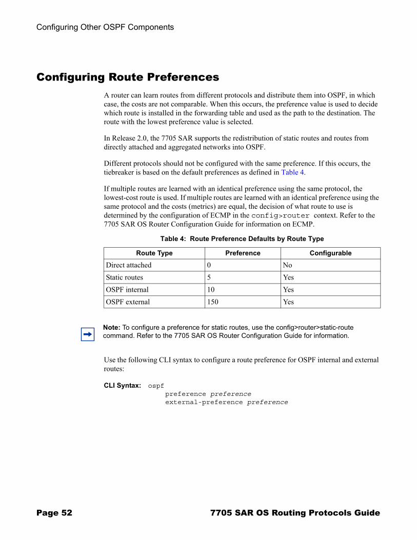
Configuring Route PreferencesA router can learn routes from different protocols and distribute them into OSPF, in which case, the costs are not comparable. When this occurs, the preference value is used to decide which route is installed in the forwarding table and used as the path to the destination. The route with the lowest preference value is selected.
In Release 2.0, the 7705 SAR supports the redistribution of static routes and routes from directly attached and aggregated networks into OSPF.
Different protocols should not be configured with the same preference. If this occurs, the tiebreaker is based on the default preferences as defined in Table 4.
If multiple routes are learned with an identical preference using the same protocol, the lowest-cost route is used. If multiple routes are learned with an identical preference using the same protocol and the costs (metrics) are equal, the decision of what route to use is determined by the configuration of ECMP in the config>router context. Refer to the 7705 SAR OS Router Configuration Guide for information on ECMP.
Use the following CLI syntax to configure a route preference for OSPF internal and external routes:
CLI Syntax: ospfpreference preferenceexternal-preference preference
Table 4: Route Preference Defaults by Route Type
Route Type Preference Configurable
Direct attached 0 NoStatic routes 5 YesOSPF internal 10 YesOSPF external 150 Yes
Note: To configure a preference for static routes, use the config>router>static-route command. Refer to the 7705 SAR OS Router Configuration Guide for information.
Page 52 7705 SAR OS Routing Protocols Guide
OSPF
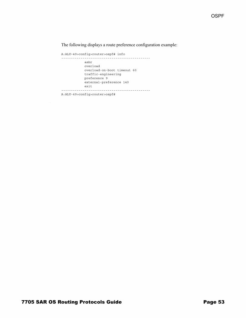
The following displays a route preference configuration example:
A:ALU-49>config>router>ospf# info---------------------------------------------- asbr overload overload-on-boot timeout 60 traffic-engineering preference 9 external-preference 140 exit----------------------------------------------A:ALU-49>config>router>ospf#
7705 SAR OS Routing Protocols Guide Page 53

OSPF Configuration Management Tasks
OSPF Configuration Management TasksThis section discusses the following OSPF configuration management tasks:
� Modifying a Router ID� Deleting a Router ID� Modifying OSPF Parameters
Modifying a Router ID Because the router ID is defined in the config>router context, not in the OSPF configuration context, the protocol instance is not aware of changes to the ID value. Changing the router ID on a device could cause configuration inconsistencies if associated values are not also modified.
After you have changed a router ID, manually shut down and restart the protocol using the shutdown and no shutdown commands in order for the changes to be incorporated.
Use the following CLI syntax to change a router ID number:
CLI Syntax:config>router# router-id router-id
The following displays an NSSA router ID modification example:
A:ALU-49>config>router# info------------------------------------------IP Configuration------------------------------------------ interface "system" address 10.10.10.104/32 exit interface "to-103" address 10.0.0.103/24 port 1/1/1 exit router-id 10.10.10.104------------------------------------------A:ALU-49>config>router#
Page 54 7705 SAR OS Routing Protocols Guide

OSPF
Deleting a Router IDYou can modify a router ID, but you cannot delete the parameter. If the no router router-id command is issued, the router ID reverts to the default value, the system interface address (which is also the loopback address). If a system interface address is not configured, the last 4 bytes of the chassis MAC address are used as the router ID.
Modifying OSPF Parameters You can change or remove existing OSPF parameters in the CLI. The changes are applied immediately.
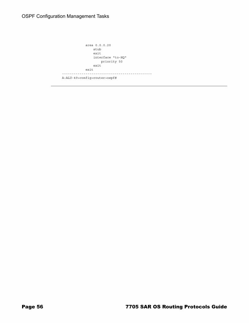
The following example displays an OSPF modification in which an interface is removed and another interface added.
Example: config>router# ospf
config>router>ospf# area 0.0.0.20config>router>ospf>area# no interface "to-103"config>router>ospf>area# interface "to-HQ"config>router>ospf>area>if$ priority 50config>router>ospf>area>if# exitconfig>router>ospf>area# exit
The following example displays the OSPF configuration with the modifications entered in the previous example:
A:ALU-49>config>router>ospf# info---------------------------------------------- asbr overload overload-on-boot timeout 60 traffic-engineering preference 9 external-preference 140 export "OSPF-Export" exit area 0.0.0.0 virtual-link 10.0.0.1 transit-area 0.0.0.1 authentication-type message-digest message-digest-key 2 md5 "Mi6BQAFi3MI" hash exit virtual-link 1.2.3.4 transit-area 1.2.3.4 hello-interval 9 dead-interval 40 exit interface "system" exit exit area 0.0.0.1 exit
7705 SAR OS Routing Protocols Guide Page 55
OSPF Configuration Management Tasks
area 0.0.0.20 stub exit interface "to-HQ" priority 50 exit exit----------------------------------------------A:ALU-49>config>router>ospf#
Page 56 7705 SAR OS Routing Protocols Guide
OSPF
OSPF Command Reference
Command Hierarchies� Configuration Commands� Show Commands� Clear Commands� Debug Commands� Tools Commands (refer to the Tools chapter in the 7705 SAR OS Services Guide)
7705 SAR OS Routing Protocols Guide Page 57
OSPF Command Reference
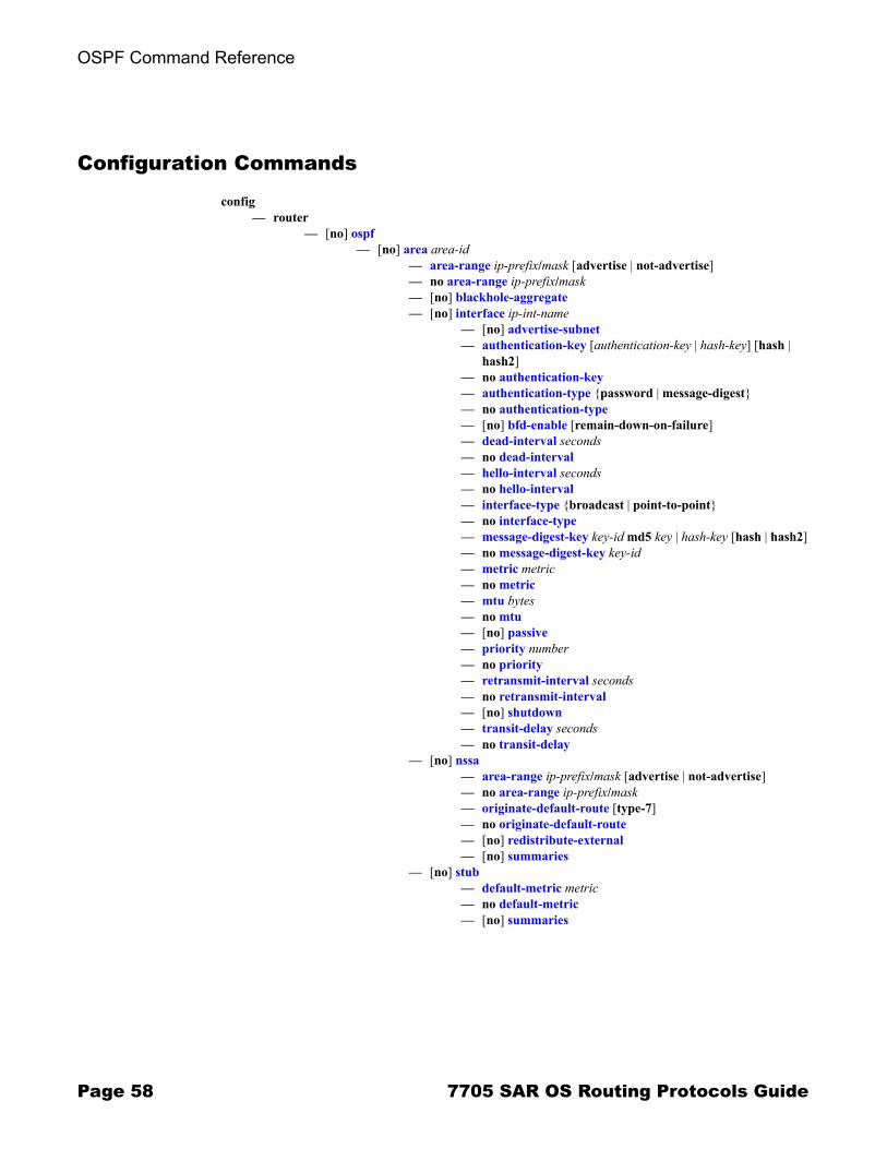
Configuration Commands
config� router
� [no] ospf � [no] area area-id
� area-range ip-prefix/mask [advertise | not-advertise]� no area-range ip-prefix/mask� [no] blackhole-aggregate� [no] interface ip-int-name
� [no] advertise-subnet� authentication-key [authentication-key | hash-key] [hash |
hash2]� no authentication-key� authentication-type {password | message-digest}� no authentication-type� [no] bfd-enable [remain-down-on-failure]� dead-interval seconds� no dead-interval� hello-interval seconds� no hello-interval� interface-type {broadcast | point-to-point}� no interface-type� message-digest-key key-id md5 key | hash-key [hash | hash2]� no message-digest-key key-id� metric metric� no metric� mtu bytes� no mtu� [no] passive� priority number� no priority� retransmit-interval seconds� no retransmit-interval� [no] shutdown� transit-delay seconds� no transit-delay
� [no] nssa� area-range ip-prefix/mask [advertise | not-advertise]� no area-range ip-prefix/mask� originate-default-route [type-7]� no originate-default-route � [no] redistribute-external� [no] summaries
� [no] stub� default-metric metric� no default-metric� [no] summaries
Page 58 7705 SAR OS Routing Protocols Guide
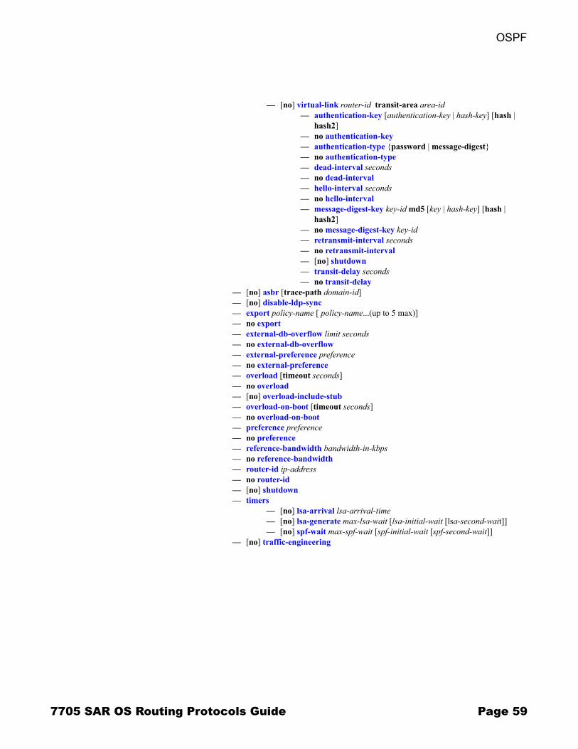
OSPF
� [no] virtual-link router-id transit-area area-id� authentication-key [authentication-key | hash-key] [hash |
hash2]� no authentication-key� authentication-type {password | message-digest}� no authentication-type� dead-interval seconds� no dead-interval� hello-interval seconds� no hello-interval� message-digest-key key-id md5 [key | hash-key] [hash |
hash2]� no message-digest-key key-id� retransmit-interval seconds� no retransmit-interval� [no] shutdown� transit-delay seconds� no transit-delay
� [no] asbr [trace-path domain-id]� [no] disable-ldp-sync� export policy-name [ policy-name...(up to 5 max)]� no export� external-db-overflow limit seconds� no external-db-overflow� external-preference preference� no external-preference� overload [timeout seconds]� no overload� [no] overload-include-stub� overload-on-boot [timeout seconds]� no overload-on-boot� preference preference� no preference� reference-bandwidth bandwidth-in-kbps� no reference-bandwidth� router-id ip-address� no router-id� [no] shutdown� timers
� [no] lsa-arrival lsa-arrival-time� [no] lsa-generate max-lsa-wait [lsa-initial-wait [lsa-second-wait]]� [no] spf-wait max-spf-wait [spf-initial-wait [spf-second-wait]]
� [no] traffic-engineering
7705 SAR OS Routing Protocols Guide Page 59
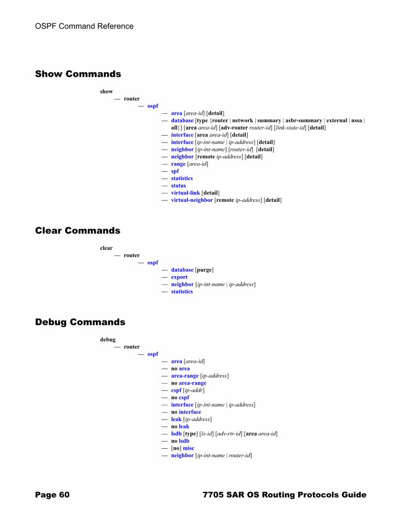
OSPF Command Reference
Show Commands
show� router
� ospf � area [area-id] [detail]� database [type {router | network | summary | asbr-summary | external | nssa |
all}] [area area-id] [adv-router router-id] [link-state-id] [detail]� interface [area area-id] [detail]� interface [ip-int-name | ip-address] [detail]� neighbor [ip-int-name] [router-id] [detail]� neighbor [remote ip-address] [detail]� range [area-id]� spf� statistics� status� virtual-link [detail]� virtual-neighbor [remote ip-address] [detail]
Clear Commands
clear� router
� ospf � database [purge]� export� neighbor [ip-int-name | ip-address]� statistics
Debug Commands
debug� router
� ospf� area [area-id]� no area� area-range [ip-address]� no area-range� cspf [ip-addr]� no cspf� interface [ip-int-name | ip-address]� no interface� leak [ip-address]� no leak� lsdb [type] [ls-id] [adv-rtr-id] [area area-id]� no lsdb� [no] misc� neighbor [ip-int-name | router-id]
Page 60 7705 SAR OS Routing Protocols Guide
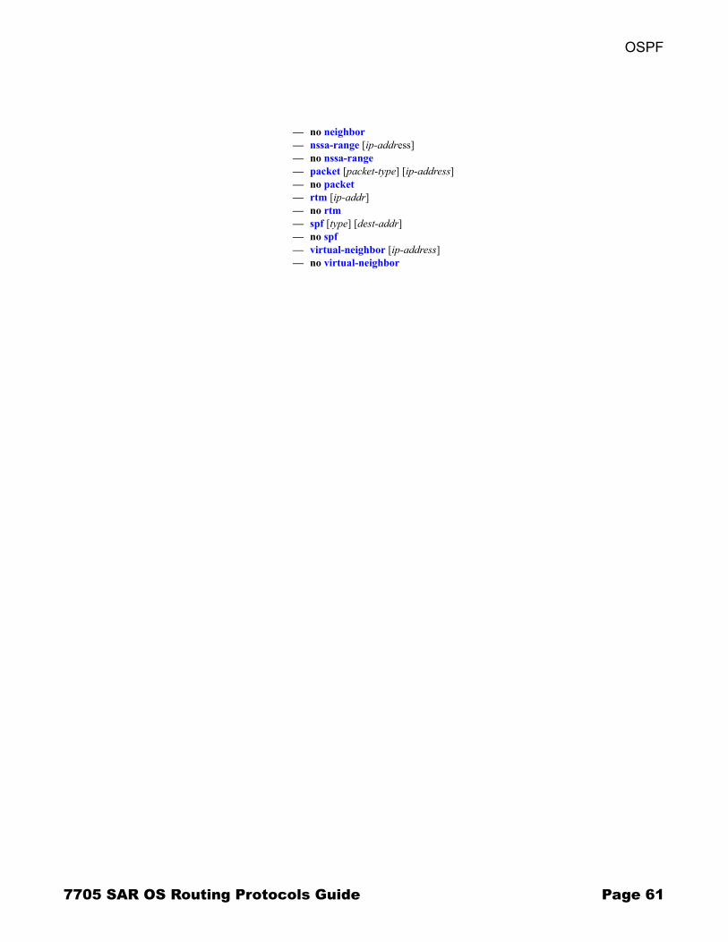
OSPF
� no neighbor� nssa-range [ip-address]� no nssa-range� packet [packet-type] [ip-address]� no packet� rtm [ip-addr]� no rtm� spf [type] [dest-addr]� no spf� virtual-neighbor [ip-address]� no virtual-neighbor
7705 SAR OS Routing Protocols Guide Page 61
OSPF Command Reference
Command Descriptions� Configuration Commands on page 63� Show Commands on page 90� Clear Commands on page 125� Debug Commands on page 127
Page 62 7705 SAR OS Routing Protocols Guide
OSPF
Configuration Commands
� Generic Commands on page 64� Global Commands on page 65� Area Commands on page 76� Interface/Virtual Link Commands on page 81
7705 SAR OS Routing Protocols Guide Page 63

OSPF Command Reference
Generic Commands
shutdown
Syntax [no] shutdown
Context config>router>ospfconfig>router>ospf>area>interface config>router>ospf>area>virtual-link
Description This command administratively disables the entity. When disabled, an entity does not change, reset, or remove any configuration settings or statistics. Many entities must be explicitly enabled using the no shutdown command.
The operational state of the entity is disabled as well as the operational state of any entities contained within. Many objects must be shut down before they can be deleted.
Unlike other commands and parameters where the default state is not indicated in the configuration file, shutdown and no shutdown are always indicated in system-generated configuration files.
The no form of the command puts an entity into the administratively enabled state.
Default OSPF Protocol � The Open Shortest Path First (OSPF) protocol is created in the no shutdown state.
OSPF Interface � When an IP interface is configured as an OSPF interface, OSPF on the interface is in the no shutdown state by default.
Page 64 7705 SAR OS Routing Protocols Guide
OSPF
Global Commands
ospf
Syntax [no] ospf
Context config>router
Description This command activates OSPF on the router and enables access to the context to define OSPF parameters.
Before OSPF can be activated on the router, the router ID must be configured.
The router ID uniquely identifies the router within an AS. In OSPF, routing information is exchanged between autonomous systems, which are groups of networks that share routing information. The router ID can be set to be the same as the system interface address (loopback address).
The router ID is derived by one of the following methods:
� defining the value using the config>router router-id command� defining the system interface using the config>router>interface
ip-int-name command (used if the router ID is not specified with the config>router router-id command)
� inheriting the last 4 bytes of the MAC address
When configuring a new router ID, protocols are not automatically restarted with the new router ID. The next time a protocol is initialized, the new router ID is used. To force the new router ID, issue the shutdown and no shutdown commands for OSPF or restart the entire router.
The no form of the command to reverts to the default value.
Default no ospf
7705 SAR OS Routing Protocols Guide Page 65

OSPF Command Reference
asbr
Syntax [no] asbr [trace-path domain-id]
Context config>router>ospf
Description This command configures the router as an Autonomous System Boundary Router (ASBR) if the router is to be used to distribute external routes into the OSPF domain. When a router is configured as an ASBR, the export policies into the OSPF domain take effect. If no policies are configured, no external routes are redistributed into the OSPF domain.
The no form of the command removes the ASBR status and withdraws the routes redistributed from the routing table into OSPF from the link-state database.
In Release 2.0, only the base OSPF instance is supported; therefore, the domain ID may not need to be configured. However, in order to prevent routing loops (where routes learned from one domain are redistributed back into the domain), the domain ID can be used to tag external LSAs � indicating which domain or network they have learned the route from.
Default no asbr � the router is not an ASBR
Parameters domain-id � specifies the domain ID
Values 1 to 31
Default 0x0
disable-ldp-sync
Syntax [no] disable-ldp-sync
Context config>router>ospf
Description This command disables the IGP-LDP synchronization feature on all interfaces participating in the OSPF routing protocol. When this command is executed, IGP immediately advertises the actual value of the link cost for all interfaces that have the IGP-LDP synchronization enabled if the currently advertised cost is different. IGP-LDP synchronization will then be disabled for all interfaces. This command does not delete the interface configuration.
The no form of this command restores the default settings and re-enables IGP-LDP synchronization on all interfaces participating in the OSPF routing protocol and for which the ldp-sync-timer is configured (refer to the 7705 SAR OS Router Configuration Guide for information on configuring the ldp-sync-timer).
Default no disable-ldp-sync
Page 66 7705 SAR OS Routing Protocols Guide
OSPF
export
Syntax export policy-name [policy-name�]no export
Context config>router>ospf
Description This command associates export route policies to determine which routes are exported from the route table to OSPF. Export polices are only in effect if OSPF is configured as an ASBR.
If no export policy is specified, non-OSPF routes are not exported from the routing table manager to OSPF.
If multiple policy names are specified, the policies are evaluated in the order they are specified. The first policy that matches is applied. If multiple export commands are issued, the last command entered will override the previous command. A maximum of five policy names can be specified.
The no form of the command removes all policies from the configuration.
Refer to the 7705 SAR OS Router Configuration Guide for information on defining route policies.
Default no export � no export route policies specified
Parameters policy-name � the export route policy name. Allowed values are any string up to 32 characters long composed of printable, 7-bit ASCII characters. If the string contains special characters (#, $, spaces, etc.), the entire string must be enclosed within double quotes.
The specified name(s) must already be defined.
external-db-overflow
Syntax external-db-overflow limit secondsno external-db-overflow
Context config>router>ospf
Description This command enables limits on the number of non-default, AS-external-LSA entries that can be stored in the link-state database (LSDB) and specifies a wait timer before processing these after the limit is exceeded.
The limit value specifies the maximum number of entries that can be stored in the LSDB. Placing a limit on these LSAs in the LSDB protects the router from receiving an excessive number of external routes that consume excessive memory or CPU resources. If the number of routes reaches or exceeds the limit, the table is in an overflow state. When in an overflow state, the router will not originate any new AS-external-LSAs and will withdraw all the self-originated non-default external LSAs.
The seconds value specifies the amount of time to wait after an overflow state before regenerating and processing non-default, AS-external-LSAs. The waiting period acts like a dampening period, preventing the router from continuously running shortest path first (SPF) calculations caused by the excessive number of non-default, AS-external LSAs.
7705 SAR OS Routing Protocols Guide Page 67
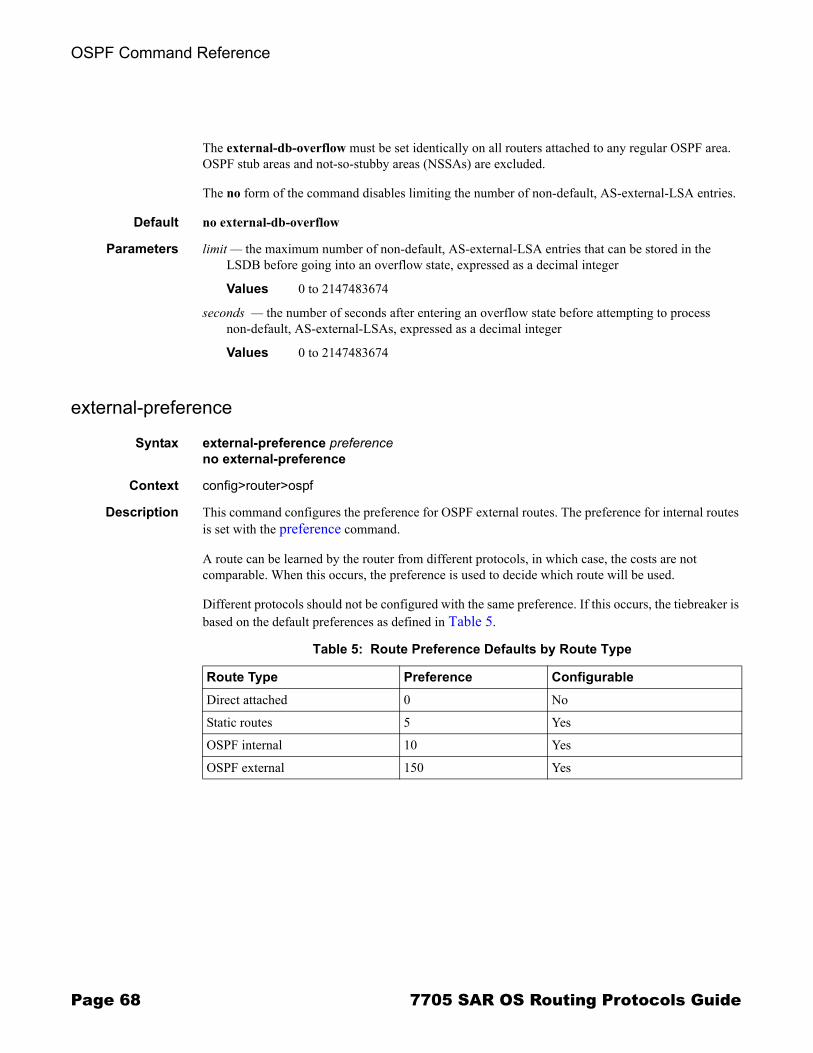
OSPF Command Reference
The external-db-overflow must be set identically on all routers attached to any regular OSPF area. OSPF stub areas and not-so-stubby areas (NSSAs) are excluded.
The no form of the command disables limiting the number of non-default, AS-external-LSA entries.
Default no external-db-overflow
Parameters limit � the maximum number of non-default, AS-external-LSA entries that can be stored in the LSDB before going into an overflow state, expressed as a decimal integer
Values 0 to 2147483674
seconds � the number of seconds after entering an overflow state before attempting to process non-default, AS-external-LSAs, expressed as a decimal integer
Values 0 to 2147483674
external-preference
Syntax external-preference preferenceno external-preference
Context config>router>ospf
Description This command configures the preference for OSPF external routes. The preference for internal routes is set with the preference command.
A route can be learned by the router from different protocols, in which case, the costs are not comparable. When this occurs, the preference is used to decide which route will be used.
Different protocols should not be configured with the same preference. If this occurs, the tiebreaker is based on the default preferences as defined in Table 5.
Table 5: Route Preference Defaults by Route Type
Route Type Preference ConfigurableDirect attached 0 No
Static routes 5 Yes
OSPF internal 10 Yes
OSPF external 150 Yes
Page 68 7705 SAR OS Routing Protocols Guide

OSPF
If multiple routes are learned with an identical preference using the same protocol, the lowest-cost route is used. If multiple routes are learned with an identical preference using the same protocol and the costs (metrics) are equal, the decision of what route to use is determined by the configuration of ECMP in the config>router context. Refer to the 7705 SAR OS Router Configuration Guide for information on ECMP.
The no form of the command reverts to the default value.
Default external-preference 150 � OSPF external routes have a default preference of 150
Parameters preference � the preference for external routes expressed as a decimal integer
Values 1 to 255
overload
Syntax overload [timeout seconds]no overload
Context config>router>ospf
Description This command changes the overload state of the local router so that it appears to be overloaded. When overload is enabled, the router can participate in OSPF routing, but is not used for transit traffic. Traffic destined for directly attached interfaces continues to reach the router.
To put the IGP in an overload state, enter a timeout value. The IGP will enter the overload state until the timeout timer expires or a no overload command is executed.
If the overload command is encountered during the execution of an overload-on-boot command, the overload command takes precedence. This could occur as a result of a saved configuration file where both parameters are saved. When the file is saved by the system, the overload-on-boot command is saved after the overload command.
Use the no form of this command to return to the default. When the no overload command is executed, the overload state is terminated regardless of the reason the protocol entered the overload state.
Default no overload
Parameters seconds � the number of seconds to reset overloading
Values 1 to 1800
Default 60
Note: To configure a preference for static routes, use the config>router>static-route command. Refer to the 7705 SAR OS Router Configuration Guide for information.
7705 SAR OS Routing Protocols Guide Page 69

OSPF Command Reference
overload-include-stub
Syntax [no] overload-include-stub
Context config>router>ospf
Description This command is used to determine if the OSPF stub networks should be advertised with a maximum metric value when the system goes into an overload state for any reason. When enabled, the system uses the maximum metric value. When this command is enabled and the router is in overload, all stub interfaces, including loopback and system interfaces, will be advertised at the maximum metric.
Default no overload-include-stub
overload-on-boot
Syntax overload-on-boot [timeout seconds]no overload
Context config>router>ospf
Description When the router is in an overload state, the router is used only if there is no other router to reach the destination. This command configures OSPF upon bootup in the overload state until one of the following events occurs:
� the timeout timer expires� a manual override of the current overload state is entered with the no overload command
The no overload command does not affect the overload-on-boot function.
The no form of the command removes the overload-on-boot functionality from the configuration.
Default no overload-on-boot
Parameters seconds � the number of seconds to reset overloading
Values 1 to 1800
Default 60
Page 70 7705 SAR OS Routing Protocols Guide

OSPF
preference
Syntax preference preference no preference
Context config>router>ospf
This command configures the preference for OSPF internal routes.
A route can be learned by the router from different protocols, in which case, the costs are not comparable. When this occurs, the preference is used to decide which route will be used.
Different protocols should not be configured with the same preference. If this occurs, the tiebreaker is based on the default preferences as defined in Table 5. If multiple routes are learned with an identical preference using the same protocol and the costs (metrics) are equal, the decision of what route to use is determined by the configuration of ECMP in the config>router context. Refer to the 7705 SAR OS Router Configuration Guide for information on ECMP.
The no form of the command reverts to the default value.
Default preference 10 � OSPF internal routes have a preference of 10
Parameters preference � the preference for internal routes expressed as a decimal integer
Values 1 to 255
reference-bandwidth
Syntax reference-bandwidth bandwidth-in-kbpsno reference-bandwidth
Context config>router>ospf
Description This command configures the reference bandwidth that provides the reference for the default costing of interfaces based on their underlying link speed.
The default interface cost is calculated as follows:
cost = reference bandwidth/bandwidth
The default reference bandwidth is 100 000 000 kb/s or 100 Gb/s; therefore, the default auto-cost metrics for various link speeds are as follows:
� 10 Mb/s link default cost of 10000� 100 Mb/s link default cost of 1000� 1 Gb/s link default cost of 100
7705 SAR OS Routing Protocols Guide Page 71
OSPF Command Reference
The reference-bandwidth command assigns a default cost to the interface based on the interface speed. To override this default cost on a particular interface, use the metric metric command in the config>router>ospf>area>interface ip-int-name context.
The no form of the command reverts the reference bandwidth to the default value.
Default reference-bandwidth 100000000
Parameters bandwidth-in-kbps � the reference bandwidth in kilobits per second expressed as a decimal integer
Values 1 to 1000000000
router-id
Syntax router-id ip-addressno router-id
Context config>router>ospf
Description This command configures the router ID for the OSPF instance. This is a required command when configuring multiple instances and the instance being configured is not the base instance. In Release 2.0, the 7705 SAR does not support multiple instances of OSPF; therefore, it is recommended that this command not be used.
When configuring the router ID in the base instance of OSPF, the value overrides the router ID configured in the config>router context.
The default value for the base instance is inherited from the configuration in the config>router context. If the router ID in the config>router context is not configured, the following applies:
� the system uses the system interface address (which is also the loopback address)� if a system interface address is not configured, the last 4 bytes of the chassis MAC address
are used
When configuring a new router ID, the instance is not automatically restarted with the new router ID. The next time the instance is initialized, the new router ID is used.
To force the new router ID to be used, issue the shutdown and no shutdown commands for the instance, or reboot the entire router.
The no form of the command to reverts to the default value.
Default 0.0.0.0 (base OSPF)
Parameters ip-address � a 32-bit, unsigned integer uniquely identifying the router in the Autonomous System
Page 72 7705 SAR OS Routing Protocols Guide
OSPF
timers
Syntax timers
Context config>router>ospf
Description This command enables the context that allows for the configuration of OSPF timers. Timers control the delay between receipt of a link-state advertisement (LSA) requiring an SPF calculation and the minimum time between successive SPF calculations.
Changing the timers affects CPU utilization and network reconvergence times. Lower values reduce reconvergence time but increase CPU utilization. Higher values reduce CPU utilization but increase reconvergence time.
Default none
lsa-arrival
Syntax lsa-arrival lsa-arrival-timeno lsa-arrival
Context config>router>ospf>timers
Description This command defines the minimum delay that must pass between receipt of the same link-state advertisements (LSAs) arriving from neighbors.
It is recommended that the neighbors� configured lsa-generate lsa-second-wait interval be equal to or greater than the lsa-arrival-time.
Use the no form of this command to return to the default.
Default no lsa-arrival
Parameters lsa-arrival-time � the timer in milliseconds. Values entered that do not match this requirement will be rejected.
Values 0 to 600000
lsa-generate
Syntax lsa-generate max-lsa-wait [lsa-initial-wait [lsa-second-wait]]no lsa-generate-interval
Context config>router>ospf>timers
Description This command customizes the throttling of OSPF LSA generation. Timers that determine when to generate the first, second, and subsequent LSAs can be controlled with this command. Subsequent LSAs are generated at increasing intervals of the lsa-second-wait timer until a maximum value is reached.
7705 SAR OS Routing Protocols Guide Page 73

OSPF Command Reference
It is recommended that the lsa-arrival-time be equal to or less than the lsa-second-wait interval.
Use the no form of this command to return to the default.
Default no lsa-generate
Parameters max-lsa-wait � the maximum interval, in milliseconds, between two consecutive ocurrences of an LSA being generated
Values 10 to 600000
Default 5000
lsa-initial-wait � the first waiting period between LSAs generated, in milliseconds. When the LSA exceeds the lsa-initial-wait timer value and the topology changes, there is no wait period and the LSA is immediately generated.
When an LSA is generated, the initial wait period commences. If, within the specified lsa-initial-wait period, another topology change occurs, the lsa-initial-wait timer applies.
Values 10 to 600000
Default 5000
lsa-second-wait � the hold time in milliseconds between the first and second LSA generation. The next topology change is subject to this second wait period. With each subsequent topology change, the wait time doubles (this is 2x the previous wait time.). This assumes that each failure occurs within the relevant wait period.
Values 10 to 600000
Default 5000
spf-wait
Syntax spf-wait max-spf-wait [spf-initial-wait [spf-second-wait]]no spf-wait
Context config>router>ospf>timers
Description This command defines the maximum interval between two consecutive SPF calculations in milliseconds. Timers that determine when to initiate the first, second, and subsequent SPF calculations after a topology change occurs can be controlled with this command. Subsequent SPF runs (if required) will occur at exponentially increasing intervals of the spf-second-wait interval. For example, if the spf-second-wait interval is 1000, the next SPF will run after 2000 milliseconds, and the next SPF will run after 4000 milliseconds, etc., until it reaches the spf-wait value. The SPF interval will stay at the spf-wait value until there are no more SPF runs scheduled in that interval. After a full interval without any SPF runs, the SPF interval will drop back to spf-initial-wait.
The timer must be entered in increments of 100 milliseconds. Values entered that do not match this requirement will be rejected.
Use the no form of this command to return to the default.
Page 74 7705 SAR OS Routing Protocols Guide
OSPF
Default no spf-wait
Parameters max-spf-wait � the maximum interval in milliseconds between two consecutive SPF calculations
Values 10 to 120000
Default 1000
spf-initial-wait � the initial SPF calculation delay in milliseconds after a topology change
Values 10 to 100000
Default 1000
spf-second-wait � the hold time in milliseconds between the first and second SPF calculation
Values 10 to 100000
Default 1000
traffic-engineering
Syntax [no] traffic-engineering
Context config>router>ospf
Description This command enables traffic engineering route calculations constrained by nodes or links.
Traffic engineering enables the router to perform route calculations constrained by nodes or links. The traffic engineering capabilities of this router are limited to calculations based on link and nodal constraints.
The no form of the command disables traffic engineered route calculations.
Default no traffic-engineering
7705 SAR OS Routing Protocols Guide Page 75

OSPF Command Reference
Area Commands
area
Syntax [no] area area-id
Context config>router>ospf
Description This command creates the context to configure an OSPF area. An area is a collection of network segments within an AS that have been administratively grouped together. The area ID can be specified in dotted-decimal notation or as a 32-bit decimal integer.
The no form of the command deletes the specified area from the configuration. Deleting the area also removes the OSPF configuration of all the interfaces, virtual-links, address ranges, and so on, that are currently assigned to this area.
In Release 2.0, the 7705 SAR supports a maximum of four areas.
Default no area � no OSPF areas are defined
Parameters area-id � the OSPF area ID expressed in dotted-decimal notation or as a 32-bit decimal integer
Values 0.0.0.0 to 255.255.255.255 (dotted-decimal), 0 to 4294967295 (decimal integer)
area-range
Syntax area-range ip-prefix/mask [advertise | not-advertise]no area-range ip-prefix/mask
Context config>router>ospf>area config>router>ospf>area>nssa
Description This command creates ranges of addresses on an Area Border Router (ABR) for the purpose of route summarization or suppression. When a range is created, the range is configured to be advertised or not advertised into other areas. Multiple range commands can be used to summarize or hide different ranges. In the case of overlapping ranges, the most specific range command applies.
ABRs send summary link advertisements to describe routes to other areas. To minimize the number of advertisements that are flooded, you can summarize a range of IP addresses and send reachability information about these addresses in an LSA.
The no form of the command deletes the range advertisement or non-advertisement.
Default no area-range � no range of addresses is defined
Page 76 7705 SAR OS Routing Protocols Guide
OSPF
Special Cases
NSSA Context � In the NSSA context, the option specifies that the range applies to external routes (via type 7 LSAs) learned within the NSSA when the routes are advertised to other areas as type 5 LSAs.
Area Context � If this command is not entered under the NSSA context, the range applies to summary LSAs even if the area is an NSSA.
Parameters ip-prefix � the IP prefix in dotted-decimal notation for the range
Values a.b.c.d (host bits must be 0)
mask � the subnet mask for the range expressed as a decimal integer
Values 0 to 32
advertise | not-advertise � specifies whether or not to advertise the summarized range of addresses into other areas
Default advertise
blackhole-aggregate
Syntax [no] blackhole-aggregate
Context config>router>ospf>area
Description This command installs a low-priority blackhole route for the entire aggregate. Existing routes that make up the aggregate will have a higher priority and only the components of the range for which no route exists are blackholed.
It is possible that when performing area aggregation, addresses may be included in the range for which no actual route exists. This can cause routing loops. To avoid this problem, configure the blackhole aggregate option.
The no form of this command removes this option.
Default blackhole-aggregate
7705 SAR OS Routing Protocols Guide Page 77
OSPF Command Reference
nssa
Syntax [no] nssa
Context config>router>ospf>area
Description This command creates the context to configure an OSPF Not So Stubby Area (NSSA) and adds or removes the NSSA designation from the area.
NSSAs are similar to stub areas in that no external routes are imported into the area from other OSPF areas. The major difference between a stub area and an NSSA is that an NSSA has the capability to flood external routes that it learns throughout its area and via an ABR to the entire OSPF domain.
Existing virtual links of a non-stub area or NSSA are removed when the designation is changed to NSSA or stub.
An area can be designated as stub or NSSA but never both at the same time.
By default, an area is not configured as an NSSA area.
The no form of the command removes the NSSA designation and configuration context from the area.
Default no nssa
originate-default-route
Syntax originate-default-route [type-7]no originate-default-route
Context config>router>ospf>area>nssa
Description This command enables the generation of a default route and its LSA type (3 or 7) into a Not So Stubby Area (NSSA) by an NSSA Area Border Router (ABR) or Autonomous System Border Router (ASBR).
Include the type-7 parameter to inject a type 7 LSA default route instead the type 3 LSA into the NSSA configured with no summaries.
To revert to a type 3 LSA, enter originate-default-route without the type-7 parameter.
When configuring an NSSA with no summaries, the ABR will inject a type 3 LSA default route into the NSSA area. Some older implementations expect a type 7 LSA default route.
The no form of the command disables origination of a default route.
Default no originate-default-route
Parameters type-7 � specifies that a type 7 LSA should be used for the default route
Default type 3 LSA for the default route
Page 78 7705 SAR OS Routing Protocols Guide
OSPF
redistribute-external
Syntax [no] redistribute-external
Context config>router>ospf>area>nssa
Description This command enables the redistribution of external routes into the Not So Stubby Area (NSSA) on an NSSA area border router (ABR) that is exporting the routes into non-NSSA areas.
NSSAs are similar to stub areas in that no external routes are imported into the area from other OSPF areas. The major difference between a stub area and an NSSA is that the NSSA has the capability to flood external routes that it learns (providing it is an ASBR) throughout its area and via an ABR to the entire OSPF domain.
The no form of the command disables the default behavior to automatically redistribute external routes into the NSSA area from the NSSA ABR.
Default redistribute-external
summaries
Syntax [no] summaries
Context config>router>ospf>area>nssaconfig>router>ospf>area>stub
Description This command enables sending summary (type 3) advertisements into a stub area or NSSA on an ABR.
This parameter is particularly useful to reduce the size of the routing and link-state database (LSDB) tables within the stub or NSSA area.
By default, summary route advertisements are sent into the stub area or NSSA.
The no form of the command disables sending summary route advertisements and, for stub areas, only the default route is advertised by the ABR.
Default summaries
7705 SAR OS Routing Protocols Guide Page 79
OSPF Command Reference
stub
Syntax [no] stub
Context config>router>ospf>area
Description This command enables access to the context to configure an OSPF stub area and adds or removes the stub designation from the area.
External routing information is not flooded into stub areas. All routers in the stub area must be configured with the stub command.
Existing virtual links of a non-stub area or NSSA are removed when its designation is changed to NSSA or stub.
An OSPF area cannot be both an NSSA and a stub area at the same time.
By default, an area is not a stub area.
The no form of the command removes the stub designation and configuration context from the area.
Default no stub
default-metric
Syntax default-metric metricno default-metric
Context config>router>ospf>area>stub
Description This command configures the metric used by the ABR for the default route into a stub area.
The default metric should only be configured on an ABR of a stub area.
An ABR generates a default route if the area is a stub area.
The no form of the command reverts to the default value.
Default default-metric 1
Parameters metric � the metric expressed as a decimal integer for the default route cost to be advertised into the stub area
Values 1 to 65535
Page 80 7705 SAR OS Routing Protocols Guide
OSPF
Interface/Virtual Link Commands
interface
Syntax [no] interface ip-int-name
Context config>router>ospf>area
Description This command creates a context to configure an OSPF interface.
By default, interfaces are not activated in any interior gateway protocol, such as OSPF, unless explicitly configured.
The no form of the command deletes the OSPF interface configuration for this interface. The shutdown command in the config>router>ospf>interface context can be used to disable an interface without removing the configuration for the interface.
Default no interface
Parameters ip-int-name � the IP interface name. Interface names must be unique within the group of defined IP interfaces for the config router interface command. An interface name cannot be in the form of an IP address. Interface names can be any string up to 32 characters long composed of printable, 7-bit ASCII characters. If the string contains special characters (#, $, spaces, etc.), the entire string must be enclosed within double quotes.
If the IP interface name does not exist or does not have an IP address configured, an error message will be returned.
If the IP interface exists in a different area, it will be moved to this area.
advertise-subnet
Syntax [no] advertise-subnet
Context config>router>ospf>area>interface
Description This command enables advertising point-to-point interfaces as subnet routes (network number and mask). When disabled, point-to-point interfaces are advertised as host routes.
The no form of the command disables advertising point-to-point interfaces as subnet routes, meaning they are advertised as host routes.
Default advertise-subnet
7705 SAR OS Routing Protocols Guide Page 81
OSPF Command Reference
authentication-key
Syntax authentication-key [authentication-key | hash-key] [hash | hash2]no authentication-key
Context config>router>ospf>area>interfaceconfig>router>ospf>area>virtual-link
Description This command configures the password used by the OSPF interface or virtual link to send and receive OSPF protocol packets on the interface when simple password authentication is configured.
All neighboring routers must use the same type of authentication and password for proper protocol communication. If the authentication-type is configured as password, this key must be configured.
By default, no authentication key is configured.
The no form of the command removes the authentication key.
Default no authentication-key
Parameters authentication-key � the authentication key can be any combination of ASCII characters up to 8 characters in length (unencrypted). If spaces are used in the string, enclose the entire string in quotation marks (� �).
hash-key � the hash key can be any combination of ASCII characters up to 22 characters in length (encrypted) or 121 characters in length (if the hash2 parameter is used). If spaces are used in the string, enclose the entire string in quotation marks (� �).
This is useful when a user must configure the parameter, but, for security purposes, the actual unencrypted key value is not provided.
hash � specifies that the key is entered in an encrypted form. If the hash parameter is not used, the key is assumed to be in a non-encrypted, clear text form. For security, all keys are stored in encrypted form in the configuration file with the hash parameter specified.
hash2 � specifies that the key is entered in a more complex encrypted form. If the hash2 parameter is not used, the less encrypted hash form is assumed.
authentication-type
Syntax authentication-type {password | message-digest}no authentication-type
Context config>router>ospf>area>interfaceconfig>router>ospf>area>virtual-link
Description This command enables authentication and specifies the type of authentication to be used on the OSPF interface.
Both simple password and message-digest authentication are supported.
By default, authentication is not enabled on an interface.
Page 82 7705 SAR OS Routing Protocols Guide

OSPF
The no form of the command disables authentication on the interface.
Default no authentication-type
Parameters password � enables simple password (plain text) authentication. If authentication is enabled and no authentication type is specified in the command, simple password authentication is enabled.
message-digest � enables message digest MD5 authentication in accordance with RFC 1321. If this option is configured, at least one message-digest-key must be configured.
bfd-enable
Syntax [no] bfd-enable [remain-down-on-failure]
Context config>router>ospf>area>interface
Description This command enables the use of bidirectional forwarding (BFD) to control the state of the associated OSPF interface. By enabling BFD on a given OSPF interface, the state of the interface is tied to the state of the BFD session between the local node and the remote node. The parameters used for BFD are set via the BFD command under the IP interface.
The optional remain-down-on-failure parameter can be specified on OSPF interfaces that are enabled for BFD to keep OSPF from reaching the Full state if the BFD session to that neighbor cannot be established. This option is disabled by default and should be used only if there is a chance that unicast packets might be discarded while multicast packets are forwarded.
The no form of this command removes BFD from the associated OSPF adjacency.
Default no bfd-enable
dead-interval
Syntax dead-interval secondsno dead-interval
Context config>router>ospf>area>interfaceconfig>router>ospf>area>virtual-link
Description This command configures the time, in seconds, that OSPF waits before declaring a neighbor router down. If no Hello packets are received from a neighbor for the duration of the dead interval, the router is assumed to be down. The minimum interval must be two times the hello interval.
The no form of the command reverts to the default value.
Default 40
7705 SAR OS Routing Protocols Guide Page 83
OSPF Command Reference
Special Cases
OSPF Interface � If the dead-interval configured applies to an interface, all nodes on the subnet must have the same dead interval.
Virtual Link � If the dead-interval configured applies to a virtual link, the interval on both termination points of the virtual link must have the same dead interval.
Parameters seconds � the dead interval expressed in seconds
Values 1 to 65535
hello-interval
Syntax hello-interval secondsno hello-interval
Context config>router>ospf>area>interfaceconfig>router>ospf>area>virtual-link
Description This command configures the interval between OSPF hellos issued on the interface or virtual link.
The hello interval, in combination with the dead interval, is used to establish and maintain the adjacency. Use this parameter to edit the frequency that Hello packets are sent.
Reducing the interval, in combination with an appropriate reduction in the associated dead-interval, allows for faster detection of link and/or router failures but results in higher processing costs.
The no form of this command reverts to the default value.
Default 10
Special Cases
OSPF Interface � If the hello-interval configured applies to an interface, all nodes on the subnet must have the same hello interval.
Virtual Link � If the hello-interval configured applies to a virtual link, the interval on both termination points of the virtual link must have the same hello interval.
Parameters seconds � the hello interval in seconds expressed as a decimal integer
Values 1 to 65535
Page 84 7705 SAR OS Routing Protocols Guide

OSPF
interface-type
Syntax interface-type {broadcast | point-to-point}no interface-type
Context config>router>ospf>area>interface
Description This command configures the interface type to be either broadcast or point-to-point.
Use this command to set the interface type of an Ethernet link to point-to-point to avoid having to carry the broadcast adjacency maintenance overhead of the Ethernet link, provided the link is used as a point-to-point link.
If the interface type is not known at the time the interface is added to OSPF, and the IP interface is subsequently bound (or moved) to a different interface type, this command must be entered manually.
The no form of the command reverts to the default value.
Default broadcast � if the physical interface is Ethernet or unknown
point-to-point � if the physical interface is T1, E1, or SONET/SDH
Special Cases
Virtual Link � A virtual link is always regarded as a point-to-point interface and is not configurable.
Parameters broadcast � configures the interface to maintain this link as a broadcast network. To significantly improve adjacency forming and network convergence, a network should be configured as point-to-point if only two routers are connected, even if the network is a broadcast media such as Ethernet.
point-to-point � configures the interface to maintain this link as a point-to-point link
message-digest-key
Syntax message-digest-key keyid md5 [key | hash-key] [hash | hash2]no message-digest-key keyid
Context config>router>ospf>area>interfaceconfig>router>ospf>area>virtual-link
Description This command configures a message digest key when MD5 authentication is enabled on the interface. Multiple message digest keys can be configured.
The no form of the command removes the message digest key identified by the key-id.
Default no message-digest-key
7705 SAR OS Routing Protocols Guide Page 85
OSPF Command Reference
Parameters keyid � the keyid is expressed as a decimal integer
Values 1 to 255
key � the MD5 key, any alphanumeric string up to 16 characters in length
hash-key � the MD5 hash key, any combination of ASCII characters up to 33 characters in length (encrypted) or 132 characters in length (if the hash2 parameter is used). If spaces are used in the string, enclose the entire string in quotation marks (� �).
This is useful when a user must configure the parameter, but, for security purposes, the actual unencrypted key value is not provided.
hash � specifies that the key is entered in an encrypted form. If the hash parameter is not used, the key is assumed to be in a unencrypted, clear text form. For security, all keys are stored in encrypted form in the configuration file with the hash parameter specified.
hash2 � specifies that the key is entered in a more complex encrypted form. If the hash2 parameter is not used, the less encrypted hash form is assumed.
metric
Syntax metric metricno metric
Context config>router>ospf>area>interface
Description This command configures an explicit route cost metric for the OSPF interface that overrides the metrics calculated based on the speed of the underlying link.
The no form of the command deletes the manually configured interface metric, so the interface uses the computed metric based on the reference-bandwidth command setting and the speed of the underlying link.
Default no metric
Parameters metric � the metric to be applied to the interface expressed as a decimal integer
Values 1 to 65535
Page 86 7705 SAR OS Routing Protocols Guide
OSPF
mtu
Syntax mtu bytesno mtu
Context config>router>ospf>area>interface
Description This command configures the OSPF packet size used on this interface. If this parameter is not configured, OSPF derives the MTU value from the MTU configured (default or explicitly) in the following contexts:
� config>port>ethernet� config>port>tdm>t1-e1>channel-group
If this parameter is configured, the smaller value between the value configured with this command and the MTU configured (default or explicitly) in the preceding listed contexts is used.
To determine the actual packet size, add 14 bytes for an Ethernet packet and 18 bytes for a tagged Ethernet packet to the size of the OSPF (IP) packet MTU configured with this command.
Use the no form of this command to revert to the default.
Default no mtu � uses the value derived from the MTU configured in the config>port context
Parameters bytes � the MTU to be used by OSPF for this logical interface in bytes
Values 512 to 1558 (1572 � 14) (depends on the physical media)
passive
Syntax [no] passive
Context config>router>ospf>area>interface
Description This command adds the passive property to the OSPF interface where passive interfaces are advertised as OSPF interfaces but do not run the OSPF protocol.
By default, only interface addresses that are configured for OSPF will be advertised as OSPF interfaces. The passive parameter allows an interface to be advertised as an OSPF interface without running the OSPF protocol.
While in passive mode, the interface will ignore ingress OSPF protocol packets and not transmit any OSPF protocol packets.
The no form of the command removes the passive property from the OSPF interface.
Default Service interfaces defined with the config>router>service-prefix command are passive. All other interfaces are not passive.
7705 SAR OS Routing Protocols Guide Page 87

OSPF Command Reference
priority
Syntax priority numberno priority
Context config>router>ospf>area>interface
Description This command configures the priority of the OSPF interface that is used in an election of the designated router on the subnet.
This parameter is only used if the interface is of type broadcast. The router with the highest priority interface becomes the designated router. A router with priority 0 is not eligible to be a designated router or backup designated router.
The no form of the command reverts the interface priority to the default value.
Default 1
Parameters number � the interface priority expressed as a decimal integer
Values 0 to 255
retransmit-interval
Syntax retransmit-interval secondsno retransmit-interval
Context config>router>ospf>area>interfaceconfig>router>ospf>area>virtual-link
Description This command specifies the length of time, in seconds, that OSPF will wait before retransmitting an unacknowledged link-state advertisement (LSA) to an OSPF neighbor.
The value should be longer than the expected round-trip delay between any two routers on the attached network. If the retransmit interval expires and no acknowledgement has been received, the LSA will be retransmitted.
The no form of this command reverts to the default interval.
Default 5
Parameters seconds � the retransmit interval in seconds expressed as a decimal integer
Values 1 to 1800
Page 88 7705 SAR OS Routing Protocols Guide
OSPF
transit-delay
Syntax transit-delay secondsno transit-delay
Context config>router>ospf>area>interfaceconfig>router>ospf>area>virtual-link
Description This command configures the estimated time, in seconds, that it takes to transmit a link-state advertisement (LSA) on the interface or virtual link.
The no form of this command reverts to the default delay time.
Default 1
Parameters seconds � the transit delay in seconds expressed as a decimal integer
Values 1 to 1800
virtual-link
Syntax [no] virtual-link router-id transit-area area-id
Context config>router>ospf>area
Description This command configures a virtual link to connect ABRs to the backbone.
The backbone area (area 0.0.0.0) must be contiguous and all other areas must be connected to the backbone area. If it is not practical or possible to connect an area to the backbone, the ABRs must be connected via a virtual link. The two ABRs form a point-to-point-like adjacency across the transit area. A virtual link can only be configured while in the area 0.0.0.0 context.
The router-id specified in this command must be associated with the virtual neighbor. The transit area cannot be a stub area or an NSSA.
The no form of the command deletes the virtual link.
Default no virtual-link
Parameters router-id � the router ID of the virtual neighbor in IP address dotted-decimal notation
area-id � the area ID specified identifies the transit area that links the backbone area to the area that has no physical connection with the backbone, expressed in dotted-decimal notation or as a 32-bit decimal integer
Values 0.0.0.0 to 255.255.255.255 (dotted-decimal), 0 to 4294967295 (decimal integer)
7705 SAR OS Routing Protocols Guide Page 89
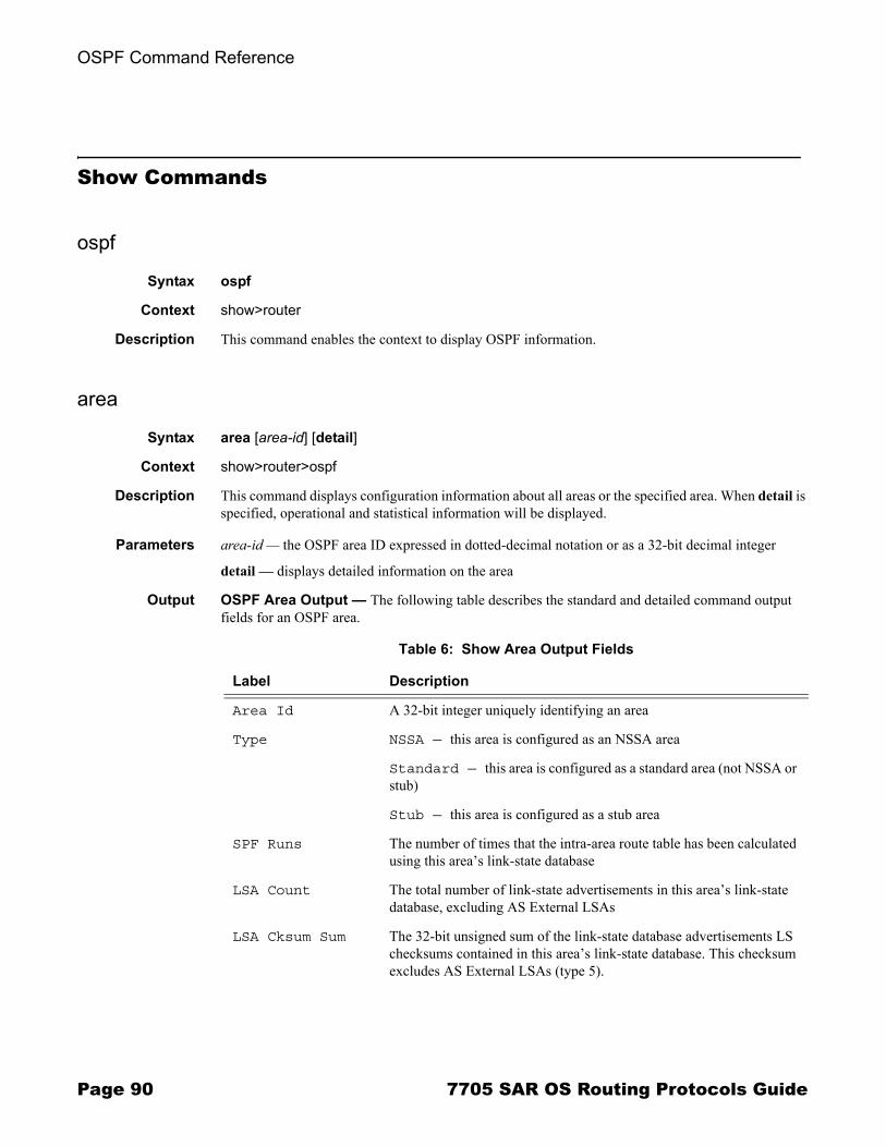
OSPF Command Reference
Show Commands
ospf
Syntax ospf
Context show>router
Description This command enables the context to display OSPF information.
area
Syntax area [area-id] [detail]
Context show>router>ospf
Description This command displays configuration information about all areas or the specified area. When detail is specified, operational and statistical information will be displayed.
Parameters area-id � the OSPF area ID expressed in dotted-decimal notation or as a 32-bit decimal integer
detail � displays detailed information on the area
Output OSPF Area Output � The following table describes the standard and detailed command output fields for an OSPF area.
Table 6: Show Area Output Fields
Label Description
Area Id A 32-bit integer uniquely identifying an area
Type NSSA — this area is configured as an NSSA area
Standard — this area is configured as a standard area (not NSSA or stub)
Stub — this area is configured as a stub area
SPF Runs The number of times that the intra-area route table has been calculated using this area�s link-state database
LSA Count The total number of link-state advertisements in this area�s link-state database, excluding AS External LSAs
LSA Cksum Sum The 32-bit unsigned sum of the link-state database advertisements LS checksums contained in this area�s link-state database. This checksum excludes AS External LSAs (type 5).
Page 90 7705 SAR OS Routing Protocols Guide
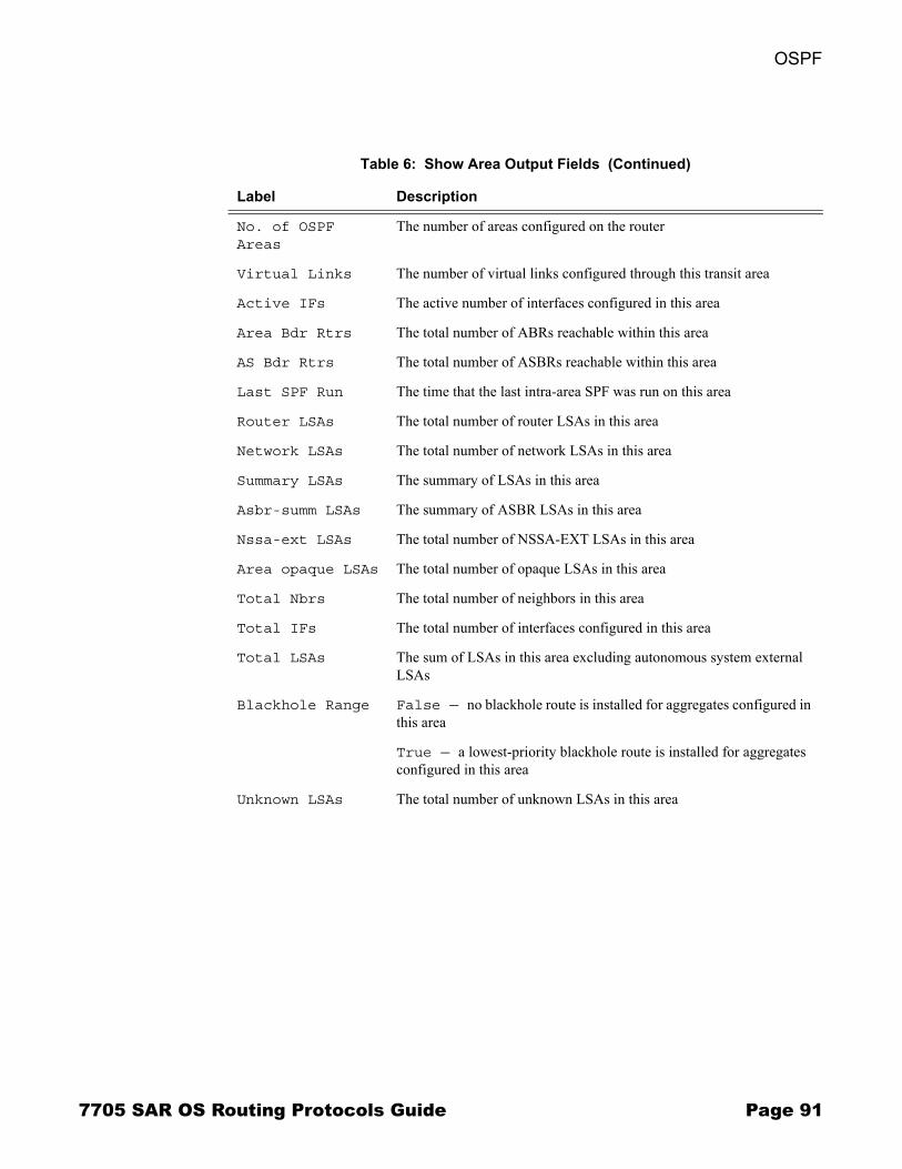
OSPF
No. of OSPF Areas
The number of areas configured on the router
Virtual Links The number of virtual links configured through this transit area
Active IFs The active number of interfaces configured in this area
Area Bdr Rtrs The total number of ABRs reachable within this area
AS Bdr Rtrs The total number of ASBRs reachable within this area
Last SPF Run The time that the last intra-area SPF was run on this area
Router LSAs The total number of router LSAs in this area
Network LSAs The total number of network LSAs in this area
Summary LSAs The summary of LSAs in this area
Asbr-summ LSAs The summary of ASBR LSAs in this area
Nssa-ext LSAs The total number of NSSA-EXT LSAs in this area
Area opaque LSAs The total number of opaque LSAs in this area
Total Nbrs The total number of neighbors in this area
Total IFs The total number of interfaces configured in this area
Total LSAs The sum of LSAs in this area excluding autonomous system external LSAs
Blackhole Range False — no blackhole route is installed for aggregates configured in this area
True — a lowest-priority blackhole route is installed for aggregates configured in this area
Unknown LSAs The total number of unknown LSAs in this area
Table 6: Show Area Output Fields (Continued)
Label Description
7705 SAR OS Routing Protocols Guide Page 91
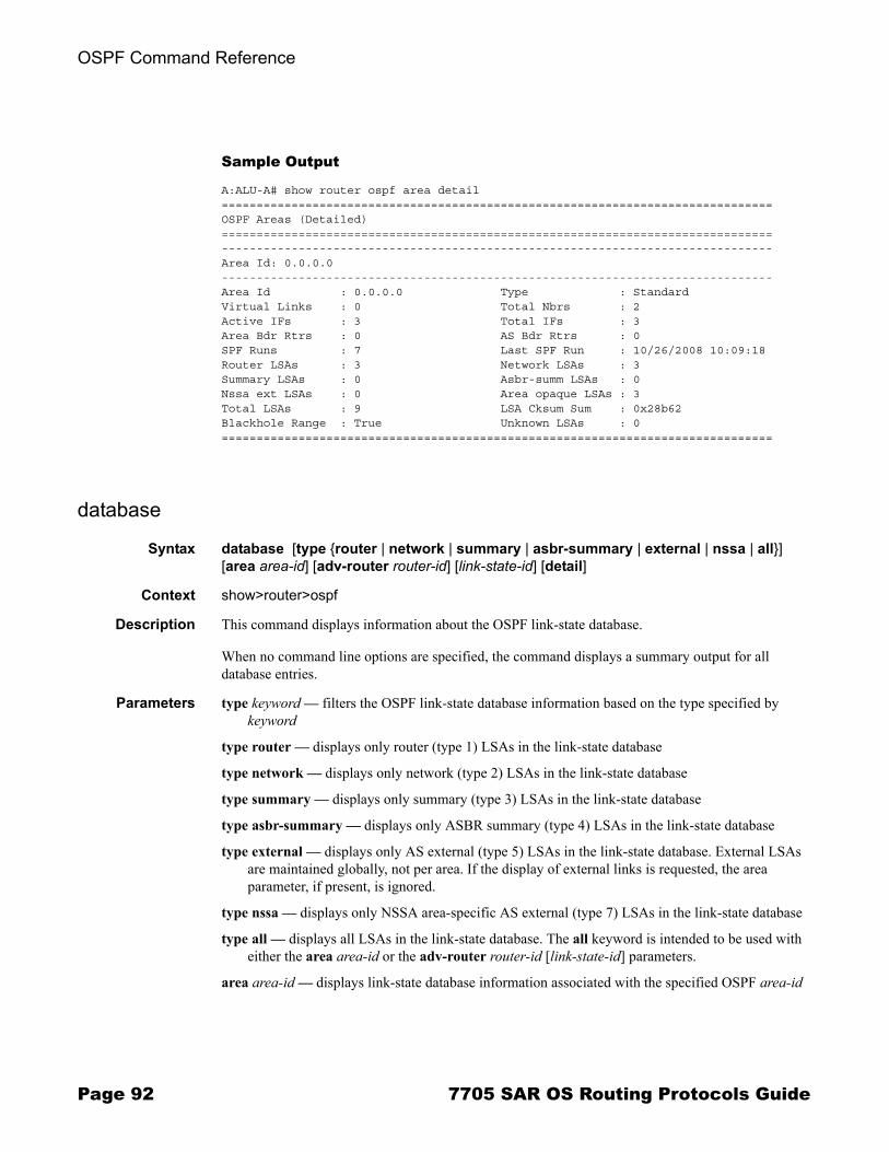
OSPF Command Reference
Sample Output
A:ALU-A# show router ospf area detail ===============================================================================OSPF Areas (Detailed)===============================================================================-------------------------------------------------------------------------------Area Id: 0.0.0.0-------------------------------------------------------------------------------Area Id : 0.0.0.0 Type : Standard Virtual Links : 0 Total Nbrs : 2 Active IFs : 3 Total IFs : 3 Area Bdr Rtrs : 0 AS Bdr Rtrs : 0 SPF Runs : 7 Last SPF Run : 10/26/2008 10:09:18 Router LSAs : 3 Network LSAs : 3 Summary LSAs : 0 Asbr-summ LSAs : 0 Nssa ext LSAs : 0 Area opaque LSAs : 3 Total LSAs : 9 LSA Cksum Sum : 0x28b62 Blackhole Range : True Unknown LSAs : 0 ===============================================================================
database
Syntax database [type {router | network | summary | asbr-summary | external | nssa | all}] [area area-id] [adv-router router-id] [link-state-id] [detail]
Context show>router>ospf
Description This command displays information about the OSPF link-state database.
When no command line options are specified, the command displays a summary output for all database entries.
Parameters type keyword � filters the OSPF link-state database information based on the type specified by keyword
type router � displays only router (type 1) LSAs in the link-state database
type network � displays only network (type 2) LSAs in the link-state database
type summary � displays only summary (type 3) LSAs in the link-state database
type asbr-summary � displays only ASBR summary (type 4) LSAs in the link-state database
type external � displays only AS external (type 5) LSAs in the link-state database. External LSAs are maintained globally, not per area. If the display of external links is requested, the area parameter, if present, is ignored.
type nssa � displays only NSSA area-specific AS external (type 7) LSAs in the link-state database
type all � displays all LSAs in the link-state database. The all keyword is intended to be used with either the area area-id or the adv-router router-id [link-state-id] parameters.
area area-id � displays link-state database information associated with the specified OSPF area-id
Page 92 7705 SAR OS Routing Protocols Guide
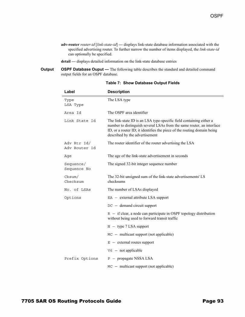
OSPF
adv-router router-id [link-state-id] � displays link-state database information associated with the specified advertising router. To further narrow the number of items displayed, the link-state-id can optionally be specified.
detail � displays detailed information on the link-state database entries
Output OSPF Database Ouput � The following table describes the standard and detailed command output fields for an OSPF database.
Table 7: Show Database Output Fields
Label Description
TypeLSA Type
The LSA type
Area Id The OSPF area identifier
Link State Id The link-state ID is an LSA type-specific field containing either a number to distinguish several LSAs from the same router, an interface ID, or a router ID; it identifies the piece of the routing domain being described by the advertisement
Adv Rtr Id/Adv Router Id
The router identifier of the router advertising the LSA
Age The age of the link-state advertisement in seconds
Sequence/Sequence No
The signed 32-bit integer sequence number
Cksum/Checksum
The 32-bit unsigned sum of the link-state advertisements' LS checksums
No. of LSAs The number of LSAs displayed
Options EA — external attribute LSA support
DC — demand circuit support
R — if clear, a node can participate in OSPF topology distribution without being used to forward transit traffic
N — type 7 LSA support
MC — multicast support (not applicable)
E — external routes support
V6 — not applicable
Prefix Options P — propagate NSSA LSA
MC — multicast support (not applicable)
7705 SAR OS Routing Protocols Guide Page 93
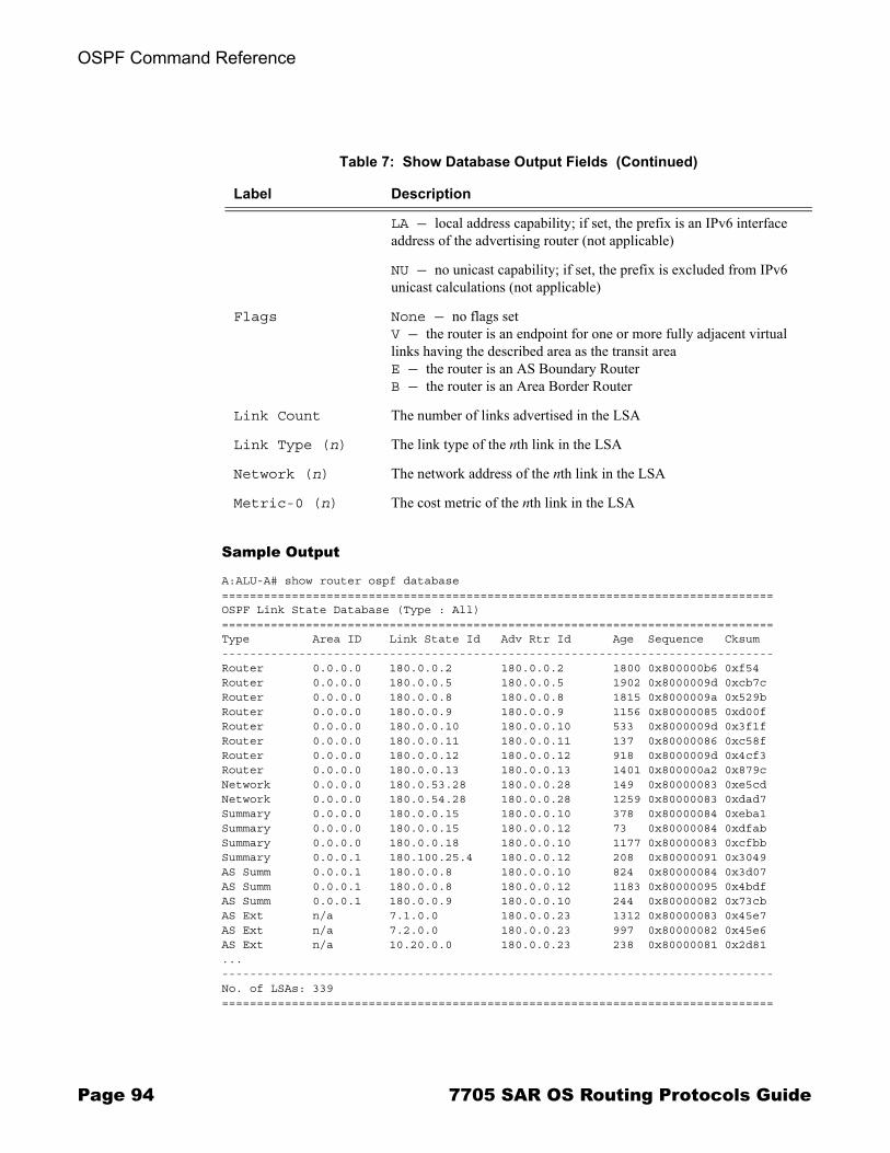
OSPF Command Reference
Sample Output
A:ALU-A# show router ospf database===============================================================================OSPF Link State Database (Type : All)===============================================================================Type Area ID Link State Id Adv Rtr Id Age Sequence Cksum-------------------------------------------------------------------------------Router 0.0.0.0 180.0.0.2 180.0.0.2 1800 0x800000b6 0xf54Router 0.0.0.0 180.0.0.5 180.0.0.5 1902 0x8000009d 0xcb7cRouter 0.0.0.0 180.0.0.8 180.0.0.8 1815 0x8000009a 0x529bRouter 0.0.0.0 180.0.0.9 180.0.0.9 1156 0x80000085 0xd00fRouter 0.0.0.0 180.0.0.10 180.0.0.10 533 0x8000009d 0x3f1fRouter 0.0.0.0 180.0.0.11 180.0.0.11 137 0x80000086 0xc58fRouter 0.0.0.0 180.0.0.12 180.0.0.12 918 0x8000009d 0x4cf3Router 0.0.0.0 180.0.0.13 180.0.0.13 1401 0x800000a2 0x879cNetwork 0.0.0.0 180.0.53.28 180.0.0.28 149 0x80000083 0xe5cdNetwork 0.0.0.0 180.0.54.28 180.0.0.28 1259 0x80000083 0xdad7Summary 0.0.0.0 180.0.0.15 180.0.0.10 378 0x80000084 0xeba1Summary 0.0.0.0 180.0.0.15 180.0.0.12 73 0x80000084 0xdfabSummary 0.0.0.0 180.0.0.18 180.0.0.10 1177 0x80000083 0xcfbbSummary 0.0.0.1 180.100.25.4 180.0.0.12 208 0x80000091 0x3049AS Summ 0.0.0.1 180.0.0.8 180.0.0.10 824 0x80000084 0x3d07AS Summ 0.0.0.1 180.0.0.8 180.0.0.12 1183 0x80000095 0x4bdfAS Summ 0.0.0.1 180.0.0.9 180.0.0.10 244 0x80000082 0x73cbAS Ext n/a 7.1.0.0 180.0.0.23 1312 0x80000083 0x45e7AS Ext n/a 7.2.0.0 180.0.0.23 997 0x80000082 0x45e6AS Ext n/a 10.20.0.0 180.0.0.23 238 0x80000081 0x2d81...-------------------------------------------------------------------------------No. of LSAs: 339===============================================================================
LA — local address capability; if set, the prefix is an IPv6 interface address of the advertising router (not applicable)
NU — no unicast capability; if set, the prefix is excluded from IPv6 unicast calculations (not applicable)
Flags None — no flags setV — the router is an endpoint for one or more fully adjacent virtual links having the described area as the transit areaE — the router is an AS Boundary RouterB — the router is an Area Border Router
Link Count The number of links advertised in the LSA
Link Type (n) The link type of the nth link in the LSA
Network (n) The network address of the nth link in the LSA
Metric-0 (n) The cost metric of the nth link in the LSA
Table 7: Show Database Output Fields (Continued)
Label Description
Page 94 7705 SAR OS Routing Protocols Guide
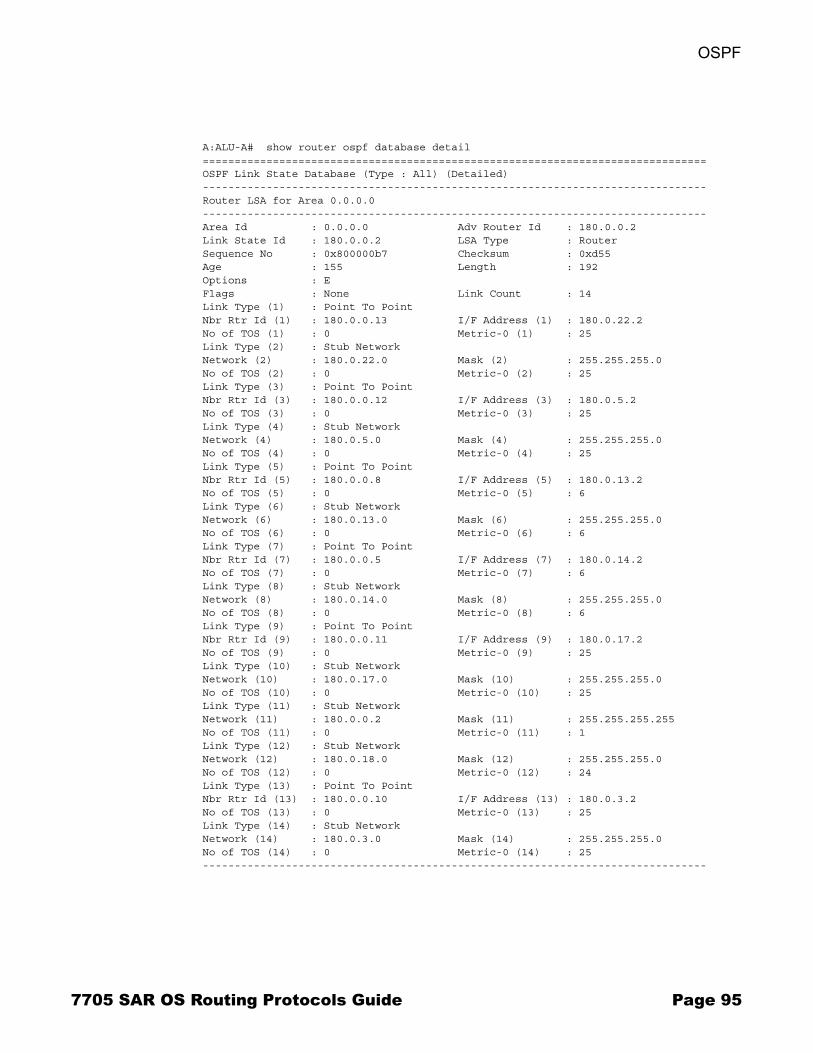
OSPF
A:ALU-A# show router ospf database detail===============================================================================OSPF Link State Database (Type : All) (Detailed)-------------------------------------------------------------------------------Router LSA for Area 0.0.0.0-------------------------------------------------------------------------------Area Id : 0.0.0.0 Adv Router Id : 180.0.0.2Link State Id : 180.0.0.2 LSA Type : RouterSequence No : 0x800000b7 Checksum : 0xd55Age : 155 Length : 192Options : EFlags : None Link Count : 14Link Type (1) : Point To PointNbr Rtr Id (1) : 180.0.0.13 I/F Address (1) : 180.0.22.2No of TOS (1) : 0 Metric-0 (1) : 25Link Type (2) : Stub NetworkNetwork (2) : 180.0.22.0 Mask (2) : 255.255.255.0No of TOS (2) : 0 Metric-0 (2) : 25Link Type (3) : Point To PointNbr Rtr Id (3) : 180.0.0.12 I/F Address (3) : 180.0.5.2No of TOS (3) : 0 Metric-0 (3) : 25Link Type (4) : Stub NetworkNetwork (4) : 180.0.5.0 Mask (4) : 255.255.255.0No of TOS (4) : 0 Metric-0 (4) : 25Link Type (5) : Point To PointNbr Rtr Id (5) : 180.0.0.8 I/F Address (5) : 180.0.13.2No of TOS (5) : 0 Metric-0 (5) : 6Link Type (6) : Stub NetworkNetwork (6) : 180.0.13.0 Mask (6) : 255.255.255.0No of TOS (6) : 0 Metric-0 (6) : 6Link Type (7) : Point To PointNbr Rtr Id (7) : 180.0.0.5 I/F Address (7) : 180.0.14.2No of TOS (7) : 0 Metric-0 (7) : 6Link Type (8) : Stub NetworkNetwork (8) : 180.0.14.0 Mask (8) : 255.255.255.0No of TOS (8) : 0 Metric-0 (8) : 6Link Type (9) : Point To PointNbr Rtr Id (9) : 180.0.0.11 I/F Address (9) : 180.0.17.2No of TOS (9) : 0 Metric-0 (9) : 25Link Type (10) : Stub NetworkNetwork (10) : 180.0.17.0 Mask (10) : 255.255.255.0No of TOS (10) : 0 Metric-0 (10) : 25Link Type (11) : Stub NetworkNetwork (11) : 180.0.0.2 Mask (11) : 255.255.255.255No of TOS (11) : 0 Metric-0 (11) : 1Link Type (12) : Stub NetworkNetwork (12) : 180.0.18.0 Mask (12) : 255.255.255.0No of TOS (12) : 0 Metric-0 (12) : 24Link Type (13) : Point To PointNbr Rtr Id (13) : 180.0.0.10 I/F Address (13) : 180.0.3.2No of TOS (13) : 0 Metric-0 (13) : 25Link Type (14) : Stub NetworkNetwork (14) : 180.0.3.0 Mask (14) : 255.255.255.0No of TOS (14) : 0 Metric-0 (14) : 25-------------------------------------------------------------------------------
7705 SAR OS Routing Protocols Guide Page 95
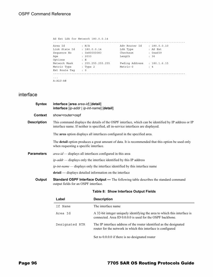
OSPF Command Reference
AS Ext LSA for Network 180.0.0.14-------------------------------------------------------------------------------Area Id : N/A Adv Router Id : 180.0.0.10Link State Id : 180.0.0.14 LSA Type : AS ExtSequence No : 0x80000083 Checksum : 0xa659Age : 2033 Length : 36Options : ENetwork Mask : 255.255.255.255 Fwding Address : 180.1.6.15Metric Type : Type 2 Metric-0 : 4Ext Route Tag : 0-------------------------------------------------------------------------------...A:ALU-A#
interface
Syntax interface [area area-id] [detail]interface [ip-addr | ip-int-name] [detail]
Context show>router>ospf
Description This command displays the details of the OSPF interface, which can be identified by IP address or IP interface name. If neither is specified, all in-service interfaces are displayed.
The area option displays all interfaces configured in the specified area.
The detail option produces a great amount of data. It is recommended that this option be used only when requesting a specific interface.
Parameters area-id � displays all interfaces configured in this area
ip-addr � displays only the interface identified by this IP address
ip-int-name � displays only the interface identified by this interface name
detail � displays detailed information on the interface
Output Standard OSPF Interface Output � The following table describes the standard command output fields for an OSPF interface.
Table 8: Show Interface Output Fields
Label Description
If Name The interface name
Area Id A 32-bit integer uniquely identifying the area to which this interface is connected. Area ID 0.0.0.0 is used for the OSPF backbone.
Designated RTR The IP interface address of the router identified as the designated router for the network in which this interface is configured
Set to 0.0.0.0 if there is no designated router
Page 96 7705 SAR OS Routing Protocols Guide

OSPF
Sample Output
A:ALU-A# show router ospf interface
===============================================================================OSPF Interfaces===============================================================================If Name Area Id Designated Rtr Bkup Desig Rtr Adm Oper-------------------------------------------------------------------------------system 0.0.0.1 10.10.10.104 0.0.0.0 Up DRto-103 0.0.0.20 0.0.0.0 0.0.0.0 Up Down-------------------------------------------------------------------------------No. of OSPF Interfaces: 2===============================================================================
Bkup Desig Rtr The IP interface address of the router identified as the backup designated router for the network in which this interface is configured
Set to 0.0.0.0 if there is no backup designated router
Adm Dn — OSPF on this interface is administratively shut down
Up — OSPF on this interface is administratively enabled
Opr Down — the initial interface state. In this state, the lower-level protocols have indicated that the interface is unusable.
Wait — the router is trying to determine the identity of the (backup) designated router for the network
PToP — the interface is operational, and connects either to a physical point-to-point network or to a virtual link
DR — this router is the designated router for this network
BDR — this router is the backup designated router for this network
ODR — the interface is operational and part of a broadcast or NBMA network on which another router has been selected to be the designated router
No. of OSPF Interfaces
The number of interfaces listed
Table 8: Show Interface Output Fields (Continued)
Label Description
7705 SAR OS Routing Protocols Guide Page 97
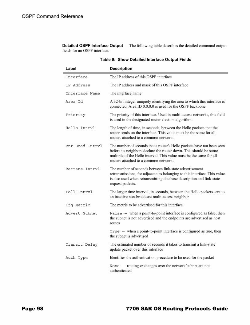
OSPF Command Reference
Detailed OSPF Interface Output � The following table describes the detailed command output fields for an OSPF interface.
Table 9: Show Detailed Interface Output Fields
Label Description
Interface The IP address of this OSPF interface
IP Address The IP address and mask of this OSPF interface
Interface Name The interface name
Area Id A 32-bit integer uniquely identifying the area to which this interface is connected. Area ID 0.0.0.0 is used for the OSPF backbone.
Priority The priority of this interface. Used in multi-access networks, this field is used in the designated router election algorithm.
Hello Intrvl The length of time, in seconds, between the Hello packets that the router sends on the interface. This value must be the same for all routers attached to a common network.
Rtr Dead Intrvl The number of seconds that a router's Hello packets have not been seen before its neighbors declare the router down. This should be some multiple of the Hello interval. This value must be the same for all routers attached to a common network.
Retrans Intrvl The number of seconds between link-state advertisement retransmissions, for adjacencies belonging to this interface. This value is also used when retransmitting database description and link-state request packets.
Poll Intrvl The larger time interval, in seconds, between the Hello packets sent to an inactive non-broadcast multi-access neighbor
Cfg Metric The metric to be advertised for this interface
Advert Subnet False — when a point-to-point interface is configured as false, then the subnet is not advertised and the endpoints are advertised as host routes
True — when a point-to-point interface is configured as true, then the subnet is advertised
Transit Delay The estimated number of seconds it takes to transmit a link-state update packet over this interface
Auth Type Identifies the authentication procedure to be used for the packet
None — routing exchanges over the network/subnet are not authenticated
Page 98 7705 SAR OS Routing Protocols Guide
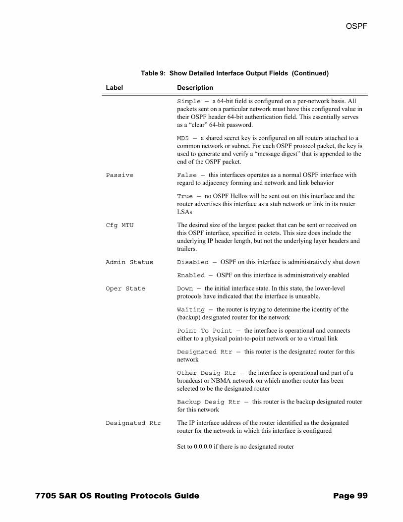
OSPF
Simple — a 64-bit field is configured on a per-network basis. All packets sent on a particular network must have this configured value in their OSPF header 64-bit authentication field. This essentially serves as a �clear� 64-bit password.
MD5 — a shared secret key is configured on all routers attached to a common network or subnet. For each OSPF protocol packet, the key is used to generate and verify a �message digest� that is appended to the end of the OSPF packet.
Passive False — this interfaces operates as a normal OSPF interface with regard to adjacency forming and network and link behavior
True — no OSPF Hellos will be sent out on this interface and the router advertises this interface as a stub network or link in its router LSAs
Cfg MTU The desired size of the largest packet that can be sent or received on this OSPF interface, specified in octets. This size does include the underlying IP header length, but not the underlying layer headers and trailers.
Admin Status Disabled — OSPF on this interface is administratively shut down
Enabled — OSPF on this interface is administratively enabled
Oper State Down — the initial interface state. In this state, the lower-level protocols have indicated that the interface is unusable.
Waiting — the router is trying to determine the identity of the (backup) designated router for the network
Point To Point — the interface is operational and connects either to a physical point-to-point network or to a virtual link
Designated Rtr — this router is the designated router for this network
Other Desig Rtr — the interface is operational and part of a broadcast or NBMA network on which another router has been selected to be the designated router
Backup Desig Rtr — this router is the backup designated router for this network
Designated Rtr The IP interface address of the router identified as the designated router for the network in which this interface is configured
Set to 0.0.0.0 if there is no designated router
Table 9: Show Detailed Interface Output Fields (Continued)
Label Description
7705 SAR OS Routing Protocols Guide Page 99
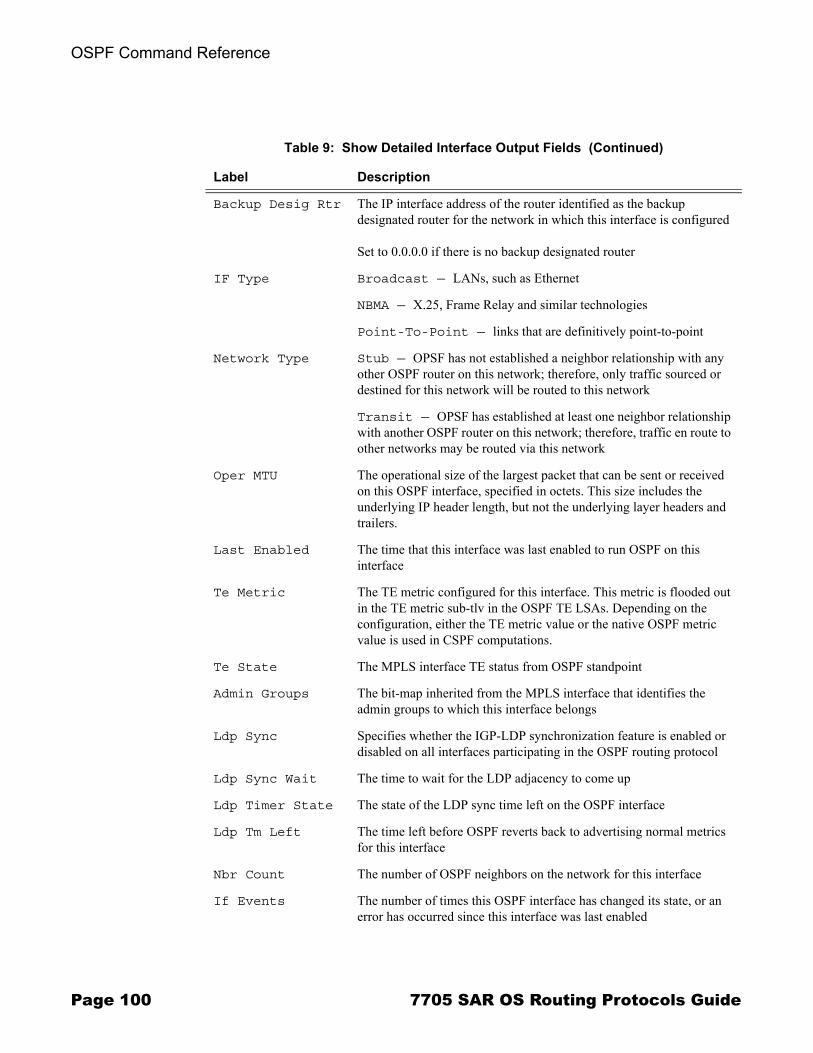
OSPF Command Reference
Backup Desig Rtr The IP interface address of the router identified as the backup designated router for the network in which this interface is configured
Set to 0.0.0.0 if there is no backup designated router
IF Type Broadcast — LANs, such as Ethernet
NBMA — X.25, Frame Relay and similar technologies
Point-To-Point — links that are definitively point-to-point
Network Type Stub — OPSF has not established a neighbor relationship with any other OSPF router on this network; therefore, only traffic sourced or destined for this network will be routed to this network
Transit — OPSF has established at least one neighbor relationship with another OSPF router on this network; therefore, traffic en route to other networks may be routed via this network
Oper MTU The operational size of the largest packet that can be sent or received on this OSPF interface, specified in octets. This size includes the underlying IP header length, but not the underlying layer headers and trailers.
Last Enabled The time that this interface was last enabled to run OSPF on this interface
Te Metric The TE metric configured for this interface. This metric is flooded out in the TE metric sub-tlv in the OSPF TE LSAs. Depending on the configuration, either the TE metric value or the native OSPF metric value is used in CSPF computations.
Te State The MPLS interface TE status from OSPF standpoint
Admin Groups The bit-map inherited from the MPLS interface that identifies the admin groups to which this interface belongs
Ldp Sync Specifies whether the IGP-LDP synchronization feature is enabled or disabled on all interfaces participating in the OSPF routing protocol
Ldp Sync Wait The time to wait for the LDP adjacency to come up
Ldp Timer State The state of the LDP sync time left on the OSPF interface
Ldp Tm Left The time left before OSPF reverts back to advertising normal metrics for this interface
Nbr Count The number of OSPF neighbors on the network for this interface
If Events The number of times this OSPF interface has changed its state, or an error has occurred since this interface was last enabled
Table 9: Show Detailed Interface Output Fields (Continued)
Label Description
Page 100 7705 SAR OS Routing Protocols Guide

OSPF
Tot Rx Packets The total number of OSPF packets received on this interface since this interface was last enabled
Tot Tx Packets The total number of OSPF packets transmitted on this interface since this interface was last enabled
Rx Hellos The total number of OSPF Hello packets received on this interface since this interface was last enabled
Tx Hellos The total number of OSPF Hello packets transmitted on this interface since this interface was last enabled
Rx DBDs The total number of OSPF database description packets received on this interface since this interface was last enabled
Tx DBDs The total number of OSPF database description packets transmitted on this interface since this interface was last enabled
Rx LSRs The total number of Link-State Requests (LSRs) received on this interface since this interface was last enabled
Tx LSRs The total number of Link-State Requests (LSRs) transmitted on this interface since this interface was last enabled
Rx LSUs The total number of Link-State Updates (LSUs) received on this interface since this interface was last enabled
Tx LSUs The total number of Link-State Updates (LSUs) transmitted on this interface since this interface was last enabled
Rx LS Acks The total number of Link-State Acknowledgements received on this interface since this interface was last enabled
Tx LS Acks The total number of Link-State Acknowledgements transmitted on this interface since this interface was last enabled
Retransmits The total number of OSPF retransmits sent on this interface since this interface was last enabled
Discards The total number of OSPF packets discarded on this interface since this interface was last enabled
Bad Networks The total number of OSPF packets received with invalid network or mask since this interface was last enabled
Bad Virt Links The total number of OSPF packets received on this interface that are destined for a virtual link that does not exist since this interface was last enabled
Bad Areas The total number of OSPF packets received with an area mismatch since this interface was last enabled
Table 9: Show Detailed Interface Output Fields (Continued)
Label Description
7705 SAR OS Routing Protocols Guide Page 101
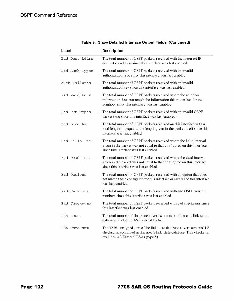
OSPF Command Reference
Bad Dest Addrs The total number of OSPF packets received with the incorrect IP destination address since this interface was last enabled
Bad Auth Types The total number of OSPF packets received with an invalid authorization type since this interface was last enabled
Auth Failures The total number of OSPF packets received with an invalid authorization key since this interface was last enabled
Bad Neighbors The total number of OSPF packets received where the neighbor information does not match the information this router has for the neighbor since this interface was last enabled
Bad Pkt Types The total number of OSPF packets received with an invalid OSPF packet type since this interface was last enabled
Bad Lengths The total number of OSPF packets received on this interface with a total length not equal to the length given in the packet itself since this interface was last enabled
Bad Hello Int. The total number of OSPF packets received where the hello interval given in the packet was not equal to that configured on this interface since this interface was last enabled
Bad Dead Int. The total number of OSPF packets received where the dead interval given in the packet was not equal to that configured on this interface since this interface was last enabled
Bad Options The total number of OSPF packets received with an option that does not match those configured for this interface or area since this interface was last enabled
Bad Versions The total number of OSPF packets received with bad OSPF version numbers since this interface was last enabled
Bad Checksums The total number of OSPF packets received with bad checksums since this interface was last enabled
LSA Count The total number of link-state advertisements in this area�s link-state database, excluding AS External LSAs
LSA Checksum The 32-bit unsigned sum of the link-state database advertisements� LS checksums contained in this area�s link-state database. This checksum excludes AS External LSAs (type 5).
Table 9: Show Detailed Interface Output Fields (Continued)
Label Description
Page 102 7705 SAR OS Routing Protocols Guide

OSPF
Sample Output
A:ALU-A# show router ospf interface
===============================================================================OSPF Interface (Detailed) : system===============================================================================-------------------------------------------------------------------------------Configuration-------------------------------------------------------------------------------IP Address : 10.10.10.104Area Id : 0.0.0.1 Priority : 1Hello Intrvl : 10 sec Rtr Dead Intrvl : 40 secRetrans Intrvl : 5 sec Poll Intrvl : 120 secCfg Metric : 0 Advert Subnet : TrueTransit Delay : 1 Auth Type : NonePassive : True Cfg MTU : 0-------------------------------------------------------------------------------State-------------------------------------------------------------------------------Admin Status : Enabled Oper State : Designated RtrDesignated Rtr : 10.10.10.104 Backup Desig Rtr : 0.0.0.0IF Type : Broadcast Network Type : TransitOper MTU : 1500 Last Enabled : 01/26/2009 23:28:25Oper Metric : 0 Bfd Enabled : NoTe Metric : 0 Te State : DownAdmin Groups : NoneLdp Sync : outOfService Ldp Sync Wait : DisabledLdp Timer State : Disabled Ldp Tm Left : 0-------------------------------------------------------------------------------Statistics-------------------------------------------------------------------------------Nbr Count : 0 If Events : 2Tot Rx Packets : 0 Tot Tx Packets : 0Rx Hellos : 0 Tx Hellos : 0Rx DBDs : 0 Tx DBDs : 0Rx LSRs : 0 Tx LSRs : 0Rx LSUs : 0 Tx LSUs : 0Rx LS Acks : 0 Tx LS Acks : 0Retransmits : 0 Discards : 0Bad Networks : 0 Bad Virt Links : 0Bad Areas : 0 Bad Dest Addrs : 0Bad Auth Types : 0 Auth Failures : 0Bad Neighbors : 0 Bad Pkt Types : 0Bad Lengths : 0 Bad Hello Int. : 0Bad Dead Int. : 0 Bad Options : 0Bad Versions : 0 Bad Checksums : 0LSA Count : 0 LSA Checksum : 0x0 -------------------------------------------------------------------------------
7705 SAR OS Routing Protocols Guide Page 103

OSPF Command Reference
neighbor
Syntax neighbor [ip-int-name] [router-id] [detail]neighbor [remote ip-address] [detail]
Context show>router>ospf
Description This command displays all neighbor information or all information on neighbors of a router identified by interface name or router ID.
The detail option produces a large amount of data. It is recommended that this option be used only when requesting a specific neighbor.
Parameters ip-int-name � displays neighbor information only for neighbors of the interface identified by the interface name
router-id � displays neighbor information for the neighbor identified by the the specified router ID
detail � displays detailed information on the interface
ip-address � displays information for a far-end neighbor, identified by IP address
Output Standard OSPF Neighbor Output � The following table describes the standard command output fields for an OSPF neighbor.
Table 10: Show Neighbor Output Fields
Label Description
Interface Name The interface name or IP address this neighbor is using in its IP source address. Note that, on links with no address, this will not be 0.0.0.0, but the address of another of the neighbor's interfaces.
Rtr Id A 32-bit integer uniquely identifying the neighboring router in the Autonomous System
State Down — the initial state of a neighbor conversation. It indicates that there has been no recent information received from the neighbor.
Attempt — this state is only valid for neighbors attached to NBMA networks. It indicates that no recent information has been received from the neighbor, but that a more concerted effort should be made to contact the neighbor.
Init — in this state, a Hello packet has recently been seen from the neighbor. However, bidirectional communication has not yet been established with the neighbor (that is, the router itself did not appear in the neighbor's Hello packet).
Two Way — in this state, communication between the two routers is bidirectional
Page 104 7705 SAR OS Routing Protocols Guide
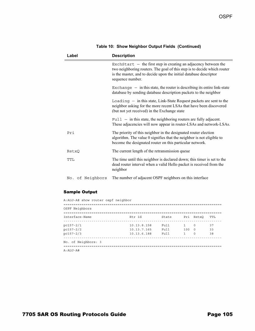
OSPF
Sample Output
A:ALU-A# show router ospf neighbor===============================================================================OSPF Neighbors===============================================================================Interface-Name Rtr Id State Pri RetxQ TTL-------------------------------------------------------------------------------pc157-2/1 10.13.8.158 Full 1 0 37pc157-2/2 10.13.7.165 Full 100 0 33pc157-2/3 10.13.6.188 Full 1 0 38-------------------------------------------------------------------------------No. of Neighbors: 3===============================================================================A:ALU-A#
ExchStart — the first step in creating an adjacency between the two neighboring routers. The goal of this step is to decide which router is the master, and to decide upon the initial database descriptor sequence number.
Exchange — in this state, the router is describing its entire link-state database by sending database description packets to the neighbor
Loading — in this state, Link-State Request packets are sent to the neighbor asking for the more recent LSAs that have been discovered (but not yet received) in the Exchange state
Full — in this state, the neighboring routers are fully adjacent. These adjacencies will now appear in router-LSAs and network-LSAs.
Pri The priority of this neighbor in the designated router election algorithm. The value 0 signifies that the neighbor is not eligible to become the designated router on this particular network.
RetxQ The current length of the retransmission queue
TTL The time until this neighbor is declared down; this timer is set to the dead router interval when a valid Hello packet is received from the neighbor
No. of Neighbors The number of adjacent OSPF neighbors on this interface
Table 10: Show Neighbor Output Fields (Continued)
Label Description
7705 SAR OS Routing Protocols Guide Page 105
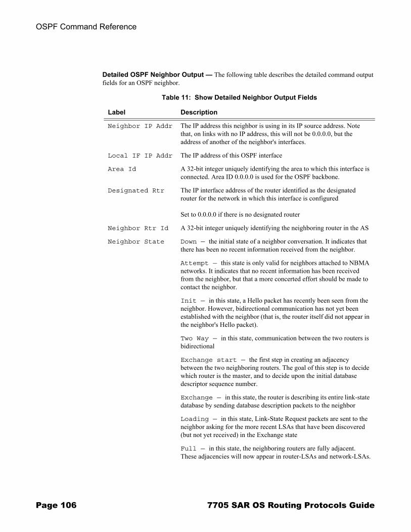
OSPF Command Reference
Detailed OSPF Neighbor Output � The following table describes the detailed command output fields for an OSPF neighbor.
Table 11: Show Detailed Neighbor Output Fields
Label Description
Neighbor IP Addr The IP address this neighbor is using in its IP source address. Note that, on links with no IP address, this will not be 0.0.0.0, but the address of another of the neighbor's interfaces.
Local IF IP Addr The IP address of this OSPF interface
Area Id A 32-bit integer uniquely identifying the area to which this interface is connected. Area ID 0.0.0.0 is used for the OSPF backbone.
Designated Rtr The IP interface address of the router identified as the designated router for the network in which this interface is configured
Set to 0.0.0.0 if there is no designated router
Neighbor Rtr Id A 32-bit integer uniquely identifying the neighboring router in the AS
Neighbor State Down — the initial state of a neighbor conversation. It indicates that there has been no recent information received from the neighbor.
Attempt — this state is only valid for neighbors attached to NBMA networks. It indicates that no recent information has been received from the neighbor, but that a more concerted effort should be made to contact the neighbor.
Init — in this state, a Hello packet has recently been seen from the neighbor. However, bidirectional communication has not yet been established with the neighbor (that is, the router itself did not appear in the neighbor's Hello packet).
Two Way — in this state, communication between the two routers is bidirectional
Exchange start — the first step in creating an adjacency between the two neighboring routers. The goal of this step is to decide which router is the master, and to decide upon the initial database descriptor sequence number.
Exchange — in this state, the router is describing its entire link-state database by sending database description packets to the neighbor
Loading — in this state, Link-State Request packets are sent to the neighbor asking for the more recent LSAs that have been discovered (but not yet received) in the Exchange state
Full — in this state, the neighboring routers are fully adjacent. These adjacencies will now appear in router-LSAs and network-LSAs.
Page 106 7705 SAR OS Routing Protocols Guide

OSPF
Priority The priority of this neighbor in the designated router election algorithm. The value 0 signifies that the neighbor is not eligible to become the designated router on this particular network.
Retrans Q Length The current length of the retransmission queue
Options E — external routes support
MC — multicast support (not applicable)
N/P — type 7 LSA support
EA — external attribute LSA support
DC — demand circuit support
O — opaque LSA support
Backup Desig Rtr The IP interface address of the router identified as the backup designated router for the network in which this interface is configured
Set to 0.0.0.0 if there is no backup designated router
Events The number of times this neighbor relationship has changed state, or an error has occurred
Last Event Time The time that the last event occurred that affected the adjacency to the neighbor
Up Time The uninterrupted time, in hundredths of seconds, that the adjacency to this neighbor has been up. To evaluate when the last state change occurred, see last event time.
Time Before Dead The time until this neighbor is declared down; this timer is set to the dead router interval when a valid Hello packet is received from the neighbor
Bad Nbr States The total number of OSPF packets received when the neighbor state was not expecting to receive this packet type since this interface was last enabled
LSA Inst fails The total number of times that an LSA could not be installed into the link-state database due to a resource allocation issue since this interface was last enabled
Bad Seq Nums The total number of times that a database description packet was received with a sequence number mismatch since this interface was last enabled
Table 11: Show Detailed Neighbor Output Fields (Continued)
Label Description
7705 SAR OS Routing Protocols Guide Page 107
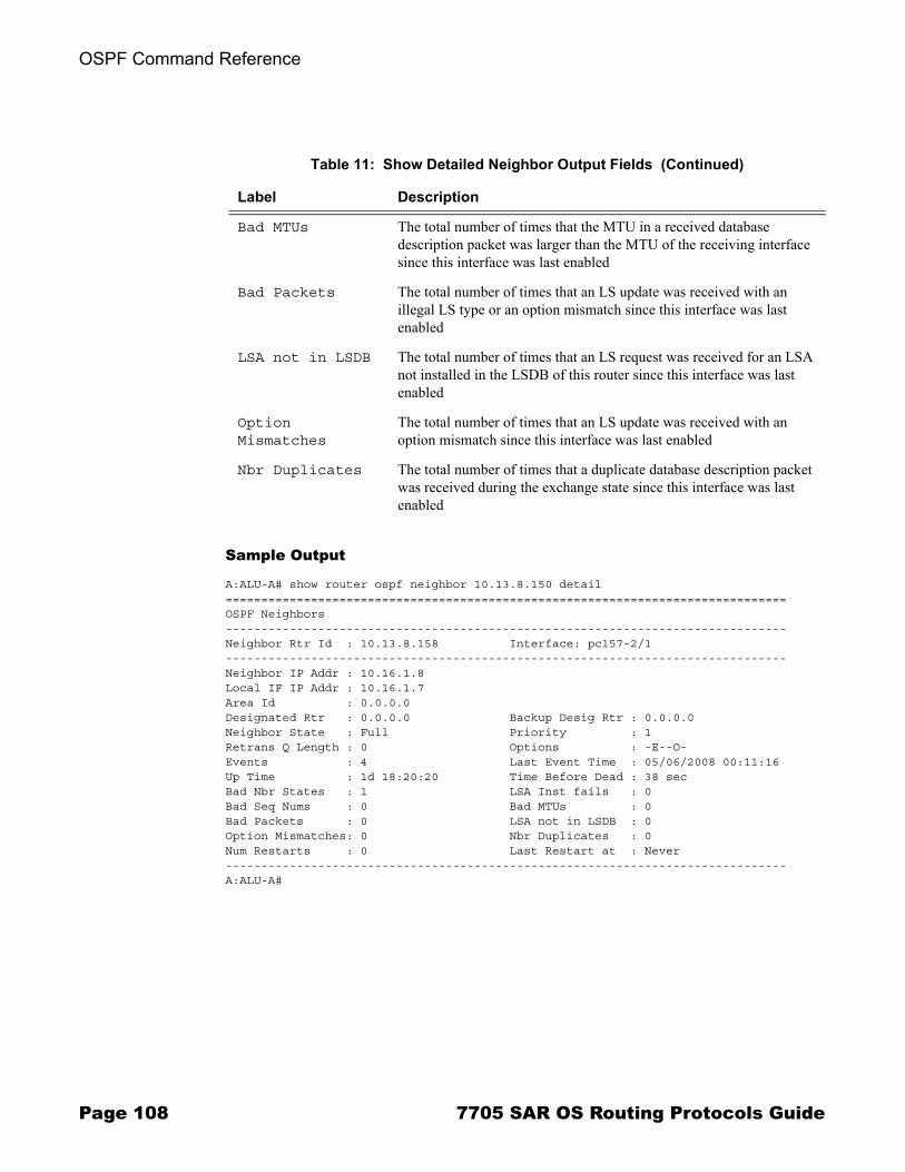
OSPF Command Reference
Sample Output
A:ALU-A# show router ospf neighbor 10.13.8.150 detail===============================================================================OSPF Neighbors-------------------------------------------------------------------------------Neighbor Rtr Id : 10.13.8.158 Interface: pc157-2/1-------------------------------------------------------------------------------Neighbor IP Addr : 10.16.1.8Local IF IP Addr : 10.16.1.7Area Id : 0.0.0.0Designated Rtr : 0.0.0.0 Backup Desig Rtr : 0.0.0.0Neighbor State : Full Priority : 1Retrans Q Length : 0 Options : -E--O-Events : 4 Last Event Time : 05/06/2008 00:11:16Up Time : 1d 18:20:20 Time Before Dead : 38 secBad Nbr States : 1 LSA Inst fails : 0Bad Seq Nums : 0 Bad MTUs : 0Bad Packets : 0 LSA not in LSDB : 0Option Mismatches: 0 Nbr Duplicates : 0Num Restarts : 0 Last Restart at : Never-------------------------------------------------------------------------------A:ALU-A#
Bad MTUs The total number of times that the MTU in a received database description packet was larger than the MTU of the receiving interface since this interface was last enabled
Bad Packets The total number of times that an LS update was received with an illegal LS type or an option mismatch since this interface was last enabled
LSA not in LSDB The total number of times that an LS request was received for an LSA not installed in the LSDB of this router since this interface was last enabled
Option Mismatches
The total number of times that an LS update was received with an option mismatch since this interface was last enabled
Nbr Duplicates The total number of times that a duplicate database description packet was received during the exchange state since this interface was last enabled
Table 11: Show Detailed Neighbor Output Fields (Continued)
Label Description
Page 108 7705 SAR OS Routing Protocols Guide
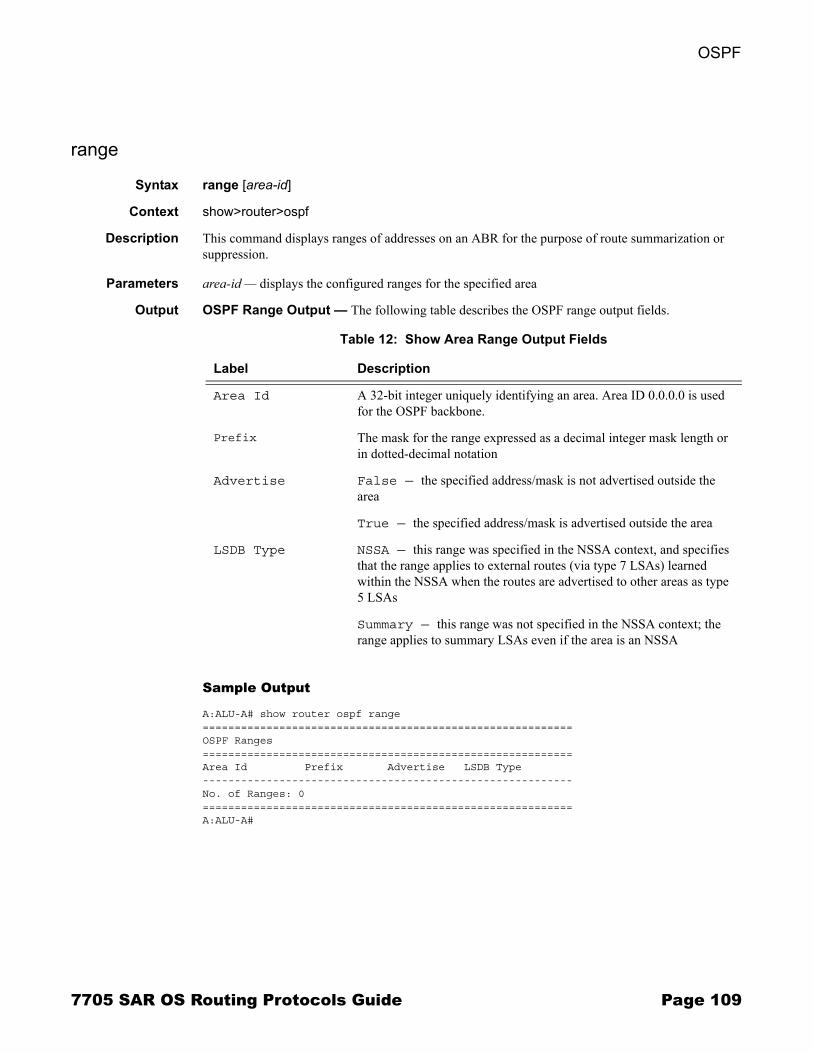
OSPF
range
Syntax range [area-id]
Context show>router>ospf
Description This command displays ranges of addresses on an ABR for the purpose of route summarization or suppression.
Parameters area-id � displays the configured ranges for the specified area
Output OSPF Range Output � The following table describes the OSPF range output fields.
Sample Output
A:ALU-A# show router ospf range==========================================================OSPF Ranges ==========================================================Area Id Prefix Advertise LSDB Type ----------------------------------------------------------No. of Ranges: 0 ==========================================================A:ALU-A#
Table 12: Show Area Range Output Fields
Label Description
Area Id A 32-bit integer uniquely identifying an area. Area ID 0.0.0.0 is used for the OSPF backbone.
Prefix The mask for the range expressed as a decimal integer mask length or in dotted-decimal notation
Advertise False — the specified address/mask is not advertised outside the area
True — the specified address/mask is advertised outside the area
LSDB Type NSSA — this range was specified in the NSSA context, and specifies that the range applies to external routes (via type 7 LSAs) learned within the NSSA when the routes are advertised to other areas as type 5 LSAs
Summary — this range was not specified in the NSSA context; the range applies to summary LSAs even if the area is an NSSA
7705 SAR OS Routing Protocols Guide Page 109
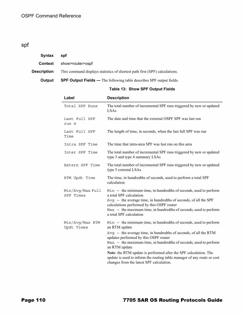
OSPF Command Reference
spf
Syntax spf
Context show>router>ospf
Description This command displays statistics of shortest path first (SPF) calculations.
Output SPF Output Fields � The following table describes SPF output fields.
Table 13: Show SPF Output Fields
Label Description
Total SPF Runs The total number of incremental SPF runs triggered by new or updated LSAs
Last Full SPF run @
The date and time that the external OSPF SPF was last run
Last Full SPF Time
The length of time, in seconds, when the last full SPF was run
Intra SPF Time The time that intra-area SPF was last run on this area
Inter SPF Time The total number of incremental SPF runs triggered by new or updated type 3 and type 4 summary LSAs
Extern SPF Time The total number of incremental SPF runs triggered by new or updated type 5 external LSAs
RTM Updt Time The time, in hundredths of seconds, used to perform a total SPF calculation
Min/Avg/Max Full SPF Times
Min — the minimum time, in hundredths of seconds, used to perform a total SPF calculationAvg — the average time, in hundredths of seconds, of all the SPF calculations performed by this OSPF routerMax — the maximum time, in hundredths of seconds, used to perform a total SPF calculation
Min/Avg/Max RTM Updt Times
Min — the minimum time, in hundredths of seconds, used to perform an RTM updateAvg — the average time, in hundredths of seconds, of all the RTM updates performed by this OSPF routerMax — the maximum time, in hundredths of seconds, used to perform an RTM updateNote: the RTM update is performed after the SPF calculation. The update is used to inform the routing table manager of any route or cost changes from the latest SPF calculation.
Page 110 7705 SAR OS Routing Protocols Guide
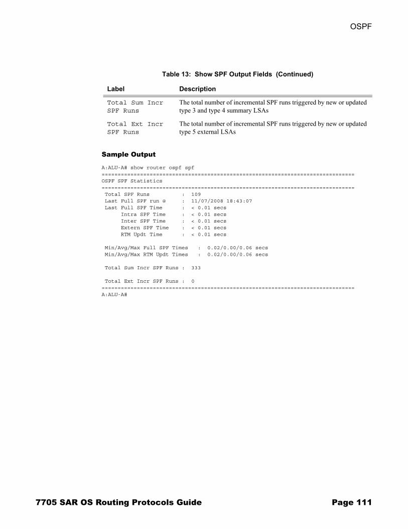
OSPF
Sample Output
A:ALU-A# show router ospf spf===============================================================================OSPF SPF Statistics=============================================================================== Total SPF Runs : 109 Last Full SPF run @ : 11/07/2008 18:43:07 Last Full SPF Time : < 0.01 secs Intra SPF Time : < 0.01 secs Inter SPF Time : < 0.01 secs Extern SPF Time : < 0.01 secs RTM Updt Time : < 0.01 secs
Min/Avg/Max Full SPF Times : 0.02/0.00/0.06 secs Min/Avg/Max RTM Updt Times : 0.02/0.00/0.06 secs
Total Sum Incr SPF Runs : 333
Total Ext Incr SPF Runs : 0===============================================================================A:ALU-A#
Total Sum Incr SPF Runs
The total number of incremental SPF runs triggered by new or updated type 3 and type 4 summary LSAs
Total Ext Incr SPF Runs
The total number of incremental SPF runs triggered by new or updated type 5 external LSAs
Table 13: Show SPF Output Fields (Continued)
Label Description
7705 SAR OS Routing Protocols Guide Page 111
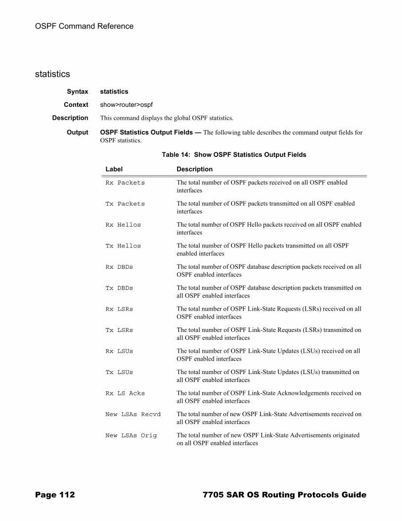
OSPF Command Reference
statistics
Syntax statistics
Context show>router>ospf
Description This command displays the global OSPF statistics.
Output OSPF Statistics Output Fields � The following table describes the command output fields for OSPF statistics.
Table 14: Show OSPF Statistics Output Fields
Label Description
Rx Packets The total number of OSPF packets received on all OSPF enabled interfaces
Tx Packets The total number of OSPF packets transmitted on all OSPF enabled interfaces
Rx Hellos The total number of OSPF Hello packets received on all OSPF enabled interfaces
Tx Hellos The total number of OSPF Hello packets transmitted on all OSPF enabled interfaces
Rx DBDs The total number of OSPF database description packets received on all OSPF enabled interfaces
Tx DBDs The total number of OSPF database description packets transmitted on all OSPF enabled interfaces
Rx LSRs The total number of OSPF Link-State Requests (LSRs) received on all OSPF enabled interfaces
Tx LSRs The total number of OSPF Link-State Requests (LSRs) transmitted on all OSPF enabled interfaces
Rx LSUs The total number of OSPF Link-State Updates (LSUs) received on all OSPF enabled interfaces
Tx LSUs The total number of OSPF Link-State Updates (LSUs) transmitted on all OSPF enabled interfaces
Rx LS Acks The total number of OSPF Link-State Acknowledgements received on all OSPF enabled interfaces
New LSAs Recvd The total number of new OSPF Link-State Advertisements received on all OSPF enabled interfaces
New LSAs Orig The total number of new OSPF Link-State Advertisements originated on all OSPF enabled interfaces
Page 112 7705 SAR OS Routing Protocols Guide
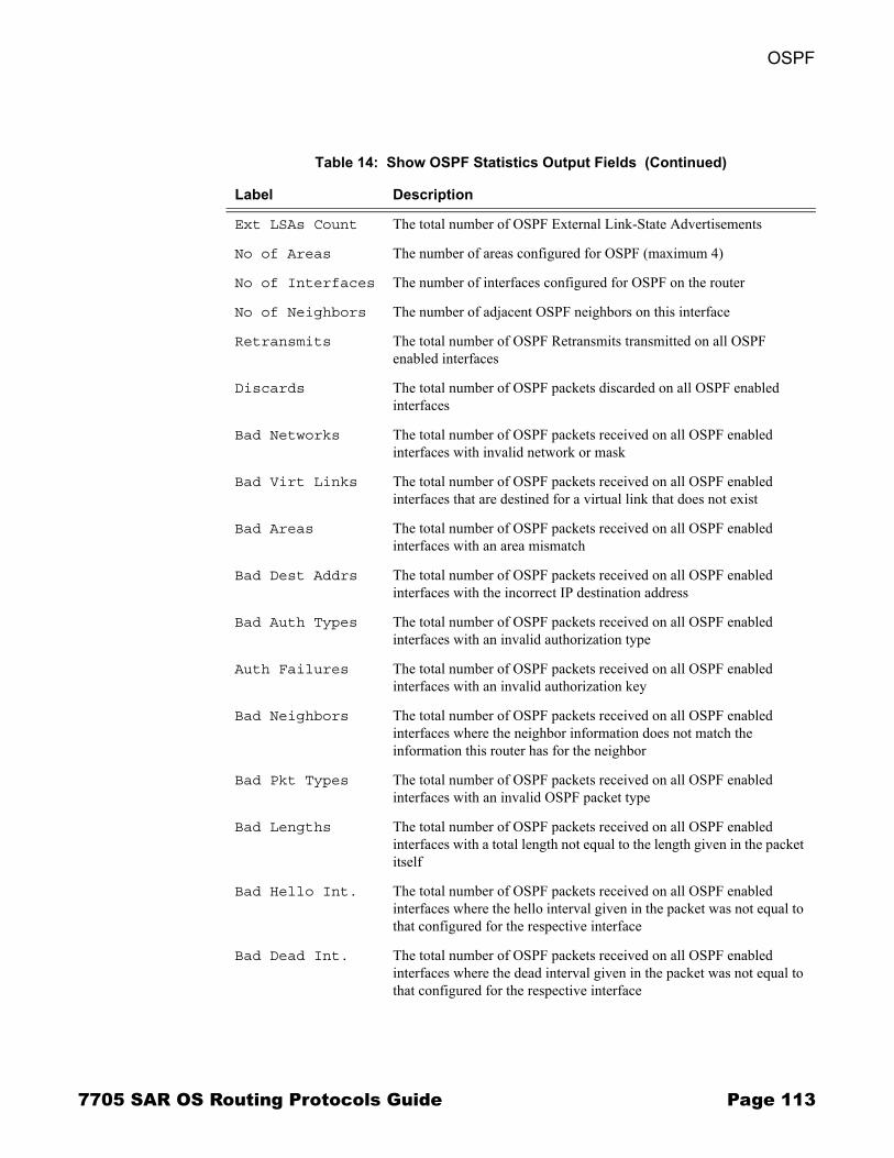
OSPF
Ext LSAs Count The total number of OSPF External Link-State Advertisements
No of Areas The number of areas configured for OSPF (maximum 4)
No of Interfaces The number of interfaces configured for OSPF on the router
No of Neighbors The number of adjacent OSPF neighbors on this interface
Retransmits The total number of OSPF Retransmits transmitted on all OSPF enabled interfaces
Discards The total number of OSPF packets discarded on all OSPF enabled interfaces
Bad Networks The total number of OSPF packets received on all OSPF enabled interfaces with invalid network or mask
Bad Virt Links The total number of OSPF packets received on all OSPF enabled interfaces that are destined for a virtual link that does not exist
Bad Areas The total number of OSPF packets received on all OSPF enabled interfaces with an area mismatch
Bad Dest Addrs The total number of OSPF packets received on all OSPF enabled interfaces with the incorrect IP destination address
Bad Auth Types The total number of OSPF packets received on all OSPF enabled interfaces with an invalid authorization type
Auth Failures The total number of OSPF packets received on all OSPF enabled interfaces with an invalid authorization key
Bad Neighbors The total number of OSPF packets received on all OSPF enabled interfaces where the neighbor information does not match the information this router has for the neighbor
Bad Pkt Types The total number of OSPF packets received on all OSPF enabled interfaces with an invalid OSPF packet type
Bad Lengths The total number of OSPF packets received on all OSPF enabled interfaces with a total length not equal to the length given in the packet itself
Bad Hello Int. The total number of OSPF packets received on all OSPF enabled interfaces where the hello interval given in the packet was not equal to that configured for the respective interface
Bad Dead Int. The total number of OSPF packets received on all OSPF enabled interfaces where the dead interval given in the packet was not equal to that configured for the respective interface
Table 14: Show OSPF Statistics Output Fields (Continued)
Label Description
7705 SAR OS Routing Protocols Guide Page 113
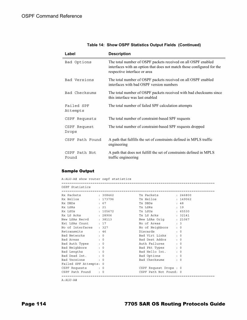
OSPF Command Reference
Sample Output
A:ALU-A# show router ospf statistics===============================================================================OSPF Statistics===============================================================================Rx Packets : 308462 Tx Packets : 246800Rx Hellos : 173796 Tx Hellos : 149062Rx DBDs : 67 Tx DBDs : 48Rx LSRs : 21 Tx LSRs : 19Rx LSUs : 105672 Tx LSUs : 65530Rx LS Acks : 28906 Tx LS Acks : 32141New LSAs Recvd : 38113 New LSAs Orig : 21067Ext LSAs Count : 17 No of Areas : 3No of Interfaces : 327 No of Neighbors : 0Retransmits : 46 Discards : 0Bad Networks : 0 Bad Virt Links : 0Bad Areas : 0 Bad Dest Addrs : 0Bad Auth Types : 0 Auth Failures : 0Bad Neighbors : 0 Bad Pkt Types : 0Bad Lengths : 0 Bad Hello Int. : 0Bad Dead Int. : 0 Bad Options : 0Bad Versions : 0 Bad Checksums : 0Failed SPF Attempts: 0CSPF Requests : 0 CSPF Request Drops : 0CSPF Path Found : 0 CSPF Path Not Found: 0===============================================================================A:ALU-A#
Bad Options The total number of OSPF packets received on all OSPF enabled interfaces with an option that does not match those configured for the respective interface or area
Bad Versions The total number of OSPF packets received on all OSPF enabled interfaces with bad OSPF version numbers
Bad Checksums The total number of OSPF packets received with bad checksums since this interface was last enabled
Failed SPF Attempts
The total number of failed SPF calculation attempts
CSPF Requests The total number of constraint-based SPF requests
CSPF Request Drops
The total number of constraint-based SPF requests dropped
CSPF Path Found A path that fulfills the set of constraints defined in MPLS traffic engineering
CSPF Path Not Found
A path that does not fulfill the set of constraints defined in MPLS traffic engineering
Table 14: Show OSPF Statistics Output Fields (Continued)
Label Description
Page 114 7705 SAR OS Routing Protocols Guide
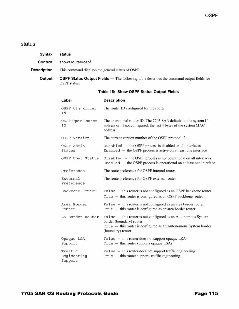
OSPF
status
Syntax status
Context show>router>ospf
Description This command displays the general status of OSPF.
Output OSPF Status Output Fields � The following table describes the command output fields for OSPF status.
Table 15: Show OSPF Status Output Fields
Label Description
OSPF Cfg Router Id
The router ID configured for the router
OSPF Oper Router ID
The operational router ID. The 7705 SAR defaults to the system IP address or, if not configured, the last 4 bytes of the system MAC address.
OSPF Version The current version number of the OSPF protocol: 2
OSPF Admin Status
Disabled — the OSPF process is disabled on all interfacesEnabled — the OSPF process is active on at least one interface
OSPF Oper Status Disabled — the OSPF process is not operational on all interfacesEnabled — the OSPF process is operational on at least one interface
Preference The route preference for OSPF internal routes
External Preference
The route preference for OSPF external routes
Backbone Router False — this router is not configured as an OSPF backbone routerTrue — this router is configured as an OSPF backbone router
Area Border Router
False — this router is not configured as an area border routerTrue — this router is configured as an area border router
AS Border Router False — this router is not configured as an Autonomous System border (boundary) routerTrue — this router is configured as an Autonomous System border (boundary) router
Opaque LSA Support
False — this router does not support opaque LSAsTrue — this router supports opaque LSAs
Traffic Engineering Support
False — this router does not support traffic engineeringTrue — this router supports traffic engineering
7705 SAR OS Routing Protocols Guide Page 115
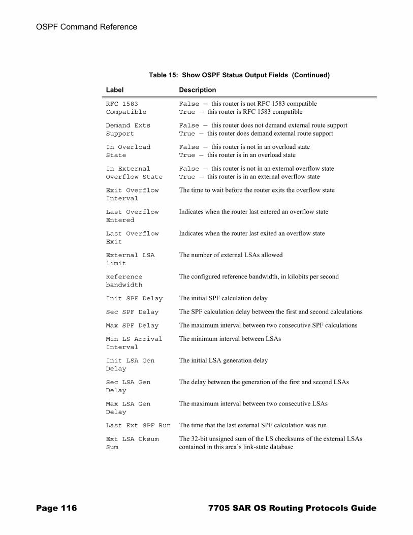
OSPF Command Reference
RFC 1583 Compatible
False — this router is not RFC 1583 compatibleTrue — this router is RFC 1583 compatible
Demand Exts Support
False — this router does not demand external route supportTrue — this router does demand external route support
In Overload State
False — this router is not in an overload stateTrue — this router is in an overload state
In External Overflow State
False — this router is not in an external overflow stateTrue — this router is in an external overflow state
Exit Overflow Interval
The time to wait before the router exits the overflow state
Last Overflow Entered
Indicates when the router last entered an overflow state
Last Overflow Exit
Indicates when the router last exited an overflow state
External LSA limit
The number of external LSAs allowed
Reference bandwidth
The configured reference bandwidth, in kilobits per second
Init SPF Delay The initial SPF calculation delay
Sec SPF Delay The SPF calculation delay between the first and second calculations
Max SPF Delay The maximum interval between two consecutive SPF calculations
Min LS Arrival Interval
The minimum interval between LSAs
Init LSA Gen Delay
The initial LSA generation delay
Sec LSA Gen Delay
The delay between the generation of the first and second LSAs
Max LSA Gen Delay
The maximum interval between two consecutive LSAs
Last Ext SPF Run The time that the last external SPF calculation was run
Ext LSA Cksum Sum
The 32-bit unsigned sum of the LS checksums of the external LSAs contained in this area�s link-state database
Table 15: Show OSPF Status Output Fields (Continued)
Label Description
Page 116 7705 SAR OS Routing Protocols Guide
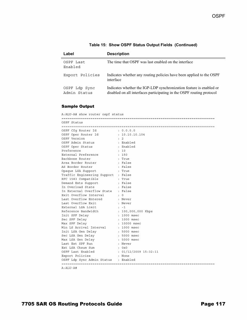
OSPF
Sample Output
A:ALU-A# show router ospf status===============================================================================OSPF Status===============================================================================OSPF Cfg Router Id : 0.0.0.0OSPF Oper Router Id : 10.10.10.104OSPF Version : 2OSPF Admin Status : EnabledOSPF Oper Status : EnabledPreference : 10External Preference : 150Backbone Router : TrueArea Border Router : FalseAS Border Router : FalseOpaque LSA Support : TrueTraffic Engineering Support : FalseRFC 1583 Compatible : TrueDemand Exts Support : FalseIn Overload State : FalseIn External Overflow State : FalseExit Overflow Interval : 0Last Overflow Entered : NeverLast Overflow Exit : NeverExternal LSA Limit : -1Reference Bandwidth : 100,000,000 KbpsInit SPF Delay : 1000 msecSec SPF Delay : 1000 msecMax SPF Delay : 10000 msecMin LS Arrival Interval : 1000 msecInit LSA Gen Delay : 5000 msecSec LSA Gen Delay : 5000 msecMax LSA Gen Delay : 5000 msecLast Ext SPF Run : NeverExt LSA Cksum Sum : 0x0OSPF Last Enabled : 01/12/2009 15:32:11Export Policies : NoneOSPF Ldp Sync Admin Status : Enabled===============================================================================A:ALU-A#
OSPF Last Enabled
The time that OSPF was last enabled on the interface
Export Policies Indicates whether any routing policies have been applied to the OSPF interface
OSPF Ldp Sync Admin Status
Indicates whether the IGP-LDP synchronization feature is enabled or disabled on all interfaces participating in the OSPF routing protocol
Table 15: Show OSPF Status Output Fields (Continued)
Label Description
7705 SAR OS Routing Protocols Guide Page 117
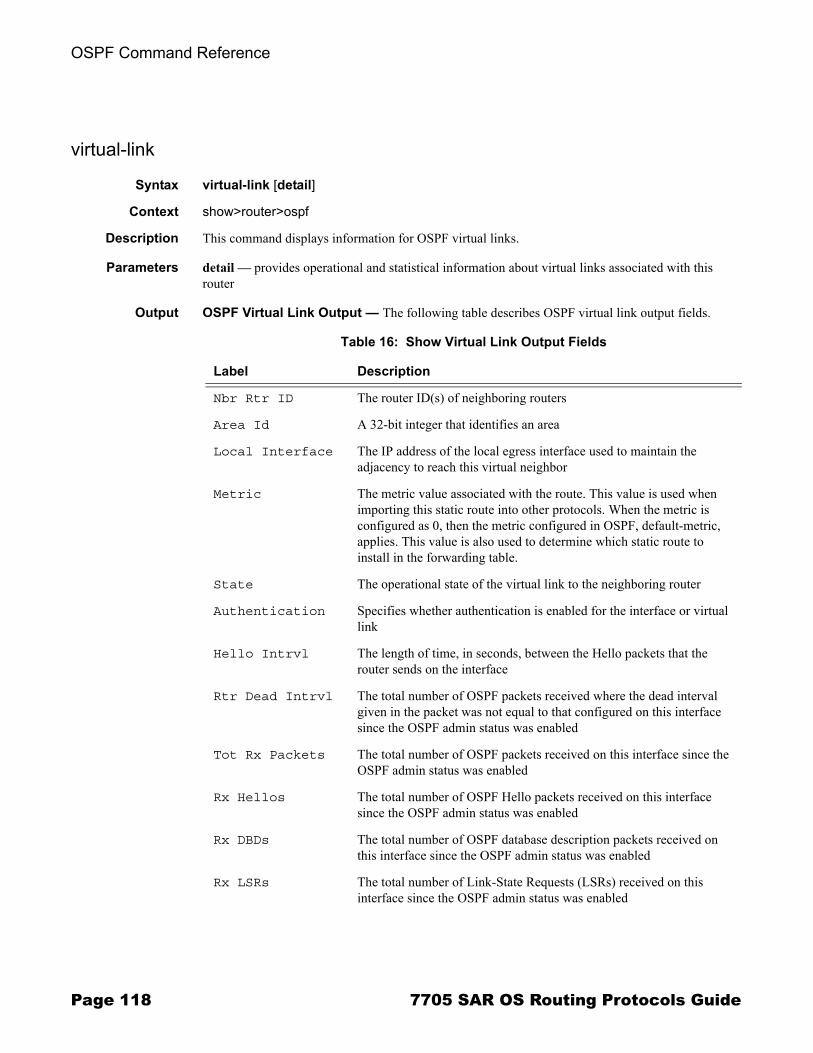
OSPF Command Reference
virtual-link
Syntax virtual-link [detail]
Context show>router>ospf
Description This command displays information for OSPF virtual links.
Parameters detail � provides operational and statistical information about virtual links associated with this router
Output OSPF Virtual Link Output � The following table describes OSPF virtual link output fields.
Table 16: Show Virtual Link Output Fields
Label Description
Nbr Rtr ID The router ID(s) of neighboring routers
Area Id A 32-bit integer that identifies an area
Local Interface The IP address of the local egress interface used to maintain the adjacency to reach this virtual neighbor
Metric The metric value associated with the route. This value is used when importing this static route into other protocols. When the metric is configured as 0, then the metric configured in OSPF, default-metric, applies. This value is also used to determine which static route to install in the forwarding table.
State The operational state of the virtual link to the neighboring router
Authentication Specifies whether authentication is enabled for the interface or virtual link
Hello Intrvl The length of time, in seconds, between the Hello packets that the router sends on the interface
Rtr Dead Intrvl The total number of OSPF packets received where the dead interval given in the packet was not equal to that configured on this interface since the OSPF admin status was enabled
Tot Rx Packets The total number of OSPF packets received on this interface since the OSPF admin status was enabled
Rx Hellos The total number of OSPF Hello packets received on this interface since the OSPF admin status was enabled
Rx DBDs The total number of OSPF database description packets received on this interface since the OSPF admin status was enabled
Rx LSRs The total number of Link-State Requests (LSRs) received on this interface since the OSPF admin status was enabled
Page 118 7705 SAR OS Routing Protocols Guide

OSPF
Rx LSUs The total number of Link-State Updates (LSUs) received on this interface since the OSPF admin status was enabled
Rx LS Acks The total number of Link-State Acknowledgements received on this interface since the OSPF admin status was enabled
Tot Tx Packets The total number of OSPF packets transmitted on this interface since the OSPF admin status was enabled
Tx Hellos The total number of OSPF Hello packets transmitted on this interface since the OSPF admin status was enabled
Tx DBDs The total number of OSPF database description packets transmitted on this interface since the OSPF admin status was enabled
Tx LSRs The total number of OSPF Link-State Requests (LSRs) transmitted on this interface since the OSPF admin status was enabled
Tx LSUs The total number of OSPF Hello packets transmitted on this interface since the OSPF admin status was enabled
Tx LS Acks The total number of OSPF Link-State Acknowledgements transmitted on this interface since the OSPF admin status was enabled
Retransmits The total number of OSPF retransmits sent on this interface since the OSPF admin status was last enabled
Discards The total number of OSPF packets discarded on this interface since the OSPF admin status was last enabled
Bad Networks The total number of OSPF packets received with invalid network or mask since the OSPF admin status was last enabled
Bad Versions The total number of OSPF packets received with bad OSPF version numbers since the OSPF admin status was last enabled
Bad Areas The total number of OSPF packets received with an area mismatch since the OSPF admin status was last enabled
Bad Dest Addrs The total number of OSPF packets received with the incorrect IP destination address since the OSPF admin status was last enabled
Bad Auth Types The total number of OSPF packets received with an invalid authorization type since the OSPF admin status was last enabled
Auth Failures The total number of OSPF packets received with an invalid authorization key since the OSPF admin status was last enabled
Bad Neighbors The total number of OSPF packets received where the neighbor information does not match the information this router has for the neighbor since the OSPF admin status was last enabled
Table 16: Show Virtual Link Output Fields (Continued)
Label Description
7705 SAR OS Routing Protocols Guide Page 119
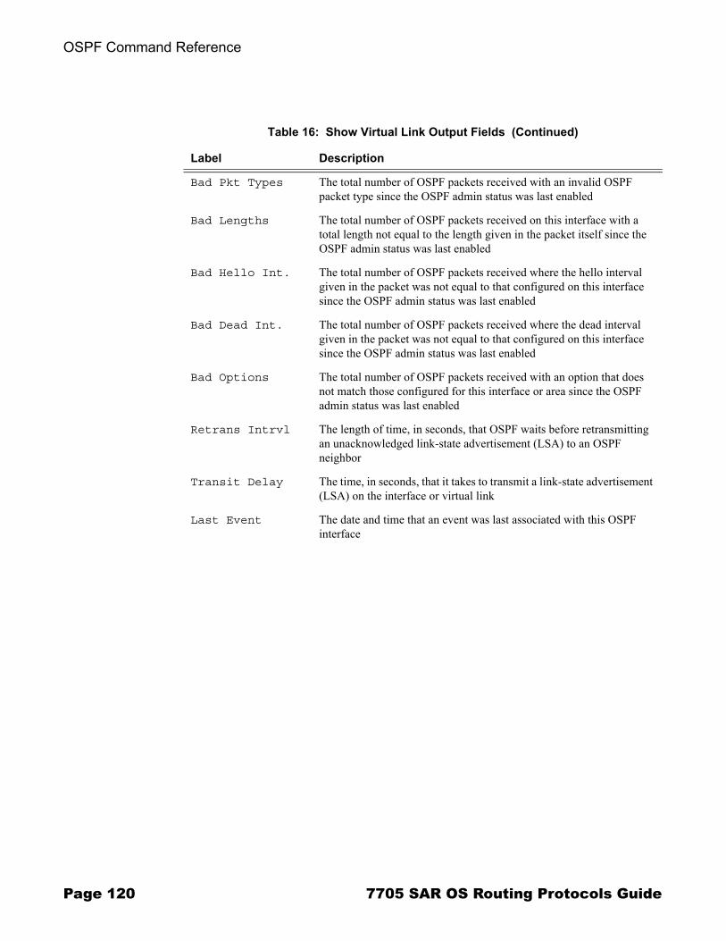
OSPF Command Reference
Bad Pkt Types The total number of OSPF packets received with an invalid OSPF packet type since the OSPF admin status was last enabled
Bad Lengths The total number of OSPF packets received on this interface with a total length not equal to the length given in the packet itself since the OSPF admin status was last enabled
Bad Hello Int. The total number of OSPF packets received where the hello interval given in the packet was not equal to that configured on this interface since the OSPF admin status was last enabled
Bad Dead Int. The total number of OSPF packets received where the dead interval given in the packet was not equal to that configured on this interface since the OSPF admin status was last enabled
Bad Options The total number of OSPF packets received with an option that does not match those configured for this interface or area since the OSPF admin status was last enabled
Retrans Intrvl The length of time, in seconds, that OSPF waits before retransmitting an unacknowledged link-state advertisement (LSA) to an OSPF neighbor
Transit Delay The time, in seconds, that it takes to transmit a link-state advertisement (LSA) on the interface or virtual link
Last Event The date and time that an event was last associated with this OSPF interface
Table 16: Show Virtual Link Output Fields (Continued)
Label Description
Page 120 7705 SAR OS Routing Protocols Guide
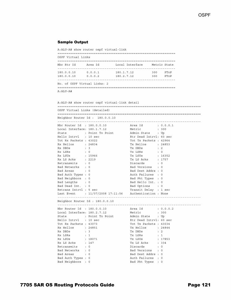
OSPF
Sample Output
A:ALU-A# show router ospf virtual-link=================================================================OSPF Virtual Links=================================================================Nbr Rtr Id Area Id Local Interface Metric State-----------------------------------------------------------------180.0.0.10 0.0.0.1 180.1.7.12 300 PToP180.0.0.10 0.0.0.2 180.2.7.12 300 PToP-----------------------------------------------------------------No. of OSPF Virtual Links: 2=================================================================A:ALU-A#
A:ALU-A# show router ospf virtual-link detail===============================================================================OSPF Virtual Links (detailed)===============================================================================Neighbor Router Id : 180.0.0.10-------------------------------------------------------------------------------Nbr Router Id : 180.0.0.10 Area Id : 0.0.0.1Local Interface: 180.1.7.12 Metric : 300State : Point To Point Admin State : UpHello Intrvl : 10 sec Rtr Dead Intrvl: 60 secTot Rx Packets : 43022 Tot Tx Packets : 42964Rx Hellos : 24834 Tx Hellos : 24853Rx DBDs : 3 Tx DBDs : 2Rx LSRs : 0 Tx LSRs : 0Rx LSUs : 15966 Tx LSUs : 16352Rx LS Acks : 2219 Tx LS Acks : 1757Retransmits : 0 Discards : 0Bad Networks : 0 Bad Versions : 0Bad Areas : 0 Bad Dest Addrs : 0Bad Auth Types : 0 Auth Failures : 0Bad Neighbors : 0 Bad Pkt Types : 0Bad Lengths : 0 Bad Hello Int. : 0Bad Dead Int. : 0 Bad Options : 0Retrans Intrvl : 5 sec Transit Delay : 1 secLast Event : 11/07/2008 17:11:56 Authentication : None-------------------------------------------------------------------------------Neighbor Router Id : 180.0.0.10-------------------------------------------------------------------------------Nbr Router Id : 180.0.0.10 Area Id : 0.0.0.2Local Interface: 180.2.7.12 Metric : 300State : Point To Point Admin State : UpHello Intrvl : 10 sec Rtr Dead Intrvl: 60 secTot Rx Packets : 43073 Tot Tx Packets : 43034Rx Hellos : 24851 Tx Hellos : 24844Rx DBDs : 3 Tx DBDs : 2Rx LSRs : 1 Tx LSRs : 1Rx LSUs : 18071 Tx LSUs : 17853Rx LS Acks : 147 Tx LS Acks : 334Retransmits : 0 Discards : 0Bad Networks : 0 Bad Versions : 0Bad Areas : 0 Bad Dest Addrs : 0Bad Auth Types : 0 Auth Failures : 0Bad Neighbors : 0 Bad Pkt Types : 0
7705 SAR OS Routing Protocols Guide Page 121
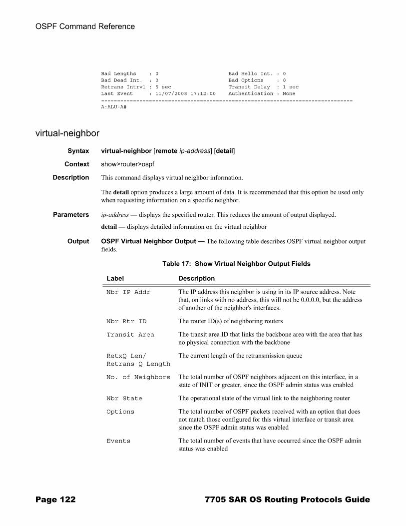
OSPF Command Reference
Bad Lengths : 0 Bad Hello Int. : 0Bad Dead Int. : 0 Bad Options : 0Retrans Intrvl : 5 sec Transit Delay : 1 secLast Event : 11/07/2008 17:12:00 Authentication : None===============================================================================A:ALU-A#
virtual-neighbor
Syntax virtual-neighbor [remote ip-address] [detail]
Context show>router>ospf
Description This command displays virtual neighbor information.
The detail option produces a large amount of data. It is recommended that this option be used only when requesting information on a specific neighbor.
Parameters ip-address � displays the specified router. This reduces the amount of output displayed.
detail � displays detailed information on the virtual neighbor
Output OSPF Virtual Neighbor Output � The following table describes OSPF virtual neighbor output fields.
Table 17: Show Virtual Neighbor Output Fields
Label Description
Nbr IP Addr The IP address this neighbor is using in its IP source address. Note that, on links with no address, this will not be 0.0.0.0, but the address of another of the neighbor's interfaces.
Nbr Rtr ID The router ID(s) of neighboring routers
Transit Area The transit area ID that links the backbone area with the area that has no physical connection with the backbone
RetxQ Len/ Retrans Q Length
The current length of the retransmission queue
No. of Neighbors The total number of OSPF neighbors adjacent on this interface, in a state of INIT or greater, since the OSPF admin status was enabled
Nbr State The operational state of the virtual link to the neighboring router
Options The total number of OSPF packets received with an option that does not match those configured for this virtual interface or transit area since the OSPF admin status was enabled
Events The total number of events that have occurred since the OSPF admin status was enabled
Page 122 7705 SAR OS Routing Protocols Guide
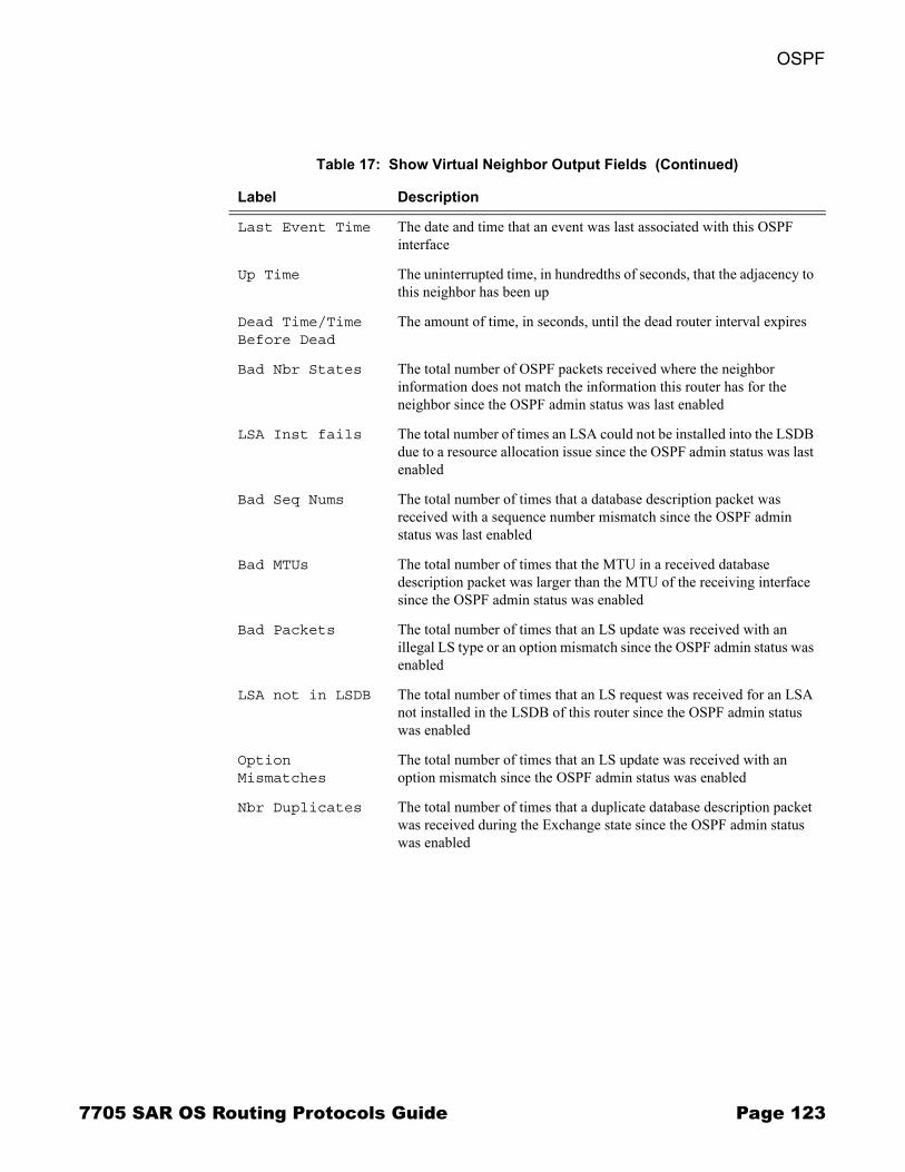
OSPF
Last Event Time The date and time that an event was last associated with this OSPF interface
Up Time The uninterrupted time, in hundredths of seconds, that the adjacency to this neighbor has been up
Dead Time/Time Before Dead
The amount of time, in seconds, until the dead router interval expires
Bad Nbr States The total number of OSPF packets received where the neighbor information does not match the information this router has for the neighbor since the OSPF admin status was last enabled
LSA Inst fails The total number of times an LSA could not be installed into the LSDB due to a resource allocation issue since the OSPF admin status was last enabled
Bad Seq Nums The total number of times that a database description packet was received with a sequence number mismatch since the OSPF admin status was last enabled
Bad MTUs The total number of times that the MTU in a received database description packet was larger than the MTU of the receiving interface since the OSPF admin status was enabled
Bad Packets The total number of times that an LS update was received with an illegal LS type or an option mismatch since the OSPF admin status was enabled
LSA not in LSDB The total number of times that an LS request was received for an LSA not installed in the LSDB of this router since the OSPF admin status was enabled
Option Mismatches
The total number of times that an LS update was received with an option mismatch since the OSPF admin status was enabled
Nbr Duplicates The total number of times that a duplicate database description packet was received during the Exchange state since the OSPF admin status was enabled
Table 17: Show Virtual Neighbor Output Fields (Continued)
Label Description
7705 SAR OS Routing Protocols Guide Page 123
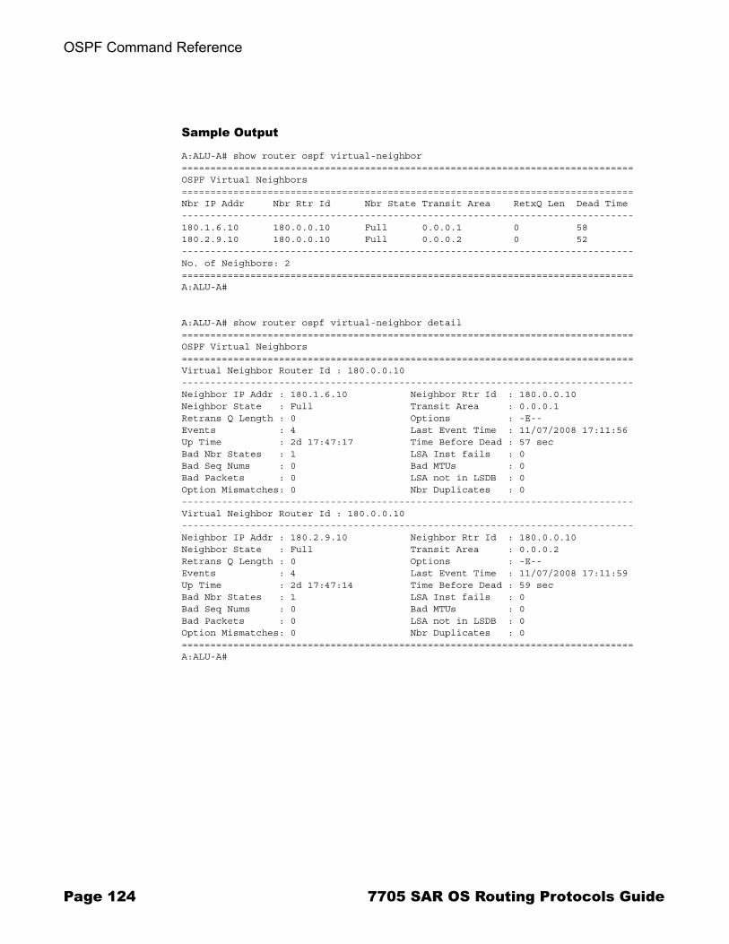
OSPF Command Reference
Sample Output
A:ALU-A# show router ospf virtual-neighbor===============================================================================OSPF Virtual Neighbors===============================================================================Nbr IP Addr Nbr Rtr Id Nbr State Transit Area RetxQ Len Dead Time-------------------------------------------------------------------------------180.1.6.10 180.0.0.10 Full 0.0.0.1 0 58180.2.9.10 180.0.0.10 Full 0.0.0.2 0 52-------------------------------------------------------------------------------No. of Neighbors: 2===============================================================================A:ALU-A#
A:ALU-A# show router ospf virtual-neighbor detail===============================================================================OSPF Virtual Neighbors===============================================================================Virtual Neighbor Router Id : 180.0.0.10-------------------------------------------------------------------------------Neighbor IP Addr : 180.1.6.10 Neighbor Rtr Id : 180.0.0.10Neighbor State : Full Transit Area : 0.0.0.1Retrans Q Length : 0 Options : -E--Events : 4 Last Event Time : 11/07/2008 17:11:56Up Time : 2d 17:47:17 Time Before Dead : 57 secBad Nbr States : 1 LSA Inst fails : 0Bad Seq Nums : 0 Bad MTUs : 0Bad Packets : 0 LSA not in LSDB : 0Option Mismatches: 0 Nbr Duplicates : 0-------------------------------------------------------------------------------Virtual Neighbor Router Id : 180.0.0.10-------------------------------------------------------------------------------Neighbor IP Addr : 180.2.9.10 Neighbor Rtr Id : 180.0.0.10Neighbor State : Full Transit Area : 0.0.0.2Retrans Q Length : 0 Options : -E--Events : 4 Last Event Time : 11/07/2008 17:11:59Up Time : 2d 17:47:14 Time Before Dead : 59 secBad Nbr States : 1 LSA Inst fails : 0Bad Seq Nums : 0 Bad MTUs : 0Bad Packets : 0 LSA not in LSDB : 0Option Mismatches: 0 Nbr Duplicates : 0===============================================================================A:ALU-A#
Page 124 7705 SAR OS Routing Protocols Guide
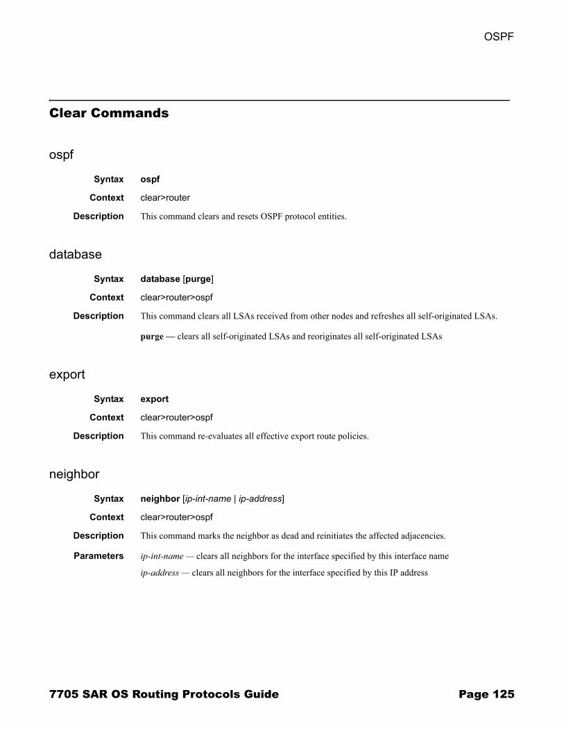
OSPF
Clear Commands
ospf
Syntax ospf
Context clear>router
Description This command clears and resets OSPF protocol entities.
database
Syntax database [purge]
Context clear>router>ospf
Description This command clears all LSAs received from other nodes and refreshes all self-originated LSAs.
purge � clears all self-originated LSAs and reoriginates all self-originated LSAs
export
Syntax export
Context clear>router>ospf
Description This command re-evaluates all effective export route policies.
neighbor
Syntax neighbor [ip-int-name | ip-address]
Context clear>router>ospf
Description This command marks the neighbor as dead and reinitiates the affected adjacencies.
Parameters ip-int-name � clears all neighbors for the interface specified by this interface name
ip-address � clears all neighbors for the interface specified by this IP address
7705 SAR OS Routing Protocols Guide Page 125
OSPF Command Reference
statistics
Syntax statistics
Context clear>router>ospf
Description This command clears all neighbor, router, interface, SPF, and global statistics for OSPF.
Page 126 7705 SAR OS Routing Protocols Guide

OSPF
Debug Commands
ospf
Syntax ospf
Context debug>router
Description This command enables the context for OSPF debugging purposes.
area
Syntax area [area-id]no area
Context debug>router>ospf
Description This command enables debugging for an OSPF area.
Parameters area-id � the OSPF area ID expressed in dotted-decimal notation or as a 32-bit decimal integer
area-range
Syntax area-range [ip-address]no area-range
Context debug>router>ospf
Description This command enables debugging for an OSPF area range.
Parameters ip-address � the IP address for the range used by the ABR to advertise into another area
cspf
Syntax cspf [ip-address]no cspf
Context debug>router>ospf
Description This command enables debugging for an OSPF constraint-based shortest path first (CSPF).
Parameters ip-address � the IP address for the range used for CSPF
7705 SAR OS Routing Protocols Guide Page 127
OSPF Command Reference
interface
Syntax interface [ip-int-name | ip-address]no interface
Context debug>router>ospf
Description This command enables debugging for an OSPF interface.
Parameters ip-int-name � the IP interface name. An interface name cannot be in the form of an IP address. Interface names can be any string up to 32 characters long composed of printable, 7-bit ASCII characters. If the string contains special characters (#, $, spaces, etc.), the entire string must be enclosed within double quotes.
ip-address � the interface�s IP address
leak
Syntax leak [ip-address]no leak
Context debug>router>ospf
Description This command enables debugging for OSPF leaks.
Parameters ip-address � the IP address to debug OSPF leaks
lsdb
Syntax lsdb [type] [ls-id] [adv-rtr-id] [area area-id]no lsdb
Context debug>router>ospf
Description This command enables debugging for an OSPF link-state database.
Parameters type � the OSPF link-state database type
Values router, network, summary, asbr, extern, nssa
ls-id � an LSA type-specific field containing either a router ID or an IP address. It identifies the piece of the routing domain being described by the advertisement.
adv-rtr-id � the router identifier of the router advertising the LSA
area-id � the OSPF area ID expressed in dotted-decimal notation or as a 32-bit decimal integer
Page 128 7705 SAR OS Routing Protocols Guide
OSPF
misc
Syntax [no] misc
Context debug>router>ospf
Description This command enables debugging for miscellaneous OSPF events.
neighbor
Syntax neighbor [ip-int-name | router-id]no neighbor
Context debug>router>ospf
Description This command enables debugging for an OSPF neighbor.
Parameters ip-int-name � the neighbor interface name
router-id � neighbor information for the neighbor identified by the the specified router ID
nssa-range
Syntax nssa-range [ip-address]no nssa-range
Context debug>router>ospf
Description This command enables debugging for an NSSA range.
Parameters ip-address � the IP address range to debug
packet
Syntax packet [packet-type] [ip-address]no packet
Context debug>router>ospf
Description This command enables debugging for OSPF packets.
Parameters packet-type � the OSPF packet type to debug
Values hello, dbdescr, lsrequest, lsupdate, lsack
ip-address � the IP address to debug
7705 SAR OS Routing Protocols Guide Page 129
OSPF Command Reference
rtm
Syntax rtm [ip-address]no rtm
Context debug>router>ospf
Description This command enables debugging for the OSPF routing table manager.
Parameters ip-address � the IP address to debug
spf
Syntax spf [type] [dest-addr]no spf
Context debug>router>ospf
Description This command enables debugging for OSPF SPF. Information regarding overall SPF start and stop times are shown. To see detailed information regarding the SPF calculation of a given route, the route must be specified as an optional argument.
Parameters type � the area to debug
Values intra-area, inter-area, external
dest-addr � the destination IP address to debug
virtual-neighbor
Syntax virtual-neighbor [ip-address]no virtual-neighbor
Context debug>router>ospf
Description This command enables debugging for an OSPF virtual neighbor.
Parameters ip-address � the IP address of the virtual neighbor
Page 130 7705 SAR OS Routing Protocols Guide
Standards and Protocol Support
Standards ComplianceIEEE 802.1p/q VLAN TaggingIEEE 802.3 10BaseTIEEE 802.3u 100BaseTXIEEE 802.3x Flow ControlIEEE 802.3z 1000BaseSX/LX
Protocol Support
ATMRFC 2514 Definitions of Textual Conventions and
OBJECT_IDENTITIES for ATM Management, February 1999
RFC 2515 Definition of Managed Objects for ATM Management, February 1999
RFC 2684 Multiprotocol Encapsulation over ATM Adaptation Layer 5
af-tm-0121.000 Traffic Management Specification Version 4.1, March 1999
ITU-T Recommendation I.610 - B-ISDN Operation and Maintenance Principles and Functions version 11/95
ITU-T Recommendation I.432.1 - B-ISDN user-network interface - Physical layer specification: General characteristics
GR-1248-CORE - Generic Requirements for Operations of ATM Network Elements (NEs). Issue 3 June 1996
GR-1113-CORE - Bellcore, Asynchronous Transfer Mode (ATM) and ATM Adaptation Layer (AAL) Protocols Generic Requirements, Issue 1, July 1994
GR-253-CORE - SONET Transport Systems: Common Generic Criteria. Issue 3, September 2000
AF-PHY-0086.001 Inverse Multiplexing for ATM (IMA)
DIFFERENTIATED SERVICESRFC 2474 Definition of the DS Field in the IPv4
and IPv6 HeadersRFC 2597 Assured Forwarding PHB GroupRFC 2598 An Expedited Forwarding PHBRFC 3140 Per-Hop Behavior Identification Codes
LDPRFC 5036 LDP Specification
MPLSRFC 3031 MPLS ArchitectureRFC 3032 MPLS Label Stack EncodingRFC 4379 Detecting Multi-Protocol Label
Switched (MPLS) Data Plane Failures
NETWORK MANAGEMENTITU-T X.721: Information technology- OSI-Structure
of Management InformationITU-T X.734: Information technology- OSI-Systems
Management: Event Report Management FunctionM.3100/3120 Equipment and Connection ModelsTMF 509/613 Network Connectivity ModelRFC 1157 SNMPv1RFC 1305 Network Time Protocol (Version 3)
Specification, Implementation and AnalysisRFC 1850 OSPF-MIBRFC 1907 SNMPv2-MIBRFC 2011 IP-MIBRFC 2012 TCP-MIBRFC 2013 UDP-MIBRFC 2030 Simple Network Time Protocol (SNTP)
Version 4 for IPv4, IPv6 and OSIRFC 2096 IP-FORWARD-MIBRFC 2138 RADIUSRFC 2206 RSVP-MIBRFC 2571 SNMP-FRAMEWORKMIBRFC 2572 SNMP-MPD-MIBRFC 2573 SNMP-TARGET-&-
NOTIFICATION-MIBRFC 2574 SNMP-USER-BASED-SMMIB
7705 SAR OS Routing Protocols Guide Page 131

Standards and Protocol Support
RFC 2575 SNMP-VIEW-BASED ACM-MIB
RFC 2576 SNMP-COMMUNITY-MIBRFC 2588 SONET-MIBRFC 2665 EtherLike-MIBRFC 2819 RMON-MIBRFC 2863 IF-MIBRFC 2864 INVERTED-STACK-MIBRFC 3014 NOTIFICATION-LOG MIBRFC 3164 The BSD Syslog ProtocolRFC 3273 HCRMON-MIBRFC 3411 An Architecture for Describing Simple
Network Management Protocol (SNMP) Management Frameworks
RFC 3412 Message Processing and Dispatching for the Simple Network Management Protocol (SNMP)
RFC 3413 Simple Network Management Protocol (SNMP) Applications
RFC 3414 User-based Security Model (USM) for version 3 of the Simple Network Management Protocol (SNMPv3)
RFC 3418 SNMP MIBdraft-ietf-disman-alarm-mib-04.txtdraft-ietf-mpls-ldp-mib-07.txtdraft-ietf-ospf-mib-update-04.txtdraft-ietf-mpls-lsr-mib-06.txtdraft-ietf-mpls-te-mib-04.txtIANA-IFType-MIB
OSPFRFC 1765 OSPF Database OverflowRFC 2328 OSPF Version 2RFC 2370 Opaque LSA SupportRFC 3101 OSPF NSSA OptionRFC 3630 Traffic Engineering (TE) Extensions to
OSPF
PPPRFC 1332 PPP IPCP RFC 1661 PPPRFC 1662 PPP in HDLC-like FramingRFC 1989 PPP Link Quality MonitoringRFC 1990 The PPP Multilink Protocol (MP)
PSEUDOWIRESRFC 3985 Pseudo Wire Emulation Edge-to-Edge
(PWE3) ArchitectureRFC 4385 Pseudowire Emulation Edge-to-Edge
(PWE3) Control Word for Use over an MPLS PSN
RFC 4446 IANA Allocation for PWE3RFC 4447 Pseudowire Setup and Maintenance
Using the Label Distribution Protocol (LDP)RFC 4448 Encapsulation Methods for Transport of
Ethernet over MPLS NetworksRFC 4553 Structure-Agnostic Time Division
Multiplexing (TDM) over Packet (SAToP)RFC 4717 Encapsulation Methods for Transport of
Asynchronous Transfer Mode (ATM) over MPLS Networks
RFC 5086 Structure-Aware Time Division Multiplexed (TDM) Circuit Emulation Service over Packet Switched Network (CESoPSN)
RFC 5085 Pseudowire Virtual Circuit Connectivity Verification (VCCV): A Control Channel for Pseudowires
draft-ietf-pwe3-redundancy-01 Pseudowire (PW) Redundancy
RADIUSRFC 2865 Remote Authentication Dial In User
ServiceRFC 2866 RADIUS Accounting
RSVP-TE and FRRRFC 2430 A Provider Architecture for DiffServ &
TERFC 2961 RSVP Refresh Overhead Reduction
ExtensionsRFC 3209 Extensions to RSVP for LSP TunnelsRFC 3210 Applicability Statement for Extensions
to RSVP for LSP TunnelsRFC 4090 Fast Reroute Extensions to RSVP-TE for
LSP Tunnels
SONET/SDHGR-253-CORE SONET Transport Systems: Common
Generic Criteria. Issue 3, September 2000ITU-G.841 Telecommunication Standardization
Section of ITU, Types and Characteristics of SDH Networks Protection Architecture, issued in October 1998 and as augmented by Corrigendum1 issued in July 2002
GR-253-CORE - SONET Transport Systems: Common Generic Criteria. Issue 3, September 2000
Page 132 7705 SAR OS Routing Protocols Guide
Standards and Protocol Support
SSHdraft-ietf-secsh-architecture.txt SSH Protocol
Architecturedraft-ietf-secsh-userauth.txt SSH Authentication
Protocoldraft-ietf-secsh-transport.txt SSH Transport Layer
Protocoldraft-ietf-secsh-connection.txt SSH Connection
Protocoldraft-ietf-secsh- newmodes.txt SSH Transport Layer
Encryption Modes
SYNCHRONIZATIONG.813 Timing characteristics of SDH equipment slave
clocks (SEC)G.8261 Timing and synchronization aspects in packet
networksG.8262 Timing characteristics of synchronous
Ethernet equipment slave clockGR 1244 CORE Clocks for the Synchronized
Network: Common Generic Criteria
TACACS+draft-grant-tacacs-02.txt The TACACS+ Protocol
TCP/IPRFC 768 UDPRFC 791 IPRFC 792 ICMPRFC 793 TCP RFC 826 ARPRFC 854 TelnetRFC 1350 The TFTP Protocol (Rev. 2)RFC 1812 Requirements for IPv4 Routers
Proprietary MIBsTIMETRA-ATM-MIB.mibTIMETRA-CAPABILITY-7705-V1.mibTIMETRA-CFLOWD-MIB.mibTIMETRA-CHASSIS-MIB.mibTIMETRA-CLEAR-MIB.mibTIMETRA-FILTER-MIB.mibTIMETRA-GLOBAL-MIB.mibTIMETRA-LDP-MIB.mibTIMETRA-LOG-MIB.mibTIMETRA-MPLS-MIB.mibTIMETRA-OAM-TEST-MIB.mibTIMETRA-PORT-MIB.mibTIMETRA-PPP-MIB.mibTIMETRA-QOS-MIB.mibTIMETRA-ROUTE-POLICY-MIB.mibTIMETRA-SAP-MIB.mibTIMETRA-SDP-MIB.mibTIMETRA-SECURITY-MIB.mibTIMETRA-SERV-MIB.mibTIMETRA-SYSTEM-MIB.mibTIMETRA-TC-MIB.mib
7705 SAR OS Routing Protocols Guide Page 133
Standards and Protocol Support
Page 134 7705 SAR OS Routing Protocols Guide

Customer documentation and product support
Customer documentationhttp://www.alcatel-lucent.com/myaccessProduct manuals and documentation updates are available at alcatel-lucent.com. If you are a new user and require access to this service, please contact your Alcatel-Lucent sales representative.
Technical Supporthttp://www.alcatel-lucent.com/support
Documentation [email protected]

© 2009 Alcatel-Lucent. All rights reserved.3HE 04681 AAAA TQZZA Edition 01