Embed Size (px)
Citation preview

7.4.1 Student Book © 2005 Propane Education & Research Council Page 1
7.4.1
Identifying the Operating Characteristics of Circuit
Control Devices, Electromagnetic Devices &
Transformers Understanding control circuits and how their components manage electrical current flow is essential to serving gas appliances In this module, you will learn to:
1. Gas appliance operating systems
2. The operating characteristics of circuits, devices and symbols
3. Electromagnetic controls
4. Electromagnetic induction
5. Alternating current
6. Transformers

7.4.1 Student Book © 2005 Propane Education & Research Council Page 1
Identifying Gas Appliance Operating Systems
In order to troubleshoot a gas appliance system, it is necessary to apply a thorough understanding of the devices that control the appliance, an understanding of the way electrical circuits are used to operate the devices, and the ability to think of the appliance as a system made up of smaller systems. Figure 1. Simple Sequence of Operation Flow Chart
He a t Tra nsfe r
Fo rc e d Air Blo we r/Duc ts Hyd ronic
Pum p s/Pip ingRa d ia to rs
The rm o sta t (Te m p . O p e ra ting C o ntro l)
Burne r
Ve ntingSyste m
Ig n itio n Syste m (Sa fe ty & O p e ra ting C o nt.)
Burne rC o ntro l
(Ignition Control Module)
(Gas Valve)
(Flame Rectifying Igniter)

7.4.1 Student Book © 2005 Propane Education & Research Council Page 2
The trouble shooting logic to use in gas-fired appliance manipulation follows a sequence-of-operation method. Figure 1 is a graphic that shows the general sequence-of-operation for an appliance. The operating sequence starts at the:
(1) Thermostat which responds to a drop in temperature by sending a call for heat signal to the Ignition System.
(2) In turn, the Ignition Control Module sends a signal to the
(3) Burner Control Valve to first light the pilot burner, and after receiving an ignition signal, to then open the main burner valve.
(4) The Venting System (draft fan pressure switch) confirms that the products of combustion are being properly conducted out of the building and verifies that the burner can continue operating.
(5) As heat is transferred from the appliance to the building, the heat acts on the
(6) Thermostat to end the call for heat.

7.4.1 Student Book © 2005 Propane Education & Research Council Page 2
The operating sequence begins and ends at the thermostat. The electrical circuits manage the operating functions that are required to complete the call for heat sequence and then shutdown the appliance when it is completed.
The appliance is an operating system made up of a number of smaller systems which work together in a controlled way to produce the desired results in a safe manner. This training module examines particular controls and devices which must be understood in order for you to successfully
1. read circuit diagrams2. troubleshooting flow charts, and3. to apply proven troubleshooting methods.
7.4.1 Student Book © 2005 Propane Education & Research Council Pages 2 & 3
Identifying the operating characteristics of circuits, devices andtheir diagram symbols
Figure 2. Ladder Diagram(Control Circuit—Bottom Section)
Circuits. Consider each rung of the ladder diagram as a complete circuit for a "working" component and its control.
The working component converts electricity to some useful function. It could be a motor, heater element, light, solenoid, etc. The controlling unit or switch turns the working component on or off.
In this discussion, controls in a circuit will be classified as operating or safety controls.

7.4.1 Student Book © 2005 Propane Education & Research Council Page 3
An operating control turns a working component on or off.
A safety control automatically turns a working component or the entire system off in case of a malfunction or abnormal operating condition.
The three essential elements of each circuit are:
1. Component(s) that perform work (such as a blower fan or the burner)
2. Component(s) which control (relays, switches, valves, and electronic control modules)
3. Connecting wiring conveying electricity to the components in the circuit.

7.4.1 Student Book © 2005 Propane Education & Research Council Page 4
Circuit Devices
Figure 3. InterlockSwitch Symbol
Safety Interlock Switch. Figure 3. illustrates a safety interlock switch.
This is also indicated in the circuit illustrated in Figure 2, page 3.
A safety interlock switch is placed in the circuit to prevent the equipment from being operated in an unsafe condition.
As used in the furnace diagramed in Figure 2, the interlock switch will open the circuit if a door on the equipment is open or if a panel designed to protect the operator is removed.
7.4.1 Student Book © 2005 Propane Education & Research Council Page 4
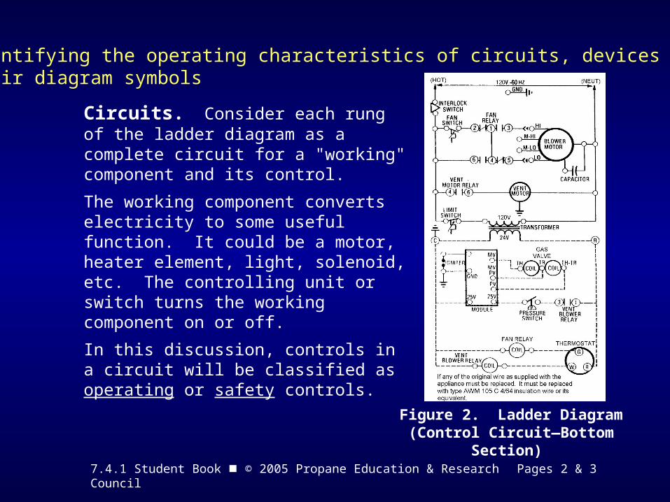
• Fan control
• Limit control
• Rollout switch
• Flue limit
Temperature Actuated Switches are used in the circuit illustrated in Figure 2, page 3, as follows:
(N/O) Normally (N/C) NormallyOpen Contact Closed Contact
Figure 4. Symbols for Temperature Activated Switches

7.4.1 Student Book © 2005 Propane Education & Research Council Page 5
Figure 5. Combination Limit/Fan Control
The main function of the limit/fan control switch is to monitor the heating system and activate the fan or blower, after sufficient heat is available for distribution.
Most fan controls are constructed of a normally open (N/O) single pole/single throw (SP/ST) heat- sensitive electrical switch.
The N/O contacts close at a set temperature and complete the electrical circuit to the fan or blower.

7.4.1 Student Book © 2005 Propane Education & Research Council Page 5
The function of a rollout switch is to monitor the combustion chamber for flame rollout.
A flue limit switch monitors the flue temperature. It interrupts the operation of the heat source in the event the flue is not accepting the products of combustion properly and the temperature exceeds the preset temperature of the flue limit switch.

7.4.1 Student Book © 2005 Propane Education & Research Council Page 6
Figure 6. Draft FanPressure Switch
Pressure Switch— A diaphragm in the pressure switch responds to pressure change and moves a mechanical linkage to open or close an electrical circuit.
As the fan starts to turn, positive (+) pressure starts to build in the chamber of the power vent. The sensing tube conveys the increased pressure to the diaphragm assembly.
The pressure moves the diaphragm, closing the normally open switch, completing the 24-volt current path to the direct spark ignition (DSI), intermittent ignition device (IID) or hot surface ignition module.

7.4.1 Student Book © 2005 Propane Education & Research Council Pages 6 & 7
Relays are basically communication carriers. They are electro-mechanical devices. A relay has a plunger that moves through the opening in a coil. Contacts are connected to the plunger.
Figure 7a
Figure 7b
7.4.1 Student Book © 2005 Propane Education & Research Council Page 7
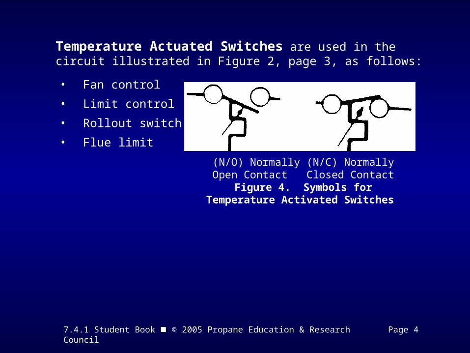
The contacts attached to the moving plunger move from a closed to an open position, or from an open to a closed position. Contacts are referred to as normally closed (N/C) or normally open (N/O) in relation to the condition of the de-energized coil. When the coil is energized, normally open (N/O) contacts close, and normally closed (N/C) contacts open.
Depending upon the situation, the contacts of a relay may be connected in one circuit and the relay coil connected in another circuit.
In Figure 8 the contacts on the fan relay are connected in the line voltage circuit (120V), and the coil is connected in the low voltage circuit (24V).
Notice the symbol for the coil for the fan relay is clearly marked.
Figure 8. Ladder Diagram
(Single Pole, Double Throw)

7.4.1 Student Book © 2005 Propane Education & Research Council Page 8
Solenoids, like the relay and contacts, are electromechanical devices. When the coil of the solenoid is energized, a magnetic field is produced around the coil. The force produced by the magnetic field acts on the solenoid plunger. Because of this force the plunger moves into the coil.
Figure 9. Pilotstat®
Power Unit
Solenoid operated valves are used extensively in gas controls. For example, Honeywell’s' Pilotstat® power unit, as illustrated in Figure 9, uses electric current (DC) generated by the thermocouple at the pilot light to hold the safety shutoff open to permit gas to flow to the main burner.

7.4.1 Student Book © 2005 Propane Education & Research Council Pages 9 & 10
Ignition Systems— Whatever the ignition system, (standing pilot, or electronic ignition) it must be capable of protecting against gas flowing to the main burner when there is no source of ignition.
Pilot safety systems are energized by a single thermocouple or a thermopile.
A single thermocouple produces about 25-30 millivolts (DC).
Bundles of thermocouples connected in series, called thermopiles, produce approx-imately 250 or 750 millivolts (DC).
ONE THERMOCOUPLE PRODUCES
25 - 30 MILLIVOLTS
10 THERMOCOUPLES PRODUCE250 - 300 MILLIVOLTS
26 THERMOCOUPLES PRODUCE600 - 780 MILLIVOLTS
Figure 10.
The millivolts of electricity produced by the thermocouple or thermopile is used to operate both gas safety valves and gas control valves.

7.4.1 Student Book © 2005 Propane Education & Research Council Page 9
Figure 11. Wire Lead Thermopile
Figure 12. Coaxial Thermopile

7.4.1 Student Book © 2005 Propane Education & Research Council Page 10
Figure 13. Electromagnet Safety Assembly
7.4.1 Student Book © 2005 Propane Education & Research Council Pages 10 & 11
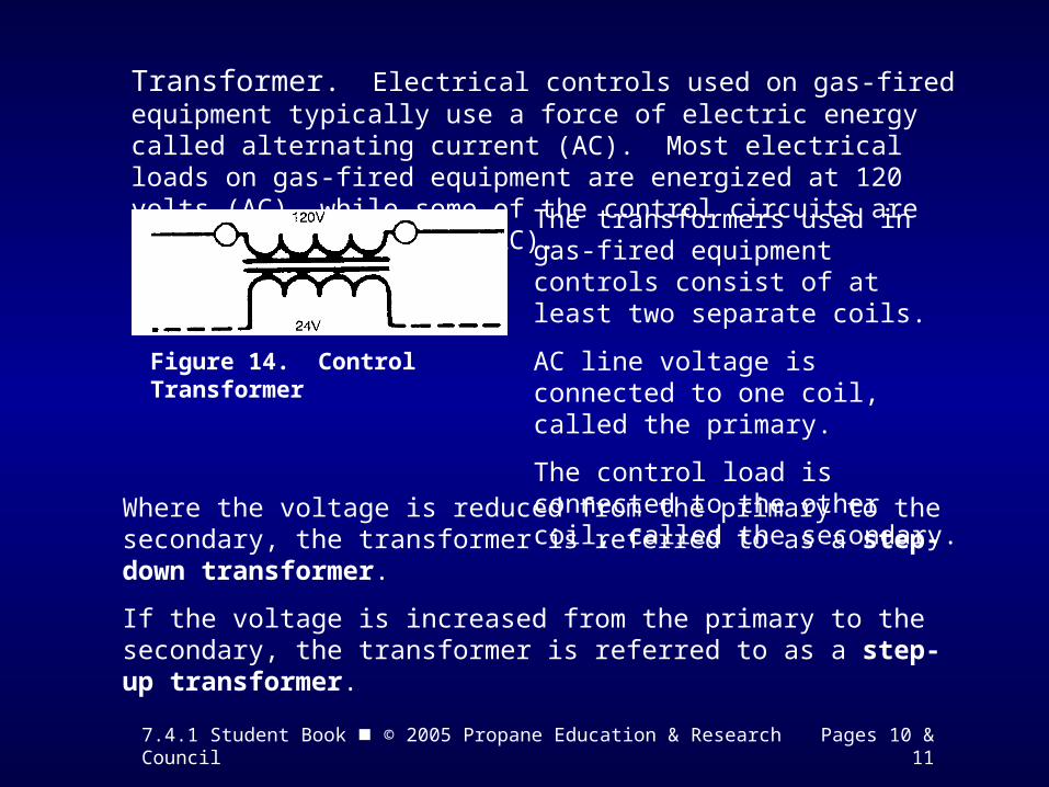
Transformer. Electrical controls used on gas-fired equipment typically use a force of electric energy called alternating current (AC). Most electrical loads on gas-fired equipment are energized at 120 volts (AC), while some of the control circuits are energized at 24 volts (AC).
Figure 14. Control Transformer
The transformers used in gas-fired equipment controls consist of at least two separate coils.
AC line voltage is connected to one coil, called the primary.
The control load is connected to the other coil, called the secondary.
Where the voltage is reduced from the primary to the secondary, the transformer is referred to as a step-down transformer.
If the voltage is increased from the primary to the secondary, the transformer is referred to as a step-up transformer.

7.4.1 Student Book © 2005 Propane Education & Research Council Page 11
Motors
Although there are many types of electric motors, the one most commonly used in gas operated equipment is referred to as a "capacitor start" motor. The blower motor shown is a multiple speed motor.
Figure 15. Blower Motor
The symbol
(or in Figure 15)
represents a disconnect used in the motor circuit.

7.4.1 Student Book © 2005 Propane Education & Research Council Pages 12 & 13
Gas Control Module
There are two different types of electronic ignition systems
• Spark ignition
• Hot surface ignition
Figure 16. Gas Control Module
The flame monitoring circuit in the control module responds only to the direct current produced by flame rectification to prove the presence of the pilot flame.
There are two types of spark ignition systems:
1. Intermittent Pilot Ignition (IID)
2. Direct spark ignition (DSI) has no pilot burner
7.4.1 Student Book © 2005 Propane Education & Research Council Pages 13 & 14
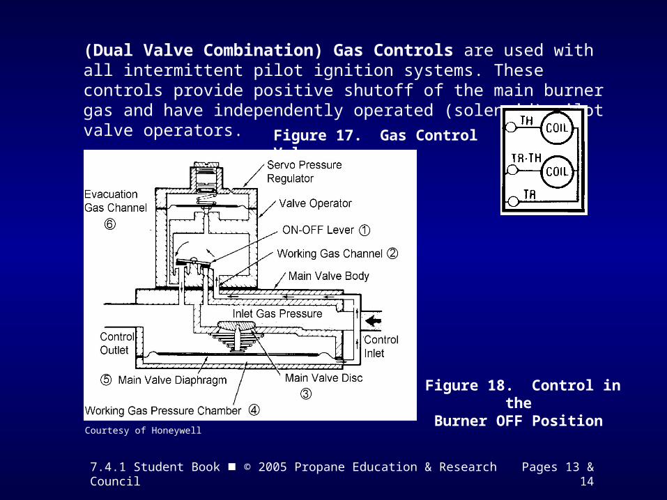
(Dual Valve Combination) Gas Controls are used with all intermittent pilot ignition systems. These controls provide positive shutoff of the main burner gas and have independently operated (solenoid) pilot valve operators.
Figure 17. Gas Control Valve
Figure 18. Control in the Burner OFF Position
Courtesy of Honeywell

7.4.1 Student Book © 2005 Propane Education & Research Council Page 15
Figure 19. Control in the Burner ON Position

7.4.1 Student Book © 2005 Propane Education & Research Council Page 16
Identifying electromagnetic controls
Figure 20. Magnetic Operated Valve
Energizing or de-energizing the solenoid attracts or releases the plunger causing the attached valve seat to open or close the valve. When the coil is energized, the magnetic field around the coil lifts the valve stem and seat, opening the valve and allowing a flow.
Electromagnetic valves are usually called "solenoid valves." Solenoid valves may be used for starting or shutting off the flow of gas.

7.4.1 Student Book © 2005 Propane Education & Research Council Pages 16 & 17
The same electromagnetic principle is used to actuate remote controlled switches. Only a small amount of current is required to pass through the coil to close or open the electrical contacts, which can switch large load currents.
A switch operated by means of a solenoid is called a relay.
Figure 21. Relay: an Electromagnetic Switch

7.4.1 Student Book © 2005 Propane Education & Research Council Page 17
Identifying electromagnetic induction
If a magnetic field is moved past a conductor, or if the conductor is moved through a magnetic field, an electrical force (voltage) is induced in the conductor.
Figure 22. Magnetic Inductionwith a Stationary Coil
As the permanent magnet is moved into or out of the coil, the magnetic lines around the magnet cut across the turns of the coil.
When the turns of the coil are cut by the magnetic lines of force, a voltage is generated across the ends of the coil causing electrical current to flow.

7.4.1 Student Book © 2005 Propane Education & Research Council Pages 17 & 18
One application of the induction effect is the transformer. Figure 23 shows a primary winding (coil) connected to a 120 AC. A secondary winding (coil) is placed close to the primary winding, but is not connected to it.
Figure 23. Transformer Principle

7.4.1 Student Book © 2005 Propane Education & Research Council Page 18
Identifying alternating current (AC)
Alternating current flows in a conductor first in one direction and then in the other direction. These reversals of direction occur periodically and rapidly. Each change of direction is called an alternation and every two alternatives are called a complete cycle.
The number of cycles per second is called the frequency of the alternating current. The standard frequency in the United States is 60 cycles (Hertz) per second.
AC Current Symbol

7.4.1 Student Book © 2005 Propane Education & Research Council Page 18
Identifying transformers
Because of the changing magnetic field caused by alternating current in a conductor, a device called a transformer is used to step-up or step-down the voltage.
Figure 24. Basic “Step-Down” or“Step-Up” Transformer
In the changing magnetic field the voltage in the "primary" and "secondary" will be proportional to the number of turns of wire in the primary and secondary coils.
7.4.1 Student Book © 2005 Propane Education & Research Council Page 19
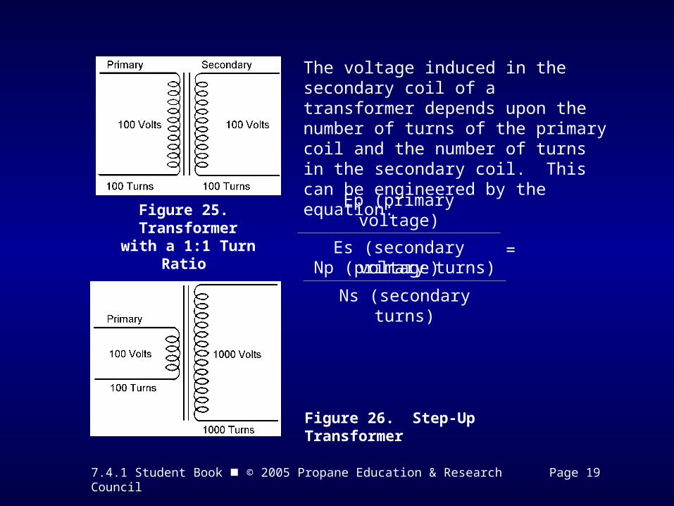
Figure 25. Transformerwith a 1:1 Turn Ratio
The voltage induced in the secondary coil of a transformer depends upon the number of turns of the primary coil and the number of turns in the secondary coil. This can be engineered by the equation:
=Ep (primary voltage)
Es (secondary voltage)
Np (primary turns)
Ns (secondary turns)
Figure 26. Step-Up Transformer
7.4.1 Student Book © 2005 Propane Education & Research Council Page 19
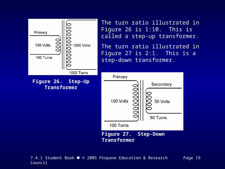
The turn ratio illustrated in Figure 26 is 1:10. This is called a step-up transformer.
The turn ratio illustrated in Figure 27 is 2:1. This is a step-down transformer.
Figure 26. Step-Up Transformer
Figure 27. Step-Down Transformer

7.4.1 Student Book © 2005 Propane Education & Research Council Pages 21 - 25
Time to See If You Got the Key Points of This Module…
• Complete the Review on pages 21 - 24.
• See if you are ready for the Certification Exam by checking off the performance criteria on page 25.